KR101434200B1 - Method and apparatus for identifying sound source from mixed sound - Google Patents
Method and apparatus for identifying sound source from mixed sound Download PDFInfo
- Publication number
- KR101434200B1 KR101434200B1 KR1020070098890A KR20070098890A KR101434200B1 KR 101434200 B1 KR101434200 B1 KR 101434200B1 KR 1020070098890 A KR1020070098890 A KR 1020070098890A KR 20070098890 A KR20070098890 A KR 20070098890A KR 101434200 B1 KR101434200 B1 KR 101434200B1
- Authority
- KR
- South Korea
- Prior art keywords
- sound source
- sound
- signals
- signal
- mixed
- Prior art date
- Legal status (The legal status is an assumption and is not a legal conclusion. Google has not performed a legal analysis and makes no representation as to the accuracy of the status listed.)
- Expired - Fee Related
Links
Images


Classifications
-
- H—ELECTRICITY
- H04—ELECTRIC COMMUNICATION TECHNIQUE
- H04R—LOUDSPEAKERS, MICROPHONES, GRAMOPHONE PICK-UPS OR LIKE ACOUSTIC ELECTROMECHANICAL TRANSDUCERS; DEAF-AID SETS; PUBLIC ADDRESS SYSTEMS
- H04R3/00—Circuits for transducers, loudspeakers or microphones
- H04R3/005—Circuits for transducers, loudspeakers or microphones for combining the signals of two or more microphones
-
- G—PHYSICS
- G10—MUSICAL INSTRUMENTS; ACOUSTICS
- G10L—SPEECH ANALYSIS TECHNIQUES OR SPEECH SYNTHESIS; SPEECH RECOGNITION; SPEECH OR VOICE PROCESSING TECHNIQUES; SPEECH OR AUDIO CODING OR DECODING
- G10L15/00—Speech recognition
- G10L15/08—Speech classification or search
-
- G—PHYSICS
- G10—MUSICAL INSTRUMENTS; ACOUSTICS
- G10L—SPEECH ANALYSIS TECHNIQUES OR SPEECH SYNTHESIS; SPEECH RECOGNITION; SPEECH OR VOICE PROCESSING TECHNIQUES; SPEECH OR AUDIO CODING OR DECODING
- G10L21/00—Speech or voice signal processing techniques to produce another audible or non-audible signal, e.g. visual or tactile, in order to modify its quality or its intelligibility
- G10L21/02—Speech enhancement, e.g. noise reduction or echo cancellation
- G10L21/0272—Voice signal separating
-
- G—PHYSICS
- G10—MUSICAL INSTRUMENTS; ACOUSTICS
- G10L—SPEECH ANALYSIS TECHNIQUES OR SPEECH SYNTHESIS; SPEECH RECOGNITION; SPEECH OR VOICE PROCESSING TECHNIQUES; SPEECH OR AUDIO CODING OR DECODING
- G10L25/00—Speech or voice analysis techniques not restricted to a single one of groups G10L15/00 - G10L21/00
- G10L25/78—Detection of presence or absence of voice signals
-
- H—ELECTRICITY
- H04—ELECTRIC COMMUNICATION TECHNIQUE
- H04R—LOUDSPEAKERS, MICROPHONES, GRAMOPHONE PICK-UPS OR LIKE ACOUSTIC ELECTROMECHANICAL TRANSDUCERS; DEAF-AID SETS; PUBLIC ADDRESS SYSTEMS
- H04R2201/00—Details of transducers, loudspeakers or microphones covered by H04R1/00 but not provided for in any of its subgroups
- H04R2201/40—Details of arrangements for obtaining desired directional characteristic by combining a number of identical transducers covered by H04R1/40 but not provided for in any of its subgroups
- H04R2201/403—Linear arrays of transducers
Landscapes
- Engineering & Computer Science (AREA)
- Acoustics & Sound (AREA)
- Physics & Mathematics (AREA)
- Health & Medical Sciences (AREA)
- Signal Processing (AREA)
- Human Computer Interaction (AREA)
- Audiology, Speech & Language Pathology (AREA)
- Computational Linguistics (AREA)
- Multimedia (AREA)
- General Health & Medical Sciences (AREA)
- Otolaryngology (AREA)
- Quality & Reliability (AREA)
- Circuit For Audible Band Transducer (AREA)
- Obtaining Desirable Characteristics In Audible-Bandwidth Transducers (AREA)
Abstract
본 발명은 혼합 사운드로부터의 음원 판별 방법 및 장치에 관한 것으로, 본 발명에 따른 음원 판별 방법은 마이크로폰 어레이를 통해 입력된 복수 개의 음원들이 포함된 혼합 신호로부터 음원 신호들을 분리하고, 혼합 신호 및 분리된 음원 신호들의 관계로부터 복수 개의 음원들을 혼합하는 혼합 채널의 전달 함수를 추정하고, 분리된 음원 신호들에 추정된 전달 함수를 승산함으로써 마이크로폰 어레이의 입력 신호를 획득하고, 획득된 입력 신호에 기초하여 각각의 음원의 위치 정보를 산출함으로써, 분리된 독립 음원 신호가 어떠한 음원에 해당하는 신호인지를 정확하게 판별하며, 분리된 독립 음원 신호들 중의 특정 음원 신호에 대해 잡음을 제거하거나 음량을 크게 하는 등 마이크로폰 어레이 신호 처리 분야에서 활용되는 다양한 음질 개선 알고리즘을 적용하는 것이 가능하다.The present invention relates to a method and an apparatus for discriminating a sound source from a mixed sound, and a sound source discriminating method according to the present invention separates sound source signals from a mixed signal including a plurality of sound sources inputted through a microphone array, Estimating a transfer function of the mixed channel mixing the plurality of sound sources from the relationship of the sound source signals, obtaining the input signal of the microphone array by multiplying the separated sound source signals by the estimated transfer function, It is possible to accurately determine whether the separated independent sound source signal is a signal corresponding to which sound source, to eliminate noise or to increase the volume of a specific sound source signal of the separated independent sound source signals, Various sound quality improvement in the field of signal processing It is possible to apply the algorithm.
Description
본 발명은 혼합 사운드로부터 음원을 판별하는 방법 및 장치에 관한 발명으로서, 휴대 전화, 캠코더 및 디지털 녹음기 등 음성 신호 처리나 녹음이 가능한 디지털 휴대 기기 등에 입력되는 다양한 음원이 포함된 혼합 사운드로부터 각각의 독립 음원 신호들을 분리하고, 분리된 음원 신호들 중 사용자가 원하는 음원 신호를 가공하는 방법 및 장치에 관한 것이다.The present invention relates to a method and an apparatus for discriminating a sound source from a mixed sound, and more particularly, to a method and apparatus for discriminating a sound source from a mixed sound including a variety of sound sources input to a digital portable device capable of processing and recording a sound signal such as a cellular phone, To a method and apparatus for separating sound source signals and processing a desired sound source signal among separated sound source signals.
휴대용 디지털 기기를 사용하여 전화 통화를 하거나 외부 음성을 녹음하거나 동영상을 취득하는 것이 일상화되는 시대가 도래하였다. 일반적으로 휴대용 디지털 기기를 통해 음원을 녹음하거나 음성 신호를 입력받는 환경은 주변 간섭음이 없이 조용한 환경이기보다는 다양한 소음과 주변 간섭음이 모두 포함되어 있는 환경일 경우가 더 많을 것이다. 이를 위해 혼합 사운드들로부터 각각의 음원을 분리하여 사용자가 필요로 하는 특정 음원만을 추출하거나, 역으로 불필요한 주변 간섭음을 제거하는 기술 등이 제시되었다.The time has come to become commonplace when using portable digital devices to make phone calls, record external voices, or acquire video. Generally, the environment in which a sound source is recorded or a voice signal is inputted through a portable digital device is more likely to be an environment including various noise and peripheral interference rather than a quiet environment without surrounding interference. For this purpose, a technique for extracting only a specific sound source required by the user by separating each sound source from the mixed sounds, and a technique for removing unnecessary peripheral interference sounds are proposed.
종래에는 혼합 사운드들을 분리하여 단순히 사람의 음성과 기타 잡음 정도만 을 판별하는 방법이 이용되어 왔다. 그러나, 비록 종래의 혼합 사운드 분리 방법을 통해서 각각의 음원들을 분리할 수는 있었으나, 분리된 음원들이 어떠한 음원들인지를 정확하게 판별할 수 없었기 때문에 많은 수의 음원들이 포함된 혼합 사운드들로부터 각각의 음원을 정확하게 분리하여 활용하기에는 어려움이 있다.Conventionally, a method has been used in which mixed sounds are simply separated to discriminate only the human voice and other noises. However, although each sound source can be separated through the conventional mixed sound separation method, since it is not possible to accurately determine which sound sources are separated, the sound sources from the mixed sounds including a large number of sound sources It is difficult to accurately separate and utilize them.
본 발명이 해결하고자 하는 기술적 과제는 복수 개의 음원들이 포함된 혼합 사운드로부터 분리된 각각의 음원 신호가 어떠한 음원에 해당하는 신호인지를 정확하게 판별하지 못하는 문제점을 해결하고, 분리된 음원 신호들 각각을 제대로 활용하지 못하고 분리된 음원 신호들로부터 단순히 음성과 기타 잡음을 분리하는 정도에 그치는 기술적 한계를 극복하는 음원 판별 방법 및 장치를 제공하는데 있다.Disclosure of Invention Technical Problem [8] The present invention has been made to solve the above-mentioned problem, and it is an object of the present invention to solve the problem that each sound source signal separated from a mixed sound including a plurality of sound sources can not accurately discriminate a signal corresponding to a sound source, The present invention provides a method and apparatus for discriminating a sound source that overcomes the technical limitations of separating sound and other noises from separated sound source signals without utilizing the sound source.
상기 기술적 과제를 달성하기 위하여, 본 발명에 따른 음원 판별 방법은 마이크로폰 어레이를 통해 입력된 복수 개의 음원들이 포함된 혼합 신호로부터 상기 음원 신호들을 분리하는 단계; 상기 혼합 신호 및 상기 분리된 음원 신호들의 관계로부터 상기 복수 개의 음원들을 혼합하는 혼합 채널의 전달 함수를 추정하는 단계; 상기 분리된 음원 신호들에 상기 추정된 전달 함수를 승산함으로써 상기 마이크로폰 어레이의 입력 신호를 획득하는 단계; 및 상기 획득된 입력 신호에 기초하여 소정의 음원 위치 추정 방법을 통해 상기 각각의 음원의 위치 정보를 산출하는 단계를 포함하는 것을 특징으로 한다.According to an aspect of the present invention, there is provided a method for discriminating a sound source, the method comprising: separating the sound source signals from a mixed signal including a plurality of sound sources input through a microphone array; Estimating a transfer function of a mixed channel that mixes the plurality of sound sources from the mixed signal and the separated relationship of the sound source signals; Obtaining an input signal of the microphone array by multiplying the separated sound source signals by the estimated transfer function; And calculating position information of each sound source through a predetermined sound source position estimation method based on the obtained input signal.
상기 다른 기술적 과제를 해결하기 위하여, 본 발명은 상기 기재된 음원 판별 방법을 컴퓨터에서 실행시키기 위한 프로그램을 기록한 컴퓨터로 읽을 수 있는 기록매체를 제공한다.According to another aspect of the present invention, there is provided a computer-readable recording medium having recorded thereon a program for causing a computer to execute the method for identifying a sound source as described above.
상기 기술적 과제를 달성하기 위하여, 본 발명에 따른 음원 판별 장치는 마 이크로폰 어레이를 통해 입력된 복수 개의 음원들이 포함된 혼합 신호로부터 상기 음원 신호들을 분리하는 음원 분리부; 상기 혼합 신호 및 상기 분리된 음원 신호들의 관계로부터 상기 복수 개의 음원들을 혼합하는 혼합 채널의 전달 함수를 추정하는 전달 함수 추정부; 상기 분리된 음원 신호들에 상기 추정된 전달 함수를 승산함으로써 상기 마이크로폰 어레이의 입력 신호를 추정하는 입력 신호 획득부; 및 상기 추정된 입력 신호에 기초하여 소정의 음원 위치 추정 방법을 통해 상기 각각의 음원의 위치 정보를 산출하는 위치 정보 산출부를 포함하는 것을 특징으로 한다.According to an aspect of the present invention, there is provided a sound source discrimination apparatus comprising: a sound source separation unit for separating sound source signals from a mixed signal including a plurality of sound sources inputted through a microphone array; A transfer function estimating unit that estimates a transfer function of a mixed channel that mixes the plurality of sound sources from the mixed signal and the separated relationship of the sound source signals; An input signal obtaining unit for estimating an input signal of the microphone array by multiplying the separated sound source signals by the estimated transfer function; And a position information calculation unit for calculating position information of each sound source through a predetermined sound source position estimation method based on the estimated input signal.
본 발명은 복수 개의 음원들이 포함된 혼합 사운드로부터 분리된 각각의 음원에 대해 마이크로폰 어레이의 입력 신호를 획득함으로써 분리된 음원 신호가 어떠한 음원에 해당하는 신호인지를 정확하게 판별하고, 획득된 입력 신호에 기초하여 각각의 음원에 대한 위치 정보를 산출함으로써 특정 음원 신호에 대해 잡음을 제거하거나 음량을 크게 하는 등 마이크로폰 어레이 신호 처리 분야에서 활용되는 다양한 음질 개선 알고리즘을 적용하는 것이 가능하다.According to the present invention, by obtaining an input signal of a microphone array for each sound source separated from a mixed sound including a plurality of sound sources, it is possible to accurately determine which sound source signal corresponds to which sound source, It is possible to apply various sound quality improvement algorithms used in the field of microphone array signal processing, such as eliminating noise or increasing the volume of a specific sound source signal by calculating position information on each sound source.
이하에서는 도면을 참조하여 본 발명의 다양한 실시예들을 상세히 설명한다.Hereinafter, various embodiments of the present invention will be described in detail with reference to the drawings.
도 1은 본 발명이 해결하려는 문제의 상황과 이를 해결하는 장치를 개념적으로 도시한 도면으로서, 마이크로폰 어레이(microphone array)(101)로부터 각각 다른 거리만큼 떨어져 위치한 4 개의 음원들(S1, S2, S3 및 S4)로부터 음원들을 취득하는 상황을 가정한 것이다. 이러한 4 개의 음원들은 마이크로폰 어레이(101)로부 터의 거리뿐만 아니라 마이크로폰 어레이에 대해 위치한 각도, 음원의 종류, 음원의 성질 및 음원의 크기 등 음원의 특징을 구성할 수 있는 다양한 요소들이 서로 다른 환경을 가정하고 있다. 이러한, 혼합 사운드 환경이 일상 생활에서 사용자가 대하는 통상의 환경이 될 수 있을 것이기 때문이다.FIG. 1 conceptually illustrates a situation of a problem to be solved by the present invention and an apparatus for solving the same, wherein four sound sources S1, S2, S3 (each of which is located at a different distance from the microphone array 101) And S4). These four sound sources are different from each other in terms of the distance from the
상기 가정 하에서 음원을 취득하려는 장치는 크게 마이크로폰 어레이(101), 음원 분리부(102) 및 음원 처리부(103)로 구성된다. 마이크로폰 어레이(101)는 4 개의 음원들을 입력받는 입력부로서, 통상의 단일 마이크로폰으로도 구현이 가능할 것이나, 각기 다른 4 개의 음원들로부터 좀 더 많은 정보들을 수집하고, 수집된 음원 신호를 용이하게 가공하기 위해서는 복수 개의 마이크로폰으로 구성되는 마이크로폰 어레이인 것이 좀 더 유리할 것이다. 음원 분리부(102)는 마이크로폰 어레이를 통해 입력된 혼합 사운드를 분리하는 역할을 수행하는 장치로, 도 1의 실시예에서는 혼합 사운드로부터 4 개의 음원들(S1, S2, S3 및 S4)이 분리되어 나올 것이다. 이러한 분리된 음원들을 음원 처리부(103)를 통해 음질을 향상시키거나, 음량(gain)을 크게 하는 등의 처리를 한다.An apparatus for acquiring a sound source under the above assumption mainly includes a
이상과 같이 다수의 음원 신호들이 혼합된 혼합 신호로부터 원래의 음원 신호들을 분리해내는 문제를 암묵 신호 분리(blind source separation, 이하 BSS라 한다.)이라고 한다. 즉, BSS는 신호 소스에 대한 아무런 사전 정보 없이 혼합 신호로부터 각각의 소스를 분리해내는 것을 목적으로 한다. 이러한 BSS를 해결하는 수단 내지 기술 중 하나가 독립 요소 해석(independent component analysis, 이하 ICA라 한다.) 기법으로서 도 1에서의 음원 분리부(102)가 수행하는 역할이 바로 ICA이다. ICA는 복수 개의 신호가 서로 섞여서 마이크로폰(microphone)을 통해 수집되고, 수집된 신호들로부터 원래의 신호들이 서로 통계적으로 독립이라는 조건만을 이용하여 혼합되기 전의 신호들 및 혼합 행렬을 찾아내는 방법이다. 여기서 통계적으로 독립이라는 것은 혼합 신호를 구성하는 개별 신호들이 서로 간에 해당 신호에 대한 어떠한 정보도 제공하지 않는다는 것을 의미한다. 즉, ICA에 의한 음원 분리 기술은 통계적으로 서로 독립인 음원 신호 자체만을 출력할 수 있으며, 분리된 음원 신호들이 최초에 어떠한 음원 신호들이었는지에 대해서는 정보를 제공하지 않는다. The problem of separating the original sound source signals from the mixed signal in which a plurality of sound source signals are mixed is referred to as blind source separation (BSS). That is, the BSS aims to separate each source from the mixed signal without any prior knowledge of the signal source. One of the means and techniques for solving such a BSS is the ICA, which is performed by the sound
따라서, 음원 분리부(102)를 통해 분리된 음원들을 보다 정교하게 가공하고 활용하기 위해서는 음원 처리부(103)를 통해 추가적으로 음원의 방향 및 거리 등과 같은 음원 정보를 추출하는 과정이 필요하다. 이러한 음원 처리 과정은 마이크로폰 어레이 입력 신호, 즉 분리된 음원들이 최초에 마이크로폰 어레이에 입력될 때 어떠한 신호들이었는지를 판별하는 것을 의미한다. 이하에서는 이상의 문제 상황 및 이를 해결하기 위한 음원 처리부(103)를 중심으로 본 발명의 구성에 대한 개념(concept)을 보다 구체적으로 제시한다.Accordingly, in order to more finely process and utilize the sound sources separated through the sound
도 2는 본 발명의 일 실시예에 따른 혼합 사운드로부터의 음원 판별 장치를 도시한 블럭도로서, 크게 마이크로폰 어레이(100), 음원 분리부(200), 입력 신호 획득부(300), 위치 정보 산출부(400) 및 음질 향상부(500)로 구성된다.FIG. 2 is a block diagram illustrating a sound source discrimination apparatus according to an embodiment of the present invention. The
음원 분리부(200)는 다양한 ICA 알고리즘들을 이용하여 마이크로폰 어레이(100)를 통해 입력받은 혼합 사운드로부터 각각의 독립 음원을 분리한다. 이 러한 ICA 알고리즘들에는 대표적으로 infomax, FastICA 및 JADE 등이 널리 알려져 있으며, 본 발명이 속하는 기술 분야에서 통상의 지식을 가진 자가 용이하게 파악할 수 있는 것이다. 음원 분리부(200)를 통해 혼합 사운드는 통계적으로 다른 속성을 갖는 독립 음원들로 분리되지만, 각각의 독립 음원이 혼합 사운드로 마이크로폰 어레이(100)에 입력되기 전에 어느 방향에 위치해 있는지, 얼마만큼 떨어져 있는지, 잡음인지 아닌지 등의 보다 구체적인 정보에 대해서는 알 수 없다. 따라서, 분리된 독립 음원에 대한 방향 및 거리 등의 부가 정보들을 정밀하게 추정하기 위해서는 종래와 같이 단순히 음성과 잡음만을 판별하는 정도가 아니라 각 음원에 대한 마이크로폰 어레이의 입력 신호를 획득하는 것이 필요하다.The sound
입력 신호 획득부(300)는 음원 분리부(200)를 통해 분리된 음원에 대하여 마이크로폰 어레이의 입력 신호를 획득한다. 이를 위해 전달 함수 추정부(350)는 복수 개의 음원들이 혼합 신호로서 마이크로폰 어레이(100)에 입력될 때의 혼합 채널(mixing channel)에 대한 전달 함수(transfer function)를 추정한다. 여기서 혼합 채널의 전달 함수란, 복수 개의 음원들을 혼합 신호로 혼합하는 입력과 출력의 비를 의미하는 것으로, 좁은 의미에서는 복수 개의 음원 신호들과 혼합 신호를 푸리에 변환(Fourier transform) 함수로 바꿈으로써 변환된 신호들의 비를 의미하고, 넓은 의미에서는 입력 신호로부터 출력 신호에의 신호의 전달 특성을 나타내는 함수를 의미한다. 혼합 채널의 전달 함수를 추정하는 과정을 보다 상세하게 설명하면 다음과 같다.The input
우선, 음원 분리부(200)에서는 ICA의 학습 규칙(learning rule)을 이용한 통 계적인 음원 분리 과정을 통해 상기 혼합 신호 및 상기 분리된 음원 신호들의 관계에 관한 분리 채널(unmixing channel)을 결정한다. 결정된 분리 채널은 전달 함수 추정부(350)에서 추정하고자 하는 전달 함수와 역(inverse)의 상관 관계를 갖는다. 따라서, 전달 함수 추정부(350)는 결정된 분리 채널의 역을 구함으로써 전달 함수를 추정할 수 있다. 이어서, 입력 신호 획득부(300)는 분리된 음원 신호들에 추정된 전달 함수를 승산(multiplication)함으로써 마이크로폰 어레이의 입력 신호를 획득한다.First, the sound
위치 정보 산출부(400)는 입력 신호 획득부(300)에 의해 획득된 마이크로폰 어레이의 입력 신호에 대해 각각의 음원들별로 주변 간섭음이 없는 상태에서 음원들의 위치 정보를 정밀하게 추정한다. 주변 간섭음이 없는 상태라 함은 음원들 상호간에 간섭이 없이 각각의 음원들 하나만이 존재하는 환경을 의미한다. 즉, 입력 신호 획득부(300)에 의해 획득된 신호들은 각각 하나의 음원만을 포함하게 된다. 이러한 입력 신호들에 대한 위치 정보를 추정하기 위해 위치 정보 산출부(400)는 이상에서 추정된 입력 신호에 기초하여 도착 시간 지연법(TDOA, time delay of arrival), 빔 형성 방법(beam-forming), 고해상도 스펙트럼 추정 방법(spectral analysis) 등의 다양한 음원 위치 추정 방법들을 통해 상기 각각의 음원의 위치 정보를 산출한다. 이러한 다양한 위치 추정 방법들은 본 발명이 속하는 기술 분야에서 통상의 지식을 가진 자가 용이하게 파악할 수 있는 것으로, 위치 정보 추정 방법을 간단히 설명하면 다음과 같다.The position
우선, 도착 시간 지연법에 따르면 위치 정보 산출부(400)는 음원으로부터 마 이크로폰 어레이(100)로 입력되는 신호에 대하여 어레이를 구성하는 마이크로폰들을 2 개씩 짝(pair)을 지어 마이크로폰들 간의 시간 지연을 측정하고, 측정된 시간 지연으로부터 음원의 방향을 추정한다. 이어서, 위치 정보 산출부(400)는 각각의 짝에서 추정된 음원 방향들이 교차하는 공간상의 지점에 음원이 존재한다고 추정하게 된다. 또 다른 방법으로 제시된 빔 형성 방법에 따르면 위치 정보 산출부(400)는 특정 각도의 음원 신호에 지연을 주고 각도에 따라 공간 상의 신호들을 스캔(scan)하여 스캔된 신호값이 가장 큰 위치를 선택함으로써 음원의 위치를 추정하게 된다.First of all, according to the arrival time delay method, the position
이상과 같이 하나의 음원 신호만이 존재하는 경우의 음원에 대한 방향 및 거리 등의 위치 정보를 산출함으로써 혼합 사운드로부터 위치 정보를 산출하는 방식에 비해 보다 정확하고 용이한 신호 처리가 가능하다. 더불어 본 발명에서는 위치 정보 산출부(400)를 통해 산출된 위치 정보에 기초하여 특정 음원을 가공하는 방법 및 장치를 제안한다. 이를 위한 일 실시예로서 도 2에서 음질 향상부(500)는 이상에서 산출된 위치 정보를 이용하여 상기 음원들 중 소정 음원의 신호 대 잡음비(SNR, signal to noise ratio)를 개선함으로써 음질을 향상시킨다. 신호 대 잡음비란 대상 신호에 잡음이 얼마나 포함되어 있는지를 비율로 표현한 값이다.As described above, it is possible to perform more accurate and easier signal processing than the method of calculating the position information from the mixed sound by calculating the position information such as the direction and the distance to the sound source in the case where only one sound source signal exists. In addition, the present invention proposes a method and apparatus for processing a specific sound source on the basis of position information calculated through the position
위치 정보 산출부(400)를 통해 음원에 대한 거리 및 방향을 비롯한 다양한 위치 정보가 산출되었으므로, 음질 향상부(500)에서는 각 음원 신호들을 거리 및 방향에 따라 정렬함으로써 사용자가 원하는 거리나 방향에 위치한 음원에 대한 특정 음원 신호들을 선택할 수 있다. 또한, 이렇게 선택된 특정 음원에 대해 빔 형성(beam-forming)과 같은 공간 필터(spatial filter)를 이용하여 분리된 독립 음원의 신호 대 잡음비를 개선함으로써 음질을 향상시키거나 음량을 증폭시키는 등 다양한 가공 방법을 적용할 수 있다. 예를 들어, 분리된 독립 음원에 포함되는 특정의 공간 주파수 성분을 필터를 통해 강조하거나 감쇠할 수 있다. 신호 대 잡음비를 개선하기 위해서는 사용자가 얻고자 하는 대상 신호를 강조해야 할 것이며, 잡음으로 간주하여 제거하고자 하는 신호는 필터를 통해 감쇠시켜야 할 것이다.Since various position information including the distance and direction to the sound source is calculated through the position
일반적으로 2 개 이상의 마이크로폰들로 이루어진 마이크로폰 어레이는 배경 잡음과 섞인 목표 신호를 고감도로 수신하기 위해 마이크로폰 어레이에 수신된 각각의 신호에 적절한 가중치를 주어 진폭을 향상시킴으로써 원하는 목표 신호와 잡음 신호의 방향이 다를 경우의 잡음을 공간적으로 줄일 수 있는 필터 역할을 수행하게 되는데, 이러한 일종의 공간적 필터를 빔 형성이라고 한다. 따라서, 이러한 빔 형성을 이용한 음질 향상부(500)를 통해 사용자는 분리된 독립 음원들 중 사용자가 원하는 특정 음원의 음질을 개선할 수 있으며, 본 발명이 속하는 기술 분야에서 통상의 지식을 가진 자는 이러한 음질 향상부(500)가 선택적으로 적용될 수 있으며, 또한 음질 향상부(500)를 대신하여 다양한 빔 형성 알고리즘을 통한 음원 신호 가공 방법이 추가적으로 적용될 수 있음을 알 수 있다. In general, a microphone array composed of two or more microphones can improve the amplitude by giving a proper weight to each signal received in the microphone array in order to receive a target signal mixed with background noise with a high sensitivity, so that a desired target signal and a direction of a noise signal The spatial filter is a type of filter that can reduce noise in a different way. Accordingly, the user can improve the sound quality of a specific sound source desired by the user through the sound
도 3은 도 2에 도시한 본 발명의 일 실시예에 따른 음원 판별 장치에서 각각의 구성을 좀 더 구체적으로 도시한 블럭도로서, 도 2와 유사하게 4 개의 마이크로폰으로 구성된 마이크로폰 어레이(100), 음원 분리부(200), 입력 신호 획득부(300), 위치 정보 산출부(400) 및 음질 향상부(500)로 구성되며, 혼합 사운 드는 S1, S2, S3 및 S4의 4 개의 음원으로 구성된다고 가정하자.FIG. 3 is a block diagram showing a more detailed configuration of each of the sound source discrimination apparatuses according to the embodiment of the present invention shown in FIG. 2. In FIG. 3, a
마이크로폰 어레이(100)는 4 개의 독립 음원들이 4 개의 마이크로폰으로 입력되는 비율에 따라 결합된 형태인 혼합 사운드로서 입력받는다. S1, S2, S3 및 S4의 4 개의 음원들을 S라고 하고, 마이크로폰 어레이(100)에 입력되는 혼합 신호를 X라고 할 때, 양자의 관계는 다음의 수학식 1과 같이 표현된다.The
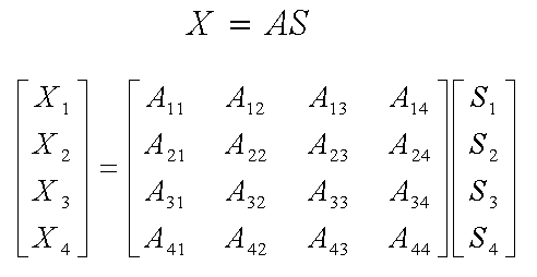
여기서 A 또는 Aij는 음원 신호들을 혼합하는 혼합 채널(mixing channel) 또는 혼합 행렬(mixing matrix)로서, i는 센서(각각의 microphone을 의미한다.)의 인덱스(index)를, j는 음원(source)의 인덱스를 의미한다. 즉, 수학식 1은 4 개의 음원으로부터 혼합 채널을 통해 마이크로폰 어레이를 구성하는 4 개의 마이크로폰에 입력되는 혼합 신호를 표현한 것이다.Where A or A ij is a mixing channel or mixing matrix for mixing the source signals, i is the index of the sensor (meaning microphone), j is the source ) ≪ / RTI > That is, Equation (1) represents a mixed signal input from four sound sources to four microphones constituting a microphone array through a mixed channel.
최초에 혼합 신호를 형성하는 각각의 음원 신호들은 미지의(unknown) 값이기 때문에 혼합 신호를 입력받는 환경과 목표로 하는 대상을 고려하여 미리 입력 신호의 수를 설정하여야 할 것이다. 본 실시예에서는 이러한 입력 신호의 수를 4 개로 설정하였으나, 현실적으로 외부의 음원 신호가 4 개에 지나지 않는 경우는 드물 것 이다. 만약, 미리 설정한 수보다 외부의 음원 신호가 더 많을 경우 분리되어 나온 4 개의 독립 음원 중 일부에는 하나 이상의 음원이 포함되어 있을 수도 있다. 따라서, 목표 신호의 크기와 환경을 고려하여 매우 작은 음압을 갖는 잡음이나 기타 불필요한 잡음이 독립 음원으로서 분리되어 나오지 않도록 적절한 수의 음원의 인덱스 j를 설정할 필요가 있다.Since each of the sound source signals forming the mixed signal is an unknown value, it is necessary to set the number of input signals in advance in consideration of the environment in which the mixed signal is input and the target object. Although the number of such input signals is set to four in the present embodiment, it is rare that the number of external sound source signals is less than four. If there are more external sound source signals than the preset number, one or more sound sources may be included in some of the four independent sound sources separated from each other. Therefore, it is necessary to set an index j of an appropriate number of sound sources so that noise or other unnecessary noise having a very small sound pressure is not separated as an independent sound source in consideration of the size and environment of the target signal.
음원 분리부(200)는 ICA의 분리 알고리즘을 이용하여 통계적으로 서로 독립인 4 개의 음원들(S1, S2, S3 및 S4)이 포함된 혼합 사운드 X로부터 각각의 독립 음원 Y를 분리한다. 도 1에서 설명한 바와 같이 음원에 대한 정보 없이 혼합 신호로부터 각각의 음원을 분리해야 하는 BSS에서는 마이크로폰 어레이를 통해 입력된 혼합 사운드 X만을 알고 있을 때, 최초의 음원 S와 혼합 채널 A를 추정하는 것을 목적으로 한다. 따라서, 독립 음원들을 분리시키기 위해서 음원 분리부(200)는 혼합 사운드 X의 각 구성 요소들이 서로 통계적으로 독립적이 되도록 하는 분리 채널 W를 찾는다. 그리고, 이를 위해 ICA는 음원 분리부(200)로 하여금 원래의 음원 신호들이 혼합 사운드로서 입력되는 혼합 채널을 분리시킬 수 있는 분리 채널(unmixing channel)을 학습(learning)시킨다. 즉, 음원 분리부(200)는 미지의(unknown) 분리 채널을 학습함으로써 분리된 독립 음원 Y를 근사적으로 최초의 음원 S와 유사한 값이 되도록 갱신한다. ICA 기술을 이용하여 미지의 채널을 학습하는 방법은 본 발명이 속하는 기술 분야에서 통상의 지식을 가진 자에게 널리 알려져 있는 것이다. (T. W. Lee, Independent component analysis - theory and applications, Kluwer, 1998)The sound
이상의 혼합 사운드 X와 분리된 독립 음원 Y의 관계는 다음의 수학식 2와 같이 표현된다.The above-described relationship between the mixed sound X and the separated independent sound source Y is expressed by the following equation (2).

여기서, W는 분리 채널(unmixing channel) 또는 분리 행렬(unmixing matrix)로서, 미지의 값이다. 수학식 2는 마이크로폰 어레이(100)를 통해 입력값으로 측정된 혼합 사운드 X의 각 구성 요소인 X1, X2, X3 및 X4로부터 ICA의 학습 규칙(learning rule)을 이용하여 분리 채널 W를 얻을 수 있음을 의미한다.Here, W is an unmixing channel or an unmixing matrix, which is an unknown value. Equation (2) can obtain the separation channel W using the learning rule of ICA from X1, X2, X3, and X4, which are components of the mixed sound X measured as input values through the
입력 신호 획득부(300)는 분리된 독립 음원 Y에 대한 전달 함수를 추정함으로써 마이크로폰 어레이의 입력 신호를 획득하는 것으로서, 전달 함수 추정부(미도시)를 포함한다. 전달 함수 추정부(미도시)는 음원 분리부(200)로부터 분리된 독립 음원 Y에 대하여 독립 음원을 분리하는 분리 채널의 역(inverse)을 구함으로써 전달 함수를 추정한다. 왜냐하면 전달 함수가 혼합 채널 A를 대상으로 하고 있기 때문에, 혼합 채널 A와 상반되는 분리 채널 W가 결정되면 분리 채널 W의 역을 구함으로써 혼합 채널 A에 대한 전달 함수를 추정할 수 있기 때문이다. 이어서, 입력 신호 획득부(300)는 추정된 전달 함수를 분리된 독립 음원 Y에 승산(multiplication) 함으로써 각각의 독립 음원(S1, S2, S3 및 S4)이 마이크로폰 어레이(100)에 입력될 때의 입력 신호에 해당하는 신호(Z1, Z2, Z3 및 Z4)를 생성한다.The input
이상에서 생성된 신호(Z1, Z2, Z3 및 Z4)는 마이크로폰 어레이(100)에 최초로 입력된 혼합 사운드 X와는 달리 하나의 음원에 대해 마이크로폰 어레이(100)에 입력된 입력 신호라는 점에서 차이가 있다. 예를 들어, 도 3에서 마이크로폰 어레이(100)에 입력된 혼합 사운드 X가 S1, S2, S3 및 S4의 모든 음원 신호를 포함하고 있는데 반해, 입력 신호 획득부(300)를 통해 획득된 Z1은 S1에 대한 음원 신호만을 포함하고 있다는 차이가 있다. 따라서, 입력 신호 획득부(300)를 통해 획득된 마이크로폰 어레이의 입력 신호 S1, S2, S3 및 S4는 신호들 각각이 서로 영향을 주지 않고 마치 하나의 신호만이 존재하는 환경 하에서 해당 신호를 측정하는 것과 같은 효과나 나타나며, 그 결과 음원의 방향, 거리 등 각각의 음원 신호들에 관한 위치 정보들을 정확하게 추출하여 활용하는 것이 가능하다.The signals Z1, Z2, Z3, and Z4 generated above are different from the mixed sound X initially input to the
이상의 과정을 통해 음원 분리부(200)로부터 분리된 독립 음원 Y와 입력 신호 획득부(300)를 통해 추정된 입력 신호 Z(Z1, Z2, Z3 및 Z4)의 관계는 다음의 수학식 3과 같이 표현된다.The relationship between the independent sound source Y separated from the sound

여기서, W- 1는 음원 분리부(200)의 분리 행렬(unmixing matrix)에 대한 역행 렬로서, 입력 신호 획득부(300)의 전달 함수 추정부(미도시)에 의해 전달 함수 A를 추정한다. 따라서, 수학식 3은 혼합 채널 A와 분리 채널 W가 역의 관계에 있다는 것을 의미하며, 음원 분리부(200)을 통해 분리된 독립 음원 Y에 전달 함수 추정부(미도시)에 의해 추정된 혼합 채널 A의 전달 함수를 승산함으로써 마이크로폰 어레이의 입력 신호 Z를 추정할 수 있음을 의미한다.Here, W - 1 is an inverse matrix for an unmixing matrix of the sound
상기 수학식 3에 의해 각각의 음원 S1, S2, S3 및 S4에 대한 마이크로폰 어레이의 입력 신호의 구성 요소를 구체적으로 표시하면 다음의 수학식 4와 같다.The components of the input signal of the microphone array for each of the sound sources S1, S2, S3, and S4 may be specifically expressed by Equation (3) below.
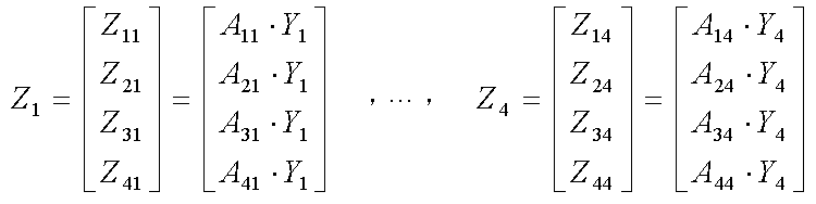
수학식 4에서 혼합 채널 A(전달 함수의 대상을 의미한다.)의 성분은 수학식 1에 표시된 혼합 행렬 A의 열(column) 성분과 같다. 예를 들어, Z1의 경우 혼합 채널 A의 성분은 A11, A21, A31 및 A41과 같이 수학식 1의 혼합 행렬 A의 첫 번째 열 성분이다. 이는 최초에 입력된 혼합 음원과는 달리 각각 하나의 음원 성분에 대해서만 행렬 곱 연산이 수행되므로 Z1의 경우에는 첫 번째 열 성분인 A11, A21, A31 및 A41만 남게 된다. 마찬가지로, Z4의 경우에는 네 번째 열 성분인 A14, A24, A34 및 A44만 남게 된다. 이상에서 수학식 3과 수학식 4를 참조하면 입력 신호 획득부(300)를 통 해 각각의 음원(S1, S2, S3 및 S4)에 대한 마이크로폰 어레이의 입력 신호를 획득할 수 있음을 알 수 있다.In Equation (4), the component of the mixed channel A (which means the object of the transfer function) is the same as the column component of the mixing matrix A shown in Equation (1). For example, in the case of Z 1 , the components of the mixed channel A are the first column components of the mixing matrix A of
위치 정보 산출부(400) 및 음질 향상부(500)는 이상의 도 2에서 설명한 바와 동일하므로 자세한 설명은 생략한다.The location
한편, 일반적으로 ICA에 의한 음원 분리 과정에서는 컨벌루션(convolution) 혼합 채널의 신호를 좀 더 쉽게 다루기 위해 주파수 영역(frequency domain)에서의 분리 방법을 사용한다. 주파수 밴드별로 ICA를 수행하면 독립된 음원 신호들이 추출되는데, 정렬된 순서가 주파수 밴드마다 차이가 나므로 IFFT(inverse fast Fourier transform; 역 고속 푸리에 변환)를 통해 시간 영역(time domain) 신호로 변환할 경우 정렬 순서가 뒤바뀌는 문제가 발생한다. 결과적으로 순서가 뒤바뀐 신호들로 인해 독립 음원 신호들이 제대로 추출되지 못하게 된다. 또한, 전달 함수와 독립 음원 신호들의 곱으로 표현된 하나의 수식에서 그 결과만을 알 수 있고, 전달 함수와 독립 음원 신호들은 미지의 값이기 때문에 각각의 값을 결정할 수 없는 모호성 문제가 발생한다. 예를 들어, 미지수가 3 개인 식에서 알려진 값이 1개 뿐이면 나머지 2 개의 미지수를 결정할 수 없고, 상기 2 개의 미지수에 대한 해(solution)로서 다양한 조합이 후보로 추정될 수 있을 것이다. 이러한 문제를 치환 및 스케일링 모호성(permutation and scaling ambiguity)이라고 하며, 이하의 도 4a 내지 도 4b를 통해 자세히 설명한다.On the other hand, in the process of separating a sound source by ICA, a frequency domain separation method is used to more easily handle a signal of a convolution mixed channel. When ICA is performed for each frequency band, independent sound source signals are extracted. Since the sorted order differs from one frequency band to another, the inverse fast Fourier transform (IFFT) There is a problem that the order is reversed. As a result, the discrete signals are not properly extracted due to the reversed signals. In addition, only the result can be known from a single expression expressed by a product of a transfer function and independent sound signals, and ambiguity problems arise in which transfer functions and independent sound signals can not be determined because they are unknown values. For example, if there is only one known value in an equation with three unknowns, the remaining two unknowns can not be determined, and various combinations as a solution to the two unknowns can be estimated as candidates. This problem is referred to as permutation and scaling ambiguity, and will be described in detail with reference to FIGS. 4A to 4B.
도 4a는 본 발명의 일 실시예에 따른 음원 판별 장치에서 혼합 사운드로부터 독립 음원을 분리할 때 발생하는 치환 모호성(permutation ambiguity)을 도시한 도 면이다.4A is a diagram illustrating a permutation ambiguity generated when an independent sound source is separated from a mixed sound in a sound source discriminating apparatus according to an embodiment of the present invention.
FFT(fast Fourier transform; 고속 푸리에 변환)(401)은 신호 처리의 편의를 위해 시간 영역의 혼합 신호를 주파수 영역으로 변환한다. 이어서, ICA(402)는 각각의 주파수 밴드별로 변환된 혼합 신호에 대해 독립 음원 신호들을 분리한다. 이 과정에서 상기 치환 모호성 문제가 발생한다. 도 4a에서 ICA(402)를 통해 분리된 독립 음원들의 구성 요소의 순서를 살펴보면, 치환 모호성 해결부(403)의 윗 쪽에 도시된 독립 음원 Y4-Y1-Y2-Y3와 아랫 쪽에 도시된 독립 음원 Y3-Y4-Y2-Y1의 순서가 서로 다른 것을 알 수 있다. 즉, 추출된 독립 음원들을 주파수 밴드별로 순서대로 결합하게 되면 정렬된 순서가 서로 달라 정확한 독립 음원 신호를 얻을 수 없다. 이를 해결하기 위해, 도 4a의 치환 모호성 해결부(403)는 입력값인 독립 음원 Y4-Y1-Y2-Y3와 독립 음원 Y3-Y4-Y2-Y1의 정렬 순서를 바로잡아 양자 모두 Y4-Y3-Y2-Y1의 출력값을 생성한다. IFFT(404)는 주파수 영역의 독립 음원들을 다시 시간 영역 신호로 변환함으로써 최종적으로 독립 신호들을 생성한다.A fast Fourier transform (FFT) 401 converts a time-domain mixed signal into a frequency domain for convenience of signal processing. Then, the
치환 및 스케일링 모호성을 수학식 3과 도 3을 참조하여 설명하면 다음과 같다. 도 3에서 입력 신호 획득부(300)를 통해 W-1에 근사한 혼합 채널 A의 전달 함수가 추정되어야 하는데, A와 일치하는 값이 아닌 다소 다른 값이 추정되는 현상이 발생한다. A가 아닌 다른 값을 H라고 표시하여 수학식 3을 다시 정리하면 다음의 수학식 5와 같다.Substitution and scaling ambiguity will be described with reference to equations (3) and (3). In FIG. 3, the transfer function of the mixed channel A approximated to W -1 must be estimated through the input
![]()
![]()
여기서, P는 치환(permutation) 행렬을 의미하고, D는 대각(diagonal) 행렬을 의미한다. 상기 수학식 3과 비교할 때, 의도하지 않았던 P와 D가 추가되었으며, 이로 인해 정확한 독립 음원이 추출되지 못하게 된다. 보다 상세하게 수학식 5의 의미를 살펴보면, 우선 치환 행렬 P를 예시하면 다음의 수학식 6과 같다.Here, P denotes a permutation matrix, and D denotes a diagonal matrix. Compared with Equation (3), unintended P and D are added, which makes it impossible to extract an accurate independent sound source. In more detail, referring to the meaning of Equation (5), the substitution matrix P is expressed as Equation (6) below.

치환 행렬 P는 하나의 행(row)에서 하나의 구성 요소만을 선택하게 하는 행렬이다. 예를 들어, 치환 행렬 P에 4 개의 구성 요소를 갖는 입력값을 행렬 곱할 경우, 행렬 곱의 결과는 각각의 구성 요소가 하나씩 추출되지만, 그 순서는 최초의 입력값과 달리 뒤바뀌게 될 것이다. 즉, 치환 행렬은 입력되는 음원들의 순서를 임의로 치환하는 역할을 한다. 따라서, 수학식 5에서 치환 행렬 P를 승산한다는 것은 상기 도 4a에서 설명한 바와 같이 주파수 밴드마다 정렬 순서가 뒤바뀌는 현상이 나타나는 것을 의미한다.The permutation matrix P is a matrix that allows only one component to be selected in one row. For example, matrix multiplication of input values with four components in a permutation matrix P results in matrix multiplication, where each component is extracted one by one, but the order will be reversed unlike the original input value. That is, the permutation matrix arbitrarily substitutes the order of input sound sources. Therefore, multiplying the permutation matrix P in Equation (5) means that the sorting order is reversed for every frequency band as described with reference to FIG. 4A.
이러한 치환 모호성을 해결하기 위한 방법으로 추정된 ICA의 분리 행렬로부터 지향성 패턴(directivity pattern)을 추출하고, 널링 포인트(nulling point)에 따라 분리 행렬의 행 벡터(row vector)를 정렬함으로써 독립 음원의 구성 요소들의 어긋난 순서를 바로잡는 방법이 널리 이용되고 있다. (Hiroshi Sawada, et. al, "A robust and precise method for solving the permutation problems of frequency-domain blind source separation", IEEE Trans. Speech and Audio Processing, Vol. 12, No. 5, pp.530-538, Sep. 2004)In order to solve this ambiguity of substitution, the directivity pattern is extracted from the ICA separation matrix, and the row vector of the separation matrix is aligned according to a nulling point, A method of correcting the order of offset of elements is widely used. (Hiroshi Sawada, et al., "A robust and precise method for solving the permutation problems of frequency-domain blind source separation", IEEE Trans. Speech and Audio Processing, Vol. 12, No. 5, pp. Sep. 2004)
다음으로, 대각 행렬 D를 예시하면 다음의 수학식 6과 같다.Next, the diagonal matrix D is expressed by Equation (6).
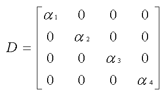
대각 행렬 D는 대각 성분이 각각 α1, α2, α3 및 α4 값을 갖는 행렬로서, 입력 음원의 각각의 구성 요소를 해당 α1, α2, α3 및 α4 만큼 스칼라 곱한 결과를 출력한다. 따라서, 수학식 5에서 대각 행렬 D를 승산한다는 것은 혼합 채널 A의 전달 함수의 크기가 특정 스칼라 값만큼 승산된 값으로 변하는 현상이 나타나는 것을 의미한다.The diagonal matrix D is a matrix having diagonal components α 1 , α 2 , α 3, and α 4 , respectively, and is a result of scalar multiplication of each component of the input sound source by the corresponding α 1 , α 2 , α 3 and α 4 Output. Therefore, multiplying the diagonal matrix D in Equation (5) means that the transfer function of the mixed channel A is changed to a value multiplied by a specific scalar value.
이러한 스케일링 모호성을 해결하기 위한 방법으로 추정된 분리 행렬 W에 대한 무어-펜로즈 일반화 역행렬(Moore-Penrose generalized inverse matrix)의 대각 성분들을 이용하는 방법이 다음의 수학식 8과 같이 알려져 있다. (N. Murata, S.Ikeda, and A. Ziehe, "An approach to blind source separation based on temporal structure of speech signals", Neurocomputing, Vol. 41, No. 1-4, pp. 1-24, Oct. 2001)A method of using the diagonal elements of the Moore-Penrose generalized inverse matrix for the separation matrix W estimated as a method for solving such scaling ambiguity is known as the following equation (8). (N. Murata, S. Ikeda, and A. Ziehe, "An approach to blind source separation based on temporal structure of speech signals", Neurocomputing, Vol. 41, No. 1-4, pp. 1-24, Oct. 2001)

수학식 8에서 무어-펜로즈 일반화 역행렬이란 각 구성 성분의 크기를 정규화된(nomalized) 1로 만드는 방법을 통해 스케일링 모호성을 해결한다. 특히 무어-펜로즈 일반화 역행렬은 일반적으로 행과 열의 숫자가 같아야 역행렬을 용이하게 구할 수 있는 것과는 달리, 행과 열의 숫자가 다른 경우(즉, 어레이를 구성하는 마이크로폰들의 수와 음원 신호의 수가 다른 경우를 의미한다.)에도 적용이 가능하다는 장점이 있다.In Equation (8), the Moore-Penrose generalized inverse matrix solves the scaling ambiguity by making the size of each component equal to a nomalized one. In particular, the Moore-Penrose generalized inverse matrix generally requires that the number of rows and columns be the same so that the inverse matrix can be easily obtained. In contrast, when the number of rows and columns is different (ie, the number of microphones constituting the array is different from the number of sound sources) It means that it is possible to apply to
따라서, 이상의 방법을 통해, 수학식 5에 나타난 치환 행렬 P와 대각 행렬 D의 성분을 제거함으로써 수학식 3과 같이 분리 채널 W의 역이 혼합 채널 A의 전달 함수를 근사화하도록 보정할 수 있다.Therefore, by removing the components of the permutation matrix P and the diagonal matrix D shown in Equation (5), the inverse of the separation channel W can be corrected to approximate the transfer function of the mixed channel A as shown in Equation (3).
도 4b는 본 발명의 일 실시예에 따른 음원 판별 장치에서 독립 음원으로부터 입력 신호를 추정하기 위해 치환 및 스케일링 모호성을 해결하는 구성을 도시한 도면으로서, 도 3에서 이미 설명한 음원 분리부(200)와 입력 신호 획득부(300) 이외에 추정 및 스케일링 모호성 해결부(permutation and scaling ambiguity solver)(250)를 추가하여 도시하였다.FIG. 4B illustrates a structure for solving substitution and scaling ambiguities for estimating an input signal from an independent sound source in a sound source discriminator according to an embodiment of the present invention. The
이상에서 설명한 바와 같이 추정 및 스케일링 모호성 해결부(250)는 분리된 독립 음원의 구성 요소의 순서가 치환되는 문제점과 전달 함수의 크기 결정이 모호해지는 문제점을 해결함으로써 분리 채널 W의 역인 W-1로 하여금 혼합 채널 A에 근접시킨다. 도 4b에서는 추정 및 스케일링 모호성 해결부(250)가 음원 분리부(200) 및 입력 신호 획득부(300)와는 별로의 블럭으로 도시되었으나, 이는 설명의 편의상 개념적인 블럭으로 도시한 것으로서, 음원 분리부(200)로부터 입력 신호 획득부(300)로 입력되는 분리 음원들(Y1, Y2, Y3 및 Y4)이 제대로 분리되기 위해서는 물리적으로 추정 및 스케일링 모호성 해결부(250)를 거쳐서 각각의 분리 음원들이 출력된다.By estimation and scaling
도 5는 본 발명의 일 실시예에 따른 혼합 사운드로부터의 음원 판별 방법을 도시한 흐름도로서 다음과 같은 단계들로 구성된다.5 is a flowchart illustrating a sound source discrimination method from a mixed sound according to an embodiment of the present invention, which comprises the following steps.
501 단계에서 마이크로폰 어레이를 통해 입력된 혼합 신호로부터 음원 신호들을 분리한다. 이러한 분리 과정은 상기 도 2 및 도 3의 음원 분리부(200)에서 설명한 바와 같이 ICA의 통계적인 음원 분리 과정을 통해 수행된다.In
502 단계에서 혼합 신호 및 분리된 음원 신호들의 관계로부터 복수 개의 음원들을 혼합하는 혼합 채널의 전달 함수를 추정한다. 이 과정은 상기 도 2의 전달 함수 추정부(350)에서 설명한 바와 같이 ICA의 학습 규칙을 이용하여 분리 채널을 결정하고, 결정된 분리 채널의 역을 구함으로써 수행된다. 이 과정에서 도 4a 및 도 4b에서 설명한 치환 및 스케일링 모호성 문제가 발생하고, 각각을 분리 행렬의 열 벡터를 정렬하는 방법과 분리 행렬의 역행렬의 대각 성분을 이용하는 방법을 통해 해결한다.In
503 단계에서 분리된 음원 신호들에 대해 마이크로폰 어레이의 입력 신호를 획득한다. 상기 도 2 및 도 3의 입력 신호 획득부(300)에서 설명한 바와 같이 마이크로폰 어레이의 입력 신호는 분리된 음원 신호에 503 단계에서 추정된 전달 함수를 승산함으로써 획득된다.In
504 단계에서 추정된 입력 신호에 기초하여 음원의 위치 정보를 산출한다. 각각의 음원별로 마이크로폰 어레이 신호 처리 분야에서 사용되는 다양한 음원 위치 추정 방법을 이용하여 음원의 방향 및 거리 정보 등의 음원의 위치 정보를 산출한다.The location information of the sound source is calculated based on the input signal estimated in
이상의 과정을 통하여 혼합 음원에 포함된 각각의 음원들을 판별하는 것이 가능하다. 이하에서는 판별된 음원 신호들을 활용하는 추가적인 실시예로서 음질을 개선하는 방법을 제시한다.Through the above process, it is possible to identify each sound source included in the mixed sound source. Hereinafter, a method for improving the sound quality is disclosed as an additional embodiment utilizing the discriminated sound source signals.
505 단계에서는 산출된 위치 정보를 이용하여 음원의 신호 대 잡음비를 개선함으로써 음질을 향상시킨다. 이를 위해 504 단계에서 산출된 분리된 음원 신호를 거리나 방향 정보에 따라 특정 순서로 정렬함으로써 사용자가 원하는 거리나 방향에 위치한 음원에 해당하는 특정 음원 신호들만 취사 선택하거나, 특정 음원 신호들을 마이크로폰 어레이의 다양한 빔 형성 알고리즘을 통해 음질을 개선하거나 음량을 크게 하는 등의 조작이 가능하다.In
이상에서 본 발명에 대한 다양한 실시예들을 중심으로 살펴보았다. 본 발명 에 속하는 기술 분야에서 통상의 지식을 가진 자는 본 발명이 본 발명의 본질적인 특성에서 벗어나지 않는 범위에서 변형된 형태로 구현될 수 있음을 이해할 수 있을 것이다. 그러므로 개시된 실시예들은 한정적인 관점이 아니라 설명적인 관점에서 고려되어야 한다. 본 발명의 범위는 전술한 설명이 아니라 특허청구범위에 나타나 있으며, 그와 동등한 범위 내에 있는 모든 차이점은 본 발명에 포함된 것으로 해석되어야 할 것이다.Various embodiments of the present invention have been described above. It will be understood by those skilled in the art that various changes in form and details may be made therein without departing from the spirit and scope of the invention as defined by the appended claims. Therefore, the disclosed embodiments should be considered in an illustrative rather than a restrictive sense. The scope of the present invention is defined by the appended claims rather than by the foregoing description, and all differences within the scope of equivalents thereof should be construed as being included in the present invention.
도 1은 본 발명이 해결하려는 문제의 상황과 이를 해결하기 위한 장치를 개념적으로 도시한 도면이다.BRIEF DESCRIPTION OF THE DRAWINGS Fig. 1 is a view conceptually showing a situation of a problem to be solved by the present invention and an apparatus for solving the problem. Fig.
도 2는 본 발명의 일 실시예에 따른 혼합 사운드로부터의 음원 판별 장치를 도시한 블럭도이다.FIG. 2 is a block diagram showing a sound source discriminating apparatus from a mixed sound according to an embodiment of the present invention.
도 3은 도 2에 도시한 본 발명의 일 실시예에 따른 음원 판별 장치에서 각각의 구성을 좀 더 구체적으로 도시한 블럭도이다.FIG. 3 is a block diagram showing a more detailed configuration of each of the sound source discriminating apparatuses according to the embodiment of the present invention shown in FIG.
도 4a는 본 발명의 일 실시예에 따른 음원 판별 장치에서 혼합 사운드로부터 독립 음원을 분리할 때 발생하는 치환 모호성(permutation ambiguity)을 도시한 도면이다.4A is a diagram illustrating permutation ambiguity generated when an independent sound source is separated from a mixed sound in the sound source discriminator according to an embodiment of the present invention.
도 4b는 본 발명의 일 실시예에 따른 음원 판별 장치에서 독립 음원으로부터 입력 신호를 추정하기 위해 치환 및 스케일링 모호성(permutation and scaling ambiguity)을 해결하는 구성을 도시한 도면이다.FIG. 4B is a diagram illustrating a structure for solving permutation and scaling ambiguity in order to estimate an input signal from an independent sound source in a sound source discriminator according to an embodiment of the present invention. Referring to FIG.
도 5는 본 발명의 일 실시예에 따른 혼합 사운드로부터의 음원 판별 방법을 도시한 흐름도이다.5 is a flowchart illustrating a sound source discrimination method from a mixed sound according to an embodiment of the present invention.
Claims (13)
Priority Applications (2)
| Application Number | Priority Date | Filing Date | Title |
|---|---|---|---|
| KR1020070098890A KR101434200B1 (en) | 2007-10-01 | 2007-10-01 | Method and apparatus for identifying sound source from mixed sound |
| US12/073,458 US20090086998A1 (en) | 2007-10-01 | 2008-03-05 | Method and apparatus for identifying sound sources from mixed sound signal |
Applications Claiming Priority (1)
| Application Number | Priority Date | Filing Date | Title |
|---|---|---|---|
| KR1020070098890A KR101434200B1 (en) | 2007-10-01 | 2007-10-01 | Method and apparatus for identifying sound source from mixed sound |
Publications (2)
| Publication Number | Publication Date |
|---|---|
| KR20090033716A KR20090033716A (en) | 2009-04-06 |
| KR101434200B1 true KR101434200B1 (en) | 2014-08-26 |
Family
ID=40508403
Family Applications (1)
| Application Number | Title | Priority Date | Filing Date |
|---|---|---|---|
| KR1020070098890A Expired - Fee Related KR101434200B1 (en) | 2007-10-01 | 2007-10-01 | Method and apparatus for identifying sound source from mixed sound |
Country Status (2)
| Country | Link |
|---|---|
| US (1) | US20090086998A1 (en) |
| KR (1) | KR101434200B1 (en) |
Families Citing this family (59)
| Publication number | Priority date | Publication date | Assignee | Title |
|---|---|---|---|---|
| US11431312B2 (en) | 2004-08-10 | 2022-08-30 | Bongiovi Acoustics Llc | System and method for digital signal processing |
| KR101597752B1 (en) * | 2008-10-10 | 2016-02-24 | 삼성전자주식회사 | Apparatus and method for noise estimation and noise reduction apparatus employing the same |
| KR101064976B1 (en) * | 2009-04-06 | 2011-09-15 | 한국과학기술원 | Sound source location estimation system and robot responding to sound source with same |
| WO2010125228A1 (en) * | 2009-04-30 | 2010-11-04 | Nokia Corporation | Encoding of multiview audio signals |
| JP5375400B2 (en) * | 2009-07-22 | 2013-12-25 | ソニー株式会社 | Audio processing apparatus, audio processing method and program |
| DE102009052992B3 (en) * | 2009-11-12 | 2011-03-17 | Institut für Rundfunktechnik GmbH | Method for mixing microphone signals of a multi-microphone sound recording |
| KR101086304B1 (en) | 2009-11-30 | 2011-11-23 | 한국과학기술연구원 | Apparatus and method for removing echo signals generated by robot platform |
| US10026407B1 (en) | 2010-12-17 | 2018-07-17 | Arrowhead Center, Inc. | Low bit-rate speech coding through quantization of mel-frequency cepstral coefficients |
| JP2012234150A (en) * | 2011-04-18 | 2012-11-29 | Sony Corp | Sound signal processing device, sound signal processing method and program |
| JP2012238964A (en) * | 2011-05-10 | 2012-12-06 | Funai Electric Co Ltd | Sound separating device, and camera unit with it |
| US20120294446A1 (en) * | 2011-05-16 | 2012-11-22 | Qualcomm Incorporated | Blind source separation based spatial filtering |
| JP2015506491A (en) * | 2011-12-29 | 2015-03-02 | インテル・コーポレーション | Acoustic signal correction |
| KR101367915B1 (en) * | 2012-01-10 | 2014-03-03 | 경북대학교 산학협력단 | Device and Method for Multichannel Speech Signal Processing |
| KR101348187B1 (en) * | 2012-05-10 | 2014-01-08 | 동명대학교산학협력단 | Collaboration monitering camera system using track multi audio source and operation method thereof |
| KR102008480B1 (en) * | 2012-09-21 | 2019-08-07 | 삼성전자주식회사 | Blind signal seperation apparatus and Method for seperating blind signal thereof |
| US9812150B2 (en) | 2013-08-28 | 2017-11-07 | Accusonus, Inc. | Methods and systems for improved signal decomposition |
| EP2854133A1 (en) * | 2013-09-27 | 2015-04-01 | Fraunhofer-Gesellschaft zur Förderung der angewandten Forschung e.V. | Generation of a downmix signal |
| US10468036B2 (en) | 2014-04-30 | 2019-11-05 | Accusonus, Inc. | Methods and systems for processing and mixing signals using signal decomposition |
| US20150264505A1 (en) | 2014-03-13 | 2015-09-17 | Accusonus S.A. | Wireless exchange of data between devices in live events |
| US9565493B2 (en) | 2015-04-30 | 2017-02-07 | Shure Acquisition Holdings, Inc. | Array microphone system and method of assembling the same |
| US9554207B2 (en) | 2015-04-30 | 2017-01-24 | Shure Acquisition Holdings, Inc. | Offset cartridge microphones |
| JP6606784B2 (en) * | 2015-09-29 | 2019-11-20 | 本田技研工業株式会社 | Audio processing apparatus and audio processing method |
| US20170209115A1 (en) * | 2016-01-25 | 2017-07-27 | Quattro Folia Oy | Method and system of separating and locating a plurality of acoustic signal sources in a human body |
| US11234072B2 (en) | 2016-02-18 | 2022-01-25 | Dolby Laboratories Licensing Corporation | Processing of microphone signals for spatial playback |
| US11152014B2 (en) | 2016-04-08 | 2021-10-19 | Dolby Laboratories Licensing Corporation | Audio source parameterization |
| CN105869627A (en) * | 2016-04-28 | 2016-08-17 | 成都之达科技有限公司 | Vehicle-networking-based speech processing method |
| US10249305B2 (en) * | 2016-05-19 | 2019-04-02 | Microsoft Technology Licensing, Llc | Permutation invariant training for talker-independent multi-talker speech separation |
| CN116612731A (en) | 2016-07-22 | 2023-08-18 | 杜比实验室特许公司 | Network-based processing and distribution of multimedia content for live musical performances |
| US10367948B2 (en) | 2017-01-13 | 2019-07-30 | Shure Acquisition Holdings, Inc. | Post-mixing acoustic echo cancellation systems and methods |
| US10587979B2 (en) * | 2018-02-06 | 2020-03-10 | Sony Interactive Entertainment Inc. | Localization of sound in a speaker system |
| US10523171B2 (en) * | 2018-02-06 | 2019-12-31 | Sony Interactive Entertainment Inc. | Method for dynamic sound equalization |
| US10957337B2 (en) | 2018-04-11 | 2021-03-23 | Microsoft Technology Licensing, Llc | Multi-microphone speech separation |
| WO2019231632A1 (en) | 2018-06-01 | 2019-12-05 | Shure Acquisition Holdings, Inc. | Pattern-forming microphone array |
| US11297423B2 (en) | 2018-06-15 | 2022-04-05 | Shure Acquisition Holdings, Inc. | Endfire linear array microphone |
| CN112889296B (en) | 2018-09-20 | 2025-01-10 | 舒尔获得控股公司 | Adjustable lobe shape for microphone arrays |
| US11558693B2 (en) | 2019-03-21 | 2023-01-17 | Shure Acquisition Holdings, Inc. | Auto focus, auto focus within regions, and auto placement of beamformed microphone lobes with inhibition and voice activity detection functionality |
| EP3942845A1 (en) | 2019-03-21 | 2022-01-26 | Shure Acquisition Holdings, Inc. | Auto focus, auto focus within regions, and auto placement of beamformed microphone lobes with inhibition functionality |
| WO2020191354A1 (en) | 2019-03-21 | 2020-09-24 | Shure Acquisition Holdings, Inc. | Housings and associated design features for ceiling array microphones |
| WO2020237206A1 (en) | 2019-05-23 | 2020-11-26 | Shure Acquisition Holdings, Inc. | Steerable speaker array, system, and method for the same |
| JP7731292B2 (en) | 2019-05-31 | 2025-08-29 | シュアー アクイジッション ホールディングス インコーポレイテッド | Integrated low latency automixer with voice and noise activity detection |
| CN112151061B (en) * | 2019-06-28 | 2023-12-12 | 北京地平线机器人技术研发有限公司 | Signal sorting method and device, computer-readable storage medium, electronic equipment |
| WO2021041275A1 (en) | 2019-08-23 | 2021-03-04 | Shore Acquisition Holdings, Inc. | Two-dimensional microphone array with improved directivity |
| CN110675892B (en) * | 2019-09-24 | 2022-04-05 | 北京地平线机器人技术研发有限公司 | Multi-position voice separation method and device, storage medium and electronic equipment |
| WO2021087377A1 (en) | 2019-11-01 | 2021-05-06 | Shure Acquisition Holdings, Inc. | Proximity microphone |
| US11552611B2 (en) | 2020-02-07 | 2023-01-10 | Shure Acquisition Holdings, Inc. | System and method for automatic adjustment of reference gain |
| CN111505583B (en) * | 2020-05-07 | 2022-07-01 | 北京百度网讯科技有限公司 | Sound source positioning method, device, equipment and readable storage medium |
| WO2021243368A2 (en) | 2020-05-29 | 2021-12-02 | Shure Acquisition Holdings, Inc. | Transducer steering and configuration systems and methods using a local positioning system |
| CN112116922B (en) * | 2020-09-17 | 2024-04-12 | 集美大学 | Noise blind source signal separation method, terminal equipment and storage medium |
| US11546689B2 (en) * | 2020-10-02 | 2023-01-03 | Ford Global Technologies, Llc | Systems and methods for audio processing |
| CN116918351A (en) | 2021-01-28 | 2023-10-20 | 舒尔获得控股公司 | Hybrid Audio Beamforming System |
| US12452584B2 (en) | 2021-01-29 | 2025-10-21 | Shure Acquisition Holdings, Inc. | Scalable conferencing systems and methods |
| KR102504043B1 (en) * | 2021-03-29 | 2023-02-28 | 한국광기술원 | Face-to-face Recording Apparatus and Method with Robust Dialogue Voice Separation in Noise Environments |
| US12542123B2 (en) | 2021-08-31 | 2026-02-03 | Shure Acquisition Holdings, Inc. | Mask non-linear processor for acoustic echo cancellation |
| EP4413745A1 (en) | 2021-10-04 | 2024-08-14 | Shure Acquisition Holdings, Inc. | Networked automixer systems and methods |
| EP4427465A1 (en) | 2021-11-05 | 2024-09-11 | Shure Acquisition Holdings, Inc. | Distributed algorithm for automixing speech over wireless networks |
| CN114333876B (en) * | 2021-11-25 | 2024-02-09 | 腾讯科技(深圳)有限公司 | Signal processing method and device |
| CN114167356B (en) * | 2021-12-06 | 2025-09-02 | 大连赛听科技有限公司 | A sound source localization method and system based on polyhedral microphone array |
| WO2023133513A1 (en) | 2022-01-07 | 2023-07-13 | Shure Acquisition Holdings, Inc. | Audio beamforming with nulling control system and methods |
| KR20250119575A (en) * | 2022-12-29 | 2025-08-07 | 엘지전자 주식회사 | Audio processing device and its operating method |
Citations (1)
| Publication number | Priority date | Publication date | Assignee | Title |
|---|---|---|---|---|
| US20050047611A1 (en) * | 2003-08-27 | 2005-03-03 | Xiadong Mao | Audio input system |
Family Cites Families (7)
| Publication number | Priority date | Publication date | Assignee | Title |
|---|---|---|---|---|
| US6625587B1 (en) * | 1997-06-18 | 2003-09-23 | Clarity, Llc | Blind signal separation |
| US7809145B2 (en) * | 2006-05-04 | 2010-10-05 | Sony Computer Entertainment Inc. | Ultra small microphone array |
| JP3881367B2 (en) * | 2003-03-04 | 2007-02-14 | 日本電信電話株式会社 | POSITION INFORMATION ESTIMATION DEVICE, ITS METHOD, AND PROGRAM |
| DE10339973A1 (en) * | 2003-08-29 | 2005-03-17 | Daimlerchrysler Ag | Intelligent acoustic microphone frontend with voice recognition feedback |
| US7099821B2 (en) * | 2003-09-12 | 2006-08-29 | Softmax, Inc. | Separation of target acoustic signals in a multi-transducer arrangement |
| JP2009529699A (en) * | 2006-03-01 | 2009-08-20 | ソフトマックス,インコーポレイテッド | System and method for generating separated signals |
| US8521477B2 (en) * | 2009-12-18 | 2013-08-27 | Electronics And Telecommunications Research Institute | Method for separating blind signal and apparatus for performing the same |
-
2007
- 2007-10-01 KR KR1020070098890A patent/KR101434200B1/en not_active Expired - Fee Related
-
2008
- 2008-03-05 US US12/073,458 patent/US20090086998A1/en not_active Abandoned
Patent Citations (1)
| Publication number | Priority date | Publication date | Assignee | Title |
|---|---|---|---|---|
| US20050047611A1 (en) * | 2003-08-27 | 2005-03-03 | Xiadong Mao | Audio input system |
Non-Patent Citations (2)
| Title |
|---|
| Futoshi Asano et al., ‘A combined approach of array processing and independent component analysis for blind separation of acoustic signals’, ICASSP 2001, Vol.5, pp.2729~2732, 2001* |
| Futoshi Asano et al., 'A combined approach of array processing and independent component analysis for blind separation of acoustic signals', ICASSP 2001, Vol.5, pp.2729~2732, 2001 * |
Also Published As
| Publication number | Publication date |
|---|---|
| US20090086998A1 (en) | 2009-04-02 |
| KR20090033716A (en) | 2009-04-06 |
Similar Documents
| Publication | Publication Date | Title |
|---|---|---|
| KR101434200B1 (en) | Method and apparatus for identifying sound source from mixed sound | |
| US20210089967A1 (en) | Data training in multi-sensor setups | |
| RU2596592C2 (en) | Spatial audio processor and method of providing spatial parameters based on acoustic input signal | |
| JP6454916B2 (en) | Audio processing apparatus, audio processing method, and program | |
| JP5305743B2 (en) | Sound processing apparatus and method | |
| US20090222262A1 (en) | Systems And Methods For Blind Source Signal Separation | |
| US20180277140A1 (en) | Signal processing system, signal processing method and storage medium | |
| Scheibler | SDR—medium rare with fast computations | |
| CN111863015A (en) | Audio processing method and device, electronic equipment and readable storage medium | |
| Rao et al. | A denoising approach to multisensor signal estimation | |
| JP5406866B2 (en) | Sound source separation apparatus, method and program thereof | |
| JP4529611B2 (en) | Voice input device | |
| JP6314475B2 (en) | Audio signal processing apparatus and program | |
| JP2020012976A (en) | Sound source separation evaluation device and sound source separation device | |
| Mokios et al. | Blind speech separation using parafac analysis and integer least squares | |
| CN113316075A (en) | Howling detection method and device and electronic equipment | |
| Gburrek et al. | On source-microphone distance estimation using convolutional recurrent neural networks | |
| Bai et al. | Acoustic source localization and deconvolution-based separation | |
| US10872619B2 (en) | Using images and residues of reference signals to deflate data signals | |
| CN113763982A (en) | Audio processing method and device, electronic equipment and readable storage medium | |
| JP7721089B2 (en) | Sound processing device, sound processing method and program | |
| RU2788939C1 (en) | Method and apparatus for defining a deep filter | |
| KR19980037008A (en) | A remote audio input device using a microphone array and its remote audio input processing method | |
| Nikunen et al. | Permutation alignment of frequency-domain ica by the maximization of intra-source envelope correlations | |
| CN108781317B (en) | Method and apparatus for detecting uncorrelated signal components using a linear sensor array |
Legal Events
| Date | Code | Title | Description |
|---|---|---|---|
| PA0109 | Patent application |
St.27 status event code: A-0-1-A10-A12-nap-PA0109 |
|
| PG1501 | Laying open of application |
St.27 status event code: A-1-1-Q10-Q12-nap-PG1501 |
|
| R18-X000 | Changes to party contact information recorded |
St.27 status event code: A-3-3-R10-R18-oth-X000 |
|
| A201 | Request for examination | ||
| PA0201 | Request for examination |
St.27 status event code: A-1-2-D10-D11-exm-PA0201 |
|
| P22-X000 | Classification modified |
St.27 status event code: A-2-2-P10-P22-nap-X000 |
|
| E902 | Notification of reason for refusal | ||
| PE0902 | Notice of grounds for rejection |
St.27 status event code: A-1-2-D10-D21-exm-PE0902 |
|
| T11-X000 | Administrative time limit extension requested |
St.27 status event code: U-3-3-T10-T11-oth-X000 |
|
| T11-X000 | Administrative time limit extension requested |
St.27 status event code: U-3-3-T10-T11-oth-X000 |
|
| P11-X000 | Amendment of application requested |
St.27 status event code: A-2-2-P10-P11-nap-X000 |
|
| P13-X000 | Application amended |
St.27 status event code: A-2-2-P10-P13-nap-X000 |
|
| E701 | Decision to grant or registration of patent right | ||
| P22-X000 | Classification modified |
St.27 status event code: A-2-2-P10-P22-nap-X000 |
|
| PE0701 | Decision of registration |
St.27 status event code: A-1-2-D10-D22-exm-PE0701 |
|
| GRNT | Written decision to grant | ||
| PR0701 | Registration of establishment |
St.27 status event code: A-2-4-F10-F11-exm-PR0701 |
|
| PR1002 | Payment of registration fee |
St.27 status event code: A-2-2-U10-U11-oth-PR1002 Fee payment year number: 1 |
|
| PG1601 | Publication of registration |
St.27 status event code: A-4-4-Q10-Q13-nap-PG1601 |
|
| LAPS | Lapse due to unpaid annual fee | ||
| PC1903 | Unpaid annual fee |
St.27 status event code: A-4-4-U10-U13-oth-PC1903 Not in force date: 20170821 Payment event data comment text: Termination Category : DEFAULT_OF_REGISTRATION_FEE |
|
| PC1903 | Unpaid annual fee |
St.27 status event code: N-4-6-H10-H13-oth-PC1903 Ip right cessation event data comment text: Termination Category : DEFAULT_OF_REGISTRATION_FEE Not in force date: 20170821 |