KR101432184B1 - Precision ablating device - Google Patents
Precision ablating device Download PDFInfo
- Publication number
- KR101432184B1 KR101432184B1 KR1020137015476A KR20137015476A KR101432184B1 KR 101432184 B1 KR101432184 B1 KR 101432184B1 KR 1020137015476 A KR1020137015476 A KR 1020137015476A KR 20137015476 A KR20137015476 A KR 20137015476A KR 101432184 B1 KR101432184 B1 KR 101432184B1
- Authority
- KR
- South Korea
- Prior art keywords
- endoscope
- ablation
- ablation structure
- sheath
- ablation device
- Prior art date
- Legal status (The legal status is an assumption and is not a legal conclusion. Google has not performed a legal analysis and makes no representation as to the accuracy of the status listed.)
- Expired - Fee Related
Links
Images


Classifications
-
- A—HUMAN NECESSITIES
- A61—MEDICAL OR VETERINARY SCIENCE; HYGIENE
- A61B—DIAGNOSIS; SURGERY; IDENTIFICATION
- A61B18/00—Surgical instruments, devices or methods for transferring non-mechanical forms of energy to or from the body
- A61B18/04—Surgical instruments, devices or methods for transferring non-mechanical forms of energy to or from the body by heating
- A61B18/12—Surgical instruments, devices or methods for transferring non-mechanical forms of energy to or from the body by heating by passing a current through the tissue to be heated, e.g. high-frequency current
- A61B18/14—Probes or electrodes therefor
- A61B18/1492—Probes or electrodes therefor having a flexible, catheter-like structure, e.g. for heart ablation
-
- A—HUMAN NECESSITIES
- A61—MEDICAL OR VETERINARY SCIENCE; HYGIENE
- A61B—DIAGNOSIS; SURGERY; IDENTIFICATION
- A61B1/00—Instruments for performing medical examinations of the interior of cavities or tubes of the body by visual or photographical inspection, e.g. endoscopes; Illuminating arrangements therefor
- A61B1/00064—Constructional details of the endoscope body
- A61B1/00071—Insertion part of the endoscope body
- A61B1/0008—Insertion part of the endoscope body characterised by distal tip features
- A61B1/00082—Balloons
-
- A—HUMAN NECESSITIES
- A61—MEDICAL OR VETERINARY SCIENCE; HYGIENE
- A61B—DIAGNOSIS; SURGERY; IDENTIFICATION
- A61B1/00—Instruments for performing medical examinations of the interior of cavities or tubes of the body by visual or photographical inspection, e.g. endoscopes; Illuminating arrangements therefor
- A61B1/00064—Constructional details of the endoscope body
- A61B1/00071—Insertion part of the endoscope body
- A61B1/0008—Insertion part of the endoscope body characterised by distal tip features
- A61B1/00087—Tools
-
- A—HUMAN NECESSITIES
- A61—MEDICAL OR VETERINARY SCIENCE; HYGIENE
- A61B—DIAGNOSIS; SURGERY; IDENTIFICATION
- A61B1/00—Instruments for performing medical examinations of the interior of cavities or tubes of the body by visual or photographical inspection, e.g. endoscopes; Illuminating arrangements therefor
- A61B1/00142—Instruments for performing medical examinations of the interior of cavities or tubes of the body by visual or photographical inspection, e.g. endoscopes; Illuminating arrangements therefor with means for preventing contamination, e.g. by using a sanitary sheath
-
- A—HUMAN NECESSITIES
- A61—MEDICAL OR VETERINARY SCIENCE; HYGIENE
- A61B—DIAGNOSIS; SURGERY; IDENTIFICATION
- A61B1/00—Instruments for performing medical examinations of the interior of cavities or tubes of the body by visual or photographical inspection, e.g. endoscopes; Illuminating arrangements therefor
- A61B1/273—Instruments for performing medical examinations of the interior of cavities or tubes of the body by visual or photographical inspection, e.g. endoscopes; Illuminating arrangements therefor for the upper alimentary canal, e.g. oesophagoscopes, gastroscopes
- A61B1/2736—Gastroscopes
-
- A—HUMAN NECESSITIES
- A61—MEDICAL OR VETERINARY SCIENCE; HYGIENE
- A61B—DIAGNOSIS; SURGERY; IDENTIFICATION
- A61B17/00—Surgical instruments, devices or methods
- A61B17/22—Implements for squeezing-off ulcers or the like on inner organs of the body; Implements for scraping-out cavities of body organs, e.g. bones; for invasive removal or destruction of calculus using mechanical vibrations; for removing obstructions in blood vessels, not otherwise provided for
-
- A—HUMAN NECESSITIES
- A61—MEDICAL OR VETERINARY SCIENCE; HYGIENE
- A61B—DIAGNOSIS; SURGERY; IDENTIFICATION
- A61B17/00—Surgical instruments, devices or methods
- A61B17/32—Surgical cutting instruments
- A61B17/3205—Excision instruments
-
- A—HUMAN NECESSITIES
- A61—MEDICAL OR VETERINARY SCIENCE; HYGIENE
- A61B—DIAGNOSIS; SURGERY; IDENTIFICATION
- A61B18/00—Surgical instruments, devices or methods for transferring non-mechanical forms of energy to or from the body
- A61B18/18—Surgical instruments, devices or methods for transferring non-mechanical forms of energy to or from the body by applying electromagnetic radiation, e.g. microwaves
-
- A—HUMAN NECESSITIES
- A61—MEDICAL OR VETERINARY SCIENCE; HYGIENE
- A61B—DIAGNOSIS; SURGERY; IDENTIFICATION
- A61B18/00—Surgical instruments, devices or methods for transferring non-mechanical forms of energy to or from the body
- A61B18/02—Surgical instruments, devices or methods for transferring non-mechanical forms of energy to or from the body by cooling, e.g. cryogenic techniques
-
- A—HUMAN NECESSITIES
- A61—MEDICAL OR VETERINARY SCIENCE; HYGIENE
- A61B—DIAGNOSIS; SURGERY; IDENTIFICATION
- A61B17/00—Surgical instruments, devices or methods
- A61B17/00234—Surgical instruments, devices or methods for minimally invasive surgery
- A61B2017/00292—Surgical instruments, devices or methods for minimally invasive surgery mounted on or guided by flexible, e.g. catheter-like, means
- A61B2017/00296—Surgical instruments, devices or methods for minimally invasive surgery mounted on or guided by flexible, e.g. catheter-like, means mounted on an endoscope
-
- A—HUMAN NECESSITIES
- A61—MEDICAL OR VETERINARY SCIENCE; HYGIENE
- A61B—DIAGNOSIS; SURGERY; IDENTIFICATION
- A61B17/00—Surgical instruments, devices or methods
- A61B17/00234—Surgical instruments, devices or methods for minimally invasive surgery
- A61B2017/00292—Surgical instruments, devices or methods for minimally invasive surgery mounted on or guided by flexible, e.g. catheter-like, means
- A61B2017/003—Steerable
-
- A—HUMAN NECESSITIES
- A61—MEDICAL OR VETERINARY SCIENCE; HYGIENE
- A61B—DIAGNOSIS; SURGERY; IDENTIFICATION
- A61B18/00—Surgical instruments, devices or methods for transferring non-mechanical forms of energy to or from the body
- A61B2018/00315—Surgical instruments, devices or methods for transferring non-mechanical forms of energy to or from the body for treatment of particular body parts
- A61B2018/00482—Digestive system
-
- A—HUMAN NECESSITIES
- A61—MEDICAL OR VETERINARY SCIENCE; HYGIENE
- A61B—DIAGNOSIS; SURGERY; IDENTIFICATION
- A61B18/00—Surgical instruments, devices or methods for transferring non-mechanical forms of energy to or from the body
- A61B18/04—Surgical instruments, devices or methods for transferring non-mechanical forms of energy to or from the body by heating
- A61B2018/044—Surgical instruments, devices or methods for transferring non-mechanical forms of energy to or from the body by heating the surgical action being effected by a circulating hot fluid
- A61B2018/046—Surgical instruments, devices or methods for transferring non-mechanical forms of energy to or from the body by heating the surgical action being effected by a circulating hot fluid in liquid form
-
- A—HUMAN NECESSITIES
- A61—MEDICAL OR VETERINARY SCIENCE; HYGIENE
- A61B—DIAGNOSIS; SURGERY; IDENTIFICATION
- A61B18/00—Surgical instruments, devices or methods for transferring non-mechanical forms of energy to or from the body
- A61B18/04—Surgical instruments, devices or methods for transferring non-mechanical forms of energy to or from the body by heating
- A61B18/12—Surgical instruments, devices or methods for transferring non-mechanical forms of energy to or from the body by heating by passing a current through the tissue to be heated, e.g. high-frequency current
- A61B18/14—Probes or electrodes therefor
- A61B2018/1495—Electrodes being detachable from a support structure
-
- A—HUMAN NECESSITIES
- A61—MEDICAL OR VETERINARY SCIENCE; HYGIENE
- A61B—DIAGNOSIS; SURGERY; IDENTIFICATION
- A61B90/00—Instruments, implements or accessories specially adapted for surgery or diagnosis and not covered by any of the groups A61B1/00 - A61B50/00, e.g. for luxation treatment or for protecting wound edges
- A61B90/50—Supports for surgical instruments, e.g. articulated arms
Landscapes
- Health & Medical Sciences (AREA)
- Life Sciences & Earth Sciences (AREA)
- Surgery (AREA)
- Engineering & Computer Science (AREA)
- Public Health (AREA)
- Nuclear Medicine, Radiotherapy & Molecular Imaging (AREA)
- General Health & Medical Sciences (AREA)
- Veterinary Medicine (AREA)
- Biomedical Technology (AREA)
- Heart & Thoracic Surgery (AREA)
- Medical Informatics (AREA)
- Molecular Biology (AREA)
- Animal Behavior & Ethology (AREA)
- Physics & Mathematics (AREA)
- Optics & Photonics (AREA)
- Biophysics (AREA)
- Pathology (AREA)
- Radiology & Medical Imaging (AREA)
- Otolaryngology (AREA)
- Plasma & Fusion (AREA)
- Cardiology (AREA)
- Gastroenterology & Hepatology (AREA)
- Electromagnetism (AREA)
- Orthopedic Medicine & Surgery (AREA)
- Vascular Medicine (AREA)
- Surgical Instruments (AREA)
- Laser Surgery Devices (AREA)
Abstract
소화관 내의 비정상 점막을 처리하기 위한 장치가 제공된다. 이 장치는 내시경에 제거가능하게 결합되도록 구성된 절제 구조물 및 절제 구조물이 내시경에 대해 그리고 조직 표면을 향하여 이동하도록 하는 편향 기구를 포함한다.An apparatus for treating an abnormal mucosa in a digestive tract is provided. The apparatus includes a resection structure configured to removably engage the endoscope and a biasing mechanism to move the resection structure relative to the endoscope and toward the tissue surface.
Description
본 발명은 소화관 내의 조직을 제거하기 위한 의료 장치 및 이의 이용 방법에 관한 것이다.The present invention relates to a medical device for removing tissue in the digestive tract and a method of using the same.
사람의 식도의 주요 기능들 중 두 개는 섭취구(intake)로부터 위까지 음식을 운반하고 위장 내용물의 역유동을 방지하는 것이다. 역유동은 부분적으로 두 개의 식도 괄약근에 의해 방지되며, 이 식도 괄약근은 정상적으로 폐쇄되어 있으며 구별되는 실체가 아닌 기능적인 것이다. 특히, 하부 식도 괄약근은 정상적으로 부교감신경계 작용에 의해 하부 식도 괄약근이 이완되여 음식이 식도로부터 위로 통과하는 것을 허용할 때까지 폐쇄되어 있다. 크산텐 성분을 가지는 음료수, 기름진 음식 및 흡연과 같은 다양한 타입의 음식 및 다른 활동에 의해 식도 괄약근이 이완될 수 있다. 소정의 약 또는 제약은 또한 하부 식도 괄약근의 이완, 뿐만 아니라 국부적 손상 또는 근신경 장애와 같은 다른 문제점을 일으킬 수 있다.Two of the main functions of the human esophagus are to transport food from the intake to the stomach and prevent reverse flow of the gastric contents. Reverse flow is partially prevented by two esophageal sphincters, which are normally closed and functioning, not distinct, entities. In particular, the lower esophageal sphincter is normally closed until the lower esophageal sphincter is relaxed by parasympathetic action allowing the food to pass upward from the esophagus. The esophageal sphincter can be relaxed by various types of food and other activities, such as beverages with xanthan content, fatty foods and smoking. Certain drugs or constraints may also cause other problems such as relaxation of the lower esophageal sphincter, as well as local impairment or myofascial disorders.
그럼에도 불구하고, 이러한 어려움을 가지고 있는 환자는 연하 장애를 포함하는 임상 증세, 음식 삼키기에 대한 어려움, 뿐만 아니라 울화 및 다른 유사한 불평의 더욱 전형적인 증세가 존재할 수 있다. 이러한 성질의 재발 문제점은 종종 역류성 식도염으로 알려진 장애를 초래하며 이 역류성 식도염으로 알려진 장애는 식도의 부분과 위 또는 장 성분의 상호 작용에 의한 식도 점막 손상을 일으키며, 상기 식도의 부분은 상기 상호 작용을 경험하지 않는 조직을 가진다. 상술된 바와 같이, 이러한 문제점에 대한 원인 인자는 변화될 수 있다. 식도염은 점막 내층의 세포가 손상되어 종양의 위험에 있을 때 발생되는 배렛(Barrett)의 식도염으로 알려진, 전암 상태를 초래할 수 있다.
Nonetheless, patients with these difficulties may have clinical symptoms, including swallowing difficulties, difficulty in swallowing food, as well as more typical symptoms of coughing and other similar complaints. The recurrence of this nature often results in a disorder known as reflux esophagitis, and a disorder known as reflux esophagitis causes esophageal mucosal damage due to the interaction of gastric or intestinal components with portions of the esophagus, Have an organization that does not experience. As described above, the causal factors for this problem can be varied. Esophagitis can lead to a precancerous condition known as Barrett's esophagitis, which occurs when the cells in the mucosal layer are damaged and are at risk for the tumor.
예를 들어 2004년 1월 9일에 출원되고 동시 계류중이고 권리자가 같은 미국 출원 제 10/754,445호에서 설명된 바와 같이, 확장가능한 전극 지지부를 가지는 처리 카테터(treatment catheter)가 무선주파수(RF) 에너지를 이용하여 식도의 주변 영역을 처리하기 위해 이용될 수 있다. 성공할 때, 처리는 배렛의 식도염의 후형질 및 다른 손상 상피 세포가 실질적으로 없는 정상적인 점막 층의 재생을 초래한다.For example, a treatment catheter having an expandable electrode support, as described in U.S. Patent Application No. 10 / 754,445, filed January 9, 2004, and co-pending, May be used to treat the surrounding area of the esophagus. When successful, treatment results in regeneration of the normal mucosal layer, which is substantially absent from the somnolence of Barrett's esophagus and other injured epithelial cells.
그러나, 일부의 경우 이러한 무선주파수 제거 처리는 완전히 성공할 수 없으며 비정상적인 점막의 하나 또는 그 이상의 영역이 남아 있을 수 있다. 이와 달리, 일부 환자는 초기에 주변 제거가 아닌 선택적인 제거에 더 적절한 정상적인 점막의 작은 분리된 영역으로 의사에게 제시된다.However, in some cases this radio frequency cancellation process can not be completely successful and one or more regions of abnormal mucosa may remain. In contrast, some patients are presented to the physician as a small, isolated area of normal mucosa, which is more appropriate for selective removal, rather than initially perioperative removal.
일반적으로, 하나의 양태에서, 본 발명은 내시경의 말단부에 제거가능하게 결합되도록 구성된 절제 구조물이 포함한다. 상기 장치는 내시경에 대해 조직 표면을 향하여 절제 구조물을 이동시키도록 하는 편향 기구(deflection mechanism)를 포함한다.In general, in one aspect, the present invention includes a ablation structure configured to removably engage a distal end of an endoscope. The device includes a deflection mechanism for moving the ablation structure towards the tissue surface with respect to the endoscope.
본 발명의 실시예는 하나 또는 그 이상의 후술되는 특징을 포함한다. 절제 구조물은 복수의 전극을 포함할 수 있다. 상기 장치는 또한 내시경에 대해 절제 구조물을 이동하도록 하는 이동 기구를 포함한다. 상기 장치는 내시경을 구비한 절제 구조물과 결합하도록 내시경의 외측면 위에 조립되는 결합 기구를 포함할 수 있다.Embodiments of the invention include one or more of the following features. The ablation structure may include a plurality of electrodes. The device also includes a moving mechanism for moving the ablation structure relative to the endoscope. The device may include a coupling mechanism that is assembled onto the outer surface of the endoscope to engage a ablation structure having an endoscope.
상기 장치는 또한 절제 구조물을 내시경에 결합하기 위해 외측면 위에 펼쳐지도록 하는 시스(sheath)를 포함한다. 시스는 이와 달리 절제 구조물을 내시경으로 결합하도록 할 수 있다. 이러한 실시예에서, 시스는 시스의 근위부(proximal portion)에 형성되는 슬릿을 포함하며, 상기 슬릿은 내시경의 말단부가 시스 내로 들어갈 수 있도록 개방되도록 한다. 또 다른 실시예에서, 시스는 시스의 근위부 보다 더 작은 외경을 구비한 말단 부분(distal portion)을 포함할 수 있으며, 시스의 말단 부분은 내시경이 삽입될 때 확장되도록 한다.The device also includes a sheath that allows the ablation structure to unfold onto the outer surface for engaging the endoscope. SIS, on the other hand, may allow the ablation structure to be coupled to the endoscope. In this embodiment, the sheath includes a slit formed in the proximal portion of the sheath, such that the slit opens to allow the distal end of the endoscope to enter the sheath. In another embodiment, the sheath can include a distal portion having a smaller outer diameter than the proximal portion of the sheath, and the distal portion of the sheath expands when the endoscope is inserted.
상기 장치는 내시경에 결합될 때 절제 구조물이 내시경에 대해 피봇되도록 한다. 결합 기구는 링을 포함하며 절제 구조물은 링을 중심으로 피봇되도록 한다. 또 다른 실시예에서, 결합 기구는 절제 구조물이 피봇되도록 하기 위해 플렉싱되도록 하는 탄성 밴드를 포함할 수 있다. 상기 장치의 결합 기구는 내시경과 절제 구조물을 결합하도록 내시경의 채널 내에 조립되도록 할 수 있다.The device allows the ablation structure to pivot relative to the endoscope when coupled to the endoscope. The coupling mechanism comprises a ring and the ablation structure pivots about the ring. In another embodiment, the coupling mechanism may include an elastic band that is flexed to pivot the ablation structure. The coupling mechanism of the device may be assembled in the channel of the endoscope to join the endoscope and the ablation structure.
상기 장치가 결합 기구를 포함할 때, 상기 장치의 절제 구조물이 내시경 채널 내에 조립되도록 할 수 있다. 또한, 편향 기구는 내시경 채널 내에 조립될 수 있다. 일 실시예에서, 절제 구조물은 편향 기구 상에 장착된다. 일 실시예에서, 결합 기구는 형상 기억 부재를 포함하며 편향 기구는 형상 기억 부재의 벤딩 부분을 포함한다.When the device includes a coupling mechanism, it may be possible for the ablation structure of the device to be assembled in the endoscope channel. Further, the biasing mechanism can be assembled in the endoscope channel. In one embodiment, the ablation structure is mounted on the biasing mechanism. In one embodiment, the coupling mechanism includes a shape memory member and the biasing mechanism includes a bending portion of the shape memory member.
본 발명의 실시예는 하나 또는 그 이상의 후술되는 특징을 포함할 수 있다. 절제 구조물은 추가적으로 제 1 형상으로부터 제 1 반경 방향 확장 형상으로 이동하도록 한다. 일 실시예에서, 상기 장치는 절제 구조물이 제 1 형상으로부터 제 2 형상으로 이동하도록 하는 절제 구조물 액츄에이터를 더 포함한다.Embodiments of the invention may include one or more of the following features. The ablation structure further allows movement from the first configuration to the first radially expanded configuration. In one embodiment, the apparatus further comprises a ablation structure actuator for causing the ablation structure to move from the first shape to the second shape.
상기 장치의 편향 구조물은 팽창가능한 부재(inflatable member) 및/또는 확장가능한 부재(expandable member)를 포함할 수 있다.The deflection structure of the device may comprise an inflatable member and / or an expandable member.
본 발명의 실시예는 하나 또는 그 이상의 후술되는 특징을 포함할 수 있다. 상기 장치는 내시경의 중심 축선을 중심으로 상기 절제 구조물이 회전하도록 토크가 내시경의 말단부로부터 절제 구조물로 전달되도록 하는 토크 전달 부재를 포함할 수 있다. 토크 전달 부재는 중심 축선을 중심으로 절제 구조물과 내시경 사이의 상대적인 회전 운동을 방지하도록 하는 제 1 및 제 2 인터록킹 부재(interlocking member)를 포함할 수 있다. 제 1 인터록킹 부재는 키(key)일 수 있으며 제 2 인터록킹 부재는 키웨이(keyway)일 수 있다. 일 실시예에서, 제 1 인터록킹 부재는 내시경 둘레의 시스에 부착되고 제 2 인터록킹 부재는 절제 구조물을 지지하는 카테터(catheter)에 부착된다. 추가 실시예에서, 카테터 및 시스는 중심 축선을 따른 상대적인 이동을 위해 적용된다.Embodiments of the invention may include one or more of the following features. The apparatus may include a torque transmitting member that allows torque to be transmitted from the distal end of the endoscope to the ablation structure such that the ablation structure rotates about a central axis of the endoscope. The torque transmitting member may include first and second interlocking members to prevent relative rotational movement between the ablation structure and the endoscope about a central axis. The first interlocking member may be a key and the second interlocking member may be a keyway. In one embodiment, the first interlocking member is attached to the sheath around the endoscope and the second interlocking member is attached to a catheter that supports the ablation structure. In a further embodiment, the catheter and sheath are applied for relative movement along the central axis.
또 다른 양태에서, 본 발명은 절제 구조물을 소화관 내로 전진시키는 단계, 내시경을 구비한 절제 구조물을 소화관 내에 지지하는 단계, 내시경에 대해 및 조직 표면을 향하여 절제 구조물의 적어도 일 부분을 이동시키는 단계, 및 조직 표면을 제거하기 위하여 절제 구조물을 작동시키는 단계를 포함하는, 소화관 내의 조직을 제거하는 방법을 특징으로 한다.In another aspect, the present invention provides a method of treating a gastrointestinal tract, comprising advancing a resection structure into the digestive tract, supporting a resection structure having an endoscope in the digestive tract, moving at least a portion of the resection structure with respect to the endoscope, And removing the tissue in the digestive tract, including operating the ablation structure to remove the tissue surface.
본 발명의 실시예는 하나 또는 그 이상의 아래 특징을 포함할 수 있다. 절제 구조물은 복수의 전극을 포함할 수 있으며 작동 단계는 전극으로 에너지를 인가하는 단계를 포함할 수 있다. 소화관 내로 절제 구조물을 전진시키는 단계는 소화관 내로 내시경을 전진시키는 단계 및 내시경 위로 절제 구조물을 전진시키는 단계를 포함할 수 있다. 절제 구조물을 지지하는 단계는 절제 구조물 내로 내시경을 삽입하는 단계를 포함할 수 있다. 일 실시예에서, 절제 구조물은 시스에 의해 지지되고, 절제 구조물 내로 내시경을 삽입하는 단계는 시스 내로 내시경을 삽입하는 단계를 포함할 수 있다. 또한, 시스 내로 내시경을 삽입하는 단계는 시스 내에 개구를 형성하는 단계를 포함할 수 있다.Embodiments of the invention may include one or more of the following features. The ablation structure may include a plurality of electrodes and the actuation step may include applying energy to the electrodes. Advancing the ablation structure into the digestive tract may include advancing the endoscope into the digestive tract and advancing the abdominal structure over the endoscope. Supporting the ablation structure may include inserting the endoscope into the ablation structure. In one embodiment, the ablation structure is supported by a sheath, and inserting the endoscope into the ablation structure may include inserting the endoscope into the sheath. In addition, inserting the endoscope into the sheath may include forming an opening in the sheath.
절제 구조물을 소화관 내로 전진하는 단계는 선택적으로 내시경의 채널을 통하여 절제 구조물을 전진하는 단계를 포함할 수 있다. 절제 구조물을 지지하는 단계는 내시경의 채널을 이용하여 절제 구조물을 지지하는 단계를 포함할 수 있다.Advancing the ablation structure into the digestive tract may optionally include advancing the ablation structure through a channel of the endoscope. Supporting the ablation structure may include supporting the ablation structure using a channel of the endoscope.
본 발명의 실시예는 하나 또는 그 이상의 아래 특징을 포함할 수 있다. 소화관 내의 조직을 제거하는 방법은 내시경의 채널을 통하여 편향 부재를 전진하는 단계를 더 포함한다. 더욱이, 절제 구조물의 일 부분을 이동하는 단계는 편향 부재를 이용하여 절제 구조물을 편향시키는 단계를 포함할 수 있다. 일 실시예에서, 이동하는 단계는 소화관 내에 팽창 부재를 부풀리게 하는 단계를 포함한다. 또 다른 실시예에서, 이동 단계는 편향 부재를 확장하는 단계를 포함한다. 추가 실시예에서, 이동하는 단계는 편향 부재를 이동시키는 단계를 포함한다. 또 다른 실시예에서, 이동 단계는 내시경에 대해 절제 구조물을 피봇하는 단계를 포함한다.Embodiments of the invention may include one or more of the following features. The method of removing tissue within the digestive tract further comprises advancing the biasing member through the channel of the endoscope. Moreover, the step of moving a portion of the ablation structure may include deflecting the ablation structure using a biasing member. In one embodiment, the moving step includes inflating the inflation member in the digestive tract. In yet another embodiment, the moving step includes extending the biasing member. In a further embodiment, the moving step comprises moving the biasing member. In yet another embodiment, the moving step includes pivoting the ablation structure against the endoscope.
본 발명의 실시예는 하나 또는 그 이상의 후술되는 특징을 부가적으로 포함할 수 있다. 소화관 내에서 조직을 제거하는 방법은 제 1 형상으로부터 제 2 반경 방향 확장 형상으로 절제 구조물을 확장하는 단계를 포함할 수 있다. 일 실시예에서, 본 발명의 방법은 엘라스토머 시스를 이용하여 절제 구조물을 내시경에 부착하는 단계를 더 포함할 수 있다. 또 다른 실시예에서, 절제 구조물은 감겨진(rolling) 시스에 부착되고 상기 방법은 내시경의 외측면 위에 시스를 펼치는(unrolling) 단계를 더 포함한다. 관련된 일 실시예에서, 펼치는 단계는 절제 구조물의 부분 위에 시스를 펼치는 단계를 더 포함한다.Embodiments of the invention may additionally include one or more of the following features. The method of removing tissue within the digestive tract may include extending the resection structure from the first shape to the second radially extending shape. In one embodiment, the method of the present invention may further comprise attaching the ablation structure to the endoscope using an elastomeric sheath. In another embodiment, the ablation structure is attached to a rolling sheath and the method further comprises unrolling the sheath on the outer surface of the endoscope. In one related embodiment, the step of unfolding further comprises the step of unfolding the sheath on the portion of the ablation structure.
본 발명의 실시예는 하나 또는 그 이상의 아래 특징을 더 포함할 수 있다. 절제 구조물은 내시경의 채널에 부착될 수 있다. 제거되는 조직 표면은 제 1 처리 영역을 포함할 수 있으며, 상기 인가 단계는 제 1 처리 영역을 제거하도록 절제 구조물을 작동시키는 단계를 포함하며, 상기 방법은 환자로부터 절제 구조물을 제거하지 않고 절제 구조물을 제 2 영역으로 이동시키는 단계 및 제 2 조직 영역을 제거하기 위해 절제 구조물을 작동시키는 단계를 더 포함한다.Embodiments of the present invention may further include one or more of the following features. The ablation structure may be attached to the channel of the endoscope. The tissue surface to be removed may comprise a first treatment area, said applying step comprising activating the ablation structure to remove the first treatment area, said method comprising: removing the ablation structure from the patient, Moving to a second region and actuating the ablation structure to remove a second tissue region.
일반적으로, 또 다른 양태에서, 본 발명은 소화관 내로 절제 구조물을 전진시키는 단계, 소화관 내에 내시경으로 절제 구조물을 지지하는 단계, 절제 구조물을 이동시켜 조직 표면과 접촉하도록 내시경의 말단부를 벤딩하는 단계, 및 조직 표면을 제거하도록 절제 구조물을 작동시키는 단계를 포함하는, 소화관 내의 조직을 제거하는 방법을 특징으로 한다.Generally, in another aspect, the present invention provides a method of treating a gastrointestinal tract, comprising advancing a resection structure into the digestive tract, supporting the resection structure with an endoscope in the digestive tract, moving the resection structure to bend the distal end of the endoscope to contact the tissue surface, And removing the tissue in the digestive tract, comprising the step of actuating the ablation structure to remove the tissue surface.
본 발명의 실시예는 하나 또는 그 이상의 아래 특징을 더 포함할 수 있다. 상기 방법은 내시경에 대해 절제 구조물을 이동시키는 단계를 더 포함할 수 있다. 이동 단계는 내시경에 대해 절제 구조물을 피봇팅하는 단계를 포함할 수 있다. 일 실시예에서, 이동 단계는 내시경으로부터 반지름방향 외측으로 절제 구조물을 이동시키는 단계를 포함한다. 관련된 실시예에서, 조직 표면은 제 1 처리 영역을 포함하며, 작동 단계는 제 1 처리 영역을 제거하기 위하여 절제 구조물을 작동시키는 단계를 포함하며, 상기 방법은 환자로부터 절제 구조물을 제거하지 않고 제 2 영역으로 절제 구조물을 이동시키는 단계 및 제 2 조직 영역을 제거하기 위하여 절제 구조물을 작동시키는 단계를 더 포함한다. 일 실시예에서, 절제 구조물은 복수의 전극을 포함하고 작동 단계는 전극으로 에너지를 인가하는 단계를 포함한다.Embodiments of the present invention may further include one or more of the following features. The method may further comprise moving the ablation structure relative to the endoscope. The moving step may include pivoting the ablation structure against the endoscope. In one embodiment, the moving step comprises moving the ablation structure radially outwardly from the endoscope. In a related embodiment, the tissue surface comprises a first treatment area, and the actuation step comprises activating the ablation structure to remove the first treatment area, the method comprising: removing the ablation structure from the patient, Moving the ablation structure into the region and actuating the ablation structure to remove the second tissue region. In one embodiment, the ablation structure includes a plurality of electrodes and the actuation step comprises applying energy to the electrodes.
참조 문헌References
본원 발명의 명세서에서 언급된 모든 공보 및 특허 출원은 각각의 개별 공보 또는 특허 출원이 참조되도록 특별히 그리고 개별적으로 표시되는 경우와 동일한 정도로 참조된다.All publications and patent applications mentioned in the specification are herein incorporated by reference to the same extent as if each individual publication or patent application was specifically and individually indicated to be incorporated by reference.
본 발명의 신규한 특징은 첨부된 청구범위에서 특별하게 제시된다. 본 발명의 특징 및 장점의 이해가 본 발명의 원리가 이용되는 예시적인 실시예 및 첨부된 도면이 제시되는 아래의 상세한 설명을 참조함으로써 용이하게 된다.The novel features of the invention are set forth with particularity in the appended claims. An understanding of the features and advantages of the present invention is facilitated by reference to the following detailed description, in which exemplary embodiments in which the principles of the invention are employed and the accompanying drawings are presented.
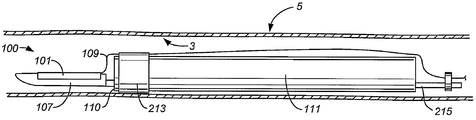
도 1은 본 발명의 절제 장치의 도면이고,
도 2는 본 발명의 절제 장치의 단부도이고,
도 3은 확대된 형태의 절제 장치의 단부도이고,
도 4는 상기 장치의 결합 기구의 도면이고,
도 5는 다른 결합 기구를 보여주는 본 발명의 절제 장치의 도면이고,
도 6, 도 7, 및 도 8은 다른 확대 형상의 상기 절제 장치의 단부도이고,
도 9는 확대되지 않은 형상의 본 발명의 절제 장치의 도면이고,
도 10은 확대된 형상의 본 발명의 절제 장치의 도면이고,
도 11 및 도 12는 확대된 형태의 절제 장치의 단부도이고,
도 13은 편향 부재 구성을 보여주는 본 발명의 절제 장치의 도면이고,
도 14는 다른 편향 부재를 보여주는 본 발명의 절제 장치의 도면으로서, 상기 장치는 확대 형태인, 도면이고,
도 15는 편향 부재가 확장되지 않은 형상에 있는 도 14에 도시된 장치의 도면이고,
도 16은 확장되지 않은 형상의 상기 장치의 단부도이고,
도 17은 확장 형상으로 도 16에 도시된 장치의 단부도이고,
도 18은 절제 구조물 피쳐를 보여주는 본 발명의 절제 장치의 도면이고,
도 19는 내시경 시스템과 조합된 본 발명의 절제 장치의 도면이고,
도 20은 비정상적인 점막을 포함하는 식도를 보여주는, 사람의 상부 소화관의 부분을 보여주는 도면이고,
도 21은 식도 내에 위치하는 본 발명의 절제 장치의 도면이고,
도 22는 긴 시스 피쳐를 포함하는 본 발명의 절제 장치의 도면이고,
도 23은 긴 시스 피쳐가 광학적으로 투과성인 장치의 도면이고,
도 24는 도 23에 도시된 장치의 광학 투과성 피쳐의 확대도이고,
도 25는 도 23 및 24에 도시된 장치의 광학 투과성 피쳐의 단면도이고,
도 26은 다른 광학 투과성 시스 피쳐 및 확장된 형상으로 있는 팽창 부재 피쳐를 포함하는 장치의 도면이고,
도 27은 식도 내에 위치하는 도 26의 절제 장치의 도면이고,
도 28은 가요성 팁 피쳐를 포함하는 본 발명의 절제 장치의 도면이고,
도 29는 슬릿 시스 피쳐를 포함하는 본 발명의 절제 장치의 도면이고,
도 30a는 시스가 확장되지 않은 형상에 있는 장치의 슬릿 시스 피쳐의 단부도이고,
도 30b는 상기 장치의 슬릿 시스 피쳐의 단부도로서, 시스가 확장 형상에 있는 도면이고,
도 31은 긴 시스 피쳐 및 내시경을 포함하는 본 발명의 절제 장치의 도면이고,
도 32는 도 31의 말단 부분 장치의 확대도이고,
도 33a는 내시경 내부 작업 채널 내에 위치하는 장치의 단면도로서, 팽창 부재 피쳐는 확장되지 않은 위치에 있는 도면이고,
도 33b는 도 33에 도시된 상기 장치의 도면으로서, 상기 팽창 부재 피쳐는 팽창 가능한 위치에 있는 도면이고,
도 34a는 내시경 내부 작업 채널 내에 위치하는 상기 장치의 단면도로서, 확장가능한 부재 피쳐는 확장되지 않은 위치에 있는 도면이고,
도 34b는 도 34a에 도시된 장치의 도면으로서, 확장가능한 부재 피쳐는 확장가능한 위치에 있는 도면이고,
도 35a는 내시경 내부 작업 채널 내에 위치설정되는 장치의 단면도로서, 다른 확장가능한 부재 피쳐가 팽창되지 않은 위치에 있는 도면이고,
도 35b는 확장 부재 피쳐가 확장 위치에 있는 도 35a에 도시된 장치의 도면이고,
도 36은 다른 편향 부재를 포함하는 본 발명의 절제 장치의 도면이고,
도 37은 비 편향 상태로 식도 내에 위치하는 다른 편향 부재를 포함하는 본 발명의 절제 장치의 도면이고,
도 38은 도 37에 도시된 장치의 도면으로서, 편향 부재는 편향 위치에 있는 도면이고,
도 39는 내부 결합 기구 피쳐를 보여주는 본 발명의 절제 장치의 단면도이고,
도 40은 다른 내부 결합 기구 및 감겨진 시스 피쳐를 보여주는 본 발명의 절제 장치의 단면도이고,
도 41은 식도 내에 위치하는 본 발명의 절제 장치의 단면도이고,
도 42는 회전가능한 피쳐를 보여주는 식도 내에 위치하는 본 발명의 절제 장치의 도면이고,
도 43은 확장 형태로 있는 팽창 부재와 조합된 회전 피쳐를 보여주는 식도 내에 위치하는 본 발명의 절제 장치의 도면이고,
도 44a, 44b 및 44c는 다른 회전 피쳐를 보여주는 본 발명의 절제 장치의 도면이고,
도 45a는 내시겨의 도면이고,
도 45b는 카테터 피쳐를 포함하는 본 발명의 절제 장치의 도면이고,
도 45c는 상기 장치의 시스 피쳐의 도면이고,
도 46은 하나의 조립체 내에 도 45a, 45b 및 도 45c에 도시된 피쳐를 포함하는 본 발명의 절제 장치의 도면이다.1 is a view of the ablation apparatus of the present invention,
2 is an end view of the ablation device of the present invention,
3 is an end view of the ablation device in an enlarged form,
Figure 4 is a view of the coupling mechanism of the device,
Figure 5 is a view of the ablation device of the present invention showing another coupling mechanism,
Figures 6, 7 and 8 are end views of the ablation device of another enlarged configuration,
Figure 9 is a view of the ablation device of the present invention in an unexpanded configuration,
Figure 10 is a view of the ablation device of the invention in its enlarged configuration,
11 and 12 are end views of the ablation device in an enlarged form,
13 is a view of the ablation device of the present invention showing the configuration of the biasing member,
Figure 14 is a drawing of the ablation device of the present invention showing another biasing member, the device being an enlarged view,
Figure 15 is a view of the device shown in Figure 14 with the biasing member in its non-expanded configuration,
Figure 16 is an end view of the device in its unexpanded configuration,
Figure 17 is an end view of the apparatus shown in Figure 16 in an expanded configuration,
Figure 18 is a view of the ablation device of the present invention showing ablation structure features,
Figure 19 is a view of the ablation device of the present invention in combination with an endoscopic system,
Figure 20 is a view showing a portion of a human upper gastrointestinal tract showing an esophagus containing abnormal mucosa,
Figure 21 is a view of the ablation device of the present invention located within the esophagus,
22 is a view of the ablation apparatus of the present invention including a long cis-feature,
23 is a view of an apparatus in which a long cis feature is optically transmissive,
Figure 24 is an enlarged view of the optically transmissive feature of the device shown in Figure 23,
Figure 25 is a cross-sectional view of the optically transmissive feature of the device shown in Figures 23 and 24,
Figure 26 is a view of an apparatus comprising an expanding member feature in an alternative optical transmissive sheath feature and an expanded shape,
Figure 27 is a view of the ablation device of Figure 26 located in the esophagus,
Figure 28 is a view of the ablation device of the present invention including a flexible tip feature,
29 is a view of the ablation apparatus of the present invention including a slit-sise feature,
30A is an end view of a slit-sheath feature of an apparatus in which the sheath is in an unexpanded configuration,
30B is an end view of the slit sheath feature of the apparatus, in which the sheath is in an expanded configuration,
31 is a view of a resection apparatus of the present invention including a long cis feature and an endoscope,
Fig. 32 is an enlarged view of the end portion device of Fig. 31,
33A is a cross-sectional view of an apparatus positioned within an endoscopic internal working channel, wherein the expansion member feature is in a non-expanded position,
33B is a view of the apparatus shown in FIG. 33, wherein the expansion member feature is in an inflatable position,
34A is a cross-sectional view of the device positioned within an endoscopic internal working channel, wherein the expandable member feature is in an unexpanded position,
34B is a view of the apparatus shown in FIG. 34A, in which the expandable member features are in an expandable position,
35A is a cross-sectional view of an apparatus positioned within an endoscopic internal working channel, with another expandable member feature in a non-inflated position,
35B is a view of the apparatus shown in FIG. 35A, in which the extension member features are in the extended position,
36 is a view of the ablation device of the present invention including another biasing member,
37 is a view of the ablation device of the present invention including another biasing member positioned in the esophagus in a non-biased state,
FIG. 38 is a view of the apparatus shown in FIG. 37, in which the biasing member is in the biased position,
39 is a cross-sectional view of the ablation device of the present invention showing an inner coupling mechanism feature,
40 is a cross-sectional view of the ablation device of the present invention showing another interlocking mechanism and a wound cis feature,
41 is a sectional view of the ablation device of the present invention located in the esophagus,
Figure 42 is a view of the ablation device of the present invention located in the esophagus showing rotatable features,
Figure 43 is a view of the ablation device of the present invention located in the esophagus showing a rotational feature in combination with an expanding member in an expanded configuration,
Figures 44a, 44b and 44c are views of the ablation device of the present invention showing different rotation features,
FIG. 45A is a view of the endoscope,
45B is a view of the ablation device of the present invention including a catheter feature,
45c is a view of the cis-feature of the device,
Figure 46 is a view of the ablation device of the present invention including the features shown in Figures 45a, 45b and 45c in one assembly.
소화관 내의 조직을 제거하는 방법은 도 19에 도시된 바와 같이 종래의 내시경(111)에 의해 지지되는 절제 구조물을 포함하는 절제 장치의 이용을 포함한다. 하나의 상업적으로 이용가능한 종래의 내시경(111)의 일 예는 올림푸스(Olympus) "가스트로비디오스코프(gastrovideoscope) " 모델 제 GIF-Q 160호이다. 특별하게 상업적으로 이용가능한 내시경의 특정 구성은 도 19에 도시된 바와 같이, 변화될 수 있지만, 대부분의 내시경은 조종가능한 말단부(110) 및 허브 또는 핸들(162)을 가지는 샤프트(164)를 포함하며, 상기 허브 또는 핸들은 비디오 스크린(160)으로 연결하기 위한 시각 채널(161) 및 샤프트(164) 내의 내부 작동 채널로의 통로를 제공하는 포트(166)를 포함한다. 다이얼, 레버, 또는 다른 기구(도시안됨)는 항상 핸들(162) 상에 제공되어 조작자가 내시경 분야에 널리 알려진 바와 같이 내시경(111)의 말단부(11)를 선택적으로 조종하도록 한다. 본 발명에 따라, 절제 구조물을 포함하는 절제 장치는 소화관 내로 전진하고 내시경의 말단부에서 지지된다. 절제 구조물은 조직 표면을 향하여 편향가능하며 절제 구조물은 조직 표면을 제거하기 위하여 작동된다. 소화관 내에, 다양한 크기의 조직 표면 장소가 상기 장치를 이용하여 선택적으로 제거될 수 있다.The method for removing the tissue in the digestive tract includes the use of a resection device including a resection structure supported by a
일반적으로, 소화관 내에서 조직을 제거하는 방법이 제공된다. 상기 방법은 내시경으로 절제 장치를 지지하는 동안 소화관 내로 절제 구조물을 전진하는 단계를 포함한다. 상기 방법은 내시경에 대해 그리고 조직 표면을 향하여 절제 구조물의 적어도 일 부분을 이동하는 단계, 조직 표면을 제거하도록 절제 구조물을 작동시키는 단계를 더 포함한다. 내시경에 대한 절제 구조물의 적어도 일부분을 이동시키는 단계는 내시경을 향하여, 내시경으로부터 멀어지게 또는 내시경을 따른 이동으로 제한되지 않는다. 도 1,2,3 및 21은 하나의 양태에서 소화관 내에서 조직을 제거하는 방법이 조직 표면(3)을 제거하기 위한 절제 장치(100)를 포함하며, 절제 장치(100)는 절제 구조물, 예를 들면 내시경(111)에 의해 지지되는 절제 구조물(101)을 포함한다. 상기 방법은 1) 소화관 내로 절제 구조물(101)을 전진시키는 단계, 2) 조직 표면(3)을 향하여 절제 구조물(101)을 편향시키는 단계, 및 3) 조직 표면(3)을 제거하도록 절제 구조물을 작동시키는 단계에 의해, 소화관 내의 조직을 제거하는 단계를 포함한다. 도 1에 도시된 바와 같이, 상기 장치(100)는 하우징(107), 전기 연결부(109), 팽창 라인(113) 및 팽창 부재(105)를 부가적으로 포함할 수 있다. 이러한 개시된 목적을 위해, 소화 및 배출 기능을 하는 입과 항문 사이에서 연장하는 근육 및 점막으로 이루어진 임의의 구성부분도 소화관의 부분으로서 고려된다. 이러한 부분은 식도, 위, 소장, 맹장, 대장, 결장, 및 직장으로 제한되는 것은 아니다. 도 20 및 도 21에 도시된 바와 같이, 소화관은 식도(5)를 포함하며, 비정상적인 점막(7)은 절제 구조물(101)을 이용하여 처리될 수 있다.Generally, a method of removing tissue within the digestive tract is provided. The method includes advancing the ablation structure into the digestive tract while supporting the ablation device with an endoscope. The method further comprises moving at least a portion of the ablation structure relative to the endoscope and toward the tissue surface, and actuating the ablation structure to remove the tissue surface. The step of moving at least a portion of the ablation structure relative to the endoscope is not limited to moving towards, away from, or along the endoscope. 1, 2, 3, and 21 illustrate in one embodiment a method of removing tissue within the digestive tract comprising a
일 실시예에서, 절제 구조물(101)은 무선주파수 에너지를 포함하는 에너지를 식도 점막으로 전달하도록 구성 및 배치되는 전극 구조물이다. 이러한 절제 구조물(101)은 복수의 전극을 포함할 수 있다는 것이 예상된다. 예를 들면, 두 개 또는 그 이상의 전극은 절제 구조물의 일 부분이 될 수 있다. 에너지는 점막 또는, 실질적으로 점막내 조직을 보호하면서, 점막하 레벨 조직(submucosal level tissue))의 제거를 달성하거나 이와 달리 이러한 조직들에 상처를 일으키도록 하는 적절한 레벨로 전달되어야 한다. 본 명세서에서 이용되는 용어 " 제거(ablation) "는 조직에 대한 열 손상을 의미하여 조직 또는 셀 괴사(necrosis)를 일으킨다. 열 에너지는 가열 조직 또는 냉각 조직(예를 들면, 냉동)을 통하여 달성될 수 있다. 통상적으로, 본 실시예에서의 제거는 영향을 받는 식도(5)의 부분으로부터 비정상 점막(7), 예를 들면, 비정상 원주형 성장을 포함하는 처리 영역에서 전체 점막 내층을 제거하도록 설계되어 정상 점막 내층(도 21 참조)의 재성장을 허용한다. 이와 달리, 이러한 접근이 이용될 때 치료가 더욱 신속하고 조직에서의 협착 형성이 최소화된다.In one embodiment,
비록 무선주파수 에너지가 제거를 위한 하나의 장점이지만, 다른 유용한 에너지가 예를 들면, 마이크로파 에너지, 포토닉 또는 적외선 또는 자외선과 같은 복사 에너지 소스를 포함하며, 복사 에너지는 가능하게는 개선된 감지 작용제와 조합한다. 포토닉 소스는 반도체 이미터, 레이저, 및 다른 이 같은 소스를 포함할 수 있다. 또한 본 발명의 또 다른 실시예가 제거 에너지 매체로서 액체 질소, 프레온(R), 비 CFC 냉매 또는 C02와 같은 냉각 매체 또는 가열가능한 유체를 이용할 수 있다. 고온 또는 저온 유체 또는 가스를 이용한 제거를 위해, 제거 시스템은 가열/냉각 매체가 환자 외부로부터 가열/냉각 밸룬(ballon) 또는 다른 요소로 가열/냉각 매체를 순환하고 이어서 다시 역으로 환자 외부로 순환하기 위한 수단이 요구될 수 있다. 한랭 수술 탐침에서 매체를 순환하기 위한 수단은 제거 분야에서 널리 알려져 있다. 예를 들면, 그리고 본 명세서에서 참조되는, 적절한 순환 수단은 도박(Dobak), Ⅲ의 미국 특허 제 6,182,666호, 도박, Ⅲ 등의 미국 특허 제 6,193,644호, 리(Li)의 미국 특허 제 6,237,355호, 및 코발체크(Kovalcheck) 등의 미국 특허 제 6,572,610호에 공개된다.Although radio frequency energy is one advantage for elimination, other useful energies include radiation energy sources such as, for example, microwave energy, photonic or infrared or ultraviolet radiation, . Photonic sources may include semiconductor emitters, lasers, and other such sources. Still another embodiment of the present invention may utilize a cooling medium or a heatable fluid such as liquid nitrogen, Freon (R), non-CFC refrigerant or CO 2 as the removal energy medium. For removal using hot or cold fluids or gases, the removal system is configured such that the heating / cooling medium circulates the heating / cooling medium from the outside of the patient to a heating / cooling balun or other element and then back to the outside of the patient May be required. Means for circulating media in cold surgical probes are well known in the field of removal. For example, and as referenced herein, suitable circulation means are described in US Patent 6,182,666 to Dobak, III, US Patent 6,193,644 to Gamble III, US Patent 6,237,355 to Li, And U.S. Patent No. 6,572,610 to Kovalcheck.
특별한 일 실시예에서, 식도 점막으로 전달되는 에너지는 에너지 전달 장치(100)로부터 전달될 수 있는 무선주파수 에너지를 포함한다. 무선주파수 에너지는 다수의 방식으로 전달될 수 있다. 확장하여 점막 조직에 직접 또는 바로 인접하여 전극을 배치할 수 있는(예를 들면, 직접적인 접촉을 통하여 유전체 멤브레인 또는 다른 층을 통하여), 밸론(ballon), 프레임, 케이지 등과 같은 확장가능한 구조물 상의 일부의 경우, 보통, 무선주파수 에너지는 절제 구조물(101) 상에 위치되는 전극의 양극 어레이로부터 양극 방식으로 전달된다. 이와 달리, 전극 구조물은 통상적으로 환자의 피부, 예를 들면 등(back)의 작은 부분에 위치하는 회귀 전극과 조합되는 무선주파수 전원에 의해 전기가 공급되는 단극 구조물을 포함할 수 있다. 어느 한 경우, 무선주파수 에너지는 통상적으로 실질적으로 가열하지 않거나 점막내 조직에 손상을 가하지 않는 조직의 점막 또는 점막하 레벨 만을 상처를 입히거나 제거하기 위하여 매우 짧은 시간에 걸쳐 높은 에너지 플럭스로 전달된다. 절제 구조물은 복수의 전극을 포함하며, 하나 또는 그 이상의 전극은 양극 또는 단극일 수 있다. 양극 및 단극의 조합이 예상된다. 제어된 제거 깊이를 달성하기 위하여 전극들 사이의 간격이 변형될 수 있다. 전극 갭은 0.1 mm 내지 20 mm일 수 있다.In a particular embodiment, the energy delivered to the esophageal mucosa includes radio frequency energy that can be delivered from the
절제 구조물(101)은 형상 및 크기에 대해 다수의 방식들 중 임의로 배치 및 구성될 수 있다. 통상적으로 어레이는 실질적으로 0.5 ㎠ 내지 9.0 ㎠ 범위의 영역을 가진다. 통상적인 형상은 직사각형, 원형 또는 타원형을 포함한다. 일 실시예에서, 절제 구조물(101)은 2.5 ㎠의 영역을 가진다. 또 다른 실시예에서, 절제 구조물(101)은 4 ㎠의 영역 및 2 cm x 2 cm의 크기를 가진다.The
하우징(107)은 절제 구조물(101)을 지지하도록 배열 및 구성된다. 하우징(107)은 절제 구조물(101)에 의해 생산되는 높은 에너지 플럭스를 견디기 위해 임의의 적절한 재료로 제조될 수 있다. 도 1, 2, 3, 6, 11, 12, 16 및 17에 도시된 바와 같이, 일 실시예에서, 하우징(107)은, 절제 장치(100)가 내시경(111)에 의해 지지될 때 절제 구조물(101)과 내시경(111) 사이에 끼워진다. 절제 구조물(101)의 일 단부는 타깃(target) 조직(도시 안됨)과의 용이한 접촉을 개선하기 위해 타 단부 보다 내시경으로부터 더 먼쪽을 향하여 위치할 수 있다. 예를 들면, 절제 구조물(101)의 근접 단부가 타깃 조직과 접촉하는 것을 보장하기 위하여, 전극의 근접 단부가 테이퍼진 하우징 부재(도시안됨)에 의해 지지된다.The
절제 장치의 전기 연결부(109)는 절제 구조물(101)을 전원으로 연결한다. 전기 연결부(109)는 절제 구조물(101)을 통한 제어된 에너지 전달을 제공하기 위해 요구되는 바와 같이 하나의 와이어 또는 다수의 와이어를 포함할 수 있다. 일 실시예에서, 전기 연결부(109)는 리츠 와이어(litz wire)와 같은 낮은 전기 손실 와이어를 포함한다.The
팽창 라인(113)은 팽창 부재(105)로 및 팽창 부재(105)로부터 유체 또는 가스의 형태로 팽창 매체를 운반하도록 배치 및 구성된다. 일 실시예에서, 팽창 라인은 가요성 튜브이다. 팽창 라인(113)은 폴리머, 코-폴리머, 예를 들면, 폴리이미드, 폴리우레탄, 폴리에틸렌, 테레프탈레이트(PET), 폴리아미드(나일론) 등으로 제조될 수 있다. 통상적으로, 팽창 매체는 적절한 유체 또는 가스이다.The
팽창 부재(105)는 조직 표면(3)에 관련하여 절제 장치(100)를 편향시키도록 설계된다. 팽창 부재(105)는 증가된 프로파일로 역으로 확장될 수 있다. 일 실시예에서, 팽창 부재(105)는 내시경(111)에 의해 절제 장치(100)의 지지를 위한 부착 수단으로서 기능한다. 도 2, 3, 9, 10, 11, 12, 16, 17에 도시된 바와 같이, 팽창 부재(105)는 낮은 프로파일 구성 또는 배치(도 2, 9, 12 및 16 참조)로부터 확장 매체를 이용하여 증가된 프로파일 구성 또는 배치(도 3, 10, 11 및 17 참조)로 전개될 수 있다. 제거를 위한 준비에서, 팽창 부재(105)가 충분히 팽창될 때, 조직 표면(3)에 관련된 절제 장치(100)의 편향이 달성될 수 있다. 도 3, 27, 41 및 43에 도시된 바와 같이, 일 실시예에서, 절제 장치(100)의 편향은 조직 표면(3)과 장치(100)의 절제 구조물(101) 사이의 직접적이고 지속할 수 있는 접촉을 초래한다. 예를 들면, 도 27, 41 및 43에 도시된 바와 같이, 팽창 부재(105)가 충분히 팽창될 때, 조직 표면(3)과 접촉하는, 팽창 부재(105)의 결과적인 팽창 프로파일은 절제 구조물(100)과 식도(5)의 내벽의 조직 표면(3) 사이의 편향에 의한 접촉이 초래된다. 흡입은 절제 구조물(101)과 조직 표면(3)(도시안됨) 사이의 접촉을 달성하도록 팽창 부재(105)와의 조합으로 적용될 수 있다. 흡입은 절제 구조물(101) 주위의 타깃 조직 표면(3)을 접는데 도움이 되도록 절제 장치(100)를 통하여 또는 내시경(111)을 통하여 달성될 수 있다.The
팽창 부재(105)는 컴플라이언트(compliant), 논-컴플라이언트(non-compliant) 또는 세미-컴플라이언트(semi-compliant)로 설계될 수 있다. 팽창 부재(105)는 예를 들면 폴리이미드, 폴리우레탄, 폴리에틸렌 테레프탈레이트(PET), 등과 같은 폴리머와 같은 재료로 제조되는 얇고, 가요적인 블래더로 제조될 수 있다. 일 실시예에서, 팽창 부재는 밸론이다. 팽창 부재(105)의 팽창은 예를 들면 유체 또는 가스 팽창 매체의 제어된 전달을 이용하여 팽창 라인(113)을 통하여 달성될 수 있다. 팽창 매체는 공기와 같은 압축성 유체를 포함할 수 있다. 팽창 매체는 이와 달리 물, 식염수 등과 같은 비압축성 유체를 포함할 수 있다.The
도 6, 7 및 8에 도시된 바와 같이, 팽창 부재(105)는 조직 표면(3)과 관련하여 절제 장치(100)의 편향을 용이하게 하도록 다양한 방식으로 구성 및 배치될 수 있다. 예를 들면, 도 6에 도시된 바와 같이, 팽창 부재(105)는 지지 내시경(111) 뿐만 아니라 하우징(107) 및 절제 구조물(101)에 관련하여 편심되게 위치될 수 있다. 이와 달리, 도 7에 도시된 바와 같이, 팽창 부재(105)는 지지 내시경(111)에 관련하여 편심되게 위치될 수 있으며 절제 구조물(101)은 내시경(111)으로부터 멀리 팽창 부재(105)에 부착될 수 있다. 또 다른 실시예에서, 도 8에 도시된 바와 같이, 팽창 부재(105)는 지지 내시경(111)과 절제 구조물(101) 사이에 위치될 수 있다. 도 7 내지 8에 도시된 절제 구조물(101)은 팽창 부재(105)가 전개될 때 5 내지 360도에 미치는 내시경(111)의 주변 범위를 커버할 수 있다.6, 7 and 8, the
소화관 내의 조직을 제거하는 하나의 방법은 절제 구조물(101)을 소화관 내로 전진시키는 제 1 단계를 포함할 수 있다. 제 2 단계에서, 절제 구조물(101)은 소화관 내의 내시경(111)으로 지지된다. 제 3 단계에서, 절제 구조물(101)은 조직 표면(3)을 향하여 편향된다. 제 4 단계에서, 에너지는 조직 표면(3)을 제거하도록 절제 구조물(101)로 인가될 수 있다.One method of removing tissue within the digestive tract may include a first step of advancing the
또 다른 방법에서, 내시경에 지지된 절제 구조물(101)을 전진시키는 단계는 내시경(111)을 소화관 내로 전진시키는 단계 및 내시경(111) 위로 절제 구조물(101)을 전진시키는 단계를 포함한다. 예를 들면, 내시경(111)은 제거 타깃 조직 표면(3)에 대해 위치설정될 수 있으며, 그 후 절제 구조물(101)은 타깃 조직 표면(3)을 제거하기 위해 내시경(111)의 외부에 걸쳐 전진할 수 있다.In another method, advancing the
추가 방법에서, 내시경(111)을 구비한 절제 구조물(101)을 지지하는 단계는 내시경(111)을 절제 구조물(101) 내로 삽입하는 단계를 포함한다(예를 들어 도 1 참조). 하나의 관련된 방법에서, 절제 구조물(101)은 시스(103)(도 13 및 22-24, 26-29, 30b, 31, 32 및 46)에 의해 지지되고 절제 구조물(101) 내로 내시경(111)을 삽입하는 단계는 내시경(111)을 시스(103) 내로 삽입하는 단계를 포함한다. 추가의 관련된 방법에서, 내시경(111)을 시스(103) 내로 삽입하는 단계는 시스(103)(도시안됨)에 개구를 형성하는 단계를 포함한다.In a further method, the step of supporting the
특별한 방법에서, 시스(103)의 근위부보다 더 작은 외경을 가지는 시스(103)의 말단 부분은 내시경(111)이 삽입될 때 확장되도록 한다.In a particular method, the end portion of the
또 다른 방법에서, 절제 구조물(101)을 소화관 내로 전진하는 단계는 내시경 근단부 또는 말단부(도 33a, 34a 및 35a에 대해 아래 설명된 것을 참조) 중 어느 하나로부터 내시경(111)의 채널을 통하여 절제 구조물(101)이 전진하는 단계를 포함한다. 또 다른 방법에서, 절제 구조물(101)을 지지하는 단계는 내시경의 채널(도 33a, 34a, 35a, 36 내지 39 및 40)로 절제 구조물(101)을 지지하는 단계를 포함한다. 추가의 방법에서, 편향 구조물 또는 편향 부재(150)는 내시경(111)의 채널을 통하여 전진하고, 조직 표면(3)을 향하여 절제 구조물(101)을 편향시키는 단계는 편향 구조물 또는 편향 부재(150)(도 33a, 33b, 34a, 34b, 35a, 35b, 36 내지 38 및 41)로 절제 구조물(101)을 편향시키는 단계를 포함한다.In another method, the step of advancing the
도 33a, 34a, 및 35a에 도시된 바와 같이, 다양하게 적용되고 구성된 절제 구조물(101)이 내시경 내부 작업 채널(211) 내에 조립되어 이를 통하여 이송될 수 있다. 각각의 경우, 절제 구조물(101) 및 동반되는 편향 기구는 내시경(111)의 말단부(110)(예를 들어 도 33a, 33b, 34a, 34b, 35a 및 35b)에 존재할 때 제 2 반경 방향 확장 형상으로 확장할 수 있는 차원적으로 조밀한 제 1 형상의 제 1 작업 채널(211)을 통하여 이송될 수 있다.As shown in Figs. 33A, 34A, and 35A, variously configured and configured
도 33b에 도시된 바와 같이, 일 실시예에서, 편향 기구는 팽창 부재(105)이며, 이 팽창 부재로 절제 구조물(101)이 통합되거나 예를 들면 에칭, 장착 또는 본딩에 의해 장착/부착될 수 있다. 팽창 부재(105)는 예를 들면 컴플라이언트, 논-컴플라이언트 또는 세미-컴플라이언트 밸론일 수 있다.As shown in Figure 33B, in one embodiment, the biasing mechanism is an
도 34b 및 도 35b에 도시된 바와 같이, 편향 기구를 제 2의 원하는 배치 및 형상으로 확장될 수 있는 확장가능한 부재(209)이다. 도 34b에 도시된 바와 같이, 확장가능한 부재(209)는 확장가능한 스텐트(stent), 프레임 또는 케이지 장치일 수 있으며, 이 확장가능한 부재로, 절제 구조물(101)이 장착 또는 통합된다. 예를 들면, 확장가능한 부재(209)가 와이어 케이지인 경우, 와이어는 절제 구조물(101) 피쳐(feature)를 제공하기 위하여 양극 회로의 부품일 수 있다. 이와 달리, 케이지는 전극인 절제 구조물(101)을 제공하도록 케이지의 외측면 또는 내측면에 본딩 또는 부착할 수 있는 가요성 전극 회로를 가질 수 있다. 도 35b에 도시된 바와 같이, 팽창가능한 부재(209)는 내시경 말단부(110)가 존재할 때 팽창하는 부착된 절제 구조물(101)을 포함하거나 가지는 접혀지거나 감겨진 일련의 후프(hoop)일 수 있다.As shown in Figs. 34B and 35B, the biasing mechanism is an
도 36 내지 40에 추가로 도시된 바와 같이, 절제 구조물(101)은 내시경(111)의 채널로 지지될 수 있다. 일 실시예에서, 도 36 내지 38에 도시된 바와 같이, 절제 장치(100)는 부착된 하우징(107) 및 절제 구조물(101)을 지지하는 편향 부재(150)를 포함한다. 도 36에 도시된 바와 같이, 내시경(111)은 절제 장치(100)의 내부 결합 기구(215)로 연결되는 편향 부재(150)를 전진 또는 재처리하기에 적절한 내부 작업 채널(211)을 포함한다. 도 36 및 도 38 둘다 전개된 위치에서 편향 부재(150)의 벤딩 영역을 포함하는 편향 부재(150)를 보여주며, 영역이 굽혀진 편향 부재(150)는 내시경 말단부(110) 외부에 위치한다. 도 37은 전개되지 않은 위치에 있는 편향 부재(150)를 보여주며, 영역이 굽혀진 편향 부재(150)는 내시경(111) 내부에 위치한다. 이어서 절제 구조물(101)은 절제 장치(100)의 연결된 내부 결합 기구(215) 및 편향 부재(150)에 의해 내시경(111)의 채널(내시경(111)의 내부 작업 채널(211))로 지지된다.As shown further in Figs. 36-40, the
또한, 편향 부재(150)가 내시경 내부 작업 채널(211) 내에 인접하게 또는 멀리 진진할 때, 편향 부재(150)는 이에 따라 내시경(111)의 채널을 통하여 전진한다. 또 다른 실시예에서, 도 41에 도시된 바와 같이, 편향 기구는 팽창 라인(113)에 결합되는 팽창가능한 부재(105)(전개된 형상으로 도시됨)이며, 팽창 라인(113)은 내시경 내부 작업 채널(211) 내에 배치될 수 있다. 또 다른 실시예에서, 팽창가능한 부재(105)(전개되지 않은 형상) 및 팽창 라인(113) 둘다 내시경(111)(도시안됨)에 대해 근단부 또는 말단부로 내부 작업 채널(211) 내로 전진한다. 전도성 와이어(109)는 작업 채널(도시안됨) 또는 도 36에 도시된 외부로 통과할 수 있다.The biasing
도 40에 도시된 바와 같이, 또 다른 실시예에서, 내시경(111)은 절제 장치(100)의 내부 결합 기구(215)로 연결되는 절제 구조물(101) 및 제거 하우징(107)을 지지하기에 적절한 내부 작업 채널(211)을 포함한다. 이와 같이, 연결된 절제 구조물(101)은 내시경(111)의 채널 내에 지지된다. 또한 도 40에 도시된 바와 같이, 하우징(107) 및 절제 구조물(101)은 내시경(111)의 외부 영역에 의해 지지될 수 있으며, 내부 결합 기구(215)는 내시경(111)의 외부 영역과 접촉하는 하우징(107)이 위치하도록 적용 및 구성된다. 내부 결합 기구(215)는 유체 또는 공기를 빨아내고 주입하기 위하여 작업 채널의 이용을 용이하게 하도록 캐뉼러(도시안됨)에 결합될 수 있다.40, in another embodiment, the
또 다른 제거 방법에서, 부가 단계는 소화관 내에 내시경(11)에 대해 절제 구조물(101)을 이동시키는 단계를 포함한다. 도 23, 24, 27, 28, 31 및 46에 도시되고 후술되는 바와 같이, 절제 구조물(101)이 부착되는 절체 장치(100)의 시스(103)가 내시경(111)에 대해 절제 구조물(101)을 이동시키는 단계를 가능하게 한다. 또한, 도 33a, 34a, 35a, 36, 37, 38 및 40에 도시되고 상술된 바와 같이, 절제 장치(100)의 적어도 일 부분이 관통하여 배치되는 내시경(111)의 내부 작업 채널(211)이 내시경(111)에 대해 절제 구조물(101)을 이동시키는 단계를 가능하게 한다.In another removal method, the adding step includes moving the
도 3, 27, 41 및 43을 참조하면, 또 다른 방법에서, 조직 표면(3)을 향하여 절제 구조물(101)을 편향하는 단계는 소화관 내에서 절제 장치(100)의 팽창 부재(105)를 팽창시키는 단계를 포함한다. 팽창 부재(105)는 역으로 팽창시킬 수 있도록 배치 및 구성될 수 있다. 팽창 부재(105)는 접히는 형상으로 소화관(1) 내로 절제 구조물(101)을 따라 삽입될 수 있다. 일 실시예에서, 팽창 부재(105)는 밸론이다. 예를 들면, 도 3, 27, 41 및 43에서, 팽창 부재(105)가 팽창되거나 전개될 때 조직 표면(3)을 향하여 절제 구조물(101)이 어떻게 편향되는지를 보여준다. 도 3, 27, 41 및 43에 도시된 바와 같이, 충분히 팽창되었을 때, 팽창 부재(105)는 조직 표면(3)과 접촉하여 결과적으로 마주하는 조직 표면(3)과 접촉하는 절제 구조물(101)을 편향시킨다.3, 27, 41 and 43, in another method, deflecting the
도 13, 14, 15, 34, 35에 도시되고 상술된 바와 같이, 추가 방법에서, 절제 구조물(101)을 편향시키는 단계는 편향 구조물 또는 편향 부재(150)를 팽창하는 단계를 포함한다. 하나의 실시예에서, 도 13에 도시된 바와 같이, 절제 장치(100)는 시스(103)를 포함하며, 시스(103)는 시스(103) 내부에 편향 부재(150), 내시경(111) 및 절제 구조물(101)을 수용하도록 배치 및 구성된다. 도 13에 도시된 바와 같이, 편향 부재(150)가 시스(103)의 단부를 넘어 연장될 때 편향 부재(150)는 절제 장치(100)를 편향시키기 위해 외측으로 전개되는 일련의 가요성 연장부일 수 있다. 역으로, 편향 부재(150)는 시스(103)(도시안됨)에 대해 내부에 위치하여 내부로 이동할 때 벤딩되거나 접혀질 수 있다. 일 실시예에서, 편향 부재(150)는 형상 기억 합금, 예를 들면 니티놀(Nitinol)이다. 이러한 실시예에서 편향 부재(150)의 가요성 연장부는 내시경(도 13에 도시된 바와 같이), 절제 장치(100)의 엘라스토머 시스(115)(또한 도 13에 도시됨) 또는 제거 하우징(107)을 포함하여 장치(100)의 임의의 부분으로 결합될 수 있다.As shown in Figures 13, 14, 15, 34 and 35 and described above, in an additional method, deflecting the
도 33, 34, 35, 36, 37 및 38에 도시되고 상술된 바와 같이, 추가 방법에서, 절제 구조물(101)을 편향시키는 단계는 편향 구조물 또는 편향 부재(150)를 이동시키는 단계를 포함한다.In an additional method, as shown in Figures 33, 34, 35, 36, 37 and 38 and described above, deflecting the
간략하면, 각각의 경우, 편향체(150)를 이동시키는 단계는 비 전개 형상으로부터 전개 형상으로 편향 부재(150)를 변화시키기 위해 이용된다. 도 18에 도시된 바와 같이, 일 실시예에서, 절제 구조물(101)을 편향시키는 단계는 절제 구조물(101) 내의 가요 지점을 포함하며, 절제 구조물(101)은 예를 들면 조직 표면과 접촉하여 발생하는 저항에 반응하여 편향될 수 있다.Briefly, in each case, moving the
도 42, 43, 44a 내지 44c에 도시되고 후술되는 바와 같이, 또 다른 방법에서, 절제 구조물(101)을 편향시키는 단계는 내시경(111)에 대해 절제 구조물(101)을 회전, 피봇팅, 터닝(turning), 또는 스피닝(spinning)하는 단계를 포함하지만, 이에 제한되는 것은 아니다. 내시경(111)에 대한 절제 구조물(101)의 편향은 소화관에 대해 편향되거나 편향되지 않는 내시경(111) 말단부(110)와 조합하여 발생될 수 있다. 또한, 절제 구조물(101)은 조직으로 절제 장치(100)의 부착을 달성하도록 이용된 팽창 부재(105)와 조합하여 편향될 수 있다. 절제 구조물(101)을 편향시키는 단계는 부가적으로 상술된 편향 단계들의 임의의 조합을 포함할 수 있다.In another method, as shown in Figures 42, 43, 44a to 44c and described below, deflecting the
도 14, 15, 16, 17, 33a, 33b, 34a, 34b, 35a, 35b, 45b 및 46에 도시된 바와 같이, 또 다른 제거 방법에서, 부가 단계는 제 1 형상으로부터 제 2 반경 방향 확장 형상으로 절제 구조물(101)을 이동시키는 단계를 포함한다. 도 14, 15, 16 및 17에 도시된 절제 구조물의 반경 방향 확장과 관련하여 아래 상세하게 설명되며, 도 33a, 33b, 34a, 34b, 35a 및 35b가 상세하게 후술된다. 또한, 도 45b 및 46에 도시된 바와 같이, 절제 구조물(101)은 제 1 형상으로 배치될 수 있으며 절제 구조물(101)은 카테터(254)가 부착된 팽창 부재(105)로 하우징(107)(도시안됨)을 통하여 직접 또는 선택적으로 결합된다. 도 45b 및 46에 도시된 바와 같은 전개되지 않은 구성에서, 비 팽창된 팽창 부재(105) 및 절제 구조물(101)은 내시경(101)에 대해 상대적으로 낮은 프로파일을 가진다. 전개될 때, 팽창 부재(105)는 절제 구조물(101)을 제 2 반경 방향 확장 형상(도시안됨)로 이동한다.In another removal method, as shown in Figures 14,15, 16,17, 33a, 33b, 34a, 34b, 35a, 35b, 45b and 46, the additional step is performed from the first shape to the second radially extending shape And moving the ablation structure (101). Details of the radial expansion of the ablation structure shown in Figs. 14, 15, 16 and 17 will be described in detail below, and Figs. 33A, 33B, 34A, 34B, 35A and 35B will be described in detail below. 45A and 45B, the
도 4, 5, 9, 10, 39, 42, 43, 44a 내지 44c, 45b 및 46에 도시된 바와 같이, 다른 방법에서, 부가 단계는 절제 구조물(101)을 내시경(111)으로 부착하는 단계를 포함한다. 도 4에 도시된 바와 같이, 절제 구조물(101)은 분리형 시스(106)에 의해 부착될 수 있다. 일 실시예에서, 분리형 시스(106)는 하우징(107)에 부착되어 절제 구조물(101)을 내시경(111)(도시안됨)에 부착하기 위하여 고정될 수 있는 내시경(111)의 외부에 걸쳐 조립된다. 도 5에 도시된 바와 같이, 절제 구조물(101)을 내시경(111)으로 제거가능하게 부착하기 위한 또 다른 특징은 나선형 시스(104)이다. 도 5에 도시된 바와 같이, 나선형 시스(104)의 단부는 하우징(107)으로 연결될 수 있고, 나선형 시스(104)의 바디는 내시경(111)의 외부 주위에 감겨진다. 나선형 시스(104)는 내시경(111)의 길이를 따라 팽창 라인(113) 및 전기 연결부(109) 둘다 주위에 부가적으로 감겨질 수 있다. 도 9 및 도 10에 도시된 바와 같이, 절제 구조물(101)의 내시경(111)으로의 부착은 또한 엘라스토머 시스에 의할 수 있다. 엘라스토머 시스(115)는 내시경(111) 상의 원하는 위치에 절제 구조물(101)을 제거가능하게 홀딩할 수 있다. 엘라스토머 시스(115)는 내시경 말단부(110) 위에 조립되도록 배치 및 구성될 수 있다. 도 9 및 10에 도시된 바와 같이, 팽창 부재(105)는 엘라스토머 시스(115)에 부착될 수 있거나 이와 달리 팽창 부재(105)는 또한 "엘라스토머 시스"(도시안됨)로서 작용할 수도 있다.In another method, as shown in Figures 4, 5, 9, 10, 39, 42, 43, 44a to 44c, 45b and 46, the attaching step comprises attaching the
또 다른 방법에서, 절제 구조물(101)을 내시경(111)으로 부착하는 단계는 절제 구조물(101)을 내시경의 외측면으로 부착하는 단계를 포함한다. 이와 달리, 부착 단계는 예를 들면 내시경의 외부 피쳐 또는 내부 피쳐(feature), 또는 이들의 임의의 조합을 내부 표면에 부착하는 단계를 포함할 수 있다. 물, IPA, 젤리 또는 오일과 같은 윤활제는 내시경으로부터 절제 장치의 부착 및 제거를 돕기위해 이용된다.In another method, attaching the
도 40에 도시된 바와 같이, 추가의 방법에서, 절제 구조물(101)을 내시경(111)으로 부착하는 단계는 부착되어 감겨진 시스(116)를 가지는 절제 구조물(101)을 포함하며, 절제 구조물(101)을 내시경(111)으로 부착하는 단계는 내시경(111)의 외부면 위에 시스(116)를 푸는 단계를 포함한다. 감겨진 시스(116)는 내시경(111)(도 4 참조)의 길이를 따라 절제 장치(100)의 전기 연결부(109)를 부가적으로 덮을 수 있다. 관련된 방법에서, 절제 구조물(101)은 절제 구조물(101)(도시안됨)의 부분 및 내시경(111)의 외측면 위에 감겨진 시스(116)를 푸는 단계를 포함하는 부착하는 단계에 의해 내시경(111)에 부착된다.40, the step of attaching the
또 다른 방법에서, 도 39에 도시된 바와 같이, 절제 구조물(101)을 내시경(111)으로 부착하는 단계는 내시경의 채널로 절제 구조물(101)을 부착하는 단계를 포함한다. 도 39에 도시된 바와 같이, 일 실시예에서, 하우징(107) 및 절제 구조물(101)이 내시경(111)의 내부 작동 채널(211) 내에 위치설정가능한 내부 결합 기구(215)에 결합된다. 도 39의 내부 결합 기구(215)는 내시경 말단부(110)에서 내부 작동 채널(211)로 부착된 것으로서 도시된다. 이러한 실시예에서, 하우징(107) 및 절제 구조물(101)은 말단부(110) 근처에서 내시경(111)의 외측면과 정렬되어 결합된다.In another method, attaching the
소화관 내의 조직을 제거하는 하나의 방법에서, 조직 표면(3)은 제 1 처리 영역을 포함할 수 있으며, 절제 구조물(101)의 작동 단계는 제 1 처리 영역을 제거하기 위하여 절제 구조물(101)의 작동을 포함할 수 있으며 절제 구조물(101)을 환자로부터 제거하지 않고 절제 구조물(101)을 제 2 영역으로 이동하는 단계 및 제 2 조직 영역(3)(도 20 및 21 참조)을 제거하기 위하여 절제 구조물을 작동시키는 단계를 더 포함한다. 예를 들면, 도 20에 도시된 바와 같이, 식도(5)의 조직 표면(3)의 두 개 또는 그 이상의 영역은 비정상 점막(7) 지점을 포함하는, 제 1 비정상 점막(20)은 제 1 지점으로 절제 구조물(101)로 지향시키고 이어서 조직 표면(3)을 제거하기 위하여 절제 구조물(101)을 작동시키는 단계에 의해 제거될 수 있다. 이어서, 환자로부터 절제 구조물(101)을 제거하지 않고, 절제 구조물(101)은 조직 표면(3)의 적절한 영역의 제거를 위해 제 2 비정상 점막(7) 지점으로 지향될 수 있다.In one method of removing tissue within the digestive tract, the
일반적으로, 또 다른 양태에서, 내시경 말단부(110)로 제거가능하게 결합되는 절제 구조물(101), 및 조직 표면(3)을 향하여 절제 구조물(101)이 이동하도록 적용되고 구성되는 편향 기구(예를 들어, 도 1 내지 3, 5 내지 14, 16, 17, 22 내지 24, 26 내지 29, 32, 33a, 34a, 35a, 36, 37, 38, 41, 43 및 46 참조)를 포함하는 절제 장치(100)가 제공된다.Generally, in another aspect, a cutting
관련된 일 실시예에서, 절제 장치(100)는 내시경(111)에 대해 절제 구조물(101)을 이동시키도록 적용된 절제 구조물 이동 기구를 더 포함한다. 도 22 내지 24, 26 내지 29, 31 및 32에 도시되고 후술되는 바와 같이, 절제 구조물 이동 기구는 시스(103)일 수 있으며, 시스로 절제 구조물(101)이 부착되고, 시스(103)는 시스(103) 내에 수용되는 내시경(111)에 대해 절제 구조물(101)이 이동하도록 배치 및 구성된다. 이와 달리, 도 33a, 34a, 35a, 36, 37 및 38에 도시되고 상술된 바와 같이, 절제 구조물 이동 기구는 절제 구조물(100)의 내부 결합 기구(215)의 형태일 수 있으며, 절제 구조물은 내부 결합 기구(215)에 연결되고 내부 결합 기구(215)의 적어도 일 부분은 내시경에 대해 내부에 배치된다.In one related embodiment, the
또 다른 실시예에서, 절제 장치(100)는 절제 구조물(101)을 내시경(111)으로 결합하기 위하여, 내시경(111)의 외측면 위에 조립하도록 설계되는 결합 기구를 더 포함한다. 예를 들면, 도 4에 도시되고 상술된 바와 같이, 분리형 시스(split sheath; 106) 결합 기구가 제공된다. 또한, 상술된 바와 같이, 각각 도 4, 5,(9 및 10), 40 및 39에 도시된 바와 같이, 나선형 시스(104), 엘라스토머 시스(115), 감겨진 시스(116) 및 내부 결합 기구는 이러한 결합 기구의 예이다. 특별한 일 실시예에서, 결합 기구는 절제 구조물(101)을 지지할 수 있는 시스(103)를 포함한다. 시스(103)는 배관, 카테터 또는 다른 적절한 긴 부재일 수 있다. 시스(103)는 관련된 내시경과 관계없이 움직일 수 있도록 배치 및 구성될 수 있다.The
도 40에 도시된 바와 같이, 또 다른 실시예에서, 시스(103)는 내시경의 외측면 위에 풀어질 수 있는 감겨진 시스(116)로서 배치 및 구성될 수 있다. 사용중, 예를 들면 실질적으로 하우징(107)의 근단부 근처에(절제 장치의 조작자의 시각으로부터) 절제 장치(100)에 연결된 감겨진 시스(116)는 이러한 위치로부터 풀어지고 내시경(111)(도 40 참조)의 말단부(112)를 향하여 풀어지도록 계속된다. 이러한 방식으로, 풀어진 시스(116)는 내시경(111)(도시안됨)의 길이의 모두 또는 일부분과 접촉하여 커버하도록 할 수 있다. 또한, 감겨진 시스(116)가 내시경(111)을 따라 풀어질 때, 전기 연결부(109)가 감겨진 시스(116)와 내시경(111)(일반적으로 도 40 참조) 사이에 끼워질 수 있다.40, in another embodiment, the
또 다른 실시예에서, 도 26, 27, 31 및 32에 도시된 바와 같이, 시스(103)는 편향 기구를 지지하도록 배치 및 구성될 수 있으며 편향 기구는 편향 구조물 또는 편향 부재(150)를 포함한다. 도 26, 27, 31 및 32에 도시된 바와 같이, 편향 부재(150)는 팽창 부재(105)이며, 팽창 부재(105)는 시스(103)에 직접 부착될 수 있다. 각각의 경우 도시된 바와 같이, 팽창 부재(105)는 또한 시스(103)에 부착되는 절제 구조물(101)의 배치와 마주하도록 배치된다. 시스(103)의 구성은 내시경 말단부(110)의 위치와 관계없이 절제 구조물(101) 및 팽창 부재(105)를 위한 지지를 제공한다. 예를 들면, 도 26에 도시된 바와 같이, 내시경 말단부(110)는 절제 구조물(101)과 팽창 부재(105)가 위치될 수 있는 시스(103)의 말단부와 말단부(110) 사이에 갭을 제공하도록 위치될 수 있다. 대비하면, 도 27, 31 및 32에 도시된 바와 같이, 내시경 말단부(110)는 시스(103)의 말단부를 통하여 그리고 넘어서 연장할 수 있다.In another embodiment, as shown in Figures 26, 27, 31 and 32,
또 다른 실시예에서, 도 22에 도시된 바와 같이, 시스(103)는 길어질 수 있다. 도 22는 전기 연결부(109) 및 팽창 라인(113)을 포함하는 시스를 도시한다. 시스(103)는 시스(103) 내에 포함되는 공기압 및/또는 과 압출 와이어를 포함한다. 사용 중, 시스(103)는 첫번째로 소화관(1) 내로 도입될 수 있으며, 시스(103)는 시스(103) 내의 내시경(111)의 도입을 위한 가이드와 같은 카테터로서 기능한다. 이와 달리, 내시경(111)은 먼저 도입되어 그 위에 도입되도록 시스(103)를 위한 가이드와이어(guidewire)로서 기능한다. 도 22는 또한 절제 구조물(101)이 시스(103) 부착 지점과 마주하는 팽창 부재(105)에 부착되는 배열체에서 시스(103)로 팽창 부재(105)의 부착을 보여준다.In another embodiment, as shown in Figure 22, the
또 다른 실시예에서, 시스(103)는 내시경(111)의 가시 채널(161)과 협력하도록 적용되고 구성되는 광학 투과 부분(158)을 포함한다. 예를 들면, 시스(103)는 PVC, 아크릴 및 피백스(Pebax)(등록상표)(폴리에테르 블록 아미드)를 포함하는 깨끗하거나 반투명이거나 투명한 폴리메릭 배관으로 제조될 수 있다. 도 19에 도시된 바와 같이, 내시경(111)의 하나의 성분은 내시경 말단부(110)로부터 이미지화되는 바와 같이 조직 표면(3)의 가시적 이미지화를 제공하는 가시 채널(161)일 수 있다. 예를 들면, 투과 부분(158)은 시스(103)의 투과 부분(158)을 통하여 식도의 벽의 가시화를 허용한다. 도 24에 도시되고 도 25에 제공된 단면도에서 볼 수 있는 바와 같이, 도 23 및 24에 도시된 시스(103)는 가시 채널(161)을 가지는 내부 배치 내시경(111)에 의해, 시스(103)의 벽을 통하여 조직 표면(3)의 가시화를 제공하도록 배치 및 구성되는 광학 투과 부분(158)을 포함한다. 또한 도 25의 단면에는 전기 연결부(109) 및 팽창 라인(113)이 통과할 수 있는 시스(103)의 부분이 도시된다. 이러한 피쳐가 시스(103) 내부 벽 내로 매립되거나 시스(103) 내부 벽으로 부착될 수 있다. 도 26에 도시된 바와 같이, 투과 부분(158)을 포함하는 시스(103)는 내시경 말단 팁(distal tip; 110)을 통과하여 연장될 수 있다. 이와 달리, 도 23, 24 및 27에 도시된 바와 같이, 내시경 말단부(110)는 시스(103)의 투과 부분(158)을 지나서 멀리 연장될 수 있다.In another embodiment, the
또 다른 실시예에서, 시스(103)의 투과 부분(158)은, 특히 절제 장치(100)의 편향 동안, 시스(103)의 오벌리재이션(ovalization) 및/또는 접힘을 방지하기 위하여 내부에 결합되는 코일 또는 브레이드 요소(braid element)를 이용하여 구조적으로 보강될 수 있다.In another embodiment, the
도 28에 도시된 바와 같이, 시스(103)는 절제 구조물(101)이 시스(103)에 부착되는 곳에서 멀게 시스(103) 상에 위치되는 가요성 팁(201)을 포함할 수 있다. 가요성 팁(201)의 가요성 만곡면은 소화관(1)으로의 접근에 도움이 될 수 있다.28, the
추가 실시예에서, 시스(103)는 시스(103)의 근위부에 형성되는 슬릿(203)을 포함하며, 슬릿(203)은 내시경 말단부(110)를 시스(103) 내로 삽입하기 위해 개방되도록 설계된다. 도 29에 도시된 바와 같이, 시스(103)의 근위부는 천공 영역 또는 슬릿(203)을 포함할 수 있다. 슬릿(203)은 시스(103)의 길이를 따라 부분적으로 또는 완전히 연장될 수 있다. 슬릿(203)은 예를 들면 내시경(111)을 시스(103) 내로 도입할 때 시스(103)가 역으로 당겨지거나 개방되는 것을 가능하게 한다. 하나의 실시예에서, 도 29에 도시된 바와 같이, 시스(103)는 부가적으로 내시경(111)에 대해 원하는 위치로 시스(103)를 록킹하기 위한 록킹 칼라(205)를 포함한다.The
도 30a 및 30b에 도시된 바와 같이, 시스(103)의 말단 부분은 시스(103)의 근위부 보다 더 작은 외경을 가질 수 있으며, 시스(103)의 말단 부분은 내시경(111)이 그 내부로 삽입될 때(도시안됨) 확장되도록 적용 및 구성된다. 이러한 실시예는 시스(103)가 먼저 식도(5)와 같은 소화관 내로 전진하는 경우 내시경(111)이 출입하는데 도움이 될 수 있다. 시스(103)의 말단부가 직경이 더 작지만 슬릿(203)을 포함하기 때문에, 내시경(111)이 전진할 때 시스(103)의 슬릿(203)이 시스(103)의 확대를 허용하기 때문에 시스(103)는 더 큰 외경의 내시경(111)을 수용할 수 있다.30A and 30B, the distal portion of the
도 31 및 32에 도시된 바와 같이, 절제 장치(100)는 절제 구조물(101)로부터 전력 소스 또는 전력 공급원(159)(도시안됨)으로 연장하는 전기 연결부(109)를 더 포함할 수 있으며 시스(103)는 전기 연결부(109)를 지지하도록 적용 및 구성될 수 있다.As shown in Figures 31 and 32,
대체로, 또 다른 양태에서, 소화관 내의 조직을 제거하는 방법은 내시경(111)으로 절제 구조물(101)을 지지하는 동안 소화관내로 절제 구조물(101)을 전진시키는 단계를 포함한다. 내시경 말단부(110)는 벤딩되어 절제 구조물(101)을 이동시켜 조직 표면과 접촉할 수 있고 이어서 조직 표면(3)(도 42 참조)을 제거하기 위하여 절제 구조물(101)이 작동된다. 특별한 일 실시예에서, 절제 구조물(101)은 복수의 전극을 포함하고 작동 단계는 전극으로 에너지를 인가하는 단계를 포함한다.In general, in another aspect, a method of removing tissue within the digestive tract comprises advancing the
대체로, 또 다른 양태에서, 결합 기구는, 예를 들면 시스(상술됨)인 것보다도, 절제 구조물(101)을 내시경(111)과 결합하기 위하여 내시경(111)의 외측면 위에 조립되도록 설계되어, 내시경(111)에 결합될 때 내시경(111)에 대하여 플렉싱(flexing) 및/또는 회전 및/또는 내시경(111)에 대한 피봇팅을 포함하지만 이에 국한되지 않는, 절제 구조물(101)에 임의의 자유로운 이동을 제공하도록 적용 및 구성된다. 이동 자유도는 약 하나, 두 개, 또는 세 개의 축선이어서 하나, 두 개 또는 세 개의 자유도를 제공한다. 적절한 결합 기구의 예는 플렉스(flex) 조인트, 핀 조인트, u 조인트, 볼 조인트 또는 이들의 임의의 조합을 포함하지만 이에 제한되는 것은 아니다. 아래 설명되는 결합 기구 실시예는 유용하게는 타깃 조직 표면(3)에서 집중될 때 지지 내시경(111)과 절제 구조물(101) 사이에 실질적으로 균일한 부착력이 제공된다.In general, in another aspect, the coupling mechanism is designed to be assembled on the outer surface of the
도 42, 43 및 44a 및 44b에 도시된 바와 같이, 결합 기구는 하우징(107) 및 내시경(111)에 부착되는 링(250)일 수 있으며, 하우징(107)은 플렉싱, 회전 또는 링(250)에 대한 피봇팅이 되도록 적용 및 구성된다. 예를 들면, 도 42에 도시된 바와 같이(도 44b의 상세도 참조), 절제 장치(100)가 예를 들면 식도(5)의 조직 표면(3)을 향하여 편향될 때 절제 장치(100)는 링(250)에 의해 내시경(111)의 편향가능한 말단부(110)에 결합되고 접촉할 때 하우징(107)은 플렉싱, 회전 또는 링(250) 커플링에 대한 피봇팅에 의해 조직 표면(3)을 구비한 절제 구조물(101)과 정렬된다. 유용하게는, 내시경(101)의 말단부(110)의 편향에 의해 제공되는 충분한 접촉 압력은 처리되는 조직 표면(3)의 평면에 대해 말단부(112)의 정밀한 정렬과 관계없이, 절제 구조물(101)과 조직 표면(3) 사이에 원하는 접촉 정도를 형성한다. 이러한 공개 목적을 위해, 절제 구조물(101)과 조직 표면(3) 사이의 " 원하는 접촉 정도 " 또는 " 원하는 접촉 "은 절제 구조물(101)의 일 부분 또는 모두에 의해 조직 표면(3) 상의 미리결정된 타깃의 일 부분 또는 모두 사이의 완전하거나 상당한 접촉을 포함한다.As shown in Figures 42, 43 and 44a and 44b, the coupling mechanism may be a
도 43에 도시된 바와 같이, 절제 장치(100)의 편향 기구가 팽창 부재(105)인 상이하고 관련된 실시예에서, 링(250) 커플링은 하우징(107) 및 절제 구조물(101)의 플렉싱, 회전 또는 피봇팅을 허용한다. 이전의 케이스에서, 여기서는 팽창 부재(105)에 의해 편향을 통하여 제공되는 충분한 접촉 압력이 절제 구조물(101)과 조직 표면(3) 사이의 원하는 접촉 정도를 형성할 수 있다. 다시, 유용하게는, 링(25) 커플링에 의해 제공되는 피봇팅, 회전, 또는 플렉싱 때문에 원하는 접촉은 처리되는 조직 표면(3)의 평면에 대해 편향된 내시경(111) 말단부(110)의 정밀한 정렬과 관계없이 달성될 수 있다.As shown in Figure 43, in a different and related embodiment in which the deflection mechanism of the
도 44c에 도시된 바와 같이, 관련된 일 실시예에서, 절제 장치(100)와 내시경(111) 사이의 결합 기구는 탄성 밴드(252)일 수 있으며, 상기 장치(100)의 하우징(107)은 탄성 밴드(252)에 가요적으로 결합된다. 예를 들면, 도 44c에 도시된 바와 같이, 절제 장치(100)는 탄성 밴드(252)에 의해 내시경(111)의 말단부(110)에 결합되고, 절제 장치(100)가 예를 들면 식도(5)(도시안됨)의 조직 표면(3)을 향하여 편향될 때, 하우징(107)과 이에 따른 절제 구조물(101)과 조직 표면(3) 사이의 정렬은 탄성 밴드(252) 커플링에 대해 플렉싱됨으로써 달성될 수 있다. 한번 더, 유용하게는 탄성 밴드(252) 커플링에 의해 제공되는 플렉싱 때문에 원하는 접촉이 처리되는 조직 표면(3)의 평면에 대해 내시경(111) 말단부(110)의 정밀한 정렬과 관계없이 달성될 수 있다.44c, the coupling mechanism between the
도 44에 도시된 바와 같이, 관련된 또 다른 실시예에서, 절제 장치(100)와 내시경(111) 사이의 결합 기구는 링(250)과 탄성 밴드(252)의 조합일 수 있으며, 장치(100)의 하우징(107)이 탄성 밴드(252)에 결합된다. 예를 들면, 도 44a에 도시된 바와 같이, 절제 장치(100)는 탄성 밴드(252)에 의해 내시경(111)의 말단부(110)에 결합되고, 장치(100)가 예를 들면 식도(5)(도시안됨)의 조직 표면(3)을 향하여 편향될 때 링(250)과 탄성 밴드(252) 커플링에 대해 피봇팅되거나 회전하거나 플렉싱됨으로써 하우징(107)과 이에 따라 절제 구조물(101)과, 조직 표면(3) 사이의 정렬이 달성된다. 다시, 유용하게는, 탄성 밴드(252) 커플링에 의해 제공되는 피봇팅, 회전 또는 플렉싱에 의해 원하는 접촉이 처리되는 조직 표면(3)의 평면에 대해 편향된 내시경(111) 말단부(110)의 정밀한 정렬과 관계없이 달성될 수 있다.44, the engagement mechanism between
또 다른 실시예에서, 절제 장치(100)는 내시경(111)의 채널 내에 조립하도록 배치 및 구성되는 내시경(111)과 절제 장치(100) 사이의 다른 하나의 결합 기구를 더 포함한다. 결합 기구는 내부 결합 기구(215)일 수 있으며 내시경(111)(도 36 및 상술된 것 참조)의 내부 작업 채널(211) 내에 절제 구조물(101)을 결합하도록 구성 및 배치될 수 있다.The
도 33a, 33b, 34a, 34b, 35a 및 35b에 도시된 바와 같이, 이 같은 결합 기구의 일 실시예에서, 절제 구조물(101)은 내시경 내부 작업 채널(211) 내에 조립하도록 적용 및 구성된다. 또한, 도 33a, 33b, 34a, 34b, 35a 및 35b에서, 관련된 일 실시예에서, 편향 기구는 또한 내시경 내부 작업 채널(211) 내에 조립되도록 적용 및 구성된다.In one embodiment of such a coupling mechanism, as shown in Figures 33a, 33b, 34a, 34b, 35a and 35b, the
도 33a, 33b, 34a, 34b, 35a 및 35b에 도시되고 상술된 실시예의 각각에서, 팽창가능한 부재(105), 확장 부재(209)의 확대 및 타깃 조직(3)의 후속 처리 후, 결합 수단은 절제 구조물(101) 및 편향 기구를 내시경 내부 작업 채널(211) 내로 역으로 끌어내거나, 당기거나 회수하는 수단으로서 기능한다. 또한, 내시경 내부 작업 채널(112)과 절제 구조물(101)의 결합을 제공하는 것에 부가하여, 결합 기구는 절제 구조물(101)로의 에너지를 제공하기 위하여 전기 연결부(109)를 포함한다.In each of the embodiments shown in Figs. 33A, 33B, 34A, 34B, 35A and 35B and after the expansion of the
관련된 일 실시예에서, 다시 절제 장치(100)는 내시경(111)의 채널 내에 조립하기 위하여 적용 및 구성되는 결합 기구를 더 포함하며, 결합 기구는 형상 기억 부재를 포함할 수 있으며 편향 기구는 형상 기억 부재의 벤딩 부분을 포함할 수 있다. 도 36, 37 및 38에 도시된 바와 같이, 결합 기구는 내부 결합 기구(215)일 수 있다. 도시된 바와 같이, 내부 결합 기구(215)는 내시경 내부 작업 채널(211) 내에 배치될 수 있고 내시경 말단부(100)을 넘어 연장한다. 또한, 내부 결합 기구(215)는 편행 부재(150)인 편향 기구로 연결될 수 있다. 편향 부재(150)는 벤딩 부분을 포함할 수 있으며 하우징(107)으로 연결될 수 있다. 도 37에 도시되고 상술된 바와 같이, 편향 부재(150)의 벤딩 부분은 내시경 내부 작업 채널 내에 배치되어 절제 구조물(101)이 비 전개 위치 내로 이동하도록 한다. 내시경 말단부(110)를 향하여 내부 결합 기구(215)를 전진할 때, 편향 부재(150)의 형상 기억 성질은 제거하기에 적절한 위치로 절제 구조물(101)의 전개를 용이하게 한다.In one related embodiment,
대체로, 하나의 양태에서, 절제 장치(100)의 절제 구조물(101)은 내시경(111)의 가시 채널과 협력하도록 적용 및 구성된 광학 전달 부분(158)을 포함한다. 도 23, 24, 25,26 및 27에 도시되고 상술된 바와 같이, 광학 전달 부분(158)은 절제 장치(100)의 시스(103)일 수 있다.In general, in one aspect,
일 실시예에서, 절제 장치(100)의 절제 구조물(101)은 제 2 형상으로부터 제 2 반경 방향 확장 형상으로 이동하도록 추가로 적용 및 구성된다. 도 14, 15, 16 및 17에 도시된 바와 같이, 절제 구조물(101) 및 하우징(107)은 제 1의 반경 방향으로 작게 확장된 구성으로부터(도 15 및 16 참조) 제거에 유용한 제 2의 반경 방향 확장 구성으로 가역 이동하도록 설계될 수 있다. 하우징(107)의 가역 반경 방향 확장이 제공되는 접거나 변형가능한 구성은 감소된 크기 때문에 조직 표면으로의 접근을 용이하게 할 수 있다. 또한, 접을 수 있거나 편향가능한 구성은 소화관 내의 장치의 세척, 도입, 회수 및 재위치설정에 도움이 된다.In one embodiment,
도 14 및 도 15에 도시된 절제 장치(100)는 제 1 형상(도 15 참조)으로부터 제 2 반경 방향 확장 형상(도 16 참조)으로 절제 구조물(101)을 이동하도록 배열 및 구성된 절제 구조물 액츄에이터(152)를 포함한다. 도 14 및 15에 도시된 바와 같이, 액츄에이터(152)는 긴 부재이고 액츄에이터(152)를 수용하도록 배치 및 구성된 리시버(154)와 함께 작동하도록 설계될 수 있다. 액츄에이터(152)는 와이어, 로드 또는 다른 적절한 긴 구조물일 수 있다. 이와 달리, 액츄에이터(152)는 밸론 부품을 구비하거나 구비하지 않은 유압 작동 수단일 수 있다. 특별한 일 실시예에서, 액츄에이터(152)는 보강 와이어이다.The
도 15에 도시된 바와 같이, 액츄에이터(152)가 하우징(107)에 부착된 리시버(154)의 부분 내에 배치되기 전에, 하우징(107) 및 절제 구조물(101)이 제 1 형상을 가지는 제 1 부분 내에 있게 된다. 도 14에 도시된 바와 같이, 액츄에이터(152)가 리시버(154) 내로 부분적으로 또는 완전히 도입된 후, 하우징(107) 및 절제 구조물(101)이 동시에 제 1 형상에 대해 제 2 반경 방향 확장 형상으로 변화된다. 리시버(154) 내로 액츄에이터(152)의 도입은 리시버(154) 측면에 위치하는 절제 구조물(101) 및 하우징(107)의 부분들에 힘을 가하여 반경 방향으로 확장한다(도 14 참조). 일 실시예에서, 하우징(107)은 타깃 조직 표면(3) 근처에 절제 장치(100)을 위치설정하기에 적절하게 플렉싱된 제 1 형상으로 가열 세팅된다. 타깃 조직 표면(3)에 도달한 후, 액츄에이터(152)는 리시버(154) 내로 도입되어 조직 표면(3)의 제거에 유용한 제 2 반경 방향 확장 형상을 달성하도록 한다.As shown in Figure 15, before the
관련된 다른 일 실시예에서, 하우징(107) 및 절제 구조물(101)은 반경 방향으로 확장되어 하나 또는 그 이상의 플렉스 지점을 포함하여 엘라스토머 시스(115)(도시안됨)에 의해 압축되고 내시경(111)의 말단부(110)에서 멀리 위치될 때 접혀지거나 감소된 반경 방향 확장을 허용하는 압박되지 않은 형상을 포함한다.In another related embodiment, the
도 16 및 도 17에 도시된 바와 같이, 또 다른 실시예에서, 절제 장치(100)의 절제 구조물(101)은 제 1 형상으로부터 제 2 반경 방향 확장 형상으로 이동하도록 적용 및 구성되며 절제 장치(100)는 확장가능한 부재(156)를 더 포함한다. 도 16에 도시된 바와 같이, 확장가능한 부재(156)는 하우징(107)과 내시경(111) 사이에 위치될 수 있으며, 여기서 확장된 형태로 절제 구조물(101)이 이에 따라 제 1 형상으로 구성된다. 확장가능한 부재(156)의 확장시, 절제 구조물(101) 형상은 제 2 반경 방향 확장 형상(도 17 참조)으로 변화된다.16 and 17, in another embodiment,
일 실시예에서, 절제 장치(100)의 편향 기구는 팽창가능한 팽창 부재(105)를 포함한다. 도 3, 16, 17, 22, 23, 24, 26, 27, 32, 33a 내지 33b, 41, 43, 45 및 46에 도시되고 위에서 설명된 바와 같이, 팽창 부재(105)는 조직 표면(3)에 대해 장치(100)의 편향을 용이하게 할 수 있다.In one embodiment, the biasing mechanism of
또 다른 실시예에서, 편향 기구는 확장가능한 부재(156)(도 34b 및 35b, 위에서 상술된 것 참조)를 포함한다. 도 34b에 도시된 바와 같이, 확장가능한 부재(209)는 팽창가능한 스텐트 프레임 또는 케이지 장치일 수 있다. 도 35b에 도시된 바와 같이, 확장가능한 부재(209)는 확장 전에 접혀지거나 감겨질 수 있는 팽창된 일련의 연결된 후프(hoop)일 수 있다.In yet another embodiment, the biasing mechanism includes an expandable member 156 (see Figs. 34b and 35b, discussed above). As shown in FIG. 34B, the
또 다른 유용한 실시예에서, 절제 장치(100)는 내시경(111)의 중심 축선에 대해 절제 구조물(101)이 회전하도록 내시경(111)의 근단부로부터 절제 구조물(101)로 토크를 전달하도록 적용 및 구성된 토크 전달부를 더 포함한다. 특별한 일 실시예에서, 토크 전달 부재는 중심 축선에 대해 내시경(111)과 절제 구조물(101) 사이로 상대적인 운동을 방지하도록 적용된 제 1 및 제 2 인터록킹 부재를 포함한다. 도 45b, 45c, 및 46에 도시된 바와 같이, 일 실시예에서 제 1 인터록킹 부재는 키(258)이고 제 2 인터록킹 부재는 키웨이(358)이다. 일 실시예에서, 제 1 인터록킹 부재는 내시경(111)을 둘러싸는 시스(103)로 부착되고 제 2 인터록킹 부재는 절제 구조물(101)을 지지하는 카테터(254)에 부착된다. 예를 들면, 도 45b, 45c 및 46에 도시된 바와 같이, 키(258)는 내시경(111)을 둘러싸는 시스(103)에 부착될 수 있고 키웨이(256)는 절제 구조물(101)을 지지하는 카테터(254)에 부착될 수 있다. 추가의 관련된 일 실시예에서, 카테터(254) 및 시스(103)는 내시경(111)의 중심 축선을 따른 상대적인 이동을 위해 배치 및 구성될 수 있다.The
시스(103)는 예를 들면, 엘라스토머 시스일 수 있으며 여기에서 키(258)는 실질적으로 시스(103)(도 45c 참조)의 종방향 축선을 따라 시스(103)의 외부에 부착된다(도 45c 참조).The
사용 중, 이러한 실시예는 내시경 근단부(112)가 조종될 때 절제 장치(100)/내시경(111) 조립체의 1 대 1 토크 전달부가 제공되고, 또한 절제 구조물(101)의 위치를 원위치에 내시경 말단부(110)에 대해 가깝거나 멀게 제공한다. 또한 시스(103)는 카테터(254) 내로 예비-로딩될 수 있거나 별도로 로딩될 수 있다.During use, this embodiment provides a one-to-one torque transfer of the
대체로, 하나의 양태에서, 절제 구조물(101), 및 결합 기구를 포함하는 절제 장치(100)를 제공하며 결합 기구는 절제 구조물(101)을 내시경(111)의 말단부(110)에 제거가능하게 결합되고 절제 구조물(101)이 내시경으로 결합될 때(대체로 도 21 참조) 내시경에 대해 회전 및/또는 피봇하도록 한다. 예를 들면, 결합 기구가 링(250)을 포함하고 절제 구조물(101)이 링(250)에 대해 회전 및/또는 피봇하도록 적용된 다양하고 관련된 실시예가 위에서 상세하게 제시되었으며, 여기에서 결합 기구는 절제 구조물(101)이 회전 및/또는 피봇하도록 하기 위해 플렉싱되도록 적용되는 탄성 밴드(252)를 포함하며, 절제 장치(100)는 절제 구조물(101)이 조직 표면(3)을 향하여 이동하도록 적용 및 구성된 편향 기구를 더 포함하며, 이 같은 편향 기구는 팽창 부재를 포함한다.In general, in one aspect, a
본 발명의 바람직한 실시예들이 도시되고 설명되었지만, 이러한 실시예들이 단지 예시적으로 제시되었다는 것이 본 기술분야의 기술자에게 명백하게 된다. 다양한 변화, 변형, 및 치환은 본 발명으로부터 이탈하지 않고 본 기술분야의 기술자에게 발생하게 된다. 본 명세서에서 설명된 본 발명의 실시예들에 대한 다양한 선택예는 본 발명을 실시하는데 채용될 수 있다. 아래의 청구범위가 본 발명의 범위를 한정하고 이러한 청구범위의 범위 내의 방법 및 구성 및 이의 균등물이 청구범위에 의해 커버된다는 것을 이해하여야 한다.While preferred embodiments of the present invention have been shown and described, it will be apparent to those skilled in the art that these embodiments have been presented by way of example only. Various changes, modifications, and substitutions will occur to those skilled in the art without departing from the invention. Various alternative examples of embodiments of the invention described herein may be employed in practicing the invention. It is to be understood that the following claims define the scope of the invention and that methods and structures within the scope of the claims and their equivalents are covered by the claims.
Claims (13)
종방향 축선을 갖는 하우징;
상기 하우징에 의해 지지되는 절제 구조물; 및
내시경에 상기 하우징을 부착하도록 상기 내시경의 외측 표면 위에 조립되고, 상기 내시경의 종방향 축선과 상기 하우징의 종방향 축선 사이에 피봇팅 이동을 허용하는, 결합 기구;를 포함하고,
상기 결합 기구는, 상기 내시경에 결합될 때, 상기 절제 구조물이 상기 내시경에 대해 피봇팅되는 것을 허용하도록 구성된,
절제 장치.
As a resection device,
A housing having a longitudinal axis;
A resection structure supported by the housing; And
And a coupling mechanism assembled on the outer surface of the endoscope to attach the housing to the endoscope and to permit pivoting movement between the longitudinal axis of the endoscope and the longitudinal axis of the housing,
Wherein the engaging mechanism is configured to allow the ablation structure to be pivoted relative to the endoscope when engaged with the endoscope,
Ablation device.
상기 절제 구조물은 복수의 전극을 포함하는,
절제 장치.
The method according to claim 1,
Wherein the ablation structure comprises a plurality of electrodes,
Ablation device.
상기 결합 기구가 링을 포함하는,
절제 장치.
The method according to claim 1,
Wherein the coupling mechanism comprises a ring,
Ablation device.
상기 결합 기구가 탄성 밴드를 포함하는,
절제 장치.
The method according to claim 1,
Wherein the coupling mechanism comprises an elastic band,
Ablation device.
상기 하우징과 반경방향 반대편으로 상기 내시경의 말단부에 부착되는 편향 기구를 더 포함하는,
절제 장치.
The method according to claim 1,
Further comprising a biasing mechanism attached to a distal end of the endoscope radially opposite the housing,
Ablation device.
상기 편향 기구가 확장 가능한 부재를 포함하는,
절제 장치.
The method according to claim 6,
Wherein the biasing mechanism comprises an expandable member,
Ablation device.
상기 결합 기구는 상기 내시경에 절제 구조물을 해제가능하게 결합하도록 구성되는,
절제 장치.
The method according to claim 1,
Wherein the coupling mechanism is configured to releasably couple the ablation structure to the endoscope,
Ablation device.
상기 결합 기구는, 상기 내시경에 결합될 때, 상기 절제 구조물이 내시경에 대해 플렉싱되게 하도록 구성되는,
절제 장치.
The method according to claim 1,
Wherein the engaging mechanism is configured to cause the ablation structure to be flexed relative to the endoscope when engaged with the endoscope.
Ablation device.
상기 결합 기구는, 상기 내시경에 결합될 때, 상기 절제 구조물이 내시경에 대해 회전하게 하도록 구성되는,
절제 장치.
The method according to claim 1,
Wherein the engaging mechanism is configured to allow the ablation structure to rotate relative to the endoscope when the endoscope is engaged with the endoscope.
Ablation device.
상기 결합 기구는 링과 탄성 밴드의 조합을 포함하는,
절제 장치.
The method according to claim 1,
Wherein the coupling mechanism comprises a combination of a ring and an elastic band,
Ablation device.
상기 결합 기구는 플렉스 조인트, 핀 조인트, U-조인트, 볼 조인트 또는 이들의 임의의 조합 중 어느 하나를 포함하는,
절제 장치.
The method according to claim 1,
Wherein the coupling mechanism comprises any one of a flex joint, a pin joint, a U-joint, a ball joint,
Ablation device.
상기 편향 기구는 팽창 부재를 포함하고 상기 팽창 부재가 밸룬(balloon)인,
절제 장치.The method according to claim 6,
Wherein the biasing mechanism includes an expansion member and the expansion member is a balloon,
Ablation device.
Applications Claiming Priority (5)
| Application Number | Priority Date | Filing Date | Title |
|---|---|---|---|
| US11/286,444 US7997278B2 (en) | 2005-11-23 | 2005-11-23 | Precision ablating method |
| US11/286,444 | 2005-11-23 | ||
| US11/286,257 | 2005-11-23 | ||
| US11/286,257 US7959627B2 (en) | 2005-11-23 | 2005-11-23 | Precision ablating device |
| PCT/US2006/044964 WO2007061984A2 (en) | 2005-11-23 | 2006-11-20 | Precision ablating device |
Related Parent Applications (1)
| Application Number | Title | Priority Date | Filing Date |
|---|---|---|---|
| KR1020087015257A Division KR101374734B1 (en) | 2005-11-23 | 2006-11-20 | Precision ablating device |
Publications (2)
| Publication Number | Publication Date |
|---|---|
| KR20130069887A KR20130069887A (en) | 2013-06-26 |
| KR101432184B1 true KR101432184B1 (en) | 2014-08-20 |
Family
ID=38054471
Family Applications (2)
| Application Number | Title | Priority Date | Filing Date |
|---|---|---|---|
| KR1020137015476A Expired - Fee Related KR101432184B1 (en) | 2005-11-23 | 2006-11-20 | Precision ablating device |
| KR1020087015257A Expired - Fee Related KR101374734B1 (en) | 2005-11-23 | 2006-11-20 | Precision ablating device |
Family Applications After (1)
| Application Number | Title | Priority Date | Filing Date |
|---|---|---|---|
| KR1020087015257A Expired - Fee Related KR101374734B1 (en) | 2005-11-23 | 2006-11-20 | Precision ablating device |
Country Status (7)
| Country | Link |
|---|---|
| EP (1) | EP1956993B1 (en) |
| JP (2) | JP5438323B2 (en) |
| KR (2) | KR101432184B1 (en) |
| AU (1) | AU2006318617B2 (en) |
| BR (1) | BRPI0618981A2 (en) |
| CA (1) | CA2630565C (en) |
| WO (1) | WO2007061984A2 (en) |
Families Citing this family (16)
| Publication number | Priority date | Publication date | Assignee | Title |
|---|---|---|---|---|
| AU780278B2 (en) | 1999-11-16 | 2005-03-10 | Covidien Lp | System and method of treating abnormal tissue in the human esophagus |
| US20060095032A1 (en) | 1999-11-16 | 2006-05-04 | Jerome Jackson | Methods and systems for determining physiologic characteristics for treatment of the esophagus |
| US20040215235A1 (en) | 1999-11-16 | 2004-10-28 | Barrx, Inc. | Methods and systems for determining physiologic characteristics for treatment of the esophagus |
| US7150745B2 (en) | 2004-01-09 | 2006-12-19 | Barrx Medical, Inc. | Devices and methods for treatment of luminal tissue |
| US7959627B2 (en) | 2005-11-23 | 2011-06-14 | Barrx Medical, Inc. | Precision ablating device |
| US8702694B2 (en) | 2005-11-23 | 2014-04-22 | Covidien Lp | Auto-aligning ablating device and method of use |
| US7997278B2 (en) | 2005-11-23 | 2011-08-16 | Barrx Medical, Inc. | Precision ablating method |
| US8641711B2 (en) | 2007-05-04 | 2014-02-04 | Covidien Lp | Method and apparatus for gastrointestinal tract ablation for treatment of obesity |
| US8784338B2 (en) | 2007-06-22 | 2014-07-22 | Covidien Lp | Electrical means to normalize ablational energy transmission to a luminal tissue surface of varying size |
| JP5835895B2 (en) | 2007-07-06 | 2015-12-24 | コヴィディエン リミテッド パートナーシップ | Ablation in the gastrointestinal tract to achieve hemostasis and eradicate disorders with a tendency to bleed |
| US8251992B2 (en) | 2007-07-06 | 2012-08-28 | Tyco Healthcare Group Lp | Method and apparatus for gastrointestinal tract ablation to achieve loss of persistent and/or recurrent excess body weight following a weight-loss operation |
| US8646460B2 (en) | 2007-07-30 | 2014-02-11 | Covidien Lp | Cleaning device and methods |
| US8273012B2 (en) | 2007-07-30 | 2012-09-25 | Tyco Healthcare Group, Lp | Cleaning device and methods |
| GB2472012A (en) | 2009-07-20 | 2011-01-26 | Microoncology Ltd | Microwave antenna with flat paddle shape |
| US10278774B2 (en) | 2011-03-18 | 2019-05-07 | Covidien Lp | Selectively expandable operative element support structure and methods of use |
| US20150119877A1 (en) * | 2013-10-25 | 2015-04-30 | Covidien Lp | Electrode ablation balloon catheter |
Citations (4)
| Publication number | Priority date | Publication date | Assignee | Title |
|---|---|---|---|---|
| JP2001514037A (en) | 1997-09-04 | 2001-09-11 | エマニュエル、マーク・ハンス | Surgical endoscope cutting device and method of use |
| US20030216727A1 (en) | 2001-03-30 | 2003-11-20 | Long Gary L. | Medical device with improved wall construction |
| JP2004519279A (en) | 2000-11-06 | 2004-07-02 | スルーズ サージカル システムズ、インク | Biological tissue inspection device |
| US20050171524A1 (en) | 2004-01-09 | 2005-08-04 | Barrx, Inc. | Devices and methods for treatment of luminal tissue |
Family Cites Families (14)
| Publication number | Priority date | Publication date | Assignee | Title |
|---|---|---|---|---|
| JPH10328203A (en) * | 1997-06-05 | 1998-12-15 | Asahi Optical Co Ltd | Endoscope cautery |
| US6273886B1 (en) | 1998-02-19 | 2001-08-14 | Curon Medical, Inc. | Integrated tissue heating and cooling apparatus |
| US6740082B2 (en) * | 1998-12-29 | 2004-05-25 | John H. Shadduck | Surgical instruments for treating gastro-esophageal reflux |
| US20020058956A1 (en) * | 1999-09-17 | 2002-05-16 | John S. Honeycutt | Rotational atherectomy system with side balloon |
| JP2001120565A (en) * | 1999-10-22 | 2001-05-08 | Olympus Optical Co Ltd | High frequency treatment ingredient |
| US20040087936A1 (en) * | 2000-11-16 | 2004-05-06 | Barrx, Inc. | System and method for treating abnormal tissue in an organ having a layered tissue structure |
| US20020183739A1 (en) * | 2001-03-30 | 2002-12-05 | Long Gary L. | Endoscopic ablation system with sealed sheath |
| US20020177847A1 (en) * | 2001-03-30 | 2002-11-28 | Long Gary L. | Endoscopic ablation system with flexible coupling |
| US6572610B2 (en) * | 2001-08-21 | 2003-06-03 | Cryogen, Inc. | Cryogenic catheter with deflectable tip |
| US7137981B2 (en) * | 2002-03-25 | 2006-11-21 | Ethicon Endo-Surgery, Inc. | Endoscopic ablation system with a distally mounted image sensor |
| JP4494408B2 (en) * | 2004-01-30 | 2010-06-30 | スミス アンド ネフュー インコーポレーテッド | Cartilage treatment probe |
| US7566300B2 (en) * | 2004-04-15 | 2009-07-28 | Wilson-Cook Medical, Inc. | Endoscopic surgical access devices and methods of articulating an external accessory channel |
| JP4271080B2 (en) * | 2004-05-19 | 2009-06-03 | オリンパス株式会社 | Endoscope treatment device |
| US8702694B2 (en) * | 2005-11-23 | 2014-04-22 | Covidien Lp | Auto-aligning ablating device and method of use |
-
2006
- 2006-11-20 KR KR1020137015476A patent/KR101432184B1/en not_active Expired - Fee Related
- 2006-11-20 CA CA2630565A patent/CA2630565C/en active Active
- 2006-11-20 BR BRPI0618981-4A patent/BRPI0618981A2/en not_active IP Right Cessation
- 2006-11-20 JP JP2008542398A patent/JP5438323B2/en not_active Expired - Fee Related
- 2006-11-20 KR KR1020087015257A patent/KR101374734B1/en not_active Expired - Fee Related
- 2006-11-20 AU AU2006318617A patent/AU2006318617B2/en not_active Ceased
- 2006-11-20 WO PCT/US2006/044964 patent/WO2007061984A2/en not_active Ceased
- 2006-11-20 EP EP06838115.1A patent/EP1956993B1/en active Active
-
2013
- 2013-03-06 JP JP2013043670A patent/JP5736403B2/en not_active Expired - Fee Related
Patent Citations (4)
| Publication number | Priority date | Publication date | Assignee | Title |
|---|---|---|---|---|
| JP2001514037A (en) | 1997-09-04 | 2001-09-11 | エマニュエル、マーク・ハンス | Surgical endoscope cutting device and method of use |
| JP2004519279A (en) | 2000-11-06 | 2004-07-02 | スルーズ サージカル システムズ、インク | Biological tissue inspection device |
| US20030216727A1 (en) | 2001-03-30 | 2003-11-20 | Long Gary L. | Medical device with improved wall construction |
| US20050171524A1 (en) | 2004-01-09 | 2005-08-04 | Barrx, Inc. | Devices and methods for treatment of luminal tissue |
Also Published As
| Publication number | Publication date |
|---|---|
| JP2013150813A (en) | 2013-08-08 |
| JP5736403B2 (en) | 2015-06-17 |
| WO2007061984A3 (en) | 2007-11-15 |
| JP2009517130A (en) | 2009-04-30 |
| AU2006318617B2 (en) | 2012-07-05 |
| CA2630565A1 (en) | 2007-05-31 |
| WO2007061984A2 (en) | 2007-05-31 |
| KR101374734B1 (en) | 2014-03-17 |
| EP1956993B1 (en) | 2015-12-23 |
| EP1956993A4 (en) | 2010-08-25 |
| EP1956993A2 (en) | 2008-08-20 |
| KR20130069887A (en) | 2013-06-26 |
| BRPI0618981A2 (en) | 2011-09-20 |
| AU2006318617A1 (en) | 2007-05-31 |
| JP5438323B2 (en) | 2014-03-12 |
| CA2630565C (en) | 2016-01-05 |
| KR20080084981A (en) | 2008-09-22 |
| HK1121019A1 (en) | 2009-04-17 |
Similar Documents
| Publication | Publication Date | Title |
|---|---|---|
| US7959627B2 (en) | Precision ablating device | |
| US7997278B2 (en) | Precision ablating method | |
| JP5736403B2 (en) | High precision cutting device | |
| JP5835895B2 (en) | Ablation in the gastrointestinal tract to achieve hemostasis and eradicate disorders with a tendency to bleed | |
| US20120203300A1 (en) | Method and Apparatus for Ablation of Benign, Pre-Cancerous and Early Cancerous Lesions That Originate Within the Epithelium and are Limited to the Mucosal Layer of the Gastrointestinal Tract | |
| AU2007238753B2 (en) | Apparatus and methods for endoscopic resection of tissue | |
| JP5227183B2 (en) | Automatic placement and excision device and method of using the same | |
| AU2012238192B2 (en) | Precision ablating device | |
| HK1121019B (en) | Precision ablating device | |
| US20240358432A1 (en) | Medical devices and related methods for delivering energy and/or fluid |
Legal Events
| Date | Code | Title | Description |
|---|---|---|---|
| A107 | Divisional application of patent | ||
| PA0104 | Divisional application for international application |
St.27 status event code: A-0-1-A10-A18-div-PA0104 St.27 status event code: A-0-1-A10-A16-div-PA0104 |
|
| PG1501 | Laying open of application |
St.27 status event code: A-1-1-Q10-Q12-nap-PG1501 |
|
| A201 | Request for examination | ||
| PA0201 | Request for examination |
St.27 status event code: A-1-2-D10-D11-exm-PA0201 |
|
| E902 | Notification of reason for refusal | ||
| PE0902 | Notice of grounds for rejection |
St.27 status event code: A-1-2-D10-D21-exm-PE0902 |
|
| T11-X000 | Administrative time limit extension requested |
St.27 status event code: U-3-3-T10-T11-oth-X000 |
|
| E13-X000 | Pre-grant limitation requested |
St.27 status event code: A-2-3-E10-E13-lim-X000 |
|
| P11-X000 | Amendment of application requested |
St.27 status event code: A-2-2-P10-P11-nap-X000 |
|
| P13-X000 | Application amended |
St.27 status event code: A-2-2-P10-P13-nap-X000 |
|
| E701 | Decision to grant or registration of patent right | ||
| PE0701 | Decision of registration |
St.27 status event code: A-1-2-D10-D22-exm-PE0701 |
|
| GRNT | Written decision to grant | ||
| PR0701 | Registration of establishment |
St.27 status event code: A-2-4-F10-F11-exm-PR0701 |
|
| PR1002 | Payment of registration fee |
St.27 status event code: A-2-2-U10-U12-oth-PR1002 Fee payment year number: 1 |
|
| PG1601 | Publication of registration |
St.27 status event code: A-4-4-Q10-Q13-nap-PG1601 |
|
| FPAY | Annual fee payment |
Payment date: 20170811 Year of fee payment: 4 |
|
| PR1001 | Payment of annual fee |
St.27 status event code: A-4-4-U10-U11-oth-PR1001 Fee payment year number: 4 |
|
| FPAY | Annual fee payment |
Payment date: 20180801 Year of fee payment: 5 |
|
| PR1001 | Payment of annual fee |
St.27 status event code: A-4-4-U10-U11-oth-PR1001 Fee payment year number: 5 |
|
| FPAY | Annual fee payment |
Payment date: 20190801 Year of fee payment: 6 |
|
| PR1001 | Payment of annual fee |
St.27 status event code: A-4-4-U10-U11-oth-PR1001 Fee payment year number: 6 |
|
| PR1001 | Payment of annual fee |
St.27 status event code: A-4-4-U10-U11-oth-PR1001 Fee payment year number: 7 |
|
| PR1001 | Payment of annual fee |
St.27 status event code: A-4-4-U10-U11-oth-PR1001 Fee payment year number: 8 |
|
| PR1001 | Payment of annual fee |
St.27 status event code: A-4-4-U10-U11-oth-PR1001 Fee payment year number: 9 |
|
| PR1001 | Payment of annual fee |
St.27 status event code: A-4-4-U10-U11-oth-PR1001 Fee payment year number: 10 |
|
| PC1903 | Unpaid annual fee |
St.27 status event code: A-4-4-U10-U13-oth-PC1903 Not in force date: 20240814 Payment event data comment text: Termination Category : DEFAULT_OF_REGISTRATION_FEE |
|
| PC1903 | Unpaid annual fee |
St.27 status event code: N-4-6-H10-H13-oth-PC1903 Ip right cessation event data comment text: Termination Category : DEFAULT_OF_REGISTRATION_FEE Not in force date: 20240814 |