KR101431858B1 - System and method for making liquid beverage from cartridges - Google Patents
System and method for making liquid beverage from cartridges Download PDFInfo
- Publication number
- KR101431858B1 KR101431858B1 KR1020097018608A KR20097018608A KR101431858B1 KR 101431858 B1 KR101431858 B1 KR 101431858B1 KR 1020097018608 A KR1020097018608 A KR 1020097018608A KR 20097018608 A KR20097018608 A KR 20097018608A KR 101431858 B1 KR101431858 B1 KR 101431858B1
- Authority
- KR
- South Korea
- Prior art keywords
- cartridge
- injection
- cartridge holder
- supply unit
- holder
- Prior art date
- Legal status (The legal status is an assumption and is not a legal conclusion. Google has not performed a legal analysis and makes no representation as to the accuracy of the status listed.)
- Active
Links
- 239000007788 liquid Substances 0.000 title claims abstract description 42
- 235000013361 beverage Nutrition 0.000 title claims abstract description 12
- 238000000034 method Methods 0.000 title claims description 27
- 239000007924 injection Substances 0.000 claims abstract description 214
- 238000002347 injection Methods 0.000 claims abstract description 214
- 239000012530 fluid Substances 0.000 claims abstract description 46
- 238000007789 sealing Methods 0.000 claims description 32
- 230000000295 complement effect Effects 0.000 claims description 15
- 239000012528 membrane Substances 0.000 claims description 10
- 239000011248 coating agent Substances 0.000 claims description 6
- 238000000576 coating method Methods 0.000 claims description 6
- 238000004519 manufacturing process Methods 0.000 claims description 6
- 239000000463 material Substances 0.000 claims description 6
- 239000000203 mixture Substances 0.000 claims description 4
- 229920001296 polysiloxane Polymers 0.000 claims description 3
- 230000008878 coupling Effects 0.000 claims description 2
- 238000010168 coupling process Methods 0.000 claims description 2
- 238000005859 coupling reaction Methods 0.000 claims description 2
- 238000003780 insertion Methods 0.000 description 25
- 230000037431 insertion Effects 0.000 description 25
- 239000007789 gas Substances 0.000 description 19
- 230000008901 benefit Effects 0.000 description 11
- XLYOFNOQVPJJNP-UHFFFAOYSA-N water Substances O XLYOFNOQVPJJNP-UHFFFAOYSA-N 0.000 description 11
- 238000000926 separation method Methods 0.000 description 7
- 230000000694 effects Effects 0.000 description 6
- 238000007872 degassing Methods 0.000 description 4
- 238000004090 dissolution Methods 0.000 description 3
- 239000013013 elastic material Substances 0.000 description 3
- 230000008093 supporting effect Effects 0.000 description 3
- CURLTUGMZLYLDI-UHFFFAOYSA-N Carbon dioxide Chemical compound O=C=O CURLTUGMZLYLDI-UHFFFAOYSA-N 0.000 description 2
- 244000269722 Thea sinensis Species 0.000 description 2
- 230000008859 change Effects 0.000 description 2
- 238000006243 chemical reaction Methods 0.000 description 2
- 235000016213 coffee Nutrition 0.000 description 2
- 235000013353 coffee beverage Nutrition 0.000 description 2
- 235000020965 cold beverage Nutrition 0.000 description 2
- 230000002301 combined effect Effects 0.000 description 2
- 230000003247 decreasing effect Effects 0.000 description 2
- 239000006185 dispersion Substances 0.000 description 2
- 235000013305 food Nutrition 0.000 description 2
- 235000012041 food component Nutrition 0.000 description 2
- 239000005417 food ingredient Substances 0.000 description 2
- 235000012171 hot beverage Nutrition 0.000 description 2
- 239000007943 implant Substances 0.000 description 2
- 239000000843 powder Substances 0.000 description 2
- 230000009467 reduction Effects 0.000 description 2
- 238000005507 spraying Methods 0.000 description 2
- 235000013616 tea Nutrition 0.000 description 2
- 241000283153 Cetacea Species 0.000 description 1
- 206010018498 Goitre Diseases 0.000 description 1
- 206010040844 Skin exfoliation Diseases 0.000 description 1
- 244000299461 Theobroma cacao Species 0.000 description 1
- 235000009470 Theobroma cacao Nutrition 0.000 description 1
- 238000010521 absorption reaction Methods 0.000 description 1
- 230000009471 action Effects 0.000 description 1
- 238000009835 boiling Methods 0.000 description 1
- 235000015116 cappuccino Nutrition 0.000 description 1
- 229910002092 carbon dioxide Inorganic materials 0.000 description 1
- 239000001569 carbon dioxide Substances 0.000 description 1
- 238000004140 cleaning Methods 0.000 description 1
- 230000036461 convulsion Effects 0.000 description 1
- 230000001808 coupling effect Effects 0.000 description 1
- 238000005520 cutting process Methods 0.000 description 1
- 238000006073 displacement reaction Methods 0.000 description 1
- 238000009826 distribution Methods 0.000 description 1
- 238000007688 edging Methods 0.000 description 1
- 239000013536 elastomeric material Substances 0.000 description 1
- 238000000605 extraction Methods 0.000 description 1
- 229920002457 flexible plastic Polymers 0.000 description 1
- 239000010794 food waste Substances 0.000 description 1
- 239000000499 gel Substances 0.000 description 1
- 201000003872 goiter Diseases 0.000 description 1
- 239000011261 inert gas Substances 0.000 description 1
- 239000003978 infusion fluid Substances 0.000 description 1
- 235000021539 instant coffee Nutrition 0.000 description 1
- 235000020344 instant tea Nutrition 0.000 description 1
- 230000003993 interaction Effects 0.000 description 1
- 238000003475 lamination Methods 0.000 description 1
- 235000014666 liquid concentrate Nutrition 0.000 description 1
- 239000007791 liquid phase Substances 0.000 description 1
- 230000013011 mating Effects 0.000 description 1
- 230000007246 mechanism Effects 0.000 description 1
- 235000013336 milk Nutrition 0.000 description 1
- 239000008267 milk Substances 0.000 description 1
- 210000004080 milk Anatomy 0.000 description 1
- 239000006072 paste Substances 0.000 description 1
- 238000005325 percolation Methods 0.000 description 1
- 229920003023 plastic Polymers 0.000 description 1
- 235000014483 powder concentrate Nutrition 0.000 description 1
- 230000000630 rising effect Effects 0.000 description 1
- 235000015067 sauces Nutrition 0.000 description 1
- 229910052710 silicon Inorganic materials 0.000 description 1
- 239000010703 silicon Substances 0.000 description 1
- 239000007787 solid Substances 0.000 description 1
- 239000000243 solution Substances 0.000 description 1
- 235000014347 soups Nutrition 0.000 description 1
- 239000007921 spray Substances 0.000 description 1
- 239000012808 vapor phase Substances 0.000 description 1
Images


Classifications
-
- A—HUMAN NECESSITIES
- A47—FURNITURE; DOMESTIC ARTICLES OR APPLIANCES; COFFEE MILLS; SPICE MILLS; SUCTION CLEANERS IN GENERAL
- A47J—KITCHEN EQUIPMENT; COFFEE MILLS; SPICE MILLS; APPARATUS FOR MAKING BEVERAGES
- A47J31/00—Apparatus for making beverages
- A47J31/40—Beverage-making apparatus with dispensing means for adding a measured quantity of ingredients, e.g. coffee, water, sugar, cocoa, milk, tea
- A47J31/407—Beverage-making apparatus with dispensing means for adding a measured quantity of ingredients, e.g. coffee, water, sugar, cocoa, milk, tea with ingredient-containing cartridges; Cartridge-perforating means
-
- A—HUMAN NECESSITIES
- A47—FURNITURE; DOMESTIC ARTICLES OR APPLIANCES; COFFEE MILLS; SPICE MILLS; SUCTION CLEANERS IN GENERAL
- A47J—KITCHEN EQUIPMENT; COFFEE MILLS; SPICE MILLS; APPARATUS FOR MAKING BEVERAGES
- A47J31/00—Apparatus for making beverages
- A47J31/06—Filters or strainers for coffee or tea makers ; Holders therefor
-
- A—HUMAN NECESSITIES
- A47—FURNITURE; DOMESTIC ARTICLES OR APPLIANCES; COFFEE MILLS; SPICE MILLS; SUCTION CLEANERS IN GENERAL
- A47J—KITCHEN EQUIPMENT; COFFEE MILLS; SPICE MILLS; APPARATUS FOR MAKING BEVERAGES
- A47J31/00—Apparatus for making beverages
- A47J31/24—Coffee-making apparatus in which hot water is passed through the filter under pressure, i.e. in which the coffee grounds are extracted under pressure
- A47J31/34—Coffee-making apparatus in which hot water is passed through the filter under pressure, i.e. in which the coffee grounds are extracted under pressure with hot water under liquid pressure
- A47J31/36—Coffee-making apparatus in which hot water is passed through the filter under pressure, i.e. in which the coffee grounds are extracted under pressure with hot water under liquid pressure with mechanical pressure-producing means
- A47J31/3666—Coffee-making apparatus in which hot water is passed through the filter under pressure, i.e. in which the coffee grounds are extracted under pressure with hot water under liquid pressure with mechanical pressure-producing means whereby the loading of the brewing chamber with the brewing material is performed by the user
- A47J31/3676—Cartridges being employed
- A47J31/369—Impermeable cartridges being employed
- A47J31/3695—Cartridge perforating means for creating the hot water inlet
-
- Y—GENERAL TAGGING OF NEW TECHNOLOGICAL DEVELOPMENTS; GENERAL TAGGING OF CROSS-SECTIONAL TECHNOLOGIES SPANNING OVER SEVERAL SECTIONS OF THE IPC; TECHNICAL SUBJECTS COVERED BY FORMER USPC CROSS-REFERENCE ART COLLECTIONS [XRACs] AND DIGESTS
- Y10—TECHNICAL SUBJECTS COVERED BY FORMER USPC
- Y10T—TECHNICAL SUBJECTS COVERED BY FORMER US CLASSIFICATION
- Y10T137/00—Fluid handling
- Y10T137/0318—Processes
Landscapes
- Engineering & Computer Science (AREA)
- Food Science & Technology (AREA)
- Mechanical Engineering (AREA)
- Apparatus For Making Beverages (AREA)
- Devices For Dispensing Beverages (AREA)
Abstract
카트리지로부터 액상 음료를 제조하기 위한 장치는, 카트리지 (111) 내로 주입 유체를 공급하기 위한 공급 유닛, 카트리지를 수용하고 지지하도록 구성된 카트리지 홀더 (60) 를 포함하며, 상기 카트리지 홀더는 장치로부터 탈착가능하다. 장치의 보상 주입 수단 (750) 이 장치 내로 카트리지 홀더의 주입을 가능하게 하도록 구성된다. 카트리지는 주입 위치로 공급 유닛에 위치되며, 그 주입 표면은 실질적으로 수평면에 대해 경사진 면이며, 주입 수단은 카트리지의 가장 높은 엣지로부터 벗어나 있다. 카트리지 홀더는 바람직하게는 각 (B) 을 따라 경사진 베어링 면을 갖는 선형 쐐기형 주입 수단을 포함한다.

An apparatus for producing a liquid beverage from a cartridge includes a supply unit for supplying injection fluid into the cartridge 111, a cartridge holder 60 configured to receive and support the cartridge, the cartridge holder being removable from the apparatus . The compensation injection means 750 of the device is configured to enable injection of the cartridge holder into the device. The cartridge is positioned in the supply unit to the injection position, the injection surface of which is substantially inclined with respect to the horizontal plane, and the injection means is out of the highest edge of the cartridge. The cartridge holder preferably comprises a linear wedge-shaped injection means having a bearing surface inclined along the angle (B).
Description
본 발명은 카트리지로부터 액상 음료를 제조하기 위한 시스템에 관한 것이다. 특히, 본 발명은 1 이상의 식품 성분을 함유하는 카트리지로부터 고온 또는 냉온 음료수를 제조하는 것에 관한 것이다. The present invention relates to a system for producing liquid beverages from cartridges. More particularly, the present invention relates to the manufacture of hot or cold beverage products from cartridges containing one or more food ingredients.
카트리지로부터 음료수를 제조하기 위한 여러 가지 유형의 시스템이 존재한다. 그 중 카트리지가 기계장치에 삽입되는 방식은 바람직하게는 상당히 직접적이며 복잡하지 않을 필요가 있으며, 사용 후 카트리지가 용이하게 제거되도록 할 필요가 있다.There are several types of systems for producing beverages from cartridges. Of these, the manner in which the cartridge is inserted into the machine is preferably quite straightforward and needs to be uncomplicated, and the cartridge needs to be easily removed after use.
특허 출원 WO 2006/082064 는 주입기를 포함하는 제거가능한 카트리지 홀더를 갖는 장치를 설명한다. 주입기는 카트리지의 표면에 오프셋 방식으로 위치될 수 있으며, 이리하여 카트리지 내에서 유체의 유동을 최적화하는 것이 가능하게 되며 따라서 예컨대 특정 성분의 용해 또는 분산을 촉진한다. 그러나 이러한 장치에 의해 일어나는 일 문제는 카트리지 홀더의 주입기가 공급 유닛에 대해 분리될 때 일어나는 "가이저 (geyser)" 또는 "웨일 (whale)" 효과와 관련있다. 이 효과는, 특히 카트리지가 큰 공간 부분 용적을 갖는 경우, 카트리지의 외측으로 주 입기를 통해 빠져나가는 가압된 액체의 분류에 의해 나타난다. 이 분류는 주로 카트리지에 포함된 기체의 갑작스러운 압력 방출에 기인하며, 그 기체는 카트리지 내로 주입된 물에 의한 가압시 카트리지에서 압축된다. 카트리지 내의 기체의 초기 체적이 큰 경우, 카트리지 내의 기체의 갑작스러운 압력 방출이 카트리지의 천공부를 통해 끓는 액체의 분류를 일으킨다 ("가이저" 효과). 더욱이, 주입 유닛과 분리되는 순간, 이러한 "가이저" 효과는 또한 주입기의 아주 작은 직경에 의해 촉진된다. The patent application WO 2006/082064 describes an apparatus with a removable cartridge holder comprising an injector. The injector can be positioned in an offset manner on the surface of the cartridge, thereby making it possible to optimize the flow of fluid within the cartridge and thus facilitate, for example, dissolution or dispersion of certain components. However, the problem to be solved by such an apparatus is related to the "geyser" or "whale" effect that occurs when the injector of the cartridge holder is disengaged relative to the supply unit. This effect is manifested by the classification of the pressurized liquid escaping through the insert to the outside of the cartridge, especially when the cartridge has a large volume of space. This classification is mainly due to the sudden pressure release of the gas contained in the cartridge, which is compressed in the cartridge upon pressurization by the water injected into the cartridge. If the initial volume of gas in the cartridge is large, the sudden pressure release of the gas in the cartridge causes the sorting of the boiling liquid through the piercing of the cartridge (the "goiter" effect). Moreover, at the moment of separation from the injection unit, this "gauze" effect is also facilitated by the very small diameter of the injector.
다른 문제는 카트지리 홀더의 삽입 및 폐쇄 방식으로부터 발생하는데, 그 방식은 직관적이지 않으며, 몇몇 조합된 운동, 특히 공급 유닛과 카트리지 홀더를 함께 서로에 대해 가져오기 위해 병진 삽입 운동 및 그 후에 이어지는 카트리지 홀더에 대한 하향 가압 운동을 포함한다. 일 장점은 카트리지에서 사용되는 높은 압력을 고려하여 폐쇄 안전성을 제공하면서 폐쇄 방식이 직관적이며 사용하는데 간단한 것이다. Another problem arises from the inserting and closing manner of the cart geolour holder, which is not intuitive and it is not intuitive and it is not intuitive to use some of the combined movement, particularly the translating insertion movement to bring the supply unit and cartridge holder together for each other, Lt; RTI ID = 0.0 > downward < / RTI > One advantage is that the closure method is intuitive and simple to use, while providing high safety for the cartridge due to the high pressure used in the cartridge.
본 발명의 목적은 이러한 문제에 대한 해결책을 제공하는 것이다. It is an object of the present invention to provide a solution to this problem.
이를 달성하기 위해, 본 발명은 일반적인 제 1 원리에 기초하며, 이 제 1 원리는, 카트리지의 주입 지점을 충분히 상승시키면서, 카트리지의 주입 표면을 수평면에 대해 경사지도록 유지시키며 또한 카트리지에 대한 주입 수단의 분리 시점까지 이 위치를 유지하여 가압된 유체가 주입될 때 생성된 상승 압력으로 인해 카트리지에 있는 적어도 하나의 주입 지점을 통해 액상 또는 기상 액상 혼합물이 재기되는 것을 제한하거나 제거하는 것에 있다. In order to achieve this, the present invention is based on a general first principle, which keeps the injection surface of the cartridge inclined with respect to the horizontal plane, while raising the injection point of the cartridge sufficiently, And to limit or eliminate the recurrence of the liquid or gaseous liquid mixture through at least one injection point in the cartridge due to the elevated pressure created when the pressurized fluid is injected.
더 상세하게는, 본 발명은 장치를 포함하는 카트리지로부터 액상 음료를 제조하는 시스템에 관한 것으로, 그 장치는 카트리지에 주입 유체를 공급하는 공급 유닛; 카트리지를 수용하고 지지하도록 구성된 카트리지 홀더; 카트리지 내로 주입 유체를 주입하도록 카트리지 홀더에 대해 움직일 수 있는 주입 수단; 그리고 주입 표면을 포함하며, 카트리지 홀더 안에 수용되도록 제공되는 카트리지를 포함한다.More particularly, the present invention relates to a system for producing a liquid beverage from a cartridge comprising an apparatus, the apparatus comprising: a supply unit for supplying an injection fluid to the cartridge; A cartridge holder configured to receive and support the cartridge; Injection means movable relative to the cartridge holder to inject injection fluid into the cartridge; And an injection surface, the cartridge being provided to be received in a cartridge holder.
카트리지 홀더는 주입 위치에서 카트리지의 주입 표면이 수평면에 대해 45 도 미만으로 기울어진 면에서 실질적으로 지지되도록 공급 유닛 내에 위치되며, 주입 수단은 제거 시점에, 카트리지의 주입 표면과 주입 수단의 결합 후 카트리지의 주입 표면을 관통한 주입 지점이 카트리지의 주입 표면의 가장 높은 측으로부터 벗어나 형성되도록 구성된다.The cartridge holder is positioned within the supply unit such that the injection surface of the cartridge is substantially supported at a plane inclined less than 45 degrees with respect to the horizontal plane at the injection position, Is configured to be formed off the highest side of the injection surface of the cartridge.
따라서, 본 발명의 목적은, 카트리지에서 주입 수단의 분리시까지 주입 지점의 위치에서 그리고 따라서 바람직하게는 카트리지에 남아 있는 액체의 가능 레벨 위로 카트리지 내의 기체 체적을 유지하여, 액체 또는 기체 및 액체의 가압된 재기의 위험을 바람직하게 줄이는 것이다. 따라서, 분리시, 압력 방출이 주로 기체 형태로 주입 지점을 통해 발생되며, 그리하여 충분하고 안전한 기체 압력의 감소가 카트리지에서 이루어질 때까지 카트리지의 외측으로 액체가 분무되는 위험을 줄인다. 카트리지의 주입 표면이 수평이면, 카트리지 내의 액체의 레벨은 쉽게 주입 지점에 도달할 수 있다는 것을 인식해야 한다. 다른 한편으로, 카트리지가 너무 크게 경사지게 되면, 컵 안으로 직접 액체를 전달하는 것이 더 이상 불가능하다. It is therefore an object of the present invention to maintain the gas volume in the cartridge at the position of the injection point in the cartridge until the separation of the injection means and therefore above the possible level of liquid remaining in the cartridge, The risk of recurrence is preferably reduced. Thus, upon separation, pressure release occurs primarily through the point of injection in the form of gas, thus reducing the risk of spraying liquid out of the cartridge until a sufficient and safe gas pressure reduction occurs in the cartridge. It should be appreciated that if the injection surface of the cartridge is horizontal, the level of liquid in the cartridge can easily reach the injection point. On the other hand, once the cartridge is tilted too far, it is no longer possible to deliver liquid directly into the cup.
카트리지의 주입 표면은 실질적으로 평평하거나 조금 볼록하거나 오목할 수 있다. The injection surface of the cartridge may be substantially flat or slightly convex or concave.
바람직하게는, 장치는 경사진 위치로 카트리지를 지탱하여 카트리지의 주입 표면으로부터 주입 수단을 분리하고 결합시키도록 작동 수단에 연결된 주입 지지부를 포함한다. 따라서, 카트리지는 주입 수단의 분리시에 즉시 그 수평 위치를 다시 취하지 못하지만, 그 주입 표면은 경사진 위치에 유지된다. 따라서, 압력 방출 시간이 비교적 짧기 (약 1 ~ 3 초) 때문에, 가압된 액체가 분무되는 위험이 상당히 최소화된다. Preferably, the device includes an injection support connected to the actuation means for supporting the cartridge in an inclined position to separate and engage the injection means from the injection surface of the cartridge. Thus, the cartridge can not immediately take its horizontal position again upon removal of the injection means, but its injection surface remains in a tilted position. Thus, the pressure release time is relatively short (about 1 to 3 seconds), so that the risk of spraying the pressurized liquid is considerably minimized.
주입 수단의 분리는 또한 주입 지점을 통해 직접 카트리지의 탈가스를 가능케 한다. Separation of the injection means also permits degassing of the cartridge directly through the injection point.
주입 수단은 바람직하게는, 카트리지의 상기 면의 중심에 대해 가장 높은 4 분면의 내측에서 주입 표면을 관통한 주입 지점을 형성하도록 구성된다. 용어 "4분면"은 공통의 원점이 카트리지의 중심인 2 개의 수직하는 직선에 의해 정해지는 주입 표면의 임의의 영역을 의미하는 것으로 이해되어야 한다. The injection means is preferably configured to form an injection point through the injection surface inside the highest quadrant with respect to the center of the face of the cartridge. It should be understood that the term "quadrant" refers to any area of the implant surface that is defined by two perpendicular straight lines whose common origin is the center of the cartridge.
본 발명의 일 양태에 따라서, 카트리지의 주입 표면은 수평면에 대해 2 ~ 25 도, 바람직하게는 5 ~ 20 도의 각으로 경사져 있다. According to one aspect of the present invention, the injection surface of the cartridge is inclined at an angle of 2 to 25 degrees, preferably 5 to 20 degrees with respect to the horizontal plane.
본 발명의 가능한 일 양태에 따라서, 카트리지 홀더는 상기 장치로부터 탈착될 수 있으며, 그 장치는 카트리지 홀더가 탈착 위치로부터 공급 유닛 내의 주입 위치로 삽입되도록 하는 상보적 삽입 수단을 포함한다. According to one possible embodiment of the invention, the cartridge holder can be detached from the device, which includes complementary insertion means for inserting the cartridge holder from the detachment position to the injection position in the supply unit.
주입 수단은 또한, 비교적 저속으로 급속 (높은 유동) 탈가스할 수 있도록 충분한 크기의 주입 지점을 형성하도록 구성된다. 주입 수단은 바람직하게는 단일의 주입 스파이크를 포함한다. 이 주입 스파이크는 바람직하게는 카트리지의 주입 표면에서 적어도 1 ㎜ 의 직경, 바람직하게는 약 1.5 ㎜ ~ 2.5 ㎜ 의 직경의 개구를 형성한다. 그 목적은 기체가 빠져나가는 속도를 중이고, 기체가 빠져나가는 순간의 흐름을 증가시키기 위해 충분한 개구를 생성하는 것이다. 따라서, 압력 방출 시간은 감소되며, 동시에 기체가 빠져나가는 힘을 줄이므로 카트리지 외부로의 액체 분무의 위험을 줄인다. The injection means are also configured to form injection points of sufficient size to permit rapid (high flow) degassing at relatively low speeds. The injection means preferably comprises a single injection spike. The injection spike preferably forms an opening of at least 1 mm in diameter, preferably about 1.5 mm to 2.5 mm in diameter at the injection surface of the cartridge. Its purpose is to speed up the gas escape and create enough openings to increase the flow of gas as it exits. Thus, the pressure release time is reduced, and at the same time the gas escaping force is reduced, thereby reducing the risk of liquid spray to the outside of the cartridge.
바람직하게는, 카트리지 안으로 액체를 전달하는 덕트가 주입 스파이크를 통해 형성되어 있다. 덕트의 오리피스는 덕트의 축선을 따라 위치되거나, 또는 분류 (jet) 가 중심으로부터 벗어나서 카트리지의 바닥을 향하도록 약간 기울어져 있을 수 있다. 이와 같은 장치에 의하면, 주입 수단 주위, 더 정확히는 덕트 주위에서 밀봉을 달성하는 것이 더 용이하다. 그러나, 개별적으로 위치되는 가압 유체 운반용 덕트 및 별도로 위치하는 스파이크, 그리고 스파이크와 카트리지로의 유체 입구를 모두 둘러싸는 밀봉 수단을 생각할 수 있다. 덕트가 스파이크를 관통하면, 스파이크는 짧은 길이를 가져 스파이크를 통해 액체가 다시 위로 올라오는 것을 방지한다. 따라서 스파이크의 유용한 길이는 바람직하게는 약 2 ~ 10 ㎜, 바람직하게는 4 ~ 7 ㎜ 이다. Preferably, a duct for delivering liquid into the cartridge is formed through the injection spike. The orifice of the duct may be located along the axis of the duct, or may be slightly inclined so that the jet may deviate from the center and face the bottom of the cartridge. With such an apparatus it is easier to achieve sealing around the injection means, or more precisely around the duct. However, it is conceivable to include a separately pressurized fluid delivery duct and a separately located spike, and sealing means that enclose both the spike and the fluid inlet to the cartridge. When the duct penetrates the spike, the spike has a short length to prevent the liquid from coming back up through the spike. The useful length of the spikes is therefore preferably about 2 to 10 mm, preferably 4 to 7 mm.
본 발명의 다른 특징에 따라서, 주입 지지부는 카트리지 내측을 향해 카트리지의 상기 주입 표면을 이동시키고 따라서 카트리지의 내부 공간을 줄이기 위해 융기형 결합 부분을 포함한다. 카트리지의 공간 중에서 결합 부분이 차지하는 공간은 카트리지 내의 기체의 체적을 줄일 수 있으며, 그 체적은 카트리지 내의 압력의 증가시 압축될 수 있고, 따라서 장치의 재개방시 가동 주입 지지부의 제거 중에 카트리지 내부의 기체의 적어도 부분적인 압력 방출을 허용하는 보상 공간을 유지할 수 있다. 가동 지지부의 결합 부분은 예컨대, 볼록한 표면 부분일 수 있다. 바람직하게는, 카트리지의 표면은 가동 지지부의 결합 부분의 결합 효과로 인해 쉽게 변형될 수 있는 가요성 막일 수 있다. According to another feature of the invention, the injection support comprises a raised coupling portion for moving said injection surface of the cartridge towards the inside of the cartridge and thus reducing the internal space of the cartridge. The space occupied by the engaging portion of the cartridge can reduce the volume of the gas in the cartridge and the volume thereof can be compressed upon increasing the pressure in the cartridge so that during removal of the movable injection support during re- Lt; RTI ID = 0.0 > at least < / RTI > The engagement portion of the movable support may be, for example, a convex surface portion. Preferably, the surface of the cartridge can be a flexible film that can be easily deformed due to the coupling effect of the engagement portion of the movable support.
상기 주입 수단과 카트리지의 주입 표면 사이에서 적어도 국부적으로 직접 밀봉을 제공하는 밀봉 수단이 주입 수단과 관련하여 제공될 수 있다. A sealing means may be provided in connection with the injection means to provide at least a local direct seal between the injection means and the injection surface of the cartridge.
카트리지가 사용전에 밀폐적으로 밀봉되는 경우 카트리지 내의 상승된 기체 압력으로 인해 카트리지의 주입 표면은 볼록해질 수 있다. 기체 압력은 카트리지 밀봉 후 성분의 탈가스 (예컨대 이산화 탄소) 로 인해 생길 수 있으며, 또한 제조시 카트리지에 삽입된 불활성 기체로 인해 생길 수 있다. 다른 한편으로, 주입 표면은 제조시 충전 및 폐쇄시에 카트리지에서 생성되는 부분적인 진공에 의해 오목해질 수 있다. 주입 표면은 또한 다른 어떤 이유로 볼록하거나 오목해질 수도 있다. 예컨대, 주입 표면은 카트리지 내에 포함된 성분의 덩어리로 인해 변형되어 볼록해질 수 있다. If the cartridge is hermetically sealed prior to use, the injection surface of the cartridge may be convex due to the elevated gas pressure in the cartridge. The gas pressure can be caused by the degassing of the components (e.g., carbon dioxide) after cartridge sealing and can also be caused by the inert gas introduced into the cartridge during manufacture. On the other hand, the injection surface may be recessed by the partial vacuum generated in the cartridge upon filling and closing during manufacture. The injection surface may also be convex or concave for some other reason. For example, the injection surface may be deformed and convex due to the mass of components contained in the cartridge.
본 장치의 공급 유닛의 카트리지 홀더의 상보적 삽입 수단은 안내 홈과 연관된 리브를 포함한다. 사용 용이성, 간단함 외에 본 발명과 관련된 다른 이점은 카트리지를 경사진 위치에서 유지하면서 공급 유닛에 대하여 카트리지 홀더를 제거할 수 있어, "가이저" 효과의 위험 없이 충분한 탈가스를 가능케하는 것이다.The complementary insertion means of the cartridge holder of the supply unit of the apparatus includes a rib associated with the guide groove. Another advantage associated with the present invention in addition to ease of use and simplicity is the ability to remove the cartridge holder relative to the supply unit while maintaining the cartridge in a tilted position, thereby allowing sufficient degassing without risk of a "gauge" effect.
리브 및/또는 안내 리브는 바람직하게는 직선형이다. 이들은, 바람직한 삽입 방향을 따른 병진 안내가 실행되는 한, 연속적이거나 비연속부를 형성할 수 있다. The ribs and / or guiding ribs are preferably straight. They can form continuous or non-continuous portions as long as the translation guide along the preferred insertion direction is performed.
가능한 제 1 실시형태에 따라서, 공급 유닛의 삽입 수단은 수평면에 대해 경사진 면을 따라 배향되어, 카트리지 홀더는 공급 유닛에 삽입되고 그로부터 제거되는 동안에 상기 경사진 면의 방향으로 안내되고 따라서 상기 경사의 각으로 카트리지의 주입 표면을 유지하는 역할을 한다. 상보적 삽입 수단은 예컨대 실질적으로 일정한 두께의 리브/홈을 형성하며, 즉 카트리지 홀더의 각 측의 아래쪽 및 위쪽 안내 릿지는 실질적으로 서로 평행하다고 할 수 있다. According to a first possible embodiment, the insertion means of the supply unit is oriented along a plane inclined with respect to the horizontal plane so that the cartridge holder is guided in the direction of the inclined surface while being inserted into and removed from the supply unit, And serves to maintain the injection surface of the cartridge at each angle. The complementary inserting means may, for example, form ribs / grooves of substantially constant thickness, i.e. the lower and upper guide ridges on each side of the cartridge holder may be substantially parallel to one another.
가능한 제 2 실시형태에 따라서, 상보적 삽입 수단은 실질적으로 선형의 쐐기형이다. 이는 몇몇 이점을 가질 수 있다. 제 1 이점은 상기 경사진 면의 방향으로 카트리지의 주입 표면을 유지하면서, 실질적으로 수평면을 따라 카트리지 홀더의 삽입을 안내할 수 있는 것이다. 제 2 이점은 카트리지 내의 유체 압력에 의해 삽입 위치에서 카트리지 홀더를 클램핑하기 위한 적어도 어느 정도의 힘이 제공될 수 있다는 것이다. 따라서, 장치의 기계적 폐쇄 부품을 통해, 카트리지 홀더에 가해지는 기계적 클램핑력은 약해질 수 있다. 다른 이점은 주입 수단과 카트리지 사이의 거리를 서서히 줄일 수 있는 것으로, 이는 카트리지의 파열 위험을 줄이고, 장치 내로 카트리지 홀더의 삽입을 용이하게 한다. According to a second possible embodiment, the complementary inserting means is of a substantially linear wedge type. This can have several advantages. The first advantage is that it can guide the insertion of the cartridge holder along a substantially horizontal plane while maintaining the injection surface of the cartridge in the direction of the inclined surface. A second advantage is that at least some force can be provided for clamping the cartridge holder at the insertion position by the fluid pressure in the cartridge. Thus, through the mechanical closing part of the device, the mechanical clamping force exerted on the cartridge holder can be weakened. Another advantage is the gradual reduction of the distance between the injection means and the cartridge, which reduces the risk of cartridge rupture and facilitates insertion of the cartridge holder into the device.
예컨대, 쐐기형 삽입 수단은 카트리지 홀더의 안내 홈 또는 리브를 포함하며, 이의 각 측의 아래쪽 및 위쪽 릿지는 모여서, 변화가능한 두께를 형성한다. 공급 유닛의 삽입 수단은 실질적으로 상보적인 형상을 갖는 안내 홈 또는 리브를 포함한다. 바람직하게는, 아래쪽 및 위쪽 릿지는 삽입 방향으로 모인다. For example, the wedge-shaped insertion means includes guide grooves or ribs of the cartridge holder, the lower and upper ridges on each side of which combine to form a variable thickness. The inserting means of the supply unit comprises guide grooves or ribs having a substantially complementary shape. Preferably, the lower and upper ridges converge in the insertion direction.
일 실시형태에 따라서, 주입 수단은 카트리지에 대해 결합하도록 움직일 수 있는 주입 지지부에 의해 지지되는 단일의 주입 스파이크를 포함한다.According to one embodiment, the injection means comprises a single injection spike supported by an injection support movable to engage with the cartridge.
본 발명의 일 양태에 따라서, 국부적인 밀봉 수단이 상기 주입 스파이크에 연관될 수 있다. 용어 "국부적인 수단"은, 액체가 카트리지의 외부 표면으로 빠져나가는 것을 방지하기 위해, 스파이크 주위에서 카트리지의 표면과 결합되어 밀봉 스파이크 근방에 위치되는 수단을 의미하는 것으로 이해되어야 한다. 이 수단은 주입 지점으로부터 카트리지의 표면에 걸쳐 더 많이 또는 더 적게 연장될 수 있다. 국부적인 밀봉 수단은, 분리의 변화 및/또는 유체에 의해 카트리지의 표면에 가해지는 압력과 관련된 임의의 가능한 놀음을 보상할 수 있는 탄성 수단인 것이 바람직하다. 밀봉 수단은 예컨대 상기 주입 스파이크의 베이스를 둘러싸는, 엘라스토머 또는 실리콘으로 이루어진 링 또는 벽일 수 있다. 이 링 또는 벽은 2 ㎜ 내지 카트리지의 주입 표면과 등가까지의 직경을 가질 수 있다.According to one aspect of the invention, a local sealing means may be associated with the injection spike. The term "local means" shall be understood to mean means that is located near the sealing spike in conjunction with the surface of the cartridge about the spike to prevent liquid from escaping to the outer surface of the cartridge. This means may extend more or less from the injection point across the surface of the cartridge. The local sealing means is preferably an elastic means capable of compensating for any possible play associated with the change in separation and / or the pressure exerted on the surface of the cartridge by the fluid. The sealing means may be, for example, a ring or wall made of elastomeric or silicon, surrounding the base of the injection spike. The ring or wall may have a diameter ranging from 2 mm to the equivalent of the injection surface of the cartridge.
밀봉 수단은 카트리지의 주입 표면의 전체에 대해 실질적으로 맞춰지도록 가동 지지부에 걸쳐 존재할 수 있다. 이 경우, 밀봉 수단은 카트리지의 주입 표면과 접촉하여 주입 지지부의 표면을 덮는 엘라스토머 또는 실리콘 재료로 이루어진 코팅일 수 있다. The sealing means may be over the movable support to substantially align with the entire injection surface of the cartridge. In this case, the sealing means may be a coating of an elastomeric or silicone material that contacts the injection surface of the cartridge and covers the surface of the injection support.
본 발명의 일 특징에 따라서, 클램핑 수단이 공급 유닛 내로 카트리지 홀더를 클램프하기 위해 제공된다. 이를 위해, 클램핑 수단은 카트리지의 주입 표면에 대한 밀봉 기능과는 별개로 카트리지 및/또는 카트리지 홀더에 클램프하는 클램핑 표면을 포함한다. 클램핑 수단은 또한, 카트리지의 적어도 하나의 비변형성 베어링 표면에 대해, 바람직하게는 카트리지 홀더의 클램칭 엣지에 대해 가압되는 카트리지의 엣징에 대해 가동 지지부를 클램핑하는 안정적인 클램핑 위치를 취하기 위해 조정될 수 있는 작동 수단을 포함한다. 이 작동 수단은 예컨대, 수동으로 작동될 수 있는 토글 레버, 기어 또는 캠 수단을 포함한다. According to one aspect of the invention, a clamping means is provided for clamping the cartridge holder into the supply unit. To this end, the clamping means comprises a clamping surface which clamps on the cartridge and / or the cartridge holder separately from the sealing function on the injection surface of the cartridge. The clamping means is also operable to take a stable clamping position for at least one non-deformable bearing surface of the cartridge, preferably for clamping the movable support against the edge of the cartridge being pressed against the clamping edge of the cartridge holder Means. The actuating means includes, for example, a manually operable toggle lever, gear or cam means.
본 발명의 장치는 또한 그 자체가 카트리지와는 독립적인 장치에 관한 것이다. 이를 위해, 장치는 카트리지를 수용하도록 하우징을 포함하는 카트리지 홀더; 고정된 베이스부와 주입 지지부를 포함하며 주입 유체를 공급하는 공급 유닛으로, 그 주입 지지부는 상기 베이스부에 대해 움직일 수 있고 카트리지에 대해 결합하도록 작동될 수 있으며, 카트리지 홀더에 대해 지지부를 결합한 후 카트리지 내로 주입 유체를 주입하기 위한 주입 수단이 배치되어 있는 공급 유닛을 포함한다. 카트리지 홀더는 주입 위치에서 수평면에 대해 45도 미만으로 기울어진 면에서 공급 유닛 내에 위치된다. 주입 수단이 가동 지지부의 중심축에 대해 벗어나게 위치되고, 또한 카트리지 홀더가 공급 유닛 내의 경사진 위치에 유지될 때 카트리지 홀더의 하우징에서 실질적으로 가장 높은 측에서 벗어나 있도록 가동 지지부는 카트리지 홀더에 대해 결합되도록 움직일 수 있다. The device of the present invention also relates to a device which is itself independent of the cartridge. To this end, the apparatus comprises a cartridge holder including a housing for receiving the cartridge; A supply unit that includes a fixed base portion and an injection support and that supplies injection fluid, the injection support being movable relative to the base portion and operable to engage the cartridge, And a supply unit in which injection means for injecting the injection fluid into the chamber is disposed. The cartridge holder is positioned within the supply unit in a plane inclined at less than 45 degrees with respect to the horizontal plane at the injection position. So that the movable support is engaged with respect to the cartridge holder such that the injection means is located out of relation to the central axis of the movable support and is substantially off the highest side in the housing of the cartridge holder when the cartridge holder is held in the inclined position in the supply unit Can move.
본 발명은 카트리지 홀더 그 자체에 관한 것이다.The present invention relates to a cartridge holder itself.
카트리지 홀더는 적어도 1 종의 음식물을 포함하는 카트리지로부터 액체를 제조하기 위해 유체 공급 유닛 내로 삽입된다. 카트리지 홀더는 카트리지를 수용하는 하우징; 자유 단부 및 적어도 1 개의 리브 및/또는 안내 홈부를 포함하는 공급 유닛 내의 삽입 수단을 포함한다. 상기 리브 및/또는 안내 홈부는 바람직하게는 가변적인 두께를 가져 선형의 쐐기형 삽입 수단을 형성한다. The cartridge holder is inserted into the fluid supply unit for producing a liquid from a cartridge containing at least one kind of food. The cartridge holder comprises: a housing for receiving the cartridge; And insertion means in the supply unit comprising a free end and at least one rib and / or guide groove. The ribs and / or guide grooves preferably have a variable thickness to form linear wedge-shaped insertion means.
바람직하게는, 상기 리브 또는 홈부는 1 쌍의 위쪽 릿지의 방향으로 카트리지 홀더의 자유 단부를 향해 모이는 1 쌍의 아래쪽 릿지를 포함한다. Advantageously, said rib or groove comprises a pair of lower ridges which converge towards the free end of the cartridge holder in the direction of the pair of upper ridges.
바람직하게는, 주입 수단은 하우징의 양측에 위치되는 2 개의 리브 및/또는 홈부로 형성된다. Preferably, the injection means is formed with two ribs and / or grooves located on both sides of the housing.
이미 설명한 바와 같이, 이러한 주입 수단은 상기 주입 수단의 기하학적 형상과 카트리지 내의 가압 유체의 조합 효과로 인해 공급 유닛과 기계적 클램핑 기능을 갖는다. 이 주입 수단의 다른 기능은 주입 지점의 레벨에서 공기의 체적을 유지하기 위해 주입 위치에서 경사진 형태로 카트리지 홀더를 유지할 수 있는 것으로, 이는 카트리지로부터 주입 수단의 분리 시 가압된 액체의 재기의 위험을 줄인다. As already explained, this injection means has a mechanical clamping function with the supply unit due to the combined effect of the geometry of the injection means and the pressurized fluid in the cartridge. Another function of this injection means is to retain the cartridge holder in an inclined form at the injection position in order to maintain the volume of air at the level of the injection point, Reduce.
바람직하게는, 주입 수단의 상기 리브 또는 홈의 두께는 한 쌍의 아래쪽 릿지를 포함하며, 그 아래쪽 릿지는 바람직하게는 한 쌍의 위쪽 릿지의 방향으로 카트리지 홀더의 자유 단부를 향해 모인다. 위쪽 릿지와 아래쪽 릿지는 공급 유닛내로 카트리지 홀더의 삽입을 위한 가이드로서 역할하며, 따라서 바람직하게는 직선형이다. Preferably, the thickness of the rib or groove of the injection means comprises a pair of lower ridges, whose lower ridges preferably converge toward the free end of the cartridge holder in the direction of the pair of upper ridges. The upper ridge and the lower ridge serve as guides for insertion of the cartridge holder into the supply unit and are therefore preferably straight.
바람직하게는, 위쪽 및 아래쪽 릿지는 약 5 ~ 20 도의 각을 형성한다. Preferably, the upper and lower ridges form an angle of about 5 to 20 degrees.
카트리지 홀더는 바람직하게는, 자유 단부의 반대측에 슬리브를 가질 수도 있으며, 이 슬리브는 카트리지 홀더의 취급을 용이하게 할 수 있다.The cartridge holder may preferably have a sleeve on the opposite side of the free end, which can facilitate handling of the cartridge holder.
가능한 일 대안에 있어서, 주입 수단은 카트리지 홀더의 일부를 형성한다.In a possible alternative, the injection means forms part of the cartridge holder.
본 발명의 장치에 다른 특징은 본 설명의 일부를 형성한다. Other features of the apparatus of the present invention form part of this description.
본 발명은, 액상 음료의 제조시 주입 수단에 의해 카트리지 내로 가압된 유체가 주입될 때, 생성된 상승된 압력의 결과로 카트리지 내의 적어도 1 개의 주입 지점을 통해 액상 또는 기상 액상 혼합물의 재기되는 것을 줄이는 방법에 관한 것으로, 카트리지에 대해 주입 수단을 움직여 카트리지의 주입 표면을 천공하는 것, 상기 표면의 중심보다 높이 카트리지의 주입 지점을 위치시켜 주입시 수평면에 대해 조금 경사진 위치로 카트리지를 유지하는 것을 포함한다. The present invention relates to a method for reducing the recoil of a liquid or vapor phase liquid mixture through at least one injection point in a cartridge as a result of the elevated pressure produced when a fluid pressurized into the cartridge is injected by injection means in the production of a liquid beverage Moving the injection means relative to the cartridge to puncture the injection surface of the cartridge; placing the injection point of the cartridge above the center of the surface to hold the cartridge in a slightly inclined position relative to the horizontal surface during injection; do.
바람직하게는, 본 발명의 방법에 따라서, 주입 수단은 동일한 경사진 위치에 카트리지를 유지하여 카트리지에 대해 분리된다. 카트리지의 주입 표면은 바람직하게는 수평면에 대해 5 ~ 20 도로 경사져 유지된다.Preferably, according to the method of the invention, the injection means is separated relative to the cartridge by holding the cartridge in the same inclined position. The injection surface of the cartridge is preferably kept inclined at 5 to 20 degrees relative to the horizontal plane.
카트리지는 가요성 기밀 막에 의해 밀봉되는 강성 또는 반강성 재료로 만들어진 본체로 형성될 수 있다. 여과지로 만들어진 것과 같은 공기투과성 재료로 만들어진 주머니 또는 가요성 카트리지와 가요성 주머니의 조합일 수 있다. The cartridge may be formed of a body made of a rigid or semi-rigid material that is sealed by a flexible airtight membrane. A pouch made of an air-permeable material such as that made of filter paper, or a combination of a flexible cartridge and a flexible pouch.
본 발명의 다른 특징 및 이점은 첨부된 도면을 참조하여 비한정적 예로 주어지는 다음의 설명을 읽음으로써 명백해진다. Other features and advantages of the present invention will become apparent by reading the following description, given by way of non-limiting example, with reference to the accompanying drawings.
도 1 은 본 발명에 따른 액체 제조 시스템의 단순화된 전체도이다. Figure 1 is a simplified overall view of a liquid manufacturing system according to the present invention.
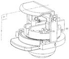
도 2 는 제 1 실시형태에 따른 장치, 특히 개방 위치에 있는 공급 유닛과 탈착된 위치에 있는 카트리지 홀더의 사시도이다. Figure 2 is a perspective view of a device according to the first embodiment, in particular a supply unit in the open position and a cartridge holder in the detached position.
도 3 은 도 2 와 유사한 사시도로서, 삽입 위치에 있는 카트리지 홀더와 개방 위치에 있는 지지 유닛을 갖는다. Figure 3 is a perspective view similar to that of Figure 2, with a cartridge holder in the insertion position and a support unit in the open position.
도 4 는 도 2 및 도 3 과 유사한 사시도로서, 공급 유닛이 폐쇄 위치, 즉 주입 위치에 있다. Fig. 4 is a perspective view similar to Figs. 2 and 3, in which the supply unit is in the closed position, i.e. the injection position.
도 5 는 개방 위치에서 도 4 로부터 평면 (P) 를 따르는 횡단면도이다. Figure 5 is a cross-sectional view along plane P from Figure 4 in an open position.
도 6 은 주입 위치에서 P를 따르는 다른 횡단면도이다. Figure 6 is another cross-sectional view along P at the injection position.
도 7 은 카트리지의 주입 표면의 개략도이다.7 is a schematic view of the injection surface of the cartridge.
도 8 은 제 2 실시형태에 따른 장치, 특히 개방 위치에 있는 지지 유닛과 탈착된 위치에 있는 카트리지 홀더의 사시도이다. Figure 8 is a perspective view of a device according to the second embodiment, in particular a support unit in the open position and a cartridge holder in the detached position.
도 9 는 카트리지 홀더에 대한 주입 수단의 겹합 전에 삽입 위치에 있는 카트리지 홀더를 갖는, 도 8 과 유사한 사시도이다.Fig. 9 is a perspective view similar to Fig. 8, with a cartridge holder in the insertion position prior to lamination of injection means for the cartridge holder.
도 10 은 공급 유닛이 폐쇄 위치에 있는, 도 8 의 길이방향 중간 축선에 따른 단면도이다. Figure 10 is a sectional view along the longitudinal median axis of Figure 8, with the feed unit in the closed position;
도 1 은, 장치 또는 기구 (1) 및 그 장치에 적합한 카트리지 (3) 를 포함하며, 카트리지로부터 제조된 액체를 분배하기 위한 시스템을 단순화된 형태로 보여준다. 액체는 커피, 카푸치노 또는 차와 같은 뜨거운 음료 또는 차가운 음료, 또는 소스, 스프 등과 같은 다른 식품 요리일 수 있다.1 shows a system for distributing a liquid made from a cartridge in simplified form, comprising a device or mechanism 1 and a
각각의 카트리지는 고체, 액체, 겔 또는 페이스트 형태의 1 이상의 식품 성분을 포함한다. 예컨대, 볶아서 분쇄한 커피 분말, 인스턴트 커피, 우유 분말 또는 액체 농축물, 코코아, 또는 잎이나 인스턴트 형태의 차를 포함할 수 있다.Each cartridge contains one or more food ingredients in the form of a solid, liquid, gel or paste. For example, roasted and ground coffee powder, instant coffee, milk powder or liquid concentrate, cocoa, or tea or instant tea may be included.
카트리지는 EP 1472156B1 에 기재된 유형인 것이 바람직한다. 특히, 카트리지 (3) 는 가요성 막 형태의 주입 벽 (10) 및 준비된 액체를 직접 컵에 안내하기 위한 덕트 (44) 을 포함할 수 있고, 상기 주입 벽을 통해 유체 (즉, 다량의 뜨거운 또는 차가운 물) 가 공급 유닛으로부터 주입된다. 상기 막은 카트리지 본체의 밀봉 엣지에 부착될 수 있다. 카트리지는 성분을 담는 기밀성 내부 챔버를 포함할 수 있다. 챔버는, 제조된 액체가 밖으로 나올 수 있도록 하기 위해, 챔버 내로 주입되는 유체의 압력의 상승의 영향 하에서 천공될 수 있다. 챔버의 적어도 하나의 내부 막과 협력하여 카트리지에 대해 특정적인 천공 수단에 의해 액체를 전달하는 천공을 행할 수 있다. 막 재료의 파열 장력 (rupture tension) 에 도달할 때까지, 내부 막을 천공 수단에 대고 변형시킴으로써 천공을 행할 수 있다. 카트리지는 또한, 카트리지 내의 액체의 압력의 상승 중에 외부 멤버레인을 파열하여, 즉 어떠한 내부 천공 요소도 없이 개방될 수도 있다. 카트리지의 이점 중 하나는, 성분의 유동을 감속시키고 성분과 가압 유체 사이의 상호작용을 향상시킴으로써, 추출, 용해 또는 퍼컬레이션 (percolation) 을 카트리지 내부의 4 ~ 20 bar 의 제어된 압력 하에서 행할 수 있다는 것이다. 이러한 원리에 의해, 저압 퍼컬레이션 방법으로 얻을 수 있는 것보다 더 많은 거품 (froth) 을 만들 수 있다. 다른 이점은, 이와 동시에, 유럽특허 1472156 B1 에 기재된 것처럼 액체와 장치 사이의 접촉을 제한할 수 있다는 것이다. 물론, 본 발명은 그 특허에 따른 카트리지의 사용에 국한되지 않는다. 예컨대, 막 및 개방 수단은 필터 요소, 예컨대 종이 및/또는 플라스틱 필터, 및 액체 수집 채널 및/또는 액체 분배용 개구를 포함하는 필터 지지부에 의해 대체될 수 있다.The cartridge is preferably of the type described in EP 1472156B1. In particular, the
본 발명에 따른 장치는 음료를 제조하기 위한 저압 시스템을 위한 포드 (pod) 형태의 카트리지를 포함하여 어떠한 유형의 카트리지와도 관련하여 사용될 수 있다는 것이 이해된다. It is understood that the apparatus according to the present invention may be used in connection with any type of cartridge, including a cartridge in the form of a pod for a low pressure system for producing beverages.
본 명세서에서, 용어 "주입 유체"는 주로 본질적으로 뜨거운 또는 차가운 물, 또는 물과 공기의 혼합물에 관한 것이다.As used herein, the term "infusion fluid" refers primarily to essentially hot or cold water, or a mixture of water and air.
본 장치는, 가압 유체 공급 유닛 (2) 이 내부에 장착되는 지지 구조체 (40) 를 포함할 수 있으며, 그 가압 유체 공급 유닛은 그 장치로부터 탈착될 수 있는 카트리지 홀더 (6) 를 포함한다. 카트리지 홀더 아래에는, 서빙 (serving) 영역 (41) 이 배치되어 있으며, 그 서빙 영역은 예컨대 컵 지지부 (42) 를 포함할 수 있다. 본 장치는, 필요에 따라 유체 공급 유닛 (2) 에 뜨거운 물 및/또는 차가운 물을 공급하기 위한 펌프, 물 히터 및 유체 회로와 연관되는 제거가능한 저장소와 같은 물 저장소를 추가로 포함한다. 본 장치는 또한 적절히 정교한 제어 수단을 포함하는데, 이 제어 수단으로 인해, 사용자는, 미리 결정된 범위의 선택 중에서, 뜨거운 및/또는 차가운 제조 및/또는 분배될 음료의 여러 크기에 대한 몇몇 선택사항을 고를 수 있다. 제어 수단은, 펌프, 물 히터, 및 유체 회로와 연관된 밸브(들)의 스위치를 켜는 것을 선택적으로 제어하는 제어기와 연관될 수 있다. 제어 수단은 레버, 밸브 또는 1 이상의 제어 버튼을 갖는 유형일 수 있다.The apparatus can include a
도 2 내지 도 7 은 본 발명에 따른 장치의 제 1 실시형태를 보여준다. 카트리지 홀더 (6) 및 가압 유체 공급 유닛 (2) 은, 카트리지 홀더 (6) 가 바람직한 방향 (A) 으로 그 유닛에 삽입될 수 있도록 하는 상보적 삽입 수단 (7) 을 포함한다. 상보적 삽입 수단 (7) 은 카트리지 홀더가 본 장치로부터 탈착될 수 있도록 구성되어 있다. 용어 "탈착가능한"은, 카트리지 홀더가 "탈착" 위치에 있을 때 어떠한 영구적인 연결 수단에 의해 본 장치, 특히 공급 유닛 (7) 에 연결되지 않고, 자유롭게 운반될 수 있으므로, 일단 카트리지가 사용되고 나면, 카트리지를 제거하여, 새로운 카트리지 (10) 를 다시 설치할 수 있다는 것을 의미한다. 따라서, 카트리지 홀더의 표면으로부터 음식 잔류물을 제거하기 위해 그 카트리지 홀더를 용이하게 행구거나 세척할 수 있다.Figures 2 to 7 show a first embodiment of the device according to the invention. The
그러나, 본 발명은 본 장치로부터 또는 공급 유닛으로부터 탈착될 수 없지만 드로어 (drawer) 개방 위치로부터 공급 유닛 내에 삽입될 수 있는 카트리지 홀더에도 또한 관련될 수 있다. "드로어 개방" 구성은, 카트리지 홀더를 완전히 제거할 필요없이 카트리지를 설치할 수 있도록 해주는 정지 수단에 의해 카트리지 홀더의 이동이 정지되는 것을 의미한다. 따라서 카트리지 홀더는 드로어 개방 위치에 있을 수 있으며 또한 필요에 따라 (예컨대 세척을 위해) 탈착될 수 있도록 될 수 있다.However, the present invention may also relate to a cartridge holder that can not be removed from the present apparatus or from the supply unit but can be inserted into the supply unit from a drawer open position. The "drawer opening" configuration means that the movement of the cartridge holder is stopped by stop means which allows the cartridge to be installed without the need to completely remove the cartridge holder. Thus, the cartridge holder can be in the drawer open position and can also be detachable (e.g., for cleaning) as needed.
카트리지 홀더를 공급 유닛에 삽입하기 위한 상보적 삽입 수단 (7) 은 다양한 형태를 취할 수 있다. 상보적 수단은, 사용자가 간단하게 카트리지 홀더를 삽입 방향 (A) 으로 밀어서 공급 유닛에 카트리지 홀더를 직접 그리고 실질적으로 선형적으로 삽입할 수 있도록 구성되는 것이 바람직하다. 카트리지 홀더는, 이동 전에 공급 유닛 내 기준 위치에 위치되고, 카트리지와 주입 수단이 연결되어 있다.The complementary inserting means 7 for inserting the cartridge holder into the supply unit can take various forms. The complementary means is preferably configured so that the user can simply and directly push the cartridge holder in the insertion direction A to directly and substantially linearly insert the cartridge holder into the supply unit. The cartridge holder is positioned at a reference position in the supply unit before movement, and the cartridge and the injection means are connected.
가능한 일 실시형태에 따르면, 삽입 수단은 상보적으로 형성된 안내 리브 (18) 및 안내 홈 (19) 을 포함하고, 이들은 각각 카트리지 홀더 (6) 의 측면 및 공급 유닛의 베이스부 (20) 의 내측면에 형성되어 있다. 본 발명의 원리에 따라서, 상기 삽입 수단 (7) 은 측방향에서, 바람직하게는 수평면 (H) 에 대해 조금 경사진 방향으로 이어져 있다. 따라서, 그 카트리지 홀더는 하방으로 조금 경사져서 공급 유닛 내로 삽입된다.According to one possible embodiment, the inserting means comprises complementary formed
유체 공급 유닛 (2) 과 동일한 측에서, 베이스부 (20) 가 움직일 수 없게 본 장치에 고정된다. 이 베이스부 (20) 에는, 베이스부에 대해 이동할 수 있는 디스크 형태의 주입 지지부 (4) 가 설치된다. 이 실시형태에 따른 이하의 설명에서 "가동 지지부"라고 하는 주입 지지부는, 클램핑 수단의 일부를 형성하는 작동 수단 (22) 의 작용 하에서 베이스부를 따라 그리고 회전 및 축선방향 변위의 조합 운동으로 움직일 수 있으며, 이리하여 카트리지 홀더와 카트리지에 대해 지지부를 쉽게 적용시킬 수 있고, 또한 공차 및 기능적 놀음에 대해 보상할 수 있다. On the same side as the
가동 지지부 (4) 는, 바람직하게는 가동 지지부의 중심 축선 (Ⅰ) 으로부터 벗어나 위치된 주입 수단 (5) 을 포함한다 (도 5). 그리고, 가동 지지부의 중심 축선 (Ⅰ) 은, 지지부 (4) 를 낮추어 주입 수단을 결합시킨 후, 카트리지의 주 입 표면의 중심 (0) 에 정렬된다 (도 6). The movable support portion 4 preferably includes injection means 5 located away from the central axis I of the movable support portion (Fig. 5). Then, the center axis I of the movable support is aligned with the center 0 of the injection surface of the cartridge after the support 4 is lowered to engage the injection means (Fig. 6).
가동 지지부 (4) 는 그 지지부의 전방측에 위치한 피봇 핀 (23) 주위에서 베이스부 (20) 에 설치되고, 상기 피봇 핀을 가동 지지부가 카트리지 홀더에 대해 축선방향 운동과 회전 운동의 조합 운동으로 움직일 수 있도록 축선방향으로 안내된다. 도 5 에 도시된 바와 같이, 가동 지지부는 지지부 (4) 의 횡방향 면에 평행한 핀을 포함하며, 이 핀은 베이스부의 1 이상의 축선방향 안내 하우징 또는 슬롯 (24) 에 설치되어 있어, 지지부가 회전 방향과 축선 병진 방향으로 동시에 운동할 수 있다. 그 이점은, 재개방시 가동 지지부에 대한 카트리지의 엣지 (34) 를 분리하는 동안 순수한 선형의 축선방향 운동에 비해 마모를 회피하는 동시에, 기능적 놀음을 보상할 수 있는 구성에 주로 연관되어 있다. The movable support portion 4 is installed on the
개방 위치, 즉 카트리지 홀더로부터 떨어져 있는 위치로부터 주입 위치로의 가동 지지부의 작동은 작동 시스템 (22) 에 의해 행해진다. 다양한 작동 시스템을 상정할 수 있다. 도시된 실시형태에 따르면, 작동 수단은 수동 레버 (30) 에 연결된 토글 (toggle) 레버 (29) 이다. 자동화된 실시형태에서, 레버는 모터로 대체될 수 있다. 바람직하게는, 작동 시스템이 가동 지지부 위에 수직방향으로 위치되고 베이스부에 부착된다. 더욱 구체적으로는, 상기 레버 (30) 는 측방향으로 떨어져 있는 2 개의 아암 (86, 87) 을 포함하는데, 이 아암은, 한편으로, 측방향으로 떨어져 있는 2 개의 고정 핀 (44) 에 의해 고정 베이스부의 2 개의 분지부 (24, 25) 의 단부에, 그리고 다른 한편으로는, 2 개의 다른 가동 핀 (46) 에 의해 토글 레버의 한 쌍의 아암 (31) 에 관절식으로 연결되어 있다. Operation of the movable support from the open position, i. E. A position remote from the cartridge holder, to the injection position is effected by the
작동 시스템 (22) 은 스프링 백 (spring-back) 수단 (도시 안 됨) 에 연결되는 것이 바람직하다. 스프링 백 수단은, 카트리지의 잡힌 엣지 (trapped edge) 에 의해 작동 수단에 반력이 가해지지 않을 때, 자동으로 주입 지지부를 상승 위치 또는 카트리지 홀더로부터 떨어져 있는 위치로 재위치시켜 작동 및 잠금 수단을 이용하여 지지부를 고정시킬 수 있도록 레버 및/또는 토글 레버에 연결될 수 있다. 잠금 수단은 또한 고정된 베이스부와 가동 지지부 (4) 사이에 위치될 수 있다. 스프링 백 수단의 일 예로, 스프링이 카트리지 홀더의 부재시 또는 카트리지 홀더가 도 3 의 위치에 카트리지 없이 삽입되는 때 카트리지 홀더에 카트리지의 부재시, 도 3 에 따른 올려진 위치로 레버를 자동으로 복귀시키기 위해 제공된다. The
도 5 는, 유체 공급 유닛의 세부를 보여주며, 가동 주입 지지부 (4) 가 상승 위치에 있고 공급 유닛에 카트리지 홀더가 배치되어 있는 것을 보여준다.Fig. 5 shows the details of the fluid supply unit, showing that the movable injection support 4 is in the raised position and the cartridge holder is arranged in the supply unit.
본 발명의 바람직한 일 실시형태에 따르면, 주입 수단 (5) 은 카트리지 내로 침입한다. 즉, 주입 수단은 카트리지의 주입 표면을 관통하고, 카트리지 내부로 적어도 부분적으로 들어간다. 주입 수단은, 예컨대, 가동 지지부 (4) 에 고정된 주입 스파이크 (13) 를 포함할 수 있으며, 그 주입 스파이크는 카트리지의 윗면을 천공하거나 자른다. 처음에 카트리지의 주입 표면 (10) 은 조금 볼록할 수 있다. 스파이크는 그를 관통해서 형성되어, 카트리지 내로 주입 유체 (온수 또는 냉수) 를 운송하기 위한 덕트 (14) 를 갖는다. 주입 스파이크는 지지부를 통과하고 카트리지의 반대측에서는 1 이상의 커넥터 (49) 를 통해 연장되어 있다. 뜨거운 유체의 공급 및 주위 온도 또는 차가운 온도의 유체의 공급을 가능하게 하는 2 개의 개별적인 입구 (55, 56) 가 커넥터의 분지부에 제공될 수 있다. 이 입구는 가요성 공급 튜브에 연결되고, 이들 튜브는 유체 시스템의 잔부에 연결된다 (도시되지 않음). 주입 수단에 공급되는 뜨거운 유체 또는 차가운 유체는 1 이상의 밸브 (도시 안 됨) 를 이용하여 선택될 수 있다. 도 5 에 나타낸 바와 같이, 주입 스파이크의 끝에는 작은 단면의 출구 오리피스 (바람직하게는 0.5 ㎜ 미만) 가 있어, 유체의 분류 (jet) 가 고속으로 카트리지 내로 향할 수 있다. 바람직하게는, 카트리지 내에 삽입되는 경우, 상기 오리피스는 덕트 (14) 에 대해 축선방향으로 그리고 카트리지의 바닥쪽으로 향한다 (도 6). 분류의 오프셋 위치, 방향과 높은 속도는 카트리지 내 유체의 난류 생성에 기여하고, 따라서 주입 유체가 심지어 차가운 물인 경우에도 특정 성분의 용해 또는 분산을 향상시키는 것을 목적으로 한다.According to a preferred embodiment of the invention, the injection means (5) enter into the cartridge. That is, the injection means penetrates the injection surface of the cartridge and enters at least partly into the cartridge. The injection means may comprise, for example, an
본 발명의 일 가능성에 따라서, 주입 수단은 탄성 재료로 이루어진 코팅 형태의 밀봉 수단 (16) 을 포함하며, 그 밀봉 수단은 주입 지지부 (4) 의 전체면에 걸쳐 존재한다.According to a possibility of the invention, the injection means comprises a sealing means 16 in the form of a coating made of an elastic material, the sealing means being present over the entire surface of the injection support 4.
주입 수단은 주입 스파이크의 베이스부를 국부적으로 둘러싸는 융기된 환형부 (17) 를 포함한다. 이 환형부 덕분에, 주입 수단의 결합시 스파이크 주위의 위치에서 카트리지의 주입 표면의 국부 압력을 증가시켜 스파이크 주위의 국부적인 밀봉을 향상시키는 것이 가능하다. The injection means includes a raised
밀봉 수단은 탄성 중합 재료, 실리콘, 또는 낮은 경도를 가지며 탄성적으로 가요성인 플라스틱으로 이루어진 코팅일 수 있다. The sealing means may be an elastomeric material, silicone, or a coating of low hardness and elastically flexible plastic.
카트리지의 주입 표면은 또한 가요성일 수 있음을 이해해야 한다. 이 표면은 카트리지에 담긴 기체의 존재로 인해 처음에는 약간 볼록하며, 그 후 밀봉 수단 (16) 에 의해 가해지는 축선방향의 기계적 압력의 영향을 부분적으로 받아 변형될 수 있다. 놀음에 대한 보상에 의한 밀봉은 밀봉 수단 (16) 및 카트리지의 주입 표면의 변형의 조합에 의해 달성된다. 주입 표면의 변형은 카트리지가 주입 유체에 의해 가압될 때 이루어진다. 그러면, 카트리지 내에 내부 추력이 생성되어, 밀봉 수단을 향하게 되고, 카트리지의 표면 (10) 이 상기 수단에 가압된다. 따라서, 카트리지의 전체 주입 표면은 밀봉 코팅의 표면에 대해 누설방지 방식으로 가압된다. 따라서, 이는 심지어 손상된 카트리지, 즉 우연히 천공된 주입 표면을 갖는 카트리지도 장치에서 기능할 수 있는 장점을 갖는다. It should be appreciated that the injection surface of the cartridge may also be flexible. This surface is initially slightly convex due to the presence of the gas contained in the cartridge and can then be partially deformed under the influence of the axial mechanical pressure exerted by the sealing means 16. The sealing by compensation for the play is achieved by a combination of the sealing means 16 and deformation of the injection surface of the cartridge. Deformation of the injection surface occurs when the cartridge is pressurized by the injection fluid. An internal thrust is then created in the cartridge, facing the sealing means, and the
코팅 (16) 은, 스파이크 주위에만 위치되며 탄성재료로 이루어진 링과 같은 개별적인 요소에 의해 대체될 수 있다. The
지지부의 탄성 표면에 의해 제공되는 밀봉 덕분에, 주입 스파이크를 통해 주입되는 가압된 유체는 스파이크에 형성된 오리피스의 베이스부에 직접 또는 그 근방에 유지되고, 따라서 카트리지의 표면 (10) 과 가동 지지부 (4) 의 표면 사이에 다시 나타나지 않는다. 이는 액체와 접촉하는 장치의 표면적을 감소시켜, 액체가 다시 위로 올라갈 가능성을 방지한다. 그러므로, 시스템은 카트리지 홀더에 대해 내누설성이 있으며, 장치 내 카트리지 홀더의 실제 클램핑에 무관하게 그러한 내누설성을 갖게 된다. By virtue of the sealing provided by the resilient surface of the support, the pressurized fluid injected through the injection spike is held directly or in the vicinity of the base portion of the orifice formed in the spike, and thus the
이미 언급한 일 특징에 따르면, 가동 주입 지지부 (4) 및 주입 수단은, 카트 리지 홀더가 카트리지를 포함하고 카트리지 홀더가 유체 공급 유닛에 삽입되는 때에, 클램핑 수단, 특히 작동 시스템 (22) 에 의해 클램핑 부분 (60) 에서 주입 위치에 고정될 수 있다. 가동 지지부 (4) 는 카트리지의 엣징 (edging) (34) 상에 지지되는 클램핑 표면부 (60) 를 포함한다. 엣지 (34) 자체는 카트리지 홀더의 베어링 또는 클램핑 엣지 (40) 에 놓여 있다. 그러므로, 엣징은 클램핑 부분 (60) 과 카트리지 홀더의 엣지 (40) 사이에서 잡힌다. 그러므로, 작동 수단, 특히 레버에 의해 작동되는 토글 레버는 압축 클램핑력을 가하고, 이 클램핑력은 가동 지지부 (4) 에 의해 카트리지의 엣징에 전달된다. 토글 레버를 "강성인 (stiff)" 지점을 통해 이동시킴으로써 얻어지는 토글 레버의 고정은 카트리지가 카트리지 홀더 내에 존재하는 때에만 이루어지고, 따라서 토글 레버를 "강성인" 지점을 통과하게 하여 안정적인 지지부 클램핑 위치를 획득하는데 필요한 과 두께가 생성된다. 이러한 클램핑은, 가압 유체가 카트리지 내로 도입되는 작업 모드에서 카트리지 홀더의 고정에서의 안전을 보장하는 것을 가능하게 하는데 중요하다. 또한, 클램핑은 카트리지의 본체의 엣징으로부터 막 (10) 이 박리될 위험 없이, 카트리지를 밀봉하기 위해 엣징 (34) 을 견고하게 유지하는데 기여한다.According to one feature already mentioned, the movable injection support 4 and the injection means are arranged such that when the cartridge holder comprises a cartridge and the cartridge holder is inserted into the fluid supply unit, the clamping means, in particular by the
카트리지 또는 카트리지 홀더가 존재하지 않으면, 토글 레버에 작용하는 레버에 의해 가동 지지부 (4) 가 하강해도, 지탱 효과가 발생하지 않고, 따라서 토글 레버에 충분한 반력이 생성되지 않는다. 레버 및/또는 토글 레버와 연관된 스프링 백 수단이 존재하기 때문에, 레버는 재개방 방향으로 선회하고, 따라서 사용자가 더 이상 레버를 누르지 않는 경우, 토글 레버가 다시 위로 올라가게 된다. 그러므로, 카트리지 홀더가 제거된 경우 또는 카트리지가 카트리지 홀더에 결합되지 않은 경우, 가동 지지부를 안정적인 하강 위치로 유지할 수 없다. 그러므로, 카트리지 홀더가 개방 위치로 복귀되고, 따라서 카트리지 홀더를 꺼내거나 카트리지 홀더를 그 카트리지와 함께 장치에 삽입할 수 있다.If there is no cartridge or cartridge holder, even if the movable supporting portion 4 is lowered by the lever acting on the toggle lever, no supporting effect occurs, and therefore a sufficient reaction force is not generated in the toggle lever. Since there is a springback means associated with the lever and / or the toggle lever, the lever pivots in the re-opening direction, and thus the toggle lever is raised again when the user no longer presses the lever. Therefore, when the cartridge holder is removed or when the cartridge is not coupled to the cartridge holder, the movable support can not be held in the stable lowered position. Therefore, the cartridge holder is returned to the open position, and therefore, the cartridge holder can be taken out or the cartridge holder can be inserted into the apparatus together with the cartridge.
공급 유닛 내의 카트리지 홀더에 가해지는 클램핑력은 밀봉 수단이 주로 받는 것은 아니다. 이는, 밀봉 기능이 공급 유닛 내의 카트리지 홀더를 클램핑하는 기능과는 부분적으로 분리되어 있어 유리하고, 클램핑 기능은 본 장치가 압력을 받고 있는 동안 카트리지 홀더가 풀리는 가능성을 방지하려는 것이다. 이로써, 특히 카트리지의 주입 표면이 가요성 막인 경우, 그 주입 표면이 파열될 위험없이, 주입 지점에 가능한 한 가까이에서 카트리지의 가요성 부분을 밀봉할 수 있게 된다. 그래서, 밀봉 수단은 압축 스트레스를 덜 받게 되고, 따라서 그의 탄성과 밀봉성을 더 오랫 동안 유지하게 된다.The clamping force applied to the cartridge holder in the supply unit is not mainly received by the sealing means. This is advantageous because the sealing function is partially separated from the function of clamping the cartridge holder in the supply unit and the clamping function is to prevent the possibility of the cartridge holder being loosened while the apparatus is under pressure. This makes it possible to seal the flexible portion of the cartridge as close as possible to the injection point, especially if the injection surface of the cartridge is a flexible film, without risk of rupturing the injection surface. Thus, the sealing means is less subject to compressive stress, and therefore maintains its elasticity and sealability for a longer period of time.
물론, 가동 지지부의 작동 및 잠금 수단은 토글 레버 외의 구성일 수 있다. 이는 예컨대, 캠 또는 일련의 기어일 수 있다. Of course, the actuation and locking means of the movable support may be of a configuration other than the toggle lever. This may be, for example, a cam or a series of gears.
가동 지지부의 두께는 조정 수단에 의해 조정될 수 있다. 시스템을 구성하는 다양한 부품, 즉 카트리지와 장치 자체에서의 마모, 공차, 열로 인해 가능한 팽창의 현상을 고려하여, 작동 수단이 올바르게 작동하는 것을 보장하기 위해, 조정이 필요할 수 있다. 조정을 통해, 예컨대 "강성인" 지점을 통한 토글 레버의 전환에 필요한 전환력을 조정하는 것이 가능하다. 조정 수단은 작동 수단을 폐쇄시키는 힘을 조정할 수 있고, 따라서 카트리지 내 고압 조건 하에서 양호한 밀봉 을 보장하기 위해 주입 수단에 의해 카트리지의 표면에 가해지는 힘에 영향을 미친다. The thickness of the movable support portion can be adjusted by the adjustment means. Adjustments may be necessary to ensure that the actuating means operates correctly, taking into account the phenomena of possible expansion due to wear, tolerance, heat in the various components that make up the system, namely the cartridge and the device itself. Through adjustment, it is possible to adjust the switching force necessary for switching the toggle lever through, for example, the "stiffness" The adjusting means can adjust the force to close the actuating means and thus affect the force applied to the surface of the cartridge by the injecting means to ensure good sealing under high pressure conditions in the cartridge.
본 발명의 일 과제는, 주입 수단이 카트리지의 밖으로, 더욱 구체적으로 주입 스파이크의 침입 부분으로부터 제거된 후 카트리지의 주입 표면 밖에서 또한 그와 동일한 쪽에서 액체 분류가 발생될 위험을 감소시키는 것이다. 이러한 현상은 일반적으로, 한편으로는 카트리지가 카트리지 내의 유체의 가압시 소정량의 압축 가스를 포함하기 때문에 발생하며, 그 기체는 주입 수단의 분리시 급속히 팽창한다. An object of the present invention is to reduce the risk of liquid splashing occurring outside the injection surface of the cartridge after the injection means is removed from the cartridge, more specifically from the intrusion portion of the injection spike. This phenomenon generally occurs because, on the one hand, the cartridge contains a certain amount of compressed gas upon pressurization of the fluid in the cartridge, and the gas expands rapidly upon separation of the injection means.
이러한 단점을 극복하기 위해, 본 발명에 따른 장치는, 한편으로는 수평면 (H) 에 대해 조금의 각도로 기울어진 형태로 카트리지 홀더 (6) 를 유지하여, 동일한 수평면에 대해 카트리지의 주입 표면 (10) 을 실질적으로 경사지게 하며, 다른 한편으로는 카트리지의 표면 (10) 또는 카트리지 홀더의 실질적으로 가장 높은 측에 주입 수단 (5) 을 위치시켜 주입 지점의 위치에서 기체 버블을 유지하게 하는 해결책을 제안한다. 도 7 은 주입 표면 (10) 과 주입 지점 (50) 을 나타낸다. 본 발명에 따른 주입 표면의 경사를 결정하기 위해, 그리고 상기 표면의 가능한 볼록함 또는 오목함을 고려하여, 카트리지의 엣지 (34) 로부터 시작하는 평평한 투영 표면 (S) 이 종래와 같이 주입 표면의 기준 표면으로서 종래와 같이 취해진다. 정의에 의해 "주입 표면"으로서 고려되는 이 표면 (S) 은 도 5 에 도시된 바와 같이 수평면 (H) 에 대해 각 (A) 을 형성한다. 그 표면은, 카트리지가 카트리지 홀더에 위치되며, 카트리지 홀더는 베이스부에 정확하게 삽입되는 경우, 4 개의 가상 4분면 (51, 52, 53, 54) 으로 이루어진다. 바람직하게는 주입 지점은 수평면에 대해 가장 높이 위치된 4분면 (51) 내측에 위치된다. 더 바람직하게는 주입 수단은, 주입 지점이 수평면에 대해 가장 경사진 우측 부분 (D; 중심을 통과함) 측에 정렬하여 위치되도록 배치된다. 바람직하게는 '표면 (S)'의 경사각은 2 ~ 25 도, 더 바람직하게는 약 5 ~ 20 도이다. To overcome this disadvantage, the device according to the present invention maintains the
추가적인 일 해결책은 또한, 주입 전에 카트리지의 내부 공간을 감소시키는 것과, 카트리지로부터 주입 수단의 제거시 챔버의 공간을 재설정하는 것에 있다. 카트리지 공간의 이러한 변화로 인해, 카트리지 내 높아진 압력을 적어도 부분적으로 보상하기에 충분한 흡수 공간을 형성할 수 있다. 기체 팽창은, 카트리지의 외측에 액체의 분류를 분사시켜 더 이상 갑자기 발생하지 않지만, 기체는 주입 수단의 제거 후 카트리지의 가변적인 공간에서 적어도 부분적으로 팽창하려는 경향이 있다. An additional workaround is also to reduce the internal space of the cartridge prior to injection and to reset the chamber's space upon removal of the injection means from the cartridge. Due to this change in cartridge space, it is possible to create an absorption space sufficient to at least partially compensate for the increased pressure in the cartridge. The gas expansion does not occur any more suddenly by jetting the liquid fraction to the outside of the cartridge, but the gas tends to expand at least partially in the variable space of the cartridge after removal of the injection means.
그것을 행하기 위해, 카트리지의 벽 (10) 을 카트리지의 내측을 향해 밀어서 카트리지의 내부 공간을 감소시키도록 구성된 가동 지지부의 융기 결합 부분 (15) 이 제공된다. 결합 표면은 가동 지지부의 하부 벽 (16) 의 일부를 형성한다. 카트리지의 주입 표면이 충분히 가요성이므로 (예컨대, 두께가 십분의 수 ㎜ 인 막이므로), 이 표면은, 가동 지지부가 주입 위치로 위치되는 때 가동 지지부의 결합 표면과 접촉하여 변형된다. 도 6 에 도시된 바와 같이, 카트리지 홀더에 대한 주입 유닛의 폐쇄시, 융기 결합 부분 (15) 은 카트리지 막을 안쪽으로 밀어 오목하게 만든다. 결합 부분 (15) 은, 이미 상기된 바와 같이 카트리지의 표면에 서 밀봉 요소로서 작용하는 탄성재로 이루어질 수 있다. In order to do so, a raised engagement portion (15) of a movable support configured to push the wall (10) of the cartridge toward the inside of the cartridge to reduce the internal space of the cartridge is provided. The engaging surface forms a part of the lower wall (16) of the movable support. This surface is deformed in contact with the mating surface of the movable support when the movable support is positioned at the injection position, since the injection surface of the cartridge is sufficiently flexible (e.g., a film having a thickness of several tenths of a millimeter). As shown in Fig. 6, at the time of closing the injection unit with respect to the cartridge holder, the raised
가동 지지부 (4) 가 카트리지 홀더로부터 분리되는 경우, 결합 부분 (15) 은 카트리지에 더 이상 압력을 가하지 않고, 주입 표면은 카트리지 내 기체의 팽창의 영향으로 적어도 부분적으로 본래 위치로 복귀하려는 경향이 있다.When the movable support 4 is detached from the cartridge holder, the engaging
가능한 제 2 실시형태가 도 8 ~ 도 10 에 도시되어 있다. 이 경우, 카트리지 홀더 (60) 및 공급 유닛의 베이스부 (200) 에는 쐐기형 상보적 삽입 수단 (750) 이 장착된다. 카트리지 홀더는 단지 미끄러짐으로써 공급 유닛의 엣지를 따라 삽입되도록 구성되어 있다. 카트리지 홀더는 카트리지 홀더의 삽입 및 제거시 조작의 편의를 위해 핸들 (682) 을 갖는다. 이러한 수단의 원리는, 카트리지 홀더가 슬라이딩하여 상보적 삽입 수단의 기하학적 형상과 카트리지에서 가해지는 유체 압력의 조합된 효과로 그 삽입 위치에서 베이스부에 충분이 걸림으로써 삽입이 가능하다는 것이다. 시스템이 가압되자마자, 카트리지와 공급 유닛의 마찰력이 증가하여, 클램핑이 공급 유닛의 내면과 카트리지 홀더 사이에서 이루어진다.A possible second embodiment is shown in Figures 8-10. In this case, the wedge-shaped complementary inserting
이전의 실시형태에서와 같이, 본 장치는, 도 1 에서 처럼 본 장치의 잔부에 고정되어 있는 유체 공급 유닛 (2) 으로부터 탈착가능한 카트리지 홀더 (60) 를 포함한다. 카트리지 홀더는 자유 지지 부분 (110) 을 갖는데, 이 자유 지지 부분은 상부쪽으로 넓게 개방되어 있으며 카트리지 (3) 를 수용하기 위한 쉘을 형성한다. 따라서, 카트리지는 자유 부분 또는 쉘에 의해 형성되는 공동에 놓이게 되고, 카트리지의 엣지 (340) 는 카트리지 홀더의 상측 엣지 (712) 에 접혀놓이게 된 다.As in the previous embodiment, the apparatus includes a
카트리지 홀더 (60) 는 가변적인 두께의 리브 (710) 를 형성하는 2 개의 측방 엣지를 포함한다. 더욱 구체적으로, 엣지 또는 릿지는 카트리지 홀더의 자유 삽입 단부의 방향으로 감소하는 두께를 갖는다. 리브의 하부 릿지 (711) 는 슬로프를 형성하고 유닛으로의 카트리지 홀더의 삽입 방향으로 상부 릿지 (712) 를 향해 수렴된다. 그러므로, 리브는 카트리지 홀더의 자유 단부의 방향으로 점차 감소하는 릿지 (711, 712) 에 의해 규정되는 두께를 갖는다. 카트리지 홀더의 각 측에는, 하부 릿지 (711) 가 베이스부에 형성된 각 홈의 하부 릿지 (713) 에 접해 놓이게 된다. 바람직하게는 베이스부의 릿지 (713) 는 실질적으로 수평이거나 조금 기울어져 있다. 따라서, 카트리지 홀더의 하부 릿지 (711) 는 카트리지 홀더의 상부 베어링 엣지 (712) 에 대해 경사 각 (B) 을 형성하며, 그 베어링 엣지 위에 카트리지의 엣징 (340) 이 접해 놓인다. 이 각 (B) 은 바람직하게는 2 ~ 20 도, 예컨대 약 4 ~ 6 도이다. 이런 식으로, 카트리지 홀더는, 엣지 (712) 의 경사를 유지하면서, 하부 릿지 (711, 713) 를 따르는 리브의 안내에 의해 실질적으로 수평하게 또는 조금 경사진 형태로 베이스부 (200) 내로 삽입된다. 리브의 각으로 인해, 카트리지의 주입 표면 (111) 은, 삽입 및 주입 위치에서의 유지 작동시 경사를 유지한다. The
따라서, 쐐기형 삽입 수단은 여러 기능을 가질 수 있는 것이 명확하게 이해된다. "모스 테이퍼(Morse taper)" 원리를 이용하는 제 1 기능은 놀음 보상 및/또는 주입 압력을 이용하는 "자체 잠금" 클램핑 기능이다. 제 2 기능은 액체 의 재기를 회피하기 위한 카트리지의 주입 지점의 상승에 연관된다. 다른 기능은 또한, 특히 카트리지 홀더의 삽입의 개시시 특히 카트리지의 표면으로부터 가능한 떨어져 주입 스파이크를 유지하여, 공급 유닛의 삽입 수단에 카트리지 홀더의 결합을 촉진하여, 따라서 특히 카트리지의 주입 표면이 조금 볼록한 형상을 갖는 경우 그 주입 표면이 파열되거나 찢어지는 것을 회피하는 것이다. Accordingly, it is clearly understood that the wedge-shaped insertion means can have various functions. The first function utilizing the "Morse taper" principle is a "self locking" clamping function that utilizes knock compensation and / or injection pressure. The second function is associated with the elevation of the injection point of the cartridge to avoid jerks of liquid. Another function is also to maintain the injection spike, particularly at the beginning of the insertion of the cartridge holder, especially at the point of possible separation from the surface of the cartridge, thereby facilitating the engagement of the cartridge holder with the insertion means of the supply unit, It is avoided that the injection surface ruptures or tears.
공급 유닛은 회전방향으로 움직일 수 있는, 주입 수단 (500) 이 배치되어 있는 지지부 (40) 를 자체적으로 갖는다. 더욱 구체적으로, 디스크 형태의 가동 지지부 (40) 는 디스크의 측방, 예컨대 후방에 위치된 회전축 (460) 에서 베이스부의 연장부 (282) 에 설치되어 있다. 가동 지지부는, 도 1 ~ 도 6 의 실시형태에서처럼, 토글 레버식의 작동 수단 (275) 및 레버 (276) 에 의해 작동된다. 주입 수단은 도 1 ~ 도 6 의 실시형태의 것과 동일하다. 폐쇄시, 가동 지지부 (40) 는 카트리지의 표면을 가압하기 위해 공급 유닛의 고정된 베이스부에서 형성된 개구를 통과한다. 가동 지지부는 이미 설명한 것과 동일한 이유로 폐쇄시 카트리지의 공간을 줄이는 것이 가능한 볼록 형상의 결합 부분 (150) 을 포함한다.The supply unit itself has a
공급 유닛의 고정된 베이스부의 내면에 대한 카트리지 (345) 의 엣지의 클램핑은 쐐기형 구성과 카트리지 내의 압력 상승의 조합에 의해 발휘되는 "모스 테이퍼" 효과에 의해 주로 이루어진다.Clamping of the edge of the
물론, 본 발명은 설명한 실시형태로 국한되지 않으며, 첨부된 청구범위에 속하는 다른 가능한 실시형태로 확장된다.Of course, the invention is not limited to the embodiments described, but extends to other possible embodiments falling within the scope of the appended claims.
Claims (27)
Applications Claiming Priority (3)
| Application Number | Priority Date | Filing Date | Title |
|---|---|---|---|
| EP07103613.1 | 2007-03-06 | ||
| EP20070103613 EP1967100B1 (en) | 2007-03-06 | 2007-03-06 | System for preparing a beverage from a capsule and method |
| PCT/EP2008/052339 WO2008107348A1 (en) | 2007-03-06 | 2008-02-27 | System and method for preparing a liquid beverage from a cartridge |
Publications (2)
| Publication Number | Publication Date |
|---|---|
| KR20090122938A KR20090122938A (en) | 2009-12-01 |
| KR101431858B1 true KR101431858B1 (en) | 2014-08-25 |
Family
ID=38267946
Family Applications (1)
| Application Number | Title | Priority Date | Filing Date |
|---|---|---|---|
| KR1020097018608A Active KR101431858B1 (en) | 2007-03-06 | 2008-02-27 | System and method for making liquid beverage from cartridges |
Country Status (25)
| Country | Link |
|---|---|
| US (2) | US8671828B2 (en) |
| EP (1) | EP1967100B1 (en) |
| JP (1) | JP5096501B2 (en) |
| KR (1) | KR101431858B1 (en) |
| CN (1) | CN101626712B (en) |
| AR (1) | AR065609A1 (en) |
| AT (1) | ATE431712T1 (en) |
| AU (1) | AU2008223929B2 (en) |
| BR (1) | BRPI0808423B1 (en) |
| CA (1) | CA2679502C (en) |
| CL (1) | CL2008000658A1 (en) |
| DE (1) | DE602007001147D1 (en) |
| DK (1) | DK1967100T3 (en) |
| ES (1) | ES2324630T3 (en) |
| MX (1) | MX2009009314A (en) |
| MY (1) | MY152505A (en) |
| NZ (1) | NZ579207A (en) |
| PH (1) | PH12013502154B1 (en) |
| PL (1) | PL1967100T3 (en) |
| PT (1) | PT1967100E (en) |
| RU (1) | RU2454912C2 (en) |
| TW (1) | TWI468134B (en) |
| UA (1) | UA94993C2 (en) |
| WO (1) | WO2008107348A1 (en) |
| ZA (1) | ZA200906914B (en) |
Cited By (4)
| Publication number | Priority date | Publication date | Assignee | Title |
|---|---|---|---|---|
| KR20200024251A (en) * | 2017-06-26 | 2020-03-06 | 프리지오 아게 | Devices for Making Beverages |
| US11453548B2 (en) | 2016-07-07 | 2022-09-27 | Freezio Ag | Single-portion package, use, and preparation machine |
| US11479457B2 (en) | 2016-01-12 | 2022-10-25 | Freezio Ag | Dispenser having a cartridge holder |
| US12290199B2 (en) | 2017-11-27 | 2025-05-06 | Freezio Ag | Cartridge receptacle, cartridge system, beverage preparation machine, and method for producing a beverage |
Families Citing this family (89)
| Publication number | Priority date | Publication date | Assignee | Title |
|---|---|---|---|---|
| US9795243B2 (en) * | 2005-05-23 | 2017-10-24 | Adrian Rivera | Single serving brewing material holder |
| US7685931B2 (en) | 2005-05-23 | 2010-03-30 | Adrian Rivera | Systems and methods for forming pre-packaged brewing material |
| US9844292B2 (en) | 2009-10-30 | 2017-12-19 | Adrian Rivera | Coffee maker with multi and single cup modes |
| US8720320B1 (en) | 2007-07-13 | 2014-05-13 | ARM Enterprises, Inc. | Pod adaptor system for single service beverage brewers |
| US8621981B2 (en) * | 2009-10-30 | 2014-01-07 | Adrian Rivera | Coffee maker |
| ATE454073T1 (en) * | 2007-03-06 | 2010-01-15 | Nestec Sa | DEVICE FOR PRODUCING A LIQUID FOOD FROM A CAPSULE |
| US9179797B2 (en) | 2007-07-13 | 2015-11-10 | Adrian Rivera | Disposable single serving beverage pod adapter |
| US9242790B2 (en) | 2007-07-13 | 2016-01-26 | Adrian Rivera | Method for tamping brewing material using a self tamping single serving brewing material holder |
| US10722066B2 (en) | 2010-12-04 | 2020-07-28 | Adrian Rivera | Windowed single serving brewing material holder |
| US12342955B2 (en) | 2020-10-30 | 2025-07-01 | Adrian Rivera Maynez Enterprises, Inc. | Brewing material container for a beverage brewer |
| US10258186B2 (en) | 2013-02-01 | 2019-04-16 | Adrian Rivera | Brewing cartridge |
| US9907425B2 (en) | 2007-07-13 | 2018-03-06 | Adrian Rivera | Reusable brewing cartridge |
| US8967038B2 (en) | 2007-07-13 | 2015-03-03 | Adrian Rivera | Cartridge for use in coffee maker |
| US11337543B2 (en) | 2007-07-13 | 2022-05-24 | Adrian Rivera | Brewing material holder |
| US11832755B2 (en) | 2007-07-13 | 2023-12-05 | Adrian Rivera | Brewing material container for a beverage brewer |
| US10865039B2 (en) | 2010-12-04 | 2020-12-15 | Adrian Rivera | Single serving brewing material holder |
| US12396588B2 (en) | 2007-07-13 | 2025-08-26 | Adrian Rivera Maynez Enterprises, Inc. | Brewing material container for a beverage brewer |
| US9271597B2 (en) * | 2007-07-13 | 2016-03-01 | ARM Enterprises | Single serving reusable brewing material holder |
| US9572452B2 (en) | 2010-12-04 | 2017-02-21 | Adrian Rivera | Single serving brewing material adapter with readable label |
| PT2071986E (en) | 2007-12-18 | 2012-04-13 | Nestec Sa | System for preparing a beverage from ingredients supported by an encoded insert |
| PT2071988E (en) | 2007-12-18 | 2011-06-07 | Nestec Sa | Device for preparing a beverage with removable injection member |
| US8043645B2 (en) | 2008-07-09 | 2011-10-25 | Starbucks Corporation | Method of making beverages with enhanced flavors and aromas |
| IT1391885B1 (en) * | 2008-11-03 | 2012-01-27 | Hausbrandt Trieste 1892 Spa | PERFORATOR DEVICE FOR CAPSULES AND MACHINE FOR THE PREPARATION OF DRINKING DRINKS SUCH A DEVICE. |
| ES2471448T3 (en) * | 2009-03-27 | 2014-06-26 | Kraft Foods R & D, Inc. | Beverage concentrates |
| US11464357B2 (en) | 2009-10-30 | 2022-10-11 | Adrian Rivera | Beverage brewer with multi- and single-cup modes |
| US10251509B2 (en) | 2009-10-30 | 2019-04-09 | Adrian Rivera | Coffee maker with multi and single cup modes |
| US9113747B2 (en) | 2009-10-30 | 2015-08-25 | Adrian Rivera | Single and multi-cup coffee maker |
| IT1397492B1 (en) * | 2009-12-21 | 2013-01-16 | Koninkl Philips Electronics Nv | INFUSION GROUP FOR BEVERAGES WITH A WASHING SYSTEM. |
| IT1400070B1 (en) * | 2010-05-27 | 2013-05-17 | Longhi Appliances S R L Divisione Commerciale Ariete De | INFUSION CHAMBER FOR PRE-PACKAGED CHARGES FOR ESPRESSO COFFEE MACHINES. |
| US10071851B2 (en) | 2010-07-12 | 2018-09-11 | Robert Bao Vu | Apparatus and products for producing beverages, and methods for making and using same |
| EP2460449A1 (en) | 2010-12-06 | 2012-06-06 | Nestec S.A. | A beverage preparation machine with automatic cleaning system |
| FR2968914A1 (en) | 2010-12-17 | 2012-06-22 | Jacques Pitoux | APPARATUS FOR DISPENSING A HOT BEVERAGE FOR A HOUSEHOLD MACHINE FOR INFUSIONING A PULVERULENT PRODUCT, COFFEE IN PARTICULAR, WHICH IS DOSE CONDITIONED |
| US9370272B2 (en) | 2011-01-31 | 2016-06-21 | Nestec S.A. | Beverage production machine comprising features to facilitate capsule loading and unloading |
| PT2675730E (en) | 2011-02-16 | 2015-04-30 | Nestec Sa | Container for the preparation of beverage comprising an improved perforable foil and method for preparing a beverage |
| US9510705B2 (en) * | 2011-04-13 | 2016-12-06 | Patrick J. Rolfes | Pre-packaged beverage brewer press |
| US20120285330A1 (en) * | 2011-05-09 | 2012-11-15 | Eko Brands, Llc | Beverage brewing device |
| US8707855B2 (en) | 2011-05-09 | 2014-04-29 | Eko Brands, Llc | Beverage Brewing Device |
| WO2012177999A2 (en) * | 2011-06-23 | 2012-12-27 | Sunbeam Products, Inc. | Mixed beverage maker |
| EP2599412A1 (en) | 2011-12-01 | 2013-06-05 | Nestec S.A. | A beverage preparation machine |
| KR101326786B1 (en) * | 2011-12-06 | 2013-11-08 | 주식회사 콜러노비타 | capsule extractor for improving adhension property |
| GB2499005B (en) * | 2012-02-02 | 2014-06-25 | Kraft Foods R & D Inc | Improvements in or relating to beverage preparation machines |
| EP2819561B8 (en) * | 2012-02-29 | 2019-08-14 | Société des Produits Nestlé S.A. | Container holder with filtration unit for use in a nutritional preparation machine |
| EP2638833A1 (en) | 2012-03-16 | 2013-09-18 | Nestec S.A. | A beverage preparation machine with cleanable brewing head |
| WO2013160091A1 (en) * | 2012-04-24 | 2013-10-31 | Nestec S.A. | A capsule holder for a beverage preparation machine |
| US9451846B2 (en) | 2012-07-24 | 2016-09-27 | Nestec S.A. | Capsule for use in a food preparation machine |
| SG11201500739WA (en) | 2012-08-24 | 2015-03-30 | Nestec Sa | A capsule for use in a food preparation machine |
| JP2014042666A (en) * | 2012-08-27 | 2014-03-13 | Zojirushi Corp | Beverage extractor |
| EP2892824B1 (en) | 2012-09-05 | 2017-05-10 | Nestec S.A. | A beverage capsule with anti-dripping membrane |
| US11013364B2 (en) | 2013-02-01 | 2021-05-25 | Adrian Rivera | Brewing cartridge adapter |
| US12185866B2 (en) | 2013-02-01 | 2025-01-07 | Adrian Rivera | Brewing cartridge adapter |
| CA2943914C (en) * | 2013-04-03 | 2018-11-06 | 2266170 Ontario Inc. | Capsule machine and components |
| MX2015015972A (en) | 2013-05-28 | 2016-04-13 | Nestec Sa | A capsule for beverage preparation. |
| HUE031937T2 (en) | 2013-06-24 | 2017-08-28 | Nestec Sa | A capsule for preparing edible compositions |
| EP3019421B1 (en) | 2013-07-10 | 2018-09-26 | Nestec S.A. | A capsule for beverage preparation |
| CN103584735B (en) * | 2013-11-20 | 2016-04-06 | 宁波西文电器有限公司 | The extraction module of coffee machine |
| US9307860B2 (en) | 2014-02-14 | 2016-04-12 | Remington Designs, Llc | Processor control of solute extraction system |
| ES2656680T3 (en) | 2014-03-07 | 2018-02-28 | Nestec S.A. | Packaging and beverage machine |
| EP3160310A1 (en) | 2014-06-25 | 2017-05-03 | Nestec S.A. | A food or beverage preparation machine |
| CH709895B1 (en) * | 2014-07-18 | 2018-01-31 | Scacco Sa | Infusion device to make an infused beverage such as coffee, tea, chocolate herbal tea. |
| US10111554B2 (en) | 2015-03-20 | 2018-10-30 | Meltz, LLC | Systems for and methods of controlled liquid food or beverage product creation |
| US9346611B1 (en) | 2015-03-20 | 2016-05-24 | Meltz, LLC | Apparatus and processes for creating a consumable liquid food or beverage product from frozen contents |
| US10314320B2 (en) | 2015-03-20 | 2019-06-11 | Meltz, LLC | Systems for controlled liquid food or beverage product creation |
| US9487348B2 (en) | 2015-03-20 | 2016-11-08 | Meltz, LLC | Systems for and methods of providing support for displaceable frozen contents in beverage and food receptacles |
| US10477883B2 (en) | 2015-08-25 | 2019-11-19 | Cornelius, Inc. | Gas injection assemblies for batch beverages having spargers |
| US10785996B2 (en) | 2015-08-25 | 2020-09-29 | Cornelius, Inc. | Apparatuses, systems, and methods for inline injection of gases into liquids |
| EP3199071B1 (en) | 2016-01-27 | 2019-05-08 | Koninklijke Douwe Egberts B.V. | System for preparing a liquid beverage from a capsule |
| ES2962677T3 (en) | 2016-01-27 | 2024-03-20 | Douwe Egberts Bv | A system for preparing a liquid beverage from a capsule, the capsule configured to be used in a system |
| US20170304784A1 (en) * | 2016-04-26 | 2017-10-26 | Cornelius, Inc. | Gas dissolution assemblies for batch beverages |
| JP7177049B2 (en) | 2016-11-09 | 2022-11-22 | ペプシコ・インク | Carbonated Beverage Maker, Method and System |
| US11643269B2 (en) | 2016-12-01 | 2023-05-09 | Bedford Systems, LLC | Container and opening arrangement for beverage production |
| BR112019010296B1 (en) * | 2016-12-29 | 2023-04-18 | Société Des Produits Nestlé S.A | MACHINE FOR PREPARING COLD DRINKS AND METHOD FOR PREPARING COLD DRINKS |
| CN108567332A (en) * | 2017-03-08 | 2018-09-25 | 何宜佶 | beverage preparation system |
| WO2018200922A1 (en) | 2017-04-27 | 2018-11-01 | Meltz, LLC | Method for centrifugal extraction and apparatus suitable for carrying out this method |
| KR102434273B1 (en) * | 2017-09-01 | 2022-08-22 | 엘지전자 주식회사 | Beverage maker |
| KR102647459B1 (en) | 2017-11-15 | 2024-03-13 | 소시에떼 데 프로듀이 네슬레 소시에떼아노님 | System for manufacturing multi-ingredient beverages from various container types |
| KR102557939B1 (en) * | 2017-11-17 | 2023-07-21 | 엘지전자 주식회사 | Beverage maker and method for operating thereof |
| EP4289317A3 (en) * | 2018-03-22 | 2023-12-20 | Bedford Systems LLC | Puncture mechanism for beverage machine |
| EP3823503B1 (en) * | 2018-07-16 | 2024-04-17 | AZ Design GmbH | Brewing machine for single serve capsules containing brewing material, and method for brewing a brewed beverage |
| US11040314B2 (en) | 2019-01-08 | 2021-06-22 | Marmon Foodservice Technologies, Inc. | Apparatuses, systems, and methods for injecting gasses into beverages |
| US12193598B2 (en) | 2019-04-08 | 2025-01-14 | Adrian Rivera | Beverage brewer with multi- and single-cup modes |
| US11724849B2 (en) | 2019-06-07 | 2023-08-15 | Cometeer, Inc. | Packaging and method for single serve beverage product |
| WO2020039411A2 (en) | 2019-09-28 | 2020-02-27 | Famatek Gmbh | Capsule comprising a main and a supplemental precursor ingredient, method for production of said capsule and method for preparing a beverage |
| USD927250S1 (en) | 2020-03-23 | 2021-08-10 | Eko Brands, Llc | Reusable filter cartridge |
| US11805934B1 (en) | 2020-10-21 | 2023-11-07 | Adrian Rivera | Brewing material lid and container for a beverage brewer |
| US12171361B2 (en) | 2020-12-30 | 2024-12-24 | Sharkninja Operating Llc | Hybrid receptacle beverage brewing system |
| USD1055632S1 (en) | 2021-02-26 | 2024-12-31 | Universal Coffee LLC | Reusable filter cartridge |
| CN113017418A (en) * | 2021-04-23 | 2021-06-25 | 胜斗士(上海)科技技术发展有限公司 | Beverage preparation device and beverage preparation method |
| USD1048792S1 (en) | 2023-04-12 | 2024-10-29 | Sharkninja Operating Llc | Coffee machine |
| USD1048793S1 (en) | 2023-05-02 | 2024-10-29 | Sharkninja Operating Llc | Coffee machine |
Citations (1)
| Publication number | Priority date | Publication date | Assignee | Title |
|---|---|---|---|---|
| KR20060090198A (en) * | 2005-02-07 | 2006-08-10 | 네스텍소시에테아노님 | Apparatus for preparing beverage from capsule by injection of pressurized fluid and its capsule holder |
Family Cites Families (21)
| Publication number | Priority date | Publication date | Assignee | Title |
|---|---|---|---|---|
| BE637168A (en) * | 1962-09-13 | |||
| DE2605957B2 (en) * | 1976-02-14 | 1978-06-01 | Wigo Gottlob Widmann & Soehne Gmbh Und Co Kg, 7220 Villingen-Schwenningen | Electric coffee maker |
| DE2847548C2 (en) | 1978-11-02 | 1983-03-03 | Diehl GmbH & Co, 8500 Nürnberg | Electric projectile fuse |
| US4280401A (en) * | 1979-11-13 | 1981-07-28 | Cleland Robert K | Brew rail adapter |
| DE8705978U1 (en) * | 1987-04-24 | 1988-08-18 | Robert Krups Stiftung & Co KG, 5650 Solingen | Device for preparing hot drinks such as coffee, tea, etc. |
| US4944217A (en) * | 1989-07-13 | 1990-07-31 | Sharky Watanabe | Automatic coffee brewing apparatus |
| NL9002072A (en) * | 1990-09-21 | 1992-04-16 | Sara Lee De Nv | METHOD AND APPARATUS FOR MAKING COFFEE USING A FILTER PAN AND A FILTER CARTRIDGE |
| US6606938B2 (en) * | 2001-04-06 | 2003-08-19 | Keurig, Incorporated | Two step puncturing and venting of single serve filter cartridge in a beverage brewer |
| ITTO20010902A1 (en) * | 2001-09-21 | 2003-03-21 | Sgl Italia Srl | COFFEE MACHINE'. |
| US6786134B2 (en) * | 2002-02-07 | 2004-09-07 | The Coca-Cola Company | Coffee and tea dispenser |
| US6805042B2 (en) * | 2002-05-10 | 2004-10-19 | Unilever Bestfoods, North America, Division Of Conopco, Inc. | Apparatus for brewing a beverage |
| SI1444932T1 (en) * | 2003-02-07 | 2006-04-30 | Nestec Sa | Linear extraction unit for the preparation under pressure of a drink from a cartridge |
| EP1510159A1 (en) * | 2003-08-25 | 2005-03-02 | Nestec S.A. | Procedure for making a food product |
| US7237475B2 (en) * | 2003-12-23 | 2007-07-03 | Electrical And Electronics, Limited | Cabinet design of filter holder for pressurized espresso machines |
| ATE390874T1 (en) * | 2003-12-23 | 2008-04-15 | Electrical & Electronics Ltd | FILTER HOLDER DRAWER FOR ESPRESSO COFFEE MACHINES |
| US6904840B1 (en) * | 2004-01-28 | 2005-06-14 | Grindmaster Corporation | Brewer apparatus with improved tray assembly |
| NL1026834C2 (en) * | 2004-08-12 | 2006-02-14 | Sara Lee De Nv | Prepare tea using a tea pad and coffee maker. |
| US7337704B2 (en) * | 2005-05-25 | 2008-03-04 | Sunbeam Products, Inc. | Single serve beverage maker with coordinated heating and pumping periods |
| US7578584B2 (en) * | 2005-09-29 | 2009-08-25 | Brother Kogyo Kabushiki Kaisha | Ink cartridge |
| CN1830368A (en) * | 2006-04-03 | 2006-09-13 | 李行 | Coffee machine |
| IT1398521B1 (en) * | 2010-02-17 | 2013-03-01 | Illycaffe Spa | DISPENSER DEVICE FOR BEVERAGE PREPARATION MACHINES, PARTICULARLY FOR THE PRODUCTION OF ESPRESSO COFFEE. |
-
2007
- 2007-03-06 AT AT07103613T patent/ATE431712T1/en active
- 2007-03-06 ES ES07103613T patent/ES2324630T3/en active Active
- 2007-03-06 EP EP20070103613 patent/EP1967100B1/en active Active
- 2007-03-06 PL PL07103613T patent/PL1967100T3/en unknown
- 2007-03-06 DE DE200760001147 patent/DE602007001147D1/en active Active
- 2007-03-06 PT PT07103613T patent/PT1967100E/en unknown
- 2007-03-06 DK DK07103613T patent/DK1967100T3/en active
-
2008
- 2008-02-27 JP JP2009552170A patent/JP5096501B2/en active Active
- 2008-02-27 BR BRPI0808423A patent/BRPI0808423B1/en active IP Right Grant
- 2008-02-27 AU AU2008223929A patent/AU2008223929B2/en active Active
- 2008-02-27 RU RU2009136702/12A patent/RU2454912C2/en active
- 2008-02-27 NZ NZ57920708A patent/NZ579207A/en not_active IP Right Cessation
- 2008-02-27 WO PCT/EP2008/052339 patent/WO2008107348A1/en not_active Ceased
- 2008-02-27 US US12/529,801 patent/US8671828B2/en active Active
- 2008-02-27 CN CN2008800073749A patent/CN101626712B/en active Active
- 2008-02-27 CA CA2679502A patent/CA2679502C/en active Active
- 2008-02-27 KR KR1020097018608A patent/KR101431858B1/en active Active
- 2008-02-27 UA UAA200910159A patent/UA94993C2/en unknown
- 2008-02-27 MY MYPI20093465A patent/MY152505A/en unknown
- 2008-02-27 MX MX2009009314A patent/MX2009009314A/en active IP Right Grant
- 2008-03-05 AR ARP080100915 patent/AR065609A1/en active IP Right Grant
- 2008-03-05 CL CL2008000658A patent/CL2008000658A1/en unknown
- 2008-03-06 TW TW97107930A patent/TWI468134B/en not_active IP Right Cessation
-
2009
- 2009-10-05 ZA ZA2009/06914A patent/ZA200906914B/en unknown
-
2013
- 2013-09-26 US US14/038,020 patent/US9066622B2/en active Active
- 2013-10-17 PH PH12013502154A patent/PH12013502154B1/en unknown
Patent Citations (2)
| Publication number | Priority date | Publication date | Assignee | Title |
|---|---|---|---|---|
| KR20060090198A (en) * | 2005-02-07 | 2006-08-10 | 네스텍소시에테아노님 | Apparatus for preparing beverage from capsule by injection of pressurized fluid and its capsule holder |
| KR20070110020A (en) * | 2005-02-07 | 2007-11-15 | 네스텍소시에테아노님 | Apparatus for preparing a beverage from a capsule using injection of pressurized fluid and a capsule-holder applied to the apparatus |
Cited By (12)
| Publication number | Priority date | Publication date | Assignee | Title |
|---|---|---|---|---|
| US11479457B2 (en) | 2016-01-12 | 2022-10-25 | Freezio Ag | Dispenser having a cartridge holder |
| US11542144B2 (en) | 2016-01-12 | 2023-01-03 | Freezio Ag | Dispenser having a cartridge holder |
| US11993505B2 (en) | 2016-01-12 | 2024-05-28 | Freezio Ag | Cartridge receiver, cartridge system, drink preparation machine and method for producing a drink |
| US11453548B2 (en) | 2016-07-07 | 2022-09-27 | Freezio Ag | Single-portion package, use, and preparation machine |
| US11459168B2 (en) | 2016-07-07 | 2022-10-04 | Freezio Ag | Single-portion package, use, and preparation machine |
| US11465828B2 (en) | 2016-07-07 | 2022-10-11 | Freezio Ag | Single-portion package, use, and preparation machine |
| US11472629B2 (en) | 2016-07-07 | 2022-10-18 | Freezio Ag | Single-portion package, use, and preparation machine |
| US11542093B2 (en) | 2016-07-07 | 2023-01-03 | Freezio Ag | Single-portion package, use, and preparation machine |
| KR20200024251A (en) * | 2017-06-26 | 2020-03-06 | 프리지오 아게 | Devices for Making Beverages |
| KR102477946B1 (en) * | 2017-06-26 | 2022-12-15 | 프리지오 아게 | Device for making beverages |
| US11607073B2 (en) | 2017-06-26 | 2023-03-21 | Freezio Ag | Device for producing a beverage |
| US12290199B2 (en) | 2017-11-27 | 2025-05-06 | Freezio Ag | Cartridge receptacle, cartridge system, beverage preparation machine, and method for producing a beverage |
Also Published As
Similar Documents
| Publication | Publication Date | Title |
|---|---|---|
| KR101431858B1 (en) | System and method for making liquid beverage from cartridges | |
| EP2131704B1 (en) | Device for preparing a liquid beverage from a cartridge | |
| HK1139287B (en) | Device for preparing a liquid beverage from a cartridge | |
| AU2013204823A1 (en) | Device for preparing a liquid beverage from a cartridge | |
| HK1123472B (en) | System for preparing a beverage from a capsule and method |
Legal Events
| Date | Code | Title | Description |
|---|---|---|---|
| PA0105 | International application |
Patent event date: 20090904 Patent event code: PA01051R01D Comment text: International Patent Application |
|
| PG1501 | Laying open of application | ||
| A201 | Request for examination | ||
| PA0201 | Request for examination |
Patent event code: PA02012R01D Patent event date: 20130227 Comment text: Request for Examination of Application |
|
| E902 | Notification of reason for refusal | ||
| PE0902 | Notice of grounds for rejection |
Comment text: Notification of reason for refusal Patent event date: 20140218 Patent event code: PE09021S01D |
|
| E701 | Decision to grant or registration of patent right | ||
| PE0701 | Decision of registration |
Patent event code: PE07011S01D Comment text: Decision to Grant Registration Patent event date: 20140520 |
|
| GRNT | Written decision to grant | ||
| PR0701 | Registration of establishment |
Comment text: Registration of Establishment Patent event date: 20140812 Patent event code: PR07011E01D |
|
| PR1002 | Payment of registration fee |
Payment date: 20140812 End annual number: 3 Start annual number: 1 |
|
| PG1601 | Publication of registration | ||
| FPAY | Annual fee payment |
Payment date: 20170719 Year of fee payment: 4 |
|
| PR1001 | Payment of annual fee |
Payment date: 20170719 Start annual number: 4 End annual number: 4 |
|
| FPAY | Annual fee payment |
Payment date: 20180718 Year of fee payment: 5 |
|
| PR1001 | Payment of annual fee |
Payment date: 20180718 Start annual number: 5 End annual number: 5 |
|
| FPAY | Annual fee payment |
Payment date: 20190718 Year of fee payment: 6 |
|
| PR1001 | Payment of annual fee |
Payment date: 20190718 Start annual number: 6 End annual number: 6 |
|
| PR1001 | Payment of annual fee |
Payment date: 20200715 Start annual number: 7 End annual number: 7 |
|
| PR1001 | Payment of annual fee |
Payment date: 20210715 Start annual number: 8 End annual number: 8 |
|
| PR1001 | Payment of annual fee |
Payment date: 20220630 Start annual number: 9 End annual number: 9 |
|
| PR1001 | Payment of annual fee |
Payment date: 20230628 Start annual number: 10 End annual number: 10 |
|
| PR1001 | Payment of annual fee |
Payment date: 20240703 Start annual number: 11 End annual number: 11 |