KR101425110B1 - Radiofrequency ablation system using multiple-prong probe - Google Patents
Radiofrequency ablation system using multiple-prong probe Download PDFInfo
- Publication number
- KR101425110B1 KR101425110B1 KR1020127019965A KR20127019965A KR101425110B1 KR 101425110 B1 KR101425110 B1 KR 101425110B1 KR 1020127019965 A KR1020127019965 A KR 1020127019965A KR 20127019965 A KR20127019965 A KR 20127019965A KR 101425110 B1 KR101425110 B1 KR 101425110B1
- Authority
- KR
- South Korea
- Prior art keywords
- rake
- radio frequency
- ground
- electrode
- delete delete
- Prior art date
- Legal status (The legal status is an assumption and is not a legal conclusion. Google has not performed a legal analysis and makes no representation as to the accuracy of the status listed.)
- Expired - Lifetime
Links
Images


Classifications
-
- A—HUMAN NECESSITIES
- A61—MEDICAL OR VETERINARY SCIENCE; HYGIENE
- A61B—DIAGNOSIS; SURGERY; IDENTIFICATION
- A61B18/00—Surgical instruments, devices or methods for transferring non-mechanical forms of energy to or from the body
- A61B18/04—Surgical instruments, devices or methods for transferring non-mechanical forms of energy to or from the body by heating
- A61B18/12—Surgical instruments, devices or methods for transferring non-mechanical forms of energy to or from the body by heating by passing a current through the tissue to be heated, e.g. high-frequency current
- A61B18/14—Probes or electrodes therefor
- A61B18/1477—Needle-like probes
-
- A—HUMAN NECESSITIES
- A61—MEDICAL OR VETERINARY SCIENCE; HYGIENE
- A61B—DIAGNOSIS; SURGERY; IDENTIFICATION
- A61B18/00—Surgical instruments, devices or methods for transferring non-mechanical forms of energy to or from the body
- A61B18/04—Surgical instruments, devices or methods for transferring non-mechanical forms of energy to or from the body by heating
- A61B18/12—Surgical instruments, devices or methods for transferring non-mechanical forms of energy to or from the body by heating by passing a current through the tissue to be heated, e.g. high-frequency current
- A61B18/1206—Generators therefor
-
- A—HUMAN NECESSITIES
- A61—MEDICAL OR VETERINARY SCIENCE; HYGIENE
- A61B—DIAGNOSIS; SURGERY; IDENTIFICATION
- A61B18/00—Surgical instruments, devices or methods for transferring non-mechanical forms of energy to or from the body
- A61B18/04—Surgical instruments, devices or methods for transferring non-mechanical forms of energy to or from the body by heating
- A61B18/12—Surgical instruments, devices or methods for transferring non-mechanical forms of energy to or from the body by heating by passing a current through the tissue to be heated, e.g. high-frequency current
- A61B18/14—Probes or electrodes therefor
- A61B18/16—Indifferent or passive electrodes for grounding
-
- A—HUMAN NECESSITIES
- A61—MEDICAL OR VETERINARY SCIENCE; HYGIENE
- A61B—DIAGNOSIS; SURGERY; IDENTIFICATION
- A61B18/00—Surgical instruments, devices or methods for transferring non-mechanical forms of energy to or from the body
- A61B2018/00636—Sensing and controlling the application of energy
- A61B2018/00642—Sensing and controlling the application of energy with feedback, i.e. closed loop control
- A61B2018/00654—Sensing and controlling the application of energy with feedback, i.e. closed loop control with individual control of each of a plurality of energy emitting elements
-
- A—HUMAN NECESSITIES
- A61—MEDICAL OR VETERINARY SCIENCE; HYGIENE
- A61B—DIAGNOSIS; SURGERY; IDENTIFICATION
- A61B18/00—Surgical instruments, devices or methods for transferring non-mechanical forms of energy to or from the body
- A61B2018/00636—Sensing and controlling the application of energy
- A61B2018/00696—Controlled or regulated parameters
- A61B2018/0075—Phase
-
- A—HUMAN NECESSITIES
- A61—MEDICAL OR VETERINARY SCIENCE; HYGIENE
- A61B—DIAGNOSIS; SURGERY; IDENTIFICATION
- A61B18/00—Surgical instruments, devices or methods for transferring non-mechanical forms of energy to or from the body
- A61B2018/00636—Sensing and controlling the application of energy
- A61B2018/00696—Controlled or regulated parameters
- A61B2018/00755—Resistance or impedance
-
- A—HUMAN NECESSITIES
- A61—MEDICAL OR VETERINARY SCIENCE; HYGIENE
- A61B—DIAGNOSIS; SURGERY; IDENTIFICATION
- A61B18/00—Surgical instruments, devices or methods for transferring non-mechanical forms of energy to or from the body
- A61B2018/00636—Sensing and controlling the application of energy
- A61B2018/00773—Sensed parameters
- A61B2018/00791—Temperature
- A61B2018/00797—Temperature measured by multiple temperature sensors
-
- A—HUMAN NECESSITIES
- A61—MEDICAL OR VETERINARY SCIENCE; HYGIENE
- A61B—DIAGNOSIS; SURGERY; IDENTIFICATION
- A61B18/00—Surgical instruments, devices or methods for transferring non-mechanical forms of energy to or from the body
- A61B2018/00636—Sensing and controlling the application of energy
- A61B2018/00773—Sensed parameters
- A61B2018/00875—Resistance or impedance
-
- A—HUMAN NECESSITIES
- A61—MEDICAL OR VETERINARY SCIENCE; HYGIENE
- A61B—DIAGNOSIS; SURGERY; IDENTIFICATION
- A61B18/00—Surgical instruments, devices or methods for transferring non-mechanical forms of energy to or from the body
- A61B18/04—Surgical instruments, devices or methods for transferring non-mechanical forms of energy to or from the body by heating
- A61B18/12—Surgical instruments, devices or methods for transferring non-mechanical forms of energy to or from the body by heating by passing a current through the tissue to be heated, e.g. high-frequency current
- A61B18/1206—Generators therefor
- A61B2018/124—Generators therefor switching the output to different electrodes, e.g. sequentially
-
- A—HUMAN NECESSITIES
- A61—MEDICAL OR VETERINARY SCIENCE; HYGIENE
- A61B—DIAGNOSIS; SURGERY; IDENTIFICATION
- A61B18/00—Surgical instruments, devices or methods for transferring non-mechanical forms of energy to or from the body
- A61B18/04—Surgical instruments, devices or methods for transferring non-mechanical forms of energy to or from the body by heating
- A61B18/12—Surgical instruments, devices or methods for transferring non-mechanical forms of energy to or from the body by heating by passing a current through the tissue to be heated, e.g. high-frequency current
- A61B18/14—Probes or electrodes therefor
- A61B2018/1405—Electrodes having a specific shape
- A61B2018/1425—Needle
- A61B2018/143—Needle multiple needles
-
- A—HUMAN NECESSITIES
- A61—MEDICAL OR VETERINARY SCIENCE; HYGIENE
- A61B—DIAGNOSIS; SURGERY; IDENTIFICATION
- A61B18/00—Surgical instruments, devices or methods for transferring non-mechanical forms of energy to or from the body
- A61B18/04—Surgical instruments, devices or methods for transferring non-mechanical forms of energy to or from the body by heating
- A61B18/12—Surgical instruments, devices or methods for transferring non-mechanical forms of energy to or from the body by heating by passing a current through the tissue to be heated, e.g. high-frequency current
- A61B18/14—Probes or electrodes therefor
- A61B2018/1405—Electrodes having a specific shape
- A61B2018/1425—Needle
- A61B2018/1432—Needle curved
-
- A—HUMAN NECESSITIES
- A61—MEDICAL OR VETERINARY SCIENCE; HYGIENE
- A61B—DIAGNOSIS; SURGERY; IDENTIFICATION
- A61B18/00—Surgical instruments, devices or methods for transferring non-mechanical forms of energy to or from the body
- A61B18/04—Surgical instruments, devices or methods for transferring non-mechanical forms of energy to or from the body by heating
- A61B18/12—Surgical instruments, devices or methods for transferring non-mechanical forms of energy to or from the body by heating by passing a current through the tissue to be heated, e.g. high-frequency current
- A61B18/14—Probes or electrodes therefor
- A61B2018/1467—Probes or electrodes therefor using more than two electrodes on a single probe
Landscapes
- Health & Medical Sciences (AREA)
- Surgery (AREA)
- Engineering & Computer Science (AREA)
- Life Sciences & Earth Sciences (AREA)
- Biomedical Technology (AREA)
- Molecular Biology (AREA)
- Nuclear Medicine, Radiotherapy & Molecular Imaging (AREA)
- Plasma & Fusion (AREA)
- Physics & Mathematics (AREA)
- Heart & Thoracic Surgery (AREA)
- Medical Informatics (AREA)
- Otolaryngology (AREA)
- Animal Behavior & Ethology (AREA)
- General Health & Medical Sciences (AREA)
- Public Health (AREA)
- Veterinary Medicine (AREA)
- Surgical Instruments (AREA)
- Electrotherapy Devices (AREA)
Abstract
다중 갈퀴 전극을 갖는 효과적인 절제술은, 갈퀴들을 서로 전기적으로 절연시키고, 갈퀴들 사이에, 갈퀴와 접지 패드 사이에, 또는 둘 모두에 전기적 전력을 신속히 스위칭함으로써 얻어진다. 이 경우, 종양에 대한 전력 분포는 프로브 구조 변화 없이도 효과적으로 제어된다.Effective resection with multiple raked electrodes is obtained by electrically insulating the rakes from one another and rapidly switching electrical power between the rake, between the rake and the ground pad, or both. In this case, the power distribution to the tumor is effectively controlled without changing the probe structure.
Description
본 출원은 본 명세서에서 참조되며 "다중 전극을 이용한 무선주파수 절제술 시스템"이란 명칭으로, 2001년 8월 28일자로 출원된 가출원 No. 60/315,383호의 장점, 및 "무선주파수 절제술용 다극 전극 시스템"이란 명칭으로 2000년 6월 7일자로 출원된 가출원 No. 60/210,103호의 장점을 청구하는 2001년 6월 4일자로 출원된 미국 출원 09/873,541호의 연속출원인, 2002년 6월 10일자로 출원된 미국 출원 10/167,681호의 장점을 청구한다.This application is incorporated herein by reference, and is entitled " Radio Frequency Resection System Using Multiple Electrodes ", which is incorporated herein by reference in its entirety. 60 / 315,383, entitled " Multipole Electrode System for Radio Frequency Ablation, " filed June 7, 2000, entitled " 60 / 210,103, filed June 10, 2002, which is a continuation-in-part of U.S. Serial No. 09 / 873,541, filed June 4, 2001, which claims the benefit of US Provisional Application No. 60 / 210,103, filed on June 10,2002.
본 출원은 NIH HL56143 및 NIH DK58839의 연구소에 부여된 미국 정부 지지국에서 이루어진 것이다. 미국은 본 발명에 대한 소정의 권리를 갖는다.This application was made in the United States government sponsorships granted to NIH HL56143 and NIH DK58839 laboratories. The United States has certain rights to the invention.
본 발명은 종양들(tumors)의 무선주파수 절제술 등에 관한 것으로, 특히 프로브 갈퀴로부터 양극(bipolar) 및 단극(monopolar) 절제술을 모두 허용하는 다중-갈퀴 프로브 장치에 관한 것이다.The present invention relates to radio frequency resection of tumors and the like, and more particularly to a multi-rake probe apparatus that permits both bipolar and monopolar resection from a probe rake.
간(liver or hepatic) 종양과 같은 종양 절제술은 종양 세포들을 죽이기 위해 가열 또는 냉각을 이용한다. 냉동(cryosurgical) 절제시, 개복술(open laparotomy) 동안 프로브가 삽입되어 종양이 얼게 된다. 무선주파수 절제술(RFA: radiofrequency ablation)에서, 종양에 전극이 삽입되고 전극으로부터 환자(환자 피부 상의 큰 면적 플레이트가 되는 전기 리턴)를 통과되는 전류가 저항성 가열을 통해 종양 세포들을 파괴한다. 이들 방법들은 종양 세포들을 치료하는데 있어서는 일반적으로 성공적이며, RFA는 치료(treatment)가 절개 없이 경피적으로 진행되어, 환자에게 병터(lesion)를 덜 줄 수 있기 때문에 냉동 절제술에 비해 장점을 갖는다. 몇몇 경우에 있어서, RFA는 환자가 견딜 수 있는 치료법이다. 또한, RFA는 환자가 CAT 스캔을 받는 동안에 완료될 수 있다.Tumor resection, such as liver or hepatic tumors, uses heating or cooling to kill tumor cells. During cryosurgical resection, a probe is inserted during open laparotomy, causing the tumor to freeze. In radiofrequency ablation (RFA), an electric current is passed through an electrode inserted into a tumor and passed from the electrode to the patient (an electrical return that becomes a large area plate on the patient's skin) to destroy the tumor cells through resistive heating. These methods are generally successful in treating tumor cells, and RFA has advantages over cryosurgery because treatment can proceed percutaneously without incision and can provide less lesion to the patient. In some cases, RFA is a treatment that the patient can tolerate. The RFA can also be completed while the patient is undergoing a CAT scan.
통상적으로, RFA는 단극 절제술로서 공지된 프로세스에서 환자 피부 상에 제공되는 콘택 플레이트와 전극 프로브 사이에서 이루어진다. 단극 절제술에서 이용되는 간단한 RFA 전극은 종양 내부에 위치된 비절연 팁을 가지는 도전성 니들이다. 약 460kHz의 발진 전기 신호에 의해 환자의 피부 상의 큰 면적 콘택 플레이트에 대하여 니들에 에너지가 공급된다(energized). 니들의 팁으로부터 전류가 방사상 흘러 (노출되는 니들 팁의 길이에 따라) 구형 또는 타원형의 가열 영역을 형성하여 결국 종양 세포들을 죽이기 위해 충분한 온도를 갖는 영역의 일부에 병터가 형성된다. 따라서, 치료는 상대적으로 제한된 영역에 제공된다. 따라서, 큰 종양에 대해서는, 단극 절제술의 다수의 적용이 요구된다.Typically, RFA is performed between a contact plate and an electrode probe, which are provided on the patient's skin in a process known as monopolar resection. A simple RFA electrode used in unipolar surgery is a conductive needle with a non-insulating tip located inside the tumor. The oscillating electrical signal of about 460 kHz energizes the needle against the large area contact plate on the patient's skin. A current flows radially from the tips of the needles to form spherical or elliptical heating zones (depending on the length of the needle tip to be exposed), so that a lesion is formed in a portion of the region having a temperature sufficient to kill the tumor cells. Thus, treatment is provided in a relatively limited area. Thus, for large tumors, multiple applications of unipolar surgery are required.
단극 절제술에 이용될 수 있는 또 다른 형태의 RTA 전극 프로브에는 우산형 프로브가 있다. 우산형 프로브는 우산-형태 전극을 이용하는 것으로, 3개 이상의 전극 와이어들 또는 갈퀴들이 종양에 위치된 다음에 전극 샤프트의 팁으로부터 방사상 연장되어, 앞서 개시된 니들에 비해 증가된 전극 영역을 제공한다. 갈퀴들은 전기적으로 접속되어, 동작시 모든 갈퀴들은 동일한 전압에서 동작한다. 니들 프로브와 관련하여 앞서 개시한 바와 같이, 통상적으로 환자의 피부 상의 큰 영역 콘택 플레이트에 대하여 우산형 전극들에 에너지가 공급된다. 우산형 프로브의 갈퀴들 각각의 팁으로부터 방사상 흐르는 전류는 (노출된 니들 팁의 길이에 따라) 다시 구형 또는 타원형의 가열 영역을 형성한다. 우산형 프로브의 갈퀴들의 조합된 영역은 니들 프로브에 비해 연장된 가열 영역을 형성한다. 그러나 전력 디포지션은 프로브의 기하학구조에 따라 한정된 영역에서 전력 디포지션(deposition)이 이루어지며, 치료 동안 프로브의 재배치 및 다수의 적용이 요구된다.Another type of RTA electrode probe that can be used for unipolar excision is an umbrella probe. The umbrella probe utilizes an umbrella-shaped electrode in which three or more electrode wires or rake are located in the tumor and then radially extends from the tip of the electrode shaft to provide an increased electrode area compared to the previously disclosed needle. The rakes are electrically connected, so that all rakes operate at the same voltage during operation. As previously discussed with respect to the needle probe, energy is typically supplied to the umbrella electrodes relative to the large area contact plate on the skin of the patient. The radially flowing current from the tip of each of the rakes of the umbrella probe forms a spherical or elliptical heating zone (depending on the length of the exposed needle tip). The combined area of the rake of the umbrella probe forms an extended heating area compared to the needle probe. However, power deposition is performed in a limited region depending on the geometry of the probe, and relocation and many applications of the probe are required during treatment.
치료 효율성을 보다 증가시키기 위해, 종양 부근에 국부적으로 위치된 2개의 우산형 프로브가 양극 절제술로서 공지된 절제술 과정에서 이용될 수도 있다. 양극 절제술에서, 전류는 전극과 환자의 피부 아래에 위치되는 콘택 플레이트 사이보다는, 2개의 우산형 프로브 전극들 사이를 흐른다. 이러한 전류 흐름은 더욱 높은 가열로 병터를 생성하는 전극들 사이의 종양 볼륨(volume)에 특히 에너지가 '집중'되는 디포지션 패턴을 제공하여 전극들 사이에 개별적으로 동작하는 상당수의 단극 우산형 전극에 의해 달성되는 것보다 더 높은 전류 밀도가 제공된다. 따라서 양극 동작은 단일 전극 배치로 가열되는 큰 조직으로 인해 목표된 종양을 보다 효과적으로 치료할 수 있어, 수술 속도 및 효과가 개선되고, 개별 전극이 다수 번 이동하는 과정에 대해 보다 쉽게 치료된 볼륨을 결정할 수 있다. 그러나 2개의 프로브가 요구되기 때문에, 양극 절제술은 대체로 큰 종양의 치료에만 제한된다.To further increase treatment efficiency, two umbrella-type probes locally located in the vicinity of the tumor may be used in a known resection procedure as an anastomosis. In anodizing, current flows between two umbrella probe electrodes, rather than between the electrode and the contact plate located below the skin of the patient. This current flow provides a deposition pattern in which energy is particularly " concentrated " in the tumor volume between the electrodes producing the heater with higher heating so that a considerable number of monopole umbrella electrodes Lt; RTI ID = 0.0 > current density < / RTI > Thus, the anodic action can treat the targeted tumor more effectively because of the large tissue that is heated to a single electrode configuration, which improves surgical speed and effectiveness, and can more easily determine the treated volume for multiple electrode movements have. However, since two probes are required, an aneurysm is generally limited to the treatment of large tumors.
따라서, 단극 절제술 및 양극 절제술의 다양한 방법이 공지되어 있지만, 이들 각각의 방법은 절제술 과정에서 사용되는 프로브 또는 프로브들의 기하학적 구조에 따라 특정한 패턴의 종양에 전력 디포지션을 제공한다. 따라서, 이러한 과정은 특정 종양에 대해 프로브의 출력이 특정하게 조절될 수 없게 상당히 제한된다. 따라서, 종래의 방법들은 종양 내에서 전력의 디포지션을 제어하는 데 있어, 또는 프로브의 기하학구조를 변화시키지 않고 주어진 치료 상황에 따라 가장 적합한 형태의 절제술을 제공하는 데 있어, 제한된 능력을 제공한다. 이러한 제한들로 인해, RFA로는 종양 세포들을 모두 죽일 수 없게 되고, 결과적으로 50%의 높은 종양 재발생률이 보고되고 있다.Thus, although various methods of unipolar excision and anodization are known, each of these methods provides power assignment to tumors of a particular pattern according to the geometry of the probes or probes used in the resection procedure. Thus, this process is severely limited so that the output of the probe can not be specifically tuned for a particular tumor. Thus, conventional methods provide limited capability in controlling the deposition of power in tumors, or in providing the most appropriate form of resection in accordance with a given therapeutic situation, without altering the geometry of the probe. Because of these limitations, RFA can not kill all of the tumor cells, resulting in a 50% higher tumor recurrence rate.
본 발명자들은 다중-갈퀴 프로브내에서 크고 균일한 병터 크기가 조장되도록 양극 절제술의 장점을 제공하는 기술을 개발했다. 또한, 프로브는 양극 절제술, 및 단일 또는 다중의, 단극 절제술의 장점을 조합하여 다중-갈퀴 프로브에서 각각의 갈퀴 부근에서의 가열을 개별적으로 조절한다. 상기 기술들은, 양극 또는 단극 모드에서 선택적으로 동작할 수 있고, 각각의 갈퀴들 사이에서 신속하게 회로 스위칭과 조합될 수 있는 다중-갈퀴 프로브 내에서 전기적으로 절연된 갈퀴들을 이용한다. 각각의 갈퀴를 개별적으로 제어함으로써, 프로브 부근의 전력 디포지션은 프로브 기하학구조를 변화시키지 않고도 제어될 수 있다.The inventors have developed a technique that provides the advantages of an anastomosis so that a large, uniform lesion size is promoted within a multi-rake probe. In addition, the probes individually adjust the heating in the vicinity of the respective rake in the multi-rake probe by combining the advantages of anodizing, and single or multiple, unipolar excision. The techniques utilize electrically insulated rake in a multi-rake probe that can selectively operate in either a bipolar or unipolar mode and can be quickly combined with circuit switching between each rake. By individually controlling each rake, the power deposition near the probe can be controlled without changing the probe geometry.
특히, 일면에서, 본 발명은 다수의 갈퀴를 포함하는 전극 프로브, 무선주파수 전력원, 및 적어도 하나의 접지 패드를 포함하는 무선주파수 절제술 시스템을 제공한다. 다수의 갈퀴들 각각은 서로 전기적으로 절연되어, 갈퀴들과 통신하는 스위치 시스템 및 무선주파수 전력원이 프로브의 적어도 하나의 갈퀴를 전력원에 선택적으로 접속하여 접속된 갈퀴와 접지 패드 사이에 절제를 위한 전류 흐름을 제공할 수 있다.In particular, in one aspect, the present invention provides a radio frequency ablation system including an electrode probe comprising a plurality of rake wheels, a radio frequency power source, and at least one ground pad. Each of the plurality of rake pieces being electrically insulated from each other to provide a switch system for communicating with the rake, and a switch system for selectively disconnecting the at least one rake of the probe from the power source, Current flow can be provided.
본 발명의 또 다른 면에서, 무선주파수 절제술 시스템은 다수의 접지 패드를 포함하여, 스위치 시스템이 접지 패드들과도 통신되며 접지 접속부는 접지 접속부와 접지 패드들 중 적어도 하나를 선택적으로 접속하여 접속된 갈퀴와 접속된 접지 패드 사이에 절제를 위한 전류를 제공할 수 있다.In another aspect of the present invention, a radio frequency ablation system includes a plurality of ground pads, wherein the switch system is also in communication with the ground pads, and the ground connections selectively connect at least one of the ground connections and the ground pads Between the rake and the connected ground pads, current can be provided for ablation.
본 발명의 또 다른 면에서, 무선주파수 절제 시스템은 접지 접속부와도 통신되는 스위칭 시스템을 포함하며 스위칭 시스템은 하나 또는 다수의 갈퀴를 전력원에 그리고 다수의 갈퀴 중 하나 또는 다수의 갈퀴를 접지 접속부에 선택적으로 접속하여, 양극 절제술을 제공할 수 있다. 갈퀴들과 통신하는 스위치 시스템 및 무선주파수 전력원은 순차적으로 하나의 갈퀴 및 하나의 접지 패드와 동시에 접속되어 다른 갈퀴로부터의 전류 흐름을 방지하면서 선택된 갈퀴로부터 절제를 위한 단극 전류를 제공할 수 있다.In another aspect of the invention, a radio frequency abstraction system includes a switching system also communicating with a ground connection, wherein the switching system comprises one or a plurality of rakes in a power source and one or more rakes in a plurality of rakes in a ground connection Optionally connected, to provide an anastomosis. A switch system and a radio frequency power source in communication with the rake may be connected simultaneously with one rake and one ground pad to provide a unipolar current for ablation from the selected rake while preventing current flow from the other rake.
본 발명의 또 다른 면에서, 프로브는 우산형이거나 또는 적어도 2개의 갈퀴, 또는 몇 개의 평행한 갈퀴 어레이를 포함하는 클러스터 프로브를 가지는 다른 형상의 전극(우산형은 특정한 우산형 전극으로 간주되며, 더욱 새로운 모델은 상이한 형상을 갖는다)일 수 있다.In another aspect of the invention, the probe is of the umbrella type, or of another shape having a cluster probe comprising at least two rake, or several parallel rake arrays (the umbrella type is considered a particular umbrella type electrode, The new model has a different shape).
본 발명의 또 다른 면에서, 전자 스위치는 접속된 갈퀴 및 접지 평면 사이의 임피던스, 접속된 갈퀴의 온도, 예정된 시간 설정치, 및 접속된 갈퀴와 접지 평면 사이에서 소모되는 전력으로 이루어진 그룹에서 선택된 제어 파라미터에 따라 전력원에 대한 갈퀴들의 상대적 접속 기간을 제어한다. 전자 스위치는 예를 들어 비례/적분 제어기를 포함할 수 있으며, 상기 임의의 파라미터들에 따라 스위칭을 제어한다.In another aspect of the invention, the electronic switch has a control parameter selected from the group consisting of the impedance between the connected rake and the ground plane, the temperature of the connected rake, the predetermined time setting, and the power consumed between the connected rake and the ground plane And controls the relative connection period of the power source to the power source. The electronic switch may include, for example, a proportional / integral controller, and controls the switching according to any of the parameters.
본 발명의 또 다른 면에서, 무선주파수 절제술 시스템은 다수의 전기적으로 절연된 갈퀴를 포함하는 프로브, 무선주파수 전력원, 및 다수의 접지 패드를 포함하는 프로브를 포함하도록 제공된다. 스위치 시스템은 프로브의 갈퀴들로부터 양극 절제술 또는 단극 절제술을 선택적으로 제공하기 위해 적어도 하나의 갈퀴 및 또 다른 적어도 하나의 갈퀴 및 접지 패드가 선택적으로 접속되도록 갈퀴들, 접지 패드, 및 무선주파수 전력원과 통신한다.In another aspect of the invention, a radio frequency ablation system is provided that includes a probe including a plurality of electrically isolated rake probes, a radio frequency power source, and a plurality of ground pads. The switch system may include rake, ground pads, and a radio frequency power source such that at least one rake and another at least one rake and ground pad are selectively connected to selectively provide an anodectomy or a monodentectomy from the rakes of the probe. Communication.
본 발명의 또 다른 면에서, 무선주파수 절제술 시스템이 제공된다. 무선주파수 절제술 시스템은 전기적으로 절연된 다수의 갈퀴를 가지는 프로브, 무선주파수 전력원, 및 접속된 갈퀴들 사이에 절제를 위한 양극 전류 흐름을 제공하기 위해 프로브의 한 쌍의 갈퀴와 전력원이 선택적으로 접속되도록 갈퀴들 및 무선주파수 전력원과 통신하는 스위치 시스템을 포함한다.In another aspect of the invention, a radio frequency ablation system is provided. A radio frequency resection system includes a probe having a plurality of electrically isolated rake, a radio frequency power source, and a pair of rake and power sources of the probe to selectively provide positive current flow for ablation between the connected rake, And a switch system for communicating with rake and radio frequency power sources to be connected.
본 발명의 또 다른 면에서, 무선주파수 절제술 방법이 제공된다. 상기 방법은 전기적으로 절연된 다수의 갈퀴를 포함하는 전극을 환자와 접촉되게 배치하는 단계; 및 접속된 한 쌍의 갈퀴들 사이에 절제를 위한 전류를 제공하고 접속되지 않은 쌍들 사이에는 전류를 차단하기 위해 전극의 갈퀴 쌍과 무선주파수 전력원을 선택적으로 접속하는 단계를 포함한다. 상기 방법은 적어도 하나의 접지 패드를 환자와 접촉하게 배치하는 단계 및 갈퀴들로부터 양극 절제술 및 단극 절제술을 제공하기 위해 전기적으로 절연된 갈퀴들 중 하나와 접지 패드 사이에 전력원을 선택적으로 접속하는 단계를 포함한다.In another aspect of the present invention, a radio frequency excision method is provided. The method includes disposing an electrode comprising a plurality of electrically isolated rake members in contact with a patient; And selectively connecting a rake pair of electrodes and a radio frequency power source to provide current for ablation between the pair of rake connected and disconnect the current between the non-connected pairs. The method includes placing at least one grounding pad in contact with the patient and selectively connecting a power source between the grounding pad and one of the electrically isolated rake so as to provide an anodistectomy and a monodentectomy from the rake .
본 발명의 또 다른 면에서, 전력원에 대한 전극 갈퀴들의 상대적 접속 기간은 접속된 갈퀴와 접지 접속부 사이의 임피던스, 접속된 쌍의 전극들 중 적어도 하나의 전극의 온도, 및 접속된 쌍의 전극들 사이에서 소모되는 전력으로 이루어진 그룹에서 선택된 제어 파라미터를 따른다. 갈퀴들 중 적어도 하나와 전력원의 접속은 비례/적분 제어기에 의해 제어될 수 있다.In another aspect of the invention, the relative duration of the electrode rake relative to the power source is determined by the impedance between the connected rake and the ground connection, the temperature of at least one electrode of the connected pair of electrodes, ≪ / RTI > and the power consumed between them. The connection of the power source to at least one of the rake may be controlled by a proportional / integral controller.
본 발명의 상기 목적 및 다른 목적들은 하기 설명에서 명확해진다. 하기 설명은 본 발명의 일부를 형성하는 도면을 참조로 하며, 이는 본 발명의 바람직한 실시예를 도시하는 것이다. 이러한 실시예 및 이들의 특정한 목적 및 장점은 본 발명의 범주를 제한하고자 하는 것은 아니며, 이러한 설명은 청구항들을 참조로 본 발명의 범주를 벗어나지 말아야 한다.These and other objects of the invention are apparent from the following description. The following description refers to the figures forming part of the present invention, which shows a preferred embodiment of the present invention. These embodiments and their specific objects and advantages are not intended to limit the scope of the invention, which should not depart from the scope of the invention with reference to the claims.
도 1은 전극들 사이의 통과 전류에 의해 종양을 포함하는 병터를 생성하도록 종양의 대향하는 에지에서 본 발명의 관련 실시예에 대해 이용되는 제 1 및 제 2 전극 와이어를 제공하는 2개의 우산형 전극 어셈블리의 개략도,
도 2는 오실레이터 전압의 피드백 제어를 위한 전극 와이어 상의 온도 센서를 나타내며 전압-제어 오실레이터와 접속되는 도 1의 전극의 개략도,
도 3은 동심 튜브에서 제 1 전극 및 제 2 전극의 와이어를 배열하는 단일 샤프트(unitary shaft)로부터 연장되는 도 1의 제 1 및 제 2 전극 와이어를 제공하며 전극 와이어들의 팁 및 튜브의 전체 외부 표면의 절연을 나타내는 조합된 전극 어셈블리 팁의 단면도,
도 4는 단극 형태에서 동작하는 2개의 전극에서 얻어진 병터 볼륨과 비교하여, 본 발명에 따라 동작하는 2개의 전극들로부터 얻어진 병터 볼륨을 비교하며 제 1 전극과 제 2 전극 위치를 나타내는 종양의 확대 단면도,
도 5는 도 1 또는 도 3의 전극들의 전기적 접속을 나타내는 도 2와 유사한 도면으로, 제 1 및 제 2 전극들 각각으로부터 감지되는 온도를 사용하며 2개의 전극들 각각에 대해 독립적인 전류 제어를 제공하기 위해, 2개의 전극들 사이의 전압에 보유되는 제 2 피부 접촉 플레이트의 사용을 나타내며,
도 6은 종양 및 정상 간 조직에 대한 옴-센티미터 대 주파수(hertz)에서의 저항률을 나타내는 그래프로, 약 100kHz 이하의 주파수에 대한 이들의 개별 저항률을 나타내며,
도 7은 와이어 및 다른 전극 사이의 전류 흐름을 정확하게 조절하기 위해 각각의 와이어에 독립적인 전압 또는 전류 또는 위상이 적용되도록, 각각의 제 1 및 제 2 전극의 와이어가 전기적으로 절연되는 또 다른 실시예를 도 2 및 도 5와 유사한 도면,
도 8은 다중-전극 제어 이용시, 도 7의 제어기에 의해 수행될 수 있는 프로그램의 흐름도,
도 9는 다중 전극의 다중 단극 동작을 제공하며 무선주파수 소스와 다중의, 단극 전극을 전극들 사이의 스위치 주기를 통해 접속하는 제어기를 나타내는 본 발명의 제 2 실시예의 개략도,
도 10은 2개 전극들의 컴플리멘터리 동작 및 추가적인 전극 제어를 위한 듀티 사이클(duty cycle)의 제어 동작을 나타내는 도 9의 스위치 동작의 타이밍도,
도 11은 3개 전극의 동작을 위한 연장부를 나타내는 도 9의 스위치의 또 다른 실시예도,
도 12는 도 11의 실시예에 따른 스위치를 이용하는 전극에 의해 수신되는 전력의 타이밍도,
도 13은 각각의 갈퀴로부터 단극 절제술을 제공하기 위해 전기적으로 절연된 프로브 및 스위칭 시스템을 포함하는 다중-갈퀴 프로브의 절단도,
도 14는 프로브의 갈퀴들 사이에 양극 절제술을 제공하기 위해 스위칭 시스템에 접속되는 도 13의 다중-갈퀴 프로브의 측면 절단도,
도 15는 중심 병터를 형성하는 전류 흐름을 나타내는 도 14의 다중-갈퀴 프로브 상부도,
도 16은 프로브로 양극 절제술 또는 단극 절제술을 선택적으로 제공하기 위해 스위칭 시스템에 접속된 도 13의 다중-갈퀴 프로브의 측단면도,
도 17은 다양한 양극 및 단극 절제술 장치들 사이에서 스위칭을 위한 다수의 접지 패드가 제공되는, 도 15의 프로브 및 스위칭 시스템을 나타내는 도면.Figure 1 illustrates two umbrella electrodes providing first and second electrode wires for use in an embodiment of the present invention at opposite edges of the tumor to create a lesion comprising the tumor by the passage current between the electrodes. A schematic view of the assembly,
2 is a schematic diagram of the electrode of FIG. 1, showing the temperature sensor on the electrode wire for feedback control of the oscillator voltage and connected to the voltage-controlled oscillator,
FIG. 3 provides first and second electrode wires of FIG. 1 extending from a unitary shaft that arranges wires of a first electrode and a second electrode in a concentric tube, the tip of the electrode wires and the entire outer surface of the tube Sectional view of a combined electrode assembly tip showing the insulation of the electrode assembly,
Figure 4 compares the volume of a lesion obtained from two electrodes operating in accordance with the present invention compared to a lesion volume obtained from two electrodes operating in a unipolar fashion and shows an enlarged cross-sectional view of the tumor showing the positions of the first and second electrodes ,
FIG. 5 is a view similar to FIG. 2 showing the electrical connection of the electrodes of FIG. 1 or FIG. 3, using a temperature sensed from each of the first and second electrodes and providing independent current control for each of the two electrodes , The use of a second skin contact plate held at a voltage between two electrodes,
Figure 6 is a graph showing resistivity at ohm-centimeter versus frequency (hertz) for tumor and normal liver tissue, showing their respective resistivity for frequencies below about 100 kHz,
7 shows another embodiment in which the wires of each of the first and second electrodes are electrically isolated so that independent voltage or current or phase is applied to each wire to precisely control the current flow between the wire and the other electrode 2 and 5,
Figure 8 is a flow diagram of a program that can be performed by the controller of Figure 7 when using multi-electrode control,
9 is a schematic diagram of a second embodiment of the present invention that provides a controller that provides multiple unipolar operation of multiple electrodes and connects a radio frequency source and multiple, single-pole electrodes through switch periods between electrodes;
Fig. 10 is a timing chart of the switch operation of Fig. 9 showing the operation of completing the two electrodes and controlling the duty cycle for additional electrode control; Fig.
Fig. 11 shows another embodiment of the switch of Fig. 9 showing an extension for the operation of three electrodes,
12 is a timing diagram of the power received by the electrode using the switch according to the embodiment of FIG. 11,
Figure 13 is a cutaway view of a multi-rake probe including an electrically insulated probe and a switching system to provide a monopolar excision from each rake,
Figure 14 is a side cut away view of the multi-rake probe of Figure 13 connected to a switching system to provide anodicectomy between the rake of the probe;
Fig. 15 is a top view of the multi-rake probe of Fig. 14 showing the current flow forming the center field,
FIG. 16 is a side cross-sectional view of the multi-rake probe of FIG. 13 connected to a switching system to selectively provide an anodectomy or monodentectomy with a probe;
Figure 17 shows the probe and switching system of Figure 15, wherein a number of ground pads are provided for switching between various anode and monopolar resection devices.
Ⅰ. 양극 전극 동작Ⅰ. Anode electrode operation
도 1을 참조로, 간(10)은 하기 개시된 바와 같이 약간 변형된 2개의 우산형 전극 어셈블리(16a, 16b)를 이용하는 본 발명에 의해 생성되는 병터(14) 부근에 종양(12)을 포함할 수 있다. 각각의 전극 어셈블리(16a, 16b)는 간(10) 속으로 경피적으로(percutaneously) 삽입되는 크기의 얇은 튜브형 금속 샤프트(18a, 18b)를 갖는다. 샤프트(18a, 18b)는 각각 샤프트 팁(20a, 20b)에서 종결되며, 샤프트 팁(20a, 20b)으로 돌출되는 세 갈래진 전극(22a, 22b)은 와이어(32)로 형성된다. 와이어(32)는 일단 샤프트(18a, 18b)가 간(10) 내부에 적절히 위치되면 신체(body) 바깥쪽에 체류하는 플런저(24)에 의해 연장되며 연장되면, 샤프트 팁(20a, 20b) 부근에서 실질적으로 동일한 각도로 분리되는 연장 반경만큼 돌출된다. 와이어(32)의 노출된 단부는 아치형 형태로 성형되어, 이들이 샤프트(18a, 18b)로부터 연장될 때 방사상 형태로 자연스럽게 바깥방향으로 벌어진다. 샤프트(18a, 18b)가 축 방향으로 평행한 것으로 도시되었지만, 반드시 그럴 필요는 없으며 다른 배향이 이용될 수도 있다.Referring to Figure 1, the
이러한 형태의 우산형 전극 어셈블리(16a, 16b)는 업계에 공지되어 있으나, 본 발명의 일 실시예에서는 샤프트(18a, 18b) 전체 바깥 표면에 전기적 절연을 제공하고 와이어(32)의 노출된 부분들의 팁들을 절연함으로써 변형될 수 있다. 이는 절연되지 않은 샤프트 팁(20a, 20b)은 유지하고 와이어(32)는 절연시키지 않는 종래 기술의 우산형 전극 어셈블리와 비교된다. 이러한 변형의 목적 및 효과는 하기에 보다 상세히 설명된다.While this type of umbrella
본 발명에 따라, 제 1 전극(22a)은 종양(12)의 한쪽 에지에 위치되며 제 2 전극(22b)은 종양(12) 중심부에 대해 제 1 전극(22a) 맞은편에 위치된다. 본 명세서에서 사용되는 '에지'라는 용어는 일반적으로 종양(12) 주변부 부근의 위치로 간주되며 종양(12)의 내부 또는 외부 위치로 한정되지는 않으며, 종양의 경계부는 실제 불규칙하며 공지되지 않을 수 있다. 본 발명에 있어 중요한 것은 전극들(22a, 22b) 사이에 종양(12)의 일부가 포함된다는 것이다.According to the invention, the
도 1 및 도 2를 참조로, 전극(22a)은 전압 크기(또는 전류, 또는 전력 출력)가 외부 신호에 의해 제어되는 교류 전력의 설정가능한 주파수를 제공하는 기술에서 공지된 형태의 전압-제어 전력 오실레이터(28)에 부착될 수 있다. 전력 오실레이터(28)의 리턴은 기준 접지로서 지정된 전극(22b)에 접속된다. 에너지가 공급될 때, 전력 오실레이터(28)는 전극(22a, 22b) 사이에 전류 흐름이 야기되도록 이들 사이에 전압을 유도한다.Referring to Figures 1 and 2, the
도 4를 참조로, 피부 접촉 플레이트(미도시)에 참조되는 각각의 전극(22a, 22b)의 종래 기술의 동작은 종래 기술에 따라 각각 병터(14a, 14b)를 생성할 것으로 예상된다. 그러나 도 2에 도시된 것처럼, 전극들을 이들 사이에 흐르는 전류와 접속함으로써, 실질적으로 큰 병터(14c)가 생성된다. 병터(14c)는 전극(22a, 22b)의 분리 축을 따라 대칭성이 강화된다. 일반적으로, 전극(22a, 22b)은 통상적인 우산형 전극에 대해 2.5 내지 3cm 또는 이들의 연장 반경의 4배 미만만큼 이격된다.With reference to FIG. 4, the prior art operation of each
다시 도 2를 참조로, 열전쌍, 저항식 또는 고체형(resistive or solid-state-type) 검출기와 같은 온도 센서(30)가 세 갈래의 전극(22a, 22b)의 노출된 와이어(32) 각각의 말단부에 위치될 수 있다. 이를 위해, 와이어(32)는 작은 도체 및 앞서 개시된 온도 센서(30)를 보유하는 작은 튜브일 수 있다. 현재 상업적으로 이용가능한 우산형 전극 어셈블리(16a, 16b)는 상기 센서 및 각각의 센서를 플런저(24)에 있는 접속기(미도시)에 접속하는 와이어를 포함한다.Referring again to Figure 2, a
일 실시예에서, 전극(22a)에 있는 온도 센서(30)는 전극(22)의 3개의 온도 센서(30)의 신호가 최대 값을 가지는 출력을 선택하는 최대치 검출 회로(34)에 접속된다. 최대치 검출 회로(34)는 가장 큰 신호만을 통과시키도록 결합된 정밀 정류기를 제공하는 이산 회로일 수 있으며, 또는 온도 센서(30)로부터의 신호를 디지털 값으로 먼저 변환시키고, 마이크로제어기 등에서 실행되는 프로그램에 의해 최대치를 검출함으로써 소프트웨어에 구현될 수 있다.The
온도 센서(30)로부터의 최대 온도 값은 전위차계 등에서 유도될 수 있는 예정된 원하는 온도 신호(38)와 최대 온도를 비교하는 비교기(36)(이산회로 또는 소프트웨어에서 구현될 수 있음)를 통과한다. 통상적으로 원하는 온도 신호는 조직의 보일링(boiling), 증발 또는 탄화(charring)가 발생하는 포인트 바로 아래로 설정된다.The maximum temperature value from the
비교기(36)로부터의 출력은 공지된 제어 기술에 따라 증폭 및 여과되어 진폭 입력(39)이 전력 오실레이터(28)에 제공된다. 따라서, 전극(22a, 22b) 사이의 전류는 임의의 온도 센서(30)에서의 온도가 예정된 원하는 온도 신호(38)에 도달하는 지점에서 제한된다.The output from the
개시된 것처럼 전력 오실레이터(28)는 전압 진폭 제어를 제공하지만, 전류 진폭 제어가 대신 사용될 수도 있다. 따라서, 이후 본 명세서에서 사용되는 전압 및 전류 제어란 용어들은, 전극(22a, 22b) 사이의 조직의 임피던스와 관련되며, 상호혼용되어 사용될 수 있다.As disclosed,
선택적 실시예에서, 전극(22a, 22b) 사이를 흐르는 전류는 전력 오실레이터(28)로부터 전류 센서(29)를 통해 흐름에 따라 측정되며, 앞서 개시된 온도 제어를 이용하여 또는 이용하지 않고 전력 오실레이터(28)로부터 전류를 제한하기 위해 피드백 루프의 일부로서 사용될 수 있다.In an alternate embodiment, the current flowing between the
또 다른 실시예에서, 도시되지는 않았지만, 전극(22b)의 온도 센서(30)는 더욱 복잡한 온도 모니터링을 위해 최대치 검출 회로(34)에 제공될 수도 있다. 당업자들에게 공지된 기술들에 따라 이들의 성향에 기초하여 온도 판독치의 가중 평가 또는 이들의 예상되는 온도 판독치를 제공하는 것을 포함하는 다른 제어 방안이 적용될 수 있다.
In another embodiment, although not shown, the
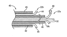
*도 3을 참조로, 도 1에 따른 2개의 개별 전극 어셈블리(16a, 16b)의 위치설정에 따른 문제점은 내강(lumen) 내부에 보유되는 중심 튜브형 샤프트(18c)를 가지는 단일 전극(40)의 사용을 통해 감소될 수 있으며, 제 1 전극(22a)의 와이어(32) 및 제 2 동심 튜브형 샤프트(42)는 샤프트(18c) 부근에 배치되며 제 2 전극(22b) 샤프트(18c) 와이어(44)와 벽 사이에 보유된다. 와이어(44)는 앞서 개시된 와이어(32)와 유사한 형상으로 조절되고 형성된다. 통상적으로 샤프트(18c, 42)는 금속성이며, 샤프트(18c, 42)보다는 노출된 와이어(32) 사이에 임의의 전류가 흐르도록, 각각 절연 코팅(45, 46)으로 코팅된다.3, the problem with the positioning of the two
앞서 언급된 것처럼, 상기 절연 코팅(46)은 도 1의 전극 어셈블리(16a, 16b)의 샤프트(18a, 18b)의 팁에 인가되어 샤프트(18a, 18b) 사이의 단락 회로에 전류가 집중되지 않고, 전극(22a, 22b)의 와이어의 와이어(32)로부터 흐르게 한다.As noted above, the insulating
단일 전극(40)에 대해 용접 등에 의해 부착된 나란한 샤프트(18a, 18b)를 포함하는 다른 유사한 샤프트 구성이 얻어질 수 있다.Other similar shaft configurations may be obtained, including the
제 1 전극(22a)과 제 2 전극(22b) 사이에 각각 상이한 간극(separation)을 가지는 단일 전극(40)의 키트(kits)가 상이한 크기의 종양 및 상이한 조직 형태에 적합하게 제공될 수 있다.Kits of a
앞서 간략하게 언급된 바와 같이, 도 1 및 도 3의 실시예 중 하나에서, 와이어(32)는 와이어(32)의 단부와 관련된 높은 전류 밀도를 감소시키기 위해 이들의 말단부 상에 샤프트(18c, 42)로부터 제거되는 절연 코팅(46)을 포함할 수 있다.As mentioned briefly above, in one of the embodiments of Figures 1 and 3, the
바람직한 실시예에서, 제 1 및 제 2 전극(22a, 22b)의 와이어는 각지게 서로 엇갈려(도 2에 도시된 것과는 다르게), 전극 어셈블리의 축면(axial view)은 비-오버랩 와이어(32)와 동일하게 이격된다. 이러한 구성은 도 2의 실시예에 적합하나, 2개의 전극 어셈블리(16a, 16b)로 유지하는 것은 어려울 수 있다.In the preferred embodiment, the wires of the first and
전력 오실레이터(28)의 주파수는 종래 기술에서 사용되는 450kHz 보다 낮은 값으로 우선적으로 설정될 수 있다. 도 6을 참조로, 가장 보편적인 100kHz 미만 및 10kHz 보다 낮은 주파수에서, 정상 조직의 임피던스는 종양 조직의 임피던스보다 상당히 크게 증가한다. 이러한 임피던스 차는 본 발명자들은 특정한 이론에 의해 제한되길 원하는 것은 아니지만 종양 및 정상 세포 조직들 사이의 개재 물질(interstitial material)에서의 차로 인한 것으로 여겨진다. 임의의 경우에 있어, 현재로서는 종양 조직의 낮은 임피던스는 약 10kHz 값으로 전력 오실레이터(28)의 주파수를 설정함으로써 상기 조직에서 에너지가 우선적으로 디포짓되도록 이용되는 것으로 여겨진다. 그럼에도, 이러한 주파수 설정치는 본 발명의 모든 실시예에 대해 요구되는 것은 아니다.The frequency of the
이러한 주파수는 심장과 같은 신경 조직을 자극할 수 있지만, 이러한 자극은 본 발명의 양극 설계에 의해 제한된다.While such frequencies can stimulate nerve tissue such as the heart, such stimulation is limited by the bipolar design of the present invention.
도 5를 참조로, 전극(22a, 22b)의 로컬 환경은 상기 영역에서 병터(14)의 가열을 실질적으로 감소하는, 하나의 전극 부근의 혈관 등의 존재에 따라 상이할 수 있다. 따라서, 다른 전극(22a, 22b) 부근의 전류 밀도를 변화시키지 않고 하나의 전극(22a, 22b) 부근의 전류 밀도를 증가시키는 것이 바람직하다. 이는 본 발명의 상이한 방식에 이용되는 종래 기술에 사용되는 형태의 피부 접촉 플레이트(50)의 사용에 의해 달성된다. 본 명세서에서 사용되는, 접촉 플레이트(50)란 용어는 임의 넓은 도체로 간주될 수 있으나, 환자 피부의 넓은 영역에 대한 접촉으로 제한될 필요는 없다.5, the local environment of the
도 5의 실시예에서, 접촉 플레이트(50)는 전극(22a, 22b)의 온도에 따라 스위치(53)에 따른 전력 오실레이터(28)의 출력 또는 접지로 가변 저항(52)을 통해 참조될 수 있다. 일반적으로, 스위치(53)는 온도 센서(30)가 전극(22a)보다 전극(22b) 상에서 높은 온도를 나타낼 때 전력 오실레이터(28)의 출력에 가변 저항(52)의 자유 단부를 접속한다. 반대로, 스위치(53)는 온도 센서(30)가 전극(22a)보다 전극(22b) 상에서 낮은 온도를 나타낼 때 가변 저항(52)의 자유 단부를 접지에 접속한다. 전극(22a, 22b)의 온도 비교는 도 2를 참조로 앞서 개시된 것과 유사하게, 최대치 검출 회로(34a, 34b)를 통해 이루어진다. 스위치(53)는 업계에 공지된 형태의 비교기-구동, 고체형 스위치일 수 있다.5, the
각각 전극(22a, 22b)의 온도 센서(30)에 접속되는 최대치-검출 회로(34a, 34b)의 출력은 가변 저항(52)의 설정치를 제어하는데 이용될 수 있다. 스위치(53)가 전력 오실레이터(28)의 출력에 저항(52)을 접속시킬 때, 최대치 검출 회로(34a, 34b)는 전극(22b)이 비교적 뜨거워짐에 따라 저항(52)의 저항값을 감소시키는 역할을 한다. 반대로, 스위치(53)가 저항(52)을 접지에 접속시킬 때, 최대치 검출 회로(34a, 34b)는 전극(22a)이 비교적 뜨거워짐에 따라 저항(52)의 저항값을 감소시키는 역할을 한다. 따라서 스위치(53)와 가변 저항(52)의 작용은 전극(22a, 22b)의 온도를 균일화시키기 위해 시도되는 것이다.The outputs of the maximum-
전극(22a)이 혈관과 같은 히트 싱크(heat sink)에 근접해 있는 경우, 전극(22b)이 아닌, 전극(22a)의 온도 센서(30)가 유사한 값을 나타낼 때, 최대치 검출 회로(34a)의 출력은 최대치 검출 회로(34b)의 출력보다 낮다.When the
저항(52)은 업계에 공지된 기술에 따라 고체형 소자로서 구현되며, 최대치 검출 회로(34a, 34b)의 출력은 고체형 소자의 바이어스 및 저항 또는 앞서 개시된 균일화를 제공하는 전류 제어 전압원 변조 또는 스위칭 부재의 듀티-사이클 변조를 제어한다.The
도 7을 참조로, 이러한 원리들은 전극(22a, 22b)의 각각의 와이어(32)가 전극 어셈블리(16a, 16b) 내에서 전기적으로 절연되고 전력 오실레이터(28) 또는 그의 리턴에 접속되는 가변 저항(54)을 통해 스위치(53)에 의해 개별 공급부에 따라 구동되는 시스템에 적용될 수 있다. 이와 관련하여 전극(22a, 22b) 사이에서 도전성 경로가 아닌 전기적으로 절연된 수단들은 전력원 또는 제어 전자장치와의 접속 이전에 조직을 통해 제외된다. 앞서 주지한 바와 같이, 위상 차는 전극 와이어(32) 사이의 전류 흐름 경로를 더욱더 제어하기 위해 스위치(53)로부터 개별 공급부 사이에서 이용될 수 있다. 이러한 위상 차는 예를 들어, 임의의 스위칭 패턴이 생성되도록, 컴퓨터 프로그램에 따라 동작하는 특정화된 파형 발생기에 의해 또는 위상 이동을 생성하는 복합 저항(complex resistance)에 의해 생성된다. 저항(54) 값은 제어기(56) 상에서 동작하는 프로그램에 의해 개시된 것처럼 변한다. 이를 위해, 가변 저항(54)은 업계에 공지된 기술에 따라 MOSFET과 같은 고체형 소자를 사용하여 구현된다.7, these principles apply to a variable resistor (not shown) in which each
마찬가지로, 제어기(56)에 의해 제어되는 유사한 가변 저항(54)은 접촉 플레이트(50)를 구동시킨다.Likewise, a similar
제어를 위해, 제어기(56)는 라인(58)으로 도시된 것처럼 각각의 와이어(32)의 온도 센서(30)(상기 개시됨)로부터의 입력들을 수신한다. 와이어(32) 상의 전류의 개별적 제어는 종양(12)에 대한 전류 흐름의 추가적 제어가 수축 혈관 또는 임의의 하나의 와이어 부근을 가열하도록 응답하게 한다.For control purposes, the
도 8을 참조로, 하나의 가능성 있는 제어 알고리즘은 프로세스 블록(60)에 의해 도시된 것처럼 온도 센서(30)를 스캔한다. 각각의 온도 센서(30)에 대해, 와이어(32)에서의 온도가 조직 탄화 포인트 이하의 '천정치(ceiling value)' 이상이면, 와이어에서의 전압은 감소된다. 이러한 '햄머링 다운(hammering down)' 프로세스는 모든 와이어의 모든 온도가 천정치 이하일 때까지 반복된다.With reference to Fig. 8, one possible control algorithm scans the
다음 프로세스 블록(62)에서, 각각의 전극(22a, 22b) 상의 와이어들의 평균 온도가 검출되고 접촉 플레이트(50)의 전압은 이러한 평균 값이 점차적으로 균일화되도록 조절된다. 접촉 플레이트(50)의 전압은 보다 높은 평균치를 가지는 전극(22)의 전압을 향해 이동한다.In the
다음 프로세스 블록(64)에서, 프로세스 블록(60)의 햄머링 다운 프로세스는 와이어가 와이어의 천정치 값 이상으로 상승하지 않도록 반복된다.At the
다음 프로세스 블록(66)에서, 프로세스 블록(66)의 발생시마다 차례로 하나의 와이어가 검사되고, 와이어의 온도가 천정치 값 이하의 '바닥치(floor value)' 보다는 낮지만, 종양에 원하는 전력을 제공할 정도로는 충분히 높은 경우, 와이어(32)에서의 전압은 다른 전극(22)의 와이어 전압으로부터 점차적으로 멀리 이동한다. 반대로, 와이어(32)가 바닥치 이상인 경우, 아무런 동작도 취해지지 않는다.At the
점차적으로, 각각의 와이어(32)는 개별적인 전압 제어에 의해 바닥 및 천정 범위 내에서 조절되는 온도를 가질 수 있다. 이러한 프로세스는 온도의 제어 파라미터뿐만 아니라 예를 들어 임피던스를 포함하는 다른 원하는 제어 파라미터에 적용될 수 있다.Gradually, each
도 7에 도시된 것처럼, 이러한 프로세스는 명료성을 위해 접속부들은 도시되지 않은 제 3 전극 세트(22c)를 포함하는 임의의 수의 전극(22)으로 연장될 수 있다.As shown in FIG. 7, this process may be extended to any number of electrodes 22, including the third set of
본 발명은 우산형 프로브들과 관련하여 개시되었지만, 본 발명의 기본 원리는 표준형 니들 프로브를 사용할 수도 있다. 또한, 본 발명은 2개의 전극 세트로 제한되지 않으며, 전류 흐름이 전극 세트들 사이에서 두드러지게 나타나는 다수의 전극 세트를 이용할 수도 있다. 우산형 전극의 와이어 수는 마찬가지로 3개로 제한되지 않으며 본 발명을 이용하기에 적합한 상업적으로 이용가능한 프로브는 10개 와이어 버전을 포함한다. 또한, 전극의 최대 온도는 앞서 개시된 예에서 제어를 위해 사용되었지만, 본 발명은 최대 또는 평균 온도를 사용하거나 임피던스를 측정하거나 예정된 스위칭 시간을 이용하는 방식을 제어하도록 등가적으로 보정될 수 있다.Although the present invention has been described in the context of umbrella-type probes, the basic principles of the present invention may use standard needle probes. The present invention is also not limited to a set of two electrodes, and a plurality of electrode sets may be used in which the current flow appears prominently between the electrode sets. The number of wires of the umbrella electrode is likewise not limited to three, and commercially available probes suitable for use with the present invention include a ten wire version. Further, although the maximum temperature of the electrodes is used for control in the previously described example, the present invention can be equivalently calibrated to control the manner in which the maximum or average temperature is used, the impedance is measured, or the predetermined switching time is used.
Ⅱ. 다중형 Ⅱ. Multi-media 단극Unipolar 전극 동작 Electrode operation
도 9를 참조로, 다중형 단극 시스템(70)은 무선주파수 신호가 단일 극 이중 쓰로우(single pole double throw) 스위치(74)의 극(pole)에 접속되는 전력 출력(72)을 가지는 전력 오실레이터(28)를 제공한다. 스위치(74)는 20kHz 이상의 속도에서 스위칭되는 것으로, 제한되지는 않지만, 바람직하게 업계에 공지된 기술에 따라 고체(solid-state) 스위치로서 바람직하게 구현된다.9, a multi-pole single-
스위치(74)의 제 1 쓰로우(throw)(76)는 전기적으로 접속된 우산 살들(tines)과 관련하여 앞서 개시된 것처럼 우산형 전극인 제 1 전극(22a)과 접속된다. 적어도 하나의 살은 온도 센서(30a)를 포함할 수 있다.The
스위치(74)의 제 2 쓰로우(78)는 온도 센서(30b)를 가지는 제 2 전극(22b)에 접속된다.The second through-
전극(22a, 22b)은 상기 개시된 바와 같이 종양 볼륨의 측면에 배치되거나 또는 요구에 따라 각각의 종양들에 배치될 수 있다. 단일의 종양이 치료되는 경우, 전극(22a, 22b)은 전극(22a, 22b) 살들의 연장 반경이 직경의 3배 미만이 도록 서로 근접해 있다. 양극 실시예와 반대로, 다중형 단극 전극 동작에서는 프로브가 삽입되는 배향이 제한되지 않는다. 또한, 개시된 기술은 임의의 수의 전극으로 연장될 수 있다.
일 실시예에서, 온도 센서(30a, 30b)로부터의 신호들은 제어기(56)에 의해 수신되어, 상기 제어기(56)는 비례/적분(PI)형 제어기(56)에 의해 수신되는 온도차 신호가 생성되도록 온도들을 차감한다. PI 제어기들은 업계에 공지되어 있으며 제 1 제어 상수(K1)와 입력차 신호의 곱 더하기 제 2 제어 상수(K2)와 입력차 신호의 적분의 곱의 함수인 출력 신호를 생성한다. 이 경우 PI 제어기(56)는 하기에 개시되는 추가의 특성을 가지는 전기적 사각파(square wave)로서 구형되는 제어 신호(80)를 생성한다.In one embodiment, signals from
온도차 신호에 대한 것으로, PI 제어기는 임피던스, 온도, 전력, 절대 시간(전극들 간의 정규 스위칭(regular switching)에 대해), 또는 하나 이상의 전극에 대한 임피던스, 온도 또는 전력들 간의 차 및 다른 유사한 제어 입력들을 포함하는, 다른 다양한 제어 입력을 허용한다.For a temperature difference signal, the PI controller may be configured to measure impedance, temperature, power, absolute time (for regular switching between electrodes), or impedance, temperature or power differences for one or more electrodes and other similar control inputs , ≪ / RTI >
택일적으로, PI 제어기에 대해, 임의의 다른 가능한 제어 메커니즘이 2개 이상의 프로브에 전력을 분산시키도록 수행될 수 있다.Alternatively, for the PI controller, any other possible control mechanism may be performed to distribute power to two or more probes.
도 10을 참조로, 일반적으로 제어 신호(80)의 사각파는 전극(22a)에 대한 스위칭 패턴(82a) 및 전극(22b)에 대한 스위칭 패턴(82b)을 생성하기 위해 스위치(74)의 극의 동작을 제어한다. 스위칭 패턴(82a, 82b)은 스위치(74)의 극의 위치를 나타내며 각각의 전극(22a, 22b)에서 출력(72)의 무선주파수 파형의 변조 고저(modulation envelope)가 나타난다. 스위치(74)의 극이 쓰로우(76)에 접속되는 시간 동안, 파형(82a)은 무선주파수 전력이 전극(22a)에 공급되는 것을 나타내는 하이 상태(high state)에 있게 된다. 반대로, 스위치(74)의 극이 쓰로우(78)에 접속되면, 파형(82b)은 무선주파수 에너지가 전극(22b)에 공급되는 것을 나타내는 하이가 된다.10, a square wave of the
바람직한 실시예에 도시된 것처럼, 신호(82a, 82b)는 전극(22a, 22b) 중 단지 하나의 전극만이 순간적으로 제공된 전력을 수신하고 전력 오실레이터(28)로부터의 전력이 완전히 이용되는 것을 나타내는 정확한 보완물들(complements)이다. 즉, 전극(22a)에 에너지가 공급될 때, 전류 흐름은 단지 전극(22a)과 접촉 플레이트(50) 사이(도 9에 화살표 84a로 도시됨)에서만 이루어진다. 반대로, 전극(22b)에 에너지가 공급되면, 전극 흐름은 전극(22b)과 접촉 플레이트(50) 사이(도 9에 화살표 84b로 도시됨)에서만 이루어진다. 주어진 시간에 전극들(22a, 22b) 중 단지 하나의 전극에 에너지가 공급되면 전극(22a) 부근의 병터 볼륨(90a) 또는 전극(22b) 부근의 병터 볼륨(90b)이 손상되는 경향이 있을 수 있고, 전극(22a, 22b)에 동시적으로 에너지가 공급되는 경우 다른 방식으로 손상이 발생할 수 있는 것에 대하여 보호되지 않는다. 그러나 전극(22a, 22b)의 "온(on)" 상태의 중첩은, 상기 중첩 기간이 비중첩 기간에 비해 짧은 경우 허용될 수 있다.As shown in the preferred embodiment, the
전극(22a)이 활성화되는 동안의 시간 주기(94a)가 전극(22b)이 활성화되는 동안의 시간 주기(94)와의 비로 표현되며, 이는 '듀티-사이클'로 정의된다. PI 제어기(56)의 출력을 형성하는 제어 신호(80)는 상기 듀티 사이클을 제어하여, 낮은 온도를 가지는 전극(22a, 22b) 중 하나에 전력이 우선적으로 향하게 된다. 이런 방식으로, 제어기(56)는 2개의 전극(22a, 22b) 각각의 온도가 균등해지게 작용한다. 선택적으로, 듀티-사이클은 접속된 한 쌍의 전극들 사이에서 소모되는 전력 또는 접속된 한 쌍의 전극들 사이의 임피던스에 기초하여 제어될 수 있다. 듀티-사이클이 조절되는 속도는 온도차와 관련되며 앞서 개시된 K1 및 K2의 설정치에 의해 제어되고 실제 온도가 전력의 스위칭으로 순간적으로 편향되는, 전극(22a, 22b)에서의 평균 온도를 반영하도록 조절된다.The
스위치(74)의 스위칭 주파수는 조직의 냉각 시간 보다 빠르게 선택된다(예를 들어, 2Hz 이상). 10kHz 이상 및 약 20kHz의 빠른 스위칭 속도는 신경 및 조직, 특히 심장 조직을 자극할 수 있는 저주파수 성분을 차단하는데 바람직하다. 스위칭은 과도 전류를 방지하기 위해 무선주파수 전력원에 의해 제공되는 신호의 제로-크로싱(zero-crossings)시 우선적으로 수행된다.The switching frequency of the
또한, PI 제어기는 임계(threshold) 온도(약 95℃)가 비율은 유지하면서 주기(94a, 64b)를 동시적으로 감소시킴으로써 도달될 때 전극(22a, 22b)에 전달되는 평균 전력을 감소시키는 제한기(limiter)를 제공할 수 있다. 이 경우, 패턴(82a, 82b)은 더 이상 보완되지 않지만 여전히 비중첩의 하이 상태를 갖는다.The PI controller also has a limit to reduce the average power delivered to the
무선주파수 전력원의 전력 출력은 전극(22a, 22b)의 온도 또는 임피던스에 의해 추가로 제어될 수 있다. 본 실시예에서, 패턴(82a, 82b)은 보완된다. 스위치는 전극(22a, 22b)의 온도가 균등해지는 방식으로 제어된다. 무선주파수 전력원의 전력 출력은 전극(22a, 22b)의 평균 온도가 설정 온도, 통상적으로는 탄화(charring) 및 보일링(boiling)이 발생하는 온도 이하가 되도록 조절된다.The power output of the radio frequency power source may be further controlled by the temperature or impedance of the
도 9에 도시된 선택적 실시예에서, 온도 센서(30a, 30b)는 점선 라인(96)으로 도시된 것처럼 단일 극 이중 쓰로우(single pole double throw) 스위치인 제 2 스위치(98)로 라우팅될 수 있으며, 상기 스위치(98)의 극은 표준 전력 오실레이터(28) 상의 온도 입력에 접속된다. 이 경우, 전력 오실레이터(28)는 스위치(74)의 동작에 따라 교체되는, 주어진 온도 프로브(30a 또는 30b)로부터 수신된 온도의 함수로서 출력 전압 또는 전류를 감소시키도록 직접 조절될 수 있다. 따라서, 전력 오실레이터(28)가 전극(22a)에 전력을 전달하는 시간 동안, 전력 오실레이터는 적절한 제어를 위해 온도 센서(30a)로부터 온도를 수신한다. 다음 스위치(74) 상태가 변하고 전력 오실레이터가 전극(22b)에 접속될 때, 전력 오실레이터는 온도 센서(30b)로부터 온도 신호를 수신한다.9, the
도 11을 참조로, 스위치(74)에 다수의 종양(12, 12') 내에 니들 전극으로 도시되는, 임의의 수의 전극(22a, 22b, 22c)이 제공될 수 있다. 따라서 본 발명은 한 순간에 종양 부근의 위치에 임의의 수의 전극들을 위치시킨 다음 전극들을 이동시킬 필요 없이, 조합된 열 작용으로 실질적으로 볼륨을 동시적으로 치료하는 장점을 제공한다.Referring to Figure 11,
도시된 것처럼, 스위치(74)는 도 12에 도시된 패턴(82c, 82d, 82e)에 따라 변조된 무선주파수 에너지를 제공하기 위해 각각의 전극(22a, 22b, 22c)에 접속되는 하나의 쓰로우를 가지는 단일 극 삼중 쓰로우(single pole triple throw) 스위치이다. 스위칭 패턴(82c, 82d, 82e)은 3개의 파형의 듀티-사이클이 가장 낮은 온도 전극(22)으로 비례하게 전력을 이동시키도록 독립적으로 제어되어(82a, 82b, 82c) 비중첩의 온(on) 시간을 갖지만 더 이상 보완되지 않는다는 것을 제외하고는, 앞서 개시된 스위칭 패턴(82a, 82b)과 유사하다. 이상적으로, 하나 이상의 전극(22)이 임계치 이하의 온도를 가지는 경우, 스위칭 패턴들(82c, 82d, 82e) 중 하나는 모든 시간에서 온(on)이 된다. 소정의 제어 알고리즘은 주기적이며, 여기서 전력은 임의의 프로브에 제공되지 않는다. 이 경우, 다수의 쓰로우 스위치의 극은 임의의 프로브와 접속되지 않거나 또는 전력을 소모하는 소정의 부재에 접속된다.As shown, the
Ⅲ. 다중형 갈퀴 동작 Ⅲ. Multipurpose rake motion
도 13을 참조로, 전극(101)의 선택적 실시예가 도시된다. 상기 도 7을 참조로 개시된 것처럼, 프로브 또는 전극(101)은 다수의 갈퀴(100, 102, 104)를 포함하며, 이들 각각은 예를 들어 전기적 절연부(106)를 통해 다른 갈퀴들과 전기적으로 절연되며, 이들 각각은 갈퀴(100, 102, 104)와 전기적으로 절연될 수 있는 단일의 샤프트(107) 내에 보유된다. 우산형 구조를 제공하도록 바깥방향으로 굽은 갈퀴(100, 102, 104)는 평행한 구조로 배열되거나 다르게 구성될 수 있다. 개개의 갈퀴(100, 102, 104)는 단일 극 다중-쓰로우 스위치(108)에 결합되며, 상기 극은 RF 전력원(28)에 접속된다. 쓰로우의 수는 전극(101)의 갈퀴의 수와 동일하여, 도시된 것처럼 3중 쓰로우 스위치가 된다. 접촉 플레이트 또는 접지 패드(50)가 제공된다. 동작시, 프로브(101) 각각의 갈퀴(100, 102, 104)는 활성(active) 갈퀴와 접지 패드(50) 사이에, 단극 RF 절제술이 제공되도록 개별적으로 활성화될 수 있다. 단일 극 다중-쓰로우 스위치(108)에 결합되는 제어기(56)는 활성화 시간 및 다른 변수들뿐만 아니라, 갈퀴(100, 102, 104) 사이의 스위칭을 제어하도록 제공될 수 있다. 앞서 개시된 것처럼, 온도 센서(30)는 센서(30)로부터 수신된 온도 판독치, 또는 앞서 개시된 것처럼, 임피던스, 전력, 절대 시간, 또는 하나 이상의 갈퀴 또는 유사한 제어 입력의 임피던스, 온도, 또는 전력의 차와 같은 다른 파라미터들에 기초하여 갈퀴(100, 102, 104)들 사이를 스위칭하는 PID 제어기인 제어기(56)에 제공되는 온도 피드백 및 각각의 갈퀴(100, 102, 104) 상에 위치될 수 있다. 하나의 접지 패드(50)가 도시되었지만, 다수의 접지 패드가 제공될 수 있으며, 접지 패드는 하기 개시되는 것처럼, 스위치를 이용하여 동작이 전환될 수 있다. 또한, 샤프트(107)가 전력원(28)에 선택적으로 접속될 수 있다. 갈퀴(100, 102, 104) 각각은 전기적으로 독립적이며 개별적으로 작동하기 때문에, 갈퀴들 사이에는 전기적 상호작용이 없고 예를 들어, 제거 영역의 중심부 치료 개선이 실현될 수 있다.Referring to Fig. 13, an alternative embodiment of
도 14를 참조로, 상기 개시된 전극(101)의 또 다른 실시예가 도시된다. 여기서 프로브는 짝수의 갈퀴(100, 102, 104, 110)를 포함하며, 이들 각각은 앞서 설명된 바와 같이 절연부(106)를 통해 인접한 갈퀴들과 고립되거나 또는 전기적으로 절연된다. 갈퀴(100, 102, 104, 110)는 이중 극 다중-쓰로우 스위치와 각각 결합되며, 여기서 쓰로우의 수는 프로브(101)에 있는 갈퀴 수의 절반으로 결정되며, 도면에서는 2중 극 이중-쓰로우 스위치가 도시된다. 이중 극 이중 쓰로우 스위치(128)의 제 1극은 접지 접속부(114)에 결합되는 반면 제 2 극(130)은 접지 접속부(114)에 참조되는 RF 전력원(28)에 결합된다.Referring to Fig. 14, another embodiment of the above-described
도 15를 참조로, 대향되는 쌍의 갈퀴(100, 104 및 102, 110) 각각은, 동작시, 각각의 쌍의 갈퀴들 사이에 양극 절제술이 제공되도록 제어기(56)에 의해 활성화된다. 대향되는 쌍의 갈퀴들을 스위칭함으로써, 고온 스위칭 양극 병터가 갈퀴의 중심부에 형성될 수 있다.Referring to Fig. 15, each of the opposed pairs of
도 13을 참조로 상기 개시된 것처럼, 각각의 갈퀴(100, 102, 104, 110)는 제어기(56)에 피드백을 제공하는 온도 센서(30)를 포함할 수 있으며, 상기 피드백을 기초로, 원하는 레벨에서 전력 및 온도 레벨을 유지하기 위해 다양한 쌍의 갈퀴들 사이가 스위칭될 때를 결정할 수 있다. 도시되지는 않았지만, 3중의 쓰로우가 사용되어 선택된 레벨에서 전력 및 온도를 유지하도록 원하는 대로 갈퀴들을 비활성화시키는 개방 접속부가 제공된다.Each
4-갈퀴 프로브에 대해 도시되었지만, 10개 갈퀴를 가지는 실질적으로 원형의 어레이 프로브가 바람직하며, 이는 정반대로 대향되는 쌍의 갈귀들이 순차적으로 활성화되는 스위칭 패턴을 갖는다. 앞서 개시된 것처럼, 이런 방식의 스위칭은 갈퀴들의 중심부에 고온 스위칭 양극 병터를 야기한다. 또한, 짝수의 갈퀴들이 도시되었지만, 홀수의 갈퀴들을 포함하는 원형 어레이가 제공될 수 있고, 이는 실질적으로 대향된 오프셋 갈퀴들 사이에 스위칭이 제공된다.Although shown for a four-rake probe, a substantially circular array probe with ten rake is preferred, which has a switching pattern in which the opposite pairs of mags are sequentially activated. As previously described, switching in this manner causes a high temperature switching anode pole in the center of the rake. Also, although an even number of rake is shown, a circular array containing odd rake may be provided, which provides switching between substantially opposed offset rake.
도 16을 참조로, RF 프로브(101)의 또 다른 실시예가 도시된다. 여기서, 각각의 갈퀴(100, 102, 104)는 절연부(106)로 갈퀴들이 서로 전기적으로 절연된다. 각각의 갈퀴(100, 102, 104)는 각각 단일 극 삼중 쓰로우 스위치(114, 116, 118)에 결합된다. 특정하게 단일 극 삼중 쓰로우 스위치(114)를 참조로, 극(132)은 갈퀴(100)에 접속되며 쓰로우(134, 136, 138)는 RF 전력원(28), 접지 접속부(114), 및 전기적 개방 위치에 각각 접속된다. 각각의 스위치(114, 116, 118)는 제어기(56)에도 결합되어, 온도 센서(30)로부터의 피드백 또는 앞서 개시된 다른 형태의 피드백을 기초로, 갈퀴들이 RF 전력원(28)에 접속되는지, 접지 접속부(114)에 접속되는지, 개방된 채 유지되는지를 검출한다. 따라서 양극 절제술이 쌍의 갈퀴들(100, 102, 104) 사이에 제공될 수 있다. 접지 패드(50)가 제공될 수 있으며 선택적으로 단일 극 단일 쓰로우 스위치(120)를 통해 단극 절제술을 가능케하는 접지 접속부(114)에 선택적으로 결합된다. 임의의 갈퀴(100, 102 또는 104)로부터 단극 절제술을 제공하기 위해, 제어기(56)는 임의의 스위치(114, 116, 118)를 활성화시켜 RF 공급원(28)에 갈퀴(100, 102 또는 104)를 연결할 수 있고, 반면 스위치(120)는 회로 접지 접속부(114)에 접지 패드(50)가 접속되도록 활성화된다. 선택적으로, 갈퀴(100, 102, 104) 각각은 RF 전력원(28)에 동시적으로 접속되어 프로브의 모든 갈퀴들이 동시적으로 활성화되는 종래의 절제술을 제공할 수 있다. 통상적으로, 단극 및 양극 절제술은 주어진 치료 상황에 적합한 전력 분포를 제공하기 위해 조합될 수 있다. 또한, 상이한 애플리케이션 패턴들 사이에서의 신속한 스위칭에 의해, 프로브 구조 변화없이 전력 디포지션이 제어될 수 있다.16, another embodiment of the
도 17을 참조로, RF 프로브(101)의 또 다른 실시예가 도시된다. 여기서 일련의 접지 패드(50a, 50b, 50c)는 단일 극 단일 쓰로우 스위치(120, 122, 124)를 통해 접지 접속부(114)에 선택적으로 접속된다. 이러한 시스템의 동작은 도 15를 참조로 앞서 설명되었다. 그러나 여기서, 제어기(56)는 다양한 방향 및 다양한 전력 레벨에서의 전류 흐름을 조장하기 위해 다양한 접지 패드들(50a, 50b, 50c) 사이에 선택될 수 있다. 전류 경로의 활성화 및 비활성화는, 열 센서(30)로부터의 피드백 또는 앞서 개시된 다른 형태의 피드백을 기초로 제어기(56)에 의해 검출될 수 있다. 또한, 열 센서(30)는 접지 패드들(50a, 50b, 50c)과, 또는 앞서 개시된 임의의 형태의 접지 패드와 결합될 수 있으며, 센서들로부터의 온도 판독치는 스위칭 파라미터를 검출하는데 이용될 수 있다. 유사하게, 선택된 갈퀴와 선택된 접지 패드 사이의 임피던스가 스위칭 파라미터로서 이용될 수도 있다. 전극과 다중의 접지 패드들 사이의 다양한 다른 절제술 프로세스는 "독립적으로 제어가능한 접지 패드 도체들을 갖춘 무선주파수 절제술"이란 명칭으로 2004년 5월 11일 출원된 공동계류중인 가특허출원 60/569,896호에 개시되어 있으며, 이는 독립적으로 제어가능한 접지 패드 및 이러한 장치를 제어하는 방법에 대한 설명을 위해 본 발명에 참조된다. 전극들 및 접지 패드들 사이의 스위칭을 위해 개시된 방법은 본 명세서에서 개시된 것처럼 개별 갈퀴들과 접지 패드 사이에 적용될 수 있다.17, another embodiment of the
전극의 특정한 실시예들이 도시되고 개시되었지만, 전극들은 전기적으로 절연된 다양한 개수의 갈퀴들로 구성될 수 있고, 다양한 형태의 스위칭 장치가 상기 갈퀴들 사이에 제공될 수 있다. 또한, 임의의 전극에서 일부 갈퀴들은 서로 접속되는 구성이 개시되었지만 갈퀴들이 전기적으로 절연된 구성이 제공될 수도 있다. 또한, 온도 센서 피드백이 도시되고 개시되었지만, 앞서 개시된 임의의 피드백 메커니즘이 전기적으로 절연된 프로브를 갖는 전극과 조합되어 사용될 수 있다. 또한, 단일 전극(101)이 도시되고 개시되었지만, 다중의 전극이 단일 치료에 이용될 수 있고, 각각의 전극은 독립적 또는 다중 제어기에 의해 개별적으로 제어될 수도 있다. 프로브 자체는 우산형 프로브일 수 있으나, 선택적으로 다수의 전기적으로 독립적인 니들들 또는 단일 샤프트에 고정된 갈퀴들을 포함할 수 있다.Although specific embodiments of electrodes are shown and described, the electrodes may be comprised of a plurality of electrically insulated rake pieces, and various types of switching devices may be provided between the rake pieces. Further, although a configuration in which some rakes are connected to each other at any of the electrodes has been disclosed, an arrangement in which the rakes are electrically insulated may also be provided. Also, although temperature sensor feedback is shown and described, any feedback mechanism previously described may be used in combination with an electrode having an electrically insulated probe. Further, although a
본 발명은 본 명세서에 개시된 실시예 및 설명을 제한되는 것은 아니며, 하기 특허청구범위의 범주 내에서 실시예의 일부를 포함하는 변형된 형태의 실시예 및 부재가 조합된 상이한 실시예가 구현될 수 있다. 예를 들어, 스위치는 적절히 동작하고 동작중단되는 다중의 무선주파수 소스를 이용하여 구현될 수 있다. 다수의 전극이 동시적으로 활성화되는 하이브리드 시스템이 고안될 수 있다. 경피적 전극이 개시되었으나, 본 발명은 뜸(cauterizing) 프로브 및 수술(operative) 또는 복강경(laparoscopically) 배치 전극에 적용될 수 있다. It is to be understood that the invention is not to be limited to the disclosed embodiment and description herein and that it is to be understood that the invention may be embodied in many different forms and should not be construed as being limited to the embodiments set forth herein. For example, the switch may be implemented using multiple radio frequency sources that operate properly and stop operating. A hybrid system in which a plurality of electrodes are simultaneously activated can be devised. Although percutaneous electrodes have been disclosed, the present invention can be applied to cauterizing probes and operative or laparoscopically deployed electrodes.
Claims (23)
다수의 갈퀴들을 포함하는 전기 프로브 ― 상기 다수의 갈퀴들 각각은 상기 다수의 갈퀴들 중 다른 갈퀴들과 전기적으로 절연되고, 상기 전기 프로브는 대향되는 이격된 갈퀴들의 쌍들을 포함하며, 상기 쌍들은 갈퀴들의 각각의 쌍 사이의 중앙 치료(treatment) 영역 주변에 각을 이루어 이격됨 ― ;
무선주파수 전력원;
상기 대향되는 갈퀴들의 각각의 쌍들에 선택적으로 에너지를 공급하기 위하여 상기 갈퀴들 및 상기 무선주파수 전력원과 통신하는 스위치 장치 ― 상기 스위치 장치는 상기 무선주파수 전력원에 갈퀴들의 쌍 각각을 선택적으로 접속시키고, 상기 갈퀴들의 쌍들 사이의 상기 중앙 영역에 고온 치료 영역을 제공하기 위하여 상기 갈퀴들의 쌍들에 순차적으로 에너지가 공급됨 ―; 및
다수의 접지 패드들 ― 상기 스위치 장치는 접지 접속부에 상기 접지 패드들 중 적어도 하나를 선택적으로 접속하여, 상기 접속된 갈퀴와 상기 접속된 접지 패드 사이에 절제술을 위한 전류를 제공하도록 상기 접지 패드들 및 상기 접지 접속부와 추가로 통신함 ―
을 포함하고,
상기 스위치 장치는 선택된 레벨에서 전력 및 온도를 유지하기 위해 상기 갈퀴들을 비활성화하기 위한 개방 접속부를 추가로 제공하는,
무선주파수 절제술 장치.As a radio frequency resection device,
An electric probe comprising a plurality of rakes, each of the plurality of rakes being electrically insulated from the other rake of the plurality of rake, the electric probe comprising pairs of opposed spaced rake pairs, Spaced angularly about a central treatment area between each pair of the first and second electrodes;
Radio frequency power source;
A switch device in communication with said rake and said radio frequency power source for selectively energizing each pair of said opposing rake, said switch device selectively connecting each pair of rake to said radio frequency power source Wherein the pairs of rake are sequentially energized to provide a hot treatment zone in the central region between the pairs of rake pairs; And
A plurality of ground pads, wherein the switch device selectively connects at least one of the ground pads to a ground connection to ground the ground pads and at least one of the ground pads to provide a current for resection between the connected rake and the connected ground pads. Further communicating with the ground connection;
/ RTI >
The switch device further provides an open connection for deactivating the rake to maintain power and temperature at a selected level,
Radio frequency resection device.
상기 스위치 장치는 접지 접속부와 추가로 통신하며, 상기 스위치 장치는 상기 전력원에 상기 갈퀴들 중 하나를 그리고 상기 접지 접속부에 상기 갈퀴들 중 또 다른 하나를 선택적으로 접속하여 양극 절제술을 제공하는,
무선주파수 절제술 장치.The method according to claim 1,
Wherein the switch device further communicates with a ground connection, the switch device selectively connecting one of the rake to the power source and another one of the rake to the ground connection to provide an anodisation,
Radio frequency resection device.
상기 스위치 장치는 상기 갈퀴들과 통신하며, 상기 무선주파수 전력원은 단지 하나의 갈퀴 및 하나의 접지 패드만을 순차적으로 상기 전력원에 동시에 접속하여, 선택된 갈퀴로부터 절제술을 위한 단극 전류 흐름은 제공하면서, 다른 갈퀴들로부터의 전류 흐름은 차단하는,
무선주파수 절제술 장치.The method according to claim 1,
Wherein the switch device is in communication with the rake wherein the radio frequency power source simultaneously connects only one rake and one ground pad to the power source at the same time to provide a unipolar current flow for resection from the selected rake, The current flow from the other rake is blocked,
Radio frequency resection device.
상기 스위치 장치를 구동하기 위한 제어기를 더 포함하는,
무선주파수 절제술 장치.The method according to claim 1,
Further comprising a controller for driving said switch device,
Radio frequency resection device.
상기 프로브는 적어도 2개의 갈퀴들을 가지는 우산형 전극인,
무선주파수 절제술 장치.5. The method of claim 4,
Wherein the probe is an umbrella electrode having at least two rake members,
Radio frequency resection device.
상기 스위치 장치는 상기 접속된 갈퀴들과 접지 패드들을 변화시키는,
무선주파수 절제술 장치.The method according to claim 1,
Wherein the switch device changes the connected rake and ground pads,
Radio frequency resection device.
상기 스위치 장치는 상기 접속된 갈퀴와 접지 평면 사이의 임피던스, 상기 접속된 갈퀴의 온도, 상기 접지 패드의 온도, 예정된 시간 설정치, 및 상기 접속된 갈퀴와 상기 접지 패드 사이에서 소모되는 전력으로 이루어진 그룹으로부터 선택되는 제어 파라미터에 따라 상기 전력원에 대한 상기 갈퀴들의 상대적인 접속 기간을 제어하는,
무선주파수 절제술 장치.The method according to claim 1,
Wherein the switch device is adapted to switch from the group consisting of the impedance between the connected rake and the ground plane, the temperature of the connected rake, the temperature of the ground pad, the predetermined time setting, and the power consumed between the connected rake and the ground pad Controlling the relative duration of the rake relative to the power source in accordance with a selected control parameter,
Radio frequency resection device.
상기 스위치 장치는 상기 접속된 갈퀴와 접지 평면 사이의 임피던스, 상기 접속된 갈퀴의 온도, 상기 접지 패드의 온도, 예정된 시간 주기, 및 상기 접속된 갈퀴와 상기 접지 패드 사이에서 소모되는 전력으로 이루어진 그룹으로부터 선택되는 파라미터에 따라 스위칭을 제어하는 비례/적분 제어기를 포함하는,
무선주파수 절제술 장치.The method according to claim 1,
The switch device is adapted to switch from the group consisting of the impedance between the connected rake and the ground plane, the temperature of the connected rake, the temperature of the ground pad, the predetermined time period, and the power consumed between the connected rake and the ground pad And a proportional / integral controller for controlling the switching according to the selected parameter.
Radio frequency resection device.
상기 스위치 장치는 추가로 접지 접속부와 선택적으로 통신하고, 상기 스위치 장치는 양극 절제술 및 단극 절제술 중 적어도 하나를 선택적으로 제공하기 위해 상기 접지 접속부에 갈퀴 또는 접지 패드 중 하나를 선택적으로 접속시키는,
무선주파수 절제술 장치.The method according to claim 1,
Wherein the switch device further selectively communicates with a ground connection and the switch device selectively connects one of the rake or ground pads to the ground connection to selectively provide at least one of an anodicectomy and a monodentectomy,
Radio frequency resection device.
Applications Claiming Priority (3)
| Application Number | Priority Date | Filing Date | Title |
|---|---|---|---|
| US10/911,927 | 2004-08-05 | ||
| US10/911,927 US7520877B2 (en) | 2000-06-07 | 2004-08-05 | Radiofrequency ablation system using multiple prong probes |
| PCT/US2005/027751 WO2006017666A2 (en) | 2004-08-05 | 2005-07-29 | Radiofrequency ablation system using multiple-prong probes |
Related Parent Applications (1)
| Application Number | Title | Priority Date | Filing Date |
|---|---|---|---|
| KR1020077005219A Division KR20070050459A (en) | 2004-08-05 | 2005-07-29 | Radiofrequency Ablation System Using a Multi-Raw Probe |
Publications (2)
| Publication Number | Publication Date |
|---|---|
| KR20120101160A KR20120101160A (en) | 2012-09-12 |
| KR101425110B1 true KR101425110B1 (en) | 2014-08-13 |
Family
ID=35549026
Family Applications (2)
| Application Number | Title | Priority Date | Filing Date |
|---|---|---|---|
| KR1020127019965A Expired - Lifetime KR101425110B1 (en) | 2004-08-05 | 2005-07-29 | Radiofrequency ablation system using multiple-prong probe |
| KR1020077005219A Ceased KR20070050459A (en) | 2004-08-05 | 2005-07-29 | Radiofrequency Ablation System Using a Multi-Raw Probe |
Family Applications After (1)
| Application Number | Title | Priority Date | Filing Date |
|---|---|---|---|
| KR1020077005219A Ceased KR20070050459A (en) | 2004-08-05 | 2005-07-29 | Radiofrequency Ablation System Using a Multi-Raw Probe |
Country Status (7)
| Country | Link |
|---|---|
| US (1) | US7520877B2 (en) |
| EP (1) | EP1791485B1 (en) |
| JP (2) | JP4926961B2 (en) |
| KR (2) | KR101425110B1 (en) |
| AU (1) | AU2005271471B2 (en) |
| CA (1) | CA2575792C (en) |
| WO (1) | WO2006017666A2 (en) |
Families Citing this family (122)
| Publication number | Priority date | Publication date | Assignee | Title |
|---|---|---|---|---|
| US6994706B2 (en) | 2001-08-13 | 2006-02-07 | Minnesota Medical Physics, Llc | Apparatus and method for treatment of benign prostatic hyperplasia |
| EP1732594A4 (en) * | 2004-03-18 | 2007-10-17 | St Lukes Hospital | Method for the delivery of sustained release agents |
| WO2005110263A2 (en) * | 2004-05-11 | 2005-11-24 | Wisconsin Alumni Research Foundation | Radiofrequency ablation with independently controllable ground pad conductors |
| CN101198288A (en) * | 2005-01-18 | 2008-06-11 | S.D.M.H.有限公司 | Biological tissue thermal ablation apparatus and method using spherical ablation patterns |
| US7806893B2 (en) * | 2005-04-26 | 2010-10-05 | Boston Scientific Scimed, Inc. | Apparatus and method for making a spherical lesion |
| US20070055225A1 (en) * | 2005-09-07 | 2007-03-08 | Dodd Gerald D Iii | Method and apparatus for electromagnetic ablation of biological tissue |
| US20070179495A1 (en) * | 2006-01-27 | 2007-08-02 | Mitchell Mathew E | Combination electrosurgery |
| US7942872B2 (en) * | 2006-02-27 | 2011-05-17 | Moshe Ein-Gal | Blended monopolar and bipolar application of RF energy |
| US20070260240A1 (en) | 2006-05-05 | 2007-11-08 | Sherwood Services Ag | Soft tissue RF transection and resection device |
| US8700176B2 (en) * | 2006-07-27 | 2014-04-15 | Pollogen Ltd. | Apparatus and method for non-invasive treatment of skin tissue |
| US20080051777A1 (en) * | 2006-08-28 | 2008-02-28 | Dieter Haemmerich | Radiofrequency ablation device for reducing the incidence of skin burns |
| US7927329B2 (en) * | 2006-09-28 | 2011-04-19 | Covidien Ag | Temperature sensing return electrode pad |
| US20080140113A1 (en) * | 2006-12-07 | 2008-06-12 | Cierra, Inc. | Method for sealing a pfo using an energy delivery device |
| US20090138011A1 (en) * | 2007-03-13 | 2009-05-28 | Gordon Epstein | Intermittent ablation rf driving for moderating return electrode temperature |
| US20080249523A1 (en) * | 2007-04-03 | 2008-10-09 | Tyco Healthcare Group Lp | Controller for flexible tissue ablation procedures |
| GB0708783D0 (en) * | 2007-05-04 | 2007-06-13 | Gyrus Medical Ltd | Electrosurgical system |
| US8080007B2 (en) | 2007-05-07 | 2011-12-20 | Tyco Healthcare Group Lp | Capacitive electrosurgical return pad with contact quality monitoring |
| US8100898B2 (en) | 2007-08-01 | 2012-01-24 | Tyco Healthcare Group Lp | System and method for return electrode monitoring |
| US10238447B2 (en) | 2008-04-29 | 2019-03-26 | Virginia Tech Intellectual Properties, Inc. | System and method for ablating a tissue site by electroporation with real-time monitoring of treatment progress |
| US10245098B2 (en) | 2008-04-29 | 2019-04-02 | Virginia Tech Intellectual Properties, Inc. | Acute blood-brain barrier disruption using electrical energy based therapy |
| US9283051B2 (en) | 2008-04-29 | 2016-03-15 | Virginia Tech Intellectual Properties, Inc. | System and method for estimating a treatment volume for administering electrical-energy based therapies |
| US11254926B2 (en) | 2008-04-29 | 2022-02-22 | Virginia Tech Intellectual Properties, Inc. | Devices and methods for high frequency electroporation |
| US10702326B2 (en) | 2011-07-15 | 2020-07-07 | Virginia Tech Intellectual Properties, Inc. | Device and method for electroporation based treatment of stenosis of a tubular body part |
| US11272979B2 (en) | 2008-04-29 | 2022-03-15 | Virginia Tech Intellectual Properties, Inc. | System and method for estimating tissue heating of a target ablation zone for electrical-energy based therapies |
| US10117707B2 (en) | 2008-04-29 | 2018-11-06 | Virginia Tech Intellectual Properties, Inc. | System and method for estimating tissue heating of a target ablation zone for electrical-energy based therapies |
| US10272178B2 (en) | 2008-04-29 | 2019-04-30 | Virginia Tech Intellectual Properties Inc. | Methods for blood-brain barrier disruption using electrical energy |
| EP2280741A4 (en) | 2008-04-29 | 2012-06-13 | Virginia Tech Intell Prop | IRREVERSIBLE ELECTROPORATION FOR CREATING TISSUE SCAFFOLDS |
| US8992517B2 (en) | 2008-04-29 | 2015-03-31 | Virginia Tech Intellectual Properties Inc. | Irreversible electroporation to treat aberrant cell masses |
| US9867652B2 (en) | 2008-04-29 | 2018-01-16 | Virginia Tech Intellectual Properties, Inc. | Irreversible electroporation using tissue vasculature to treat aberrant cell masses or create tissue scaffolds |
| US9198733B2 (en) | 2008-04-29 | 2015-12-01 | Virginia Tech Intellectual Properties, Inc. | Treatment planning for electroporation-based therapies |
| DE102008058737B4 (en) * | 2008-09-08 | 2019-12-12 | Erbe Elektromedizin Gmbh | Electrosurgical generator |
| US20100130976A1 (en) * | 2008-11-21 | 2010-05-27 | Smith & Nephew Inc. | Reducing cross-talk effects in an rf electrosurgical device |
| US8632534B2 (en) | 2009-04-03 | 2014-01-21 | Angiodynamics, Inc. | Irreversible electroporation (IRE) for congestive obstructive pulmonary disease (COPD) |
| US11382681B2 (en) | 2009-04-09 | 2022-07-12 | Virginia Tech Intellectual Properties, Inc. | Device and methods for delivery of high frequency electrical pulses for non-thermal ablation |
| US11638603B2 (en) | 2009-04-09 | 2023-05-02 | Virginia Tech Intellectual Properties, Inc. | Selective modulation of intracellular effects of cells using pulsed electric fields |
| WO2014143014A1 (en) | 2013-03-15 | 2014-09-18 | Triagenics, Llc | Therapeutic tooth bud ablation |
| AU2010247874B2 (en) | 2009-05-11 | 2015-05-14 | TriAgenics, Inc. | Therapeutic tooth bud ablation |
| US12514679B2 (en) | 2009-05-11 | 2026-01-06 | TriAgenics, Inc. | Therapeutic tooth bud ablation |
| US10022202B2 (en) | 2013-03-15 | 2018-07-17 | Triagenics, Llc | Therapeutic tooth bud ablation |
| WO2010138919A2 (en) | 2009-05-28 | 2010-12-02 | Angiodynamics, Inc. | System and method for synchronizing energy delivery to the cardiac rhythm |
| US9895189B2 (en) | 2009-06-19 | 2018-02-20 | Angiodynamics, Inc. | Methods of sterilization and treating infection using irreversible electroporation |
| US9095359B2 (en) * | 2009-09-18 | 2015-08-04 | Covidien Lp | Tissue ablation system with energy distribution |
| US9050113B2 (en) | 2010-01-15 | 2015-06-09 | Medtronic Advanced Energy Llc | Electrosurgical devices, electrosurgical unit and methods of use thereof |
| JP6045916B2 (en) * | 2010-02-26 | 2016-12-14 | コーニンクレッカ フィリップス エヌ ヴェKoninklijke Philips N.V. | Interventional ablation device with tissue identification capability |
| GB2480498A (en) | 2010-05-21 | 2011-11-23 | Ethicon Endo Surgery Inc | Medical device comprising RF circuitry |
| WO2012033984A1 (en) | 2010-09-09 | 2012-03-15 | Old Dominion University Research Foundation | Multi-electrode electrical pulse delivery system for treatment of biological tissues |
| EP2627274B1 (en) | 2010-10-13 | 2022-12-14 | AngioDynamics, Inc. | System for electrically ablating tissue of a patient |
| US9737353B2 (en) | 2010-12-16 | 2017-08-22 | Biosense Webster (Israel) Ltd. | System for controlling tissue ablation using temperature sensors |
| WO2012088149A2 (en) | 2010-12-20 | 2012-06-28 | Virginia Tech Intellectual Properties, Inc. | High-frequency electroporation for cancer therapy |
| US9044245B2 (en) | 2011-01-05 | 2015-06-02 | Medtronic Ablation Frontiers Llc | Multipolarity epicardial radiofrequency ablation |
| US9078665B2 (en) | 2011-09-28 | 2015-07-14 | Angiodynamics, Inc. | Multiple treatment zone ablation probe |
| US9414880B2 (en) | 2011-10-24 | 2016-08-16 | Ethicon Endo-Surgery, Llc | User interface in a battery powered device |
| GB201120009D0 (en) | 2011-11-21 | 2012-01-04 | Univ Dundee | Apparatus and method for detaching solid tumours |
| GB201120023D0 (en) | 2011-11-21 | 2012-01-04 | Univ Dundee | Radio frequency surgical probe |
| US9414881B2 (en) | 2012-02-08 | 2016-08-16 | Angiodynamics, Inc. | System and method for increasing a target zone for electrical ablation |
| KR101342906B1 (en) * | 2012-10-25 | 2013-12-19 | 신경민 | Ablation system employing multiple electrodes and control method thereof |
| CN104812324B (en) * | 2012-11-19 | 2018-03-30 | 皇家飞利浦有限公司 | temperature distribution determining device |
| US9204921B2 (en) * | 2012-12-13 | 2015-12-08 | Cook Medical Technologies Llc | RF energy controller and method for electrosurgical medical devices |
| US9364277B2 (en) | 2012-12-13 | 2016-06-14 | Cook Medical Technologies Llc | RF energy controller and method for electrosurgical medical devices |
| MY187052A (en) * | 2013-03-15 | 2021-08-27 | Plasmability Llc | Toroidal plasma processing apparatus |
| US20160242838A1 (en) | 2013-10-22 | 2016-08-25 | Koninklijke Philips N.V. | Temperature monitoring apparatus and method for monitoring a temperature within a tissue |
| US20150272662A1 (en) | 2014-03-28 | 2015-10-01 | Spiration, Inc., d.b.a. Olympus Respiratory America | System and method for predictable deployment of a medical device |
| WO2015175570A1 (en) | 2014-05-12 | 2015-11-19 | Virginia Tech Intellectual Properties, Inc. | Selective modulation of intracellular effects of cells using pulsed electric fields |
| US12114911B2 (en) | 2014-08-28 | 2024-10-15 | Angiodynamics, Inc. | System and method for ablating a tissue site by electroporation with real-time pulse monitoring |
| WO2016100325A1 (en) | 2014-12-15 | 2016-06-23 | Virginia Tech Intellectual Properties, Inc. | Devices, systems, and methods for real-time monitoring of electrophysical effects during tissue treatment |
| US10159524B2 (en) | 2014-12-22 | 2018-12-25 | Ethicon Llc | High power battery powered RF amplifier topology |
| US10368934B2 (en) * | 2015-01-14 | 2019-08-06 | Covidien Lp | Arrangement of multi-channel bipolar electrode zones to minimize leakage and edge effects |
| US10959771B2 (en) | 2015-10-16 | 2021-03-30 | Ethicon Llc | Suction and irrigation sealing grasper |
| WO2017069940A1 (en) | 2015-10-20 | 2017-04-27 | Spiration, Inc., d.b.a. Olympus Respiratory America | Ablation device |
| US10959806B2 (en) | 2015-12-30 | 2021-03-30 | Ethicon Llc | Energized medical device with reusable handle |
| US10856934B2 (en) | 2016-04-29 | 2020-12-08 | Ethicon Llc | Electrosurgical instrument with electrically conductive gap setting and tissue engaging members |
| US10987156B2 (en) | 2016-04-29 | 2021-04-27 | Ethicon Llc | Electrosurgical instrument with electrically conductive gap setting member and electrically insulative tissue engaging members |
| US10751117B2 (en) | 2016-09-23 | 2020-08-25 | Ethicon Llc | Electrosurgical instrument with fluid diverter |
| US10905492B2 (en) | 2016-11-17 | 2021-02-02 | Angiodynamics, Inc. | Techniques for irreversible electroporation using a single-pole tine-style internal device communicating with an external surface electrode |
| US11033325B2 (en) * | 2017-02-16 | 2021-06-15 | Cilag Gmbh International | Electrosurgical instrument with telescoping suction port and debris cleaner |
| US10799284B2 (en) | 2017-03-15 | 2020-10-13 | Ethicon Llc | Electrosurgical instrument with textured jaws |
| US11497546B2 (en) | 2017-03-31 | 2022-11-15 | Cilag Gmbh International | Area ratios of patterned coatings on RF electrodes to reduce sticking |
| US10603117B2 (en) | 2017-06-28 | 2020-03-31 | Ethicon Llc | Articulation state detection mechanisms |
| RU2677559C1 (en) * | 2017-08-17 | 2019-01-17 | Российская Федерация, от имени которой выступает Министерство промышленности и торговли Российской Федерации (Минпромторг России) | Method of friction stir welding of aluminum billets of variable thickness |
| US11490951B2 (en) | 2017-09-29 | 2022-11-08 | Cilag Gmbh International | Saline contact with electrodes |
| US11484358B2 (en) | 2017-09-29 | 2022-11-01 | Cilag Gmbh International | Flexible electrosurgical instrument |
| US11033323B2 (en) | 2017-09-29 | 2021-06-15 | Cilag Gmbh International | Systems and methods for managing fluid and suction in electrosurgical systems |
| US11648047B2 (en) | 2017-10-06 | 2023-05-16 | Vive Scientific, Llc | System and method to treat obstructive sleep apnea |
| EP3709919A1 (en) * | 2017-11-17 | 2020-09-23 | Medtronic Ardian Luxembourg S.à.r.l. | Systems, devices, and associated methods for neuromodulation with enhanced nerve targeting |
| US11607537B2 (en) | 2017-12-05 | 2023-03-21 | Virginia Tech Intellectual Properties, Inc. | Method for treating neurological disorders, including tumors, with electroporation |
| US11311329B2 (en) | 2018-03-13 | 2022-04-26 | Virginia Tech Intellectual Properties, Inc. | Treatment planning for immunotherapy based treatments using non-thermal ablation techniques |
| US11925405B2 (en) | 2018-03-13 | 2024-03-12 | Virginia Tech Intellectual Properties, Inc. | Treatment planning system for immunotherapy enhancement via non-thermal ablation |
| US12390262B2 (en) | 2018-03-13 | 2025-08-19 | Virginia Tech Intellectual Properties, Inc. | Treatment planning system for immunotherapy enhancement via non-thermal ablation |
| US11696791B2 (en) | 2018-09-07 | 2023-07-11 | Cilag Gmbh International | Surgical instrument utilizing drive signal to power secondary function |
| US12035956B2 (en) | 2018-09-07 | 2024-07-16 | Cilag Gmbh International | Instrument tracking arrangement based on real time clock information |
| US11923084B2 (en) | 2018-09-07 | 2024-03-05 | Cilag Gmbh International | First and second communication protocol arrangement for driving primary and secondary devices through a single port |
| US11804679B2 (en) | 2018-09-07 | 2023-10-31 | Cilag Gmbh International | Flexible hand-switch circuit |
| US11871981B2 (en) * | 2018-12-20 | 2024-01-16 | Medtronic, Inc. | Method of power distribution |
| WO2020176751A1 (en) * | 2019-02-27 | 2020-09-03 | Medical Engineering Innovations, Inc. | Radio frequency surgical instruments |
| US11743665B2 (en) | 2019-03-29 | 2023-08-29 | Cilag Gmbh International | Modular surgical energy system with module positional awareness sensing with time counter |
| US11172984B2 (en) | 2019-05-03 | 2021-11-16 | Biosense Webster (Israel) Ltd. | Device, system and method to ablate cardiac tissue |
| AU2020287387B2 (en) | 2019-06-06 | 2024-02-01 | TriAgenics, Inc. | Ablation probe systems |
| US11950835B2 (en) | 2019-06-28 | 2024-04-09 | Virginia Tech Intellectual Properties, Inc. | Cycled pulsing to mitigate thermal damage for multi-electrode irreversible electroporation therapy |
| US12214189B2 (en) | 2019-07-24 | 2025-02-04 | Virginia Tech Intellectual Properties, Inc. | Fourier analysis spectroscopy for monitoring tissue impedance changes and treatment outcome during electroporation-based-therapies |
| USD939545S1 (en) | 2019-09-05 | 2021-12-28 | Cilag Gmbh International | Display panel or portion thereof with graphical user interface for energy module |
| EP4470491A3 (en) | 2020-10-26 | 2025-01-22 | TriAgenics, Inc. | Ablation probe systems |
| US12485279B2 (en) | 2020-11-25 | 2025-12-02 | Virginia Tech Intellectual Properties, Inc. | Methods for modulating temporal infrastructure of pulsed electric fields |
| US12471982B2 (en) | 2020-12-02 | 2025-11-18 | Cilag Gmbh International | Method for tissue treatment by surgical instrument |
| US12235697B2 (en) | 2021-03-30 | 2025-02-25 | Cilag Gmbh International | Backplane connector attachment mechanism for modular energy system |
| US12040749B2 (en) | 2021-03-30 | 2024-07-16 | Cilag Gmbh International | Modular energy system with dual amplifiers and techniques for updating parameters thereof |
| US11980411B2 (en) | 2021-03-30 | 2024-05-14 | Cilag Gmbh International | Header for modular energy system |
| US12369994B2 (en) | 2021-03-30 | 2025-07-29 | Cilag Gmbh International | Modular energy system with multi-energy port splitter for multiple energy devices |
| US11950860B2 (en) | 2021-03-30 | 2024-04-09 | Cilag Gmbh International | User interface mitigation techniques for modular energy systems |
| US11978554B2 (en) | 2021-03-30 | 2024-05-07 | Cilag Gmbh International | Radio frequency identification token for wireless surgical instruments |
| US12004824B2 (en) | 2021-03-30 | 2024-06-11 | Cilag Gmbh International | Architecture for modular energy system |
| US11857252B2 (en) | 2021-03-30 | 2024-01-02 | Cilag Gmbh International | Bezel with light blocking features for modular energy system |
| US11968776B2 (en) | 2021-03-30 | 2024-04-23 | Cilag Gmbh International | Method for mechanical packaging for modular energy system |
| US11963727B2 (en) | 2021-03-30 | 2024-04-23 | Cilag Gmbh International | Method for system architecture for modular energy system |
| US12228987B2 (en) | 2021-03-30 | 2025-02-18 | Cilag Gmbh International | Method for energy delivery for modular energy system |
| US12354186B2 (en) | 2021-04-14 | 2025-07-08 | Cilag Gmbh International | Customization of overlaid data and configuration |
| US12508021B2 (en) | 2021-11-01 | 2025-12-30 | Cilag Gmbh International | Devices, systems, and methods for detecting tissue and foreign objects during a surgical operation |
| US11957342B2 (en) | 2021-11-01 | 2024-04-16 | Cilag Gmbh International | Devices, systems, and methods for detecting tissue and foreign objects during a surgical operation |
| JP7636365B2 (en) | 2022-03-25 | 2025-02-26 | 日本ライフライン株式会社 | Power supply apparatus, electrical medical device system and power supply method |
| US12079460B2 (en) | 2022-06-28 | 2024-09-03 | Cilag Gmbh International | Profiles for modular energy system |
| CN115119375B (en) * | 2022-07-15 | 2024-05-28 | 山东大学 | A multi-mode Langmuir probe three-in-one detection system and detection method |
| CN115177361B (en) * | 2022-08-18 | 2025-09-30 | 上海美杰医疗科技有限公司 | Temperature control system and method for multiple radiofrequency ablation needles |
| KR20240117833A (en) * | 2023-01-26 | 2024-08-02 | 주식회사 스타메드 | Radiofrequency ablation system using no-touch technique and control method thereof |
Citations (4)
| Publication number | Priority date | Publication date | Assignee | Title |
|---|---|---|---|---|
| KR960702279A (en) * | 1993-05-13 | 1996-04-27 | MEDICAL PROBE WITH STYLETS | |
| JPH11505141A (en) * | 1995-05-12 | 1999-05-18 | メディカル・イノベーションズ・コーポレイション | Method and apparatus for electrosurgically accessing a dendritic branch of a gallbladder with an adjustable and scalable needle knife |
| US20020120261A1 (en) * | 2001-02-28 | 2002-08-29 | Morris David L. | Tissue surface treatment apparatus and method |
| US20020156472A1 (en) * | 2000-06-07 | 2002-10-24 | Lee Fred T. | Radio-frequency ablation system using multiple electrodes |
Family Cites Families (7)
| Publication number | Priority date | Publication date | Assignee | Title |
|---|---|---|---|---|
| ATE114441T1 (en) * | 1989-09-07 | 1994-12-15 | Siemens Ag | METHOD AND CIRCUIT ARRANGEMENT FOR MONITORING SEVERAL ELECTRODE AREAS OF THE NEUTRAL ELECTRODE OF AN H.F. SURGICAL DEVICE. |
| US6080150A (en) * | 1995-08-15 | 2000-06-27 | Rita Medical Systems, Inc. | Cell necrosis apparatus |
| JP3636511B2 (en) * | 1995-09-11 | 2005-04-06 | 株式会社セムコ | Electrosurgical equipment |
| US5968041A (en) * | 1998-04-02 | 1999-10-19 | Vida Care, Inc. | Directable thermal energy delivery apparatus |
| US6827714B2 (en) * | 2001-03-07 | 2004-12-07 | Scimed Life Systems, Inc. | Internal indifferent electrode device for use with lesion creation apparatus and method of forming lesions using the same |
| US6740080B2 (en) * | 2001-08-31 | 2004-05-25 | Cardiac Pacemakers, Inc. | Ablation system with selectable current path means |
| WO2005110263A2 (en) * | 2004-05-11 | 2005-11-24 | Wisconsin Alumni Research Foundation | Radiofrequency ablation with independently controllable ground pad conductors |
-
2004
- 2004-08-05 US US10/911,927 patent/US7520877B2/en not_active Expired - Lifetime
-
2005
- 2005-07-29 KR KR1020127019965A patent/KR101425110B1/en not_active Expired - Lifetime
- 2005-07-29 KR KR1020077005219A patent/KR20070050459A/en not_active Ceased
- 2005-07-29 EP EP05804006.4A patent/EP1791485B1/en not_active Expired - Lifetime
- 2005-07-29 AU AU2005271471A patent/AU2005271471B2/en not_active Expired
- 2005-07-29 WO PCT/US2005/027751 patent/WO2006017666A2/en not_active Ceased
- 2005-07-29 CA CA2575792A patent/CA2575792C/en not_active Expired - Lifetime
- 2005-07-29 JP JP2007524992A patent/JP4926961B2/en not_active Expired - Lifetime
-
2011
- 2011-12-19 JP JP2011276946A patent/JP5281140B2/en not_active Expired - Lifetime
Patent Citations (4)
| Publication number | Priority date | Publication date | Assignee | Title |
|---|---|---|---|---|
| KR960702279A (en) * | 1993-05-13 | 1996-04-27 | MEDICAL PROBE WITH STYLETS | |
| JPH11505141A (en) * | 1995-05-12 | 1999-05-18 | メディカル・イノベーションズ・コーポレイション | Method and apparatus for electrosurgically accessing a dendritic branch of a gallbladder with an adjustable and scalable needle knife |
| US20020156472A1 (en) * | 2000-06-07 | 2002-10-24 | Lee Fred T. | Radio-frequency ablation system using multiple electrodes |
| US20020120261A1 (en) * | 2001-02-28 | 2002-08-29 | Morris David L. | Tissue surface treatment apparatus and method |
Also Published As
| Publication number | Publication date |
|---|---|
| CA2575792C (en) | 2011-11-29 |
| CA2575792A1 (en) | 2006-02-16 |
| EP1791485A2 (en) | 2007-06-06 |
| US20050010209A1 (en) | 2005-01-13 |
| KR20070050459A (en) | 2007-05-15 |
| EP1791485B1 (en) | 2014-12-31 |
| JP4926961B2 (en) | 2012-05-09 |
| WO2006017666A2 (en) | 2006-02-16 |
| JP5281140B2 (en) | 2013-09-04 |
| WO2006017666A3 (en) | 2006-03-30 |
| AU2005271471A2 (en) | 2006-02-16 |
| JP2008508946A (en) | 2008-03-27 |
| JP2012101087A (en) | 2012-05-31 |
| AU2005271471A1 (en) | 2006-02-16 |
| KR20120101160A (en) | 2012-09-12 |
| AU2005271471B2 (en) | 2012-01-19 |
| US7520877B2 (en) | 2009-04-21 |
Similar Documents
| Publication | Publication Date | Title |
|---|---|---|
| KR101425110B1 (en) | Radiofrequency ablation system using multiple-prong probe | |
| KR101034682B1 (en) | Radiofrequency Ablation System Using Multiple Electrodes | |
| JP5100947B2 (en) | Multipolar electrode system for radiofrequency ablation | |
| US8216219B2 (en) | Device for electrosurgically destroying body tissue | |
| CN100409822C (en) | Device for electrosurgical hardening of body tissue | |
| US20060074413A1 (en) | Method and apparatus for substantial and uniform ablation about a linear bipolar array of electrodes | |
| CN101188978B (en) | Devices for tissue cautery | |
| US20050096644A1 (en) | Energy delivery optimization for RF duty cycle for lesion creation | |
| WO2009086418A1 (en) | Electrosurgical probe having conductive outer surface to initiate ablation between electrodes | |
| WO2005060853A1 (en) | Ablation probe with temperature sensitive electrode array | |
| US20090125011A1 (en) | Devices, Methods and Kits for Substantial and Uniform Ablation about a Linear Bipolar Array of Electrodes | |
| US20090171339A1 (en) | Electrosurgical probe having current enhancing protrusions | |
| AU2002341571A1 (en) | Radio-frequency ablation system using multiple electrodes | |
| WO2024258920A1 (en) | Devices, systems, and methods for preventing arcing between electrodes for medical procedures | |
| WO2013076440A1 (en) | Radio frequency surgical probe | |
| PT1439792E (en) | Radio-frequency ablation system using multiple electrodes |
Legal Events
| Date | Code | Title | Description |
|---|---|---|---|
| A107 | Divisional application of patent | ||
| A201 | Request for examination | ||
| E13-X000 | Pre-grant limitation requested |
St.27 status event code: A-2-3-E10-E13-lim-X000 |
|
| P11-X000 | Amendment of application requested |
St.27 status event code: A-2-2-P10-P11-nap-X000 |
|
| P13-X000 | Application amended |
St.27 status event code: A-2-2-P10-P13-nap-X000 |
|
| PA0104 | Divisional application for international application |
St.27 status event code: A-0-1-A10-A18-div-PA0104 St.27 status event code: A-0-1-A10-A16-div-PA0104 |
|
| PA0201 | Request for examination |
St.27 status event code: A-1-2-D10-D11-exm-PA0201 |
|
| PG1501 | Laying open of application |
St.27 status event code: A-1-1-Q10-Q12-nap-PG1501 |
|
| E902 | Notification of reason for refusal | ||
| PE0902 | Notice of grounds for rejection |
St.27 status event code: A-1-2-D10-D21-exm-PE0902 |
|
| R17-X000 | Change to representative recorded |
St.27 status event code: A-3-3-R10-R17-oth-X000 |
|
| T11-X000 | Administrative time limit extension requested |
St.27 status event code: U-3-3-T10-T11-oth-X000 |
|
| T11-X000 | Administrative time limit extension requested |
St.27 status event code: U-3-3-T10-T11-oth-X000 |
|
| T13-X000 | Administrative time limit extension granted |
St.27 status event code: U-3-3-T10-T13-oth-X000 |
|
| T11-X000 | Administrative time limit extension requested |
St.27 status event code: U-3-3-T10-T11-oth-X000 |
|
| T13-X000 | Administrative time limit extension granted |
St.27 status event code: U-3-3-T10-T13-oth-X000 |
|
| T11-X000 | Administrative time limit extension requested |
St.27 status event code: U-3-3-T10-T11-oth-X000 |
|
| T13-X000 | Administrative time limit extension granted |
St.27 status event code: U-3-3-T10-T13-oth-X000 |
|
| P11-X000 | Amendment of application requested |
St.27 status event code: A-2-2-P10-P11-nap-X000 |
|
| P13-X000 | Application amended |
St.27 status event code: A-2-2-P10-P13-nap-X000 |
|
| E701 | Decision to grant or registration of patent right | ||
| PE0701 | Decision of registration |
St.27 status event code: A-1-2-D10-D22-exm-PE0701 |
|
| GRNT | Written decision to grant | ||
| PR0701 | Registration of establishment |
St.27 status event code: A-2-4-F10-F11-exm-PR0701 |
|
| PR1002 | Payment of registration fee |
St.27 status event code: A-2-2-U10-U12-oth-PR1002 Fee payment year number: 1 |
|
| PG1601 | Publication of registration |
St.27 status event code: A-4-4-Q10-Q13-nap-PG1601 |
|
| FPAY | Annual fee payment |
Payment date: 20170616 Year of fee payment: 4 |
|
| PR1001 | Payment of annual fee |
St.27 status event code: A-4-4-U10-U11-oth-PR1001 Fee payment year number: 4 |
|
| FPAY | Annual fee payment |
Payment date: 20180628 Year of fee payment: 5 |
|
| PR1001 | Payment of annual fee |
St.27 status event code: A-4-4-U10-U11-oth-PR1001 Fee payment year number: 5 |
|
| FPAY | Annual fee payment |
Payment date: 20190627 Year of fee payment: 6 |
|
| PR1001 | Payment of annual fee |
St.27 status event code: A-4-4-U10-U11-oth-PR1001 Fee payment year number: 6 |
|
| PR1001 | Payment of annual fee |
St.27 status event code: A-4-4-U10-U11-oth-PR1001 Fee payment year number: 7 |
|
| PR1001 | Payment of annual fee |
St.27 status event code: A-4-4-U10-U11-oth-PR1001 Fee payment year number: 8 |
|
| PR1001 | Payment of annual fee |
St.27 status event code: A-4-4-U10-U11-oth-PR1001 Fee payment year number: 9 |
|
| PR1001 | Payment of annual fee |
St.27 status event code: A-4-4-U10-U11-oth-PR1001 Fee payment year number: 10 |
|
| PR1001 | Payment of annual fee |
St.27 status event code: A-4-4-U10-U11-oth-PR1001 Fee payment year number: 11 |
|
| PR1001 | Payment of annual fee |
St.27 status event code: A-4-4-U10-U11-oth-PR1001 Fee payment year number: 12 |
|
| U11 | Full renewal or maintenance fee paid |
Free format text: ST27 STATUS EVENT CODE: A-4-4-U10-U11-OTH-PR1001 (AS PROVIDED BY THE NATIONAL OFFICE) Year of fee payment: 12 |
|
| PC1801 | Expiration of term |
St.27 status event code: N-4-6-H10-H14-oth-PC1801 Not in force date: 20250730 Ip right cessation event data comment text: Termination Category : EXPIRATION_OF_DURATION |