KR101376233B1 - Apparatus and method for allocating control channel in a frequency division multiple access system - Google Patents
Apparatus and method for allocating control channel in a frequency division multiple access system Download PDFInfo
- Publication number
- KR101376233B1 KR101376233B1 KR1020080000400A KR20080000400A KR101376233B1 KR 101376233 B1 KR101376233 B1 KR 101376233B1 KR 1020080000400 A KR1020080000400 A KR 1020080000400A KR 20080000400 A KR20080000400 A KR 20080000400A KR 101376233 B1 KR101376233 B1 KR 101376233B1
- Authority
- KR
- South Korea
- Prior art keywords
- mini
- cce
- control channel
- cces
- phich
- Prior art date
- Legal status (The legal status is an assumption and is not a legal conclusion. Google has not performed a legal analysis and makes no representation as to the accuracy of the status listed.)
- Active
Links
Images


Classifications
-
- H—ELECTRICITY
- H04—ELECTRIC COMMUNICATION TECHNIQUE
- H04L—TRANSMISSION OF DIGITAL INFORMATION, e.g. TELEGRAPHIC COMMUNICATION
- H04L5/00—Arrangements affording multiple use of the transmission path
- H04L5/003—Arrangements for allocating sub-channels of the transmission path
- H04L5/0053—Allocation of signalling, i.e. of overhead other than pilot signals
-
- H—ELECTRICITY
- H04—ELECTRIC COMMUNICATION TECHNIQUE
- H04W—WIRELESS COMMUNICATION NETWORKS
- H04W72/00—Local resource management
- H04W72/20—Control channels or signalling for resource management
- H04W72/23—Control channels or signalling for resource management in the downlink direction of a wireless link, i.e. towards a terminal
-
- H—ELECTRICITY
- H04—ELECTRIC COMMUNICATION TECHNIQUE
- H04L—TRANSMISSION OF DIGITAL INFORMATION, e.g. TELEGRAPHIC COMMUNICATION
- H04L5/00—Arrangements affording multiple use of the transmission path
- H04L5/0001—Arrangements for dividing the transmission path
- H04L5/0003—Two-dimensional division
- H04L5/0005—Time-frequency
- H04L5/0007—Time-frequency the frequencies being orthogonal, e.g. OFDM(A) or DMT
-
- H—ELECTRICITY
- H04—ELECTRIC COMMUNICATION TECHNIQUE
- H04L—TRANSMISSION OF DIGITAL INFORMATION, e.g. TELEGRAPHIC COMMUNICATION
- H04L5/00—Arrangements affording multiple use of the transmission path
- H04L5/003—Arrangements for allocating sub-channels of the transmission path
- H04L5/0053—Allocation of signalling, i.e. of overhead other than pilot signals
- H04L5/0055—Physical resource allocation for ACK/NACK
-
- H—ELECTRICITY
- H04—ELECTRIC COMMUNICATION TECHNIQUE
- H04L—TRANSMISSION OF DIGITAL INFORMATION, e.g. TELEGRAPHIC COMMUNICATION
- H04L5/00—Arrangements affording multiple use of the transmission path
- H04L5/003—Arrangements for allocating sub-channels of the transmission path
- H04L5/0078—Timing of allocation
- H04L5/008—Timing of allocation once only, on installation
-
- H—ELECTRICITY
- H04—ELECTRIC COMMUNICATION TECHNIQUE
- H04L—TRANSMISSION OF DIGITAL INFORMATION, e.g. TELEGRAPHIC COMMUNICATION
- H04L5/00—Arrangements affording multiple use of the transmission path
- H04L5/0091—Signalling for the administration of the divided path, e.g. signalling of configuration information
- H04L5/0094—Indication of how sub-channels of the path are allocated
-
- H—ELECTRICITY
- H04—ELECTRIC COMMUNICATION TECHNIQUE
- H04L—TRANSMISSION OF DIGITAL INFORMATION, e.g. TELEGRAPHIC COMMUNICATION
- H04L5/00—Arrangements affording multiple use of the transmission path
- H04L5/02—Channels characterised by the type of signal
- H04L5/06—Channels characterised by the type of signal the signals being represented by different frequencies
-
- H—ELECTRICITY
- H04—ELECTRIC COMMUNICATION TECHNIQUE
- H04W—WIRELESS COMMUNICATION NETWORKS
- H04W72/00—Local resource management
- H04W72/04—Wireless resource allocation
- H04W72/044—Wireless resource allocation based on the type of the allocated resource
- H04W72/0453—Resources in frequency domain, e.g. a carrier in FDMA
-
- H—ELECTRICITY
- H04—ELECTRIC COMMUNICATION TECHNIQUE
- H04W—WIRELESS COMMUNICATION NETWORKS
- H04W72/00—Local resource management
- H04W72/20—Control channels or signalling for resource management
-
- H—ELECTRICITY
- H04—ELECTRIC COMMUNICATION TECHNIQUE
- H04B—TRANSMISSION
- H04B7/00—Radio transmission systems, i.e. using radiation field
- H04B7/02—Diversity systems; Multi-antenna system, i.e. transmission or reception using multiple antennas
- H04B7/04—Diversity systems; Multi-antenna system, i.e. transmission or reception using multiple antennas using two or more spaced independent antennas
- H04B7/06—Diversity systems; Multi-antenna system, i.e. transmission or reception using multiple antennas using two or more spaced independent antennas at the transmitting station
- H04B7/0613—Diversity systems; Multi-antenna system, i.e. transmission or reception using multiple antennas using two or more spaced independent antennas at the transmitting station using simultaneous transmission
- H04B7/0684—Diversity systems; Multi-antenna system, i.e. transmission or reception using multiple antennas using two or more spaced independent antennas at the transmitting station using simultaneous transmission using different training sequences per antenna
-
- H—ELECTRICITY
- H04—ELECTRIC COMMUNICATION TECHNIQUE
- H04B—TRANSMISSION
- H04B7/00—Radio transmission systems, i.e. using radiation field
- H04B7/02—Diversity systems; Multi-antenna system, i.e. transmission or reception using multiple antennas
- H04B7/12—Frequency diversity
-
- H—ELECTRICITY
- H04—ELECTRIC COMMUNICATION TECHNIQUE
- H04J—MULTIPLEX COMMUNICATION
- H04J11/00—Orthogonal multiplex systems, e.g. using WALSH codes
- H04J11/0023—Interference mitigation or co-ordination
- H04J11/0026—Interference mitigation or co-ordination of multi-user interference
-
- H—ELECTRICITY
- H04—ELECTRIC COMMUNICATION TECHNIQUE
- H04L—TRANSMISSION OF DIGITAL INFORMATION, e.g. TELEGRAPHIC COMMUNICATION
- H04L27/00—Modulated-carrier systems
- H04L27/26—Systems using multi-frequency codes
- H04L27/2601—Multicarrier modulation systems
- H04L27/2602—Signal structure
- H04L27/2605—Symbol extensions, e.g. Zero Tail, Unique Word [UW]
-
- H—ELECTRICITY
- H04—ELECTRIC COMMUNICATION TECHNIQUE
- H04L—TRANSMISSION OF DIGITAL INFORMATION, e.g. TELEGRAPHIC COMMUNICATION
- H04L5/00—Arrangements affording multiple use of the transmission path
- H04L5/0001—Arrangements for dividing the transmission path
- H04L5/0003—Two-dimensional division
- H04L5/0005—Time-frequency
- H04L5/0007—Time-frequency the frequencies being orthogonal, e.g. OFDM(A) or DMT
- H04L5/001—Time-frequency the frequencies being orthogonal, e.g. OFDM(A) or DMT the frequencies being arranged in component carriers
-
- H—ELECTRICITY
- H04—ELECTRIC COMMUNICATION TECHNIQUE
- H04L—TRANSMISSION OF DIGITAL INFORMATION, e.g. TELEGRAPHIC COMMUNICATION
- H04L5/00—Arrangements affording multiple use of the transmission path
- H04L5/0001—Arrangements for dividing the transmission path
- H04L5/0014—Three-dimensional division
- H04L5/0023—Time-frequency-space
-
- H—ELECTRICITY
- H04—ELECTRIC COMMUNICATION TECHNIQUE
- H04L—TRANSMISSION OF DIGITAL INFORMATION, e.g. TELEGRAPHIC COMMUNICATION
- H04L5/00—Arrangements affording multiple use of the transmission path
- H04L5/003—Arrangements for allocating sub-channels of the transmission path
- H04L5/0037—Inter-user or inter-terminal allocation
- H04L5/0041—Frequency-non-contiguous
-
- H—ELECTRICITY
- H04—ELECTRIC COMMUNICATION TECHNIQUE
- H04L—TRANSMISSION OF DIGITAL INFORMATION, e.g. TELEGRAPHIC COMMUNICATION
- H04L5/00—Arrangements affording multiple use of the transmission path
- H04L5/003—Arrangements for allocating sub-channels of the transmission path
- H04L5/0048—Allocation of pilot signals, i.e. of signals known to the receiver
-
- H—ELECTRICITY
- H04—ELECTRIC COMMUNICATION TECHNIQUE
- H04W—WIRELESS COMMUNICATION NETWORKS
- H04W72/00—Local resource management
- H04W72/04—Wireless resource allocation
-
- H—ELECTRICITY
- H04—ELECTRIC COMMUNICATION TECHNIQUE
- H04W—WIRELESS COMMUNICATION NETWORKS
- H04W72/00—Local resource management
- H04W72/04—Wireless resource allocation
- H04W72/044—Wireless resource allocation based on the type of the allocated resource
Landscapes
- Engineering & Computer Science (AREA)
- Signal Processing (AREA)
- Computer Networks & Wireless Communication (AREA)
- Mobile Radio Communication Systems (AREA)
- Radio Transmission System (AREA)
- Time-Division Multiplex Systems (AREA)
Abstract
본 발명은 OFDM 방식을 사용하는 통신 시스템에서 물리 채널의 자원 배치 및 이에 따른 송수신 방법에 관한 것으로서, 특히 주파수 다이버시티를 감안한 이종(異種) 하향링크 제어 채널의 자원 배치 및 송수신 방법에 관한 것이다. 본 발명은 LTE 시스템에서 정의하는 서로 다른 하향링크 물리 채널인 PCFICH, PHICH, PDCCH 등을 물리 자원인 미니 제어 채널 원소(mini-CCE)에 매핑하는 일련의 규칙을 정의함에 있어, 개별 제어 채널이 점유하는 물리 자원은 서로 충돌하지 않으면서 하나의 제어 채널은 주파수 다이버시티 이득을 얻기 위해서 최대한 주파수 축 상에서 떨어진 미니 제어 채널 원소를 이용하여 구성되도록 매핑 규칙을 정의한다.BACKGROUND OF THE INVENTION 1. Field of the Invention The present invention relates to resource allocation and physical transmission / reception of physical channels in a communication system using an OFDM scheme, and more particularly, to a resource allocation and transmission / reception method of a heterogeneous downlink control channel in consideration of frequency diversity. The present invention defines a set of rules for mapping different downlink physical channels defined in the LTE system, such as PCFICH, PHICH, and PDCCH, to mini control channel elements (mini-CCEs), which are physical resources. The mapping rules are defined such that one control channel is configured using mini-control channel elements that are separated on the frequency axis as much as possible in order to obtain frequency diversity gain without causing physical resources to collide with each other.
제어 채널의 자원 매핑은 2차원 상에 존재하는 미니 제어 채널 원소 자원을 미니 제어 채널 원소 번호 매기는 규칙에 의해 1차원으로 배열시키고 물리 채널의 자원 매핑 규칙에 따라 개별 제어 채널의 자원을 선택하는 과정으로 수행된다. 물리 채널의 자원 매핑 과정에서는 최대한 번호 간격이 큰 물리 자원을 선택하여 하나의 물리 채널을 구성하게 하는데, 번호 간격이 클수록 주파수 축 상에서 떨어져 있는 자원이 되도록 미니 제어 채널 원소의 번호가 매겨져 있기 때문에 주파수 다이버시티를 최대한 얻을 수 있다. 그리고 PCFICH용 미니 제어 채널 원소를 우선 선택하고 남은 미니 제어 채널 원소에서 PHICH용 미니 제어 채널 원소를 선택한 뒤 최종적으로 남은 미니 제어 채널 원소들을 이용하여 제어 채널 원소(CCE)를 구성하고 PDCCH용으로 사용하도록 하는 일련의 과정을 통해 개별 제어 채널이 점유하는 미니 제어 채널 원소들은 서로 충돌하지 않는 것을 보장한다.Resource mapping of a control channel is a process of arranging mini control channel element resources existing in two dimensions in one dimension by mini control channel element numbering rules and selecting resources of individual control channels according to resource mapping rules of physical channels. Is performed. In the resource mapping process of a physical channel, a physical channel having a largest number interval is selected to form a single physical channel.As the number interval is larger, the mini-control channel element is numbered so that the resource is separated on the frequency axis. You can get the most out of the city. First, select the mini control channel element for PCFICH, select the mini control channel element for PHICH from the remaining mini control channel elements, and finally configure the control channel element (CCE) using the remaining mini control channel elements and use it for the PDCCH. A series of processes ensure that the mini control channel elements occupied by the individual control channels do not collide with each other.
SC-FDMA, CCE, 자원 할당, 제어 채널 전송, 패킷 데이터 채널채널, 다중화 SC-FDMA, CCE, Resource Allocation, Control Channel Transmission, Packet Data Channel Channel, Multiplexing
Description
본 발명은 직교 주파수 분할 다중 (Orthogonal Frequency Division Multiplexing, 이하 "OFDM") 방식을 사용하는 통신 시스템에서 물리 채널의 자원 배치 및 이에 따른 송수신 방법에 관한 것으로서, 특히 주파수 다이버시티를 감안한 이종(異種) 하향링크 제어 채널의 자원 배치 및 송수신 방법에 관한 것이다.The present invention relates to resource allocation and physical transmission / reception method according to physical channel in a communication system using Orthogonal Frequency Division Multiplexing (“OFDM”). In particular, heterogeneous downlink considering frequency diversity The present invention relates to a resource allocation and transmission / reception method of a link control channel.
최근 이동 통신 시스템에서는 유무선 채널에서 고속의 데이터 전송에 유용한 방식으로 직교 주파수 분할 다중 방식에 대하여 활발하게 연구되고 있다. 상기 OFDM 방식은 멀티-캐리어(multi-carrier)를 사용하여 데이터를 전송하는 방식으로서, 직렬로 입력되는 심볼열을 병렬 변환하여 이들 각각을 상호 직교성을 갖는 다수의 주파수 톤(frequency tone)들, 즉 다수의 서브 캐리어 채널(sub-carrier channel)들로 변조하여 전송하는 멀티캐리어 변조(MCM : multi-carrier modulation) 방식의 일종이다. Recently, in the mobile communication system, orthogonal frequency division multiplexing has been actively studied as a method useful for high-speed data transmission in wired and wireless channels. The OFDM method is a method of transmitting data using a multi-carrier. A plurality of frequency tones having mutual orthogonality, i.e. It is a type of multi-carrier modulation (MCM) that modulates and transmits a plurality of sub-carrier channels.
이와 같은 멀티캐리어 변조 방식을 적용하는 시스템은 1950년대 후반 군용 고주파 라디오에 처음 적용되었으며, 다수의 직교하는 서브 캐리어를 중첩시키는 OFDM 방식은 1970년대부터 발전하기 시작하였다. 그러나 멀티 캐리어들간의 직교 변조의 구현이 매우 어려운 문제였었기 때문에 실제 시스템 적용에 한계가 있었다. 그러나 1971년 Weinstein 등이 상기 OFDM 방식을 사용하는 변복조는 DFT(Discrete Fourier Transform)를 이용하여 효율적으로 처리가 가능함을 발표하면서 OFDM 방식에 대한 기술개발이 급속히 발전했다. 또한 보호구간(guard interval)을 사용하고, 보호구간에 순환 전치 심볼(Cyclic Prefix, 이하 "CP")의 삽입 방식이 알려지면서 다중경로 및 지연 확산(delay spread)에 대한 시스템의 부정적 영향을 더욱 감소시키게 되었다.Such a system using a multicarrier modulation scheme was first applied to military high frequency radios in the late 1950s, and the OFDM scheme of overlapping a plurality of orthogonal subcarriers has been developed since the 1970s. However, the implementation of orthogonal modulation between multi-carriers was a very difficult problem, so there was a limit to the practical system application. However, in 1971, Weinstein et al. Announced that modulation and demodulation using the OFDM scheme can be efficiently processed using a Discrete Fourier Transform (DFT). In addition, the use of guard intervals and the introduction of cyclic prefix symbols (CPs) into the guard intervals further reduce the negative effects of the system on multipath and delay spread. Was made.
이러한 기술적 발전에 힘입어 OFDM 방식 기술은 디지털 오디오 방송(DAB: digital audio broadcasting)과 디지털 비디오 방송(DVB: digital video broadcasting), 무선 근거리 통신망(WLAN: wireless local area network) 그리고 무선 비동기 전송 모드(WATM: wireless asynchronous transfer mode) 등의 디지털 전송 기술에 광범위하게 적용되어지고 있다. 즉, 하드웨어적인 복잡도(complexity)로 인하여 널리 사용되지 못하다가 최근 고속 퓨리에 변환(FFT: fast Fourier transform)과 역 고속 퓨리에 변환(IFFT: inverse fast Fourier transform)을 포함한 각종 디지털 신호 처리 기술이 발전함으로써 실현 가능해 졌다.Thanks to these technological advances, the OFDM technology is used for digital audio broadcasting (DAB) and digital video broadcasting (DVB), wireless local area network (WLAN), and wireless asynchronous transmission mode (WATM). It is widely applied to digital transmission technology such as wireless asynchronous transfer mode. In other words, due to hardware complexity, it is not widely used, but it is realized by the development of various digital signal processing technologies including fast Fourier transform (FFT) and inverse fast Fourier transform (IFFT). It became possible.
상기 OFDM 방식은 종래의 주파수 분할 다중(FDM: frequency division multiplexing) 방식과 비슷하나 무엇보다도 다수개의 톤 간의 직교성 (orthogonality)을 유지하여 전송함으로써 고속 데이터 전송시 최적의 전송 효율을 얻을 수 있는 특징을 가진다. 또한 OFDM 방식은 주파수 사용 효율이 좋고 다중 경로 페이딩(multi-path fading)에 강한 특성이 있어 고속 데이터 전송시 최적의 전송 효율을 얻을 수 있다는 특징을 가진다. OFDM 방식의 다른 장점은 주파수 스펙트럼을 중첩하여 사용하므로 주파수 사용이 효율적이고, 주파수 선택적 페이딩(frequency selective fading)에 강하고, 다중경로 페이딩에 강하며, 보호구간을 이용하여 심벌간 간섭(ISI: inter symbol interference) 영향을 줄일 수 있고, 하드웨어적으로 등화기(equalizer) 구조를 간단하게 설계하는 것이 가능하며, 임펄스 (impulse)성 잡음에 강하다는 장점을 가지고 있어서 통신시스템 구조에 적극 활용되고 있는 추세에 있다.The OFDM scheme is similar to the conventional frequency division multiplexing (FDM) scheme, but has a characteristic of obtaining optimal transmission efficiency in high-speed data transmission by maintaining orthogonality among a plurality of tones. . In addition, the OFDM scheme has good frequency usage efficiency and is strong in multi-path fading, so that an optimum transmission efficiency can be obtained in high-speed data transmission. Another advantage of the OFDM scheme is that the frequency spectrum is superimposed so that it is efficient to use the frequency, is strong in frequency selective fading, is strong in multipath fading, and inter-symbol interference using guard intervals. It is possible to reduce the influence of interference, to easily design the equalizer structure in hardware, and to be strong in impulsive noise, so it is being actively used in the communication system structure. .
무선 통신에서 고속, 고품질의 데이터 서비스를 저해하는 요인은 대체적으로 채널 환경에 기인한다. 상기 무선 통신에서 채널 환경은 백색 가우시안 잡음 (AWGN: additive white Gaussian noise) 외에도 페이딩(fading) 현상으로 인하여 발생되는 수신 신호의 전력 변화, 음영(shadowing), 단말기의 이동 및 빈번한 속도 변화에 따른 도플러(Doppler) 효과, 타 사용자 및 다중 경로(multipath) 신호에 의한 간섭 등으로 인해 자주 변하게 된다. 따라서, 무선 통신에서 고속, 고품질의 데이터 서비스를 지원하기 위해서는 상기 저해 요인을 효과적으로 극복하는 것이 필요하다.The factors that hamper high-speed, high-quality data services in wireless communication are largely due to the channel environment. In the wireless communication, the channel environment includes a Doppler due to power variation, shadowing, movement of a terminal, and frequent speed change of a received signal generated by fading in addition to additive white Gaussian noise (AWGN). Doppler) effects, interference with other users and multipath signals are often changed. Therefore, in order to support high speed and high quality data services in wireless communication, it is necessary to effectively overcome the above-mentioned obstacles.
OFDM 방식에서 변조 신호는 시간과 주파수로 구성된 2차원 자원(resource)에 위치한다. 시간축 상의 자원은 서로 다른 OFDM 심볼로 구별되며 이들은 서로 직교 한다. 한편 주파수축 상의 자원은 서로 다른 톤으로 구별되며 이들 또한 서로 직교한다. 즉 OFDM 방식에서는 시간축 상에서 특정 OFDM 심볼을 지정하고 주파수축 상에서 특정 톤을 지정하면 하나의 최소 단위 자원을 가리킬 수 있는데, 이를 자원 요소(Resource Element, 이하 "RE")이라고 칭한다. 서로 다른 RE는 선택적 채널(selective channel)을 거치더라도 서로 직교하는 특성을 가지고 있어서, 서로 다른 RE로 전송된 신호는 상호 간섭을 일으키지 않고 수신될 수 있다.In the OFDM scheme, a modulated signal is located in a two-dimensional resource composed of time and frequency. The resources on the time base are divided into different OFDM symbols and they are orthogonal to each other. On the other hand, resources on the frequency axis are distinguished by different tones, and they are also orthogonal to each other. That is, in the OFDM scheme, if a specific OFDM symbol is designated on the time axis and a specific tone is designated on the frequency axis, it may indicate one minimum unit resource, which is called a resource element (hereinafter, referred to as a RE). Since different REs have orthogonal characteristics to each other even though they pass through a selective channel, signals transmitted to different REs can be received without causing mutual interference.
물리 채널은 하나 또는 그 이상의 부호화된 비트열을 변조한 변조심볼을 전송하는 물리 계층의 채널이다. 직교 주파수 분할 다중 접속(Orthogonal Frequency Division Multiple Access, 이하 "OFDMA") 시스템에서는 송신하는 정보열의 용도나 수신기에 따라 복수의 물리 채널을 구성하여 전송한다. 하나의 물리 채널을 어떤 RE에 배치하여 전송할 것인가를 송신기와 수신기가 미리 약속하여야 하는데 그 규칙을 사상(寫像, 이하 매핑,mapping)이라고 한다.A physical channel is a channel of a physical layer that transmits modulation symbols modulating one or more encoded bit streams. In Orthogonal Frequency Division Multiple Access (OFDMA) systems, a plurality of physical channels are configured and transmitted according to the purpose of the information string to be transmitted or the receiver. The transmitter and the receiver must promise in advance which RE to arrange and transmit one physical channel. The rule is called mapping.
특정 물리 채널의 운용 특성에 따라 사상법을 달리할 수 있는데, 송신기가 수신 채널의 상태를 인지하고 있는 상태에서 시스템의 전송 효율을 높이기 위해서 스케줄러를 사용하여 물리 채널을 매핑하는 경우에는 채널 상태가 유사한 RE의 집합에 하나의 물리 채널을 배치하고, 송신기가 수신 채널의 상태를 인지하지 못하는 상태에서 수신 오율을 낮추기 위한 목적으로 물리 채널을 매핑하는 경우에는 채널 상태가 매우 다를 것으로 예측되는 RE의 집합에 하나의 물리 채널을 배치하는 것이 바람직하다. 전자의 방식은 주로 지연시간에 민감하지 않은 한 사용자를 위한 데이터를 전송하는 경우에 적합하고, 후자의 방식은 주로 지연시간에 민감한 한 사용자 를 위한 데이터나 제어 정보, 또는 복수 사용자에게 전달하는 데이터나 제어 정보를 전송하는 경우에 적합하다. 후자의 방식이 채널 상태가 다른 자원을 사용하는 것은 다이버티시 이득을 얻기 위한 것으로, 한 OFDM 심볼 내에서는 주파수 축 상에서 최대한 떨어진 서브 캐리어에 mapping하면 주파수 다이버시티 이득을 얻을 수 있다.The mapping method can be changed according to the operation characteristics of a specific physical channel. When the transmitter is aware of the state of a receiving channel and the physical channel is mapped using a scheduler to improve the transmission efficiency of the system, the channel state is similar. If one physical channel is placed in a set of REs, and the physical channels are mapped for the purpose of reducing reception error rate while the transmitter does not recognize the state of the receiving channel, the channel state is expected to be very different. It is desirable to arrange one physical channel. The former method is suitable for transmitting data for a user as long as it is not sensitive to latency. The latter method is mainly used for data or control information for a user who is sensitive to latency, or for data transmitted to multiple users. It is suitable for transmitting control information. The latter scheme uses resources with different channel states in order to obtain diversity gain. If an OFDM symbol is mapped to a subcarrier as far as possible on the frequency axis, frequency diversity gain can be obtained.
최근 3GPP(The 3rd Generation Partnership Project)에서 LTE(Long Term Evolution) 시스템이라는 이름으로 기지국과 단말기 간 무선 링크 표준화 작업이 진행 중이다. OFDMA와 SC-FDMA(Single Carrier Frequency Domain Multiple Access)를 각각 하향링크와 상향링크의 다중화 방식으로 채택한 것이 LTE 시스템의 가장 큰 특징이다. 본 발명은 LTE 시스템 하향링크의 제어 채널들을 RE에 mapping하는 방법을 제안한다.Recently, the 3GPP (The 3rd Generation Partnership Project) is underway to standardize the radio link between the base station and the terminal under the name of Long Term Evolution (LTE) system. The biggest feature of the LTE system is to adopt OFDMA and SC-FDMA (Single Carrier Frequency Domain Multiple Access) as the downlink and uplink multiplexing schemes, respectively. The present invention proposes a method of mapping control channels of an LTE system downlink to an RE.
도 1은 LTE 시스템에서 서브프레임 구조를 도시한 것이다. 하나의 자원 블록(Resource Block, 이하 "RB")은 주파수 축으로 12개의 톤과 시간 축으로 14 OFDM 심볼로 구성되어 있다. RB 1(111)은 첫 번째 RB을 나타내며 도 1에서는 RB K(113)까지 총 K개의 RB로 구성된 대역폭을 나타내고 있다. 시간 축에서 14 OFDM 심볼은 하나의 서브프레임(117)을 구성하며 시간 축 상에서 자원 할당의 기본 단위가 된다. 하나의 서브프레임(117)은 1ms의 길이를 가지며 두 개의 슬롯(115)으로 구성된다.1 illustrates a subframe structure in an LTE system. One resource block (hereinafter referred to as "RB") is composed of 12 tones on the frequency axis and 14 OFDM symbols on the time axis. RB 1 111 indicates a first RB, and FIG. 1 shows a bandwidth consisting of K RBs up to RB K 113. 14 OFDM symbols on the time axis constitute one
기준 신호(Reference Signal, 이하 "RS")는 단말기가 채널 추정을 할 수 있도록 기지국과 약속된 신호가 전송되는 것으로 RS0(100), RS1(101), RS2(102), RS3(103)는 각각 안테나 포트 1,2,3,4로부터 송신되는 RS를 의미한다. 만약 송신 안테나 포트가 하나만 사용된다면 RS1(101)은 송신에 사용되지 않고 RS2(102), RS3(103)은 데이터 혹은 제어 신호 심볼 전송에 사용된다. 만약 송신 안테나 포트가 둘로 정의되었다면 RS2(102), RS3(103)은 데이터 혹은 제어 신호 심볼 전송에 사용된다.The reference signal (hereinafter referred to as "RS") is a signal transmitted to the base station so that the terminal can perform channel estimation. RS0 (100), RS1 (101), RS2 (102), and RS3 (103) are respectively. RS transmitted from
주파수 축 상에서 RS가 배치되는 RE의 절대적 위치는 셀 별로 다르게 설정되지만 RS간의 상대적인 간격은 일정하게 유지된다. 즉 동일한 안테나 포트의 RS는 6개의 RE 간격을 유지하며 RS0(100), RS1(101) 간의 간격과 RS2(102), RS3(103)의 간격은 3개의 RE 간격을 유지한다. RS의 절대적 위치가 셀 별로 설정되는 이유는 RS의 셀 간 충돌을 피하기 위함이다.The absolute position of the RE where the RS is placed on the frequency axis is set differently for each cell, but the relative spacing between the RSs remains constant. That is, the RS of the same antenna port maintains six RE intervals, and the interval between RS0 (100) and RS1 (101) and the interval between RS2 (102) and RS3 (103) maintains three RE intervals. The absolute position of the RS is set for each cell in order to avoid collision between cells of the RS.
한편 제어 채널(control channel)은 시간 축 상에서 한 서브프레임의 선두에 위치한다. 도 1에서(119)는 제어 채널이 위치할 수 있는 영역을 도시한 것이다. 제어 채널은 서브프레임의 선두 L개의 OFDM 심볼에 걸쳐 전송될 수 있다. L은 1,2 또는 3의 값을 가질 수 있다. 제어 채널의 양이 적어서 하나의 OFDM 심볼로 전송이 충분한 경우에는 선두 1개의 OFDM 심볼만이 제어 채널 전송에 사용되고(L=1) 나머지 13개의 OFDM 심볼은 데이터 채널 전송에 사용된다. 제어 채널이 2개의 OFDM 심볼을 소비할 경우 선두 2개의 OFDM 심볼만이 제어 채널 전송에 사용되고(L=2) 나머지 12개의 OFDM 심볼은 데이터 채널 전송에 사용된다. 그리고 제어 채널의 양이 많아서 3개의 OFDM 심볼을 모두 사용하여야 하는 경우에는, 선두 3개의 OFDM 심볼이 제어 채널 전송에 사용되고(L=3) 나머지 11개의 OFDM 심볼이 데이터 채널 전송에 사용된다.On the other hand, the control channel is located at the head of one subframe on the time axis. In FIG. 1, reference numeral 119 illustrates an area in which a control channel may be located. The control channel may be transmitted over the first L OFDM symbols of the subframe. L may have a value of 1,2 or 3. If the amount of control channels is small enough to transmit one OFDM symbol, only the first OFDM symbol is used for control channel transmission (L = 1) and the remaining 13 OFDM symbols are used for data channel transmission. If the control channel consumes two OFDM symbols, only the first two OFDM symbols are used for control channel transmission (L = 2) and the remaining 12 OFDM symbols are used for data channel transmission. When the amount of control channels is large enough to use all three OFDM symbols, the first three OFDM symbols are used for control channel transmission (L = 3) and the remaining 11 OFDM symbols are used for data channel transmission.
제어 채널을 서브프레임의 선두에 위치시키는 이유는 단말기가 우선 제어 채널을 수신하여 자신에게 전송되는 데이터 채널의 전송 여부를 인지함으로써 데이터 채널 수신 동작을 수행할 것인가를 판단하기 위함이다. 따라서 만약 자신에게 전송되는 데이터 채널이 없다면 데이터 채널 수신을 할 필요가 없고 데이터 채널 수신 동작에서 소모되는 전력을 아낄 수 있다.The reason for placing the control channel at the head of the subframe is to determine whether to perform the data channel reception operation by first receiving the control channel and recognizing whether the data channel transmitted to the terminal is transmitted. Therefore, if there is no data channel transmitted to the self, there is no need to perform the data channel reception and save power consumed in the data channel reception operation.
LTE 시스템에서 정의하는 하향링크 제어 채널은 물리 채널 형식 지시 채널(Physical Channel Format Indication Channel, 이하 PCFICH), 패킷(Physical H-ARQ Indicato, 이하 PHICH), 패킷 전용 제어 채널(Packet Dedicated Control Channel, 이하 PDCCH) 등이 있다. PCFICH는 제어 채널 포맷 지시(Control Channel Format Indicator, 이하 CCFI) 정보를 전송하기 위한 물리채널이다. CCFI란 제어 채널이 위치할 수 있는 영역 L을 알려주기 위해 2 bit로 구성된 정보이다. 우선적으로 CCFI를 수신하여야 제어 채널을 수신할 수 있으므로, PCFICH는 고정적으로 하향링크 자원이 할당된 경우를 제외한 모든 단말기가 서브프레임에서 최초로 수신해야 하는 채널이다. 그리고 PCFICH를 수신하기 전에는 L을 알 수 없기 때문에 PCFICH는 첫 번째 OFDM 심볼에서 전송되어야만 한다. PHICH는 하향링크 ACK/NACK 신호를 전송하기 위한 물리채널이다. PHICH를 수신하는 단말기는 상향링크에서 데이터 송신을 진행 중인 단말기이다. 따라서 PHICH의 개수는 상향링크에서 데이터 송신을 진행 중인 단말기의 수에 비례하게 된다. PHICH는 첫 번째 OFDM 심볼에서 전송되거나(LPHICH=1) 세 OFDM 심볼에 걸쳐서 전송된다(LPHICH=3). LPHICH는 셀마다 정의하는 파라미터로 셀의 크기가 큰 경우에는 한 OFDM 심볼만으로 PHICH를 전송하기 힘들 수 있기 때문에 이를 조정하기 위해 도입된 것이다. PDCCH는 데이터 채널 할당 정보 혹은 전력제어 정보 등을 송신하는 물리 채널이다.The downlink control channel defined in the LTE system includes a Physical Channel Format Indication Channel (PCFICH), a Packet (Physical H-ARQ Indicato, or PHICH), and a Packet Dedicated Control Channel (PDCCH). ). The PCFICH is a physical channel for transmitting control channel format indicator (CCFI) information. CCFI is information composed of 2 bits to inform the area L where the control channel can be located. Since the control channel can be received only by receiving the CCFI first, the PCFICH is a channel that must be received first in a subframe by all terminals except when a fixed downlink resource is fixed. Since the L is not known until the PCFICH is received, the PCFICH must be transmitted in the first OFDM symbol. PHICH is a physical channel for transmitting downlink ACK / NACK signal. The terminal receiving the PHICH is a terminal in progress of data transmission in the uplink. Therefore, the number of PHICHs is proportional to the number of terminals that are performing data transmission in uplink. The PHICH is transmitted in the first OFDM symbol (L PHICH = 1) or over three OFDM symbols (L PHICH = 3). The L PHICH is a parameter defined for each cell, and was introduced to adjust the PHICH because it is difficult to transmit the PHICH with only one OFDM symbol when the cell size is large. The PDCCH is a physical channel for transmitting data channel allocation information or power control information.
PDCCH는 수신하는 단말기의 채널 상태에 따라서 채널 부호화율을 다르게 설정할 수 있다. PDCCH는 변조 방식으로 QPSK를 고정적으로 사용하기 때문에 채널 부호화율을 변경하려면 하나의 PDCCH가 사용하는 자원의 양을 변경해야 한다. 채널 상태가 양호한 단말기에게는 높은 채널 부호화율을 적용하여 사용하는 자원의 양을 줄일 수 있도록 한다. 반면에 채널 상태가 불량한 단말기에게는 사용하는 자원의 양을 늘리더라도 높은 채널 부호화율을 적용하여 수신이 가능하도록 한다. 개별 PDCCH가 소모하는 자원의 양은 제어 채널 요소(Control Channel Element, 이하 "CCE")라는 단위로 결정된다. 채널 상태가 양호한 단말기를 위해서 최소 하나의 CCE만으로 PDCCH를 구성하고 채널 상태가 불량한 단말기를 위해서 최대 8개의 CCE를 이용하여 PDCCH를 구성한다. 하나의 PDCCH를 구성하는데 사용하는 CCE의 개수는 1,2,4,8 중의 한 값이다. CCE는 NCCE개의 미니 제어 채널 요소(이하 mini-CCE)의 집합으로 구성된다. mini-CCE는 주파수 축 상에서 RS에 사용된 RE를 제외한 4개의 연속된 RE의 집합이다. NCCE는 9라면, 하나의 PDCCH를 구성하는데 사용하는 RE의 개수는 36, 72, 144, 288 중의 한 값이다.The PDCCH may set a channel coding rate differently according to a channel state of a receiving terminal. Since PDCCH uses QPSK as a modulation method, it is necessary to change the amount of resources used by one PDCCH to change the channel coding rate. A high channel coding rate is applied to a terminal having a good channel state to reduce the amount of resources used. On the other hand, even if the amount of resources used is increased to the terminal having a poor channel state, reception is possible by applying a high channel coding rate. The amount of resources consumed by an individual PDCCH is determined in units called control channel elements (hereinafter, referred to as "CCEs"). PDCCH is configured with at least one CCE for a terminal having a good channel state, and PDCCH is configured with up to 8 CCEs for a terminal with a poor channel state. The number of CCEs used to configure one PDCCH is one of 1,2,4,8. The CCE consists of a set of N CCE mini control channel elements (hereinafter, mini-CCE). The mini-CCE is a set of four consecutive REs except the RE used for RS on the frequency axis. If N CCE is 9, the number of REs used to configure one PDCCH is one of 36, 72, 144, and 288.
Mini-CCE는 PCFICH와 PHICH를 구성하는 자원의 기본 단위이다. PCFICH와 PHICH는 일정량의 자원을 사용하는데 PDCCH와의 다중화와 송신 다이버시티를 적용하기 용이하게 하기 위해서 mini-CCE의 집합으로 자원의 양이 결정된다. 하나의 PCFICH는 NPCFICH개의 mini-CCE를 사용하여 구성하며 하나의 PHICH는 NPHICH개의 mini-CCE를 사용하여 구성한다. NPCFICH=4이고 NPHICH=3이라면 PCFICH는 16 RE를 사용하고 PHICH는 12 RE를 사용한다.Mini-CCE is a basic unit of resources constituting the PCFICH and PHICH. PCFICH and PHICH use a certain amount of resources. The amount of resources is determined by a set of mini-CCEs to facilitate multiplexing with PDCCH and transmission diversity. One PCFICH is configured using N PCFICH mini-CCEs and one PHICH is configured using N PHICH mini-CCEs. If N PCFICH = 4 and N PHICH = 3, PCFICH uses 16 RE and PHICH uses 12 RE.
PHICH는 여러 ACK/NACK 신호를 다중화 하기 위해 CDM(Code Domain Multiplexing) 기법을 적용한다. 하나의 mini-CCE에는 4개의 PHICH가 CDM으로 다중화되고, 주파수 다이버시티 이득을 얻기 위해서 NPHICH 개수만큼 주파수 축 상에서 최대한 떨어지도록 반복 전송된다. 따라서 NPHICH개의 mini-CCE를 사용하면 4개 혹은 그 이하의 PHICH를 구성할 수 있다. 4개를 초과하는 PHICH를 구성하기 위해서는 또 다른 NPHICH개의 mini-CCE를 사용하여 한다. 필요한 PHICH의 개수가 M이라면 ceil(M/4)ㅧ NPHICH개의 mini-CCE, 즉 4ㅧceil(M/4)ㅧ NPHICH개의 RE를 사용하게 된다. 여기서 ceil(x)는 x보다 작지 않은 최소 정수를 구하는 올림함수이다.PHICH applies a CDM (Code Domain Multiplexing) technique to multiplex multiple ACK / NACK signals. Four PHICHs are multiplexed into the CDM in one mini-CCE, and are repeatedly transmitted as far as possible on the frequency axis by the number of N PHICHs in order to obtain a frequency diversity gain. Therefore, if N PHICH mini-CCEs are used, four or fewer PHICHs may be configured. To configure more than four PHICHs, another N PHICH mini-CCEs are used. If the number of PHICHs required is M, ceil (M / 4) ㅧ N PHICH mini-CCEs, that is, 4 ㅧ ceil (M / 4) ㅧ N PHICH REs, are used. Where ceil (x) is the rounding function to find the smallest integer not less than x.
본 발명은 개별 제어 채널이 점유하는 물리 자원이 서로 충돌하지 않고, 하나의 제어 채널은 주파수 다이버시티 이득을 얻을 수 있도록 매핑 하여 제어 정보를 장치 및 방법을 제공한다.The present invention provides an apparatus and method by mapping control information so that physical resources occupied by individual control channels do not collide with each other, and one control channel is mapped to obtain a frequency diversity gain.
본 발명의 일 실시 예에 따른 송신 장치는 안테나 포트의 개수와 제어 채널에 사용되는 OFDM 심볼의 개수에 따라 시간을 우선하여 mini-CCE의 번호를 매긴 후 상기 mini-CCE를 번호순으로 배열하는 제어기와, 상기 mini-CCE들 중 첫번째 OFDM 심볼에 위치하는 mini-CCE를 선별하여 배열하고 제1 제어 채널을 매핑하고, 상기 제1 제어 채널 매핑에 사용되지 않은 첫번째 OFDM 심볼에 위치하는 mini-CCE와 두번째 이후의 OFDM 심볼에 위치하는 mini-CCE들을 상기 번호순으로 재배열하고 상기 재배열된 잔여 mini-CCE들에 제2 제어 채널을 매핑하는 사상기와 상기 매핑된 제1 제어 채널 및 제2 제어 채널을 전송하는 전송부를 포함한다.According to an embodiment of the present invention, a transmitting apparatus includes a controller for numbering mini-CCEs by prioritizing time according to the number of antenna ports and the number of OFDM symbols used for a control channel and arranging the mini-CCEs in numerical order; And selecting and arranging mini-CCEs located in the first OFDM symbol among the mini-CCEs, mapping a first control channel, and mini-CCEs and a second located in the first OFDM symbol not used for the first control channel mapping. Reorder the mini-CCEs located in subsequent OFDM symbols in the numerical order and transmit a mapper for mapping a second control channel to the rearranged residual mini-CCEs, and transmitting the mapped first control channel and the second control channel. It includes a transmission unit.
본 발명의 송신 방법은 안테나 포트의 개수와 제어 채널에 사용되는 OFDM 심볼의 개수에 따라 시간을 우선하여 mini-CCE의 번호를 매기는 과정과, 상기 mini-CCE를 번호순으로 배열하는 과정과, 상기 mini-CCE들 중 첫번째 OFDM 심볼에 위치하는 mini-CCE를 선별하여 배열하는 과정과, 상기 첫번째 OFDM 심볼에 위치하는 mini-CCE들에 제1 제어 채널을 매핑하는 과정과, 상기 제1 제어 채널 매핑에 사용되지 않은 첫번째 OFDM 심볼에 위치하는 mini-CCE와 두번째 이후의 OFDM 심볼에 위치하는 mini-CCE들을 상기 번호순으로 재배열하는 과정과, 상기 재배열된 잔여 mini-CCE들에 제2 제어 채널을 매핑하는 과정과 상기 매핑된 제1 제어 채널 및 제2 제어 채널을 전송하는 과정을 포함한다.The transmission method of the present invention prioritizes the number of mini-CCEs by prioritizing time according to the number of antenna ports and the number of OFDM symbols used for the control channel, arranging the mini-CCEs in numerical order; selecting and arranging mini-CCEs located in a first OFDM symbol among mini-CCEs, mapping a first control channel to mini-CCEs located in the first OFDM symbol, and mapping the first control channel Rearranging the mini-CCEs located in the first OFDM symbol and the mini-CCEs located in the second and subsequent OFDM symbols that are not used in the numerical order, and providing a second control channel to the rearranged residual mini-CCEs. Mapping and transmitting the mapped first control channel and the second control channel.
제어 채널의 자원 매핑은 2차원 상에 존재하는 mini-CCE 자원을 mini-CCE 번호 매기는 규칙에 의해 1차원으로 배열시키고 물리 채널의 자원 mapping 규칙에 따라 개별 제어 채널의 자원을 선택하는 과정으로 수행된다. 물리 채널의 자원 매핑 과정에서는 최대한 번호 간격이 큰 물리 자원을 선택하여 하나의 물리 채널을 구성하게 하는데, 번호 간격이 클수록 주파수 축 상에서 떨어져 있는 자원이 되도록 mini-CCE의 번호가 매겨져 있기 때문에 주파수 다이버시티를 최대한 얻을 수 있다. 그리고 PCFICH용 mini-CCE를 우선 선택하고 남은 mini-CCE에서 PHICH용 mini-CCE를 선택한 뒤 최종적으로 남은 mini-CCE들을 이용하여 CCE를 구성하고 PDCCH용으로 사용하도록 하는 일련의 과정을 통해 개별 제어 채널이 점유하는 mini-CCE들은 서로 충돌하지 않는 것, 즉 중복 정의되지 않는 것을 보장한다.Resource mapping of a control channel is performed by arranging mini-CCE resources existing in two dimensions in one dimension by mini-CCE numbering rules and selecting resources of individual control channels according to resource mapping rules of physical channels. do. In the resource mapping process of a physical channel, a physical channel having a largest number interval is selected to form a single physical channel. Since the larger the number interval, the mini-CCE is numbered so as to be a resource on the frequency axis, the frequency diversity is increased. You can get as much as you can. The individual control channel is selected through mini-CCE for PCFICH first, then mini-CCE for PHICH from the remaining mini-CCE, and finally configuring the CCE using the remaining mini-CCEs and using it for PDCCH. These occupying mini-CCEs ensure that they do not conflict with each other, that is, they are not duplicated.
이하 첨부된 도면을 참조하여 본 발명의 바람직한 실시 예에 대한 동작 원리를 상세히 설명한다. 하기에서 본 발명을 설명함에 있어 관련된 공지 기능 또는 구성에 대한 구체적인 설명이 본 발명의 요지를 불필요하게 흐릴 수 있다고 판단되는 경우에는 그 상세한 설명을 생략할 것이다. 그리고 후술되는 용어들은 본 발명에서의 기능을 고려하여 정의된 용어들로서 이는 사용자, 운용자의 의도 또는 관례 등에 따라 달라질 수 있다. 그러므로 그 정의는 본 명세서 전반에 걸친 내용을 토대로 내려져야 할 것이다.The operation principle of the preferred embodiment of the present invention will be described in detail with reference to the accompanying drawings. In the following description of the present invention, a detailed description of known functions and configurations incorporated herein will be omitted when it may make the subject matter of the present invention rather unclear. The following terms are defined in consideration of the functions of the present invention, and may be changed according to the intentions or customs of the user, the operator, and the like. Therefore, the definition should be based on the contents throughout this specification.
이하에서 설명되는 본 발명에서는 발명의 이해를 돕기 위하여, mini-CCE 번호 매기기와 물리채널의 자원 매핑, 제어 채널의 자원 매핑으로 구분하여 설명하도록 한다. 특히 mini-CCE 번호 매기기를 설명함에 있어서는, 이해를 돕기 위하여, 각 안테나 포트의 개수(이하 Nant)와 제어 채널에 사용되는 OFDM 심볼의 개수 L에 따라 구체적으로 살펴보도록 한다. 상기 각 설명에 따른 본 발명은, mini-CCE 번호 는 시간을 우선하여 번호를 매기고, 이를 이용하여 등간격 자원 선택 혹은 지역기반 자원 선택 물리 채널에 매핑한 후, 상기 물리 채널에 PCFICH, PHICH 및 PDCCH 등의 제어 채널을 매핑함으로써 이루어진다.In the present invention described below, for the purpose of understanding the invention, the description is made by dividing the resource mapping of the mini-CCE numbering, the resource mapping of the physical channel, and the control channel. In particular, in the description of mini-CCE numbering, for better understanding, the number of antenna ports (hereinafter, referred to as N ant ) and the number L of OFDM symbols used for the control channel will be described in detail. According to the present invention according to the above description, the mini-CCE number is numbered by giving priority to the time, using this to map to equal interval resource selection or region-based resource selection physical channel, and then PCFICH, PHICH and PDCCH to the physical channel This is done by mapping control channels such as the above.
(mini-CCE 번호 매기기)(mini-CCE numbering)
물리 자원인 개별 mini-CCE를 어느 제어 채널 구성에 사용할 것인지를 결정하는 규칙을 정하기 위해 우선 mini-CCE의 번호를 매기는 방법을 정의한다. mini-CCE 번호 매기는 방법은 안테나 포트의 개수 Nant와 제어 채널에 사용되는 OFDM 심볼의 개수 L에 따라 다르게 정의되는데, 2차원의 mini-CCE를 시간 축 상에서 우선 번호를 매기는 규칙을 공통적으로 적용한다.To define a rule that determines which control channel configuration an individual mini-CCE, which is a physical resource, is first defined, the mini-CCE is numbered. The mini-CCE numbering method is defined differently depending on the number of antenna ports N ant and the number L of OFDM symbols used for the control channel. The common rule for numbering two-dimensional mini-CCEs on the time axis is common. Apply.
도 2는 Nant=4이고 L=3일 때 제어자원 블록 0에서의 mini-CCE 번호를 도시한 것이다. 제어자원 블록이란 주파수 축 상에서 12 RE와 시간 축 상에서 L개의 OFDM 심볼로 구성된 자원의 집합을 의미한다. 12 RE는 한 RB를 구성하는 주파수 축 상 자원의 개수와 동일 한다. LTE 시스템에서는 한 RB 내에는 채널 응답이 거의 차이 없다는 가정 하에서 RB를 구성하는 주파수 축 상에서 12 RE를 한 RB로 정의하였다. 이 가정을 토대로 한 제어자원 블록 내에서는 채널 응답이 거의 차이 없다고 할 수 있다. 도 2의 RS의 위치는 셀에서 정하는 바에 따라 다를 수 있으나 mini-CCE의 번호를 매기는 데에 영향을 주지는 않는다.2 illustrates a mini-CCE number in the
도 2에서 도시한 바와 같이 Nant=4이고 L=3일 때, 하나의 제어 자원 블록은 7 개의 mini-CCE를 포함하게 된다. 200은 0번 mini-CCE를 나타낸다. 하나의 mini-CCE는 4개의 유효 RE로 구성되어야만 하는데, mini-CCE 0에서 2개의 RE가 RS0와 RS1에 사용되었으므로 RS를 포함하면 6개의 RE로 구성된다. 시간 우선 번호 매기기를 적용하면 다음 mini-CCE인 1번 mini-CCE는 다음 OFDM 심볼에 위치한 201이다. 마찬가지로 2개의 RE가 RS2와 RS3에 사용되었으므로 RS를 포함하면 6개의 RE로 구성된다. 2번 mini-CCE는 다음 OFDM 심볼에 위치한 202이다. Subframe에서 세 번째 OFDM 심볼에는 RS가 정의되어 있지 않기 때문에 순수하게 4개의 RE가 하나의 mini-CCE를 구성한다. 3번 mini-CCE는 202와 동일 OFDM 심볼에 위치한 203이다. 마찬가지로 시간 우선 번호 매기기 규칙을 적용하면 4번, 5번, 6번 mini-CCE는 각각 첫 번째, 두 번째, 세 번째 OFDM 심볼에 위치한 204, 205, 206이 되며 4번 mini-CCE(204)와 5번 mini-CCE(205)는 RS로 인해 6개의 RE를 포함하게 된다.As shown in FIG. 2, when N ant = 4 and L = 3, one control resource block includes 7 mini-CCEs. 200 represents 0 mini-CCE. One mini-CCE must consist of four valid REs. Since two REs in
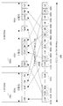
도 3은 Nant=4이고 L=3일 때 제어자원 블록 및 mini-CCE 번호 매기는 방법을 도시한 것이다. 도 2에서는 하나의 제어자원 블록 내에서 mini-CCE 번호 매기는 방법이 소개되었는데, 전 시스템 대역에 걸쳐 mini-CCE의 번호가 어떻게 매겨지는지를 도 3에서 설명하고 있다. 제어자원 블록 0(210) 내의 mini-CCE 번호는 도 2와 같고 제어자원 블록 1(211)도 동일한 방식으로 mini-CCE의 번호가 매겨진다. Mini-CCE의 번호를 일반적으로 설명하자면 제어자원 블록 K(213)에서는 7K번째 mini-CCE부터(7K+6)번째 mini-CCE까지 총 7개의 mini-CCE가 정의되며, 그 순서는 220, 221, 222, 223, 224, 225, 226과 같다. 이중 220과 224는 첫 번째 OFDM 심볼에 위치하고 221, 225는 두 번째 OFDM 심볼에 위치하며 222, 223, 226은 세 번째 OFDM 심볼에 위치한다. 특정 mini-CCE가 몇 번째 OFDM 심볼에 위치하는지는 해당 mini-CCE 번호를 7로 나눈 나머지를 보고 판단할 수 있다. 나머지가 0 또는 4이면 첫 번째 OFDM 심볼에, 나머지가 1 또는 5이면 두 번째 OFDM 심볼에, 나머지가 2, 3, 또는 6이면 세 번째 OFDM 심볼에 위치한 mini-CCE이다.FIG. 3 illustrates a control resource block and mini-CCE numbering method when N ant = 4 and L = 3. In FIG. 2, a method of mini-CCE numbering in one control resource block is introduced. FIG. 3 illustrates how mini-CCE is numbered in the entire system band. The mini-CCE number in the
시간 우선 번호 매기기는 두 mini-CCE의 번호 차이가 클수록 주파수 상에서 멀리 떨어져 있다는 특성을 이용한 것이다. 따라서 추후 매핑 규칙을 정의함에 있어서, 번호 차이가 큰 mini-CCE들로 하나의 물리 채널을 구성하면 주파수 다이버시티 이득을 최대한 얻을 수 있는 특성을 활용할 수 있다.Time-prioritized numbering takes advantage of the fact that the greater the number difference between the two mini-CCEs, the farther on frequency. Therefore, in defining the mapping rule later, by configuring one physical channel with mini-CCEs having a large number difference, a characteristic of obtaining maximum frequency diversity gain may be utilized.
도 4는 Nant=2이고 L=3일 때 제어자원 블록 0에서의 mini-CCE 번호를 도시한 것이다. 도 2와의 차이점은 2번째 OFDM 심볼에서는 RS가 정의되지 않았기 때문에 2번째 OFDM 심볼에 위치한 mini-CCE(301, 303, 306)는 4개의 RE로 구성된다는 것이다. 제어자원 블록 0(210)는 총 8개의 mini-CCE를 포함하며, 시간 우선 번호 매기기가 마찬가지로 적용되어 0번 mini-CCE부터 7번 mini-CCE까지 300, 301, 302, 303, 304, 305, 306, 307의 순서로 번호가 매겨진다.4 illustrates a mini-CCE number in the
도 5는 Nant=1이고 L=3일 때 제어자원 블록 0에서의 mini-CCE 번호를 도시한 것이다. 안테나 포트가 1개만 정의되어 RS0만 필요하지만 RS1의 자리는 비워두기 때문에 실질적으로 mini-CCE 구성에 활용 가능한 유효 RE의 위치와 개수는 안테나 포트가 2개 정의된 경우와 동일하다. 따라서 비록 안테나 포트의 수는 도 4와 차이 가 있지만 mini-CCE의 번호는 도 4에서와 동일하다. 0번 mini-CCE부터 7번 mini-CCE까지 310, 311, 312, 313, 314, 315, 316, 317의 순서로 번호가 매겨진다.5 shows a mini-CCE number in the
도 6은 Nant=1 또는 2이고 L = 3일 때 제어자원 블록 및 mini-CCE 번호 매기는 방법을 도시한 것이다. 도 4와 도 5에서 하나의 제어자원 블록 내에서 mini-CCE 번호 매기는 방법이 소개되었는데, 전 시스템 대역에 걸쳐 mini-CCE의 번호가 어떻게 매겨지는지를 도 6에서 설명하고 있다. 제어자원 블록 0(210) 내의 mini-CCE 번호는 도 4, 도 5에서와 같고 제어자원 블록 1(211)도 동일한 방식으로 mini-CCE의 번호가 매겨진다. Mini-CCE의 번호를 일반적으로 설명하자면 제어자원 블록 K(213)에서는 8K번째 mini-CCE부터(8K+7)번째 mini-CCE까지 총 8개의 mini-CCE가 정의되며, 그 순서는 330, 331, 332, 333, 334, 335, 336, 337과 같다. 이중 330과 335는 첫 번째 OFDM 심볼에 위치하고 331, 333, 336은 두 번째 OFDM 심볼에 위치하며 332, 334, 337은 세 번째 OFDM 심볼에 위치한다. 특정 mini-CCE가 몇 번째 OFDM 심볼에 위치하는지는 해당 mini-CCE 번호를 8로 나눈 나머지를 보고 판단할 수 있다. 나머지가 0 또는 5이면 첫 번째 OFDM 심볼에, 나머지가 1, 3 또는 6이면 두 번째 OFDM 심볼에, 나머지가 2, 4, 또는 7이면 세 번째 OFDM 심볼에 위치한 mini-CCE이다.FIG. 6 illustrates a control resource block and mini-CCE numbering method when N ant = 1 or 2 and L = 3. FIG. In FIG. 4 and FIG. 5, a mini-CCE numbering method in one control resource block is introduced. FIG. 6 illustrates how the mini-CCE is numbered over the entire system band. The mini-CCE numbers in the
도 7은 Nant=4이고 L=2일 때 제어자원 블록 0에서의 mini-CCE 번호를 도시한 것이다. 하나의 제어 자원 블록은 4개의 mini-CCE를 포함하게 된다. 시간 우선 번호 매기기를 적용하여 0번 mini-CCE부터 3번 mini-CCE까지 400, 401, 402, 403의 순서로 번호가 매겨진다. 모든 mini-CCE는 RS를 포함하고 있어서 6개의 RE로 구성되어 있는 것을 확인 할 수 있다.FIG. 7 illustrates a mini-CCE number in the
도 8은 Nant=4이고 L=2일 때 제어자원 블록 및 mini-CCE 번호 매기는 방법을 도시한 것이다. 도 7에서는 하나의 제어자원 블록 내에서 mini-CCE 번호 매기는 방법이 소개되었는데, 전 시스템 대역에 걸쳐 mini-CCE의 번호가 어떻게 매겨지는지를 도 8에서 설명하고 있다. 제어자원 블록 0(210) 내의 mini-CCE 번호는 도 7과 같고 제어자원 블록 1(211)도 동일한 방식으로 mini-CCE의 번호가 매겨진다. mini-CCE의 번호를 일반적으로 설명하자면 제어자원 블록 K(213)에서는 4K번째 mini-CCE부터(4K+3)번째 mini-CCE까지 총 4개의 mini-CCE가 정의되며, 그 순서는 400, 401, 402, 403과 같다. 이중 400과 402는 첫 번째 OFDM 심볼에 위치하고, 401, 403은 두 번째 OFDM 심볼에 위치한다. 특정 mini-CCE가 몇 번째 OFDM 심볼에 위치하는지는 해당 mini-CCE 번호를 4로 나눈 나머지를 보고 판단할 수 있다. 나머지가 0 또는 2이면 첫 번째 OFDM 심볼에, 나머지가 1 또는 3이면 두 번째 OFDM 심볼에 위치한 mini-CCE이다.FIG. 8 illustrates a control resource block and mini-CCE numbering method when N ant = 4 and L = 2. In FIG. 7, a mini-CCE numbering method is introduced in one control resource block. FIG. 8 illustrates how the mini-CCE is numbered in the entire system band. The mini-CCE number in the
도 9는 Nant=2이고 L=2일 때 제어자원 블록 0에서의 mini-CCE 번호를 도시한 것이다. 도 7과의 차이점은 2번째 OFDM 심볼에서는 RS가 정의되지 않았기 때문에 2번째 OFDM 심볼에 위치한 mini-CCE(501, 502, 504)는 4개의 RE로 구성된다는 것이다. 제어자원 블록 0(210)는 총 5개의 mini-CCE를 포함하며, 시간 우선 번호 매기기가 마찬가지로 적용되어 0번 mini-CCE부터 4번 mini-CCE까지 500, 501, 502, 503, 504의 순서로 번호가 매겨진다.9 illustrates a mini-CCE number in the
도 10은 Nant=1이고 L=2일 때 제어자원 블록 0에서의 mini-CCE 번호를 도시한 것이다. 안테나 포트가 1개만 정의되어 RS0만 필요하지만 RS1의 자리는 비워두기 때문에 실질적으로 mini-CCE 구성에 활용 가능한 유효 RE의 위치와 개수는 안테나 포트가 2개 정의된 경우와 동일하다. 따라서 비록 안테나 포트의 수는 도 9와 차이가 있지만 mini-CCE의 번호는 도 9에서와 동일하다. 0번 mini-CCE부터 4번 mini-CCE까지 510, 511, 512, 513, 514의 순서로 번호가 매겨진다.FIG. 10 illustrates a mini-CCE number in the
도 11은 Nant=1 또는 2이고 L=2일 때 제어자원 블록 및 mini-CCE 번호 매기는 방법을 도시한 것이다. 도 9와 도 10에서 하나의 제어자원 블록 내에서 mini-CCE 번호 매기는 방법이 소개되었는데, 전 시스템 대역에 걸쳐 mini-CCE의 번호가 어떻게 매겨지는지를 도 11에서 설명하고 있다. 제어자원 블록 0(210) 내의 mini-CCE 번호는 도 9, 도 10에서와 같고 제어자원 블록 1(211)도 동일한 방식으로 mini-CCE의 번호가 매겨진다. mini-CCE의 번호를 일반적으로 설명하자면 제어자원 블록 K(213)에서는 5K번째 mini-CCE부터(5K+4)번째 mini-CCE까지 총 5개의 mini-CCE가 정의되며, 그 순서는 530, 531, 532, 533, 534와 같다. 이중 530과 533은 첫 번째 OFDM 심볼에 위치하고 531, 532, 534는 두 번째 OFDM 심볼에 위치한다. 특정 mini-CCE가 몇 번째 OFDM 심볼에 위치하는지는 해당 mini-CCE 번호를 5로 나눈 나머지를 보고 판단할 수 있다. 나머지가 0 또는 3이면 첫 번째 OFDM 심볼에, 나머지가 1, 2 또는 4이면 두 번째 OFDM 심볼에 위치한 mini-CCE이다.FIG. 11 illustrates a control resource block and mini-CCE numbering method when N ant = 1 or 2 and L = 2. In FIG. 9 and FIG. 10, a mini-CCE numbering method in one control resource block has been introduced. FIG. 11 illustrates how the mini-CCE is numbered throughout the entire system band. The mini-CCE numbers in the
도 12는 Nant=2이고 L=1일 때 제어자원 블록 0에서의 mini-CCE 번호를 도시한 것이다. 하나의 제어 자원 블록은 2개의 mini-CCE를 포함하게 된다. 하나의 OFDM 심볼만이 제어 채널 전송에 사용되기 때문에 시간 우선 번호 매기기를 적용하더라도 단순히 주파수 축 상에서 번호를 매긴 것과 다르지 않다. 0번 mini-CCE와 1번 mini-CCE는 600, 601의 순서로 번호가 매겨진다. 모든 mini-CCE는 RS를 포함하고 있어서 6개의 RE로 구성되어 있는 것을 확인 할 수 있다.12 illustrates a mini-CCE number in the
도 13은 Nant=1이고 L=1일 때 제어자원 블록 0에서의 mini-CCE 번호를 도시한 것이다. 안테나 포트가 1개만 정의되어 RS0만 필요하지만 RS1의 자리는 비워두기 때문에 실질적으로 mini-CCE 구성에 활용 가능한 유효 RE의 위치와 개수는 안테나 포트가 2개 정의된 경우와 동일하다. 따라서 비록 안테나 포트의 수는 도 12와 차이가 있지만 mini-CCE의 번호는 도 12에서와 동일하다. 0번 mini-CCE와 1번 mini-CCE는 600, 601의 순서로 번호가 매겨진다.FIG. 13 shows a mini-CCE number in the
도 14는 L=1일 때 제어자원 블록 및 mini-CCE 번호 매기는 방법을 도시한 것이다. 도 12와 도 13에서 하나의 제어자원 블록 내에서 mini-CCE 번호 매기는 방법이 소개되었는데, 전 시스템 대역에 걸쳐 mini-CCE의 번호가 어떻게 매겨지는지를 도 14에서 설명하고 있다. 제어자원 블록 0(210) 내의 mini-CCE 번호는 도 12, 도 13에서와 같고 제어자원 블록 1(211)도 동일한 방식으로 mini-CCE의 번호가 매겨진다. Mini-CCE의 번호를 일반적으로 설명하자면 제어자원 블록 K(213)에서는 2K번째 mini-CCE부터(2K+1)번째 mini-CCE까지 총 2개의 mini-CCE가 정의되며, 그 순서는 630, 631과 같다. 하나의 OFDM 심볼만이 제어 채널 전송에 사용되기 때문에 시간 우선 번호 매기기를 적용하더라도 단순히 주파수 축 상에서 번호를 매긴 것과 다르지 않으며 모든 mini-CCE는 첫 번째 OFDM 심볼에 위치한다.FIG. 14 illustrates a control resource block and mini-CCE numbering method when L = 1. In FIG. 12 and FIG. 13, a mini-CCE numbering method in one control resource block is introduced. FIG. 14 illustrates how the mini-CCE is numbered over the entire system band. The mini-CCE numbers in the
상기 mini-CCE 번호 매기기는 다음과 같은 방법으로 기술될 수 있다. Mini-CCE는 mini-CCE를 구성하는 RE 중 첫 RE에 의해 대표된다. 즉, k는 주파수 상에서의 서브 캐리어 인덱스이고, l은 시간 상에서의 OFDM 심볼 인덱스라고 할 때, 하나의 RE는 (k,l)이라는 인덱스로 표현할 수 있다. 그리고 mini-CCE는 그 중 첫 RE의 인덱스 (k,l)에 의해 대표된다. 만약 mini-CCE를 포함하는 RB 즉, 제어 자원 블록(control resource block)이 RS로 시작한다면, mini-CCE를 대표하는 RE의 인덱스는 (k-1,l)로 바뀌어야 한다. 이 조건에서는 (k-1,l) 인덱스를 갖는 RE는 RS이다. Mini-CCE의 번호는 시간 우선 번호 매기기에 근거하는데 이 조건을 만족시키는 함수 f(k,l)에 의해 번호가 매겨지는 것으로 표현할 수 있다. 함수 f(k,l)은 mini-CCE를 대표하는 RE (k,l)을 입력으로 하는 함수로 f(k,l)의 값의 순서에 따라 해당 mini-CCE의 번호를 매기는 것이다.The mini-CCE numbering can be described in the following manner. Mini-CCE is represented by the first RE among the REs constituting the mini-CCE. That is, when k is a subcarrier index on frequency and l is an OFDM symbol index on time, one RE may be represented by an index of (k, l). The mini-CCE is represented by the index (k, l) of the first RE. If the RB including the mini-CCE, that is, the control resource block starts with RS, the index of the RE representing the mini-CCE should be changed to (k-1, l). In this condition, an RE with an index of (k-1, l) is RS. The number of Mini-CCE is based on time-prioritized numbering and can be expressed as numbered by the function f (k, l) which satisfies this condition. The function f (k, l) is a function that takes RE (k, l) representing mini-CCE as an input and numbers the corresponding mini-CCE in the order of the values of f (k, l).
이러한 함수 f(k,l)의 하나의 실시 예는 f(k,l) = k+l로 정의하는 것이다. k는 상기 예에서 살펴 보았듯이 mini-CCE가 RS를 포함하면 6의 간격으로 증가하고 RS를 포함하지 않으면 4의 간격으로 증가한다. 반면 l은 1의 간격으로 증가하게 된다. 따라서 동일한 주파수 인덱스인 k 값에서는 시간 인덱스인 l이 하나 증가하면 동일한 시간 인덱스인 l 값에서 주파수 인덱스 k를 하나 증가시킨 것이 비해 그 값이 작다는 특성을 갖는다. 따라서 시간 인덱스를 증가시킨 것이 주파수 인덱스를 증가시킨 것보다 우선해서 번호가 매겨지게 되는 특성을 가지므로 시간 우선 번호 매기기에 함수 f(k,l) = k+l를 사용하는 것이 가능하다. 이외에도 시간 우선 번호 매기기를 구현하는 다양한 함수 f(k,l)을 정의할 수 있다. 본 발명에서는 그러한 함수의 모든 실시예를 기술하는 것은 생략하기로 한다.One embodiment of such a function f (k, l) is to define f (k, l) = k + l. As shown in the above example, k increases at an interval of 6 when the mini-CCE includes RS and increases at an interval of 4 when the mini-CCE does not include RS. While l increases at intervals of one. Therefore, at the value k of the same frequency index, if the time index l is increased by one, the value is smaller than the increase of the frequency index k by one at the value l of the same time index. Therefore, it is possible to use the function f (k, l) = k + l for time-prioritized numbering because the increase of the time index has the characteristic of being numbered in preference to the increase of the frequency index. In addition, you can define various functions f (k, l) that implement time-first numbering. In the present invention, all embodiments of such a function will be omitted.
일부 mini-CCE 간에는 f(k,l)=k+l이 서로 다른 k와 l을 사용했음에도 불구하고 동일한 출력을 나타낼 수도 있다. 이 경우에는 주파수 인덱스 k가 작은 mini-CCE가 앞선 번호를 갖도록 배치하면 상기 도면에서 설명한 시간 우선 번호 매기기를 구현할 수 있다.In some mini-CCEs, f (k, l) = k + l may show the same output despite the use of different k and l. In this case, if the mini-CCE having a small frequency index k is arranged to have the preceding number, the time priority numbering described in the drawing may be implemented.
요컨대, mini-CCE를 대표하는 RE의 인덱스 (k,l)을 이용하여 mini-CCE의 번호를 매김에 있어, 시간 우선 번호 매기기 조건을 만족하는 f(k,l)이라는 함수를 도입하여 f(k,l)의 값이 작은 mini-CCE가 앞선 번호를 갖고 만약 f(k,l)의 값이 동일하면 k가 작은 mini-CCE가 앞선 번호를 갖도록 mini-CCE의 번호를 매긴다. Mini-CCE를 대표하는 RE는 mini-CCE에 포함 될 수도 있고 포함되지 않을 수도 있다. 향후 자원 매핑에서는 이렇게 매겨진 mini-CCE의 번호 순으로 4개의 변조 심볼로 구성된 변조 심볼 집합들이 배치된다.In short, in numbering mini-CCEs using the index (k, l) of RE representing mini-CCEs, a function f (k, l) that satisfies the time-priority numbering condition is introduced. If the mini-CCE with a small value of k, l) has the preceding number, and if the value of f (k, l) is the same, the mini-CCE is numbered such that the mini-CCE with a small value k has the preceding number. RE representing a Mini-CCE may or may not be included in the mini-CCE. In the future resource mapping, modulation symbol sets consisting of four modulation symbols are arranged in this ordered number of mini-CCEs.
(물리 채널의 자원 매핑)(Resource Mapping of Physical Channels)
상기 mini-CCE의 번호 매기기는 자원에 번호를 매겨서 자원 매핑이 어떻게 수행되는지를 설명하기 쉽게 하기 위한 것이다. 이번 절에서는 자원에 번호가 매겨진 이후에 물리 채널이 어떻게 자원에 매핑되는가를 설명한다. 물리 채널의 자원 매핑은 최대한 주파수 다이버시티 이득을 얻을 수 있도록 변조 심볼을 시스템 전 대역에 퍼뜨리도록 수행되어야 한다. 본 발명에서는 이러한 목적을 달성하기 위한 자원 매핑 방법으로 등간격 자원선택 방법과 지역기반 자원선택 방법을 제안한다.The mini-CCE numbering is intended to make it easier to describe how resource mapping is performed by numbering resources. This section describes how physical channels are mapped to resources after they have been numbered. Resource mapping of the physical channel should be performed to spread the modulation symbols throughout the system band so as to obtain the maximum frequency diversity gain. The present invention proposes an equally spaced resource selection method and a region-based resource selection method as a resource mapping method for achieving the above object.
도 15는 등간격 자원선택의 실시 예를 도시한 것이다. 700~710은 개별 물리 자원이다. 물리 자원의 단위는 RE가 될 수도 있고 복수 개의 인접한 RE 집합이 될 수도 있다. 여기서는 LTE 시스템에서 정의하는 제어 채널 전송에 사용되는 물리 자원이므로 단위는 mini-CCE가 된다. 그러나 물리 채널의 자원 매핑이 다른 종류의 채널에 적용된다면 물리 자원의 단위는 다르게 정의될 수 있다. 도 15의 실시 예에서는 총 11개의 mini-CCE가 가용한 경우를 예로 들고 있다. 11개의 mini-CCE 중에서 3개의 mini-CCE를 선택하여 하나의 물리 채널 전송에 사용할 것이다. 도 15는 702, 705, 708 등 3개의 mini-CCE를 선택하여 하나의 물리 채널을 구성하는 실시 예를 도시하고 있다. 선택된 첫 mini-CCE(702)는 0번 mini-CCE에서 오프셋(offset)(771)만큼 떨어진 것이고 선택된 나머지 mini-CCE(705, 708)는 일정한 간격(713)만큼 떨어져 있다. 이를 수학식으로 표현하면 하기 <수학식 1>과 같다.15 illustrates an embodiment of equal interval resource selection. 700-710 are individual physical resources. The unit of a physical resource may be an RE or a plurality of adjacent RE sets. Here, the unit is mini-CCE because it is a physical resource used for control channel transmission defined in the LTE system. However, if the resource mapping of the physical channel is applied to other types of channels, the unit of the physical resource may be defined differently. In the embodiment of FIG. 15, a case in which 11 mini-CCEs are available in total is taken as an example. Three mini-CCEs will be selected from the 11 mini-CCEs and used for one physical channel transmission. FIG. 15 illustrates an embodiment in which three mini-CCEs such as 702, 705, and 708 are selected to configure one physical channel. The first mini-CCE 702 selected is spaced by an offset 771 at
![]()
![]()
상기 <수학식 1>에서 i는 선택된 mini-CCE의 순번을 나타내며 하나의 물리 채널이 Nphy개의 mini-CCE로 구성된다면 i=0,…,Nphy-1이다. 그리고 ni는 i번째로 선택된 mini-CCE의 번호를 나타낸다. 선택된 첫 mini-CCE는 offset번째 mini-CCE가 되며 선택된 나머지 mini-CCE는 gap만큼 일정한 간격 떨어진 mini-CCE가 된다. Ntotal은 가용한 mini-CCE의 개수를 나타내며 만약 mini-CCE의 번호가 Ntotal 이상이 되면 원형 천이(cyclic shift)하도록 mod 연산을 취한다. 여기서 mod(x,y)는 x를 y로 나눈 나머지를 뜻한다. 최대한 주파수 간격을 떨어뜨려 놓기 위해서 gap을 결정하면 gap=floor(Ntotal/Nphy) 또는 gap=ceil(Ntotal/Nphy)이다. 여기서 floor(x)는 x보다 크지 않은 최대 정수를 구하는 내림함수이고 ceil(x)는 x보다 작지 않은 최소 정수를 구하는 올림함수이다. 도 15의 실시 예를 상기 <수학식 1>로 설명하면 각 파라미터는 Ntotal=11, Nphy=3, offset = 2, gap=floor(Ntotal/Nphy)=3이다.In
도 16은 지역기반 자원선택의 실시 예를 도시한 것이다. 총 11개의 mini-CCE가 가용한 상태에서 3개의 지역(zone)으로 구분한다. Zone 0(720)는 700, 701, 702 등 3개의 mini-CCE로 구성되어 있고, Zone 1(721)은 703, 704, 705 등 3개의 mini-CCE로 구성되어 있으며, Zone 2(722)는 706, 707, 708, 709, 710 등 5개의 mini-CCE로 구성되어 있다. 700, 703, 706은 각각 Zone 0(720), Zone 1(721), Zone 2(722)의 선두 mini-CCE이다. 각 지역의 선두 mini-CCE로부터 특정 offset만큼 떨어져 있는 mini-CCE가 선택되어 하나의 물리 채널을 구성한다. 도 16의 실시 예는 Zone 0(720)에서는 선두 mini-CCE 700에서 offset 0 떨어진 702를 선택하고 Zone 1(721)에서는 선두 mini-CCE 703에서 offset 1 떨어진 705를 선택하고 Zone 2(722)에서는 선두 mini-CCE 706에서 offset 2 떨어진 708을 선택하여 하나의 물리 채널을 구성하는 것을 보이고 있다. 지역기반 자원선택을 수학식으로 표현하면 하기 <수학식 2>와 같다.16 illustrates an embodiment of region-based resource selection. A total of 11 mini-CCEs are available and divided into three zones. Zone 0 (720) consists of three mini-CCEs, such as 700, 701, and 702, and Zone 1 (721) consists of three mini-CCEs, such as 703, 704, and 705, and Zone 2 (722) It consists of five mini-CCEs such as 706, 707, 708, 709, and 710. 700, 703, and 706 are the leading mini-CCEs of
![]()
![]()
상기 <수학식 2>에서 i는 선택된 mini-CCE의 순번을 나타내며 하나의 물리 채널이 Nphy개의 mini-CCE로 구성된다면 i=0,…,Nphy-1이다. Zone 별로 하나의 mini-CCE가 선택되므로 Zone의 개수는 Nphy가 되어야 한다. 상기 <수학식 2>에서 si는 Zone i의 선두 mini-CCE 번호를 나타낸다. Zone i가 zi개의 mini-CCE로 정의되었다면 s0 = 0이고 i=1,…,Nphy-1에 대해서 si = si-1+zi-1이다. ![]()
![]()
![]()
![]()
도 16의 실시 예는 Zone 0(720)과 Zone 1(772)에 대해서 zi = floor(Ntotoal/Nphy)=3을 적용하고 나머지 mini-CCE를 Zone 2(722)로 설정한 경우로, 모든 i에 대해 offseti=2를 적용하여 mini-CCE 702, 705, 708을 선택하였다.In the embodiment of FIG. 16, when z i = floor (N totoal / N phy ) = 3 is applied to
지역 기반 자원선택의 특징은 하나의 물리 채널을 구성함에 있어 물리 채널을 구성하는 데 필요한자원의 개수만큼 시스템 전 대역을 가능한 일정한 크기로 구 분하여 지역으로 설정하고 각 지역에서 물리 자원을 하나씩 선택하는 것으로, 주파수 다이버시티 이득을 보장하고 셀 별, 서브프레임 별로 자원 선택 방법을 달리하여 간섭 다이버시티 이득을 얻을 수 있게 한다. 지역 기반 자원선택 방법은 각 지역의 크기(zi)를 어떻게 설정하느냐 각 지역에서 offset(offseti)을 어떻게 설정하느냐에 따라 다양한 방법을 정의할 수 있다.The feature of region-based resource selection is that in configuring a single physical channel, the system is divided into all regions of the system as much as possible in size, and the physical resources are selected one by one. In this case, the frequency diversity gain is guaranteed and the interference diversity gain can be obtained by different resource selection methods for each cell and subframe. The region-based resource selection method can define various methods depending on how to set the size (z i ) of each region and how to set the offset (offset i ) in each region.
도 17은 지역기반 자원선택의 또 다른 실시 예를 도시한 것이다. 본 실시 예에서 각 Zone의 크기는 하기 <수학식 3>의 규칙에 의해 결정되었다.17 illustrates another embodiment of region-based resource selection. In this embodiment, the size of each zone is determined by the following rule.
즉, zi = floor((i+1)* Ntotoal/Nphy) - floor(i* Ntotoal/Nphy) for i=0,…, Nphy-2 That is, z i = floor ((i + 1) * N totoal / N phy ) -floor (i * N totoal / N phy ) for i = 0,... , N phy-2
zNphy-1 = Ntotal - floor((Nphy-1)* Ntotoal/Nphy)z Nphy-1 = N total -floor ((N phy-1 ) * N totoal / N phy )
상기 규칙에 의해서 Zone 0(730)는 700, 701, 702 등 3개의 mini-CCE, Zone 1(731)은 703, 704, 705, 706 등 4개의 mini-CCE, Zone 2(732)는 707, 708, 709, 710 등 4개의 mini-CCE로 구성된다. 모든 i에 대해 offseti=2를 적용하여 mini-CCE 702, 705, 709을 선택하여 하나의 물리 채널을 구성하였다.According to the rule, three mini-CCEs, such as 700, 701, and 702,
(제어 채널의 자원 매핑)(Resource Mapping of Control Channels)
상기의 mini-CCE 번호 매기기와 물리 채널의 자원 매핑 규칙을 기반으로 이번 절에서는 LTE 시스템에서 정의하는 하향링크 제어 채널인 PCFICH, PHICH, PDCCH의 자원 매핑 방법을 설명한다.Based on the mini-CCE numbering and the resource mapping rule of the physical channel, this section describes the resource mapping method of the downlink control channels PCFICH, PHICH, and PDCCH defined in the LTE system.
도 18은 Nant=4, L=3, LPHICH=1일 때 제어 채널 자원 매핑의 실시 예를 도시한 것이다. Nant=4, L=3 일 때 mini-CCE의 번호는 도 3과 같이 매겨진다. 도 18의 실시 예에서는 설명의 편의를 위해 제어자원 블록의 수를 6개로 가정하였으며 따라서 총 42개의 mini-CCE가 정의되어 있다. 42개의 mini-CCE를 번호순으로 1차원 재배열하면 821과 같다. PCFICH는 첫 번째 OFDM 심볼의 mini-CCE에 배치되어야 하고 LPHICH=1일 때 PHICH 역시 첫 번째 OFDM 심볼의 mini-CCE에 배치되어야 하므로 PCFICH용 mini-CCE와 PHICH용 mini-CCE를 선택하기 위해서 첫 번째 OFDM 심볼의 mini-CCE만 추려내야 한다. 823은 이와 같이 첫 번째 OFDM 심볼의 mini-CCE만 추려낸 것이다. 42개의 mini-CCE 중에서 mini-CCE 번호를 7로 나누었을 때 나머지가 0 또는 4가 되는 0번, 4번, 7번, 11번, 14번, 18번, 21번, 25번, 28번, 32번, 35번, 39번 mini-CCE인 800, 801, 802, 803, 804, 805, 806, 807, 808, 809, 810, 811 등 12개의 mini-CCE는 첫 번째 OFDM 심볼에 위치한 것들이다. 823와 같이 첫 번째 OFDM 심볼의 mini-CCE만 선택 배열한 상태에서 우선 PCFICH용 mini-CCE를 선택한다. 825는 PCFICH용 mini-CCE 4개(NPCFICH=4)를 7번 mini-CCE(802), 18번 mini-CCE(805), 28번 mini-CCE(808), 39번 mini-CCE(811)로 선택한 것이다. PCFICH mini-CCE 선택의 과정은 상기 물리 채널의 자원 매핑 규칙인 등간격 자원 선택 혹은 지역기반 자원 선 택에 따라 수행된다. PHICH를 구성하기 위해서는 첫 번째 OFDM 심볼의 mini-CCE 중에서 PCFICH용으로 사용되지 않은 mini-CCE 중에서 최대한 주파수 축 상에서 떨어져 있는 mini-CCE로 선택하여야 한다. 827은 첫 번째 OFDM 심볼의 mini-CCE 중에서 PCFICH용으로 사용되지 않은 mini-CCE를 번호순으로 배열한 것이다. PHICH용 mini-CCE 선택의 과정은 상기 물리 채널의 자원 mapping 규칙인 등간격 자원 선택 혹은 지역기반 자원 선택에 따라 수행된다. 829는 PHICH용으로 선택된 mini-CCE를 도시한 것으로 PHICH 0,1,2,3(843)은 0번 mini-CCE(800), 14번 mini-CCE(804), 32번 mini-CCE(809) 등 3개의 mini-CCE를 선택하여 구성되고(NPHICH=3) PHICH 4,5,6,7(845)은 4번 mini-CCE(801), 21번 mini-CCE(806), 35번 mini-CCE(810) 등 3개의 mini-CCE를 선택하여 구성되었다(NPHICH=3). 831은 PCFICH와 PHICH에 사용된 mini-CCE를 제외한 mini-CCE 32개를 번호순으로 재배열 한 것이다. 남은 mini-CCE(847)로부터 CCE를 구성하고 PDCCH를 매핑하게 된다.FIG. 18 illustrates an embodiment of control channel resource mapping when N ant = 4, L = 3, and L PHICH = 1. When N ant = 4 and L = 3, the mini-CCE is numbered as shown in FIG. 3. In the embodiment of FIG. 18, for convenience of explanation, the number of control resource blocks is assumed to be six, and thus, 42 mini-CCEs are defined in total. The 42 mini-CCEs in one-dimensional rearrangement in numerical order are equivalent to 821. The PCFICH should be placed in the mini-CCE of the first OFDM symbol, and when L PHICH = 1, the PHICH should also be placed in the mini-CCE of the first OFDM symbol, so the first to select the mini-CCE for the PCFICH and the mini-CCE for the PHICH is required. Only mini-CCE of the first OFDM symbol should be extracted. As such, 823 shows only the mini-CCE of the first OFDM symbol. Of the 42 mini-CCEs, when the mini-CCE number is divided by 7, 0, 4, 7, 11, 14, 18, 21, 25, 28, Twelve mini-CCEs, such as 800, 801, 802, 803, 804, 805, 806, 807, 808, 809, 810 and 811, mini-CCEs 32, 35 and 39 are located in the first OFDM symbol. . In the state where only the mini-CCE of the first OFDM symbol is selected and arranged as shown in 823, the mini-CCE for the PCFICH is selected first. The 825 uses four mini-CCEs for PCFICH (N PCFICH = 4), 7 mini-CCE (802), 18 mini-CCE (805), 28 mini-CCE (808), 39 mini-CCE (811). ). The process of PCFICH mini-CCE selection is performed according to equal interval resource selection or region based resource selection, which are resource mapping rules of the physical channel. In order to configure the PHICH, one of the mini-CCEs of the first OFDM symbol should be selected as the mini-CCE as far apart as possible from the mini-CCEs not used for the PCFICH. 827 shows a mini-CCE not used for PCFICH among the mini-CCEs of the first OFDM symbol in numerical order. The process of selecting the mini-CCE for the PHICH is performed according to the uniform interval resource selection or the region-based resource selection, which are resource mapping rules of the physical channel. 829 shows mini-CCE selected for PHICH,
도 19는 PCFICH와 PHICH를 매핑하고 남은 mini-CCE로부터 CCE 구성 및 PDCCH 자원 매핑의 실시 예를 도시한 것이다. 도 18에서 PCFICH와 PHICH용으로 선택된 mini-CCE를 제외한 나머지 mini-CCE(847)을 번호순으로 배열 한 것이 1001~1015이다. 여기서 9개의 mini-CCE(NCCE=9)를 상기 물리 채널의 자원 매핑 규칙인 등간격 자원 선택 혹은 지역기반 자원 선택에 따라 선택하여 하나의 CCE로 구성한다. CCE 0(1030), CCE 1(1031), CCE 2(1032)는 이렇게 선택된 mini-CCE들이다. 도 19의 실시 예에서는, PDCCH 0(1050)은 CCE 0(1030)와 CCE 1(1031)에 매핑되어 2개의 CCE를 사용하여 전송되고 있으며, PDCCH 1(1051)은 CCE 2(1032)에 매핑되어 1개의 CCE를 사용하여 전송되고 있다. 한편 남은 32개의 mini-CCE(847)로부터 3개의 CCE를 구성하였으므로 PDCCH에 사용되는 mini-CCE의 개수는 27개이고 5개의 mini-CCE는 어느 제어채널에도 사용되지 않는다. 5번 mini-CCE(1004), 11번 mini-CCE(1009), 25번 mini-CCE(1012) 등은 이와 같이 CCE로 선택되지 않은 mini-CCE를 나타낸다.19 illustrates an embodiment of CCE configuration and PDCCH resource mapping from mini-CCE remaining after mapping PCFICH and PHICH. In FIG. 18, the remaining
PCFICH와 PHICH를 매핑하고 남은 mini-CCE로부터 CCE 구성함에 있어, 번호 간격이 큰 mini-CCE를 선택하여 하나의 CCE를 구성하면 개별 CCE를 구성하는 mini-CCE가 주파수 축 상에서 떨어져 있을 가능성이 매우 높아지므로 주파수 다이버시티 이득을 얻을 수 있다.In mapping the PCFICH and PHICH and configuring CCEs from the remaining mini-CCEs, if a single CCE is configured by selecting a mini-CCE with a large number interval, it is very likely that the mini-CCEs constituting individual CCEs are separated on the frequency axis. Frequency diversity gain can be obtained.
도 20은 본 발명에서 제안하는 제어채널 자원 매핑 및 디매핑의 흐름도를 도시한 것이다.20 is a flowchart illustrating control channel resource mapping and demapping proposed in the present invention.
우선 901 단계에서 mini-CCE의 번호가 매겨진다. 정의된 안테나 포트의 개수 Nant와 제어 채널에 사용되는 OFDM 심볼의 개수 L에 따라 도 3, 도 6, 도 8, 도 11, 도 14에 도시된 바와 같은 규칙으로 mini-CCE의 번호가 매겨진다.First, in
다음으로 903 단계에서 모든 mini-CCE는 901 단계에서 매겨진 순서대로 1차원 재배열된다.Next, in
905 단계에서 첫 번째 OFDM 심볼에 위치하는 mini-CCE를 선택하고 번호 순으로 선택된 mini-CCE를 재배열한다.In
907 단계에서 905 단계에서 배열된 mini-CCE 중에서 NPCFICH개의 mini-CCE를 선택한다. 이 과정에서 물리 채널의 자원 매핑 규칙인 등간격 자원 선택 혹은 지역기반 자원 선택 등이 사용될 수 있다.In
909 단계에서 송신 장치의 과정으로 PCFICH 변조 심볼이 907 단계에서 선택된 PCFICH용 mini-CCE에 매핑되거나 수신 장치의 과정으로 PCFICH용 mini-CCE로부터 PCFICH 변조 심볼을 디매핑한다.In
911 단계에서 PCFICH용으로 사용된 mini-CCE를 제외한 첫 번째 OFDM 심볼의 mini-CCE를 번호 순으로 배열한다.In
913 단계에서 첫 번째 OFDM 심볼의 남은 mini-CCE로부터 NPHICH개의 mini-CCE를 선택한다. 이 과정에서 물리 채널의 자원 매핑 규칙인 등간격 자원 선택 혹은 지역기반 자원 선택 등이 사용될 수 있다. 여기서 선택된 mini-CCE는 PHICH용 mini-CCE로 바로 사용될 수도 있고 PHICH용 mini-CCE를 결정하는데 이용할 수도 있다. 만약 LPHICH=1이면 913단계에서 선택된 mini-CCE는 바로 PHICH에 매핑된다. 그러나 LPHICH=3이면 PHICH용 mini-CCE는 첫 번째 OFDM에서만 선택되는 것이 아니다. 주파수 다이버시티 이득을 보장하기 위해서 우선 첫 번째 OFDM 심볼에서 주파수 축 상 떨어져 있는 NPHICH개의 mini-CCE를 선택하고 이 중 일부 mini-CCE를 실제 PHICH용으로 사용하고 나머지 mini-CCE는 다른 OFDM 심볼에서 어떤 mini-CCE를 선택하여 PHICH용으로 사용할 것인가를 판단하는 기준으로 활용한다. 본 발명에서 제안하는 mini-CCE 번호 매기는 규칙에 따르면 첫 번째 OFDM 심볼에 위치한 mini-CCE의 번호를 하나 증가시키면 동일한 주파수 영역을 사용하는 두 번째 OFDM 심볼에 위치한 mini-CCE를 지적할 수 있고, 첫 번째 OFDM 심볼에 위치한 mini-CCE의 번호를 둘 증가시키면 동일한 주파수 영역을 사용하는 세 번째 OFDM 심볼에 위치한 mini-CCE를 지적할 수 있다. 예를 들어 도 2를 살펴보면, 첫 번째 OFDM 심볼에 위치한 4번 mini-CCE(204)의 번호를 하나 증가시킨 5번 mini-CCE(205)는 두 번째 OFDM 심볼에 위치하고, 번호를 둘 증가시킨 6번 mini-CCE(206)는 세 번째 OFDM 심볼에 위치하며 4번, 5번, 6번 mini-CCE(204, 205, 206)은 모두 중복된 주파수 영역을 차지하고 있는 것을 확인할 수 있다.In
914 단계에서 PHICH용 mini-CCE를 선택한다. PCFICH용 mini-CCE를 제외한 나머지 mini-CCE 중에서 PHICH용 mini-CCE를 선택하는데, LPHICH=1이면 913 단계에서 선택된 mini-CCE를 그대로 PCFICH용 mini-CCE로 사용하고 LPHICH≠1이면 913 단계에서 선택된 mini-CCE를 토대로 PHICH용 mini-CCE를 선택한다. 914 단계의 자세한 설명은 도 23과 도 24의 실시 예 설명에서 자세히 다룬다.In
915 단계에서 송신 장치의 과정으로 PHICH 변조 심볼이 914 단계에서 선택된 PHICH용 mini-CCE에 매핑되거나 수신 장치의 과정으로 PHICH용 mini-CCE로부터 PHICH 변조 심볼을 디매핑한다.In
917 단계에서 PCFICH용 mini-CCE와 PHICH용 mini-CCE를 제외한 나머지 mini-CCE를 번호 순으로 1차원 재배열한다.In
919 단계에서 NCCE개의 mini-CCE를 모아 CCE를 구성한다. 이 과정에서 물리 채널의 자원 매핑 규칙인 등간격 자원 선택 혹은 지역기반 자원 선택 등이 사용될 수 있다.In
마지막으로 921 단계에서 송신 장치의 과정으로 PDCCH 변조 심볼을 CCE에 매핑하거나 수신 장치의 과정으로 CCE로부터 PDCCH 변조 심볼을 디매핑한다.Finally, in
도 21은 본 발명에서 제안하는 자원 매핑이 적용된 기지국 송신기 구조를 도시한 것이다. 제어기(953)는 셀 정보, PHICH의 개수 등을 토대로 개별 제어 채널의 매핑 규칙을 결정하고 이에 따른 제어 채널 및 RS의 자원 매핑은 사상기(955)를 통해 수행된다. 사상기(955)에는 RS 생성기(931)로부터 RS, PCFICH 신호 생성기(933)로부터 PCFICH 변조 신호, PHICH 신호 생성기(935)로부터 PHICH 변조 신호, PDCCH 신호 생성기(947)로부터 PDCCH 변조 신호 등이 전달된다. PHICH 신호 생성기(935)에서는 개별 PHICH 신호 생성기(939, 947)로부터 4개의 PHICH가 모여서 CDM(943)된다. 937과 945는 각각 PHICH 0~3과 PHICH 4~7 등 4개의 PHICH 신호가 생성되는 신호 생성기이다. 한편 PDCCH 신호 생성기(947)에서는 서로 다른 단말기로 전송되는 PDCCH 신호를 생성 하는 개별 PDCCH 신호 생성기(949, 951)로 구성되어 있다. 하나의 PDCCH가 점유하는 CCE의 개수는 제어기(953)에 의해 결정된다. 제어 채널과 RS가 mapping된 신호는 PDSCH와 RS가 다중화된 신호(957)과 시간 축 상에서 다중화(959)되고 송신 처리 장치(961)을 거쳐 송신된다.21 illustrates a structure of a base station transmitter to which resource mapping proposed by the present invention is applied. The
도 22는 본 발명에서 제안하는 자원 매핑이 적용된 단말기 수신기 구조를 도시한 것이다. 송신기에서와 마찬가지로 제어기(991)는 셀 정보, PHICH의 개수 등을 토대로 개별 제어 채널의 디매핑 규칙을 결정하고 이에 따른 제어 채널 및 RS의 자원 디매핑은 역사상기(979)를 통해 수행된다. 우선 수신 신호는 수신 처리 장 치(971)를 거쳐 기저대역 신호로 변환되고 시간 축 상에서 역다중화(973)되어 PDSCH 및 PDSCH 영역의 RS와 제어 채널 및 제어 채널 영역의 RS로 분리된다. PDSCH 및 PDSCH 영역의 RS 수신 장치(953)에서 처리된 신호는 RS 역사상기(977)를 거쳐 RS를 분리해 내고 제어 채널 및 제어 채널 영역의 RS 신호는 역사상기(979)를 거쳐 RS만 분리한다(981). RS들은 채널 추정기(983)로 전달되어 채널을 추정하고 채널 추정치는 PDSCH 수신기(995), PCFICH 수신기(985), PHICH 수신기(987), PDCCH 수신기(989)로 전달되어 각각 PDSCH 신호와 PCFCH 신호, PHICH 신호, PDCCH 신호를 수신하는데 활용된다. 역사상기(979)에서 PCFICH 변조 심볼열을 구분하여 PCFICH 수신기(985)로 전달하면 해당 서브프레임에서의 제어 채널 영역의 크기 L을 복원하고 그 정보는 제어기(991)로 전달하여 역사상기(979)가 PHICH 및 PDCCH 변조 심볼열을 추출하는데 활용한다. PDSCH 역사상기(993)는 PDSCH 신호를 추출하여 PDSCH 수신기(995)로 전달하고, PDCCH 수신기(989)를 통해 복원한 데이터 채널의 할당 정보를 이용하여 제어기(991)의 통제하에서 PDSCH 수신기(995)는 데이터 채널을 복원한다.22 illustrates a structure of a terminal receiver to which resource mapping proposed by the present invention is applied. As in the transmitter, the
본 발명에서 제안하는 제어 채널의 자원 매핑 규칙이 다른 조건하에서 어떻게 적용되는지 살펴보기 위해 몇 가지 다른 실시 예를 살펴보기로 하자. 도 23과 도 24는 LPHICH가 1이 아닌 경우 PHICH의 자원 매핑이 어떻게 수행되는지를 설명하고 있다.In order to examine how the resource mapping rule of the control channel proposed in the present invention is applied under different conditions, some other embodiments will be described. 23 and 24 illustrate how resource mapping of the PHICH is performed when the L PHICH is not 1.
도 23은 Nant=1 또는 2, L=2, LPHICH=2일 때 제어채널 자원 매핑의 실시 예를 도시한 것이다. MBSFN(Multicast Broadcast Single Frequency Network) 서브프레임 은 SFN(Single Frequency Network)을 동작시키기 위한 서브프레임으로 서브프레임의 선두 2 OFDM 심볼이 제어 채널로 고정되고 나머지 OFDM 심볼은 SFN 전송으로 사용한다. LPHICH=1인 경우에는 도 18의 실시 예에서 설명한 PHICH의 자원 매핑을 적용할 수 있다. LPHICH가 1이 아니면, LPHICH=3인 것이 일반적이나, MBSFN 서브프레임에서는 특수하게 L=2이기 때문에 LPHICH=2가 된다. NPHICH=3이라면 LPHICH=2일 때 3개의 mini-CCE를 어떻게 선택할 것인가를 결정하는 규칙을 정의해야 한다. OFDM 심볼간 소비 자원 및 소비 전력의 균형을 맞추기 위해서 일부 PHICH는 첫 번째 OFDM 심볼에서 1개의 mini-CCE를 두 번째 OFDM 심볼에서 2개의 mini-CCE를 선택하여 구성하고(이하 "1+2 선택") 일부 PHICH는 첫 번째 OFDM 심볼에서 2개의 mini-CCE를 두 번째 OFDM 심볼에서 1개의 mini-CCE 선택하여 구성(이하 "2+1 선택")한다. 이렇게 PHICH용 mini-CCE를 선택하는 경우 도 18의 실시 예에서 설명한 것과 다른 추가적인 매핑 규칙이 정의되어야 한다. 이러한 추가적인 규칙은 도 20의 913, 914 단계에서 설명한 바 있다.FIG. 23 illustrates an embodiment of control channel resource mapping when N ant = 1 or 2, L = 2, and L PHICH = 2. A multicast broadcast single frequency network (MBSFN) subframe is a subframe for operating a single frequency network (SFN). The first 2 OFDM symbols of the subframe are fixed to the control channel and the remaining OFDM symbols are used for SFN transmission. When L PHICH = 1, resource mapping of the PHICH described in the embodiment of FIG. 18 may be applied. If L PHICH is not 1, L PHICH = 3 is generally used, but L PHICH = 2 since MB = 2 is specially L = 2 in the MBSFN subframe. If N PHICH = 3, then a rule that determines how to select three mini-CCEs when L PHICH = 2 should be defined. To balance the consumption of resources and power between OFDM symbols, some PHICHs are configured by selecting one mini-CCE in the first OFDM symbol and two mini-CCEs in the second OFDM symbol (hereinafter referred to as "1 + 2 selection"). Some PHICHs are configured by selecting two mini-CCEs in the first OFDM symbol and one mini-CCE in the second OFDM symbol (hereinafter, “2 + 1 selection”). When the mini-CCE for PHICH is selected as described above, an additional mapping rule different from that described in the embodiment of FIG. 18 should be defined. This additional rule has been described in
Nant=1 또는 2, L=2 일 때 mini-CCE의 번호는 도 11과 같이 매겨진다. 도 23의 실시 예에서는 설명의 편의를 위해 제어자원 블록의 수를 6개로 가정하였으며 따라서 총 30개의 mini-CCE가 정의되어 있다. 30개의 mini-CCE를 번호순으로 1차원 재배열하면 821과 같다. PCFICH는 첫 번째 OFDM 심볼의 mini-CCE에 배치되어야 하고 PHICH용 mini-CCE를 선택하기 위한 기준 mini-CCE 역시 첫 번째 OFDM 심볼의 mini-CCE에 중에서 선택되어야 하므로 PCFICH용 mini-CCE와 PHICH용 dummy mini- CCE를 선택하기 위해서 첫 번째 OFDM 심볼의 mini-CCE만 추려내야 한다. 823은 이와 같이 첫 번째 OFDM 심볼의 mini-CCE만 추려낸 것이다. 30개의 mini-CCE 중에서 mini-CCE 번호를 5로 나누었을 때 나머지가 0 또는 3이 되는 0번, 3번, 5번, 8번, 10번, 13번, 15번, 18번, 20번, 23번, 25번, 28번 mini-CCE인 850, 851, 852, 853, 854, 855, 856, 857, 858, 859, 860, 861 등 12개의 mini-CCE는 첫 번째 OFDM 심볼에 위치한 것들이다. 823와 같이 첫 번째 OFDM 심볼의 mini-CCE만 선택 배열한 상태에서 우선 PCFICH용 mini-CCE를 선택한다. 825는 PCFICH용 mini-CCE 4개(NPCFICH=4)를 5번 mini-CCE(852), 13번 mini-CCE(855), 20번 mini-CCE(858), 28번 mini-CCE(861)로 선택한 것이다. PCFICH mini-CCE 선택의 과정은 상기 물리 채널의 자원 매핑 규칙인 등간격 자원 선택 혹은 지역기반 자원 선택에 따라 수행된다. 참고로 MBSFN 서브프레임에서는 L의 값이 2로 고정되므로 PCFICH가 필요 없을 수 있다. 아직 LTE 시스템에서는 이와 같은 예외가 정의된 바 없으나 만약 MBSFN 서브프레임에 한해 PCFICH가 전송되지 않는다면 PCFICH용 mini-CCE를 선택(825)하는 것과 이와 관련한 도 20의 907, 909 단계는 생략될 수 있다.When N ant = 1 or 2 and L = 2, the mini-CCE is numbered as shown in FIG. 11. In the embodiment of FIG. 23, for convenience of explanation, the number of control resource blocks is assumed to be six, and thus a total of 30 mini-CCEs are defined. If you rearrange 30 mini-CCEs one by one in number order, it is equal to 821. The PCFICH should be placed in the mini-CCE of the first OFDM symbol and the reference mini-CCE for selecting the mini-CCE for the PHICH should also be selected from the mini-CCE of the first OFDM symbol, so the dummy for the PCFICH mini-CCE and the PHICH In order to select a mini-CCE, only the mini-CCE of the first OFDM symbol should be extracted. As such, 823 shows only the mini-CCE of the first OFDM symbol. Of the 30 mini-CCEs, when the mini-CCE number is divided by 5, the rest becomes 0 or 3, 0, 3, 5, 8, 10, 13, 15, 18, 20, Twelve mini-CCEs, such as 850, 851, 852, 853, 854, 855, 856, 857, 858, 859, 860 and 861, mini-CCEs 23, 25 and 28 are located in the first OFDM symbol. . In the state where only the mini-CCE of the first OFDM symbol is selected and arranged as shown in 823, the mini-CCE for the PCFICH is selected first. The 825 has four mini-CCEs for PCFICH (NPCFICH = 4): 5 mini-CCE (852), 13 mini-CCE (855), 20 mini-CCE (858), 28 mini-CCE (861) Will be selected. The process of PCFICH mini-CCE selection is performed according to equal interval resource selection or region based resource selection, which are resource mapping rules of the physical channel. For reference, since the value of L is fixed to 2 in the MBSFN subframe, PCFICH may not be needed. Although such an exception is not yet defined in the LTE system, if the PCFICH is not transmitted only in the MBSFN subframe, steps 907 and 909 of FIG. 20 related to selecting 825 mini-CCE for the PCFICH may be omitted.
PHICH를 구성하기 위해서는 우선 첫 번째 OFDM 심볼의 mini-CCE 중에서 PCFICH용으로 사용되지 않은 mini-CCE 중에서 최대한 주파수 축 상에서 떨어져 있는 mini-CCE로 선택하여야 한다. 이렇게 선택된 mini-CCE가 PHICH용으로 직접 사용되는 것은 아니고 PHICH용 mini-CCE를 선택하는 기준으로 활용된다. 이러한 mini-CCE를 PHICH 매핑을 위한 dummy mini-CCE라고 하자. 827은 첫 번째 OFDM 심볼의 mini-CCE 중에서 PCFICH용으로 사용되지 않은 mini-CCE를 번호순으로 배열한 것이 다. PHICH 매핑을 위한 dummy mini-CCE 선택의 과정은 상기 물리 채널의 자원 매핑 규칙인 등간격 자원 선택 혹은 지역기반 자원 선택에 따라 수행된다. 3번 mini-CCE(851), 15번 mini-CCE(856), 25번 mini-CCE(860)가 PHICH 매핑을 위한 dummy mini-CCE로 선택되었다. 이들(851, 856, 860)은 모두 첫 번째 OFDM 심볼에 위치한 것이다. 829는 PHICH용으로 선택된 mini-CCE를 도시한 것으로 PHICH 0,1,2,3(873)은 3번 mini-CCE(851), 16번 mini-CCE(863), 26번 mini-CCE(864) 등 3개의 mini-CCE를 선택하여 구성되고 PHICH 4,5,6,7(875)은 4번 mini-CCE(862), 15번 mini-CCE(856), 25번 mini-CCE(860) 등 3개의 mini-CCE를 선택하여 구성되었다(NPHICH=3).In order to configure the PHICH, one of the mini-CCEs of the first OFDM symbol should be selected as the mini-CCE as far apart as possible from the mini-CCE not used for the PCFICH. The selected mini-CCE is not directly used for PHICH but is used as a criterion for selecting a mini-CCE for PHICH. Let this mini-CCE be a dummy mini-CCE for PHICH mapping. 827 shows the mini-CCEs not used for the PCFICH among the mini-CCEs of the first OFDM symbol in numerical order. The dummy mini-CCE selection process for PHICH mapping is performed according to the equal interval resource selection or the region-based resource selection, which are resource mapping rules of the physical channel. 3 mini-CCE (851), 15 mini-CCE (856), 25 mini-CCE (860) was selected as a dummy mini-CCE for PHICH mapping. These 851, 856, 860 are all located in the first OFDM symbol. 829 shows mini-CCE selected for PHICH,
PHICH용 mini-CCE를 선택하는 과정을 자세히 살펴보면 PHICH 매핑을 위한 dummy mini-CCE 중 첫 번째 OFDM 심볼에 위치한 3번 mini-CCE(851)을 PHICH 0,1,2,3(873)을 매핑하는 데 사용하였다. PHICH 0,1,2,3(873)는 "1+2 선택"으로 구성된다고 가정하면 나머지 두 mini-CCE는 두 번째 OFDM 심볼에서 선택하여야 한다. 따라서 PHICH mapping을 위한 나머지 dummy mini-CCE인 15번 mini-CCE(856)과 25번 mini-CCE(860)의 번호를 하나 증가시킨 16번 mini-CCE(863), 26번 mini-CCE(864)를 PHICH 0,1,2,3(873)을 매핑하는 데 사용하였다. 앞서 설명한 바와 같이 본 발명에서 제안하는 mini-CCE 번호 매기는 규칙에 따르면 mini-CCE의 번호를 하나 증가 시키면 다음 OFDM 심볼에서 동일한 주파수 영역에 위치한 mini-CCE를 지적할 수 있다. 이미 첫 번째 OFDM 심볼에서 선택한 PHICH 용 dummy mini-CCE는 주파수 축 상에서 가능한 멀리 떨어진 것으로 선택하였기 때문에 mini-CCE의 번호를 증가시켜 선택한 두 번째 OFDM 심볼의 mini-CCE 역시 주파수 축 상에서 멀리 떨어진 것을 보장한다. 따라서 주파수 다이버시티 이득을 동일하게 얻을 수 있다. 한편 PHICH 매핑을 위한 dummy mini-CCE 중 첫 번째 OFDM 심볼에 위치한 15번 mini-CCE(856)과 25번 mini-CCE(860)을 PHICH 4,5,6,7(875)을 매핑하는 데 사용하였다. PHICH 0,1,2,3(873)는 "1+2 선택"으로 구성하였으므로 PHICH 4,5,6,7(875)은 "2+1 선택"으로 구성한 것이다. 이는 OFDM 심볼간 소비 자원 및 소비 전력의 균형을 맞추기 위함이다. 2개의 mini-CCE가 첫 번째 OFDM 심볼에서 선택되었으므로 1개의 mini-CCE는 두 번째 OFDM 심볼에서 선택한다. 이를 위해 PHICH 0,1,2,3(873)에 사용된 3번 mini-CCE(851)의 번호를 하나 증가시킨 4번 mini-CCE(862)를 PHICH 4,5,6,7(875)용 mini-CCE로 선택한다. 이에 따라 PHICH 0,1,2,3(873)는 3번 mini-CCE(851), 16번 mini-CCE(863), 26번 mini-CCE(864)에 매핑되고 PHICH 4,5,6,7(875)는 4번 mini-CCE(862), 15번 mini-CCE(856)과 25번 mini-CCE(860)에 매핑된다.Looking at the process of selecting a mini-CCE for PHICH in detail mapping the
정리하자면 PHICH 매핑을 위한 dummy mini-CCE가 #A, #B, #C 선택되었다면 PHICH a~a+3은 mini-CCE #A, #(B+1), #(C+1)에 매핑하고 PHICH a+4~a+7은 mini-CCE #(A+1), #B, #C에 매핑한다. 이렇게 하면 PHICH a~a+3은 "1+2 선택"으로 구성되고 PHICH a+4~a+7은 "2+1" 선택으로 구성된다. 추가적인 PHICH가 필요할 경우에는 또 다른 dummy mini-CCE를 선택하여 동일한 과정을 반복하여 PHICH 매핑을 위한 mini-CCE를 선택한다.In summary, if dummy mini-CCE for PHICH mapping is selected #A, #B, #C, PHICH a ~ a + 3 maps to mini-CCE #A, # (B + 1), # (C + 1) PHICH a + 4 ~ a + 7 maps to mini-CCE # (A + 1), #B, #C. In this way, PHICH a ~ a + 3 consists of "1 + 2 selection" and PHICH a + 4 ~ a + 7 consists of "2 + 1" selection. If additional PHICH is needed, another dummy mini-CCE is selected and the same process is repeated to select mini-CCE for PHICH mapping.
다른 방법으로 PHICH 매핑을 위한 dummy mini-CCE가 #A, #B, #C 선택되었다 면 PHICH a~a+3은 mini-CCE #A, #(B+1), #C에 mapping하고 PHICH a+4~a+7은 mini-CCE #(A+1), #B, #(C+1)에 매핑하는 방법이 있다. 이렇게 하면 PHICH a~a+3은 "2+1 선택"으로 구성되고 PHICH a+4~a+7은 "1+2" 선택으로 구성된다.Alternatively, if dummy mini-CCE for PHICH mapping is selected #A, #B, #C, PHICH a ~ a + 3 maps to mini-CCE #A, # (B + 1), #C and PHICH a There are ways to map + 4 ~ a + 7 to mini-CCE # (A + 1), #B, # (C + 1). In this way, PHICH a ~ a + 3 consists of "2 + 1 selection" and PHICH a + 4 ~ a + 7 consists of "1 + 2" selection.
831은 PCFICH와 PHICH에 사용된 mini-CCE를 제외한 mini-CCE 20개를 번호순으로 재배열 한 것이다. 남은 mini-CCE(877)로부터 CCE를 구성하고 PDCCH를 매핑하게 된다.The 831 is a rearrangement of 20 mini-CCEs in numerical order except the mini-CCEs used in the PCFICH and PHICH. The CCE is configured from the remaining
도 24는 Nant=4, L=3, LPHICH=3일 때 제어채널 자원 매핑의 실시 예를 도시한 것이다. LPHICH=3이고 NPHICH=3이라면 각 OFDM 심볼에서 하나의 mini-CCE를 선택하여 PHICH를 구성해야 한다. 그리고 서로 다른 OFDM 심볼에서 선택된 mini-CCE라 하더라도 최대한 주파수 축상에서 멀리 떨어지도록 선택되어야 주파수 다이버시티 이득을 얻을 수 있다.FIG. 24 illustrates an embodiment of control channel resource mapping when N ant = 4, L = 3, and L PHICH = 3. If L PHICH = 3 and N PHICH = 3, one mini-CCE should be selected from each OFDM symbol to configure a PHICH. In addition, even mini-CCEs selected from different OFDM symbols should be selected as far away from the frequency axis as possible to obtain frequency diversity gain.
Nant=4, L=3 일 때 mini-CCE의 번호는 도 3과 같이 매겨진다. 도 24의 실시 예에서는 설명의 편의를 위해 제어자원 블록의 수를 6개로 가정하였으며 따라서 총 42개의 mini-CCE가 정의되어 있다. 42개의 mini-CCE를 번호순으로 1차원 재배열하면 821과 같다. PCFICH는 첫 번째 OFDM 심볼의 mini-CCE에 배치되어야 하고 LPHICH=1일 때 PHICH 역시 첫 번째 OFDM 심볼의 mini-CCE에 배치되어야 하므로 PCFICH용 mini-CCE와 PHICH용 mini-CCE를 선택하기 위해서 첫 번째 OFDM 심볼의 mini-CCE만 추려내야 한다. 823은 이와 같이 첫 번째 OFDM 심볼의 mini-CCE만 추려낸 것이다. 42개의 mini-CCE 중에서 mini-CCE 번호를 7로 나누었을 때 나머지가 0 또는 4가 되 는 0번, 4번, 7번, 11번, 14번, 18번, 21번, 25번, 28번, 32번, 35번, 39번 mini-CCE인 880, 881, 882, 883, 884, 885, 886, 887, 888, 889, 890, 891 등 12개의 mini-CCE는 첫 번째 OFDM 심볼에 위치한 것들이다. 823와 같이 첫 번째 OFDM 심볼의 mini-CCE만 선택 배열한 상태에서 우선 PCFICH용 mini-CCE를 선택한다. 825는 PCFICH용 mini-CCE 4개(NPCFICH=4)를 7번 mini-CCE(882), 18번 mini-CCE(805), 28번 mini-CCE(888), 39번 mini-CCE(891)로 선택한 것이다. PCFICH mini-CCE 선택의 과정은 상기 물리 채널의 자원 매핑 규칙인 등간격 자원 선택 혹은 지역기반 자원 선택에 따라 수행된다. 참고로 LPHICH의 값이 3으로 고정되므로 어쩔 수 없이 선두 3개의 OFDM 심볼은 제어 채널 전송에 사용할 수 밖에 없으므로 CCFI 정보는 무의미하며 PCFICH가 필요 없을 수 있다. 아직 LTE 시스템에서는 이와 같은 예외가 정의된 바 없으나 만약 LPHICH=3에 한해 PCFICH가 전송되지 않는다면 PCFICH용 mini-CCE를 선택(825)하는 것과 이와 관련한 도 20의 907, 909 단계는 생략될 수 있다.When N ant = 4 and L = 3, the mini-CCE is numbered as shown in FIG. 3. In the embodiment of FIG. 24, for convenience of explanation, the number of control resource blocks is assumed to be six, and thus 42 mini-CCEs are defined in total. The 42 mini-CCEs in one-dimensional rearrangement in numerical order are equivalent to 821. The PCFICH should be placed in the mini-CCE of the first OFDM symbol, and when L PHICH = 1, the PHICH should also be placed in the mini-CCE of the first OFDM symbol, so the first to select the mini-CCE for the PCFICH and the mini-CCE for the PHICH is required. Only mini-CCE of the first OFDM symbol should be extracted. As such, 823 shows only the mini-CCE of the first OFDM symbol. Of the 42 mini-CCEs, the mini-CCE number divided by 7 results in 0, 4, 7, 11, 14, 18, 21, 25, 28, where the remainder becomes 0 or 4. 12 mini-CCEs, such as 880, 881, 882, 883, 884, 885, 886, 887, 888, 889, 890, 891, mini-CCEs 32, 35 and 39, are located in the first OFDM symbol. to be. In the state where only the mini-CCE of the first OFDM symbol is selected and arranged as shown in 823, the mini-CCE for the PCFICH is selected first. The 825 has four mini-CCEs for PCFICH (NPCFICH = 4): 7 mini-CCE (882), 18 mini-CCE (805), 28 mini-CCE (888), 39 mini-CCE (891) Will be selected. The process of PCFICH mini-CCE selection is performed according to equal interval resource selection or region based resource selection, which are resource mapping rules of the physical channel. For reference, since the value of L PHICH is fixed to 3, since the first three OFDM symbols are inevitably used for transmission of the control channel, CCFI information is meaningless and PCFICH may not be needed. Although such an exception has not been defined in the LTE system, but if PCFICH is not transmitted only for L PHICH = 3,
PHICH를 구성하기 위해서는 첫 번째 OFDM 심볼의 mini-CCE 중에서 PCFICH용으로 사용되지 않은 mini-CCE 중에서 최대한 주파수 축 상에서 떨어져 있는 mini-CCE를 PHICH용 dummy mini-CCE로 선택하여야 한다. 827은 첫 번째 OFDM 심볼의 mini-CCE 중에서 PCFICH용으로 사용되지 않은 mini-CCE를 번호순으로 배열한 것이다. PHICH 매핑을 위한 dummy mini-CCE 선택의 과정은 상기 물리 채널의 자원 매핑 규칙인 등간격 자원 선택 혹은 지역기반 자원 선택에 따라 수행된다. 4번 mini-CCE(881), 21번 mini-CCE(886), 35번 mini-CCE(890)가 PHICH 매핑을 위한 dummy mini-CCE로 선택되었다. 이들(881, 886, 890)은 모두 첫 번째 OFDM 심볼에 위치한 것이다. 829는 PHICH용으로 선택된 mini-CCE를 도시한 것으로 PHICH 0,1,2,3(1103)은 4번 mini-CCE(881), 22번 mini-CCE(893), 37번 mini-CCE(894) 등 3개의 mini-CCE를 선택하여 구성되고 PHICH 4,5,6,7(1105)은 5번 mini-CCE(895), 23번 mini-CCE(896), 35번 mini-CCE(890) 등 3개의 mini-CCE를 선택하여 구성되었다.In order to configure the PHICH, the mini-CCE that is separated from the mini-CCE not used for the PCFICH among the mini-CCEs of the first OFDM symbol as far as possible on the frequency axis is selected as the dummy mini-CCE for the PHICH. 827 shows a mini-CCE not used for PCFICH among the mini-CCEs of the first OFDM symbol in numerical order. The dummy mini-CCE selection process for PHICH mapping is performed according to the equal interval resource selection or the region-based resource selection, which are resource mapping rules of the physical channel. 4 mini-CCE (881), 21 mini-CCE (886), 35 mini-CCE (890) was selected as a dummy mini-CCE for PHICH mapping. These 881, 886, 890 are all located in the first OFDM symbol. 829 shows mini-CCE selected for PHICH,
PHICH용 mini-CCE를 선택하는 과정을 자세히 살펴보면 PHICH 매핑을 위한 dummy mini-CCE 중 첫 번째 OFDM 심볼에 위치한 4번 mini-CCE(881)을 PHICH 0,1,2,3(1103)을 매핑하는 데 사용하였다. 두 번째 OFDM 심볼에서 mini-CCE를 하나 선택하기 위해 PHICH 매핑을 위한 dummy mini-CCE인 21번 mini-CCE(886)의 번호를 하나 증가시킨 22번 mini-CCE(893)를 PHICH 0,1,2,3(1103)을 매핑하는 데 사용하였다. 그리고 세 번째 OFDM 심볼에서 mini-CCE를 하나 선택하기 위해 PHICH 매핑을 위한 dummy mini-CCE인 35번 mini-CCE(890)의 번호를 둘 증가시킨 37번 mini-CCE(894)를 PHICH 0,1,2,3(1103)을 mapping하는 데 사용하였다. 따라서 PHICH 0,1,2,3(1103)은 4번 mini-CCE(881), 22번 mini-CCE(893), 37번 mini-CCE(894) 등 3개의 mini-CCE를 선택하여 구성된다. 한편 PHICH 매핑을 위한 dummy mini-CCE 중 첫 번째 OFDM 심볼에 위치한 35번 mini-CCE(890)을 PHICH 4,5,6,7(1105)을 mapping하는 데 사용하였다. 두 번째 OFDM 심볼에서 mini-CCE를 하나 선택하기 위해 PHICH mapping을 위한 dummy mini-CCE인 4번 mini-CCE(881)의 번호를 하나 증가시킨 5번 mini-CCE(895)를 PHICH 4,5,6,7(1105)을 매핑하는 데 사용하였다. 그리고 세 번째 OFDM 심볼에서 mini-CCE를 하나 선택하기 위해 PHICH 매핑을 위한 dummy mini-CCE 인 21번 mini-CCE(886)의 번호를 둘 증가시킨 23번 mini-CCE(896)를 PHICH 4,5,6,7(1105)을 매핑하는 데 사용하였다. 따라서 PHICH 4,5,6,7(1105)은 5번 mini-CCE(895), 23번 mini-CCE(896), 35번 mini-CCE(890) 등 3개의 mini-CCE를 선택하여 구성된다.Looking at the process of selecting a mini-CCE for PHICH in detail mapping the
정리하자면 PHICH 매핑을 위한 dummy mini-CCE가 #A, #B, #C 선택되었다면 PHICH a~a+3은 mini-CCE #A, #(B+1), #(C+2)에 mapping하고 PHICH a+4~a+7은 mini-CCE #(A+1), #(B+2), #C에 mapping하며 PHICH a+8~a+11은 mini-CCE #(A+2), #B, E(C+1)에 매핑한다. 이렇게 함으로써 각 OFDM 심볼별로 하나의 mini-CCE를 선택하되 주파수 상 거리가 멀리 떨어진 것을 선택할 수 있다. 추가적인 PHICH가 필요할 경우에는 또 다른 dummy mini-CCE를 선택하여 동일한 과정을 반복하여 PHICH mapping을 위한 mini-CCE를 선택한다.To sum up, if dummy mini-CCE for PHICH mapping is selected #A, #B, #C, PHICH a ~ a + 3 maps to mini-CCE #A, # (B + 1), # (C + 2) PHICH a + 4 ~ a + 7 maps to mini-CCE # (A + 1), # (B + 2), #C. PHICH a + 8 ~ a + 11 maps to mini-CCE # (A + 2), Maps to #B, E (C + 1). By doing so, one mini-CCE may be selected for each OFDM symbol, but a far distance in frequency may be selected. If additional PHICH is needed, select another dummy mini-CCE and repeat the same process to select mini-CCE for PHICH mapping.
831은 PCFICH와 PHICH에 사용된 mini-CCE를 제외한 mini-CCE 32개를 번호순으로 재배열 한 것이다. 남은 mini-CCE(1107)로부터 CCE를 구성하고 PDCCH를 매핑하게 된다.The 831 is a rearrangement of the 32 mini-CCEs in numerical order except the mini-CCEs used in the PCFICH and PHICH. The CCE is configured from the remaining
임의의 LPHICH에 따라 PHICH 매핑 방법을 수학식으로 표현하는 것은 구현을 용이하게 하는데에 도움이 된다. 그러면 PHICH 매핑 방법을 수학식으로 표현하는 방법에 대하여 살펴보기로 한다.The mathematical expression of the PHICH mapping method according to any L PHICH helps to facilitate the implementation. Next, a method of expressing the PHICH mapping method by an equation will be described.
우선 PHICH 그룹을 정의해야 한다. 앞서 도면을 통해 설명한 바와 같이 복수 개의 PHICH는 CDM되어 전송된다. 이와 같이 동일한 물리 자원에 CDM되는 PHICH의 집합을 PHICH 그룹이라고 정의한다. 4개의 PHICH가 CDM되어 전송된다면, PHICH a, PHICH a+1, PHICH a+2, PHICH a+3은 하나의 PHICH 그룹을 구성한다. 또한 실수 성분과 복소수 성분에 서로 다른 PHICH를 전송하는 I/Q 다중화를 적용한다면 8개의 PHICH가 CDM되며 PHICH a ~ PHICH a+7은 하나의 PHICH 그룹을 구성한다. PHICH 그룹 인덱스 g는 주어진 PHICH가 어느 PHICH 그룹에서 CDM되어 있는지를 나타내는 값이다. PHICH 인덱스를 p라고 하면 PHICH 그룹 인덱스는 하기 <수학식 4>와 같이 계산할 수 있다.First, PHICH group should be defined. As described above, the plurality of PHICHs are transmitted through CDM. In this way, a set of PHICHs CDMed to the same physical resource is defined as a PHICH group. If four PHICHs are transmitted by CDM, PHICH a, PHICH a + 1, PHICH a + 2, and PHICH a + 3 constitute one PHICH group. In addition, if I / Q multiplexing that transmits different PHICHs to real and complex components is applied, eight PHICHs are CDM, and PHICH a to PHICH a + 7 form one PHICH group. The PHICH group index g is a value indicating in which PHICH group a given PHICH is CDM. If the PHICH index is p, the PHICH group index may be calculated as shown in
여기서 PHICH_GROUP_SIZE는 하나의 PHICH 그룹에 몇 개의 PHICH가 CDM 되는가를 나타내는 값으로 I/Q 다중화를 적용했을 경우 8이고 그렇지 않을 경우 4이다.Here, PHICH_GROUP_SIZE is a value indicating how many PHICHs are CDMs in one PHICH group, which is 8 when I / Q multiplexing is applied and 4 otherwise.
CDM된 PHICH 그룹을 전송하기 위해서는 하나의 mini-CCE 만큼의 물리 자원으로 충분하다. 그러나 주파수 다이버시티 이득을 얻기 위해서 주파수 축상에서 NPHICH번 반복하여 전송한다. 즉 NPHICH개의 mini-CCE가 하나의 PHICH 그룹을 전송하는데 사용된다. NPHICH=3이라고 하면 3개의 mini-CCE를 이용하여 반복 전송하게 되는 것이다. 하나의 PHICH 그룹을 전송하는 mini-CCE 각각에 번호를 매겨서 이를 반복 인덱스라고 정의하자. 반복 인덱스 r은 0, 1, …, NPHICH-1의 값을 가진다.In order to transmit the CDM PHICH group, a physical resource of one mini-CCE is sufficient. However, in order to obtain frequency diversity gain, it transmits repeatedly N PHICH times on the frequency axis. That is, N PHICH mini-CCEs are used to transmit one PHICH group. If N PHICH = 3, it will be repeatedly transmitted using three mini-CCEs. Number each mini-CCE transmitting one PHICH group and define it as a recursive index. Repetition index r is 0, 1,... , N PHICH -1.
PHICH 그룹 g에 속한 PHICH의 매핑을 위해 dummy mini-CCE로 첫 번째 OFDM 심볼에 위치한 #A0(g,0), #A0(g,1), …, #A0(g,NPHICH-1)가 선택되었다면 LPHICH, PHICH 그룹 인덱스 g, 반복 인덱스 r에 따라 실제 PHICH가 매핑되는 mini-CCE는 #A(g,0), #A(g,1), …, #A(g,NPHICH-1)가 되고 A(g,r)는 하기 <수학식 5>와 같이 계산된다.#A 0 (g, 0), #A 0 (g, 1),… located in the first OFDM symbol with dummy mini-CCE for mapping of PHICH belonging to PHICH group g. If #A 0 (g, N PHICH -1) is selected, the mini-CCE to which the actual PHICH is mapped according to L PHICH , PHICH group index g, and repetition index r is #A (g, 0), #A (g, One), … , #A (g, N PHICH- 1) and A (g, r) is calculated as in
상기 방식을 이용하면 임의의 LPHICH에 따라 PHICH 매핑 방법을 수학식으로 표현할 수 있다. 예를 들어 LPHICH=1이라면 #A0(g,0), #A0(g,1),..., #A0(g,NPHICH-1)가 그대로 PHICH 매핑용 mini-CCE가 된다. 이때, mod(g+r,LPHICH)은 g와 r이 어떠한 값을 가지더라도 0이 되므로 원하는 동작을 수행하게 된다. 또한 LPHICH=2 또는 3일 경우 각각 도 23과 도 24의 동작을 동일하게 수행한다.Using the above scheme, the PHICH mapping method may be expressed by an equation according to any L PHICH . For example, if L PHICH = 1, #A 0 (g, 0), #A 0 (g, 1), ..., #A 0 (g, N PHICH -1) are the same as mini-CCE for PHICH mapping. do. At this time, mod (g + r, L PHICH ) becomes 0 because g and r have any value, thereby performing a desired operation. In addition, when L PHICH = 2 or 3, the operations of FIGS. 23 and 24 are performed in the same manner.
도 1은 LTE 시스템에서 subframe 구조를 도시한 도면,1 is a diagram illustrating a subframe structure in an LTE system,
도 2는 Nant = 4이고 L = 3일 때 제어자원 블록 0에서의 mini-CCE 번호의 할당을 도시한 도면,2 is a diagram illustrating the allocation of a mini-CCE number in the
도 3는 Nant = 4이고 L = 3일 때 제어자원 블록 및 mini-CCE 번호의 할당을 도시한 도면,3 is a diagram illustrating allocation of a control resource block and a mini-CCE number when Nant = 4 and L = 3;
도 4는 Nant = 2이고 L = 3일 때 제어자원 블록 0에서의 mini-CCE 번호의 할당을 도시한 도면,4 is a diagram illustrating the allocation of a mini-CCE number in the
도 5는 Nant = 1이고 L = 3일 때 제어자원 블록 0에서의 mini-CCE 번호의 할당을 도시한 도면,5 is a diagram illustrating the allocation of a mini-CCE number in the
도 6은 Nant = 1 또는 2이고 L = 3일 때 제어자원 블록 및 mini-CCE 번호의 할당을 도시한 도면,6 is a diagram illustrating allocation of a control resource block and a mini-CCE number when Nant = 1 or 2 and L = 3;
도 7은 Nant = 4이고 L = 2일 때 제어자원 블록 0에서의 mini-CCE 번호의 할당을 도시한 도면,7 is a diagram illustrating the allocation of a mini-CCE number in the
도 8은 Nant = 4이고 L = 2일 때 제어자원 블록 및 mini-CCE 번호의 할당을 도시한 도면,8 is a diagram illustrating allocation of a control resource block and a mini-CCE number when Nant = 4 and L = 2;
도 9는 Nant = 2이고 L = 2일 때 제어자원 블록 0에서의 mini-CCE 번호의 할당을 도시한 도면,9 is a diagram illustrating the allocation of a mini-CCE number in the
도 10은 Nant = 1이고 L = 2일 때 제어자원 블록 0에서의 mini-CCE 번호의 할당을 도시한 도면,FIG. 10 is a diagram illustrating allocation of mini-CCE numbers in
도 11은 Nant = 1 또는 2이고 L = 2일 때 제어자원 블록 및 mini-CCE 번호의 할당을 도시한 도면,11 is a diagram illustrating allocation of a control resource block and a mini-CCE number when Nant = 1 or 2 and L = 2;
도 12는 Nant = 2이고 L = 1일 때 제어자원 블록 0에서의 mini-CCE 번호의 할당을 도시한 도면,12 is a diagram illustrating the allocation of a mini-CCE number in the
도 13은 Nant = 1이고 L = 1일 때 제어자원 블록 0에서의 mini-CCE 번호의 할당을 도시한 도면,FIG. 13 is a diagram illustrating allocation of mini-CCE numbers in
도 14는 L = 1일 때 제어자원 블록 및 mini-CCE 번호의 할당을 도시한 도면,14 is a diagram illustrating allocation of a control resource block and a mini-CCE number when L = 1;
도 15는 등간격 자원선택의 실시 예를 설명하기 위한 도면,15 is a view for explaining an embodiment of equal interval resource selection;
도 16은 지역기반 자원선택의 제 1 실시 예를 설명하기 위한 도면,16 is a view for explaining a first embodiment of region-based resource selection;
도 17은 지역기반 자원선택의 제 2 실시 예를 설명하기 위한 도면,17 is a view for explaining a second embodiment of region-based resource selection;
도 18은 Nant = 4, L = 3, LPHICH = 1일 때 제어채널 자원 mapping의 실시 예를 설명하기 위한 도면,18 is a diagram for explaining an embodiment of control channel resource mapping when Nant = 4, L = 3, and LPHICH = 1;
도 19는 mini-CCE로부터 CCE 구성 및 PDCCH 자원 mapping의 실시 예를 설명하기 위한 도면,19 is a view for explaining an embodiment of CCE configuration and PDCCH resource mapping from mini-CCE;
도 20은 제어채널 자원 매핑 및 디매핑을 수행하기 위한 이동 단말의 흐름도,20 is a flowchart of a mobile terminal for performing control channel resource mapping and demapping;
도 21은 본 발명에서 제안하는 자원 매핑이 적용된 송신기 장치의 구성도,21 is a configuration diagram of a transmitter device to which resource mapping proposed in the present invention is applied;
도 22는 본 발명에서 제안하는 자원 매핑이 적용된 수신기 장치의 구성도,22 is a configuration diagram of a receiver device to which resource mapping proposed in the present invention is applied;
도 23은 Nant = 1 또는 2, L = 2, LPHICH = 2일 때 제어채널 자원 mapping의 실시 예를 설명하기 위한 도면,FIG. 23 is a diagram for explaining an embodiment of control channel resource mapping when Nant = 1 or 2, L = 2, and LPHICH = 2; FIG.
도 24는 Nant = 4, L = 3, LPHICH = 3일 때 제어채널 자원 mapping의 실시 예를 설명하기 위한 도면.FIG. 24 illustrates an embodiment of control channel resource mapping when Nant = 4, L = 3, and LPHICH = 3; FIG.
Claims (10)
Priority Applications (28)
| Application Number | Priority Date | Filing Date | Title |
|---|---|---|---|
| KR1020080000400A KR101376233B1 (en) | 2007-10-02 | 2008-01-02 | Apparatus and method for allocating control channel in a frequency division multiple access system |
| JP2010527892A JP5676261B2 (en) | 2007-10-02 | 2008-10-02 | Resource allocation method and apparatus for control channel in mobile communication system using orthogonal frequency division multiplexing |
| CA2701256A CA2701256C (en) | 2007-10-02 | 2008-10-02 | Method and apparatus for allocating resources of a control channel in a mobile communication system using orthogonal frequency division multiplexing |
| EP08017395.8A EP2045952B1 (en) | 2007-10-02 | 2008-10-02 | Allocation of resources to a control channel in a multicarrier mobile communication system |
| CN201410488058.5A CN104253682B (en) | 2007-10-02 | 2008-10-02 | The method and apparatus transmitted in mobile communication system and receive control channel |
| BRPI0817494-6A BRPI0817494B1 (en) | 2007-10-02 | 2008-10-02 | METHOD AND APPARATUS FOR ALLOCATING RESOURCES OF A DOWNLINK CONTROL CHANNEL AND APPARATUS FOR RECEIVING A DOWNLINK CONTROL CHANNEL |
| US12/244,445 US8208438B2 (en) | 2007-10-02 | 2008-10-02 | Method and apparatus for allocating resources of a control channel in a mobile communication system using orthogonal frequency division multiplexing |
| CN201310062509.4A CN103152152B (en) | 2007-10-02 | 2008-10-02 | The method and apparatus that in mobile communication system, distribution controls the resource of channel |
| AU2008307876A AU2008307876B2 (en) | 2007-10-02 | 2008-10-02 | Method and apparatus for allocating resources of a control channel in a mobile communication system using Orthogonal Frequency Division Multiplexing |
| MYPI2010001228A MY155991A (en) | 2007-10-02 | 2008-10-02 | Method and apparatus for allocating resources of a control channel in a mobile communication system using orthogonal frequency division multiplexing |
| RU2011150472/07A RU2583045C2 (en) | 2007-10-02 | 2008-10-02 | Method and device for allocating control channel resources in mobile communication system using orthogonal frequency division multiplexing |
| CA2925851A CA2925851C (en) | 2007-10-02 | 2008-10-02 | Method and apparatus for allocating resources of a control channel in a mobile communication system using orthogonal frequency division multiplexing |
| CN200880110082.8A CN101816158B (en) | 2007-10-02 | 2008-10-02 | Method and device for allocating resources of control channel in mobile communication system using orthogonal frequency division multiplexing |
| PCT/KR2008/005833 WO2009045076A2 (en) | 2007-10-02 | 2008-10-02 | Method and apparatus for allocating resources of a control channel in a mobile communication system using orthogonal frequency division multiplexing |
| RU2010112725/07A RU2447600C2 (en) | 2007-10-02 | 2008-10-02 | Method and device for control channel resources allocation in mobile communication system using orthogonal frequency division multiplexing |
| DE202008018273U DE202008018273U1 (en) | 2007-10-02 | 2008-10-02 | Assignment of Resources to a Control Channel in a Multi-Carrier Mobile Communication System |
| DE202008018255U DE202008018255U1 (en) | 2007-10-02 | 2008-10-02 | Assignment of resources to a control channel in a multi-carrier mobile communication system |
| MX2010003675A MX2010003675A (en) | 2007-10-02 | 2008-10-02 | Method and apparatus for allocating resources of a control channel in a mobile communication system using orthogonal frequency division multiplexing. |
| ZA2010/02429A ZA201002429B (en) | 2007-10-02 | 2010-04-07 | Method and apparatus for allocating resources of a control channel in a mobile communication system using orthogonal frequency division multiplexing |
| US13/532,226 US8953552B2 (en) | 2007-10-02 | 2012-06-25 | Method and apparatus for allocating resources of a control channel in a mobile communication system using orthogonal frequency division multiplexing |
| JP2013253204A JP5784692B2 (en) | 2007-10-02 | 2013-12-06 | Resource allocation method and apparatus for control channel in mobile communication system using orthogonal frequency division multiplexing |
| US14/601,795 US9167569B2 (en) | 2007-10-02 | 2015-01-21 | Method and apparatus for allocating resources of a control channel in a mobile communication system using orthogonal frequency division multiplexing |
| US14/624,213 US9277544B2 (en) | 2007-10-02 | 2015-02-17 | Method and apparatus for allocating resources of a control channel in a mobile communication system using orthogonal frequency division multiplexing |
| US14/624,199 US9282547B2 (en) | 2007-10-02 | 2015-02-17 | Method and apparatus for allocating resources of a control channel in a mobile communication system using orthogonal frequency division multiplexing |
| US14/624,206 US9380565B2 (en) | 2007-10-02 | 2015-02-17 | Method and apparatus for allocating resources of a control channel in a mobile communication system using orthogonal frequency division multiplexing |
| US14/624,226 US9282548B2 (en) | 2007-10-02 | 2015-02-17 | Method and apparatus for allocating resources of a control channel in a mobile communication system using orthogonal frequency division multiplexing |
| JP2015144954A JP5990632B2 (en) | 2007-10-02 | 2015-07-22 | Resource allocation method and apparatus for control channel in mobile communication system using orthogonal frequency division multiplexing |
| US15/195,325 US9794925B2 (en) | 2007-10-02 | 2016-06-28 | Method and apparatus for allocating resources of a control channel in a mobile communication system using orthogonal frequency division multiplexing |
Applications Claiming Priority (5)
| Application Number | Priority Date | Filing Date | Title |
|---|---|---|---|
| KR20070099537 | 2007-10-02 | ||
| KR1020070099537 | 2007-10-02 | ||
| KR20070118847 | 2007-11-20 | ||
| KR1020070118847 | 2007-11-20 | ||
| KR1020080000400A KR101376233B1 (en) | 2007-10-02 | 2008-01-02 | Apparatus and method for allocating control channel in a frequency division multiple access system |
Publications (2)
| Publication Number | Publication Date |
|---|---|
| KR20090034263A KR20090034263A (en) | 2009-04-07 |
| KR101376233B1 true KR101376233B1 (en) | 2014-03-21 |
Family
ID=40328743
Family Applications (1)
| Application Number | Title | Priority Date | Filing Date |
|---|---|---|---|
| KR1020080000400A Active KR101376233B1 (en) | 2007-10-02 | 2008-01-02 | Apparatus and method for allocating control channel in a frequency division multiple access system |
Country Status (14)
| Country | Link |
|---|---|
| US (8) | US8208438B2 (en) |
| EP (1) | EP2045952B1 (en) |
| JP (3) | JP5676261B2 (en) |
| KR (1) | KR101376233B1 (en) |
| CN (3) | CN101816158B (en) |
| AU (1) | AU2008307876B2 (en) |
| BR (1) | BRPI0817494B1 (en) |
| CA (2) | CA2701256C (en) |
| DE (2) | DE202008018255U1 (en) |
| MX (1) | MX2010003675A (en) |
| MY (1) | MY155991A (en) |
| RU (2) | RU2583045C2 (en) |
| WO (1) | WO2009045076A2 (en) |
| ZA (1) | ZA201002429B (en) |
Families Citing this family (89)
| Publication number | Priority date | Publication date | Assignee | Title |
|---|---|---|---|---|
| US8831042B2 (en) | 2007-03-29 | 2014-09-09 | Lg Electronics Inc. | Method of transmitting sounding reference signal in wireless communication system |
| US8599819B2 (en) * | 2007-06-19 | 2013-12-03 | Lg Electronics Inc. | Method of transmitting sounding reference signal |
| KR101397039B1 (en) * | 2007-08-14 | 2014-05-20 | 엘지전자 주식회사 | Signal Transmission Method Using CDM Against The Effect Of Channel Estimation Error in Transmit Diversity System |
| US8542697B2 (en) * | 2007-08-14 | 2013-09-24 | Lg Electronics Inc. | Method of transmitting data in a wireless communication system |
| PL3806365T3 (en) | 2007-08-14 | 2022-12-27 | Lg Electronics Inc. | Method for acquiring resource region information for phich |
| KR101507785B1 (en) * | 2007-08-16 | 2015-04-03 | 엘지전자 주식회사 | A method for transmitting channel quality information in a MIMO (Multiple Input Multiple Output) system |
| KR101405974B1 (en) * | 2007-08-16 | 2014-06-27 | 엘지전자 주식회사 | Methods for transmitting codewords in multiple input multiple output system |
| US7920516B2 (en) * | 2007-10-29 | 2011-04-05 | Panasonic Corporation | Wireless communication mobile station apparatus and control channel decoding method |
| US8798665B2 (en) * | 2007-11-15 | 2014-08-05 | Qualcomm Incorporated | Beacon-based control channels |
| US9326253B2 (en) * | 2007-11-15 | 2016-04-26 | Qualcomm Incorporated | Wireless communication channel blanking |
| US8761032B2 (en) * | 2007-11-16 | 2014-06-24 | Qualcomm Incorporated | Random reuse based control channels |
| WO2009075630A1 (en) | 2007-12-10 | 2009-06-18 | Telefonaktiebolaget L M Ericsson (Publ) | Improved scheduling in a cellular system |
| US9009573B2 (en) * | 2008-02-01 | 2015-04-14 | Qualcomm Incorporated | Method and apparatus for facilitating concatenated codes for beacon channels |
| KR100925439B1 (en) | 2008-02-19 | 2009-11-06 | 엘지전자 주식회사 | Method for mapping physical hybrid ARQ indicator channel |
| US9107239B2 (en) | 2008-04-07 | 2015-08-11 | Qualcomm Incorporated | Systems and methods to define control channels using reserved resource blocks |
| US8675537B2 (en) * | 2008-04-07 | 2014-03-18 | Qualcomm Incorporated | Method and apparatus for using MBSFN subframes to send unicast information |
| KR101589600B1 (en) * | 2008-08-05 | 2016-01-28 | 삼성전자주식회사 | Method and apparatus for transmitting and receiving an uplink response channel for a downlink data channel in a mobile communication system using an orthogonal frequency division multiple access |
| MX2011004192A (en) * | 2008-10-31 | 2011-05-24 | Panasonic Corp | Wireless communication base station equipment, wireless communication terminal device and search space setting method. |
| US8031670B2 (en) * | 2008-11-13 | 2011-10-04 | Telefonaktiebolaget L M Ericsson (Publ) | Systems and methods for selecting the size of a control region of a downlink subframe |
| JP5477793B2 (en) | 2008-12-26 | 2014-04-23 | シャープ株式会社 | Base station apparatus, mobile station apparatus, radio communication system, and radio communication method |
| KR101731333B1 (en) | 2009-03-25 | 2017-04-28 | 엘지전자 주식회사 | Method and appratus of transmitting ack/nack |
| CN104539327B (en) * | 2009-04-15 | 2019-11-22 | Lg电子株式会社 | Transmitting, the method and apparatus for receiving reference signal |
| WO2010123214A2 (en) * | 2009-04-22 | 2010-10-28 | Lg Electronics Inc. | Method for mapping subband/miniband in wireless communication system and an apparatus therefor |
| RU2496245C2 (en) * | 2009-04-27 | 2013-10-20 | Хуавэй Текнолоджиз Ко., Лтд. | Positioning reference signals |
| KR101637357B1 (en) | 2009-04-30 | 2016-07-07 | 엘지전자 주식회사 | Method and apparatus of transmitting and receiving data in a wireless system |
| US8971257B2 (en) * | 2009-04-30 | 2015-03-03 | Qualcomm Incorporated | PCFICH design for multicarrier operation |
| CN101594336B (en) * | 2009-06-19 | 2012-12-19 | 中兴通讯股份有限公司 | Method for sending positioning reference signals |
| WO2010151093A2 (en) * | 2009-06-26 | 2010-12-29 | 엘지전자 주식회사 | Apparatus for transmitting and receiving control information for repeater and method thereof |
| US8583128B2 (en) * | 2009-07-13 | 2013-11-12 | Intel Mobile Communications GmbH | Apparatus and method for mapping physical control channels |
| WO2011013968A2 (en) * | 2009-07-26 | 2011-02-03 | 엘지전자 주식회사 | Method and apparatus for receiving reception acknowledgement in wireless communication system |
| CN102577568B (en) | 2009-08-14 | 2015-08-12 | 交互数字技术公司 | DL Backhaul Control Channel Design for Relay |
| KR20110017811A (en) * | 2009-08-14 | 2011-02-22 | 삼성전자주식회사 | Control channel configuration and multiplexing method of backhaul subframe for relay |
| CN101997809B (en) | 2009-08-18 | 2013-09-11 | 中兴通讯股份有限公司 | Channel measured pilot frequency transmitting method and system |
| KR20110020708A (en) * | 2009-08-24 | 2011-03-03 | 삼성전자주식회사 | Control channel configuration and multiplexing method and device for inter-cell interference coordination in ODF system |
| CN102036314B (en) * | 2009-09-28 | 2014-12-10 | 夏普株式会社 | Method for processing cross-carrier indication and user equipment |
| US8300588B2 (en) * | 2009-10-05 | 2012-10-30 | Futurewei Technologies, Inc. | System and method for user equipment measurement timing in a relay cell |
| US20110151910A1 (en) * | 2009-12-18 | 2011-06-23 | Electronics And Telecommunications Research Institute | Method and apparatus for allocating resources for physical channel in mobile communication system |
| KR101419380B1 (en) * | 2009-12-18 | 2014-07-15 | 한국전자통신연구원 | apparatus and method of mapping resource for physical channels in mobile communication system |
| EP2341656B1 (en) * | 2009-12-29 | 2019-06-05 | Acer Incorporated | Resource allocation method, resource indication method and mobile station using the same |
| CN102014475B (en) | 2010-01-08 | 2012-01-04 | 华为技术有限公司 | Resource mapping and code division multiplexing method and device |
| CN102130870B (en) * | 2010-01-15 | 2013-04-17 | 华为技术有限公司 | Method and device for measuring interference |
| US20130039303A1 (en) * | 2010-02-11 | 2013-02-14 | Sony Corporation | Mapping apparatus and method for transmission of data in a multi-carrier broadcast system |
| US9407409B2 (en) * | 2010-02-23 | 2016-08-02 | Qualcomm Incorporated | Channel state information reference signals |
| EP2378703A1 (en) | 2010-04-13 | 2011-10-19 | Panasonic Corporation | Mapping of control information to control channel elements |
| KR101740445B1 (en) | 2010-04-22 | 2017-05-26 | 엘지전자 주식회사 | Method for transmitting control channel to relay node in wireless communication system and apparatus thereof |
| CN102263604B (en) * | 2010-05-25 | 2014-07-16 | 中兴通讯股份有限公司 | LTE (long term evolution) PDCCH (physical downlink control channel) demapping method and device |
| US11026169B2 (en) | 2010-11-09 | 2021-06-01 | Qualcomm Incorporated | Physical layer power save facility |
| CN105848294A (en) * | 2010-12-22 | 2016-08-10 | 富士通株式会社 | Communication system |
| CA2944691C (en) | 2010-12-22 | 2018-08-14 | Fujitsu Limited | Method for resource allocation, method for channel state information transmission, base station and user equipment |
| TW201236420A (en) * | 2010-12-22 | 2012-09-01 | Nec Casio Mobile Comm Ltd | Receiving device, receiving method and computer program |
| JP5396427B2 (en) * | 2011-05-02 | 2014-01-22 | 株式会社Nttドコモ | Radio base station apparatus, user terminal apparatus, radio communication system, and radio communication method |
| US8718003B2 (en) | 2011-06-20 | 2014-05-06 | Samsung Electronics Co., Ltd. | System and method for an uplink control signal in wireless communication systems |
| US20120327864A1 (en) * | 2011-06-23 | 2012-12-27 | Ido Gazit | Reducing complexity of physical downlink control channel resource element group mapping on long term evolution downlink |
| WO2013009110A2 (en) * | 2011-07-12 | 2013-01-17 | Lg Electronics Inc. | Method of user equipment monitoring control information in a multiple node system and user equipment using the method |
| CN103026773B (en) * | 2011-07-27 | 2016-03-02 | 华为技术有限公司 | The method and apparatus of transmission data |
| DE112011105506B4 (en) | 2011-08-08 | 2019-06-27 | Avago Technologies International Sales Pte. Ltd. | Providing resource element allocations within physical resources of a downlink channel |
| KR101903209B1 (en) * | 2011-08-12 | 2018-10-01 | 선 페이턴트 트러스트 | Transmission device, reception device, transmission method, and reception method |
| US9345013B2 (en) | 2012-01-18 | 2016-05-17 | Lg Electronics Inc. | Method and apparatus for enhanced control channel-based operation in wireless communication system |
| US8830936B2 (en) * | 2012-02-07 | 2014-09-09 | Telefonaktiebolaget L M Ericsson (Publ) | Allocating control channel elements to downlink control channels |
| US8688062B2 (en) * | 2012-04-09 | 2014-04-01 | Harris Corporation | Wireless communications system with interference mitigation and associated methods |
| US9686056B2 (en) | 2012-05-11 | 2017-06-20 | Blackberry Limited | PHICH transmission in time division duplex systems |
| US8995377B2 (en) | 2012-05-11 | 2015-03-31 | Blackberry Limited | PHICH resource provisioning in time division duplex systems |
| US9166718B2 (en) * | 2012-05-11 | 2015-10-20 | Intel Corporation | Downlink control indication for a stand-alone new carrier type (NCT) |
| US9854571B2 (en) | 2012-07-23 | 2017-12-26 | Lg Electronics Inc. | Method and apparatus for acquiring diversity gain according to distributed resource allocation for downlink control channel in wireless communication system |
| US9112662B2 (en) | 2013-01-17 | 2015-08-18 | Samsung Electronics Co., Ltd. | Overhead reduction for transmission of acknowledgment signals |
| US9209923B2 (en) * | 2013-11-06 | 2015-12-08 | Electronics And Telecommunications Research Institute | Method and apparatus for transmitting of OFDM signal |
| US9716579B2 (en) * | 2014-08-19 | 2017-07-25 | Intel IP Corporation | Subcarrier allocations for operation in mixed bandwidth environments |
| WO2016086408A1 (en) * | 2014-12-05 | 2016-06-09 | Telefonaktiebolaget Lm Ericsson (Publ) | Method and communication device for performing link adaptation |
| US10805000B2 (en) * | 2015-07-23 | 2020-10-13 | Qualcomm Incorporated | Method and apparatus for discontinuous transmission in bent-pipe relay in satellite communication systems |
| CN107852776B (en) | 2015-08-05 | 2021-09-21 | IPCom两合公司 | inter-SFN node messaging |
| EP3348015B1 (en) * | 2015-09-07 | 2022-09-07 | Cohere Technologies, Inc. | Multiple access using orthogonal time frequency space modulation |
| WO2017141082A1 (en) * | 2016-02-18 | 2017-08-24 | Telefonaktiebolaget Lm Ericsson (Publ) | Improved coexistence of delay-tolerant and delay-sensitive sessions |
| WO2017146516A1 (en) * | 2016-02-26 | 2017-08-31 | 엘지전자 주식회사 | Downlink signal reception method and user equipment, and downlink signal transmission method and base station |
| US10887035B2 (en) * | 2016-06-01 | 2021-01-05 | Qualcomm Incorporated | Time division multiplexing of synchronization channels |
| US11218236B2 (en) | 2016-06-01 | 2022-01-04 | Qualcomm Incorporated | Time division multiplexing of synchronization channels |
| US10498437B2 (en) | 2016-06-01 | 2019-12-03 | Qualcomm Incorporated | Conveying hypotheses through resource selection of synchronization and broadcast channels |
| US10615897B2 (en) | 2016-06-01 | 2020-04-07 | Qualcomm Incorporated | Time division multiplexing of synchronization channels |
| US11563505B2 (en) | 2016-06-01 | 2023-01-24 | Qualcomm Incorporated | Time division multiplexing of synchronization channels |
| WO2018016923A1 (en) * | 2016-07-21 | 2018-01-25 | 엘지전자 주식회사 | Method and user equipment for receiving downlink channel, and method and base station for transmitting downlink channel |
| WO2018083260A1 (en) | 2016-11-04 | 2018-05-11 | Telefonaktiebolaget Lm Ericsson (Publ) | Short physical downlink control channel (spdcch) mapping design |
| CN110089171B (en) | 2016-12-19 | 2021-01-05 | Oppo广东移动通信有限公司 | Information transmission method, network equipment and terminal equipment |
| US10757581B2 (en) * | 2017-03-22 | 2020-08-25 | Mediatek Inc. | Physical downlink control channel design for NR systems |
| CN108633029B (en) * | 2017-03-24 | 2023-05-02 | 中兴通讯股份有限公司 | Beam indication method and device |
| CN108631979B (en) * | 2017-03-24 | 2022-09-06 | 中兴通讯股份有限公司 | Method and device for processing demodulation pilot frequency |
| CN108076525B (en) * | 2018-01-19 | 2022-03-18 | 宇龙计算机通信科技(深圳)有限公司 | Uplink time domain resource scheduling method and network equipment |
| CN110166393B (en) * | 2018-02-13 | 2021-06-25 | 展讯通信(上海)有限公司 | Method and device for sending and receiving synchronization signal blocks |
| CN110324122B (en) * | 2018-03-29 | 2021-11-23 | 上海朗帛通信技术有限公司 | Method and device used in user equipment and base station for wireless communication |
| WO2020029172A1 (en) * | 2018-08-09 | 2020-02-13 | Zte Corporation | Method and apparatus for resource selection |
| US11902194B2 (en) | 2018-09-17 | 2024-02-13 | Telefonaktiebolaget Lm Ericsson (Publ) | Channel state information reference signal resource mapping |
Citations (2)
| Publication number | Priority date | Publication date | Assignee | Title |
|---|---|---|---|---|
| US20050025039A1 (en) | 2003-07-30 | 2005-02-03 | Samsung Electronics Co., Ltd. | Apparatus and method for assigning subchannel in a mobile communication system using orthogonal frequency division multiple access scheme |
| US20050135324A1 (en) | 2003-12-17 | 2005-06-23 | Yun-Hee Kim | Apparatus for OFDMA transmission and reception for coherent detection in uplink of wireless communication system and method thereof |
Family Cites Families (20)
| Publication number | Priority date | Publication date | Assignee | Title |
|---|---|---|---|---|
| WO2004077712A1 (en) | 2003-02-28 | 2004-09-10 | Ntt Docomo, Inc. | Radio communication system and radio communication method |
| KR100735225B1 (en) * | 2003-07-12 | 2007-07-03 | 삼성전자주식회사 | Vocoder Resource Management Method in Mobile Communication System |
| KR100932486B1 (en) * | 2004-05-04 | 2009-12-17 | 엘지전자 주식회사 | Channelization Code Allocation Method in Wireless Mobile Communication System |
| KR100965694B1 (en) * | 2004-06-15 | 2010-06-24 | 삼성전자주식회사 | System and method for soft handover support in broadband wireless access communication system |
| US20080008256A1 (en) * | 2004-08-02 | 2008-01-10 | Matshushita Electric Industrial Co., Ltd. | Ofdm Transmitting Apparatus, Ofdm Receiving Apparatus, and Their Methods |
| KR100630196B1 (en) | 2004-11-15 | 2006-09-29 | 삼성전자주식회사 | Synchronization Acquisition Apparatus and Method in Mobile Communication System Using Orthogonal Frequency Division Multiplexing |
| WO2007059791A1 (en) | 2005-11-28 | 2007-05-31 | Telecom Italia S.P.A. | Method and system for transmitting content to a plurality of users of a mobile communication network |
| US8514771B2 (en) * | 2005-12-22 | 2013-08-20 | Qualcomm Incorporated | Methods and apparatus for communicating and/or using transmission power information |
| US7934137B2 (en) * | 2006-02-06 | 2011-04-26 | Qualcomm Incorporated | Message remapping and encoding |
| WO2007095860A1 (en) * | 2006-02-24 | 2007-08-30 | Huawei Technologies Co., Ltd. | Method and apparatus for wireless resource allocation |
| EP3073664B1 (en) * | 2006-02-24 | 2019-01-23 | Sun Patent Trust | Resource block candidate selection technique employing packet scheduling in wireless communication systems |
| US8451915B2 (en) * | 2007-03-21 | 2013-05-28 | Samsung Electronics Co., Ltd. | Efficient uplink feedback in a wireless communication system |
| US8831042B2 (en) * | 2007-03-29 | 2014-09-09 | Lg Electronics Inc. | Method of transmitting sounding reference signal in wireless communication system |
| BRPI0810979A2 (en) * | 2007-04-27 | 2015-07-21 | Lg Electronics Inc | Control channel transmission method in mobile communication system |
| US7885176B2 (en) * | 2007-06-01 | 2011-02-08 | Samsung Electronics Co., Ltd. | Methods and apparatus for mapping modulation symbols to resources in OFDM systems |
| US20080305745A1 (en) * | 2007-06-05 | 2008-12-11 | Interdigital Technology Corporation | Method and apparatus for supporting uplink transmission of channel quality and coding information in a wireless communication system |
| US8279811B2 (en) * | 2007-10-30 | 2012-10-02 | Motorola Mobility Llc | Allocating downlink acknowledgement resources in wireless communication networks |
| US8494072B2 (en) * | 2007-11-06 | 2013-07-23 | Qualcomm Incorporated | Frequency diverse control mapping of channel elements to resource elements |
| KR100913473B1 (en) | 2008-03-20 | 2009-08-25 | 엘지전자 주식회사 | PDCCH monitoring method in wireless communication system |
| KR101273610B1 (en) * | 2008-08-08 | 2013-06-11 | 노키아 지멘스 네트웍스 오와이 | Fine-grain and backward-compliant resource allocation |
-
2008
- 2008-01-02 KR KR1020080000400A patent/KR101376233B1/en active Active
- 2008-10-02 MX MX2010003675A patent/MX2010003675A/en active IP Right Grant
- 2008-10-02 DE DE202008018255U patent/DE202008018255U1/en not_active Expired - Lifetime
- 2008-10-02 EP EP08017395.8A patent/EP2045952B1/en active Active
- 2008-10-02 CA CA2701256A patent/CA2701256C/en active Active
- 2008-10-02 CN CN200880110082.8A patent/CN101816158B/en active Active
- 2008-10-02 WO PCT/KR2008/005833 patent/WO2009045076A2/en not_active Ceased
- 2008-10-02 CN CN201410488058.5A patent/CN104253682B/en active Active
- 2008-10-02 CN CN201310062509.4A patent/CN103152152B/en active Active
- 2008-10-02 US US12/244,445 patent/US8208438B2/en active Active
- 2008-10-02 RU RU2011150472/07A patent/RU2583045C2/en active
- 2008-10-02 MY MYPI2010001228A patent/MY155991A/en unknown
- 2008-10-02 AU AU2008307876A patent/AU2008307876B2/en active Active
- 2008-10-02 CA CA2925851A patent/CA2925851C/en active Active
- 2008-10-02 BR BRPI0817494-6A patent/BRPI0817494B1/en active IP Right Grant
- 2008-10-02 RU RU2010112725/07A patent/RU2447600C2/en active
- 2008-10-02 JP JP2010527892A patent/JP5676261B2/en active Active
- 2008-10-02 DE DE202008018273U patent/DE202008018273U1/en not_active Expired - Lifetime
-
2010
- 2010-04-07 ZA ZA2010/02429A patent/ZA201002429B/en unknown
-
2012
- 2012-06-25 US US13/532,226 patent/US8953552B2/en active Active
-
2013
- 2013-12-06 JP JP2013253204A patent/JP5784692B2/en active Active
-
2015
- 2015-01-21 US US14/601,795 patent/US9167569B2/en active Active
- 2015-02-17 US US14/624,206 patent/US9380565B2/en active Active
- 2015-02-17 US US14/624,213 patent/US9277544B2/en active Active
- 2015-02-17 US US14/624,226 patent/US9282548B2/en active Active
- 2015-02-17 US US14/624,199 patent/US9282547B2/en active Active
- 2015-07-22 JP JP2015144954A patent/JP5990632B2/en active Active
-
2016
- 2016-06-28 US US15/195,325 patent/US9794925B2/en active Active
Patent Citations (2)
| Publication number | Priority date | Publication date | Assignee | Title |
|---|---|---|---|---|
| US20050025039A1 (en) | 2003-07-30 | 2005-02-03 | Samsung Electronics Co., Ltd. | Apparatus and method for assigning subchannel in a mobile communication system using orthogonal frequency division multiple access scheme |
| US20050135324A1 (en) | 2003-12-17 | 2005-06-23 | Yun-Hee Kim | Apparatus for OFDMA transmission and reception for coherent detection in uplink of wireless communication system and method thereof |
Also Published As
Similar Documents
| Publication | Publication Date | Title |
|---|---|---|
| KR101376233B1 (en) | Apparatus and method for allocating control channel in a frequency division multiple access system | |
| RU2553983C2 (en) | Method and apparatus for allocating control channel resource of relay node in backhaul subframe | |
| KR20110017628A (en) | Method and apparatus for configuring reference signal of backhaul subframe for relay | |
| KR101494643B1 (en) | A Method for transmitting and receiving control channel in a wireless communication system and an apparatus thereof | |
| KR101513512B1 (en) | Method and apparatus for heterogeneous sub-frame transmission and reception in orthogonal frequency division multiple access systems | |
| KR20090046322A (en) | Method and apparatus for control channel signal transmission and reception in orthogonal frequency division multiple communication system | |
| KR20090056102A (en) | Resource Arrangement Method and Apparatus for Interleaver in Orthogonal Frequency Division Multiple Access System |
Legal Events
| Date | Code | Title | Description |
|---|---|---|---|
| PA0109 | Patent application |
Patent event code: PA01091R01D Comment text: Patent Application Patent event date: 20080102 |
|
| PG1501 | Laying open of application | ||
| A201 | Request for examination | ||
| PA0201 | Request for examination |
Patent event code: PA02012R01D Patent event date: 20130102 Comment text: Request for Examination of Application Patent event code: PA02011R01I Patent event date: 20080102 Comment text: Patent Application |
|
| E701 | Decision to grant or registration of patent right | ||
| PE0701 | Decision of registration |
Patent event code: PE07011S01D Comment text: Decision to Grant Registration Patent event date: 20131213 |
|
| GRNT | Written decision to grant | ||
| PR0701 | Registration of establishment |
Comment text: Registration of Establishment Patent event date: 20140313 Patent event code: PR07011E01D |
|
| PR1002 | Payment of registration fee |
Payment date: 20140314 End annual number: 3 Start annual number: 1 |
|
| PG1601 | Publication of registration | ||
| FPAY | Annual fee payment |
Payment date: 20190227 Year of fee payment: 6 |
|
| PR1001 | Payment of annual fee |
Payment date: 20190227 Start annual number: 6 End annual number: 6 |
|
| FPAY | Annual fee payment |
Payment date: 20200227 Year of fee payment: 7 |
|
| PR1001 | Payment of annual fee |
Payment date: 20200227 Start annual number: 7 End annual number: 7 |
|
| PR1001 | Payment of annual fee |
Payment date: 20210225 Start annual number: 8 End annual number: 8 |
|
| PR1001 | Payment of annual fee |
Payment date: 20240228 Start annual number: 11 End annual number: 11 |