KR101358430B1 - Depth Image Generation Method and System - Google Patents
Depth Image Generation Method and System Download PDFInfo
- Publication number
- KR101358430B1 KR101358430B1 KR1020120068228A KR20120068228A KR101358430B1 KR 101358430 B1 KR101358430 B1 KR 101358430B1 KR 1020120068228 A KR1020120068228 A KR 1020120068228A KR 20120068228 A KR20120068228 A KR 20120068228A KR 101358430 B1 KR101358430 B1 KR 101358430B1
- Authority
- KR
- South Korea
- Prior art keywords
- image
- depth value
- depth
- peripheral
- cameras
- Prior art date
- Legal status (The legal status is an assumption and is not a legal conclusion. Google has not performed a legal analysis and makes no representation as to the accuracy of the status listed.)
- Expired - Fee Related
Links
Images


Classifications
-
- H—ELECTRICITY
- H04—ELECTRIC COMMUNICATION TECHNIQUE
- H04N—PICTORIAL COMMUNICATION, e.g. TELEVISION
- H04N13/00—Stereoscopic video systems; Multi-view video systems; Details thereof
- H04N2013/0074—Stereoscopic image analysis
Landscapes
- Testing, Inspecting, Measuring Of Stereoscopic Televisions And Televisions (AREA)
Abstract
본 발명에 따른 깊이 영상 생성 시스템은 기준 영상 카메라 및 상기 기준 영상 카메라를 중심으로 미리 설정된 규칙에 따라 배치된 복수의 주변 영상 카메라를 포함하는 카메라부, 상기 기준 영상 카메라의 출력 영상으로부터 기준 영상을 생성하는 기준 영상 생성부, 상기 복수의 주변 영상 카메라의 출력 영상으로부터 주변 영상을 생성하는 주변 영상 생성부 및 상기 기준 영상 및 상기 주변 영상에 대해 다중 영상 정합을 수행하여 상기 기준 영상에 대응되는 깊이 영상을 생성하는 깊이 영상 생성부를 포함하는 깊이 영상 생성 시스템에 해당된다.The depth image generating system according to the present invention includes a camera unit including a reference video camera and a plurality of peripheral video cameras arranged according to a predetermined rule around the reference video camera, and generates a reference image from an output image of the reference video camera. A reference image generator, a peripheral image generator for generating a peripheral image from output images of the plurality of peripheral image cameras, and performing a multi-image matching on the reference image and the peripheral image to obtain a depth image corresponding to the reference image; It corresponds to a depth image generation system including a depth image generator to generate.
Description
본 발명은 깊이 영상 생성 방법 및 시스템에 관한 것이다.
The present invention relates to a depth image generation method and system.
최근 3D TV 및 영상 기술의 개발과 더불어 이에 제공되는 콘텐츠의 제작이 이슈로 떠오르고 있다. 특히, 다시점 영상 및 가상 시점 영상의 생성이 중요한 이슈가 되고 있다. 이에 따라, 정확한 다시점 영상 및 가상 시점 영상을 생성하기 위해서는 정밀한 깊이 영상 생성이 중요하다. Recently, with the development of 3D TV and video technology, the production of the content provided there is an issue. In particular, generation of multi-view images and virtual view images has become an important issue. Accordingly, precise depth image generation is important for generating accurate multiview images and virtual viewpoint images.
다시점 입체영상 콘텐츠에 요구되는 깊이 영상은 일반적으로 다시점 영상간의 스테레오 정합기법을 통해 생성할 수 있다. 그러나 스테레오 정합기법은 균질한 표면을 가진 영역에 대해 잘못된 정합결과를 산출할 가능성이 높고 폐색 영역(영상 간 시점차이, 그림자 등) 때문에 깊이 정보 추출에 많은 어려움이 뒤따른다. 이러한 문제를 해결하기 위해 최근에는 TOF(Time-Of-Flight)카메라와 같은 능동센서를 활용하는 방식이 활발히 연구되고 있다.Depth images required for multi-view stereoscopic image content may generally be generated through stereo matching between multiview images. However, stereo matching technique is more likely to produce incorrect matching results for areas with a homogeneous surface, and it is difficult to extract depth information due to occlusion areas (view difference between images, shadows, etc.). Recently, a method of utilizing an active sensor such as a time-of-flight (TOF) camera has been actively studied to solve this problem.
한편, 능동센서와 수동센서(광학 카메라)를 결합한 혼합센서기반의 방식은 기존의 수동센서기반의 방식이 가지고 있는 스테레오 정합의 문제점을 상당 부분 해결해 주었다. 다만, 이러한 혼합센서기반의 방식 역시 기계적 문제점과 기술적 문제점을 가지고 있다.On the other hand, the hybrid sensor-based method that combines the active sensor and passive sensor (optical camera) has solved the stereo matching problem of the passive sensor-based method. However, the mixed sensor-based method also has mechanical and technical problems.
기계적 문제점으로는 TOF 카메라의 환경적 제약성을 들 수 있다. TOF 카메라는 변조 주파수 영역에 따라 촬영거리가 0.5~5m 정도로 제한된다. 또한, 적외선 영역의 반사 특성으로 인해 대상 물체의 깊이 측정이 제대로 이루어지지 않는 경우가 발생된다. 따라서, TOF 카메라로 촬영할 수 있는 환경은 작은 실내 공간으로 한정될 수밖에 없다. 이밖에, 컬러영상에 비해 작은 해상도를 가진다는 점, 깊이 영상에 잡음이 포함된다는 점, 렌즈왜곡이 발생한다는 점 등의 추가적인 문제점이 있다.Mechanical problems include the environmental constraints of TOF cameras. In TOF cameras, the shooting distance is limited to 0.5 ~ 5m depending on the modulation frequency range. In addition, due to the reflection characteristics of the infrared region, a depth measurement of the target object may not be properly performed. Therefore, the environment that can be photographed with the TOF camera is limited to a small indoor space. In addition, there are additional problems, such as having a smaller resolution compared to the color image, noise is included in the depth image, lens distortion occurs.
또한, 기술적 문제점으로 TOF 카메라를 통해 취득된 깊이 영상은 다시점 컬러영상보다 상대적으로 작은 해상도를 가지게 된다. 즉, 깊이 영상을 컬러영상의 해상도와 동일한 크기가 되도록 3차원 워핑을 수행하면, 그 결과영상은 불연속적인 성긴(Sparse) 구조로 깊이 정보를 표현하게 된다. In addition, as a technical problem, a depth image acquired through a TOF camera has a relatively smaller resolution than a multiview color image. That is, when the 3D warping is performed such that the depth image has the same size as the resolution of the color image, the resulting image expresses the depth information in a discontinuous sparse structure.
시청 위치에 따른 정확한 입체영상을 생성하기 위해서는 무엇보다도 깊이 영상에 표현된 피사체의 윤곽선이 연속적인 형태로 정확하게 추정되어야 한다. 따라서, 성긴 구조로 산출된 깊이 영상은 대상 장면의 깊이 정보를 정확하게 표현하기 위해 추가적인 보완 작업이 필요하다. 이를 위한 방법으로는 화소값 기반의 스테레오 정합방식과 분할영역기반의 스테레오 정합방식 등이 있다.In order to generate an accurate stereoscopic image according to the viewing position, first of all, the contour of the subject represented in the depth image must be accurately estimated in a continuous form. Therefore, the depth image calculated with the sparse structure needs additional supplementary work to accurately express the depth information of the target scene. For this, there are a pixel value based stereo matching method and a segmentation based stereo matching method.
화소값 기반의 스테레오 정합방식에서 초기 깊이 영상은 정합을 위한 탐색위치 초기값으로 활용될 수 있다. 이를 통해 처리 소요시간을 크게 단축시킬 수 있으며, 영상만을 사용한 경우보다 정합 성공률 또한 크게 향상시킬 수 있다. 다만, 이 방식은 여전히 깊이 불연속 지점과 균질한 텍스처 부분에서 오정합이 발생될 수 있다는 한계가 있다.In the pixel matching based stereo matching method, the initial depth image may be used as an initial search position value for matching. This can greatly reduce the processing time and significantly increase the success rate of matching compared to using only images. However, this method still has a limitation in that misalignment can occur at depth discontinuities and homogeneous texture parts.
반면, 분할영역기반 스테레오 정합 방식에서는 영상을 색상분할하여 분할영역간의 정합을 수행함으로써 화소값 기반 스테레오 정합결과와는 달리 깊이 불연속 지점에서 매끄러운 결과를 얻을 수 있다. 또한, 균질한 텍스처 영역에 대해서도 올바른 정합이 수행될 수 있다. 다만, 이 방식은 유사 색상영역을 동일 깊이로 간주하게 되어 상세한 깊이 표현에 한계를 가지고, 이로 인해 깊이 불연속 지점에서 오류가 발생될 수 있다는 문제가 있다.On the other hand, in the segmentation-based stereo matching method, the image is color-divided to perform the matching between the segmentation regions, and unlike the pixel value-based stereo matching result, smooth results are obtained at depth discontinuities. In addition, correct matching can be performed even for the homogeneous texture area. However, this method considers the similar color gamuts to have the same depth, thus limiting the detailed depth representation, which may cause an error in the depth discontinuity.
이와 관련하여, 한국 공개특허 제10-2009-0068796호(발명의 명칭: TOF 카메라)에는 전기광학변조기와 마이크로 컨트롤러를 조합하여 광원으로부터 출사되는 빛의 변조주파수를 조절함으로써 감지거리의 가변이 가능한 TOF 카메라가 개시되어 있다. In this regard, Korean Patent Laid-Open Publication No. 10-2009-0068796 (name of the TOF camera) includes a TOF which is capable of varying a sensing distance by adjusting an modulation frequency of light emitted from a light source by combining an electro-optic modulator and a microcontroller. A camera is disclosed.
또한, 한국 공개특허 제10-2010-0122988호(발명의 명칭: 3차원 영상 처리 장치 및 그 방법)에는 3차원 영상 처리 장치의 전체 감지 영역 내에서 관심 영역을 결정하는 단계, 기준점으로부터 상기 관심 영역까지의 깊이에 기초하여 조사 광의 파형을 변조하는 단계 및 상기 파형이 변조된 조사 광을 이용하여 상기 관심 영역에 대한 깊이(Depth) 영상을 획득하는 단계를 포함하는 3차원 영상 처리 방법이 개시되어 있다.
In addition, Korean Patent Laid-Open Publication No. 10-2010-0122988 (name of the invention: a 3D image processing apparatus and a method thereof) includes determining a region of interest within an entire sensing region of a 3D image processing apparatus, the region of interest from a reference point. Disclosed is a 3D image processing method comprising modulating a waveform of irradiated light based on a depth up to and obtaining a depth image of the ROI using the modulated irradiated light. .
본 발명은 전술한 종래 기술의 문제점을 해결하기 위한 것으로서, 본 발명의 일부 실시예는 폐색 영역이 발생되지 않도록 복수의 카메라를 배열 형태로 설치하고, 복수의 카메라로부터 획득한 영상으로부터 다중 영상 정합을 수행하여 깊이 영상을 생성하는 깊이 영상 생성 방법 및 시스템을 제공하는 것을 그 목적으로 한다.The present invention is to solve the above-mentioned problems of the prior art, some embodiments of the present invention is to install a plurality of cameras in an array form so that the occlusion area does not occur, and multi-image matching from the images obtained from the plurality of cameras It is an object of the present invention to provide a depth image generating method and system for performing a depth image.
상술한 기술적 과제를 달성하기 위한 기술적 수단으로서, 본 발명의 제 1 측면에 따른 깊이 영상 생성 시스템은 기준 영상 카메라 및 상기 기준 영상 카메라를 중심으로 미리 설정된 규칙에 따라 배치된 복수의 주변 영상 카메라를 포함하는 카메라부, 상기 기준 영상 카메라의 출력 영상으로부터 기준 영상을 생성하는 기준 영상 생성부, 상기 복수의 카메라의 출력 영상으로부터 주변 영상을 생성하는 주변 영상 생성부 및 상기 기준 영상 및 상기 주변 영상에 대해 다중 영상 정합을 수행하여 상기 기준 영상에 대응되는 깊이 영상을 생성하는 깊이 영상 생성부를 포함한다.As a technical means for achieving the above technical problem, the depth image generating system according to the first aspect of the present invention includes a reference video camera and a plurality of peripheral video cameras arranged in accordance with a predetermined rule around the reference video camera. A camera unit; a reference image generation unit generating a reference image from the output image of the reference image camera; a peripheral image generation unit generating a peripheral image from the output images of the plurality of cameras; and a multiple of the reference image and the peripheral image And a depth image generator configured to generate a depth image corresponding to the reference image by performing image registration.
또한, 본 발명의 제 2 측면에 따른 깊이 영상 생성 방법은 기준 영상 카메라를 배치하고, 복수의 카메라를 상기 기준 영상 카메라를 중심으로 미리 설정된 규칙에 따라 배치하는 단계, 상기 기준 영상 카메라가 출력한 영상으로부터 기준 영상을 생성하는 단계, 상기 복수의 카메라가 출력한 영상으로부터 주변 영상을 생성하는 단계 및 상기 기준 영상 및 상기 주변 영상에 대해 다중 영상 정합을 수행하여 상기 기준 영상에 대응되는 깊이 영상을 생성하는 단계를 포함한다. In addition, the depth image generating method according to the second aspect of the present invention comprises the steps of disposing a reference video camera, a plurality of cameras based on a predetermined rule around the reference video camera, the image output by the reference video camera Generating a reference image from the image, generating a peripheral image from the images output by the plurality of cameras, and performing a multi-image matching on the reference image and the peripheral image to generate a depth image corresponding to the reference image Steps.
전술한 본 발명의 과제 해결 수단의 어느 실시예에 의하면, 복수의 카메라를 2차원 형태의 배열로 배치하여 획득한 영상을 정합할 경우 더욱 정확한 깊이 영상을 생성할 수 있다. 즉, 기준 영상을 중심으로 복수의 배열 형태로 배치된 카메라로부터 영상을 획득하므로, 폐색 영역이 발생하지 않으며 오정합 문제가 극복될 수 있다. 따라서, 3D TV를 위한 다시점 영상 및 가상시점 영상을 생성하는데 효과적으로 활용될 수 있다.According to an embodiment of the aforementioned problem solving means of the present invention, a more accurate depth image can be generated when the images acquired by arranging a plurality of cameras in a two-dimensional array are matched. That is, since an image is obtained from cameras arranged in a plurality of arrangements around the reference image, no occlusion area is generated and a mismatching problem may be overcome. Therefore, it can be effectively used to generate a multiview image and a virtual view image for 3D TV.
또한, 3D TV에 적용 가능한 영상을 생성함에 있어 기준 영상에 대한 정밀한 깊이 영상 생성이 중요하며, 본 발명의 과제 해결 수단의 어느 실시예에 따르면 기준 영상 및 기준 영상을 기초로 깊이 영상을 생성할 수 있어 3D TV에 적용 가능한 콘텐츠를 용이하게 제작할 수 있다.
In addition, in generating an image applicable to a 3D TV, it is important to generate a precise depth image of a reference image. According to an embodiment of the present invention, a depth image may be generated based on a reference image and a reference image. This makes it easy to produce content applicable to 3D TV.
도 1은 본 발명의 일 실시예에 따른 깊이 영상 생성 시스템을 도시한 도면이다.
도2는 본 발명의 일 실시예에 따른 깊이 영상 생성 시스템에 포함된 기준 영상 카메라 및 주변 영상 카메라의 배열을 도시한 도면이다.
도 3은 다중 영상 정합 과정을 도시한 도면이다.
도 4는 가상 공간 좌표계를 도시한 도면이다.
도 5는 깊이값에 따른 유사도와 추출된 탐색영역의 관계를 도시한 도면이다.
도 6은 본 발명의 일 실시예에 따른 깊이 영상 생성 방법을 도시한 도면이다.1 is a diagram illustrating a depth image generation system according to an exemplary embodiment.
2 is a diagram illustrating an arrangement of a reference video camera and a peripheral video camera included in a depth image generating system according to an exemplary embodiment of the present invention.
3 is a diagram illustrating a multiple image registration process.
4 is a diagram illustrating a virtual space coordinate system.
5 is a diagram illustrating a relationship between similarity according to a depth value and an extracted search region.
6 illustrates a depth image generating method according to an embodiment of the present invention.
아래에서는 첨부한 도면을 참조하여 본 발명이 속하는 기술 분야에서 통상의 지식을 가진 자가 용이하게 실시할 수 있도록 본 발명의 실시예를 상세히 설명한다. 그러나 본 발명은 여러 가지 상이한 형태로 구현될 수 있으며 여기에서 설명하는 실시예에 한정되지 않는다. 그리고 도면에서 본 발명을 명확하게 설명하기 위해서 설명과 관계없는 부분은 생략하였으며, 명세서 전체를 통하여 유사한 부분에 대해서는 유사한 도면 부호를 붙였다.Hereinafter, embodiments of the present invention will be described in detail with reference to the accompanying drawings, which will be readily apparent to those skilled in the art. The present invention may, however, be embodied in many different forms and should not be construed as limited to the embodiments set forth herein. In order to clearly illustrate the present invention, parts not related to the description are omitted, and similar parts are denoted by like reference characters throughout the specification.
명세서 전체에서, 어떤 부분이 다른 부분과 "연결"되어 있다고 할 때, 이는 "직접적으로 연결"되어 있는 경우뿐 아니라, 그 중간에 다른 소자를 사이에 두고 "전기적으로 연결"되어 있는 경우도 포함한다. 또한 어떤 부분이 어떤 구성요소를 "포함"한다고 할 때, 이는 특별히 반대되는 기재가 없는 한 다른 구성요소를 제외하는 것이 아니라 다른 구성요소를 더 포함할 수 있는 것을 의미한다.Throughout the specification, when a part is referred to as being "connected" to another part, it includes not only "directly connected" but also "electrically connected" with another part in between . Also, when an element is referred to as "comprising ", it means that it can include other elements as well, without departing from the other elements unless specifically stated otherwise.
도 1은 본 발명의 일 실시예에 따른 깊이 영상 생성 시스템을 도시한 도면이고, 도2는 깊이 영상 생성 시스템에 포함된 기준 영상 카메라 및 주변 영상 카메라의 배열을 도시한 도면이다.1 is a diagram illustrating a depth image generation system according to an exemplary embodiment of the present invention, and FIG. 2 is a diagram illustrating an arrangement of a reference image camera and a peripheral image camera included in the depth image generation system.
본 발명에 따른 깊이 영상 생성 시스템(100)은 카메라부(110), 기준 영상 생성부(120), 주변 영상 생성부(130), 깊이 영상 생성부(140)를 포함한다.The depth
카메라부(110)는 기준 영상 카메라(210) 및 기준 영상 카메라(210)를 중심으로 미리 설정된 규칙에 따라 배치된 복수의 주변 영상 카메라(220)를 포함한다. 이때, 주변 영상 카메라(220)는 2차원 배열로 배치될 수 있다. 종래에는 깊이 영상을 촬영하기 위해 좌우로 카메라를 배치하였으나, 본 발명에 따른 깊이 영상 생성 시스템(100)은 복수의 주변 영상 카메라(220)를 좌우 배열 뿐만 아니라 상하 배열을 포함하는 2차원 배열로 배치할 수 있다. The
예를 들어, 도 2를 참조하면 복수의 주변 영상 카메라(220)는 원형으로 배치될 수 있다. 이때, 기준 영상 카메라(210)는 원형으로 배치된 복수의 주변 영상 카메라(220)의 중심에 배치될 수 있다. For example, referring to FIG. 2, the plurality of
다시 도 1을 참조하면, 기준 영상 생성부(120)는 기준 영상 카메라(210)의 출력 영상으로부터 기준 영상을 생성한다. 이때, 기준 영상이란 하나의 카메라에서 촬영된 영상으로서, 한 장면을 가장 잘 대표할 수 있는 영상을 의미한다.Referring back to FIG. 1, the
주변 영상 생성부(130)는 복수로 배치된 주변 영상 카메라의 출력으로부터 주변 영상을 생성한다. 이때, 주변 영상이란 기준 영상을 제외한 나머지 카메라에서 촬영된 영상을 의미한다. 즉, 주변 영상은 배열 형태로 배치된 복수의 주변 영상 카메라(220)로부터 생성된 복수의 배열 형태의 영상을 말한다. 이렇게 생성된 주변 영상은 기준 영상의 보조 자료로 활용하게 된다.The surrounding
깊이 영상 생성부(140)는 기준 영상 및 주변 영상에 대해 다중 영상 정합을 수행하여 기준 영상에 대응되는 깊이 영상을 생성한다. 다중 영상 정합이란 2개 이상의 복수의 영상에서 동일 지점을 찾아 동일 지점을 가리킬 때의 3차원 깊이 정보를 획득하는 것을 말한다.The
다중 영상 정합을 통해 깊이 영상을 생성하기 위해서는 3차원 깊이 정보와 2차원 영상 정보의 관계를 나타내는 센서 모델링 과정이 선행되어야 한다. 이때, 센서 모델링 과정은 카메라의 설치 단계에서 수행된다. 다중 영상 정합을 통해 복수의 영상들 사이에서 동일 지점이 결정되면, 동일 지점들의 영상 좌표는 센서 모델을 통해 3차원 좌표 및 깊이 정보로의 변환이 가능해진다. 변환된 깊이 정보의 정확도는 영상의 개수가 많아질수록 증가한다.In order to generate a depth image through multi-image registration, a sensor modeling process indicating a relationship between 3D depth information and 2D image information must be preceded. At this time, the sensor modeling process is performed in the installation step of the camera. When the same point is determined between a plurality of images through the multi-image matching, the image coordinates of the same point can be converted into three-dimensional coordinates and depth information through the sensor model. The accuracy of the converted depth information increases as the number of images increases.
한편, 깊이 영상 생성부(140)는 탐색 영역 추출부(141), 유사성 분석부(143), 깊이값 증가부(145), 깊이값 설정부(147)를 포함한다. The
탐색 영역 추출부(141)는 3차원 평면 좌표에 기준점 및 초기 깊이값을 설정하고, 기준점 및 초기 깊이값에 해당되는 영상 좌표에 기초하여 기준 영상 또는 주변 영상에 대응되는 탐색 영역을 추출한다. 유사성 분석부(143)는 기준 영상에 대응되는 탐색 영역을 기준으로 주변 영상에 대응되는 탐색 영역과의 유사성을 분석하고 기록한다. 깊이값 증가부(145)는 초기 깊이값을 일정 단위만큼 증가시키는 역할을 수행한다. 깊이값 설정부(147)는 증가된 깊이값을 미리 설정된 최대 깊이값과 비교하여 증가된 깊이값이 미리 설정된 최대 깊이값보다 크거나 동일할 경우 기록된 유사성 중에서 가장 높은 유사성을 가진 깊이값을 최종 깊이값으로 설정한다. 한편, 깊이값 설정부(147)는 증가된 깊이값이 미리 설정된 최대 깊이값보다 작을 경우, 증가된 깊이값을 상기 초기 깊이값으로 설정하여 탐색 영역을 다시 추출하고 유사성을 분석 및 기록하며, 깊이값을 일정 단위만큼 증가시킨다.The
이하에서는, 도3 및 도 4를 참조하여 다중 영상 정합에 대해 설명한다. 도 3은 다중 영상 정합 과정을 도시한 도면이고, 도 4는 가상 공간 좌표계를 도시한 도면이다.Hereinafter, multiple image registration will be described with reference to FIGS. 3 and 4. 3 is a diagram illustrating a multiple image registration process, and FIG. 4 is a diagram illustrating a virtual space coordinate system.
도 4를 참조하면, 가상 좌표계(420)는 카메라의 영상 좌표와 깊이 영상 생성을 위해 도입된 것이다. 센서 모델은 영상 좌표계(410)의 행, 열 정보와, 깊이 영상이 생성될 가상 좌표계(420)의 X, Y 및 H의 관계식으로 수립된다. 관계식으로는 물리적 모델과 수학적 모델 등 여러 가지 수식이 사용될 수 있으며, 대표적인 물리적 모델에는 공선 방정식이 있고, 수학적 모델에는 DLT(Direct Linear Transform) 모델이 있다. 한편, 본 발명의 범위가 상술하는 센서 모델에 한정하는 것은 아니며, 다양한 물리적, 수학적 모델이 사용될 수 있다.Referring to FIG. 4, the virtual coordinate
물리적 모델 중의 하나인 공선 방정식은 [수학식 1]로 표현될 수 있다.The collinear equation, one of the physical models, can be expressed by Equation 1.
[[ 수학식Equation 1] One]


[수학식 1]을 참조하면, (c, r)은 영상 좌표를 나타내고, (X, Y, Z)는 실제 좌표를 나타낸다. 또한, (X0, Y0, Z0)는 센서의 위치를 나타내고, f는 카메라의 초점거리를 나타내며, R은 회전행렬 요소들을 나타낸다. 회전행렬 R은 오일러 회전각으로 표현될 수 있다. 센서의 위치와 오일러 회전각은 여러 개의 기준점과 최소 제곱법을 이용하여 계산할 수 있다. 계산된 외부표정요소를 [수학식 1]에 대입하면 실제 좌표 (X, Y, Z)에 대응하는 영상 좌표를 산출할 수 있다. Referring to Equation 1, (c, r) represents image coordinates, and (X, Y, Z) represents actual coordinates. Also, (X 0 , Y 0 , Z 0 ) represents the position of the sensor, f represents the focal length of the camera, and R represents the rotation matrix elements. The rotation matrix R can be expressed as Euler rotation angle. The position of the sensor and the Euler rotation angle can be calculated using several reference points and least squares method. By substituting the calculated external expression element into [Equation 1], the image coordinates corresponding to the actual coordinates (X, Y, Z) can be calculated.
한편, 수학적 모델 중의 하나인 DLT 기반 모델은 단순한 행렬식으로 센서 모델 구현이 가능하며, 본 발명의 일 실시예에 따른 깊이 영상 생성 방법에서 사용되는 영상은 카메라에서 취득된 중심투영 영상이므로 [수학식 2]와 같이 표현된다. Meanwhile, the DLT-based model, which is one of the mathematical models, may implement a sensor model by a simple matrix, and the image used in the depth image generation method according to the embodiment of the present invention is a center projection image obtained from a camera. ]
[[ 수학식Equation 2] 2]
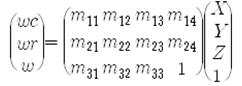
[수학식 2]를 참조하면, (c, r)은 영상좌표를 나타내고, (X, Y, Z)는 실제 좌표를 나타내며, w는 비례상수를 나타낸다. 한편, DLT 모델도 공선방정식 기반 모델과 유사하게 선정된 기준점들을 이용하여 행렬 M의 계수들을 구하게 된다. 다만, DLT 기반 모델은 선형방정식 모델이기 때문에 최소 제곱법을 사용하지는 않는다. 따라서, M행렬계수가 구해지면 실제 좌표 (X, Y, Z)에서 영상좌표 (c, r)을 계산할 수 있다. Referring to Equation 2, (c, r) represents image coordinates, (X, Y, Z) represents actual coordinates, and w represents a proportionality constant. Meanwhile, the DLT model also obtains the coefficients of the matrix M using reference points selected similarly to the collinear equation-based model. However, since the DLT-based model is a linear equation model, the least square method is not used. Therefore, when the M matrix coefficient is obtained, the image coordinates (c, r) can be calculated from the actual coordinates (X, Y, Z).
이와 같은 센서 모델식을 사용하면 가상 좌표계의 좌표와 영상 좌표간의 좌표 변환이 이루어질 수 있다. 가상 좌표계의 각 지점 X, Y 에 깊이 정보 H 값이 부여되는 것으로 깊이 영상이 생성된다. Using such a sensor model equation, the coordinate transformation between the coordinates of the virtual coordinate system and the image coordinates can be made. Depth images are generated by assigning depth information H values to the respective points X and Y of the virtual coordinate system.
도 3을 참조하여 다중 영상 정합 과정을 설명하면 다음과 같다. The multi-image matching process will be described with reference to FIG. 3.
먼저, 영상의 정합을 위해 3차원 모델을 생성할 평면 좌표상에 기준점(X, Y) 및 초기 깊이값(H)을 설정한다(S310). First, the reference point (X, Y) and the initial depth value (H) is set on the plane coordinates to generate the three-dimensional model for registration of the image (S310).
다음으로, 기준점 및 초기 깊이값에 대응하는 영상 좌표를 산출하고, 영상 좌표로부터 기준 영상 및 주변 영상에 대응되는 탐색 영역을 추출한다 (S320). 탐색 영역의 추출을 위해 수립된 센서 모델식에 X, Y 및 H 값을 대입하여 기준 영상 및 주변 영상에 해당하는 영상 좌표를 계산한다. 탐색 영역의 형태는 주로 사각형으로 설정되고, 탐색 영역의 크기는 사용자가 지정한 크기만큼 설정할 수 있다. 이와 같은 방식으로 영상 내에 가상 좌표 (X, Y, Z)에 해당하는 탐색 영역을 설정할 수 있다.Next, image coordinates corresponding to the reference point and the initial depth value are calculated, and a search region corresponding to the reference image and the surrounding image is extracted from the image coordinates (S320). Image coordinates corresponding to the reference image and the surrounding image are calculated by substituting X, Y and H values into the sensor model formula established for the extraction of the search region. The shape of the search area is mainly set to a rectangle, and the size of the search area may be set by a user-specified size. In this way, a search region corresponding to the virtual coordinates (X, Y, Z) can be set in the image.
다음으로, 추출된 탐색 영역들 중에서 기준 영상에 대응되는 탐색 영역을 기준으로 주변 영상에 대응되는 탐색 영역과의 유사성을 분석하여 기록한다 (S330). 이때, 유사성은 밝기값의 상관 계수, 밝기값의 변화량 차이, 에너지량 등 여러 가지 방법으로 계산할 수 있다.Next, among the extracted search areas, the similarity with the search area corresponding to the surrounding image is analyzed and recorded based on the search area corresponding to the reference image (S330). In this case, the similarity may be calculated by various methods such as a correlation coefficient of the brightness value, a difference in the amount of change in the brightness value, and an energy amount.
다음으로, 유사성의 계산이 완료되면 초기 깊이값을 일정 단위(ΔH)만큼 증가시킨다(S340). 초기 깊이값은 아래에서 살펴보는 바와 같이, 미리 설정된 최대 깊이값과 동일하거나 커질 때까지 증가시킨다.Next, when the calculation of the similarity is completed, the initial depth value is increased by a predetermined unit ΔH (S340). As shown below, the initial depth value is increased until it is equal to or larger than the preset maximum depth value.
다음으로, 증가된 깊이값을 미리 설정된 최대 깊이값(Hmax)과 비교한다(S350). 이때, 증가된 깊이값이 미리 설정된 최대 깊이값보다 작을 경우, 증가된 깊이값과 기준점을 이용하여 기준 영상 및 주변 영상으로부터 새로운 탐색 영역을 추출하고, 이에 대한 유사성을 분석하여 기록한다. 이러한 과정은 증가된 깊이값이 미리 설정된 최대 깊이값과 동일하거나 커질 때까지 반복하여 수행된다.Next, the increased depth value is compared with a preset maximum depth value Hmax (S350). In this case, when the increased depth value is smaller than the preset maximum depth value, a new search region is extracted from the reference image and the surrounding image using the increased depth value and the reference point, and the similarity is analyzed and recorded. This process is repeatedly performed until the increased depth value is equal to or larger than the preset maximum depth value.
한편, 증가된 깊이값이 미리 설정된 최대 깊이값보다 크거나 동일하게 될 경우, 이 조건을 만족할 때까지 반복하여 기록된 유사성 정보 중, 가장 높은 유사성을 나타낸 깊이값을 최종 깊이값으로 설정한다(S360). 이로써 기준점에서의 깊이값 결정이 완료된다.On the other hand, if the increased depth value is greater than or equal to the preset maximum depth value, the depth value showing the highest similarity among the similarity information repeatedly recorded until this condition is satisfied is set as the final depth value (S360). ). This completes the determination of the depth value at the reference point.
이와 같이, 가상 좌표상의 해당 영역에 존재하는 모든 기준점에서 다중 영상 정합 과정을 수행할 경우 정확한 깊이 영상을 추출할 수 있다.As such, when the multi-image registration process is performed at all reference points existing in the corresponding area on the virtual coordinates, an accurate depth image may be extracted.
도 5는 깊이값에 따른 유사도와 추출된 탐색영역의 관계를 도시한 도면이다.5 is a diagram illustrating a relationship between similarity according to a depth value and an extracted search region.
도 5는 깊이값을 미리 설정된 최대 깊이값과 동일하거나 커질 때까지 증가시키면서 유사성을 분석 및 기록한 결과이다. 이때, 유사도는 상관 계수로 계산한 것으로, 가장 유사도가 높은 경우를 1, 가장 유사도가 낮은 경우를 0으로 나타낸다. 도5를 살펴보면, 깊이값이 100일 때, 유사도는 0.6938로서 다른 결과에 비해 유사도가 가장 높다. 이때, 기준 영상과 주변 영상을 비교하면, 다른 결과에 비해 기준 영상과 주변 영상이 가장 잘 매칭되는 것을 확인할 수 있다.5 is a result of analyzing and recording the similarity while increasing the depth value until it is equal to or larger than the preset maximum depth value. In this case, the similarity is calculated by the correlation coefficient, and the case where the highest degree of similarity is high is 1 and the case where the degree of similarity is low is 0. Referring to FIG. 5, when the depth value is 100, the similarity is 0.6938, which is the highest in comparison with other results. In this case, when comparing the reference image and the surrounding image, it can be seen that the reference image and the surrounding image are best matched compared to other results.
도 6은 본 발명의 일 실시예에 따른 깊이 영상 생성 방법을 도시한 도면이다.6 illustrates a depth image generating method according to an embodiment of the present invention.
먼저, 기준 영상 카메라(210)를 배치하고, 복수의 주변 영상 카메라(220)를 상기 기준 영상 카메라(210)를 중심으로 미리 설정된 규칙에 따라 배치한다(S610). 이때, 주변 영상 카메라(220)는 2차원 배열의 형태로 배치할 수 있다.First, the
다음으로, 기준 영상 카메라(210)가 출력한 영상으로부터 기준 영상을 생성하고(S620), 복수의 주변 영상 카메라(220)가 출력한 영상으로부터 주변 영상을 생성한다(S630). Next, a reference image is generated from an image output by the reference image camera 210 (S620), and a peripheral image is generated from images output by the plurality of peripheral image cameras 220 (S630).
다음으로, 기준 영상 및 상기 주변 영상에 대해 다중 영상 정합을 수행하여(S640) 기준 영상에 대응되는 깊이 영상을 생성한다(S650). 다중 영상 정합을 수행하여 기준 영상에 대응되는 깊이 영상을 생성하는 과정은 도 3 및 도 4에서 설명한 바와 같다.Next, multi-image matching is performed on the reference image and the surrounding image (S640) to generate a depth image corresponding to the reference image (S650). A process of generating a depth image corresponding to the reference image by performing multi-image matching is as described with reference to FIGS. 3 and 4.
전술한 본 발명의 설명은 예시를 위한 것이며, 본 발명이 속하는 기술분야의 통상의 지식을 가진 자는 본 발명의 기술적 사상이나 필수적인 특징을 변경하지 않고서 다른 구체적인 형태로 쉽게 변형이 가능하다는 것을 이해할 수 있을 것이다. 그러므로 이상에서 기술한 실시예들은 모든 면에서 예시적인 것이며 한정적이 아닌 것으로 이해해야만 한다. 예를 들어, 단일형으로 설명되어 있는 각 구성 요소는 분산되어 실시될 수도 있으며, 마찬가지로 분산된 것으로 설명되어 있는 구성 요소들도 결합된 형태로 실시될 수 있다.The foregoing description of the present invention is intended for illustration, and it will be understood by those skilled in the art that the present invention may be easily modified in other specific forms without changing the technical spirit or essential features of the present invention. will be. It is therefore to be understood that the above-described embodiments are illustrative in all aspects and not restrictive. For example, each component described as a single entity may be distributed and implemented, and components described as being distributed may also be implemented in a combined form.
본 발명의 범위는 상기 상세한 설명보다는 후술하는 특허청구범위에 의하여 나타내어지며, 특허청구범위의 의미 및 범위 그리고 그 균등 개념으로부터 도출되는 모든 변경 또는 변형된 형태가 본 발명의 범위에 포함되는 것으로 해석되어야 한다.
The scope of the present invention is defined by the appended claims rather than the detailed description and all changes or modifications derived from the meaning and scope of the claims and their equivalents are to be construed as being included within the scope of the present invention do.
100: 깊이 영상 생성 시스템 110: 카메라부
120: 기준 영상 생성부 130: 주변 영상 생성부
140: 깊이 영상 생성부 141: 탐색 영역 추출부
143: 유사성 분석부 145: 깊이값 증가부
147: 깊이값 설정부 210: 기준 영상 카메라
220: 주변 영상 카메라 410: 영상 좌표계
420: 가상 좌표계 100: depth image generation system 110: camera unit
120: reference image generator 130: peripheral image generator
140: depth image generator 141: search region extractor
143: similarity analysis unit 145: depth value increasing unit
147: depth setting unit 210: reference video camera
220: peripheral video camera 410: video coordinate system
420: virtual coordinate system
Claims (10)
기준 영상 카메라 및 상기 기준 영상 카메라를 중심으로 미리 설정된 규칙에 따라 배치된 복수의 주변 영상 카메라를 포함하는 카메라부,
상기 기준 영상 카메라의 출력 영상으로부터 기준 영상을 생성하는 기준 영상 생성부,
상기 복수의 주변 영상 카메라의 출력 영상으로부터 주변 영상을 생성하는 주변 영상 생성부 및
상기 기준 영상 및 상기 주변 영상에 대해 다중 영상 정합을 수행하여 상기 기준 영상에 대응되는 깊이 영상을 생성하는 깊이 영상 생성부를 포함하되,
상기 깊이 영상 생성부는,
3차원 평면 좌표에 기준점 및 초기 깊이값을 설정하고, 상기 기준점 및 상기 초기 깊이값에 해당되는 영상 좌표에 기초하여 상기 기준 영상 또는 상기 주변 영상에 대응되는 탐색 영역을 추출하는 탐색 영역 추출부,
상기 기준 영상에 대응되는 탐색 영역을 기준으로 상기 주변 영상에 대응되는 탐색 영역과의 유사성을 분석하고 기록하는 유사성 분석부,
상기 초기 깊이값을 일정 단위만큼 증가시키는 깊이값 증가부 및
증가된 깊이값을 미리 설정된 최대 깊이값과 비교하여 상기 증가된 깊이값이 상기 미리 설정된 최대 깊이값보다 크거나 동일할 경우 기록된 유사성 중에서 가장 높은 유사성을 가진 깊이값을 최종 깊이값으로 설정하는 깊이값 설정부를 포함하며,
상기 깊이값 설정부는 상기 증가된 깊이값이 상기 미리 설정된 최대 깊이값보다 작을 경우, 상기 증가된 깊이값을 상기 초기 깊이값으로 설정하여 상기 탐색 영역을 다시 추출하고 유사성을 분석 및 기록하며, 깊이값을 일정 단위만큼 증가시키는 것인 깊이 영상 생성 시스템.
In the depth image generation system,
A camera unit including a reference video camera and a plurality of peripheral video cameras disposed according to a preset rule around the reference video camera;
A reference image generator for generating a reference image from the output image of the reference video camera;
A peripheral image generator configured to generate a peripheral image from output images of the plurality of peripheral image cameras;
Including a depth image generating unit for generating a depth image corresponding to the reference image by performing a multi-image matching on the reference image and the surrounding image,
The depth image generator,
A search region extraction unit configured to set a reference point and an initial depth value in three-dimensional plane coordinates, and extract a search region corresponding to the reference image or the surrounding image based on the reference point and the image coordinates corresponding to the initial depth value;
A similarity analyzer configured to analyze and record similarity with a search region corresponding to the surrounding image based on the search region corresponding to the reference image;
A depth value increasing unit for increasing the initial depth value by a predetermined unit; and
A depth for setting the depth value having the highest similarity among the recorded similarities as the final depth value when the increased depth value is greater than or equal to the preset maximum depth value by comparing the increased depth value with a preset maximum depth value. Value setting section,
The depth value setting unit sets the increased depth value as the initial depth value when the increased depth value is smaller than the preset maximum depth value, extracts the search area again, analyzes and records the similarity, and sets the depth value. To increase the depth by a predetermined unit.
상기 복수의 주변 영상 카메라는 좌우 및 상하 방향을 포함하는 2차원 배열로 배치된 것인 깊이 영상 생성 시스템.
The method of claim 1,
The plurality of peripheral image cameras are arranged in a two-dimensional array including a left and right and up and down direction.
상기 복수의 주변 영상 카메라는 원형으로 배치되되,
상기 기준 영상 카메라는 상기 복수의 주변 영상 카메라의 중심에 배치된 것인 깊이 영상 생성 시스템.
The method of claim 1,
The plurality of peripheral video cameras are arranged in a circle,
The reference image camera is a depth image generation system that is disposed in the center of the plurality of peripheral image cameras.
기준 영상 카메라 및 상기 기준 영상 카메라를 중심으로 미리 설정된 규칙에 따라 배치된 복수의 주변 영상 카메라를 포함하는 카메라부가 제공되는 단계,
상기 기준 영상 카메라가 출력한 영상으로부터 기준 영상을 생성하는 단계,
상기 복수의 주변 영상 카메라가 출력한 영상으로부터 주변 영상을 생성하는 단계 및
상기 기준 영상 및 상기 주변 영상에 대해 다중 영상 정합을 수행하여 상기 기준 영상에 대응되는 깊이 영상을 생성하는 단계를 포함하되,
상기 깊이 영상을 생성하는 단계는
3차원 평면 좌표에 기준점 및 초기 깊이값을 설정하는 단계,
상기 기준점 및 상기 초기 깊이값에 해당되는 영상 좌표에 기초하여 상기 기준 영상 또는 상기 주변 영상에 대응되는 탐색 영역을 추출하는 단계,
상기 기준 영상에 대응되는 탐색 영역을 기준으로 상기 주변 영상에 대응되는 탐색 영역과의 유사성을 분석하여 기록하는 단계,
상기 초기 깊이값을 일정 단위만큼 증가시키는 단계 및
상기 증가된 깊이값을 상기 미리 설정된 최대 깊이값과 비교하여 상기 증가된 깊이값이 상기 미리 설정된 최대 깊이값보다 크거나 동일할 경우 기록된 유사성 중에서 가장 높은 유사성을 가진 깊이값을 최종 깊이값으로 설정하는 단계를 포함하고,
상기 증가된 깊이값이 상기 미리 설정된 최대 깊이값보다 작을 경우 상기 증가된 깊이값을 상기 초기 깊이값으로 설정하여 상기 탐색 영역을 다시 추출하는 것인 깊이 영상 생성 방법.
In the depth image generation method,
Providing a camera unit including a reference video camera and a plurality of peripheral video cameras arranged according to a preset rule around the reference video camera;
Generating a reference image from the image output by the reference image camera;
Generating a peripheral image from the images output by the plurality of peripheral image cameras;
Generating a depth image corresponding to the reference image by performing multi-image matching on the reference image and the surrounding image;
Generating the depth image
Setting a reference point and an initial depth value in three-dimensional plane coordinates,
Extracting a search region corresponding to the reference image or the surrounding image based on the reference point and the image coordinates corresponding to the initial depth value;
Analyzing and recording similarity with the search region corresponding to the surrounding image based on the search region corresponding to the reference image;
Increasing the initial depth value by a predetermined unit; and
The depth value having the highest similarity among the recorded similarities is set as the final depth value when the increased depth value is greater than or equal to the preset maximum depth value by comparing the increased depth value with the preset maximum depth value. Including the steps of:
And extracting the search area again by setting the increased depth value as the initial depth value when the increased depth value is smaller than the preset maximum depth value.
상기 복수의 주변 영상 카메라는 좌우 및 상하 방향을 포함하는 2차원 배열로 배치시킨 것인 깊이 영상 생성 방법.
The method according to claim 6,
And the plurality of peripheral image cameras are arranged in a two-dimensional array including left and right and up and down directions.
상기 복수의 주변 영상 카메라는 원형으로 배치시키되,
상기 기준 영상 카메라는 상기 복수의 주변 영상 카메라의 중심에 배치시킨 것인 깊이 영상 생성 방법.
The method according to claim 6,
The plurality of peripheral video cameras are arranged in a circle,
The reference video camera is a depth image generating method that is disposed in the center of the plurality of peripheral video cameras.
Priority Applications (1)
| Application Number | Priority Date | Filing Date | Title |
|---|---|---|---|
| KR1020120068228A KR101358430B1 (en) | 2012-06-25 | 2012-06-25 | Depth Image Generation Method and System |
Applications Claiming Priority (1)
| Application Number | Priority Date | Filing Date | Title |
|---|---|---|---|
| KR1020120068228A KR101358430B1 (en) | 2012-06-25 | 2012-06-25 | Depth Image Generation Method and System |
Publications (1)
| Publication Number | Publication Date |
|---|---|
| KR101358430B1 true KR101358430B1 (en) | 2014-02-05 |
Family
ID=50269856
Family Applications (1)
| Application Number | Title | Priority Date | Filing Date |
|---|---|---|---|
| KR1020120068228A Expired - Fee Related KR101358430B1 (en) | 2012-06-25 | 2012-06-25 | Depth Image Generation Method and System |
Country Status (1)
| Country | Link |
|---|---|
| KR (1) | KR101358430B1 (en) |
Cited By (1)
| Publication number | Priority date | Publication date | Assignee | Title |
|---|---|---|---|---|
| KR20200072346A (en) * | 2018-12-12 | 2020-06-22 | 서울과학기술대학교 산학협력단 | Device and method for deriving object coordinate |
Citations (4)
| Publication number | Priority date | Publication date | Assignee | Title |
|---|---|---|---|---|
| KR100267259B1 (en) | 1998-02-20 | 2000-10-16 | 박호군 | Dense depth extraction method using multiple camera images and intermediate images synthesis method using said method |
| KR100793076B1 (en) | 2005-12-08 | 2008-01-10 | 한국전자통신연구원 | Edge-adaptive stereo / multipoint image matching device and method thereof |
| KR20090055803A (en) * | 2007-11-29 | 2009-06-03 | 광주과학기술원 | Method and apparatus for generating multiview depth map and method for generating variance in multiview image |
| JP2011199556A (en) | 2010-03-19 | 2011-10-06 | Nippon Hoso Kyokai <Nhk> | Stereoscopy imaging device, stereoscopic signal generator, and program |
-
2012
- 2012-06-25 KR KR1020120068228A patent/KR101358430B1/en not_active Expired - Fee Related
Patent Citations (4)
| Publication number | Priority date | Publication date | Assignee | Title |
|---|---|---|---|---|
| KR100267259B1 (en) | 1998-02-20 | 2000-10-16 | 박호군 | Dense depth extraction method using multiple camera images and intermediate images synthesis method using said method |
| KR100793076B1 (en) | 2005-12-08 | 2008-01-10 | 한국전자통신연구원 | Edge-adaptive stereo / multipoint image matching device and method thereof |
| KR20090055803A (en) * | 2007-11-29 | 2009-06-03 | 광주과학기술원 | Method and apparatus for generating multiview depth map and method for generating variance in multiview image |
| JP2011199556A (en) | 2010-03-19 | 2011-10-06 | Nippon Hoso Kyokai <Nhk> | Stereoscopy imaging device, stereoscopic signal generator, and program |
Cited By (2)
| Publication number | Priority date | Publication date | Assignee | Title |
|---|---|---|---|---|
| KR20200072346A (en) * | 2018-12-12 | 2020-06-22 | 서울과학기술대학교 산학협력단 | Device and method for deriving object coordinate |
| KR102151250B1 (en) * | 2018-12-12 | 2020-09-02 | 서울과학기술대학교 산학협력단 | Device and method for deriving object coordinate |
Similar Documents
| Publication | Publication Date | Title |
|---|---|---|
| EP3392831B1 (en) | Three-dimensional sensor system and three-dimensional data acquisition method | |
| CN110390719B (en) | Reconstruction equipment based on flight time point cloud | |
| US8452081B2 (en) | Forming 3D models using multiple images | |
| Khoshelham | Accuracy analysis of kinect depth data | |
| US8447099B2 (en) | Forming 3D models using two images | |
| US10182223B2 (en) | Three-dimensional imaging system | |
| KR101706093B1 (en) | System for extracting 3-dimensional coordinate and method thereof | |
| US8687044B2 (en) | Depth camera compatibility | |
| CN106802138A (en) | A kind of 3 D scanning system and its scan method | |
| KR101181199B1 (en) | Stereoscopic image generation method of background terrain scenes, system using the same and recording medium for the same | |
| KR20090055803A (en) | Method and apparatus for generating multiview depth map and method for generating variance in multiview image | |
| WO2012096747A1 (en) | Forming range maps using periodic illumination patterns | |
| EP2531980A2 (en) | Depth camera compatibility | |
| CN106875435B (en) | Method and system for obtaining depth image | |
| CN104581124A (en) | Method and apparatus for generating depth map of a scene | |
| JP2016537901A (en) | Light field processing method | |
| KR20160127057A (en) | Structured stereo | |
| CN107463659B (en) | Object searching method and device | |
| Shim et al. | Time-of-flight sensor and color camera calibration for multi-view acquisition | |
| JP6285686B2 (en) | Parallax image generation device | |
| CN110651166B (en) | Optoelectronic device for collecting 3D data | |
| Weinmann et al. | Fusing passive and active sensed images to gain infrared-textured 3D models | |
| KR101358430B1 (en) | Depth Image Generation Method and System | |
| CN105578173A (en) | Rapid three-dimensional space projection and camera shooting visual identification system | |
| Jiang et al. | Automated 3-D animation from snooker videos with information-theoretical optimization |
Legal Events
| Date | Code | Title | Description |
|---|---|---|---|
| PA0109 | Patent application |
St.27 status event code: A-0-1-A10-A12-nap-PA0109 |
|
| N231 | Notification of change of applicant | ||
| PN2301 | Change of applicant |
St.27 status event code: A-3-3-R10-R13-asn-PN2301 St.27 status event code: A-3-3-R10-R11-asn-PN2301 |
|
| A201 | Request for examination | ||
| PA0201 | Request for examination |
St.27 status event code: A-1-2-D10-D11-exm-PA0201 |
|
| D13-X000 | Search requested |
St.27 status event code: A-1-2-D10-D13-srh-X000 |
|
| D14-X000 | Search report completed |
St.27 status event code: A-1-2-D10-D14-srh-X000 |
|
| E902 | Notification of reason for refusal | ||
| PE0902 | Notice of grounds for rejection |
St.27 status event code: A-1-2-D10-D21-exm-PE0902 |
|
| E13-X000 | Pre-grant limitation requested |
St.27 status event code: A-2-3-E10-E13-lim-X000 |
|
| P11-X000 | Amendment of application requested |
St.27 status event code: A-2-2-P10-P11-nap-X000 |
|
| P13-X000 | Application amended |
St.27 status event code: A-2-2-P10-P13-nap-X000 |
|
| E701 | Decision to grant or registration of patent right | ||
| PE0701 | Decision of registration |
St.27 status event code: A-1-2-D10-D22-exm-PE0701 |
|
| GRNT | Written decision to grant | ||
| PR0701 | Registration of establishment |
St.27 status event code: A-2-4-F10-F11-exm-PR0701 |
|
| PR1002 | Payment of registration fee |
St.27 status event code: A-2-2-U10-U11-oth-PR1002 Fee payment year number: 1 |
|
| PG1601 | Publication of registration |
St.27 status event code: A-4-4-Q10-Q13-nap-PG1601 |
|
| R18-X000 | Changes to party contact information recorded |
St.27 status event code: A-5-5-R10-R18-oth-X000 |
|
| P22-X000 | Classification modified |
St.27 status event code: A-4-4-P10-P22-nap-X000 |
|
| LAPS | Lapse due to unpaid annual fee | ||
| PC1903 | Unpaid annual fee |
St.27 status event code: A-4-4-U10-U13-oth-PC1903 Not in force date: 20170128 Payment event data comment text: Termination Category : DEFAULT_OF_REGISTRATION_FEE |
|
| P22-X000 | Classification modified |
St.27 status event code: A-4-4-P10-P22-nap-X000 |
|
| R18-X000 | Changes to party contact information recorded |
St.27 status event code: A-5-5-R10-R18-oth-X000 |
|
| R18-X000 | Changes to party contact information recorded |
St.27 status event code: A-5-5-R10-R18-oth-X000 |
|
| PC1903 | Unpaid annual fee |
St.27 status event code: N-4-6-H10-H13-oth-PC1903 Ip right cessation event data comment text: Termination Category : DEFAULT_OF_REGISTRATION_FEE Not in force date: 20170128 |
|
| PN2301 | Change of applicant |
St.27 status event code: A-5-5-R10-R13-asn-PN2301 St.27 status event code: A-5-5-R10-R11-asn-PN2301 |
|
| R18-X000 | Changes to party contact information recorded |
St.27 status event code: A-5-5-R10-R18-oth-X000 |
|
| R18-X000 | Changes to party contact information recorded |
St.27 status event code: A-5-5-R10-R18-oth-X000 |