KR101335391B1 - Video composing apparatus and its method - Google Patents
Video composing apparatus and its method Download PDFInfo
- Publication number
- KR101335391B1 KR101335391B1 KR1020100033310A KR20100033310A KR101335391B1 KR 101335391 B1 KR101335391 B1 KR 101335391B1 KR 1020100033310 A KR1020100033310 A KR 1020100033310A KR 20100033310 A KR20100033310 A KR 20100033310A KR 101335391 B1 KR101335391 B1 KR 101335391B1
- Authority
- KR
- South Korea
- Prior art keywords
- camera
- factor
- motion capture
- image
- motion
- Prior art date
- Legal status (The legal status is an assumption and is not a legal conclusion. Google has not performed a legal analysis and makes no representation as to the accuracy of the status listed.)
- Active
Links
Images


Classifications
-
- G—PHYSICS
- G06—COMPUTING OR CALCULATING; COUNTING
- G06T—IMAGE DATA PROCESSING OR GENERATION, IN GENERAL
- G06T19/00—Manipulating 3D models or images for computer graphics
- G06T19/006—Mixed reality
-
- G—PHYSICS
- G06—COMPUTING OR CALCULATING; COUNTING
- G06T—IMAGE DATA PROCESSING OR GENERATION, IN GENERAL
- G06T7/00—Image analysis
- G06T7/20—Analysis of motion
- G06T7/246—Analysis of motion using feature-based methods, e.g. the tracking of corners or segments
-
- G—PHYSICS
- G06—COMPUTING OR CALCULATING; COUNTING
- G06T—IMAGE DATA PROCESSING OR GENERATION, IN GENERAL
- G06T7/00—Image analysis
- G06T7/80—Analysis of captured images to determine intrinsic or extrinsic camera parameters, i.e. camera calibration
-
- G—PHYSICS
- G06—COMPUTING OR CALCULATING; COUNTING
- G06T—IMAGE DATA PROCESSING OR GENERATION, IN GENERAL
- G06T2207/00—Indexing scheme for image analysis or image enhancement
- G06T2207/10—Image acquisition modality
- G06T2207/10016—Video; Image sequence
-
- G—PHYSICS
- G06—COMPUTING OR CALCULATING; COUNTING
- G06T—IMAGE DATA PROCESSING OR GENERATION, IN GENERAL
- G06T2207/00—Indexing scheme for image analysis or image enhancement
- G06T2207/30—Subject of image; Context of image processing
- G06T2207/30204—Marker
- G06T2207/30208—Marker matrix
-
- G—PHYSICS
- G06—COMPUTING OR CALCULATING; COUNTING
- G06T—IMAGE DATA PROCESSING OR GENERATION, IN GENERAL
- G06T2207/00—Indexing scheme for image analysis or image enhancement
- G06T2207/30—Subject of image; Context of image processing
- G06T2207/30244—Camera pose
Landscapes
- Engineering & Computer Science (AREA)
- Physics & Mathematics (AREA)
- General Physics & Mathematics (AREA)
- Theoretical Computer Science (AREA)
- Computer Vision & Pattern Recognition (AREA)
- Multimedia (AREA)
- Computer Graphics (AREA)
- Computer Hardware Design (AREA)
- General Engineering & Computer Science (AREA)
- Software Systems (AREA)
- Studio Devices (AREA)
- Image Processing (AREA)
Abstract
본 발명은 영상 합성 기법에 관한 것으로, 모션 캡쳐 장비와 촬영 카메라를 동기화한 후에, 모션 캡쳐를 위해 부착된 마커의 3차원 모션 캡쳐 데이터를 획득하고, 촬영 카메라를 통해 녹화된 비디오 영상에서 마커의 2차원 위치 데이터를 획득하며, 3차원 모션 캡쳐 데이터 및 2차원 위치 데이터를 이용하여 촬영 카메라의 외부 인자 및 내부 인자를 추적한 후에, 추적된 외부 인자 및 내부 인자를 이용하여 촬영 카메라의 모든 인자를 보정하고, 실사 촬영 영상과 애니메이션 영상을 효과적으로 합성할 수 있다.The present invention relates to an image synthesizing technique, and after synchronizing a motion capture device with a photographing camera, obtaining 3D motion capture data of a marker attached for motion capturing, and performing 2D of a marker in a video image recorded through the photographing camera. After acquiring the dimensional position data and tracking the external and internal factors of the shooting camera using the 3D motion capture data and the 2D position data, correcting all the factors of the shooting camera using the tracked external and internal factors. In addition, it is possible to effectively synthesize the live-photographed video and the animated video.
Description
본 발명은 영상 합성 기법에 관한 것으로, 더욱 상세하게는 영상 콘텐츠 제작에 사용되는 CG/실사 영상 합성(computer-generated/real image composition)을 위해 고해상도 비디오 촬영 카메라의 모션을 추적(tracking)하여 영상을 합성(composing)하는데 적합한 영상 합성 장치 및 그 방법에 관한 것이다.The present invention relates to an image synthesis technique, and more particularly, to track an image by tracking a motion of a high-resolution video camera for computer-generated / real image composition used in the production of image content. An image synthesizing apparatus suitable for composing and a method thereof are provided.
본 발명은 지식경제부의 IT성장동력기술개발사업의 일환으로 수행한 연구로부터 도출된 것이다[과제관리번호: 2007-S-051-03, 과제명: 디지털 크리쳐 제작 S/W 개발].The present invention is derived from the research conducted as part of the IT growth engine technology development project of the Ministry of Knowledge Economy [Task management number: 2007-S-051-03, task name: digital creature production S / W development].
잘 알려진 바와 같이, CG/실사 영상 합성에 이용되는 고해상도 비디오 촬영 카메라 모션 추적 및 합성 기술은 컴퓨터 그래픽스(computer graphics) 기술 기반의 시각 효과를 이용한 영화, 드라마, 광고와 같은 영화/방송용 영상 콘텐츠 제작 분야에서, 실제 배우 및 소품의 모션 캡쳐(motion capture) 데이터를 이용하여 만들어진 CG 영상과 현장에서 모션 캡쳐와 동시에 촬영된 고해상도 실사 비디오 영상을 합성하여 보다 자연스럽고 사실감 있는 CG/실사 합성 영상 콘텐츠를 제작하는데 반드시 필요한 기술이다.As is well known, the high-resolution video camera motion tracking and compositing techniques used for CG / real image synthesis are used in the production of film / broadcasting video content such as movies, dramas, and commercials using visual effects based on computer graphics technology. In order to produce more natural and realistic CG / real-world composite video contents by combining CG images made using motion capture data of real actors and props and high-resolution live-action video images taken simultaneously with motion capture in the field It is a necessary skill.
종래의 시각 효과를 위한 CG/실사 영상 합성을 위해 촬영 카메라의 모션을 추적하기 위한 기술은 팬(pen)/틸트(tilt) 센서, 인코더(encoder) 등을 포함하는 모션 센서 시스템(motion sensor system)과 복수의 자이로스코프(gyroscope), 가속도계(accelerometer) 등을 포함하는 관성 항법 시스템(inertial navigation system)을 촬영 카메라에 장착하여 카메라 모션을 추적하는 센서 부착 방식, 카메라 모션 추적을 위한 카메라 표적(camera-target)을 촬영 카메라에 장착하여 이를 별도의 카메라 표적 추적 장비를 통해서 추적하여 촬영 카메라 모션을 역으로 산출하는 표적 부착 방식 등이 제안되어 있다.Techniques for tracking the motion of a photographic camera for CG / real image synthesis for conventional visual effects include a motion sensor system including a pen / tilt sensor, an encoder, and the like. A sensor-attached system that tracks camera motion by mounting an inertial navigation system, including a plurality of gyroscopes and accelerometers, to the shooting camera, and a camera target for camera motion tracking. A target attachment method for mounting a target) to a photographing camera and tracking it through a separate camera target tracking device to calculate the photographing camera motion in reverse has been proposed.
하지만, 상술한 바와 같은 종래의 센서 부착 방식이나 표적 부착 방식은 카메라 추적을 위하여 별도의 모션 추적 센서나 추적용 카메라 표적의 사전 제작 과정, 복잡한 설치 과정 등을 실행해야 하는 제약이 따르며, 카메라 모션이나 촬영 조건에 따라서 각기 다른 모션 센서를 사용해야 하거나 표적 부착 방식을 변경해야 하는 문제점이 있다. However, the conventional method of attaching a sensor or attaching a target as described above has a limitation of performing a separate motion tracking sensor or a pre-production process of a tracking camera target, a complicated installation process, and the like for camera tracking. Depending on the shooting conditions, there is a problem in that different motion sensors must be used or target attachment methods must be changed.
예를 들면, 센서 부착 방식의 경우 카메라의 회전 모션만이 변하는 고정 촬영 카메라의 모션 추적은 팬/틸트 센서, 인코더 등을 포함하는 카메라 센서 시스템만으로 충분하지만, 카메라의 이동 모션도 함께 변하는 이동 촬영 카메라의 모션 추적을 위해서는 카메라 센서 시스템뿐만 아니라 복수의 자이로스코프, 가속도계 등을 포함하는 관성 항법 시스템을 추가적으로 사용해야 한다. For example, in the case of a sensor attached method, the motion tracking of a fixed shooting camera in which only the rotational motion of the camera changes is sufficient for a camera sensor system including a pan / tilt sensor, an encoder, etc. In addition to the camera sensor system, an inertial navigation system that includes multiple gyroscopes, accelerometers, etc. must be used to track the motion of the sensor.
또한, 표적 부착 방식의 경우에는 카메라에 부착된 표적을 추적하는 표적 추적 장치로부터 촬영 카메라가 멀어지는 경우에는 표적이 부착된 영역을 크도록, 반대로 가까워지는 경우에는 표적이 부착된 영역을 작게 하는 등 표적 제작 및 부착 방식을 변경해 주어야 하는 것과 같이 추적용 카메라 표적의 사전 제작 및 설치 과정이 복잡한 문제점이 있었다.In the case of the target attachment method, if the shooting camera moves away from the target tracking device that tracks the target attached to the camera, the area to which the target is attached is increased, and if the target is closer, the area to which the target is attached is reduced. The prefabrication and installation process of the tracking camera target has been a complex problem, such as the need to change the fabrication and attachment method.
한편, 촬영 카메라의 추적 기술은 촬영 카메라의 회전과 이동 모션 관련된 카메라 외부 인자는 추적할 수 있으나, 촬영 카메라의 렌즈와 관련된 카메라 내부 인자는 추적과 보정을 수행하기 어려운 점이 있는데, 예를 들어 센서 부착 방식의 경우에는 카메라 줌(zoom)과 포커스(focus) 변화에 따른 렌즈 초점 길이의 변화를 추적하기 위해서는 별도의 줌/포커스 센서와 추가적인 인코더를 카메라 센서 시스템에 설치해야 할 뿐만 아니라, 인코딩 값을 카메라 내부 인자 값으로 변환하기 위해서는 복잡한 사전 보정(calibration) 과정을 수행해야 하는 문제점이 있다.On the other hand, the tracking technology of the shooting camera can track the camera external factors related to the rotation and movement of the shooting camera, but the camera internal factors related to the lens of the shooting camera are difficult to perform tracking and correction. In the case of the method, in order to track the change of the lens focal length according to the camera zoom and focus change, a separate zoom / focus sensor and an additional encoder are installed in the camera sensor system, and the encoding value is not displayed. There is a problem in that a complicated precalibration process must be performed in order to convert to an internal factor value.
또한, 표적 부착 방식의 경우에는 촬영 카메라의 회전과 이동 모션과 관련된 외부 인자는 카메라 표적으로부터 역으로 추적할 수 있으나, 방식 자체의 특성상 카메라 렌즈와 관련된 내부 인자는 추적과 보정을 할 수 없는 문제점이 있다.In addition, in the case of the target attachment method, the external factors related to the rotational and moving motion of the photographing camera can be tracked backward from the camera target, but the internal factors related to the camera lens cannot be tracked and corrected due to the characteristics of the method itself. have.
상술한 바와 같은 문제점들 때문에, 종래에 제안된 센서 부착 방식의 촬영 카메라 추적 기술은 모션 센서 시스템과 관성 항법 시스템과 같은 하드웨어 구현 및 장착에 많은 비용과 시간이 소요되며, 표적 부착 방식의 카메라 추적 기술은 내부 인자의 추적과 보정을 할 수 없는 제약으로 내부 인자는 변하지 않고 모션과 관련된 외부 인자만이 변하는 경우에만 사용할 수 있지만, 고해상도 비디오 촬영 카메라를 사용할 경우에는 내부 인자 값에 작은 변화라도 있으면 정확하게 CG 영상과 촬영 비디오 영상을 합성할 수 없으므로 반드시 카메라 모션과 관련된 외부 인자와 함께 렌즈와 관련된 내부 인자도 추적 및 보정되어야 한다.Due to the problems as described above, the conventionally proposed sensor-mounted camera tracking technology is expensive and time-consuming to implement and mount hardware such as motion sensor system and inertial navigation system, and target tracking camera tracking technology. Can not be used to track and correct the internal parameters, but can only be used when the internal parameters are not changed and only the external factors related to motion are changed. Since video and captured video images cannot be synthesized, the internal factors associated with the lens must be tracked and corrected along with the external factors associated with camera motion.
뿐만 아니라, 종래의 촬영 카메라 추적 기술은 촬영 카메라 좌표계를 기준으로 카메라 모션을 추적하기 때문에 모션 캡쳐 좌표계를 기준으로 복원되는 모션 캡쳐 데이터와 촬영 카메라 모션 데이터의 합성이 용이하지 않아, 모션 캡쳐 데이터를 이용한 실제 배우 및 소품의 CG 영상과 실사 촬영 영상을 합성하기 위한 CG/실사 영상 합성 시스템에 적용하는데 또한 어려운 점이 있다.In addition, since conventional camera tracking technology tracks camera motion based on a camera coordinate system, motion capture data reconstructed based on a motion capture coordinate system is not easily synthesized with motion camera capture data. It is also difficult to apply to a CG / real image synthesis system for synthesizing real-life actors and props' CG images and live-action shots.
이에 따라, 본 발명은 모션 캡쳐 데이터와 촬영 카메라의 모션을 이용하여 영상을 합성할 수 있는 영상 합성 장치 및 그 방법을 제공하고자 한다.Accordingly, an aspect of the present invention is to provide an image synthesizing apparatus and method for synthesizing an image using motion capture data and motion of a photographing camera.
또한, 본 발명은 모션 캡쳐 데이터를 이용하여 촬영 카메라 인자를 보정함으로써, 효과적으로 영상을 합성할 수 있는 영상 합성 장치 및 그 방법을 제공하고자 한다.In addition, the present invention is to provide an image synthesizing apparatus and method for synthesizing an image effectively by correcting a photographing camera factor using motion capture data.
본 발명의 목적은 이상에서 언급한 목적으로 제한되지 않으며, 언급되지 않은 또 다른 목적들은 아래의 기재로부터 본 발명이 속하는 기술 분야에서 통상의 지식을 가진 자에게 명확하게 이해될 수 있을 것이다.The object of the present invention is not limited to the above-mentioned object, and other objects that are not mentioned will be clearly understood by those skilled in the art from the following description.
본 발명의 일 실시 예에 따르면, 모션 캡쳐 장비와 촬영 카메라를 동기화시키는 동기화부와, 모션 캡쳐를 위해 부착된 마커의 3차원 모션 캡쳐 데이터를 복원하는 3차원 복원부와, 상기 촬영 카메라를 통해 촬영된 비디오 영상에서 상기 마커의 2차원 위치 데이터를 검출하는 2차원 검출부와, 상기 복원된 3차원 모션 캡쳐 데이터 및 검출된 2차원 위치 데이터를 이용하여 상기 비디오 영상의 모든 프레임에 대한 상기 촬영 카메라의 외부 인자 및 내부 인자를 추적하는 추적부와, 상기 모든 프레임에 대한 추적이 완료되면, 상기 추적된 외부 인자 및 내부 인자를 보정하는 보정부와, 상기 보정된 외부 인자 및 내부 인자를 이용하여 기 설정된 CG 영상과 상기 비디오 영상을 합성하는 합성부를 포함하는 영상 합성 장치가 제공된다.According to an embodiment of the present invention, the synchronization unit for synchronizing the motion capture equipment and the photographing camera, a three-dimensional restoring unit for restoring the three-dimensional motion capture data of the attached marker for motion capture, and photographing through the photographing camera A two-dimensional detector configured to detect two-dimensional position data of the marker in the captured video image, and an outer portion of the photographing camera for all frames of the video image by using the restored three-dimensional motion capture data and the detected two-dimensional position data. A tracking unit for tracking a factor and an internal factor, a tracking unit for correcting the tracked external factor and an internal factor when tracking of all the frames is completed, and a preset CG using the corrected external factor and the internal factor Provided is an image synthesizing apparatus including a synthesizing unit for synthesizing an image and the video image.
또한, 상기 동기화부는, 젠락 신호와 타임 코드 신호를 이용하여 상기 모션 캡쳐 장비 및 촬영 카메라의 내부 클락을 상호 동기화하는 영상 합성 장치가 제공된다.In addition, the synchronization unit is provided with an image synthesizing apparatus for synchronizing the internal clock of the motion capture device and the photographing camera using a genlock signal and a time code signal.
또한, 상기 동기화부는, 상기 타임 코드 신호를 이용하여 상기 모션 캡쳐 장비의 동작 속도를 상기 촬영 카메라의 녹화 속도의 정수배가 되도록 제어하고, 상기 모션 캡쳐와 상기 비디오 영상의 녹화 실행 시작 시간 및 종료 시간을 제어하는 영상 합성 장치가 제공된다.The synchronization unit may be configured to control the operation speed of the motion capture device to be an integer multiple of the recording speed of the photographing camera using the time code signal, and to start and end the recording execution start time and end time of the motion capture and the video image. There is provided an image synthesizing apparatus for controlling.
또한, 상기 3차원 복원부는, 모션 캡쳐 좌표계의 X축, Y축, Z축 상의 좌표 값에 따라 상기 3차원 모션 캡쳐 데이터를 복원하는 영상 합성 장치가 제공된다.The 3D reconstruction unit is provided with an image synthesizing apparatus for reconstructing the 3D motion capture data according to coordinate values on the X, Y, and Z axes of the motion capture coordinate system.
또한, 상기 2차원 검출부는, 영상 좌표계의 U축과 V축 상의 좌표 값을 이용하여 광학적 오차 함수 값이 최소값을 갖도록 상기 2차원 위치 데이터를 검출하는 영상 합성 장치가 제공된다.In addition, the two-dimensional detector is provided with an image synthesizing apparatus for detecting the two-dimensional position data using the coordinate values on the U axis and V axis of the image coordinate system so that the optical error function value has a minimum value.
또한, 상기 추적부는, 상기 촬영 카메라의 모션과 관련된 상기 외부 인자와, 상기 촬영 카메라의 렌즈와 관련된 상기 내부 인자를 추적하는 영상 합성 장치가 제공된다.In addition, the tracking unit is provided with an image synthesizing apparatus for tracking the external factor associated with the motion of the photographing camera and the internal factor associated with the lens of the photographing camera.
또한, 상기 추적부는, 카메라 회전 모션 인자와 카메라 이동 모션 인자를 포함하는 상기 외부 인자를 추적하는 영상 합성 장치가 제공된다.In addition, the tracking unit is provided with an image synthesizing apparatus for tracking the external factor including a camera rotation motion factor and a camera movement motion factor.
또한, 상기 추적부는, 카메라 렌즈의 초점 거리 인자와, 상기 카메라 렌즈의 광중심 내부 인자와, 상기 카메라 렌즈의 방상 방향 및 접선 방향에 대한 렌즈 왜곡 인자를 포함하는 상기 내부 인자를 추적하는 영상 합성 장치가 제공된다.The tracking unit may further include an image synthesizing apparatus including a focal length factor of a camera lens, an optical center internal factor of the camera lens, and a lens distortion factor of a direction and a tangential direction of the camera lens. Is provided.
또한, 상기 보정부는, 카메라 회전 모션 인자와 카메라 이동 모션 인자를 포함하는 상기 외부 인자와, 카메라 렌즈의 초점 거리 인자와, 상기 카메라 렌즈의 광중심 내부 인자와, 상기 카메라 렌즈의 방상 방향 및 접선 방향에 대한 렌즈 왜곡 인자를 포함하는 상기 내부 인자에 대한 최적화를 통해 상기 외부 인자 및 내부 인자를 보정하는 영상 합성 장치가 제공된다.The correction unit may further include an external factor including a camera rotational motion factor and a camera movement motion factor, a focal length factor of the camera lens, an optical center internal factor of the camera lens, and a radial direction and a tangential direction of the camera lens. An image synthesizing apparatus is provided that corrects the external and internal factors by optimizing the internal factors including a lens distortion factor for.
또한, 상기 합성부는, 모션 캡쳐 좌표계를 기준으로 상기 외부 인자 및 내부 인자가 추적 및 보정된 상기 촬영 카메라를 렌더링을 위한 그래픽 카메라로 설정하고, 상기 설정된 그래픽 카메라를 이용하여 상기 CG 영상 및 비디오 영상을 합성하는 영상 합성 장치가 제공된다.The synthesizing unit may be configured to set the photographing camera whose external and internal factors are tracked and corrected based on a motion capture coordinate system as a graphic camera for rendering, and to set the CG image and video image using the set graphic camera. An image synthesizing apparatus for synthesizing is provided.
본 발명의 다른 실시 예에 따르면, 모션 캡쳐 장비와 촬영 카메라를 동기화시키는 단계와, 모션 캡쳐를 위해 부착된 마커의 3차원 모션 캡쳐 데이터를 복원하는 단계와, 상기 촬영 카메라를 통해 촬영된 비디오 영상에서 상기 마커의 2차원 위치 데이터를 검출하는 단계와, 상기 복원된 3차원 모션 캡쳐 데이터 및 검출된 2차원 위치 데이터를 이용하여 상기 비디오 영상의 모든 프레임에 대한 상기 촬영 카메라의 외부 인자 및 내부 인자를 추적하는 단계와, 상기 모든 프레임에 대한 추적이 완료되면, 상기 추적된 외부 인자 및 내부 인자를 보정하는 단계와, 상기 보정된 외부 인자 및 내부 인자를 이용하여 기 설정된 CG 영상과 상기 비디오 영상을 합성하는 단계를 포함하는 영상 합성 방법이 제공된다.According to another embodiment of the present invention, the step of synchronizing the motion capture device and the shooting camera, restoring the 3D motion capture data of the attached marker for motion capture, and in the video image captured by the shooting camera Detecting two-dimensional position data of the marker, and using the reconstructed three-dimensional motion capture data and the detected two-dimensional position data to track external and internal factors of the photographing camera for every frame of the video image. And when the tracking of all the frames is completed, correcting the tracked external factors and internal factors, and synthesizing a preset CG image and the video images using the corrected external factors and internal factors. There is provided an image synthesis method comprising the steps.
또한, 상기 동기화시키는 단계는, 젠락 신호와 타임 코드 신호를 이용하여 상기 모션 캡쳐 장비 및 촬영 카메라의 내부 클락을 상호 동기화하는 방식으로 수행되는 영상 합성 방법이 제공된다.The synchronizing may be performed by synchronizing the internal clocks of the motion capture device and the photographing camera using a genlock signal and a time code signal.
또한, 상기 동기화시키는 단계는, 상기 타임 코드 신호를 이용하여 상기 모션 캡쳐 장비의 동작 속도를 상기 촬영 카메라의 녹화 속도의 정수배가 되도록 제어하고, 상기 모션 캡쳐와 상기 비디오 영상의 녹화 실행 시작 시간 및 종료 시간을 제어하는 방식으로 수행되는 영상 합성 방법이 제공된다.The synchronizing may include controlling the operation speed of the motion capture device to be an integer multiple of the recording speed of the photographing camera using the time code signal, and starting and ending the execution time of recording the motion capture and the video image. There is provided an image synthesizing method performed by controlling the time.
또한, 상기 3차원 모션 캡쳐 데이터를 복원하는 단계는, 모션 캡쳐 좌표계의 X축, Y축, Z축 상의 좌표 값에 따라 상기 3차원 모션 캡쳐 데이터를 복원하는 방식으로 수행되는 영상 합성 방법이 제공된다.In addition, the step of restoring the three-dimensional motion capture data, there is provided an image synthesis method performed by restoring the three-dimensional motion capture data according to the coordinate values on the X, Y, Z axis of the motion capture coordinate system. .
또한, 상기 2차원 위치 데이터를 검출하는 단계는, 영상 좌표계의 U축과 V축 상의 좌표 값을 이용하여 광학적 오차 함수 값이 최소값을 갖도록 상기 2차원 위치 데이터를 검출하는 방식으로 수행되는 영상 합성 방법이 제공된다.The detecting of the two-dimensional position data may be performed by detecting the two-dimensional position data in such a manner that the optical error function has a minimum value using coordinate values on the U and V axes of the image coordinate system. This is provided.
또한, 상기 외부 인자 및 내부 인자를 추적하는 단계는, 상기 촬영 카메라의 모션과 관련된 상기 외부 인자와, 상기 촬영 카메라의 렌즈와 관련된 상기 내부 인자를 추적하는 방식으로 수행되는 영상 합성 방법이 제공된다.In addition, the tracking of the external factor and the internal factor is provided by an image synthesizing method performed by tracking the external factor related to the motion of the photographing camera and the internal factor related to the lens of the photographing camera.
또한, 상기 외부 인자 및 내부 인자를 추적하는 단계는, 카메라 회전 모션 인자와 카메라 이동 모션 인자를 포함하는 상기 외부 인자를 추적하는 방식으로 수행되는 영상 합성 방법이 제공된다.In addition, the tracking of the external factor and the internal factor is provided by an image synthesizing method performed by tracking the external factor including a camera rotation motion factor and a camera movement motion factor.
또한, 상기 외부 인자 및 내부 인자를 추적하는 단계는, 카메라 렌즈의 초점 거리 인자와, 상기 카메라 렌즈의 광중심 내부 인자와, 상기 카메라 렌즈의 방상 방향 및 접선 방향에 대한 렌즈 왜곡 인자를 포함하는 상기 내부 인자를 추적하는 방식으로 수행되는 영상 합성 방법이 제공된다.The tracking of the external factor and the internal factor may include: a focal length factor of the camera lens, an optical center internal factor of the camera lens, and lens distortion factors of the radial and tangential directions of the camera lens; An image synthesis method performed by tracking internal factors is provided.
또한, 상기 추적된 외부 인자 및 내부 인자를 보정하는 단계는, 카메라 회전 모션 인자와 카메라 이동 모션 인자를 포함하는 상기 외부 인자와, 카메라 렌즈의 초점 거리 인자와, 상기 카메라 렌즈의 광중심 내부 인자와, 상기 카메라 렌즈의 방상 방향 및 접선 방향에 대한 렌즈 왜곡 인자를 포함하는 상기 내부 인자에 대한 최적화를 통해 상기 외부 인자 및 내부 인자를 보정하는 방식으로 수행되는 영상 합성 방법이 제공된다.In addition, correcting the tracked external factor and internal factor may include: the external factor including a camera rotational motion factor and a camera movement motion factor, a focal length factor of the camera lens, and an optical center internal factor of the camera lens; The image synthesis method is performed by correcting the external factor and the internal factor by optimizing the internal factor including lens distortion factors in the axial direction and the tangential direction of the camera lens.
또한, 상기 비디오 영상을 합성하는 단계는, 모션 캡쳐 좌표계를 기준으로 상기 외부 인자 및 내부 인자가 추적 및 보정된 상기 촬영 카메라를 렌더링을 위한 그래픽 카메라로 설정하고, 상기 설정된 그래픽 카메라를 이용하여 상기 CG 영상 및 비디오 영상을 합성하는 방식으로 수행되는 영상 합성 방법이 제공된다.The synthesizing of the video image may include setting the photographing camera whose external and internal factors are tracked and corrected based on a motion capture coordinate system as a graphic camera for rendering, and using the set graphic camera. There is provided an image synthesizing method performed by synthesizing an image and a video image.
본 발명은, CG/실사 영상 합성에 있어서 모션 캡쳐 데이터를 이용하여 고해상도의 비디오 촬영 카메라의 모션을 추적 및 합성하는 기법에 관한 것으로, 모션 추적을 위한 별도의 카메라 모션 센서의 사용이나 카메라 표적을 카메라에 부착하지 않고, 실제 배우 및 소품에 부착된 마커의 모션 캡쳐 데이터를 이용하여 현장에서 녹화에 사용된 고해상도의 비디오 촬영 카메라의 모션을 정확하게 추적하며, 이를 모션 캡쳐 데이터와 합성할 수 있다.The present invention relates to a technique for tracking and synthesizing the motion of a high resolution video recording camera using motion capture data in CG / real image synthesis, and using a separate camera motion sensor for motion tracking or a camera target. The motion capture data of markers attached to actual actors and props can be accurately tracked and synthesized with the motion capture data using the motion capture data of high resolution video recording cameras used for recording in the field.
즉, 본 발명은 모션 캡쳐 장비를 통해 복원된 배우 및 소품의 마커 기반 3차원 모션 캡쳐 데이터와 촬영 카메라를 통해 녹화된 배우 및 소품의 마커에 대한 2차원 위치 데이터를 동기화시킴으로써, 촬영 카메라의 모션과 관련된 외부 인자를 매 프레임에서 추적할 수 있을 뿐만 아니라, 고해상도 카메라 렌즈와 관련된 내부 인자들도 동시에 추적 및 보정할 수 있으며, CG/실사 영상 합성에 있어서 실제 배우 및 소품의 모션 캡쳐 데이터와 고해상도 촬영 카메라 모션의 자연스러운 합성을 수행함으로써, 고해상도 CG/실사 합성 영상 콘텐츠 제작에 필요한 고해상도 비디오 촬영 카메라 추적의 정확성과 안정성을 확보할 수 있다.That is, the present invention synchronizes the marker-based three-dimensional motion capture data of the actors and props restored through the motion capture device with the two-dimensional position data of the markers of the actors and the props recorded through the shooting camera, In addition to tracking the relevant external factors at every frame, the internal factors associated with the high-resolution camera lens can also be tracked and corrected simultaneously, and the motion capture data of real actors and props and the high-resolution cameras in CG / real image synthesis. By performing natural compositing of motion, it is possible to secure the accuracy and stability of tracking high-resolution video cameras required for producing high-resolution CG / real composite video content.
도 1은 본 발명의 일 실시 예에 따라 모션 캡쳐 데이터를 통해 촬영 카메라의 모션을 추적하여 영상을 합성하는데 적합한 영상 합성 장치의 블록 구성도,
도 2는 본 발명의 실시 예에 따라 모션 캡쳐 데이터를 통해 촬영 카메라의 모션을 추적하여 영상을 합성하는 것을 설명하기 위한 도면,
도 3은 본 발명의 다른 실시 예에 따라 모션 캡쳐 데이터를 통해 촬영 카메라의 모션을 추적하여 영상을 합성하는 과정을 도시한 플로우차트,
도 4a 및 도 4b는 본 발명의 실시 예에 따라 모션 캡쳐 데이터를 통해 촬영 카메라의 모션을 추적하여 영상을 합성하는 제 1 예시도,
도 5a 및 도 5b는 본 발명의 실시 예에 따라 모션 캡쳐 데이터를 통해 촬영 카메라의 모션을 추적하여 영상을 합성하는 제 2 예시도.1 is a block diagram of an image synthesizing apparatus suitable for synthesizing an image by tracking a motion of a photographing camera through motion capture data according to an embodiment of the present invention;
FIG. 2 is a diagram for describing synthesizing an image by tracking a motion of a photographing camera through motion capture data according to an embodiment of the present invention; FIG.
3 is a flowchart illustrating a process of synthesizing an image by tracking a motion of a photographing camera through motion capture data according to another embodiment of the present invention;
4A and 4B are first exemplary diagrams of synthesizing an image by tracking a motion of a photographing camera through motion capture data according to an embodiment of the present invention;
5A and 5B are second exemplary diagrams of synthesizing an image by tracking a motion of a photographing camera through motion capture data according to an exemplary embodiment of the present invention.
본 발명은, 모션 캡쳐 장비와 촬영 카메라를 동기화한 후에, 모션 캡쳐를 위해 부착된 마커의 3차원 모션 캡쳐 데이터를 획득하고, 촬영 카메라를 통해 녹화된 비디오 영상에서 마커의 2차원 위치 데이터를 획득하며, 3차원 모션 캡쳐 데이터 및 2차원 위치 데이터를 이용하여 촬영 카메라의 외부 인자 및 내부 인자를 추적한 후에, 추적된 외부 인자 및 내부 인자를 이용하여 촬영 카메라의 모든 인자를 보정하고, 실사 촬영 영상과 애니메이션 영상을 합성한다는 것이며, 이러한 기술적 수단을 통해 종래 기술에서의 문제점을 해결할 수 있다.The present invention, after synchronizing the motion capture device and the shooting camera, obtains the three-dimensional motion capture data of the attached marker for motion capture, and obtains the two-dimensional position data of the marker in the video image recorded through the shooting camera After tracking the external and internal factors of the photographing camera by using the 3D motion capture data and the 2D position data, correcting all the factors of the photographing camera by using the tracked external and internal factors, It is to synthesize the animation image, it can be solved the problems in the prior art through this technical means.
본 발명의 이점 및 특징, 그리고 그것들을 달성하는 방법은 첨부되는 도면과 함께 상세하게 후술되어 있는 실시 예들을 참조하면 명확해질 것이다. 그러나 본 발명은 이하에서 개시되는 실시 예들에 한정되는 것이 아니라 서로 다른 다양한 형태로 구현될 수 있으며, 단지 본 실시 예들은 본 발명의 개시가 완전하도록 하고, 본 발명이 속하는 기술분야에서 통상의 지식을 가진 자에게 발명의 범주를 완전하게 알려주기 위해 제공되는 것이며, 본 발명은 청구항의 범주에 의해 정의될 뿐이다. 명세서 전체에 걸쳐 동일 참조 부호는 동일 구성 요소를 지칭한다.BRIEF DESCRIPTION OF THE DRAWINGS The advantages and features of the present invention and the manner of achieving them will become apparent with reference to the embodiments described in detail below with reference to the accompanying drawings. The present invention may, however, be embodied in many different forms and should not be construed as being limited to the embodiments set forth herein. Rather, these embodiments are provided so that this disclosure will be thorough and complete, and will fully convey the concept of the invention to those skilled in the art. Is provided to fully convey the scope of the invention to those skilled in the art, and the invention is only defined by the scope of the claims. Like reference numerals refer to like elements throughout.
본 발명의 실시 예들을 설명함에 있어서 공지 기능 또는 구성에 대한 구체적인 설명이 본 발명의 요지를 불필요하게 흐릴 수 있다고 판단되는 경우에는 그 상세한 설명을 생략할 것이다. 그리고 후술되는 용어들은 본 발명의 실시 예에서의 기능을 고려하여 정의된 용어들로서 이는 사용자, 운용자의 의도 또는 관례 등에 따라 달라질 수 있다. 그러므로 그 정의는 본 명세서 전반에 걸친 내용을 토대로 내려져야 할 것이다. In the following description of the present invention, a detailed description of known functions and configurations incorporated herein will be omitted when it may make the subject matter of the present invention rather unclear. The following terms are defined in consideration of the functions in the embodiments of the present invention, which may vary depending on the intention of the user, the intention or the custom of the operator. Therefore, the definition should be based on the contents throughout this specification.
첨부된 블록도의 각 블록과 흐름도의 각 단계의 조합들은 컴퓨터 프로그램 인스트럭션들에 의해 수행될 수도 있다. 이들 컴퓨터 프로그램 인스트럭션들은 범용 컴퓨터, 특수용 컴퓨터 또는 기타 프로그램 가능한 데이터 프로세싱 장비의 프로세서에 탑재될 수 있으므로, 컴퓨터 또는 기타 프로그램 가능한 데이터 프로세싱 장비의 프로세서를 통해 수행되는 그 인스트럭션들이 블록도의 각 블록 또는 흐름도의 각 단계에서 설명된 기능들을 수행하는 수단을 생성하게 된다. 이들 컴퓨터 프로그램 인스트럭션들은 특정 방식으로 기능을 구현하기 위해 컴퓨터 또는 기타 프로그램 가능한 데이터 프로세싱 장비를 지향할 수 있는 컴퓨터 이용 가능 또는 컴퓨터 판독 가능 메모리에 저장되는 것도 가능하므로, 그 컴퓨터 이용가능 또는 컴퓨터 판독 가능 메모리에 저장된 인스트럭션들은 블록도의 각 블록 또는 흐름도 각 단계에서 설명된 기능을 수행하는 인스트럭션 수단을 내포하는 제조 품목을 생산하는 것도 가능하다. 컴퓨터 프로그램 인스트럭션들은 컴퓨터 또는 기타 프로그램 가능한 데이터 프로세싱 장비 상에 탑재되는 것도 가능하므로, 컴퓨터 또는 기타 프로그램 가능한 데이터 프로세싱 장비 상에서 일련의 동작 단계들이 수행되어 컴퓨터로 실행되는 프로세스를 생성해서 컴퓨터 또는 기타 프로그램 가능한 데이터 프로세싱 장비를 수행하는 인스트럭션들은 블록도의 각 블록 및 흐름도의 각 단계에서 설명된 기능들을 실행하기 위한 단계들을 제공하는 것도 가능하다. Each block of the accompanying block diagrams and combinations of steps of the flowchart may be performed by computer program instructions. These computer program instructions may be loaded into a processor of a general purpose computer, special purpose computer, or other programmable data processing apparatus so that the instructions, which may be executed by a processor of a computer or other programmable data processing apparatus, And means for performing the functions described in each step are created. These computer program instructions may also be stored in a computer usable or computer readable memory capable of directing a computer or other programmable data processing apparatus to implement the functionality in a particular manner so that the computer usable or computer readable memory It is also possible for the instructions stored in the block diagram to produce a manufacturing item containing instruction means for performing the functions described in each block or flowchart of the block diagram. Computer program instructions may also be mounted on a computer or other programmable data processing equipment, such that a series of operating steps may be performed on the computer or other programmable data processing equipment to create a computer-implemented process to create a computer or other programmable data. Instructions that perform processing equipment may also provide steps for performing the functions described in each block of the block diagram and in each step of the flowchart.
또한, 각 블록 또는 각 단계는 특정된 논리적 기능(들)을 실행하기 위한 하나 이상의 실행 가능한 인스트럭션들을 포함하는 모듈, 세그먼트 또는 코드의 일부를 나타낼 수 있다. 또, 몇 가지 대체 실시 예들에서는 블록들 또는 단계들에서 언급된 기능들이 순서를 벗어나서 발생하는 것도 가능함을 주목해야 한다. 예컨대, 잇달아 도시되어 있는 두 개의 블록들 또는 단계들은 사실 실질적으로 동시에 수행되는 것도 가능하고 또는 그 블록들 또는 단계들이 때때로 해당하는 기능에 따라 역순으로 수행되는 것도 가능하다.Also, each block or each step may represent a module, segment, or portion of code that includes one or more executable instructions for executing the specified logical function (s). It should also be noted that in some alternative embodiments, the functions mentioned in the blocks or steps may occur out of order. For example, the two blocks or steps shown in succession may in fact be executed substantially concurrently or the blocks or steps may sometimes be performed in the reverse order, depending on the functionality involved.
이하, 첨부된 도면을 참조하여 본 발명의 실시 예를 상세히 설명하기로 한다.Hereinafter, embodiments of the present invention will be described in detail with reference to the accompanying drawings.
도 1은 본 발명의 일 실시 예에 따라 모션 캡쳐 데이터를 통해 촬영 카메라의 모션을 추적하여 영상을 합성하는데 적합한 영상 합성 장치의 블록 구성도로서, 동기화부(102), 3차원 복원부(104), 2차원 검출부(106), 추적부(108), 보정부(110), 합성부(112) 등을 포함할 수 있다.1 is a block diagram of an image synthesizing apparatus suitable for synthesizing an image by tracking a motion of a photographing camera through motion capture data according to an embodiment of the present invention. The
도 1을 참조하면, 동기화부(102)는 모션을 캡쳐하는 모션 캡쳐 장비와 영상 녹화를 수행하는 촬영 카메라를 시간적으로 동기화시키는 것으로, 서로 다른 동작 속도를 갖는 모션 캡쳐 장비와 촬영 카메라에 젠락(gen-lock) 신호와 타임 코드(time-code) 신호를 연결하여 모션 캡쳐 장비와 촬영 카메라의 내부 클락(clock)을 상호 동기화한다.Referring to FIG. 1, the
또한, 동기화부(102)는 타임 코드 기반으로 모션 캡쳐와 영상 녹화의 실행 시작 시간 및 종료 시간을 제어하는데, 모션 캡쳐 장비의 동작 속도를 촬영 카메라의 녹화 속도의 정수배가 되도록 제어한다. 이에 따라 모션 캡쳐 장비를 통해 복원된 3차원 모션 캡쳐 데이터와 촬영 카메라를 통해 녹화된 고해상도의 비디오 영상이 오차없이 동기화될 수 있다.In addition, the
예를 들면, 동기화부(102)는 모션 캡쳐를 수행하는 모션 캡쳐 장비와 비디오 녹화를 수행하는 고해상도의 촬영 카메라의 서로 다른 동작 속도에 대해 시간적 동기화를 수행하는데, 모션 캡쳐 장비의 동작 속도를 촬영 카메라의 동작 속도의 정수배(예를 들면, 2배, 3배, 4배 등)로 설정함으로써, 모션 캡쳐 장비를 통해 복원된 모션 캡쳐 데이터 프레임과 촬영 카메라를 통해 녹화된 고해상도의 비디오 영상 프레임이 오차없이 동기화될 수 있다.For example, the
또한, 동기화부(102)는 젠락 신호를 통해 모션 캡쳐 장비와 촬영 카메라의 내부 클락을 동기화하고, 타임 코드 신호를 기반으로 모션 캡쳐와 영상 녹화의 시작 시간 및 종료 시간이 일치하도록 제어함으로써, 동일한 길이의 모션 캡쳐 데이터와 고해상도의 비디오 데이터를 획득할 수 있으며, 동기화된 모션 캡쳐 데이터와 녹화 영상의 총 프레임수(![]()
![]()
![]()
![]()
그리고, 3차원 복원부(104)는 모션 캡쳐 장비를 통해 마커의 모션을 캡쳐한 모션 캡쳐 데이터를 복원하는 것으로, 모션 캡쳐 장비를 통해 실제 배우, 실제 소품 등에 부착된 마커의 모션 캡쳐 데이터를 복원하여 촬영 카메라의 모션 추적을 위한 3차원 모션 데이터를 획득한다.In addition, the
예를 들면, 모션 캡쳐를 위해 예를 들면, 실제 배우, 실제 소품 등에 부착된 마커에 대한 모션 캡쳐와 영상 녹화를 수행하는데, 마커의 총 개수는 ![]()
![]()
![]()
![]()
![]()
![]()
![]()
![]()
이 때, 모션 캡쳐 장비는 도 2에 도시한 바와 같이 3차원 공간상의 모션 캡쳐 좌표계(![]()
![]()
![]()
![]()
![]()
![]()
![]()
![]()
![]()
![]()
![]()
![]()
![]()
![]()
다음에, 2차원 검출부(106)는 촬영 카메라를 통해 녹화된 비디오 영상에서 마커의 2차원 위치를 검출하는 것으로, 촬영 카메라를 통해 녹화된 고해상도의 각 비디오 프레임 영상에서 마커의 2차원 위치를 검출하여 촬영 카메라의 모션 추적을 위한 2차원 위치 데이터를 획득한다.Next, the two-
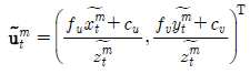
예를 들면, 2차원 검출부(106)는 촬영 카메라를 통해 녹화된 t 번째 비디오 프레임 영상(![]()
![]()
![]()
![]()
![]()
![]()
![]()
![]()
![]()
![]()
![]()
![]()
![]()
![]()
![]()
![]()
![]()
![]()
![]()
![]()
여기에서, ![]()
![]()
![]()
![]()
![]()
![]()
![]()
![]()
![]()
![]()
![]()
![]()
![]()
![]()
![]()
![]()
한편, 다수의 모션 캡쳐 카메라를 사용하는 모션 캡쳐 장비와는 달리 하나의 촬영 카메라로 비디오 영상을 녹화하는 경우 마커의 가려짐(occlusion) 현상이 발생할 수 있으며, 이 경우 비디오 영상에서 마커의 위치를 검출할 수 없기 때문에, 이러한 마커의 가려짐 현상이 발생하여 t 번째 비디오 프레임 영상(![]()
![]()
![]()
![]()
![]()
![]()
![]()
![]()
그리고, 추적부(108)는 3차원 모션 캡쳐 데이터와 2차원 위치 데이터를 이용하여 촬영 카메라의 외부 인자 및 내부 인자를 추적하는 것으로, 예를 들면, 실제 배우, 실제 소품 등에 부착된 마커의 3차원 모션 캡쳐 데이터와 2차원 위치 데이터를 이용하여 모션 캡쳐 데이터 좌표계를 기준으로 하는 촬영 카메라의 모션에 관련된 외부 인자와 촬영 카메라 렌즈의 초점 거리와 관련된 내부 인자를 각 영상 프레임에서 연속적으로 계산하는 방식으로 촬영 카메라의 외부 인자 및 내부 인자를 추적한다.The
예를 들면, 추적부(108)는 t 번째 프레임에서 복원된 마커의 모드 3차원 위치(![]()
![]()
![]()
![]()
![]()
![]()
![]()
![]()
![]()
![]()
![]()
![]()
![]()
![]()
또한, t 번째 프레임에서 촬영 카메라의 렌즈와 관련된 내부 인자는 ![]()
![]()
![]()
![]()
![]()
![]()
![]()
![]()
![]()
![]()
![]()
![]()
![]()
![]()
![]()
![]()
![]()
![]()
그리고, 추적부(108)는 촬영 카메라의 인자 중에서 t 번째 프레임에 대한 외부 인자(![]()
![]()
![]()
![]()
![]()
![]()
![]()
![]()
![]()
![]()
![]()
![]()
![]()
![]()
여기에서, 벡터 함수 ![]()
![]()
![]()
![]()
상기한 수학식 3에서, ![]()
![]()
![]()
![]()
![]()
![]()
![]()
![]()
![]()
![]()
![]()
![]()
![]()
![]()
![]()
![]()
![]()
![]()
![]()
![]()
![]()
![]()
![]()
![]()
또한, 상기 수학식 3에서 ![]()

![]()
![]()
![]()

한편, 보정부(110)는 촬영 카메라의 외부 인자 및 내부 인자를 보정하여 최적화하는 것으로, 모든 영상 프레임에 대한 촬영 카메라의 외부 인자 및 내부 인자의 추적이 완료되면, 추적된 촬영 카메라의 외부 인자 및 내부 인자를 이용하여 촬영 카메라 렌즈의 광중심 및 왜곡과 관련된 내부 인자를 포함하는 촬영 카메라의 외부 인자 및 외부 인자를 보정하여 모든 인자에 대한 최적화를 수행한다.Meanwhile, the
예를 들면, 보정부(110)는 모든 프레임에 대한 촬영 카메라의 모션의 추적이 완료되면 아래의 수학식 6과 같은 오차 함수가 최소값을 갖도록 모든 프레임 상에서의 촬영 카메라 모션과 관련된 외부 인자(![]()
![]()
![]()
![]()
![]()
![]()
![]()
![]()

이어서, 합성부(112)는 모델 및 소품과 합성될 애니메이션을 설정하여 실사 촬영 영상과 애니메이션 영상을 합성하는 것으로, 모션 캡쳐 데이터를 이용하여 배우 및 소품과 합성될 CG 모델의 애니메이션을 설정한 후, 각 프레임에서 모션 캡쳐 좌표계를 기준으로 추적 및 보정된 촬영 카메라를 렌더링을 위한 그래픽 카메라로 설정하고, 배우 및 소품에 대한 고해상도의 실사 촬영 영상과 그래픽 카메라를 통해 렌더링된 CG 애니메이션 영상을 합성한다.Subsequently, the
예를 들면, 합성부(112)는 모든 프레임 상에서의 마커의 3차원 위치 데이터(![]()
![]()
![]()
![]()
![]()
![]()
![]()
![]()
![]()
![]()
![]()
![]()
![]()
![]()
![]()
![]()
![]()
![]()
![]()
![]()
다음에, 그래픽 좌표계(![]()
![]()
![]()
![]()
![]()
![]()
![]()
![]()
![]()
![]()
여기에서, ![]()
![]()
![]()
![]()
![]()
![]()
![]()
![]()
따라서, 모션 캡쳐 장비와 촬영 카메라를 동기화한 후에, 모션 캡쳐를 위해 부착된 마커의 3차원 모션 캡쳐 데이터를 획득하고, 촬영 카메라를 통해 녹화된 비디오 영상에서 마커의 2차원 위치 데이터를 획득하며, 3차원 모션 캡쳐 데이터 및 2차원 위치 데이터를 이용하여 촬영 카메라의 외부 인자 및 내부 인자를 추적한 후에, 추적된 외부 인자 및 내부 인자를 이용하여 촬영 카메라의 모든 인자를 보정하고, 실사 촬영 영상과 애니메이션 영상을 효과적으로 합성할 수 있다.Therefore, after synchronizing the motion capture device with the photographing camera, the 3D motion capture data of the attached marker is acquired for motion capture, the 2D position data of the marker is obtained from the video image recorded through the photographing camera, and 3 After the external and internal factors of the photographing camera are tracked using the dimensional motion capture data and the 2D positional data, all the factors of the photographing camera are corrected by using the tracked external and internal factors. Can be effectively synthesized.
다음에, 상술한 바와 같은 구성을 갖는 영상 합성 장치에서 모션 캡쳐 장비와 촬영 카메라를 동기화한 후에, 마커의 3차원 모션 캡쳐 데이터 및 2차원 위치 데이터를 획득하며, 3차원 모션 캡쳐 데이터 및 2차원 위치 데이터를 이용하여 촬영 카메라의 외부 인자 및 내부 인자를 추적 및 보정하고, 실사 촬영 영상과 애니메이션 영상을 합성하는 과정에 대해 설명한다.Next, after synchronizing the motion capture device and the photographing camera in the image synthesizing apparatus having the above-described configuration, the 3D motion capture data and the 2D position data of the marker are obtained, and the 3D motion capture data and the 2D position are obtained. The process of tracking and correcting the external and internal factors of the photographing camera using the data and synthesizing the real-life captured image and the animated image will be described.
도 3은 본 발명의 다른 실시 예에 따라 모션 캡쳐 데이터를 통해 촬영 카메라의 모션을 추적하여 영상을 합성하는 과정을 도시한 플로우차트이다.3 is a flowchart illustrating a process of synthesizing an image by tracking a motion of a photographing camera through motion capture data according to another embodiment of the present invention.
도 3을 참조하면, 영상 합성 장치의 영상 합성 모드에서(단계302), 동기화부(102)에서는 모션 캡쳐를 수행하는 모션 캡쳐 장비와 비디오 녹화를 수행하는 고해상도의 촬영 카메라의 서로 다른 동작 속도에 대해 시간적 동기화를 수행한다(단계304). 여기에서, 시간적 동기화는 모션 캡쳐 장비의 동작 속도를 촬영 카메라의 동작 속도의 정수배(예를 들면, 2배, 3배, 4배 등)로 설정하는 방식으로 수행됨으로써, 모션 캡쳐 장비를 통해 복원된 모션 캡쳐 데이터 프레임과 촬영 카메라를 통해 녹화된 고해상도의 비디오 영상 프레임이 오차없이 동기화될 수 있다.Referring to FIG. 3, in the image synthesizing mode of the image synthesizing apparatus (step 302), the
또한, 동기화부(102)에서는 젠락 신호를 통해 모션 캡쳐 장비와 촬영 카메라의 내부 클락을 동기화하고, 타임 코드 신호를 기반으로 모션 캡쳐와 영상 녹화의 시작 시간 및 종료 시간이 일치하도록 제어함으로써, 동일한 길이의 모션 캡쳐 데이터와 고해상도의 비디오 데이터를 획득할 수 있으며, 동기화된 모션 캡쳐 데이터와 녹화 영상의 총 프레임수와 각 프레임의 인덱스는 각각의 데이터와 함께 저장될 수 있다.In addition, the
그리고, 모션 캡쳐를 위해 예를 들면, 실제 배우, 실제 소품 등에 모션 캡쳐용 마커를 부착한다(단계306).Then, for example, a motion capture marker is attached to a real actor, a real prop, or the like for motion capture (step 306).
다음에, 모션 캡쳐용 마크에 대한 모션 캡쳐와 예를 들면, 실제 배우, 실제 소품 등에 대한 영상 녹화를 수행한다(단계308).Next, motion capture of the mark for motion capture and video recording of, for example, a real actor, a real prop, and the like are performed (step 308).
한편, 3차원 복원부(104)에서는 모션 캡쳐 장비를 통해 실제 배우, 실제 소품 등에 부착된 마커의 모션 캡쳐 데이터를 복원하여 촬영 카메라의 모션 추적을 위한 3차원 모션 데이터(즉, 3차원 마커 위치)를 획득한다(단계310). 여기에서, 마커의 총 개수는 ![]()
![]()
![]()
![]()
![]()
![]()
![]()
![]()
이 때, 모션 캡쳐 장비는 도 2에 도시한 바와 같이 3차원 공간상의 모션 캡쳐 좌표계(![]()
![]()
![]()
![]()
![]()
![]()
![]()
![]()
![]()
![]()
![]()
![]()
![]()
![]()
다음에, 2차원 검출부(106)에서는 촬영 카메라를 통해 녹화된 고해상도의 각 비디오 프레임 영상에서 마커의 2차원 위치를 검출하여 촬영 카메라의 모션 추적을 위한 2차원 위치 데이터를 획득한다(단계312).Next, the two-
일 예로서, 2차원 검출부(106)에서는 촬영 카메라를 통해 녹화된 t 번째 비디오 프레임 영상(![]()
![]()
![]()
![]()
![]()
![]()
![]()
![]()
![]()
![]()
![]()
![]()
![]()
![]()
![]()
![]()
![]()
![]()
이 때, 다수의 모션 캡쳐 카메라를 사용하는 모션 캡쳐 장비와는 달리 하나의 촬영 카메라로 비디오 영상을 녹화하는 경우 마커의 가려짐 현상이 발생할 수 있으며, 이 경우 비디오 영상에서 마커의 위치를 검출할 수 없기 때문에, 이러한 마커의 가려짐 현상이 발생하여 t 번째 비디오 프레임 영상(![]()
![]()
![]()
![]()
![]()
![]()
![]()
![]()
그리고, 추적부(108)에서는 마커의 3차원 모션 캡쳐 데이터와 2차원 위치 데이터를 이용하여 모션 캡쳐 데이터 좌표계를 기준으로 하는 촬영 카메라의 모션에 관련된 외부 인자와 촬영 카메라 렌즈의 초점 거리와 관련된 내부 인자를 각 영상 프레임에서 연속적으로 계산하는 방식으로 촬영 카메라의 외부 인자 및 내부 인자를 추적한다(단계314).In addition, the
일 예로서, 추적부(108)에서는 t 번째 프레임에서 복원된 마커의 모드 3차원 위치(![]()
![]()
![]()
![]()
![]()
![]()
![]()
![]()
![]()
![]()
![]()
![]()
![]()
![]()
또한, t 번째 프레임에서 촬영 카메라의 렌즈와 관련된 내부 인자는 ![]()
![]()
![]()
![]()
![]()
![]()
![]()
![]()
![]()
![]()
![]()
![]()
이 때, 추적부(108)에서는 촬영 카메라의 인자 중에서 t 번째 프레임에 대한 외부 인자(![]()
![]()
![]()
![]()
![]()
![]()
![]()
![]()
![]()
![]()
![]()
![]()
상기 수학식 2에서, 벡터 함수 ![]()
![]()
![]()
![]()
![]()
![]()
![]()
![]()
![]()
![]()
![]()
![]()
![]()
![]()
![]()
![]()
![]()
![]()
![]()
![]()
![]()
![]()
![]()
![]()
![]()
![]()
또한, 상기 수학식 3에서 ![]()
![]()
![]()
![]()
다음에, 모든 영상 프레임에 대해 단계310의 3차원 마크 위치 복원과, 단계312의 2차원 마커 위치 검출과, 단계314의 카메라 인자 추적 과정을 반복 수행한다(단계316).Next, the 3D mark position restoration in
그리고, 보정부(110)에서는 모든 영상 프레임에 대한 촬영 카메라의 외부 인자 및 내부 인자의 추적이 완료되면, 추적된 촬영 카메라의 외부 인자 및 내부 인자를 이용하여 촬영 카메라 렌즈의 광중심 및 왜곡과 관련된 내부 인자를 포함하는 촬영 카메라의 외부 인자 및 외부 인자를 보정하여 모든 인자에 대한 최적화를 수행한다(단계318).In addition, when the tracking of the external factor and the internal factor of the photographing camera is completed for all the image frames, the
예를 들면, 보정부(110)에서는 모든 프레임에 대한 촬영 카메라의 모션의 추적이 완료되면 상기 수학식 6과 같은 오차 함수가 최소값을 갖도록 모든 프레임 상에서의 촬영 카메라 모션과 관련된 외부 인자(![]()
![]()
![]()
![]()
![]()
![]()
![]()
![]()
이어서, 합성부(112)에서는 모션 캡쳐 데이터를 이용하여 배우 및 소품과 합성될 CG 모델의 애니메이션을 설정한 후, 각 프레임에서 모션 캡쳐 좌표계를 기준으로 추적 및 보정된 촬영 카메라를 렌더링을 위한 그래픽 카메라로 설정하고, 배우 및 소품에 대한 고해상도의 실사 촬영 영상과 그래픽 카메라를 통해 렌더링된 CG 애니메이션 영상을 합성한다(단계320).Subsequently, the
예를 들면, 모든 프레임 상에서의 마커의 3차원 위치 데이터(![]()
![]()
![]()
![]()
![]()
![]()
![]()
![]()
![]()
![]()
![]()
![]()
![]()
![]()
![]()
![]()
![]()
![]()
다음에, 그래픽 좌표계(![]()
![]()
![]()
![]()
![]()
![]()
![]()
![]()
여기에서, ![]()
![]()
![]()
![]()
![]()
![]()
![]()
![]()
예를 들면, 도 4a 및 도 4b는 본 발명의 실시 예에 따라 모션 캡쳐 데이터를 통해 촬영 카메라의 모션을 추적하여 영상을 합성하는 제 1 예시도이고, 도 5a 및 도 5b는 본 발명의 실시 예에 따라 모션 캡쳐 데이터를 통해 촬영 카메라의 모션을 추적하여 영상을 합성하는 제 2 예시도로서, 도 4a 및 도 5a는 1920ㅧ1080 픽셀의 고해상도 실사 영상을 나타내고, 소품에 부착된 마커에 대한 3차원 모션 캡쳐 데이터 및 2차원 위치 데이터를 이용하여 촬영 카메라 모션을 추적한 후, 촬영 카메라의 외부 인자 및 내부 인자를 보정하여 CG 영상과 실사 영상을 합성하면, 도 4b 및 도 5b와 같이 1920ㅧ1080 픽셀의 합성 영상이 효과적으로 생성될 수 있음을 알 수 있다.For example, FIGS. 4A and 4B are first exemplary diagrams of synthesizing an image by tracking motion of a photographing camera through motion capture data according to an embodiment of the present invention, and FIGS. 5A and 5B are embodiments of the present invention. According to the second exemplary view of synthesizing the image by tracking the motion of the shooting camera through the motion capture data, Figures 4a and 5a shows a high-resolution live image of 1920 × 1080 pixels, three-dimensional for the marker attached to the prop After tracking the shooting camera motion by using the motion capture data and the two-dimensional position data, and combining the CG image and the real image by correcting the external and internal factors of the shooting camera, 1920 ㅧ 1080 pixels as shown in Figs. 4b and 5b. It can be seen that the synthesized image of can be effectively generated.
따라서, 모션 캡쳐 장비와 촬영 카메라를 동기화한 후에, 모션 캡쳐를 위해 부착된 마커의 3차원 모션 캡쳐 데이터를 획득하고, 촬영 카메라를 통해 녹화된 비디오 영상에서 마커의 2차원 위치 데이터를 획득하며, 3차원 모션 캡쳐 데이터 및 2차원 위치 데이터를 이용하여 촬영 카메라의 외부 인자 및 내부 인자를 추적한 후에, 추적된 외부 인자 및 내부 인자를 이용하여 촬영 카메라의 모든 인자를 보정하고, 실사 촬영 영상과 애니메이션 영상을 효과적으로 합성할 수 있다.Therefore, after synchronizing the motion capture device with the photographing camera, the 3D motion capture data of the attached marker is acquired for motion capture, the 2D position data of the marker is obtained from the video image recorded through the photographing camera, and 3 After the external and internal factors of the photographing camera are tracked using the dimensional motion capture data and the 2D positional data, all the factors of the photographing camera are corrected by using the tracked external and internal factors. Can be effectively synthesized.
본 발명의 실시예들은 다양한 컴퓨터 수단을 통하여 수행될 수 있는 프로그램 명령 형태로 구현되어 컴퓨터로 판독할 수 있는 매체에 기록될 수 있는데, 컴퓨터 판독 가능 매체는 프로그램 명령, 데이터 파일, 데이터 구조 등을 단독으로 또는 조합하여 포함할 수 있고, 이러한 매체는 본 발명을 위하여 특별히 설계되고 구성된 것들이거나 컴퓨터 소프트웨어 당업자에게 공지되어 사용 가능한 것일 수도 있다.Embodiments of the present invention are implemented in the form of program instructions that can be executed by various computer means can be recorded in a computer-readable medium, the computer-readable medium is a program command, data file, data structure, etc. alone Or any combination thereof, and such media may be those specially designed and constructed for the present invention, or they may be of the kind well-known and available to those having skill in the computer software arts.
그리고, 컴퓨터 판독 가능 기록 매체의 예에는 하드 디스크, 플로피 디스크 및 자기 테이프와 같은 자기 매체(magnetic media), CD-ROM, DVD와 같은 광기록 매체(optical media), 플롭티컬 디스크와 같은 자기-광 매체(magneto-optical media) 및 롬(ROM), 램(RAM), 플래시 메모리 등과 같이 프로그램 명령을 저장하고 수행하도록 특별히 구성된 하드웨어 장치가 포함된다.Examples of computer-readable recording media include magnetic media such as hard disks, floppy disks, and magnetic tape, optical media such as CD-ROMs, DVDs, and magnetic-optical such as floppy disks. Media, and hardware devices specifically configured to store and execute program instructions, such as ROM, RAM, flash memory, and the like.
이러한 매체는 프로그램 명령, 데이터 구조 등을 지정하는 신호를 전송하는 반송파를 포함하는 광 또는 금속선, 도파관 등의 전송 매체일 수도 있고, 프로그램 명령의 예에는 컴파일러에 의해 만들어지는 것과 같은 기계어 코드뿐만 아니라 인터프리터 등을 사용해서 컴퓨터에 의해서 실행될 수 있는 고급 언어 코드를 포함한다.Such a medium may be a transmission medium such as an optical or metal wire, a waveguide, or the like including a carrier wave that transmits a signal specifying a program command, a data structure, or the like. Examples of the program command include an interpreter as well as machine code such as produced by a compiler. Contains high-level language code that can be executed by a computer using
이상의 설명에서는 본 발명의 다양한 실시 예들을 제시하여 설명하였으나 본 발명이 반드시 이에 한정되는 것은 아니며, 본 발명이 속하는 기술분야에서 통상의 지식을 가진 자라면 본 발명의 기술적 사상을 벗어나지 않는 범위 내에서 여러 가지 치환, 변형 및 변경이 가능함을 쉽게 알 수 있을 것이다.In the foregoing description, various embodiments of the present invention have been described and described. However, the present invention is not necessarily limited thereto, and a person having ordinary skill in the art to which the present invention pertains can make various changes without departing from the technical spirit of the present invention. It will be readily appreciated that branch substitutions, modifications and variations are possible.
102 : 동기화부 104 : 3차원 복원부
106 : 2차원 검출부 108 : 추적부
110 : 보정부 112 : 합성부102: synchronization unit 104: three-dimensional restoration unit
106: two-dimensional detection unit 108: tracking unit
110: correction unit 112: synthesis unit
Claims (20)
모션 캡쳐를 위해 부착된 마커의 3차원 모션 캡쳐 데이터를 복원하는 3차원 복원부와,
상기 촬영 카메라를 통해 촬영된 비디오 영상에서 상기 마커의 2차원 위치 데이터를 검출하는 2차원 검출부와,
상기 복원된 3차원 모션 캡쳐 데이터 및 상기 검출된 2차원 위치 데이터로부터 상기 3차원 모션 캡쳐 데이터 좌표계를 기준으로 하는 촬영 카메라의 모션에 관련된 외부 인자와 촬영 카메라 렌즈의 초점 거리와 관련된 내부 인자를 각 영상 프레임에서 연속적으로 계산하여 상기 비디오 영상의 모든 프레임에 대한 상기 촬영 카메라의 외부 인자 및 내부 인자를 추적하는 추적부와,
상기 모든 프레임에 대한 추적이 완료되면, 상기 추적된 외부 인자 및 내부 인자를 보정하는 보정부와,
상기 보정된 외부 인자 및 내부 인자를 이용하여 기 설정된 CG(computer-generated) 영상과 상기 비디오 영상을 합성하는 합성부를 포함하고,
상기 외부인자와 내부인자는 상기 마커의 3차원 위치데이터와 2차원 위치 데이터로부터 기 설정된 기하학적 오차함수 값이 최소값을 갖도록 계산되는
영상 합성 장치.A synchronization unit for synchronizing the motion capture device with the shooting camera;
A three-dimensional restoring unit for restoring three-dimensional motion capture data of an attached marker for motion capture;
A two-dimensional detector which detects two-dimensional position data of the marker in a video image captured by the photographing camera;
From the reconstructed three-dimensional motion capture data and the detected two-dimensional position data, an external factor related to motion of a photographing camera based on the three-dimensional motion capture data coordinate system and an internal factor related to a focal length of a photographing camera lens are obtained. A tracking unit which continuously calculates frames and tracks external and internal factors of the photographing camera for every frame of the video image;
Compensation unit for correcting the tracked external factors and internal factors when the tracking of all the frames is completed,
And a synthesizer configured to synthesize a predetermined computer-generated (CG) image and the video image using the corrected external and internal factors.
The external factor and the internal factor are calculated such that a predetermined geometric error function value has the minimum value from the three-dimensional position data and the two-dimensional position data of the marker.
Video Synthesis Device.
상기 동기화부는, 젠락(gen-lock) 신호와 타임 코드(time-code) 신호를 이용하여 상기 모션 캡쳐 장비 및 촬영 카메라의 내부 클락(clock)을 상호 동기화하는
영상 합성 장치.The method of claim 1,
The synchronization unit may be configured to synchronize internal clocks of the motion capture device and the photographing camera by using a gen-lock signal and a time-code signal.
Video Synthesis Device.
상기 동기화부는, 상기 타임 코드 신호를 이용하여 상기 모션 캡쳐 장비의 동작 속도를 상기 촬영 카메라의 녹화 속도의 정수배가 되도록 제어하고, 상기 모션 캡쳐와 상기 비디오 영상의 녹화 실행 시작 시간 및 종료 시간을 제어하는
영상 합성 장치.3. The method of claim 2,
The synchronization unit may be configured to control the operation speed of the motion capture device to be an integer multiple of the recording speed of the photographing camera using the time code signal, and to control the start and end time of the motion capture and the recording of the video image.
Video Synthesis Device.
상기 3차원 복원부는, 모션 캡쳐 좌표계의 X축, Y축, Z축 상의 좌표 값에 따라 상기 3차원 모션 캡쳐 데이터를 복원하는
영상 합성 장치.The method of claim 1,
The 3D reconstruction unit restores the 3D motion capture data according to the coordinate values on the X, Y, and Z axes of the motion capture coordinate system.
Video Synthesis Device.
상기 2차원 검출부는, 영상 좌표계의 U축과 V축 상의 좌표 값을 이용하여 광학적 오차 함수 값이 최소값을 갖도록 상기 2차원 위치 데이터를 검출하는
영상 합성 장치.5. The method of claim 4,
The two-dimensional detector detects the two-dimensional position data such that the optical error function has a minimum value by using coordinate values on the U and V axes of the image coordinate system.
Video Synthesis Device.
상기 추적부는, 상기 촬영 카메라의 모션과 관련된 상기 외부 인자와, 상기 촬영 카메라의 렌즈와 관련된 상기 내부 인자를 추적하는
영상 합성 장치.The method of claim 1,
The tracking unit tracks the external factor related to the motion of the photographing camera and the internal factor related to the lens of the photographing camera.
Video Synthesis Device.
상기 추적부는, 카메라 회전 모션 인자와 카메라 이동 모션 인자를 포함하는 상기 외부 인자를 추적하는
영상 합성 장치.The method according to claim 6,
The tracking unit tracks the external factor including a camera rotation motion factor and a camera movement motion factor.
Video Synthesis Device.
상기 추적부는, 카메라 렌즈의 초점 거리 인자와, 상기 카메라 렌즈의 광중심 내부 인자와, 상기 카메라 렌즈의 방상 방향 및 접선 방향에 대한 렌즈 왜곡 인자를 포함하는 상기 내부 인자를 추적하는
영상 합성 장치.The method of claim 7, wherein
The tracking unit tracks the internal factors including a focal length factor of the camera lens, an optical center internal factor of the camera lens, and lens distortion factors for the axial and tangential directions of the camera lens.
Video Synthesis Device.
상기 보정부는, 기 설정된 오차함수가 최소값을 갖도록 카메라 회전 모션 인자와 카메라 이동 모션 인자를 포함하는 상기 외부 인자와, 카메라 렌즈의 초점 거리 인자와, 상기 카메라 렌즈의 광중심 내부 인자와, 상기 카메라 렌즈의 방상 방향 및 접선 방향에 대한 렌즈 왜곡 인자를 포함하는 모든 촬영 카메라 인자에 대해 보정하여 최적화를 수행하는
영상 합성 장치.The method of claim 1,
The correction unit may include the external factor including a camera rotation motion factor and a camera movement motion factor, a focal length factor of the camera lens, an optical center internal factor of the camera lens, and the camera lens such that a preset error function has a minimum value. To perform optimization by correcting for all photographic camera factors, including lens distortion factors for the azimuthal and tangential directions of
Video Synthesis Device.
상기 합성부는, 모션 캡쳐 좌표계를 기준으로 상기 외부 인자 및 내부 인자가 추적 및 보정된 상기 촬영 카메라를 렌더링을 위한 그래픽 카메라로 설정하고, 상기 설정된 그래픽 카메라를 이용하여 상기 CG 영상 및 비디오 영상을 합성하는
영상 합성 장치.The method of claim 9,
The synthesizing unit sets the photographing camera whose external and internal factors are tracked and corrected based on a motion capture coordinate system as a graphic camera for rendering, and synthesizes the CG image and the video image using the set graphic camera.
Video Synthesis Device.
모션 캡쳐를 위해 부착된 마커의 3차원 모션 캡쳐 데이터를 복원하는 단계와,
상기 촬영 카메라를 통해 촬영된 비디오 영상에서 상기 마커의 2차원 위치 데이터를 검출하는 단계와,
상기 복원된 3차원 모션 캡쳐 데이터 및 상기 검출된 2차원 위치 데이터로부터 상기 3차원 모션 캡쳐 데이터 좌표계를 기준으로 하는 촬영 카메라의 모션에 관련된 외부 인자와 촬영 카메라 렌즈의 초점 거리와 관련된 내부 인자를 각 영상 프레임에서 연속적으로 계산하여 상기 비디오 영상의 모든 프레임에 대한 상기 촬영 카메라의 외부 인자 및 내부 인자를 추적하는 단계와,
상기 모든 프레임에 대한 추적이 완료되면, 상기 추적된 외부 인자 및 내부 인자를 보정하는 단계와,
상기 보정된 외부 인자 및 내부 인자를 이용하여 기 설정된 CG(computer-generated) 영상과 상기 비디오 영상을 합성하는 단계를 포함하고,
상기 외부인자와 내부인자는 상기 마커의 3차원 위치데이터와 2차원 위치 데이터로부터 기 설정된 기하학적 오차함수 값이 최소값을 갖도록 계산되는
영상 합성 방법.Synchronizing the motion capture device with the shooting camera,
Restoring three-dimensional motion capture data of the attached marker for motion capture;
Detecting two-dimensional position data of the marker from a video image captured by the photographing camera;
From the reconstructed three-dimensional motion capture data and the detected two-dimensional position data, an external factor related to motion of a photographing camera based on the three-dimensional motion capture data coordinate system and an internal factor related to a focal length of a photographing camera lens are obtained. Continuously calculating from frames and tracking external and internal factors of the photographing camera for every frame of the video image;
Correcting the tracked external and internal factors when tracking for all the frames is completed;
Synthesizing a predetermined computer-generated (CG) image and the video image using the corrected external and internal factors;
The external factor and the internal factor are calculated such that a predetermined geometric error function value has the minimum value from the three-dimensional position data and the two-dimensional position data of the marker.
Image Synthesis Method.
상기 동기화시키는 단계는, 젠락(gen-lock) 신호와 타임 코드(time-code) 신호를 이용하여 상기 모션 캡쳐 장비 및 촬영 카메라의 내부 클락(clock)을 상호 동기화하는 방식으로 수행되는
영상 합성 방법.The method of claim 11,
The synchronizing may be performed by synchronizing internal clocks of the motion capture device and the photographing camera using a gen-lock signal and a time-code signal.
Image Synthesis Method.
상기 동기화시키는 단계는, 상기 타임 코드 신호를 이용하여 상기 모션 캡쳐 장비의 동작 속도를 상기 촬영 카메라의 녹화 속도의 정수배가 되도록 제어하고, 상기 모션 캡쳐와 상기 비디오 영상의 녹화 실행 시작 시간 및 종료 시간을 제어하는 방식으로 수행되는
영상 합성 방법.13. The method of claim 12,
The synchronizing may include controlling an operation speed of the motion capture device to be an integer multiple of a recording speed of the photographing camera by using the time code signal, and starting and ending time of execution of recording the motion capture and the video image. Performed in a controlled manner
Image Synthesis Method.
상기 3차원 모션 캡쳐 데이터를 복원하는 단계는, 모션 캡쳐 좌표계의 X축, Y축, Z축 상의 좌표 값에 따라 상기 3차원 모션 캡쳐 데이터를 복원하는 방식으로 수행되는
영상 합성 방법.The method of claim 11,
Restoring the 3D motion capture data may be performed by restoring the 3D motion capture data according to coordinate values on the X, Y, and Z axes of the motion capture coordinate system.
Image Synthesis Method.
상기 2차원 위치 데이터를 검출하는 단계는, 영상 좌표계의 U축과 V축 상의 좌표 값을 이용하여 광학적 오차 함수 값이 최소값을 갖도록 상기 2차원 위치 데이터를 검출하는 방식으로 수행되는
영상 합성 방법.15. The method of claim 14,
The detecting of the two-dimensional position data may be performed by detecting the two-dimensional position data such that the optical error function has a minimum value by using coordinate values on the U and V axes of the image coordinate system.
Image Synthesis Method.
상기 외부 인자 및 내부 인자를 추적하는 단계는, 상기 촬영 카메라의 모션과 관련된 상기 외부 인자와, 상기 촬영 카메라의 렌즈와 관련된 상기 내부 인자를 추적하는 방식으로 수행되는
영상 합성 방법.The method of claim 11,
The tracking of the external factor and the internal factor may be performed by tracking the external factor associated with the motion of the photographing camera and the internal factor associated with the lens of the photographing camera.
Image Synthesis Method.
상기 외부 인자 및 내부 인자를 추적하는 단계는, 카메라 회전 모션 인자와 카메라 이동 모션 인자를 포함하는 상기 외부 인자를 추적하는 방식으로 수행되는
영상 합성 방법.17. The method of claim 16,
The tracking of the external factor and the internal factor may be performed by tracking the external factor including a camera rotational motion factor and a camera movement motion factor.
Image Synthesis Method.
상기 외부 인자 및 내부 인자를 추적하는 단계는, 카메라 렌즈의 초점 거리 인자와, 상기 카메라 렌즈의 광중심 내부 인자와, 상기 카메라 렌즈의 방상 방향 및 접선 방향에 대한 렌즈 왜곡 인자를 포함하는 상기 내부 인자를 추적하는 방식으로 수행되는
영상 합성 방법.The method of claim 17,
The tracking of the external factor and the internal factor may include: an internal factor including a focal length factor of the camera lens, a light center internal factor of the camera lens, and lens distortion factors with respect to the radial and tangential directions of the camera lens Is done by tracking
Image Synthesis Method.
상기 추적된 외부 인자 및 내부 인자를 보정하는 단계는, 기 설정된 오차함수가 최소값을 갖도록 카메라 회전 모션 인자와 카메라 이동 모션 인자를 포함하는 상기 외부 인자와, 카메라 렌즈의 초점 거리 인자와, 상기 카메라 렌즈의 광중심 내부 인자와, 상기 카메라 렌즈의 방상 방향 및 접선 방향에 대한 렌즈 왜곡 인자를 포함하는 모든 촬영 카메라 인자에 대해 최적화를 통해 상기 외부 인자 및 내부 인자를 보정하는 방식으로 수행되는
영상 합성 방법. The method of claim 11,
Correcting the tracked external factor and internal factor may include: an external factor including a camera rotation motion factor and a camera movement motion factor, a focal length factor of the camera lens, and the camera lens such that a preset error function has a minimum value; Is performed in such a manner as to calibrate the external and internal factors by optimizing all of the photographing camera factors including the optical center internal factor of and the lens distortion factor for the axial and tangential directions of the camera lens.
Image Synthesis Method.
상기 비디오 영상을 합성하는 단계는, 모션 캡쳐 좌표계를 기준으로 상기 외부 인자 및 내부 인자가 추적 및 보정된 상기 촬영 카메라를 렌더링을 위한 그래픽 카메라로 설정하고, 상기 설정된 그래픽 카메라를 이용하여 상기 CG 영상 및 비디오 영상을 합성하는 방식으로 수행되는
영상 합성 방법.The method of claim 19,
The synthesizing of the video image may include setting the photographing camera whose external and internal factors are tracked and corrected based on a motion capture coordinate system as a graphic camera for rendering, and using the set graphic camera, the CG image and Performed by synthesizing video footage
Image Synthesis Method.
Priority Applications (2)
| Application Number | Priority Date | Filing Date | Title |
|---|---|---|---|
| KR1020100033310A KR101335391B1 (en) | 2010-04-12 | 2010-04-12 | Video composing apparatus and its method |
| US12/874,587 US20110249095A1 (en) | 2010-04-12 | 2010-09-02 | Image composition apparatus and method thereof |
Applications Claiming Priority (1)
| Application Number | Priority Date | Filing Date | Title |
|---|---|---|---|
| KR1020100033310A KR101335391B1 (en) | 2010-04-12 | 2010-04-12 | Video composing apparatus and its method |
Publications (2)
| Publication Number | Publication Date |
|---|---|
| KR20110113949A KR20110113949A (en) | 2011-10-19 |
| KR101335391B1 true KR101335391B1 (en) | 2013-12-03 |
Family
ID=44760649
Family Applications (1)
| Application Number | Title | Priority Date | Filing Date |
|---|---|---|---|
| KR1020100033310A Active KR101335391B1 (en) | 2010-04-12 | 2010-04-12 | Video composing apparatus and its method |
Country Status (2)
| Country | Link |
|---|---|
| US (1) | US20110249095A1 (en) |
| KR (1) | KR101335391B1 (en) |
Families Citing this family (13)
| Publication number | Priority date | Publication date | Assignee | Title |
|---|---|---|---|---|
| US9398210B2 (en) * | 2011-02-24 | 2016-07-19 | Digimarc Corporation | Methods and systems for dealing with perspective distortion in connection with smartphone cameras |
| US8457484B2 (en) * | 2011-05-25 | 2013-06-04 | Echostar Technologies L.L.C. | Apparatus, systems and methods for acquiring information from film set devices |
| US9625258B2 (en) * | 2011-06-06 | 2017-04-18 | 3Shape A/S | Dual-resolution 3D scanner |
| US8696450B2 (en) | 2011-07-27 | 2014-04-15 | The Board Of Trustees Of The Leland Stanford Junior University | Methods for analyzing and providing feedback for improved power generation in a golf swing |
| FR2984057B1 (en) | 2011-12-13 | 2014-01-03 | Solidanim | VIDEO FILM TURNING SYSTEM |
| GB201208088D0 (en) * | 2012-05-09 | 2012-06-20 | Ncam Sollutions Ltd | Ncam |
| US20210249116A1 (en) * | 2012-06-14 | 2021-08-12 | Medibotics Llc | Smart Glasses and Wearable Systems for Measuring Food Consumption |
| US9508146B2 (en) * | 2012-10-31 | 2016-11-29 | The Boeing Company | Automated frame of reference calibration for augmented reality |
| EP2852143A1 (en) | 2013-09-18 | 2015-03-25 | Nokia Corporation | Creating a cinemagraph |
| US10495843B2 (en) | 2015-08-25 | 2019-12-03 | Electronics And Telecommunications Research Institute | Imaging apparatus with adjustable lens and method for operating the same |
| EP3466080A4 (en) * | 2016-06-07 | 2020-01-08 | Visbit Inc. | 360 DEGREE VIRTUAL REALITY VIDEO CAMERA SYSTEM FOR LIVE BROADCASTING |
| US11176716B2 (en) * | 2020-02-28 | 2021-11-16 | Weta Digital Limited | Multi-source image data synchronization |
| CN112037264B (en) * | 2020-11-03 | 2021-02-05 | 浙江清鹤科技有限公司 | Video fusion system and method |
Citations (1)
| Publication number | Priority date | Publication date | Assignee | Title |
|---|---|---|---|---|
| KR20050008245A (en) * | 2003-07-14 | 2005-01-21 | (주)워치비젼 | An apparatus and method for inserting 3D graphic images in video |
Family Cites Families (10)
| Publication number | Priority date | Publication date | Assignee | Title |
|---|---|---|---|---|
| US5675495A (en) * | 1995-05-18 | 1997-10-07 | Hella K.G. Hueck & Co. | Process for the design of free form reflectors which accounts for manufacturing tolerances |
| US6891518B2 (en) * | 2000-10-05 | 2005-05-10 | Siemens Corporate Research, Inc. | Augmented reality visualization device |
| US20040104935A1 (en) * | 2001-01-26 | 2004-06-03 | Todd Williamson | Virtual reality immersion system |
| JP4532982B2 (en) * | 2004-05-14 | 2010-08-25 | キヤノン株式会社 | Arrangement information estimation method and information processing apparatus |
| JP4434890B2 (en) * | 2004-09-06 | 2010-03-17 | キヤノン株式会社 | Image composition method and apparatus |
| WO2006134778A1 (en) * | 2005-06-14 | 2006-12-21 | The University Of Electro-Communications | Position detecting device, position detecting method, position detecting program, and composite reality providing system |
| US20070236514A1 (en) * | 2006-03-29 | 2007-10-11 | Bracco Imaging Spa | Methods and Apparatuses for Stereoscopic Image Guided Surgical Navigation |
| EP2063287A1 (en) * | 2006-08-30 | 2009-05-27 | NEC Corporation | Localization system, robot, localization method, and sound source localization program |
| KR101221449B1 (en) * | 2009-03-27 | 2013-01-11 | 한국전자통신연구원 | Apparatus and method for calibrating image between cameras |
| KR101259559B1 (en) * | 2009-12-18 | 2013-04-30 | 한국전자통신연구원 | Method and apparatus for automatic controlling of multi cameras |
-
2010
- 2010-04-12 KR KR1020100033310A patent/KR101335391B1/en active Active
- 2010-09-02 US US12/874,587 patent/US20110249095A1/en not_active Abandoned
Patent Citations (1)
| Publication number | Priority date | Publication date | Assignee | Title |
|---|---|---|---|---|
| KR20050008245A (en) * | 2003-07-14 | 2005-01-21 | (주)워치비젼 | An apparatus and method for inserting 3D graphic images in video |
Also Published As
| Publication number | Publication date |
|---|---|
| KR20110113949A (en) | 2011-10-19 |
| US20110249095A1 (en) | 2011-10-13 |
Similar Documents
| Publication | Publication Date | Title |
|---|---|---|
| KR101335391B1 (en) | Video composing apparatus and its method | |
| KR101221449B1 (en) | Apparatus and method for calibrating image between cameras | |
| US10504293B2 (en) | Augmenting multi-view image data with synthetic objects using IMU and image data | |
| JP6775776B2 (en) | Free viewpoint movement display device | |
| JP4857196B2 (en) | Head-mounted display device and control method thereof | |
| US20170374256A1 (en) | Method and apparatus for rolling shutter compensation | |
| JP5725953B2 (en) | Imaging apparatus, control method therefor, and information processing apparatus | |
| US20220067968A1 (en) | Motion capture calibration using drones with multiple cameras | |
| US20250342667A1 (en) | Systems and methods for augmented reality video generation | |
| JP4272966B2 (en) | 3DCG synthesizer | |
| US20250005847A1 (en) | Systems and methods for use in filming | |
| JP2000270203A (en) | Image pickup device, image composite device and its method | |
| US12536754B2 (en) | Previsualization devices and systems for the film industry | |
| JP2008041107A (en) | Imaging apparatus and image synthesizer | |
| US11600022B2 (en) | Motion capture calibration using drones | |
| KR102218843B1 (en) | Multi-camera augmented reality broadcasting system based on overlapping layer using stereo camera and providing method thereof | |
| KR102225321B1 (en) | System and method for building road space information through linkage between image information and position information acquired from a plurality of image sensors | |
| US11636621B2 (en) | Motion capture calibration using cameras and drones | |
| KR20220155829A (en) | Synthesis technique in video production | |
| CA3191221A1 (en) | Motion capture calibration using drones | |
| JP2004069442A (en) | Landscape information acquisition device, landscape information acquisition method, landscape information acquisition program, and recording medium | |
| JP2004086784A (en) | Image connection method and device | |
| KR20230056161A (en) | Augmented reality virtual studio system and its implementation method. | |
| WO2021117552A1 (en) | Information processing system, information processing method, and program | |
| JP2005165974A (en) | Image processing method and image processing apparatus |
Legal Events
| Date | Code | Title | Description |
|---|---|---|---|
| A201 | Request for examination | ||
| PA0109 | Patent application |
St.27 status event code: A-0-1-A10-A12-nap-PA0109 |
|
| PA0201 | Request for examination |
St.27 status event code: A-1-2-D10-D11-exm-PA0201 |
|
| P11-X000 | Amendment of application requested |
St.27 status event code: A-2-2-P10-P11-nap-X000 |
|
| D18-X000 | Deferred examination requested |
St.27 status event code: A-1-2-D10-D18-exm-X000 |
|
| D19-X000 | Deferred examination accepted |
St.27 status event code: A-1-2-D10-D19-exm-X000 |
|
| PE0801 | Dismissal of amendment |
St.27 status event code: A-2-2-P10-P12-nap-PE0801 |
|
| R17-X000 | Change to representative recorded |
St.27 status event code: A-3-3-R10-R17-oth-X000 |
|
| PG1501 | Laying open of application |
St.27 status event code: A-1-1-Q10-Q12-nap-PG1501 |
|
| D20-X000 | Deferred examination resumed |
St.27 status event code: A-1-2-D10-D20-exm-X000 |
|
| E902 | Notification of reason for refusal | ||
| PE0902 | Notice of grounds for rejection |
St.27 status event code: A-1-2-D10-D21-exm-PE0902 |
|
| P11-X000 | Amendment of application requested |
St.27 status event code: A-2-2-P10-P11-nap-X000 |
|
| P13-X000 | Application amended |
St.27 status event code: A-2-2-P10-P13-nap-X000 |
|
| E701 | Decision to grant or registration of patent right | ||
| PE0701 | Decision of registration |
St.27 status event code: A-1-2-D10-D22-exm-PE0701 |
|
| GRNT | Written decision to grant | ||
| PR0701 | Registration of establishment |
St.27 status event code: A-2-4-F10-F11-exm-PR0701 |
|
| PR1002 | Payment of registration fee |
St.27 status event code: A-2-2-U10-U11-oth-PR1002 Fee payment year number: 1 |
|
| PG1601 | Publication of registration |
St.27 status event code: A-4-4-Q10-Q13-nap-PG1601 |
|
| PN2301 | Change of applicant |
St.27 status event code: A-5-5-R10-R13-asn-PN2301 St.27 status event code: A-5-5-R10-R11-asn-PN2301 |
|
| PN2301 | Change of applicant |
St.27 status event code: A-5-5-R10-R11-asn-PN2301 |
|
| PN2301 | Change of applicant |
St.27 status event code: A-5-5-R10-R14-asn-PN2301 |
|
| PR1001 | Payment of annual fee |
St.27 status event code: A-4-4-U10-U11-oth-PR1001 Fee payment year number: 4 |
|
| FPAY | Annual fee payment |
Payment date: 20171024 Year of fee payment: 5 |
|
| PR1001 | Payment of annual fee |
St.27 status event code: A-4-4-U10-U11-oth-PR1001 Fee payment year number: 5 |
|
| P14-X000 | Amendment of ip right document requested |
St.27 status event code: A-5-5-P10-P14-nap-X000 |
|
| P16-X000 | Ip right document amended |
St.27 status event code: A-5-5-P10-P16-nap-X000 |
|
| Q16-X000 | A copy of ip right certificate issued |
St.27 status event code: A-4-4-Q10-Q16-nap-X000 |
|
| PR1001 | Payment of annual fee |
St.27 status event code: A-4-4-U10-U11-oth-PR1001 Fee payment year number: 6 |
|
| PR1001 | Payment of annual fee |
St.27 status event code: A-4-4-U10-U11-oth-PR1001 Fee payment year number: 7 |
|
| PR1001 | Payment of annual fee |
St.27 status event code: A-4-4-U10-U11-oth-PR1001 Fee payment year number: 8 |
|
| PR1001 | Payment of annual fee |
St.27 status event code: A-4-4-U10-U11-oth-PR1001 Fee payment year number: 9 |
|
| R18-X000 | Changes to party contact information recorded |
St.27 status event code: A-5-5-R10-R18-oth-X000 |
|
| PR1001 | Payment of annual fee |
St.27 status event code: A-4-4-U10-U11-oth-PR1001 Fee payment year number: 10 |
|
| PR1001 | Payment of annual fee |
St.27 status event code: A-4-4-U10-U11-oth-PR1001 Fee payment year number: 11 |
|
| PR1001 | Payment of annual fee |
St.27 status event code: A-4-4-U10-U11-oth-PR1001 Fee payment year number: 12 |
|
| PR1001 | Payment of annual fee |
St.27 status event code: A-4-4-U10-U11-oth-PR1001 Fee payment year number: 13 |
|
| U11 | Full renewal or maintenance fee paid |
Free format text: ST27 STATUS EVENT CODE: A-4-4-U10-U11-OTH-PR1001 (AS PROVIDED BY THE NATIONAL OFFICE) Year of fee payment: 13 |