KR101291951B1 - Surgical robot control system and method, and needle direction adjustment apparatus and method thereof - Google Patents
Surgical robot control system and method, and needle direction adjustment apparatus and method thereof Download PDFInfo
- Publication number
- KR101291951B1 KR101291951B1 KR1020120027707A KR20120027707A KR101291951B1 KR 101291951 B1 KR101291951 B1 KR 101291951B1 KR 1020120027707 A KR1020120027707 A KR 1020120027707A KR 20120027707 A KR20120027707 A KR 20120027707A KR 101291951 B1 KR101291951 B1 KR 101291951B1
- Authority
- KR
- South Korea
- Prior art keywords
- needle
- signal
- control system
- surgical robot
- protrusion
- Prior art date
- Legal status (The legal status is an assumption and is not a legal conclusion. Google has not performed a legal analysis and makes no representation as to the accuracy of the status listed.)
- Active
Links
Images


Classifications
-
- A—HUMAN NECESSITIES
- A61—MEDICAL OR VETERINARY SCIENCE; HYGIENE
- A61B—DIAGNOSIS; SURGERY; IDENTIFICATION
- A61B34/00—Computer-aided surgery; Manipulators or robots specially adapted for use in surgery
- A61B34/20—Surgical navigation systems; Devices for tracking or guiding surgical instruments, e.g. for frameless stereotaxis
-
- A—HUMAN NECESSITIES
- A61—MEDICAL OR VETERINARY SCIENCE; HYGIENE
- A61B—DIAGNOSIS; SURGERY; IDENTIFICATION
- A61B34/00—Computer-aided surgery; Manipulators or robots specially adapted for use in surgery
- A61B34/30—Surgical robots
- A61B34/32—Surgical robots operating autonomously
-
- A—HUMAN NECESSITIES
- A61—MEDICAL OR VETERINARY SCIENCE; HYGIENE
- A61B—DIAGNOSIS; SURGERY; IDENTIFICATION
- A61B34/00—Computer-aided surgery; Manipulators or robots specially adapted for use in surgery
- A61B34/70—Manipulators specially adapted for use in surgery
- A61B34/72—Micromanipulators
-
- A—HUMAN NECESSITIES
- A61—MEDICAL OR VETERINARY SCIENCE; HYGIENE
- A61B—DIAGNOSIS; SURGERY; IDENTIFICATION
- A61B34/00—Computer-aided surgery; Manipulators or robots specially adapted for use in surgery
- A61B34/30—Surgical robots
- A61B2034/301—Surgical robots for introducing or steering flexible instruments inserted into the body, e.g. catheters or endoscopes
Landscapes
- Health & Medical Sciences (AREA)
- Surgery (AREA)
- Engineering & Computer Science (AREA)
- Life Sciences & Earth Sciences (AREA)
- Biomedical Technology (AREA)
- Robotics (AREA)
- Nuclear Medicine, Radiotherapy & Molecular Imaging (AREA)
- Heart & Thoracic Surgery (AREA)
- Medical Informatics (AREA)
- Molecular Biology (AREA)
- Animal Behavior & Ethology (AREA)
- General Health & Medical Sciences (AREA)
- Public Health (AREA)
- Veterinary Medicine (AREA)
- Infusion, Injection, And Reservoir Apparatuses (AREA)
Abstract
수술용 로봇 제어 시스템 및 그 제어방법, 및 그 니들 방향조절 장치 및 그 방향조절 방법이 개시된다. 본 발명에 따른 수술용 로봇 제어 시스템은, 병변 위치에 대응하여 로봇암(Robot Arm)의 니들링 타겟(Needling Target)을 설정하며, 설정된 니들링 타겟을 향해 상기 로봇암을 이동하여 니들링 동작을 수행하는 니들구동부; 로봇암의 니들 선단에 설치되며, 니들구동부에 의해 설정된 니들링 타겟을 향해 주기적으로 초음파신호를 송신하고, 송신된 초음파신호에 대한 반사신호를 수신하는 신호송수신부; 신호송수신부에 의해 수신된 반사신호에 기초하여 반사지점의 이동속도를 계산하는 이동속도계산부; 및 이동속도계산부에 의해 계산된 이동속도가 기 설정된 값 이상이면, 니들의 진행방향을 조절하는 니들방향조절부;를 포함하는 것을 특징으로 한다.Surgical robot control system and control method thereof, and needle direction control device and direction control method thereof. The surgical robot control system according to the present invention sets a needling target of a robot arm in response to a lesion position, and moves the robot arm toward a set needling target to perform a needling operation. A needle driving unit to perform; A signal transmission and reception unit installed at the tip of the robot arm and periodically transmitting an ultrasonic signal toward a needling target set by the needle driver, and receiving a reflected signal for the transmitted ultrasonic signal; A moving speed calculator for calculating a moving speed of the reflection point based on the reflected signal received by the signal transmitting and receiving unit; And a needle direction control unit for adjusting a moving direction of the needle when the moving speed calculated by the moving speed calculator is greater than or equal to a preset value.
Description
본 발명은 수술용 로봇 제어 시스템 및 그 제어방법, 및 그 니들 방향조절 장치 및 그 방향조절 방법에 관한 것으로서, 보다 상세하게는, 수술용 로봇을 이용하여 외과 수술을 수행하는 도중에 혈관이 감지되면 로봇암을 구동하지 않고도 니들의 방향을 용이하게 조절하여 혈관을 우회할 수 있으며, 그에 따라 수술중에 환자의 혈관이 손상되는 것을 방지하고, 정밀한 제어를 할 수 있게 되어 환자에 대한 수술의 성공률을 높일 수 있는 수술용 로봇 제어 시스템 및 그 제어방법, 및 그 니들 방향조절 장치 및 그 방향조절 방법에 관한 것이다.The present invention relates to a surgical robot control system, a control method thereof, and a needle direction control device and a direction control method, and more particularly, when the blood vessel is detected during the surgical operation using the surgical robot robot It is possible to bypass the vessel by easily adjusting the direction of the needle without driving the cancer, thereby preventing the patient's blood vessels from being damaged during the operation and precise control to increase the success rate of the operation for the patient. The present invention relates to a surgical robot control system and a control method thereof, and a needle direction control device and a direction control method thereof.
의학적으로 수술이란 피부나 점막, 기타 조식을 의료 기계를 사용하여 자르거나 째거나 조작을 가하여 병을 고치는 행위를 말한다.Medically, surgery refers to the act of cutting, slitting, or manipulating skin, mucous membranes, or other breakfasts using medical devices to heal a disease.
전통적인 외과수술 방식은 일반적으로 의사의 의료기술에 전적으로 의존하여 이루어지기 때문에, 동일한 수술에 대해서도 의사의 경험치, 전문지식 등에 따라 수술 결과에 차이가 발생할 수 있다.Since traditional surgical procedures are generally completely dependent on the doctor's medical skills, the same surgical results may vary depending on the doctor's experience, expertise, and the like.
이와 같은 문제점을 해소하기 위하여, 최근에는 로봇(robot)을 이용하여 환자의 수술부위를 절개하고, 그 내부에 있는 기관 등을 치료, 성형하거나 제거하는 수술방법이 개발되었다. In order to solve such a problem, recently, a surgical method for dissecting a surgical site of a patient using a robot and treating, shaping or removing an organ therein has been developed.
일반적으로, 로봇을 이용한 수술방법은 수술을 시작하기 전에 환자의 수술부위에 대한 X-ray, CT(Computed Tomography), MRI(Magnetic Resonance Imaging) 등의 영상을 촬영하고, 촬영된 영상에 기초하여 수술부위에 대한 좌표를 설정하며, 설정된 좌표에 따라 로봇을 동작시켜 수술을 시행한다.In general, a robotic surgery method takes an X-ray, CT (Computed Tomography), MRI (Magnetic Resonance Imaging) image of a patient's surgical site before starting surgery, and performs surgery based on the captured image. Set the coordinates for the site and operate the robot according to the set coordinates.
그런데, 종래의 기술에 따른 로봇을 이용한 수술방법은 촬영된 영상만으로는 환자의 혈관의 위치를 모두 파악할 수가 없기 때문에, 설정된 좌표까지 로봇을 동작시키는 도중에 환자의 혈관을 손상시키는 경우가 발생할 수 있으며, 그에 따라 환자의 혈액을 불필요하게 소모하게 되는 문제점이 있다. 또한, 병변 주위의 혈관을 잘못 손상시키면 그 치료를 위해 수술시간이 길어질 수 있을 뿐만 아니라, 혈관의 손상으로 인해 수술 후의 환자의 회복시간이 길어지게 되는 문제점이 있다.However, since the surgical method using the robot according to the related art cannot grasp all the positions of the blood vessels of the patient by using only the captured images, the blood vessels of the patient may be damaged while operating the robot to the set coordinates. Accordingly, there is a problem that the blood of the patient is consumed unnecessarily. In addition, incorrectly damaging the blood vessels around the lesion may not only increase the operation time for the treatment, there is a problem that the recovery time of the patient after surgery due to the damage of the blood vessels.
본 발명은 전술한 문제점을 해결하기 위하여 창안된 것으로서, 수술용 로봇을 이용하여 외과 수술을 수행하는 도중에 혈관이 감지되면 로봇암을 구동하지 않고도 니들의 방향을 용이하게 조절하여 혈관을 우회할 수 있으며, 그에 따라 수술중에 환자의 혈관이 손상되는 것을 방지하고, 정밀한 제어를 할 수 있게 되어 환자에 대한 수술의 성공률을 높일 수 있는 수술용 로봇 제어 시스템 및 그 제어방법, 및 그 니들 방향조절 장치 및 그 방향조절 방법을 제공하는 것을 목적으로 한다.The present invention has been made to solve the above-described problems, when the blood vessel is detected during the surgical operation using the surgical robot can easily bypass the blood vessel by adjusting the direction of the needle without driving the robot arm Accordingly, the surgical robot control system and its control method, and the needle direction control device and the same to prevent damage to the blood vessels of the patient during the operation, and to enable precise control to increase the success rate of surgery for the patient It is an object to provide a direction control method.
전술한 목적을 달성하기 위한 본 발명에 따른 수술용 로봇 제어 시스템은, 병변 위치에 대응하여 로봇암(Robot Arm)의 니들링 타겟(Needling Target)을 설정하며, 설정된 니들링 타겟을 향해 상기 로봇암을 이동하여 니들링 동작을 수행하는 니들구동부; 로봇암의 니들 선단에 설치되며, 니들구동부에 의해 설정된 니들링 타겟을 향해 주기적으로 초음파신호를 송신하고, 송신된 초음파신호에 대한 반사신호를 수신하는 신호송수신부; 신호송수신부에 의해 수신된 반사신호에 기초하여 반사지점의 이동속도를 계산하는 이동속도계산부; 및 이동속도계산부에 의해 계산된 이동속도가 기 설정된 값 이상이면, 니들의 진행방향을 조절하는 니들방향조절부;를 포함하는 것을 특징으로 한다.Surgical robot control system according to the present invention for achieving the above object, setting a needling target (Needling Target) of the robot arm (Robot Arm) corresponding to the position of the lesion, the robot arm toward the set needling target A needle driving unit which moves to perform a needling operation; A signal transmission and reception unit installed at the tip of the robot arm and periodically transmitting an ultrasonic signal toward a needling target set by the needle driver, and receiving a reflected signal for the transmitted ultrasonic signal; A moving speed calculator for calculating a moving speed of the reflection point based on the reflected signal received by the signal transmitting and receiving unit; And a needle direction control unit for adjusting a moving direction of the needle when the moving speed calculated by the moving speed calculator is greater than or equal to a preset value.
전술한 수술용 로봇제어 시스템은, 신호송수신부에 의해 수신되는 반사신호 중 설정된 주파수 이하의 저주파대역을 차단하는 고주파통과필터;를 더 포함할 수 있다.The above-described surgical robot control system may further include a high frequency pass filter for blocking a low frequency band below a set frequency among reflection signals received by the signal transmission and reception unit.
전술한 목적을 달성하기 위한 본 발명의 실시예에 따른 니들 방향조절 장치는, 로봇암에 장착된 수술용 니들의 방향을 조절하는 수술용 로봇제어 시스템의 니들 방향조절 장치에 있어서, 니들의 일정길이를 둘러싸는 작업관; 작업관의 내면에 니들을 향해 설치된 돌기; 작업관의 일정길이를 둘러싸는 외작업관; 및 외작업관이 작업관을 따라 왕복운동 하여 돌기를 누르도록 제어하는 제어부;를 포함하는 것을 특징으로 한다.Needle direction control device according to an embodiment of the present invention for achieving the above object, in the needle direction control device of the surgical robot control system for adjusting the direction of the surgical needle mounted on the robot arm, the needle length A working tube surrounding the pipe; Protrusions installed on the inner surface of the working tube toward the needle; An external worker enclosing a predetermined length of the worker; And a control unit for controlling the external working pipe to reciprocate along the working pipe to press the protrusions.
전술한 니들 방향조절 장치는, 작업관의 내면에, 돌기와 설정된 간격으로 설치되는 제2돌기;를 더 포함할 수 있다. 이 경우, 제어부는, 외작업관이 작업관을 따라 돌기, 또는 돌기 및 제2돌기를 누르도록 제어한다.The aforementioned needle direction adjusting device may further include a second protrusion installed at an inner surface of the working pipe at a predetermined interval with the protrusion. In this case, the control unit controls the external worker to press the projections or the projections and the second projections along the operation pipes.
제2돌기는, 돌기의 방향과 대향하는 방향이 되도록 작업관의 반대측에 설치되거나, 동일한 방향이 되도록 작업관의 동일측에 설치될 수 있다.The second protrusion may be installed on the opposite side of the working pipe so as to face the direction of the protrusion, or on the same side of the working pipe so as to be in the same direction.
전술한 니들 방향조절 장치는, 니들의 선단에 설치되며, 주기적으로 초음파신호를 송신하고 송신된 초음파신호에 대응하는 반사신호를 수신하는 신호송수신부;를 더 포함할 수 있다. 이 경우, 제어부는, 신호송수신부에 의해 수신되는 반사신호에 기초하여 외작업관의 왕복운동 거리를 조절한다.The aforementioned needle direction adjusting device may further include a signal transmitting and receiving unit which is installed at the tip of the needle and periodically transmits an ultrasonic signal and receives a reflected signal corresponding to the transmitted ultrasonic signal. In this case, the control unit adjusts the reciprocating distance of the external work tube based on the reflected signal received by the signal transmitting and receiving unit.
제어부는, 니들이 작업관을 관통하여 왕복운동 하도록 제어한다.The control unit controls the needle to reciprocate through the working pipe.
전술한 목적을 달성하기 위한 본 발명의 실시예에 따른 수술용 로봇 제어방법은, 병변 위치에 대응하여 로봇암의 니들링 타겟을 설정하는 단계; 설정된 니들링 타겟을 향해 로봇암을 이동하여 니들링 동작을 수행하는 단계; 설정된 니들링 타겟을 향해 주기적으로 초음파신호를 송신하고, 송신된 초음파신호에 대한 반사신호를 수신하는 단계; 반사신호 수신단계에 의해 수신된 반사신호에 기초하여 반사지점의 이동속도를 계산하는 단계; 및 이동속도 계산단계에 의해 계산된 이동속도가 기 설정된 값 이상이면, 니들의 진행방향을 조절하는 단계;를 포함하는 것을 특징으로 한다.Surgical robot control method according to an embodiment of the present invention for achieving the above object, setting a needling target of the robot arm corresponding to the position of the lesion; Moving the robot arm toward a set needling target to perform a needling operation; Periodically transmitting an ultrasonic signal toward the set needling target, and receiving a reflected signal with respect to the transmitted ultrasonic signal; Calculating a moving speed of the reflection point based on the reflection signal received by the reflection signal receiving step; And adjusting the advancing direction of the needle when the moving speed calculated by the moving speed calculating step is equal to or greater than a preset value.
전술한 수술용 로봇 제어방법은, 반사신호 수신단계에 의해 수신되는 반사신호 중 설정된 주파수 이하의 저주파대역을 차단하는 단계;를 더 포함할 수 있다.The above-described surgical robot control method may further include blocking a low frequency band below a set frequency among the reflected signals received by the reflected signal receiving step.
전술한 목적을 달성하기 위한 본 발명의 실시예에 따른 니들 방향조절 방법은, 로봇암에 장착된 수술용 니들의 방향을 조절하는 수술용 로봇제어 시스템의 니들 방향조절 방법에 있어서, 니들의 선단에서 주기적으로 초음파신호를 송신하는 단계; 송신된 초음파신호에 대응하는 반사신호를 수신하는 단계; 및 수신되는 반사신호에 기초하여, 니들의 일정길이를 둘러싸는 작업관의 내면에 일정한 간격으로 설치된 돌기를 상기 니들에 압착시키는 단계;를 포함하는 것을 특징으로 한다.Needle direction adjustment method according to an embodiment of the present invention for achieving the above object, in the needle direction adjustment method of the surgical robot control system for adjusting the direction of the surgical needle mounted on the robot arm, at the tip of the needle Periodically transmitting an ultrasonic signal; Receiving a reflected signal corresponding to the transmitted ultrasonic signal; And pressing the protrusions provided at regular intervals on the inner surface of the working tube surrounding the predetermined length of the needle to the needle based on the received reflection signal.
압착단계는, 작업관의 일정길이를 둘러싸는 외작업관을 작업관을 따라 왕복운동하여 돌기를 니들에 압착시킬 수 있다.In the pressing step, the external work pipe surrounding the predetermined length of the work pipe can be reciprocated along the work pipe to compress the protrusions to the needle.
전술한 니들 방향조절 방법은, 니들이 작업관을 관통하여 왕복운동 하도록 제어하는 단계;를 더 포함할 수 있다.The aforementioned needle direction adjusting method may further include controlling the needle to reciprocate through the working tube.
본 발명에 따르면, 병변 위치로 로봇암을 구동한 후 니들링 타겟을 향해 로봇암의 니들을 구동하는 도중에 병변 주위에서 혈관이 감지되는 경우, 로봇암을 구동하여 움직일 필요없이 니들의 방향을 조절함으로써 용이하게 혈관을 우회할 수 있게 된다.According to the present invention, if a blood vessel is detected around the lesion while driving the robot arm's needle toward the needling target after driving the robot arm to the lesion position, by adjusting the direction of the needle without driving the robot arm to move. The blood vessels can be easily bypassed.
또한, 병변주위에서 혈관이 감지되는 경우에 로봇암 전체를 움직일 필요없이 니들의 방향을 조절하여 혈관을 회피할 수 있으므로, 로봇암을 구동하는 것에 비하여 정밀한 우회제어가 가능하게 되어 환자에 대한 수술의 성공률을 높일 수 있게 된다.In addition, when blood vessels are detected around the lesion, blood vessels can be avoided by adjusting the direction of the needle without moving the entire robot arm, thus enabling precise bypass control as compared to driving the robot arm. The success rate can be increased.
또한, 병변주위에서 감지되는 혈관을 우회하여 수술을 수행함으로써 수술중의 환자의 혈액 소모를 최소화할 수 있게 된다. In addition, it is possible to minimize the blood consumption of the patient during surgery by performing the surgery by bypassing the blood vessels detected around the lesion.
또한, 본 발명에 따르면, 수술을 수행하는 도중에 병변 주위의 혈관의 손상을 최소화할 수 있게 되며, 그에 따라 환자의 수술 후유증을 최소화할 수 있게 된다.In addition, according to the present invention, it is possible to minimize the damage of the blood vessels around the lesion during the operation, thereby minimizing the postoperative sequelae of the patient.
도 1은 본 발명의 실시예에 따른 수술용 로봇제어 시스템을 개략적으로 도시한 도면이다.
도 2는 로봇암의 예를 나타낸 도면이다.
도 3은 경동맥을 나타낸 도면으로서, A는 정면에서 바라본 도면이며, B는 측면에서 바라본 도면을 나타낸다.
도 4는 척추동맥을 나타낸 도면이다.
도 5는 초음파신호를 이용하여 혈류속도를 측정하는 원리를 설명하기 위해 도시한 도면이다.
도 6은 본 발명의 실시예에 따른 니들 방향조절 장치의 예를 개략적으로 도시한 도면이다.
도 7은 도 6의 니들 방향조절 장치의 동작을 설명하기 위해 도시한 도면이다.
도 8은 본 발명의 실시예에 따른 수술용 로봇 제어방법을 나타낸 흐름도이다.
도 9는 본 발명의 실시예에 따른 니들 방향조절 방법을 나타낸 흐름도이다.1 is a view schematically showing a surgical robot control system according to an embodiment of the present invention.
2 is a diagram illustrating an example of a robot arm.
3 is a view showing the carotid artery, A is a view from the front, B is a view from the side.
4 shows the vertebral artery.
5 is a view illustrating a principle of measuring the blood flow rate using the ultrasonic signal.
6 is a view schematically showing an example of a needle direction control device according to an embodiment of the present invention.
7 is a view for explaining the operation of the needle direction control device of FIG.
8 is a flowchart illustrating a surgical robot control method according to an embodiment of the present invention.
9 is a flowchart illustrating a needle direction adjusting method according to an embodiment of the present invention.
이하, 첨부된 도면을 참조하여 본 발명의 실시예에 따른 수술용 로봇제어 시스템 및 그 제어방법을 상세하게 설명한다.Hereinafter, with reference to the accompanying drawings will be described in detail the surgical robot control system and its control method according to an embodiment of the present invention.
도 1은 본 발명의 실시예에 따른 수술용 로봇제어 시스템을 개략적으로 도시한 도면이다.1 is a view schematically showing a surgical robot control system according to an embodiment of the present invention.
도 1을 참조하면, 본 발명의 실시예에 따른 수술용 로봇제어 시스템(100)은, 니들구동부(110), 신호송수신부(120), 이동속도계산부(130), 니들방향조절부(140) 및 고주파통과필터(150)를 포함할 수 있다.Referring to Figure 1, the surgical
니들구동부(110)는 병변 위치에 대응하여 로봇암(Robot Arm)의 니들링 타겟(Needling Target)을 설정하며, 설정된 니들링 타겟을 향해 로봇암을 이동하여 니들링 동작을 수행한다. 여기서, 니들링 동작은 로봇암에 설치된 니들(Needle)을 니들링 타겟을 향해 밀어넣고 절개, 치료, 성형, 제거 등의 수술을 수행하는 동작을 말한다.The
로봇암은 생체 내에서 조직을 절개하거나 봉합하는 등의 작업을 수행하는 기기로서, 도 2는 로봇암의 일 예를 나타낸다. 즉, 로봇암(200)은 복수의 관절(210)을 포함하며, 그 선단에는 피부 속에 침투하여 조직의 절개, 봉합 등의 작업을 수행하는 니들(220)이 설치된다. 이때, 로봇암(200)은 좌우의 회전뿐만 아니라, 관절(210)을 이용한 상하회전 및 각도조절이 가능하며, 또한 로봇암(200)과 니들(220) 사이의 높이조절부(230)를 이용하여 니들(220)의 높낮이를 조절할 수도 있다. 또한, 니들(220)의 선단에는 레이저빔(laser beam) 장치와 같은 수술도구가 장착되거나, 니들(220)을 통하여 약물을 직접 투입할 수도 있다. 로봇암(200)에 대한 구동방법은 공지된 다양한 방법을 따를 수 있으며, 여기서는 그 상세한 설명을 생략한다. 또한, 로봇암(200)의 형태는 도 2에 도시된 형태에 한정되는 것은 아니며, 공지된 다양한 형태의 로봇암이 이용될 수도 있다.The robot arm is a device for performing an operation such as cutting or suturing tissue in vivo. FIG. 2 shows an example of the robot arm. That is, the
한편, 니들구동부(110)가 로봇암(200)의 니들을 구동하는 도중, 로봇암(200)의 니들의 선단과 니들링 타겟 사이 또는 니들링 타겟의 주위에는 혈관이 존재할 수 있다.Meanwhile, while the
혈관은 혈액의 수송로가 되는 폐쇄관으로서, 동맥, 정맥 및 모세혈관으로 이루어진다. 혈관은 심장의 좌심실에서, 혈관 중 가장 굵은 대동맥으로부터 출발하여 분기를 되풀이하면서 점차 가늘어져 마지막에는 세동맥을 거쳐 모세혈관이 된다. 그 후, 모세혈관은 세정맥으로 옮아 합류를 되풀이하여 점점 굵은 정맥이 되고, 결국에는 상하 대정맥이 되어 우심방으로 들어간다.Blood vessels are closed vessels that serve as blood transport channels, and are composed of arteries, veins, and capillaries. The blood vessels, from the heart's left ventricle, start from the coarse aorta of the heart and gradually branch off, eventually passing through the arterioles to become capillaries. Thereafter, the capillaries are transferred to the lavage veins, and the confluence is repeated to become thicker veins, and eventually into the upper and lower vena cava, which enters the right atrium.
인체 내의 혈관의 전체 길이는 약 10만km이며, 동맥 및 정맥은 내막, 중막 외막의 3층의 막으로 이루어져 있다. 동맥의 내막은 혈액과 직접 접촉하는 내피세포의 1층과 이것을 덮는 탄성섬유로 이루어지고, 중막은 탄성섬유와 윤상으로 배열하는 평활근 섬유로 이루어진다. 외막은 성긴 결합조직의 층인데, 교원섬유과 탄성섬유가 혼재하며 혈관의 장축방향으로 배열되어 있다. 외막은 그대로 주위의 결합조직으로 이행하여 주위조직과 혈관을 잇고 있다. 동맥의 굵기에 따라 이러한 3층 구조의 내용은 다르지만, 큰 혈관은 내막과 중막의 경계가 확실하지 않은 채로 중막이 혈관벽의 대부분을 차지한다. 특히, 사람의 대동맥은 중막이 거의 모두 탄성섬유로 이루어져 있어 강한 탄성력을 나타낸다.The total length of blood vessels in the human body is about 100,000 km, and the arteries and veins are composed of three layers of membranes, the inner and the middle membrane. The inner membrane of the artery is composed of one layer of endothelial cells in direct contact with blood and elastic fibers covering it, and the middle membrane is composed of elastic fibers and smooth muscle fibers arranged in annulus. The outer membrane is a layer of loose connective tissue, in which collagen fibers and elastic fibers are mixed and arranged in the longitudinal direction of blood vessels. The outer membrane is directly transferred to the surrounding connective tissue and connects the surrounding tissues and blood vessels. Although the contents of these three-layer structures vary depending on the thickness of the arteries, the large blood vessels occupy most of the blood vessel wall, with no clear boundary between the inner and the media. In particular, the human aorta has a strong elastic force because almost all of the media is made of elastic fibers.
상지와 하지로 뻗는 소동맥은 중막이 주로 평활근으로 이루어져 있어, 혈관의 지름을 변화시켜 혈액량을 조절할 수 있다. 이러한 형태는 지름 0.5mm 이하의 세동맥까지 이르고 있다. 이처럼 세동맥에도 평활근이 발달되어 있지만 세동맥은 수가 많기 때문에 혈관벽의 내면적도 커지고, 따라서 그만큼 혈류의 저항도 커지게 되므로 벽의 평활근의 수축상태에 의해 내경이 변화하여 혈류의 마찰 저항에 따라 혈류를 조절한다. 세동맥은 정상혈압 유지의 인자가 된다. 그리고 평활근에는 혈관운동신경이 분포되어 있어 근육의 긴장상태를 변화시킨다. 혈관운동신경에는 신경섬유에서 노르아드레날린을 분비하여 혈관을 수축시키는 신경과, 신경섬유에서 아세틸콜린을 분비하여 혈관을 이완시키는 신경이 있다.Small arteries extending to the upper and lower extremities, the mesentery is composed mainly of smooth muscle, it is possible to control the blood volume by changing the diameter of the blood vessels. This form leads to arterioles with a diameter of 0.5 mm or less. Likewise, smooth muscles are developed in the arterioles, but since the number of arterioles is large, the inner area of the blood vessel wall increases, and thus the resistance of blood flow increases accordingly. . The arterioles are a factor in maintaining normal blood pressure. In addition, smooth muscles have a distribution of vascular motor nerves that change the tension of the muscles. Vascular motor nerves include nerves that constrict blood vessels by secreting noradrenaline from nerve fibers and nerves that relax blood vessels by secreting acetylcholine from nerve fibers.
모세혈관은 소동맥과 소정맥을 연결하는 그물 모양의 매우 가는 혈관으로 탄성 섬유나 근육이 없는 한 층의 내피세포로 이루어진다. 모세혈관의 굵기는 약 10㎛ 정도로, 적혈구가 겨우 지나갈 수 있는 크기이다. 혈액은 모세혈관 다음에 정맥으로 이행하는데, 혈류를 따라 측정한 모세혈관의 길이는 평균 0.5㎜ 정도로, 혈액은 보통 이곳을 0.5 ~ 1초에 통과하며, 그 사이에 조직과의 사이에 물질 교환이 일어난다. Capillaries are very thin blood vessels that connect the small arteries and the vena cava and consist of a layer of endothelial cells without elastic fibers or muscles. The thickness of the capillaries is about 10 μm, the size of which red blood cells can barely pass through. Blood flows into the veins following the capillaries, and the capillaries measured along the bloodstream average about 0.5 mm in length, and the blood usually passes through them in 0.5 to 1 seconds, during which there is no exchange of material between the tissues. Happens.
도 3은 경동맥을 나타낸 도면으로서 A는 정면에서 바라본 도면이며, B는 측면에서 바라본 도면을 나타낸다. 경동맥은 대동맥에서 갈라져 두경부를 지나는 동맥의 하나로서 경부의 비교적 얕은 부분을 지난다. 경동맥은 후두의 바깥쪽을 올라가 갑상선 근처에서 내외 경동맥으로 갈라진다. 외경동맥은 두부 안면에 동맥혈을 보내며, 내경동맥은 뇌수 각부에 동맥혈을 보낸다. 3 is a view showing the carotid artery, A is a view from the front, B is a view from the side. The carotid artery is one of the arteries that splits from the aorta and passes through the head and neck, passing through the relatively shallow portion of the neck. The carotid arteries climb up the outside of the larynx and split into internal and external carotid arteries near the thyroid gland. The external carotid artery sends arterial blood to the head face, and the internal carotid artery sends arterial blood to each part of the brain.
도 4는 척추동맥을 나타낸 도면이다. 척추동맥은 척추에 혈액을 공급하는 혈관으로서, 쇄골밑동맥의 가지로 척추전부(목부분), 척추부, 환추부, 두개강부(두개내부분)의 네 부분으로 나누어진다. 척추동맥은 제6경추의 가로돌기구멍으로 들어와 위쪽 경추의 가로공들을 지난 다음, 제1경추의 위쪽에서 경질막을 뚫고 두개강 내로 들어간다. 척추동맥의 척추부에서는 척수로 들어가 소근동맥이 되어 척수에 분포하는 척수가지와 심경부근육에 분포하는 근육가지가 분지된다.4 shows the vertebral artery. The vertebral arteries are blood vessels that supply blood to the vertebrae, which are divided into four parts: the anterior spine (neck), the vertebrae, the vertebrae, and the cranial cavity (intracranial). The vertebral artery enters the transverse hole of the sixth cervical spine, passes through the transverse pores of the upper cervical spine, and then penetrates the dura mater from the top of the first cervical spine into the cranial cavity. The spinal part of the vertebral arteries enters the spinal cord and becomes the pectoral artery, and branches of spinal cord branches distributed in the spinal cord and muscle branches distributed in the cervical muscles are branched.
니들구동부(110)가 로봇암(200)의 니들을 구동하여 설정된 니들링 타겟의 병변을 수술하는 도중에 병변 주위의 경동맥이나 척추동맥과 같은 동맥을 손상시키는 경우, 그 지혈이 쉽지 않을 뿐만 아니라 혈관의 손상으로 인해 많은 양의 혈액을 소모하게 되며, 손상된 혈관의 치료를 위해 수술시간이 길어지게 된다.When the
이와 같은 문제점을 해결하기 위하여, 본 발명의 실시예에 따른 수술용 로봇제어 시스템(100)의 신호송수신부(120)는, 로봇암(200)의 니들 선단에 설치되며, 니들구동부(110)에 의해 설정된 니들링 타겟을 향해 주기적으로 초음파신호를 송신하고, 송신된 초음파신호에 대한 반사신호를 수신한다. 이때, 로봇암(200)의 니들 선단과 니들링 타겟 사이에 혈관이 존재하면, 신호송수신부(120)에 의해 송신된 초음파신호는 혈관을 따라 흐르는 혈액의 적혈구 등에 의해 반사된다. 이 경우, 신호송수신부(120)는 혈액의 적혈구 등에 의해 반사된 반사신호를 수신한다.In order to solve such a problem, the signal transmission and
이동속도계산부(130)는 신호송수신부(120)에 의해 수신된 반사신호에 기초하여 반사지점의 이동속도를 계산한다.The moving
도 5는 초음파신호를 이용하여 혈류속도를 측정하는 원리를 설명하기 위해 도시한 도면이다. 도 5를 참조하면, 신호송수신부(110)는 니들링 타겟을 향해 초음파신호를 송신한 후 일정한 시점 즉, t = t0에서 여러 차례 예를 들면 2N(N은 자연수) 회 반복하여 반사신호를 샘플링한다. 이때, 신호송수신부(110)와 니들링 타겟의 사이에 혈관이 있는 경우, 초음파신호는 적혈구와 같은 대상체에 의해 반사된다. 이 경우, 혈액 내의 적혈구와 같은 대상체는 이동하기 때문에, 이에 따라 t0에서 샘플링한 신호의 위상은 변화하게 된다. 이동속도계산부(130)는 이와 같은 위상의 변화량으로부터 대상체의 이동속도 v를 수학식 1과 같이 계산할 수 있다.5 is a view illustrating a principle of measuring the blood flow rate using the ultrasonic signal. Referring to FIG. 5, the signal transmitter /
[수학식 1][Equation 1]
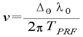
여기서, TPRF는 초음파신호를 송신하는 주기 즉, 펄스 반복 주파수(Pulse Repitition Frequency: PRF)의 역수이며, λ0는 송신되는 초음파신호의 중심주파수이고, △θ는 위상의 변화량이다. 수학식 1에서 알 수 있는 바와 같이, 대상체의 이동속도는 대상체에서 반사된 신호의 위상의 변화량에 비례한다. 또한, 신호의 주파수 편이는 위상의 변화량에 비례하므로, 대상체의 이동속도 v는 반사신호의 주파수 편이량에 비례한다. 따라서, 대상체에서 반사된 반사신호의 주파수를 측정하여 대상체의 이동속도를 계산할 수 있다.Here, T PRF is an inverse of the period of transmitting the ultrasonic signal, that is, the pulse repetition frequency (PRF), λ 0 is the center frequency of the transmitted ultrasonic signal, and Δ θ is the amount of phase change. As can be seen in Equation 1, the moving speed of the object is proportional to the amount of change in the phase of the signal reflected from the object. In addition, since the frequency shift of the signal is proportional to the amount of phase change, the moving speed v of the object is proportional to the amount of frequency shift of the reflected signal. Therefore, the moving speed of the object may be calculated by measuring the frequency of the reflected signal reflected from the object.
한편, 인체 내의 혈류의 속도는 일반적으로 혈관의 종류에 따라 다르다. 예를 들어, 경동맥의 혈류의 속도는 100cm/sec 정도이며, 동맥의 혈류의 속도는 50cm/sec 정도이고, 척추동맥의 혈류속도는 35cm/sec 정도이다. 또한, 정맥의 혈류속도는 25cm/sec 정도이며, 모세혈관의 혈류속도는 0.5mm/sec 정도이다.On the other hand, the speed of blood flow in the human body generally depends on the type of blood vessel. For example, the velocity of blood flow in the carotid artery is about 100 cm / sec, the velocity of blood flow in the arteries is about 50 cm / sec, and the velocity of blood flow in the vertebral arteries is about 35 cm / sec. In addition, vein blood flow rate is about 25cm / sec, capillary blood flow rate is about 0.5mm / sec.
따라서, 이동속도계산부(130)는 각각의 혈관의 종류에 대응하는 혈류의 평균속도를 기 설정하여 두고, 계산된 반사지점의 이동속도를 기 설정된 각각의 혈관의 평균 혈류속도와 비교함으로써, 초음파신호의 반사지점이 혈관인 경우에는 해당 혈관의 종류를 판별할 수도 있다.Therefore, the moving
니들방향조절부(140)는 이동속도계산부(130)에 의해 계산된 이동속도가 기 설정된 값 이상이면, 니들의 진행방향을 조절한다. 예를 들어, 니들방향조절부(140)는 척추동맥의 혈류속도에 해당하는 35cm/sec를 진행방향 우회판단의 기준속도로 설정하여 두고, 이동속도계산부(130)에 의해 계산된 반사지점의 대상체의 이동속도가 35cm/sec 이상이면 니들의 진행방향을 우회시킬 수 있다. The needle
도 6은 본 발명의 실시예에 따른 니들 방향조절 장치의 예를 개략적으로 도시한 도면이다. 도 6을 참조하여 도 1의 니들방향조절부(140)를 상세하게 설명한다.6 is a view schematically showing an example of a needle direction control device according to an embodiment of the present invention. The needle
도 6을 참조하면, 니들 방향조절 장치(140)는 니들(141)의 일정길이를 둘러싸는 작업관(143), 작업관(143)의 내면에 니들(141)을 향해 설치된 돌기(145), 작업관(143)의 일정길이를 둘러싸는 외작업관(148), 및 외작업관(148)이 작업관(143)을 따라 왕복운동하여 돌기(145)를 누르도록 제어하는 제어부(149)를 구비할 수 있다. 이때, 작업관(143)은 플렉시블(flexible)한 재질로 형성될 수 있으며, 돌기(145)는 작업관(143)을 관통하는 니들(141)을 향해 볼록할 뿐만 아니라 니들(141)에 의해 지지되어 작업관(143)의 외면을 볼록하게 할 수도 있다. Referring to FIG. 6, the needle
또한, 작업관(143)의 내면에는 돌기(145)와 설정된 간격으로 제2돌기(147)가 설치될 수 있다. 이때, 제2돌기(147)는 도 6에 도시한 바와 같이, 돌기(145)의 방향과 대향하는 방향이 되도록 작업관(143)의 반대측에 설치될 수 있다. 그러나, 제2돌기(147)의 설치위치는 이에 한정되지 않으며, 돌기(145)의 방향과 동일한 방향이 되도록 작업관(143)의 동일측에 설치될 수도 있다.In addition, the
또한, 본 발명의 실시예에 따른 니들 방향조절 장치(140)는 전술한 신호송수신부(120), 이동속도계산부(130) 및 고주파통과필터(150)를 포함하여 구성될 수도 있다.In addition, the needle
이와 같은 구조의 니들 방향조절 장치(140)는 제어부(149)의 제어에 의해 니들(141)이 작업관(143)을 관통하여 왕복운동하게 되며, 그에 따라 니들링 타겟을 향해 진행하여 니들링 동작을 수행한다. 이때, 니들 방향조절 장치(140)는 니들(141)을 따라 가이드 와이어(도시하지 않음)를 니들링 타겟을 향해 삽입할 수 있으며, 해당 가이드 와이어를 이용하여 작업관(143) 및 외작업관(148)을 이동시킬 수도 있다.Needle
도 7은 도 6의 니들 방향조절 장치의 동작을 설명하기 위해 도시한 도면이다. 여기서, 도 7의 (a)는 외작업관(148)이 돌기(145)를 누르는 경우의 예를 나타낸 도면이며, 도 7의 (b)는 외작업관(148)이 돌기(145) 및 제2돌기(147)를 누르는 경우의 예를 나타낸 도면이다.7 is a view for explaining the operation of the needle direction control device of FIG. Here, Figure 7 (a) is a view showing an example when the outer working
니들(141)의 선단에는 신호송수신부(120)가 설치되며, 주기적으로 초음파신호를 송신하고 송신된 초음파신호에 대응하는 반사신호를 수신할 수 있다. 이때, 이동속도계산부(130)는 신호송수신부(120)에 의해 수신된 반사신호에 기초하여 반사지점의 이동속도를 계산한다.A signal transmitting and receiving
이동속도계산부(130)에 의해 계산된 반사지점의 속도가 기 설정된 값 이상이면, 제어부(149)는 외작업관(148)이 니들(141)의 선단을 향하여 진행하도록 제어할 수 있다. 이때, 제어부(149)의 제어에 의해 니들(141)의 선단으로 진행한 외작업관(148)이 돌기(145)를 누르게 되면, 니들(141)은 반대방향으로 밀리지만 제2니들(147)에 의해 지지되기 때문에 도 7의 (a)에 도시한 바와 같은 방향으로 기울어지게 된다. 이와 같이 니들(141)의 방향을 기울임으로써 니들(141)의 선단측에 위치한 혈관을 우회하여 진행할 수 있게 된다.If the velocity of the reflection point calculated by the
외작업관(148)을 니들(141)의 선단측으로 더욱 진행시켜 돌기(145) 및 제2돌기(147)를 모두 누르게 되면, 제2돌기(145)를 지지하는 힘은 외작업관(148)에 의해 더욱 커지므로 니들(141)은 도 7의 (b)에 도시한 바와 같이, 더욱 큰 각도로 기울어지게 된다. 이로써, 니들 방향조절 장치(140)는 니들(141)의 선단 측에 위치한 혈관의 굵기에 따라 니들(141)의 기울여지는 각도를 다르게 조절할 수 있게 된다.When the
도 6 및 도 7에는 돌기(145) 및 제2돌기(147)가 서로 대향하는 방향으로 설치된 경우를 도시하고 설명하였지만, 전술한 바와 같이 돌기 및 제2돌기는 동일한 방향으로 작업관의 동일한 측에 설치될 수도 있다. 이 경우, 제2돌기는 돌기보다 큰 크기로 설치될 수 있으며, 그에 따라 제2돌기가 외작업관에 의해 눌리는 경우에는 니들이 더욱 큰 각도로 기울여지게 할 수도 있다.6 and 7 illustrate the case where the
고주파통과필터(150)는 신호송수신부(120)에 의해 수신되는 반사신호 중 설정된 주파수 이하의 저주파 대역을 차단한다. 혈액 이외의 조직 및 근육은 혈액에 비하여 상대적으로 느리게 움직이기 때문에, 이들로부터 반사되는 반사신호는 주로 저주파 대역에 위치한다. 따라서, 고주파통과필터(150)는 고주파 통과 필터(High Pass Filter)를 이용하여 일정한 주파수 이하의 반사신호를 차단할 수 있다.The high
도 8은 본 발명의 실시예에 따른 수술용 로봇 제어방법을 나타낸 흐름도이다.8 is a flowchart illustrating a surgical robot control method according to an embodiment of the present invention.
도 1 내지 도 8을 참조하면, 니들구동부(110)는 병변 위치에 대응하여 로봇암(200)의 니들링 타겟(Needling Target)을 설정하며(S810), 설정된 니들링 타겟을 향해 로봇암(200)을 이동하여 니들링 동작을 실행시킨다(S820).1 to 8, the
신호송수신부(120)는, 니들구동부(110)에 의해 설정된 니들링 타겟을 향해 주기적으로 초음파신호를 송신하고, 송신된 초음파신호에 대한 반사신호를 수신한다(S830). 이때, 고주파통과필터(150)는 신호송수신부(120)에 의해 수신되는 반사신호 중 설정된 주파수 이하의 저주파 대역을 차단할 수 있다(S840). The signal transmitter /
이동속도계산부(130)는 신호송수신부(120)에 의해 수신된 반사신호에 기초하여 반사지점의 이동속도를 계산한다(S850).The
이동속도계산부(130)에 의해 계산된 반사지점의 이동속도가 기 설정된 값 이상인 경우(S860), 니들방향조절부(140)는 니들(141)의 진행방향을 조절할 수 있다. 이와 같은 니들의 방향조절 방법은 도 9에 도시한 니들 방향조절 방법에 따라 수행될 수 있다.When the moving speed of the reflection point calculated by the moving
즉, 니들구동부(110)에 의해 니들링 타겟 지점으로 이동된 로봇암(200)에 대하여, 제어부(149)는 니들(141)이 작업관(143)을 관통하여 왕복운동하도록 제어하여 니들링 동작을 수행할 수 있다(S910).That is, with respect to the
신호송수신부(120)는 니들(141)의 선단에서 주기적으로 초음파신호를 송신하며(S920), 송신된 초음파신호에 대응하는 반사신호를 수신한다(S930).The signal transmitter /
이때, 고주파통과필터(150)는 신호송수신부(120)에 의해 수신되는 반사신호 중 설정된 주파수 이하의 저주파 대역을 차단할 수 있다(S940). In this case, the high
이동속도계산부(130)는 신호송수신부(120)에 의해 수신된 반사신호에 기초하여 반사지점의 이동속도를 계산한다(S950).The
이동속도계산부(130)에 의해 계산된 반사지점의 이동속도가 기 설정된 값 이상인 경우(S960), 제어부(149)는 외작업관(148)을 니들(141)의 선단을 향해 전진이동시켜 돌기(145)를 니들(141)에 압착시킬 수 있다(S970). 이때, 제어부(149)의 제어에 의해 니들(141)의 선단으로 진행한 외작업관(148)이 돌기(145)를 누르게 되면, 니들(141)은 반대방향으로 밀리지만 제2니들(147)에 의해 지지되기 때문에 돌기(145)가 설치된 방향으로 기울어지게 된다. 이와 같이 니들(141)의 방향을 기울임으로써 니들(141)의 선단측에 위치한 혈관을 우회하여 진행할 수 있게 된다.When the moving speed of the reflection point calculated by the moving
제어부(149)가 외작업관(148)을 니들(141)의 선단측으로 더욱 진행시켜 돌기(145) 및 제2돌기(147)를 모두 누르게 되면, 제2돌기(145)를 지지하는 힘은 외작업관(148)에 의해 커지게 되며, 그에 따라 니들(141)은 더욱 큰 각도로 돌기(145)를 향해 기울어지게 된다. 이로써, 니들 방향조절 장치(140)는 니들(141)의 선단 측에 위치한 혈관의 굵기에 따라 니들(141)의 기울여지는 각도를 더욱 크게 조절할 수 있게 된다.When the
110: 니들구동부 120: 신호송수신부
130: 이동속도계산부 140: 니들방향조절부
141: 니들 143: 작업관
145: 돌기 147: 제2돌기
148: 외작업관 149: 제어부
150: 고주파통과필터 110: needle drive unit 120: signal transmission and reception unit
130: moving speed calculation unit 140: needle direction control unit
141: needle 143: worker
145: projection 147: second projection
148: external worker 149: control unit
150: high frequency pass filter
Claims (12)
병변 위치에 대응하여 로봇암(Robot Arm)의 니들링 타겟(Needling Target)을 설정하며, 설정된 상기 니들링 타겟을 향해 상기 로봇암을 이동하여 니들링 동작을 수행하는 니들구동부;
상기 로봇암의 니들 선단에 설치되며, 상기 니들구동부에 의해 설정된 니들링 타겟을 향해 주기적으로 초음파신호를 송신하고, 송신된 상기 초음파신호에 대한 반사신호를 수신하는 신호송수신부;
상기 신호송수신부에 의해 수신된 반사신호에 기초하여 반사지점의 이동속도를 계산하는 이동속도계산부; 및
상기 이동속도계산부에 의해 계산된 이동속도가 기 설정된 값 이상이면, 상기 니들의 진행방향을 조절하는 니들방향조절부;
를 포함하는 것을 특징으로 하는 수술용 로봇제어 시스템.In the robot control system for surgery,
A needle driver configured to set a needling target of the robot arm in response to the lesion position, and move the robot arm toward the set needing needle to perform a needling operation;
A signal transmitting and receiving unit which is installed at the tip of the needle of the robot arm and periodically transmits an ultrasonic signal toward a needling target set by the needle driver, and receives a reflected signal for the transmitted ultrasonic signal;
A moving speed calculator for calculating a moving speed of a reflection point based on the reflected signal received by the signal transmitting and receiving unit; And
A needle direction control unit which adjusts a moving direction of the needle when the moving speed calculated by the moving speed calculator is greater than or equal to a preset value;
Surgical robot control system comprising a.
상기 신호송수신부에 의해 수신되는 반사신호 중 설정된 주파수 이하의 저주파대역을 차단하는 고주파통과필터;
를 더 포함하는 것을 특징으로 하는 수술용 로봇제어 시스템.The method of claim 1,
A high frequency pass filter for blocking a low frequency band below a set frequency among the reflection signals received by the signal transmitter and receiver;
Surgical robot control system further comprising.
니들의 일정길이를 둘러싸는 작업관;
상기 작업관의 내면에 상기 니들을 향해 설치된 돌기;
상기 작업관의 일정길이를 둘러싸는 외작업관; 및
상기 외작업관이 상기 작업관을 따라 왕복운동 하여 상기 돌기를 누르도록 제어하는 제어부;
를 포함하는 것을 특징으로 하는 수술용 로봇제어 시스템의 니들 방향조절 장치.In the needle control device of the surgical robot control system for adjusting the direction of the surgical needle mounted on the robot arm,
A working tube surrounding a predetermined length of the needle;
A protrusion installed toward the needle on an inner surface of the working pipe;
An external work pipe surrounding a predetermined length of the work pipe; And
A control unit for controlling the external work pipe to reciprocate along the work pipe to press the protrusion;
Needle direction control device for a surgical robot control system comprising a.
상기 작업관의 내면에, 상기 돌기와 설정된 간격으로 설치되는 제2돌기;
를 더 포함하며, 상기 제어부는,
상기 외작업관이 상기 작업관을 따라 상기 돌기, 또는 상기 돌기 및 상기 제2돌기를 누르도록 제어하는 것을 특징으로 하는 수술용 로봇제어 시스템의 니들 방향조절 장치.The method of claim 3,
A second protrusion installed on an inner surface of the working pipe at a predetermined interval with the protrusion;
Further comprising, the control unit,
And the external working pipe is controlled to press the protrusion, or the protrusion and the second protrusion along the working pipe.
상기 돌기의 방향과 대향하는 방향이 되도록 상기 작업관의 반대측에 설치되거나, 동일한 방향이 되도록 상기 작업관의 동일측에 설치되는 것을 특징으로 하는 수술용 로봇제어 시스템의 니들 방향조절 장치.The method of claim 4, wherein the second protrusion,
The needle direction control device of the surgical robot control system, characterized in that installed on the opposite side of the working tube to be the direction opposite to the direction of the projection, or installed on the same side of the working tube to be the same direction.
상기 니들의 선단에 설치되며, 주기적으로 초음파신호를 송신하고 송신된 초음파신호에 대응하는 반사신호를 수신하는 신호송수신부;
를 더 포함하며, 상기 제어부는,
상기 신호송수신부에 의해 수신되는 반사신호에 기초하여 상기 외작업관의 왕복운동 거리를 조절하는 것을 특징으로 하는 수술용 로봇제어 시스템의 니들 방향조절 장치.5. The method of claim 4,
A signal transmission and reception unit which is installed at the tip of the needle and periodically transmits an ultrasonic signal and receives a reflected signal corresponding to the transmitted ultrasonic signal;
Further comprising, the control unit,
Needle direction control device for a surgical robot control system, characterized in that for adjusting the reciprocating movement distance of the outer tube based on the reflection signal received by the signal transmission and reception unit.
상기 니들이 상기 작업관을 관통하여 왕복운동 하도록 제어하는 것을 특징으로 하는 수술용 로봇제어 시스템의 니들 방향조절 장치.The apparatus of claim 3,
The needle direction control device of the surgical robot control system, characterized in that for controlling the needle to reciprocate through the working tube.
병변 위치에 대응하여 로봇암의 니들링 타겟을 설정하는 단계;
설정된 상기 니들링 타겟을 향해 상기 로봇암을 이동하여 니들링 동작을 수행하는 단계;
설정된 상기 니들링 타겟을 향해 주기적으로 초음파신호를 송신하고, 송신된 상기 초음파신호에 대한 반사신호를 수신하는 단계;
상기 반사신호 수신단계에 의해 수신된 반사신호에 기초하여 반사지점의 이동속도를 계산하는 단계; 및
상기 이동속도 계산단계에 의해 계산된 이동속도가 기 설정된 값 이상이면, 상기 니들의 진행방향을 조절하는 단계;
를 포함하는 것을 특징으로 하는 수술용 로봇 제어방법.In the surgical robot control method,
Setting a needling target of the robot arm corresponding to the lesion position;
Moving the robot arm toward the set needling target to perform a needling operation;
Periodically transmitting an ultrasonic signal toward the set needling target, and receiving a reflected signal for the transmitted ultrasonic signal;
Calculating a moving speed of a reflection point based on the reflection signal received by the reflection signal receiving step; And
Adjusting a traveling direction of the needle when the moving speed calculated by the moving speed calculating step is greater than or equal to a preset value;
Surgical robot control method comprising a.
상기 반사신호 수신단계에 의해 수신되는 반사신호 중 설정된 주파수 이하의 저주파대역을 차단하는 단계;
를 더 포함하는 것을 특징으로 하는 수술용 로봇 제어방법.9. The method of claim 8,
Blocking a low frequency band below a set frequency among the reflected signals received by the reflected signal receiving step;
Surgical robot control method comprising a further.
상기 니들의 선단에서 주기적으로 초음파신호를 송신하는 단계;
송신된 상기 초음파신호에 대응하는 반사신호를 수신하는 단계; 및
수신되는 상기 반사신호에 기초하여, 상기 니들의 일정길이를 둘러싸는 작업관의 내면에 일정한 간격으로 설치된 돌기를 상기 니들에 압착시키는 단계;
를 포함하는 것을 특징으로 하는 수술용 로봇제어 시스템의 니들 방향조절 방법.In the needle direction control method of the surgical robot control system for adjusting the direction of the surgical needle mounted on the robot arm,
Periodically transmitting an ultrasonic signal at the tip of the needle;
Receiving a reflected signal corresponding to the transmitted ultrasonic signal; And
Pressing projections on the needles at regular intervals on the inner surface of the working tube surrounding the predetermined length of the needles based on the received reflection signal;
Needle direction control method of a surgical robot control system comprising a.
상기 작업관의 일정길이를 둘러싸는 외작업관을 상기 작업관을 따라 왕복운동하여 상기 돌기를 상기 니들에 압착시키는 것을 특징으로 하는 수술용 로봇제어 시스템의 니들 방향조절 방법.The method of claim 10, wherein the pressing step,
And an external work pipe surrounding the predetermined length of the work pipe by reciprocating along the work pipe to compress the protrusion to the needle.
상기 니들이 상기 작업관을 관통하여 왕복운동 하도록 제어하는 단계;
를 더 포함하는 것을 특징으로 하는 수술용 로봇제어 시스템의 니들 방향조절 방법.
The method of claim 10,
Controlling the needle to reciprocate through the working tube;
Needle direction control method of the surgical robot control system characterized in that it further comprises.
Priority Applications (1)
| Application Number | Priority Date | Filing Date | Title |
|---|---|---|---|
| KR1020120027707A KR101291951B1 (en) | 2012-03-19 | 2012-03-19 | Surgical robot control system and method, and needle direction adjustment apparatus and method thereof |
Applications Claiming Priority (1)
| Application Number | Priority Date | Filing Date | Title |
|---|---|---|---|
| KR1020120027707A KR101291951B1 (en) | 2012-03-19 | 2012-03-19 | Surgical robot control system and method, and needle direction adjustment apparatus and method thereof |
Publications (1)
| Publication Number | Publication Date |
|---|---|
| KR101291951B1 true KR101291951B1 (en) | 2013-08-09 |
Family
ID=49219627
Family Applications (1)
| Application Number | Title | Priority Date | Filing Date |
|---|---|---|---|
| KR1020120027707A Active KR101291951B1 (en) | 2012-03-19 | 2012-03-19 | Surgical robot control system and method, and needle direction adjustment apparatus and method thereof |
Country Status (1)
| Country | Link |
|---|---|
| KR (1) | KR101291951B1 (en) |
Cited By (1)
| Publication number | Priority date | Publication date | Assignee | Title |
|---|---|---|---|---|
| WO2018056606A1 (en) * | 2016-09-23 | 2018-03-29 | 최규동 | Insulin injector capable of dosage measurement using photosensor |
Citations (3)
| Publication number | Priority date | Publication date | Assignee | Title |
|---|---|---|---|---|
| US20060036142A1 (en) | 2004-07-13 | 2006-02-16 | Dexcom, Inc. | Transcutaneous analyte sensor |
| US20080097468A1 (en) | 2006-10-18 | 2008-04-24 | Adams Ronald D | Systems for performing gynecological procedures with closed visualization lumen |
| US20100036245A1 (en) | 2005-12-02 | 2010-02-11 | Yan Yu | Image-guided therapy delivery and diagnostic needle system |
-
2012
- 2012-03-19 KR KR1020120027707A patent/KR101291951B1/en active Active
Patent Citations (3)
| Publication number | Priority date | Publication date | Assignee | Title |
|---|---|---|---|---|
| US20060036142A1 (en) | 2004-07-13 | 2006-02-16 | Dexcom, Inc. | Transcutaneous analyte sensor |
| US20100036245A1 (en) | 2005-12-02 | 2010-02-11 | Yan Yu | Image-guided therapy delivery and diagnostic needle system |
| US20080097468A1 (en) | 2006-10-18 | 2008-04-24 | Adams Ronald D | Systems for performing gynecological procedures with closed visualization lumen |
Cited By (1)
| Publication number | Priority date | Publication date | Assignee | Title |
|---|---|---|---|---|
| WO2018056606A1 (en) * | 2016-09-23 | 2018-03-29 | 최규동 | Insulin injector capable of dosage measurement using photosensor |
Similar Documents
| Publication | Publication Date | Title |
|---|---|---|
| US20240032776A1 (en) | Precision control systems for tissue visualization and manipulation assemblies | |
| KR102012990B1 (en) | Percutaneous methods for spinal stenosis and foraminal stenosis | |
| US10004610B2 (en) | Non-invasive methods for modifying tissue to facilitate treatment | |
| KR101328103B1 (en) | Method and system for noninvasive cosmetic enhancement | |
| RU2692219C2 (en) | Multipolar synchronous radio-frequency ablation catheter for pulmonary artery | |
| US7918787B2 (en) | Tissue visualization and manipulation systems | |
| EP1933756B1 (en) | Steerable lesion excluding heart implants for congestive heart failure | |
| KR101640424B1 (en) | Image Guided Plaque Ablation | |
| US20150080942A1 (en) | System and Method for Assisted Manual Compression of Blood Vessel | |
| IL186824A (en) | Apparatus for the destruction of adipose tissue | |
| CN108463156A (en) | Optical guidance formula surgery device | |
| WO2011032017A2 (en) | Apparatus and methods for the destruction of adipose tissue | |
| JP2018526162A (en) | Percutaneous system and method for improving epidural access for spinal surgery | |
| EP1996065A2 (en) | Tissue visualization and manipulation systems | |
| EP3609410B1 (en) | Apparatus for increasing cerebral blood flow | |
| CN106999144A (en) | ultrasonic probe with puncture guiding function | |
| CN113041522B (en) | Ultrasonic physiotherapy system | |
| KR101291951B1 (en) | Surgical robot control system and method, and needle direction adjustment apparatus and method thereof | |
| JP2020081869A (en) | Catheter with irrigator and/or aspirator and fiber optic clot analyzer | |
| CN114727878A (en) | Apparatus and method for cooling brain and diagnosing and treating glioblastoma | |
| Endo et al. | Use of actuator-driven pulsed water jet in brain and spinal cord cavernous malformations resection | |
| KR20230050371A (en) | Extraventricular drain probe and ultrasound stylus complex for placement guided by continuous imaging | |
| KR101333868B1 (en) | Surgical Robot Control System and Method therefor | |
| US10117644B2 (en) | Electrophysiological diagnostic catheter especially for obtaining of endomyocardial biopsy of heart tissue | |
| CN112057167A (en) | Ultrasonic navigation method and ultrasonic navigation equipment for vascular surgery |
Legal Events
| Date | Code | Title | Description |
|---|---|---|---|
| A201 | Request for examination | ||
| PA0109 | Patent application |
St.27 status event code: A-0-1-A10-A12-nap-PA0109 |
|
| PA0201 | Request for examination |
St.27 status event code: A-1-2-D10-D11-exm-PA0201 |
|
| E701 | Decision to grant or registration of patent right | ||
| PE0701 | Decision of registration |
St.27 status event code: A-1-2-D10-D22-exm-PE0701 |
|
| GRNT | Written decision to grant | ||
| PR0701 | Registration of establishment |
St.27 status event code: A-2-4-F10-F11-exm-PR0701 |
|
| PR1002 | Payment of registration fee |
St.27 status event code: A-2-2-U10-U11-oth-PR1002 Fee payment year number: 1 |
|
| PG1601 | Publication of registration |
St.27 status event code: A-4-4-Q10-Q13-nap-PG1601 |
|
| PN2301 | Change of applicant |
St.27 status event code: A-5-5-R10-R13-asn-PN2301 St.27 status event code: A-5-5-R10-R11-asn-PN2301 |
|
| FPAY | Annual fee payment |
Payment date: 20160720 Year of fee payment: 4 |
|
| PR1001 | Payment of annual fee |
St.27 status event code: A-4-4-U10-U11-oth-PR1001 Fee payment year number: 4 |
|
| P22-X000 | Classification modified |
St.27 status event code: A-4-4-P10-P22-nap-X000 |
|
| FPAY | Annual fee payment |
Payment date: 20170725 Year of fee payment: 5 |
|
| PR1001 | Payment of annual fee |
St.27 status event code: A-4-4-U10-U11-oth-PR1001 Fee payment year number: 5 |
|
| FPAY | Annual fee payment |
Payment date: 20180516 Year of fee payment: 6 |
|
| PR1001 | Payment of annual fee |
St.27 status event code: A-4-4-U10-U11-oth-PR1001 Fee payment year number: 6 |
|
| PR1001 | Payment of annual fee |
St.27 status event code: A-4-4-U10-U11-oth-PR1001 Fee payment year number: 7 |
|
| PR1001 | Payment of annual fee |
St.27 status event code: A-4-4-U10-U11-oth-PR1001 Fee payment year number: 8 |
|
| PR1001 | Payment of annual fee |
St.27 status event code: A-4-4-U10-U11-oth-PR1001 Fee payment year number: 9 |
|
| PR1001 | Payment of annual fee |
St.27 status event code: A-4-4-U10-U11-oth-PR1001 Fee payment year number: 10 |
|
| PR1001 | Payment of annual fee |
St.27 status event code: A-4-4-U10-U11-oth-PR1001 Fee payment year number: 11 |
|
| PR1001 | Payment of annual fee |
St.27 status event code: A-4-4-U10-U11-oth-PR1001 Fee payment year number: 12 |
|
| P22-X000 | Classification modified |
St.27 status event code: A-4-4-P10-P22-nap-X000 |
|
| P14-X000 | Amendment of ip right document requested |
St.27 status event code: A-5-5-P10-P14-nap-X000 |
|
| PR1001 | Payment of annual fee |
St.27 status event code: A-4-4-U10-U11-oth-PR1001 Fee payment year number: 13 |
|
| U11 | Full renewal or maintenance fee paid |
Free format text: ST27 STATUS EVENT CODE: A-4-4-U10-U11-OTH-PR1001 (AS PROVIDED BY THE NATIONAL OFFICE) Year of fee payment: 13 |