KR101287402B1 - Roof type industrial dust collecting system - Google Patents
Roof type industrial dust collecting system Download PDFInfo
- Publication number
- KR101287402B1 KR101287402B1 KR1020120142748A KR20120142748A KR101287402B1 KR 101287402 B1 KR101287402 B1 KR 101287402B1 KR 1020120142748 A KR1020120142748 A KR 1020120142748A KR 20120142748 A KR20120142748 A KR 20120142748A KR 101287402 B1 KR101287402 B1 KR 101287402B1
- Authority
- KR
- South Korea
- Prior art keywords
- dust
- space
- roof
- dust collecting
- unit
- Prior art date
- Legal status (The legal status is an assumption and is not a legal conclusion. Google has not performed a legal analysis and makes no representation as to the accuracy of the status listed.)
- Active
Links
Images


Classifications
-
- B—PERFORMING OPERATIONS; TRANSPORTING
- B01—PHYSICAL OR CHEMICAL PROCESSES OR APPARATUS IN GENERAL
- B01D—SEPARATION
- B01D46/00—Filters or filtering processes specially modified for separating dispersed particles from gases or vapours
- B01D46/42—Auxiliary equipment or operation thereof
-
- B—PERFORMING OPERATIONS; TRANSPORTING
- B01—PHYSICAL OR CHEMICAL PROCESSES OR APPARATUS IN GENERAL
- B01D—SEPARATION
- B01D46/00—Filters or filtering processes specially modified for separating dispersed particles from gases or vapours
- B01D46/0084—Filters or filtering processes specially modified for separating dispersed particles from gases or vapours provided with safety means
- B01D46/0086—Filter condition indicators
-
- B—PERFORMING OPERATIONS; TRANSPORTING
- B01—PHYSICAL OR CHEMICAL PROCESSES OR APPARATUS IN GENERAL
- B01D—SEPARATION
- B01D46/00—Filters or filtering processes specially modified for separating dispersed particles from gases or vapours
- B01D46/24—Particle separators, e.g. dust precipitators, using rigid hollow filter bodies
-
- B—PERFORMING OPERATIONS; TRANSPORTING
- B01—PHYSICAL OR CHEMICAL PROCESSES OR APPARATUS IN GENERAL
- B01D—SEPARATION
- B01D46/00—Filters or filtering processes specially modified for separating dispersed particles from gases or vapours
- B01D46/42—Auxiliary equipment or operation thereof
- B01D46/44—Auxiliary equipment or operation thereof controlling filtration
- B01D46/442—Auxiliary equipment or operation thereof controlling filtration by measuring the concentration of particles
-
- B—PERFORMING OPERATIONS; TRANSPORTING
- B01—PHYSICAL OR CHEMICAL PROCESSES OR APPARATUS IN GENERAL
- B01D—SEPARATION
- B01D46/00—Filters or filtering processes specially modified for separating dispersed particles from gases or vapours
- B01D46/42—Auxiliary equipment or operation thereof
- B01D46/44—Auxiliary equipment or operation thereof controlling filtration
- B01D46/446—Auxiliary equipment or operation thereof controlling filtration by pressure measuring
-
- Y—GENERAL TAGGING OF NEW TECHNOLOGICAL DEVELOPMENTS; GENERAL TAGGING OF CROSS-SECTIONAL TECHNOLOGIES SPANNING OVER SEVERAL SECTIONS OF THE IPC; TECHNICAL SUBJECTS COVERED BY FORMER USPC CROSS-REFERENCE ART COLLECTIONS [XRACs] AND DIGESTS
- Y02—TECHNOLOGIES OR APPLICATIONS FOR MITIGATION OR ADAPTATION AGAINST CLIMATE CHANGE
- Y02A—TECHNOLOGIES FOR ADAPTATION TO CLIMATE CHANGE
- Y02A50/00—TECHNOLOGIES FOR ADAPTATION TO CLIMATE CHANGE in human health protection, e.g. against extreme weather
- Y02A50/20—Air quality improvement or preservation, e.g. vehicle emission control or emission reduction by using catalytic converters
- Y02A50/2351—Atmospheric particulate matter [PM], e.g. carbon smoke microparticles, smog, aerosol particles, dust
Landscapes
- Chemical & Material Sciences (AREA)
- Chemical Kinetics & Catalysis (AREA)
- Filtering Of Dispersed Particles In Gases (AREA)
Abstract
본 발명의 특징에 따르면, 내부공간이 마련된 박스형상으로 형성되고, 하부에는 분진(D)이 포함된 오염공기가 유입되는 유입구(111)가 형성되며 상부에는 상기 분진(D)이 여과된 정화공기가 배출되는 배출구(112)가 형성되되, 상기 유입구(111)가 산업용 건물(10)의 지붕(11)에 형성된 유입공(12)과 연통되도록 상기 지붕(11)의 상부에 고정 설치되는 하우징(110)과, 상기 내부공간을 분진(D)이 여과되는 공간인 여과공간부(121)와 정화공기가 배출되는 공간인 배기공간부(122)로 구획하도록 상기 하우징(110)의 내부에 설치되며, 중앙에는 상기 여과공간부(121)와 배기공간부(122)를 상호 연통시키는 흡입공(123)이 형성된 격벽(120)과, 상기 여과공간부(121) 내에 배치되며 상기 유입구(111)를 통해 유입되는 오염공기의 분진(D)을 여과시키는 분진필터부(130) 및, 상기 배기공간부(122) 내에서 상기 흡입공(123)의 상부에 배치되어 회전모터(141)의 구동력에 의해 회전하면서 상기 흡입공(123)을 통해 상기 여과공간부(121) 내의 여과된 정화공기를 상기 배기공간부(122)로 흡입하는 흡입날개부(140)를 포함하는 복수 개의 집진유닛(100);을 포함하며, 상기 복수 개의 집진유닛(100)은 상기 산업용 건물(10)의 지붕(11) 상에서 일정간격으로 이격되어 배치되는 지붕형 산업용 집진시스템이 개시된다.According to a feature of the present invention, the inner space is formed in a box shape, the lower portion is formed with an inlet 111 through which the contaminated air containing the dust (D) is introduced, the upper part of the purified air filtered the dust (D) The discharge port 112 is formed is discharged, the inlet 111 is fixed to the upper portion of the roof 11 so as to communicate with the inlet hole 12 formed in the roof 11 of the industrial building (10) 110 is installed inside the housing 110 so as to divide the internal space into a filtration space 121 that is a space where dust D is filtered and an exhaust space 122 that is a space through which purified air is discharged. And a partition wall 120 having a suction hole 123 communicating with the filtration space 121 and the exhaust space 122 at the center thereof, and disposed in the filtration space 121 to open the inlet 111. Dust filter unit 130 for filtering the dust (D) of contaminated air introduced through, and the exhaust space The purified air in the filtration space 121 is exhausted through the suction hole 123 while being disposed above the suction hole 123 and rotating by the driving force of the rotary motor 141. And a plurality of dust collecting units 100 including suction wing portions 140 suctioned into the space portion 122, wherein the plurality of dust collecting units 100 are disposed on the roof 11 of the industrial building 10. Disclosed is a roof type industrial dust collecting system spaced at regular intervals.
Description
본 발명은 지붕형 산업용 집진시스템에 관한 것으로, 보다 상세하게는 제품 생산 및 가공공장 등의 산업용 건물에 설치되어 생산활동에 따라 필연적으로 발생되는 분진을 외부로 여과하여 내부공기를 정화하며, 건물의 지붕 상에 복수 개의 집진유닛이 일정간격으로 이격 배치되면서 집진기능이 발휘되어 집진시스템의 제조비용 및 설치비용을 최소화한 지붕형 산업용 집진시스템에 관한 것이다.
The present invention relates to a roof type industrial dust collection system, and more particularly, is installed in an industrial building such as a product production and processing plant to purify the internal air by filtration of dust inevitably generated according to production activities to the outside, the roof of the building The present invention relates to a roof type industrial dust collecting system in which a plurality of dust collecting units are spaced at regular intervals and exhibited a dust collecting function to minimize manufacturing and installation costs of a dust collecting system.
일반적으로 제품을 생산, 가공하는 공장 등의 산업용 건물의 경우, 산업활동에 따라 필연적으로 먼지나 가스 등의 이물질을 포함하는 분진이 발생된다. 따라서, 종래의 산업용 건물에는 상기 분진이 포함된 오염공기를 외부로 배출하여 내부공기를 정화할 수 있도록 환기팬 등이 다수 설치되어 운용되었다.In general, industrial buildings, such as factories that produce and process products, inevitably generate dust containing foreign substances such as dust or gas, depending on industrial activities. Therefore, in the conventional industrial building, a plurality of ventilation fans and the like have been installed and used to purify the internal air by discharging the polluted air containing the dust to the outside.
그러나, 최근 환경오염에 대한 대책의 일환으로 대기환경보전법이 개정되어 각 산업용 건물의 업종(시설)에 따라 배출할 수 있는 대기오염물질의 기준농도치가 대폭 낮아지게 되어, 종래에 환기팬으로 내부 공기를 외부로 배출하는 방식의 공기정화 수단은 법적으로 제재가 가해지게 되었다.However, recently, as part of measures to prevent environmental pollution, the Air Environment Conservation Act was amended to significantly reduce the standard concentration level of air pollutants that can be discharged according to the industry (facility) of each industrial building. The air purifying means by which the gas is discharged to outside is legally sanctioned.
여기서, 도 1에는 개정된 대기환경보전법에 부합되도록 개선된 종래의 집진설비의 외부 구성이 개시되어 있다.Here, FIG. 1 discloses an external configuration of a conventional dust collector which is improved to comply with the revised air conservation law.
도 1을 참조하면, 종래의 집진설비는 산업용 건물(10)의 일측에 오염공기에 포함된 분진을 포집할 수 있는 여과수단이 구비된 집진설비(20)를 마련하고, 산업용 건물(10)의 지붕(11) 상부에는 건물 내부의 오염공기가 배출되는 다수 개의 유입공을 형성하며, 상기 유입공을 통해 배출되는 오염공기가 집진설비(20)로 유입되도록 이송하는 다수 개의 덕트관(21)이 구비되었다. 이러한 집진설비(20)는 다수 개의 덕트관(21)으로부터 이송되는 오염공기를 취합하여 하나의 여과수단을 통해 분진(D)을 일괄적으로 필터링하는 방식으로 동작하기 때문에, 산업용 건물(10)의 내부공간의 크기에 비례에 하여 집진설비(20)의 규모가 커질 수 밖에 없었기 때문에 이러한 집진설비(20)를 제조하고 설치하는데 소요되는 비용(공장당 1억 내지 3.5억원)과 대량의 오염공기가 내부로 흡입되도록 흡입모터를 구동하는데에 필요한 전력소모가 과대해지는 문제점이 있었다. Referring to FIG. 1, the conventional dust collecting equipment has a
또한, 지름이 큰 다수 개의 덕트관(21)이 지붕(11)의 상부로부터 지면에 설치된 집진설비(201)에 이르기까지 외부로 노출되기 때문에 미관상 좋지 않을 뿐만 아니라, 우천 및 이물질 등에 의해 상기 덕트관(21)이 쉽게 노후화되면서 유지관리 비용이 증가하게 되며 설비의 수명이 단축되는 문제점이 있었다.In addition, since a large number of
더욱이, 상기 집진설비(20)는 산업용 건물(10)에 근접하여 지면에 배치되기 때문에, 집진설비(20)가 구동하면서 발생되는 진동 및 소음이 건물 외부는 물론 내부로까지 쉽게 전파되어 건물 주변이 시끄러워지는 문제점이 있었다.
In addition, since the
본 발명은 상술한 문제점을 해결하기 위하여 창출된 것으로, 본 발명의 목적은 상대적으로 소형 제작된 복수 개의 집진유닛을 산업용 건물의 지붕에 일정간격으로 이격 배치하여, 요구되는 집진기능은 그대로 구현하면서 집진설비의 제조 및 설치비용을 최소화하며, 소음 발생 및 유지관리 비용을 절감할 수 있는 지붕형 산업용 집진시스템을 제공하는 것에 있다.The present invention was created in order to solve the above problems, an object of the present invention is to arrange a plurality of relatively small dust collection units spaced apart at regular intervals on the roof of an industrial building, dust collection while implementing the required dust collection function as it is It is to provide a roof type industrial dust collection system that can minimize the manufacturing and installation costs of equipment and reduce noise generation and maintenance costs.
또한, 본 발명의 다른 목적은, 각 집진유닛 별로 유입되는 분진량 또는 동작상태에 따라 개별적 또는 통합적으로 복수 개의 집진유닛을 중앙제어할 수 있으며, 상기 동작상태를 관리자가 용이하게 확인할 수 있는 지붕형 산업용 집진시스템을 제공하는 것에 있다.
In addition, another object of the present invention, it is possible to centrally control a plurality of dust collecting units individually or collectively according to the amount of dust or the operating state introduced for each dust collection unit, the roof type industrial dust collector can easily check the operation state To provide a system.
본 발명의 특징에 따르면, 내부공간이 마련된 박스형상으로 형성되고, 하부에는 분진(D)이 포함된 오염공기가 유입되는 유입구(111)가 형성되며 상부에는 상기 분진(D)이 여과된 정화공기가 배출되는 배출구(112)가 형성되되, 상기 유입구(111)가 산업용 건물(10)의 지붕(11)에 형성된 유입공(12)과 연통되도록 상기 지붕(11)의 상부에 고정 설치되는 하우징(110)과, 상기 내부공간을 분진(D)이 여과되는 공간인 여과공간부(121)와 정화공기가 배출되는 공간인 배기공간부(122)로 구획하도록 상기 하우징(110)의 내부에 설치되며, 중앙에는 상기 여과공간부(121)와 배기공간부(122)를 상호 연통시키는 흡입공(123)이 형성된 격벽(120)과, 상기 여과공간부(121) 내에 배치되며 상기 유입구(111)를 통해 유입되는 오염공기의 분진(D)을 여과시키는 분진필터부(130) 및, 상기 배기공간부(122) 내에서 상기 흡입공(123)의 상부에 배치되어 회전모터(141)의 구동력에 의해 회전하면서 상기 흡입공(123)을 통해 상기 여과공간부(121) 내의 여과된 정화공기를 상기 배기공간부(122)로 흡입하는 흡입날개부(140)를 포함하는 복수 개의 집진유닛(100);을 포함하며, 상기 복수 개의 집진유닛(100)은 상기 산업용 건물(10)의 지붕(11) 상에서 일정간격으로 이격되어 배치되는 지붕형 산업용 집진시스템이 개시된다.
According to a feature of the present invention, the inner space is formed in a box shape, the lower portion is formed with an
본 발명의 다른 특징에 따르면, 상부와 하부가 개구된 단관 형상으로 형성되고, 상단 둘레는 수평하게 형성되어 상기 하우징(110)의 하부에 체결되며, 하단 둘레는 각 집진유닛(100)이 설치되는 상기 지붕(11)의 경사면과 대응되는 경사각(θ)으로 경사지게 형성되어 상기 지붕(11) 상에 체결되는 수평설치부(210);가 더 구비되며, 상기 집진유닛(100)은, 상기 수평설치부(210)의 상부에 체결되어 수평상태를 유지한 상태로 상기 지붕(11) 상에서 일정간격으로 이격되어 상기 지붕(11)의 상부에 고정 설치되는 것을 특징으로 하는 지붕형 산업용 집진시스템이 개시된다.
According to another feature of the invention, the upper and lower portions are formed in an open tube shape, the upper circumference is horizontally fastened to the lower portion of the
본 발명의 또 다른 특징에 따르면, 상기 집진유닛(100)에는, 상기 내부공간 내의 분진량을 감지하는 분진감지부(150) 또는 상기 내부공간 내의 압력변화를 감지하는 압력감지부(160) 중의 어느 하나 이상이 장착되며, 상기 지붕형 산업용 집진시스템은, 제어신호에 따라 상기 회전모터(141)에 구동전원을 공급하여 구동제어하는 회전모터 구동부(220);와 상기 분진감지부(150)에 의해 측정된 분진량 또는 상기 압력감지부(160)에 의해 측정된 내부공간 내의 압력 변화에 따라 상기 회전모터(141)의 출력 크기를 능동적으로 제어하기 위한 제어신호를 출력하는 중앙제어부(230); 및 각 집진유닛(100)의 동작상태를 표시하는 표시부(241)와 각 집진유닛(100)의 동작을 선택적으로 설정 및 조작하기 위한 입력수단(242)이 구비된 제어단말(240);을 더 포함하는 것을 특징으로 하는 지붕형 산업용 집진시스템이 개시된다.
According to another feature of the invention, the
이상에서와 같이 본 발명에 의하면, As described above, according to the present invention,
첫째, 산업용 건물에서 요구되는 분진 여과 기준치에 대하여 1/n의 여과성능을 갖도록 설계되어 상대적으로 소형 제작된 복수 개의 집진유닛을 산업용 건물의 지붕 상에 일정간격으로 이격배치함으로써, 요구되는 집진기능은 그대로 구현하면서 집진설비의 제조 및 설치비용을 최소화하며, 집진기능을 구현하기 위해 구동모터를 구동하는데 필요한 전력소모를 상대적으로 절감할 수 있는 효과가 있다.First, by arranging a plurality of relatively small dust collecting units that are designed to have a filtration performance of 1 / n with respect to the dust filtration reference value required in the industrial building spaced at regular intervals on the roof of the industrial building, the required dust collection function is It is possible to minimize the manufacturing and installation costs of the dust collecting facility while realizing it as it is, and to relatively reduce the power consumption required to drive the driving motor to implement the dust collecting function.
둘째, 집진유닛이 산업용 건물의 지붕 상부에 배치되어 구동모터가 동작되면서 발생하는 소음이 지붕 위의 넓은 공간으로 확산되면서, 지면으로 전달되는 소음이 감소되므로 집진유닛의 구동에 의해 건물 주변이 시끄러워지는 문제점을 해결할 수 있다.Second, as the dust collecting unit is placed on the roof of the industrial building and the noise generated by the driving motor is spread to the large space on the roof, the noise transmitted to the ground is reduced, so that the surrounding area becomes noisy by the driving of the dust collecting unit. The problem can be solved.
셋째, 종래의 집진설비와 같이 오염공기가 이송되도록 외부로 노출되는 다수 개의 덕트관이 불필요하므로, 외관이 미려해지고 설치 및 유지관리 비용이 절감되는 효과를 제공한다.Third, since a plurality of duct pipes exposed to the outside to transport the contaminated air as in the conventional dust collector is not necessary, the appearance is beautiful and the installation and maintenance costs are reduced.
넷째, 각 집진유닛이 산업용 건물의 경사진 지붕에 설치됨에 있어서, 하단 둘레가 상기 지붕의 경사면에 대하여 대응하는 경사각으로 경사지게 형성된 수평설치부에 집진유닛의 상부가 체결되면서 상기 지붕 상에 설치되므로, 상기 집진유닛의 제조 및 운반이 용이하며 집진유닛를 지붕에 설치하기 위한 작업이 간소화되는 효과가 있다.Fourth, since each dust collecting unit is installed on the inclined roof of the industrial building, the upper part of the dust collecting unit is installed on the roof while the bottom circumference is fastened to the horizontal installation portion inclined at a corresponding inclination angle with respect to the inclined surface of the roof, It is easy to manufacture and transport the dust collecting unit, and the work for installing the dust collecting unit on the roof is simplified.
다섯째, 각 집진유닛 별로 유입되는 분진량 또는 동작상태에 따라 개별적 또는 통합적으로 복수 개의 집진유닛을 중앙제어할 수 있으며 상기 동작상태를 관리자가 용이하게 확인할 수 있으므로, 상시 구동모터를 정격전압으로 구동시켜야 하는 종래의 방식과 비교하여 소모되는 전력량을 절감할 수 있으며, 관리자에 의한 유지관리가 편리해지는 효과가 있다.Fifth, it is possible to centrally control a plurality of dust collecting units individually or collectively according to the amount of dust or the operating state introduced by each dust collecting unit, and the operation state can be easily checked by the administrator. Compared with the conventional method, it is possible to reduce the amount of power consumed, and the maintenance by the administrator is convenient.
여섯째, 집진유닛 내에서 분진이 여과되는 여과재를 자동으로 털어내는 진동구동 프레임과 탈거된 분진을 하부에서 수거하는 분진서랍을 통해 상기 여과재에 대한 유지관리가 용이해지며 분진 탈거작업이 간소해진다. 또한, 상기 분진서랍에 수거된 분진의 중량을 감지하여 외부로 표시할 수 있으므로, 관리자가 분진의 충만한 경우에만 집진유닛이 설치된 지붕으로 올라가게 되므로 관리자의 편의가 증대된다.Sixth, through the vibration drive frame to automatically shake off the filter medium in which dust is filtered in the dust collecting unit and the dust drawer to collect the collected dust from the bottom, the maintenance of the filter medium is easy and dust removal operation is simplified. In addition, since the weight of the dust collected in the dust drawer can be detected and displayed to the outside, the manager's convenience is increased because the manager goes up to the roof where the dust collecting unit is installed only when the dust is full.
일곱째, 각 집진유닛의 동작상태를 표시하는 표시부와, 각 집진유닛의 동작을 선택적으로 설정 및 조작하기 위한 입력수단이 구비된 제어단말을 통해, 복수 개의 집진유닛을 개별적 또는 통합적으로 중앙제어할 수 있으므로, 지붕형 산업용 집진시스템을 유지 관리하는데 소요되는 시간 및 인력을 절감할 수 있다.
Seventh, the control unit is provided with a display unit for displaying the operation state of each dust collecting unit, and an input means for selectively setting and operating the operation of each dust collecting unit, it is possible to centrally control the plurality of dust collecting units individually or integrally Therefore, it is possible to reduce the time and manpower required to maintain the roof type industrial dust collection system.
도 1은 종래의 집진설비가 산업용 건물에 설치된 외부 구성을 나타낸 사시도,
도 2는 본 발명의 바람직한 제1실시예에 따른 지붕형 산업용 집진시스템이 산업용 건물에 설치된 외부 구성을 나타낸 사시도,
도 3은 본 발명의 바람직한 제1실시예에 따른 집진유닛의 외부 구성을 나타낸 사시도,
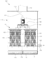
도 4는 본 발명의 바람직한 제1실시예에 따른 집진유닛의 내부 구성을 나타낸 정단면도,
도 5는 본 발명의 바람직한 제1실시예에 따른 집진유닛에 의해 산업용 건물 내부의 오염공기가 정화되는 동작원리를 나타낸 측단면도,
도 6은 본 발명의 바람직한 제1실시예에 따른 집진유닛이 산업용 건물의 지붕 양측에 분할되어 배치된 상태를 나타낸 사시도,
도 7은 본 발명의 바람직한 제2실시예에 따른 집진유닛의 동작원리를 설명하기 위한 블록도,
도 8은 본 발명의 바람직한 제2실시예에 따른 집진유닛의 동작원리를 설명하기 위한 측단면도,
도 9는 본 발명의 바람직한 제2실시예에 따른 제어단말의 구성을 나타낸 개략이다.1 is a perspective view showing the external configuration of a conventional dust collector installed in an industrial building,
2 is a perspective view showing an external configuration in which a roof type industrial dust collecting system according to a first embodiment of the present invention is installed in an industrial building;
3 is a perspective view showing an external configuration of a dust collecting unit according to a first embodiment of the present invention;
Figure 4 is a front sectional view showing the internal configuration of the dust collecting unit according to the first embodiment of the present invention,
Figure 5 is a side cross-sectional view showing the operation principle of the polluted air inside the industrial building by the dust collecting unit according to a first embodiment of the present invention,
6 is a perspective view showing a state in which the dust collecting unit according to the first embodiment of the present invention is dividedly disposed on both sides of the roof of the industrial building,
7 is a block diagram for explaining the operation principle of the dust collecting unit according to a second embodiment of the present invention;
Figure 8 is a side cross-sectional view for explaining the operation principle of the dust collecting unit according to a second embodiment of the present invention,
9 is a schematic diagram showing the configuration of a control terminal according to a second preferred embodiment of the present invention.
상술한 본 발명의 목적, 특징들 및 장점은 다음의 상세한 설명을 통하여 보다 분명해질 것이다. 이하, 본 발명의 바람직한 실시예를 첨부한 도면에 의거하여 설명하면 다음과 같다.The objects, features and advantages of the present invention will become more apparent from the following detailed description. Hereinafter, preferred embodiments of the present invention will be described with reference to the accompanying drawings.
먼저, 도 2 내지 도 6을 참고하여 본 발명의 바람직한 제1실시예에 따른 지붕형 산업용 집진시스템의 구성 및 기능을 설명하기로 한다. 본 발명에 따른 지붕형 산업용 집진시스템은, 산업용 건물(10)에서 요구되는 분진 여과 기준치에 대하여 1/n의 여과성능을 갖도록 설계되어 상대적으로 소형 제작된 복수 개의 집진유닛(100)을 도 2 및 도 6과 같이 산업용 건물(10)의 지붕(11) 상에 일정간격으로 이격배치함으로써, 요구되는 집진기능을 종전과 같이 구현하면서 집진시스템의 제조 및 설치비용을 최소화하며, 집진기능을 구현하기 위한 전력소모를 절감할 수 있는 집진시스템으로서, 복수 개의 집진유닛(100)과 각 집진유닛(100)을 산업용 건물(10)의 지붕(11) 상에 고정 설치하기 위한 수평설치부(210)를 포함한다.First, the configuration and function of the roof type industrial dust collecting system according to the first embodiment of the present invention will be described with reference to FIGS. 2 to 6. The roof type industrial dust collecting system according to the present invention is designed to have a filtration performance of 1 / n with respect to the dust filtration reference value required in the
여기서, 상기 집진유닛(100)은 도 3 내지 5에 도시된 바와 같이, 하우징(110), 격벽(120), 분진필터부(130) 및, 흡입날개부(140)를 포함하여 구비된다.Here, the
상기 하우징(110)은, 본 발명의 바람직한 제1실시예에 따른 집진유닛(100)의 외관을 형성하는 구성으로서, 내부공간이 마련된 박스형상으로 형성되고, 하부에는 분진(D)이 포함된 오염공기가 유입되는 유입구(111)가 형성되며, 상부에는 분진필터부(130)을 통해 분진(D)이 여과된 정화공기가 배출되는 배출구(112)가 형성되되, 상기 유입구(111)가 산업용 건물(10)의 지붕(11)에 형성된 유입공(12)과 연통되도록 상기 지붕(11)의 상부에 고정 설치된다. 여기서, 상기 하우징(110)의 외부에는 상기 내부공간 내의 측정된 압력을 표시하는 압력게이지(115)가 장착될 수 있으며, 상기 압력게이지(115)를 통해 표시되는 압력변화를 통해 분진필터부(130)에 흡착된 분진(D)의 흡착량을 추정할 수 있다.The
또한, 도 3에 도시된 바와 같이, 상기 하우징(110)의 상부에는 일정길이로 연장된 형태로 수직배치되며 일단은 상기 배출구(112)에 연통되어 하우징(110)에 체결되는 배출관(113)이 배치되며, 상기 배출관(113)의 타단에는 배출관(113)의 내부로 빗물이나 이물질이 유입되지 않도록 측부는 개구하면서 상부를 커버하는 배출관커버(114)가 구비되는 것이 바람직하다. 이러한 배출관(113)을 통해 정화공기를 보다 높은 곳에서 외부로 배출할 수 있으므로, 정화된 공기에 필터링되지 않은 미세 분진이 산업용 건물(10)의 주변으로 확산되는 것을 최소화할 수 있다.In addition, as shown in Figure 3, the upper portion of the
상기 격벽(120)은, 상기 하우징(110)의 내부공간을 분진(D)이 여과되는 공간인 여과공간부(121)와 정화공기가 배출되는 공간인 배기공간부(122)로 구획되도록 상기 하우징(110)의 내부에 수평방향으로 설치되는 구성으로서, 중앙에는 여과공간부(121)와 배기공간부(122)를 상호 연통시키기 위한 흡입공(123)이 형성된다.The
상기 분진필터부(130)는, 여과공간부(121) 내에 배치되며 상기 유입구(111)를 통해 유입되는 분진(D)을 흡착하여 여과시키는 구성으로서, 도 4에 도시된 바와 같이, 상기 여과공간부(121) 내에서 상부가 고정된 상태로 수직 배치되는 여과재(131)와, 수평방향으로의 왕복회전하며 진동을 발생시키는 진동모터(132)와, 상기 여과재(131)의 하부에 체결되며 진동모터(132)의 구동력에 의해 수평방향으로 진동동작하여 상기 여과재(131)에 흡착된 분진(D)을 털어내는 진동구동 프레임(133)을 포함하여 구비된다. 여기서, 상기 진동구동 프레임(133)은 여과재(131)의 하부 전체에 수평방향으로 관통체결된 프레임으로서, 상기 진동모터(132)의 회전축(134)에 체결된 링크부재(135)에 단부가 체결되어 상기 진동모터(132)의 구동력을 전달받아 여과재(131)의 하부를 수평방향으로 흔드는 동작을 수행하게 된다.The
또한, 상기 집진유닛(100)에는 도 4 및 도 5에 도시된 바와 같이 여과공간부(121)의 하부에 위치하여 여과재(131)에서 탈거된 분진(D)을 수거하며 외부로 탈착가능하게 하우징(110)에 체결되는 분진서랍(170)이 구비될 수 있다. 이러한 분진서랍(170)의 구성을 통해 수거된 분진(D)의 회수 및 처리가 보다 쉬워진다. 그리고, 상기 여과공간부(121) 내에는 분진서랍(170)이 탈거될 수 있도록 분진서랍(170)의 둘레를 지지하여 가이드함과 동시에, 탈거된 분진(D)이 상기 유입구(111)를 통해 역류하여 지붕(11)의 유입공(12)을 통해 산업용 건물(10)의 내부로 유입되지 않도록 커버하는 분리벽(116: 도 5 참고)이 설치되는 것이 바람직하다.In addition, the
상기 흡입날개부(140)는, 배기공간부(122) 내에서 흡입공(123)의 상부에 배치되어 회전모터(141)의 구동력에 의해 회전하면서 상기 흡입공(123)을 통해 여과공간부(121) 내의 여과된 정화공기를 배기공간부(122)으로 흡입하는 구성으로서, 상기 회전모터(141)는 회전축(미도시)이 하부를 향하도록 배기공간부(122) 내에 고정설치되며, 상기 흡입날개부(140)의 둘레에는 흡입된 정화공기가 측방향으로 배출되도록 기류를 안내하는 가이드프레임(142)이 설치된다.The
한편, 상기 수평설치부(210)는, 도 3 및 도 5에 도시된 바와 같이 상부와 하부가 개구된 단관 형성으로 형성되고, 상단 둘레는 수평하게 형성되어 상기 하우징(110)의 하부에 체결되며, 하단 둘레는 각 집진유닛(100)이 설치되는 지붕(11)의 경사면에 대응되는 격사각(θ)으로 경사지게 형성되어 상기 지붕(11) 상에 체결된다.On the other hand, the
따라서, 상기 집진유닛(100)은 수평설치부(210)의 상부에 체결되어 수평상태를 유지한 상태로 상기 지붕(11) 상에서 일정간격으로 이격되어 지붕(11)의 상부에 고정 설치될 수 있는 것이다. 이러한 수평설치부(210)의 구성을 통해 집진유닛(100)의 하부를 지붕(11)의 경사진 각도에 부합되도록 경사지게 형성하지 않아도 되므로, 집진유닛(100)의 제조 및 운반이 용이하며 집진유닛(100)을 지붕(11)에 설치하기 위한 작업이 간소화되는 효과를 구현할 수 있다.Therefore, the
또한, 상기 집진유닛(100)은 도 2에 도시된 바와 같이 수평설치부(210)에 의해 지붕(11)의 일측 경사면에만 일렬로 이격되어 배치될 수 있을 뿐만 아니라, 도 6에 도시된 바와 같이 지붕(11)의 양측 경사면에 나뉘어 이격 배치될 수도 있고, 도시되지는 않았으나 지붕(11)의 모서리진 중앙부분에 일렬로 이격 배치될 수도 있다. 그리고, 본 발명의 바람직한 제1실시예에 따른 집진시스템은 지붕(11)에 설치된 집진유닛(100)을 유지관리할 수 있도록 지면에서 지붕(11)으로 연결된 사다리 등의 승강수단(13) 및 상기 각 집진유닛(100)의 주변을 둘러싸는 형태로 설치되는 안전난간(14)이 더 구비될 수도 있다.In addition, the
여기서, 도 5에는 본 발명의 바람직한 제1실시예에 따른 산업용 건물(10)의 지붕(11)에 형성된 유입공(12)을 통해 유입되는 오염공기가 집진유닛(100)을 정화되는 동작원리가 도시되어 있다. 도 5의 화살표 표시는 오염공기 또는 정화공기의 기류를 나타낸다.Here, FIG. 5 illustrates an operation principle of purifying the
도 5를 참고하면, 상기 회전모터(141)의 구동력에 의해 흡입날개부(140)가 회전하여 여과공간부(121) 내에서 흡입공(123)을 통해 흡입되는 공기의 기류가 발생하게 되면, 공기의 압력변화에 따라 지붕(11)의 유입공(12)을 통해 산업용 건물(10)의 실내공기가 유입구(111)로 유입되는 기류가 발생하게 되며, 이 기류는 상기 흡입공(123)을 통해 흡입되는 기류에 의해 분진필터부(130)의 여과재(131)를 거치면서 공기에 포함된 분진(D)이 여과된 상태로 상기 흡입공(123)으로 흡입된다. 또한, 흡입공(123)으로 흡입된 공기의 기류는 가이드프레임(142)에 의해 안내되어 측방향으로 배출된 후 배기공간부(122)에서 배출관(113)으로 유입되어 외부로 배출된다.Referring to FIG. 5, when the
상술한 바와 같은 본 발명의 바람직한 제1실시예에 따른 집진시스템의 각 구성 및 기능에 의해, 산업용 건물(10)에서 요구되는 분진 여과 기준치에 대하여 1/n의 여과성능을 갖도록 설계되어 상대적으로 소형 제작된 복수 개의 집진유닛(100)을 산업용 건물(10)의 지붕 상에 일정간격으로 이격배치함으로써, 요구되는 집진기능은 그대로 구현하면서 집진설비의 제조 및 설치비용을 최소화하며, 집진기능을 구현하기 위해 회전모터(141)를 구동하는데 필요한 전력소모를 상대적으로 절감할 수 있는 효과가 있다.Each configuration and function of the dust collecting system according to the first preferred embodiment of the present invention as described above is designed to have a filtration performance of 1 / n relative to the dust filtration reference value required in the
또한, 집진유닛(100)이 산업용 건물(10)의 지붕(11) 상부에 배치되어 회전모터(141)가 동작되면서 발생하는 소음이 상기 지붕(11) 상의 넓은 공간으로 확산되면서, 지면으로 전달되는 소음이 감소되므로 건물 주변이 시끄러워지는 문제점을 해결할 수 있으며, 종래의 집진설비와 같이 오염공기가 이송되도록 외부로 노출되는 다수 개의 덕트관(21)이 불필요하므로, 외관이 미려해지고 설치 및 유지관리 비용이 절감되는 효과를 구현할 수 있다.
In addition, the
다음으로는 도 7 내지 도 9를 참조하여 본 발명의 바람직한 제2실시예에 따른 집진시스템의 구성 및 기능을 설명하기로 한다.Next, the configuration and function of the dust collecting system according to the second preferred embodiment of the present invention will be described with reference to FIGS. 7 to 9.
본 발명의 바람직한 제2실시예에 따른 집진시스템은, 상술한 본 발명의 바람직한 제1실시예에 따른 집진시스템의 전체적인 구성을 모두 포함하며, 지붕(11)에 이격 배치된 복수 개의 집진유닛(100)을 중앙제어하기 위한 분진감지부(150), 압력감지부(160), 회전모터 구동부(220), 중앙제어부(230), 제어단말(240), 분진중량 감지부(180), 진동모터 구동부(250) 등을 더 포함한다는 점에서 차이가 있으므로, 상기 제1실시예에 중복되는 구성에 대한 구체적인 설명은 생략하기로 한다.The dust collecting system according to the second preferred embodiment of the present invention includes the entire configuration of the dust collecting system according to the first preferred embodiment of the present invention described above, and is provided with a plurality of
본 발명의 바람직한 제2실시예에 따른 집진유닛(100)에는 상기 내부공간 내의 분진량을 감지하는 분진감지부(150) 또는 내부공간 내의 압력변화를 감지하는 압력감지부(160)가 장착될 수 있다.The
또한, 본 발명의 바람직한 제2실시예에 따른 집진시스템에는, 상기 중앙제어부(230)의 제어신호에 따라 회전모터(141)에 구동전원을 공급하여 구동제어하는 회전모터 구동부(220)와, 상기 분진감지부(150)에 의해 측정된 분진량 또는 내부공간 내의 압력 변화에 따라 회전모터(141)의 출력 크기를 능동적으로 제어하기 위한 제어신호를 출력하는 중앙제어부(230) 및, 각 집진유닛(100)의 동작상태를 표시하는 표시부(241)와 각 집진유닛(100)의 동작을 선택적으로 설정 및 조작하기 위한 입력수단(242)이 구비된 제어단말(240)이 구비된다.In addition, the dust collecting system according to the second embodiment of the present invention, the rotary
여기서, 상기 분진감지부(150)는 공기에 포함된 분진(D)의 농도를 측정하는 감지센서이며, 압력감지부(160)는 내부공간 내의 압력변화를 측정하는 감지센서로서, 도 8에 도시된 바와 같이 내부공간 내에서 여과공간부(121)에 설치되어 오염공기에 포함된 분진(D)의 농도를 측정하거나 오염공기의 압력을 감지할 수 있으며, 배기공간부(122)에 설치되어 정화공기에 포함된 분진(D)의 농도를 측정하거나 정화공기의 압력을 감지할 수 있도록 구비될 수 있다. 또한, 상기 중앙제어부(230)에는 측정된 압력변화 또는 분진농도 측정량에 따라 회전모터(141)의 출력 크기를 능동적으로 조절하기 위한 기준데이터가 기저장된다. Here, the
따라서, 중앙제어부(230)는 각 감지부(150,160)로부터 감지신호를 전달받아 내부공간 내에서 압력이 증가하거나 분진(D)의 농도가 증가하게 되면, 회전모터(141)의 출력 크기를 증대시켜 여과성능이 향상되도록 제어하며, 상기 압력이 감소하거나 분진(D)의 농도가 감소하게 되면 회전모터(141)의 출력 크기를 감소시켜 여과성능이 상대적으로 약해지도록 제어할 수 있는 것이다.Therefore, the
또한, 상기 집진시스템은 중앙제어부(230)의 제어신호에 따라 상기 진동모터(132)에 구동전원을 공급하여 구동제어하는 진동모터 구동부(250)를 더 포함되어, 입력수단(242)의 조작에 따라 제어단말(240)을 통해 진동구동 프레임(133)에 의한 자동 탈거 작업이 자동적으로 수행되도록 동작시킬 수 있다.In addition, the dust collecting system further includes a vibration
그리고, 상기 집진유닛(100)은 도 8에 도시된 바와 같이 분진서랍(170)에 탈거된 분진(D)의 중량을 감지하는 분진중량 감지부(180)을 더 구비되며, 상기 중앙제어부(230)는 분진중량 감지부(180)에서 측정된 분진(D)의 중량이 표시부(241)를 통해 표시되도록 제어신호를 출력함으로써, 관리자가 제어단말(240)의 표시부(241)를 통해 분진(D)의 중량을 확인함으로써 분진(D)의 충만여부를 용이하게 식별할 수 있다. 이로 인해, 관리자는 분진서랍(170)에 분진(D)이 충만한 경우에만 집진유닛(100)이 설치된 지붕(11)으로 올라가게 되므로 편의가 증대된다.In addition, the
더욱이, 도 9에 도시된 바와 같이, 각 감지부(150,160,180)에서 감지된 정보는 중앙제어부(230)의 제어신호에 따라 표시부(241)에 각 집진유닛(100)별로 표시되므로, 관리자는 각 집진유닛(100)의 동작상태에 따라 입력수단(242)을 조작하여 복수 개의 집진유닛(100)을 개별적 또는 통합적으로 중앙제어할 수 있으므로, 집진시스템을 유지 관리하는데 소요되는 시간 및 인력을 절감할 수 있다.Furthermore, as shown in FIG. 9, the information detected by each of the
이상에서 설명한 본 발명은 전술한 실시예 및 첨부된 도면에 의해 한정되는 것이 아니고, 본 발명의 기술적 사상을 벗어나지 않는 범위 내에서 여러 가지 치환, 변형 및 변경이 가능함은 본 발명이 속하는 기술분야에서 통상의 지식을 가진 자에게 명백할 것이다.
The present invention described above is not limited to the above-described embodiment and the accompanying drawings, and various substitutions, modifications, and changes are possible within the scope without departing from the technical spirit of the present invention. It will be evident to those who have knowledge of.
10...산업용 건물 11...지붕
12...유입공 100...집진유닛
110...하우징 111...유입구
112...배출구 120...격벽
121...여과공간부 122...배기공간부
123...흡입공 130...분진필터부
131...여과재 132...진동모터
133...진동구동 프레임 140...흡입날개부
141...회전모터 150...분진감지부
160...압력감지부 180...분진중량 감지부
210...수평설치부 220...회전모터 구동부
230...중앙제어부 240...제어단말
241...입력수단 242...표시부
250...진동모터 구동부 10 ...
110 ...
112
121
123
131 ... filter 132 ... vibration motor
133
141
160
210.Horizontal mounting section 220.Rotating motor drive section
230 ...
241 input means 242 display
250 ... vibration motor drive
Claims (3)
상기 내부공간을 분진(D)이 여과되는 공간인 여과공간부(121)와 정화공기가 배출되는 공간인 배기공간부(122)로 구획하도록 상기 하우징(110)의 내부에 설치되며, 중앙에는 상기 여과공간부(121)와 배기공간부(122)를 상호 연통시키는 흡입공(123)이 형성된 격벽(120)과,
상기 여과공간부(121) 내에 배치되며 상기 유입구(111)를 통해 유입되는 오염공기의 분진(D)을 여과시키는 분진필터부(130) 및,
상기 배기공간부(122) 내에서 상기 흡입공(123)의 상부에 배치되어 회전모터(141)의 구동력에 의해 회전하면서 상기 흡입공(123)을 통해 상기 여과공간부(121) 내의 여과된 정화공기를 상기 배기공간부(122)로 흡입하는 흡입날개부(140)를 포함하는 복수 개의 집진유닛(100);을 포함하며,
상기 복수 개의 집진유닛(100)은 상기 산업용 건물(10)의 지붕(11) 상에서 일정간격으로 이격되어 배치되는 지붕형 산업용 집진시스템.
It is formed in a box shape provided with an inner space, the inlet 111 is formed in the lower inlet for contaminated air containing the dust (D) is formed in the upper outlet 112 for the purge air filtered the dust (D) is discharged Is formed, the inlet 111 and the housing 110 is fixedly installed on the upper portion of the roof 11 so as to communicate with the inlet hole 12 formed in the roof 11 of the industrial building 10,
The inner space is installed inside the housing 110 to partition the inner space into a filtration space 121, which is a space where dust D is filtered, and an exhaust space 122, which is a space through which purge air is discharged. A partition wall 120 having a suction hole 123 for communicating the filtration space 121 and the exhaust space 122 with each other;
A dust filter unit 130 disposed in the filtration space 121 and filtering dust D of the contaminated air introduced through the inlet 111;
Purified and filtered in the filtration space 121 through the suction hole 123 while being disposed above the suction hole 123 in the exhaust space 122 and rotated by the driving force of the rotary motor 141. And a plurality of dust collecting units (100) including a suction wing (140) for sucking air into the exhaust space (122).
The plurality of dust collecting units (100) is a roof type industrial dust collecting system is disposed spaced apart at regular intervals on the roof (11) of the industrial building (10).
상부와 하부가 개구된 단관 형상으로 형성되고, 상단 둘레는 수평하게 형성되어 상기 하우징(110)의 하부에 체결되며, 하단 둘레는 각 집진유닛(100)이 설치되는 상기 지붕(11)의 경사면과 대응되는 경사각(θ)으로 경사지게 형성되어 상기 지붕(11) 상에 체결되는 수평설치부(210);가 더 구비되며,
상기 집진유닛(100)은, 상기 수평설치부(210)의 상부에 체결되어 수평상태를 유지한 상태로 상기 지붕(11) 상에서 일정간격으로 이격되어 상기 지붕(11)의 상부에 고정 설치되는 것을 특징으로 하는 지붕형 산업용 집진시스템.
The method of claim 1,
The upper and lower portions are formed in an open tube shape, and the upper periphery is horizontally fastened to the lower portion of the housing 110, and the lower periphery is the inclined surface of the roof 11 on which each dust collecting unit 100 is installed. It is formed to be inclined at a corresponding inclination angle (θ) is horizontal mounting portion 210 is fastened on the roof 11;
The dust collecting unit 100 is fastened to the upper portion of the horizontal installation portion 210 is spaced at regular intervals on the roof 11 in a state of maintaining a horizontal state that is fixed to the upper portion of the roof 11 Industrial roof type dust collection system.
상기 집진유닛(100)에는, 상기 내부공간 내의 분진량을 감지하는 분진감지부(150) 또는 상기 내부공간 내의 압력변화를 감지하는 압력감지부(160) 중의 어느 하나 이상이 장착되며,
상기 지붕형 산업용 집진시스템은, 제어신호에 따라 상기 회전모터(141)에 구동전원을 공급하여 구동제어하는 회전모터 구동부(220);와 상기 분진감지부(150)에 의해 측정된 분진량 또는 상기 압력감지부(160)에 의해 측정된 내부공간 내의 압력 변화에 따라 상기 회전모터(141)의 출력 크기를 능동적으로 제어하기 위한 제어신호를 출력하는 중앙제어부(230); 및 각 집진유닛(100)의 동작상태를 표시하는 표시부(241)와 각 집진유닛(100)의 동작을 선택적으로 설정 및 조작하기 위한 입력수단(242)이 구비된 제어단말(240);을 더 포함하는 것을 특징으로 하는 지붕형 산업용 집진시스템.The method of claim 2,
The dust collecting unit 100 is equipped with any one or more of the dust detection unit 150 for detecting the amount of dust in the internal space or the pressure detection unit 160 for detecting a pressure change in the internal space,
The roof type industrial dust collecting system includes: a rotary motor driver 220 for controlling driving by supplying driving power to the rotary motor 141 according to a control signal; and the dust amount or the pressure sensing measured by the dust detector 150. A central controller 230 for outputting a control signal for actively controlling the output size of the rotary motor 141 according to the pressure change in the internal space measured by the unit 160; And a control terminal 240 including a display unit 241 for displaying an operation state of each dust collecting unit 100 and an input means 242 for selectively setting and operating an operation of each dust collecting unit 100. Roof type industrial dust collection system comprising a.
Priority Applications (1)
| Application Number | Priority Date | Filing Date | Title |
|---|---|---|---|
| KR1020120142748A KR101287402B1 (en) | 2012-12-10 | 2012-12-10 | Roof type industrial dust collecting system |
Applications Claiming Priority (1)
| Application Number | Priority Date | Filing Date | Title |
|---|---|---|---|
| KR1020120142748A KR101287402B1 (en) | 2012-12-10 | 2012-12-10 | Roof type industrial dust collecting system |
Publications (1)
| Publication Number | Publication Date |
|---|---|
| KR101287402B1 true KR101287402B1 (en) | 2013-07-19 |
Family
ID=48997630
Family Applications (1)
| Application Number | Title | Priority Date | Filing Date |
|---|---|---|---|
| KR1020120142748A Active KR101287402B1 (en) | 2012-12-10 | 2012-12-10 | Roof type industrial dust collecting system |
Country Status (1)
| Country | Link |
|---|---|
| KR (1) | KR101287402B1 (en) |
Cited By (4)
| Publication number | Priority date | Publication date | Assignee | Title |
|---|---|---|---|---|
| CN108525410A (en) * | 2018-06-11 | 2018-09-14 | 秦皇岛市桑格电气控制设备有限公司 | A kind of devices and methods therefor for collecting cloud |
| KR101897035B1 (en) | 2018-07-12 | 2018-10-18 | 주식회사 마이크로원 | Indoor structure of solid fuel storehouse for enhancing dust-filtering performance |
| KR101897034B1 (en) | 2018-07-12 | 2018-10-18 | 주식회사 마이크로원 | System for improving dust collecting environment in raw material storehouse |
| KR101937092B1 (en) | 2018-05-17 | 2019-01-09 | (주) 옥당산업 | Method and apparatus for monitoring the operation of radioactive concrete dust collector for nuclear power plant decommissioning |
Citations (4)
| Publication number | Priority date | Publication date | Assignee | Title |
|---|---|---|---|---|
| JPH0354388U (en) * | 1989-09-28 | 1991-05-27 | ||
| KR20020016227A (en) * | 2000-08-25 | 2002-03-04 | 이구택 | Performance evaluation and diagnosis system of baghouse system |
| KR200331097Y1 (en) | 2003-07-15 | 2003-10-22 | 서현석 | Dust collector and work shelf for one person to change filter |
| KR100949132B1 (en) | 2009-06-30 | 2010-03-25 | 백구엔지니어링(주) | A bad smell discharging system of a barnyard manure factory |
-
2012
- 2012-12-10 KR KR1020120142748A patent/KR101287402B1/en active Active
Patent Citations (4)
| Publication number | Priority date | Publication date | Assignee | Title |
|---|---|---|---|---|
| JPH0354388U (en) * | 1989-09-28 | 1991-05-27 | ||
| KR20020016227A (en) * | 2000-08-25 | 2002-03-04 | 이구택 | Performance evaluation and diagnosis system of baghouse system |
| KR200331097Y1 (en) | 2003-07-15 | 2003-10-22 | 서현석 | Dust collector and work shelf for one person to change filter |
| KR100949132B1 (en) | 2009-06-30 | 2010-03-25 | 백구엔지니어링(주) | A bad smell discharging system of a barnyard manure factory |
Cited By (5)
| Publication number | Priority date | Publication date | Assignee | Title |
|---|---|---|---|---|
| KR101937092B1 (en) | 2018-05-17 | 2019-01-09 | (주) 옥당산업 | Method and apparatus for monitoring the operation of radioactive concrete dust collector for nuclear power plant decommissioning |
| CN108525410A (en) * | 2018-06-11 | 2018-09-14 | 秦皇岛市桑格电气控制设备有限公司 | A kind of devices and methods therefor for collecting cloud |
| CN108525410B (en) * | 2018-06-11 | 2023-10-20 | 秦皇岛市桑格电气控制设备有限公司 | Device and method for collecting dust mist |
| KR101897035B1 (en) | 2018-07-12 | 2018-10-18 | 주식회사 마이크로원 | Indoor structure of solid fuel storehouse for enhancing dust-filtering performance |
| KR101897034B1 (en) | 2018-07-12 | 2018-10-18 | 주식회사 마이크로원 | System for improving dust collecting environment in raw material storehouse |
Similar Documents
| Publication | Publication Date | Title |
|---|---|---|
| KR101287402B1 (en) | Roof type industrial dust collecting system | |
| KR101543839B1 (en) | Roof Type Industrial Dust Filtering System | |
| KR101284893B1 (en) | Subway cabin air purifier | |
| KR102000707B1 (en) | Air purifier for classroom | |
| CN110280100B (en) | Automatic waste gas treatment process suitable for spraying chamber | |
| KR20170002760U (en) | Dust collection apparatus for welding dust | |
| KR20140147553A (en) | Apparatus for collecting particulate in air using vehicle | |
| KR102043352B1 (en) | Air-cleaning and sound-absorbing device equipment for tunnels | |
| CN107076437A (en) | Aeration clearing device | |
| KR20190026135A (en) | Air purifier of Wall mounting type | |
| KR102290375B1 (en) | Slim standing type air purifier for subway platform | |
| CN115013916A (en) | Factory building air purification treatment system and air purification treatment method | |
| CN114217026A (en) | Pollutant extraction and detection device for atmospheric pollution treatment | |
| KR20190138913A (en) | Air purifier for subway platform | |
| KR102331259B1 (en) | Measuring Device of Fine Particles | |
| CN202715322U (en) | Oil mist filtering machine with filter screen oil stain accumulation detecting device | |
| CN207317120U (en) | One kind removes haze air purifier | |
| CN206018818U (en) | Tobacco workshop air cleaning system | |
| KR20210024817A (en) | Air purifier suitable for mandatory ventilation | |
| KR101877911B1 (en) | Multi air cleaning system | |
| JPH01254225A (en) | Air cleaning apparatus as well as air pollution determining apparatus and filter clogging detector therefor | |
| KR101195757B1 (en) | Apparatus for measuring gas in the air | |
| CN215066445U (en) | Movable public place air detection equipment | |
| CN202303751U (en) | Ventilation device of warehouse | |
| CN106287954A (en) | A kind of air cleaning dust pelletizing system being exclusively used in tobacco workshop |
Legal Events
| Date | Code | Title | Description |
|---|---|---|---|
| A201 | Request for examination | ||
| PA0109 | Patent application |
Patent event code: PA01091R01D Comment text: Patent Application Patent event date: 20121210 |
|
| PA0201 | Request for examination | ||
| A302 | Request for accelerated examination | ||
| PA0302 | Request for accelerated examination |
Patent event date: 20121214 Patent event code: PA03022R01D Comment text: Request for Accelerated Examination Patent event date: 20121210 Patent event code: PA03021R01I Comment text: Patent Application |
|
| E701 | Decision to grant or registration of patent right | ||
| PE0701 | Decision of registration |
Patent event code: PE07011S01D Comment text: Decision to Grant Registration Patent event date: 20130103 |
|
| GRNT | Written decision to grant | ||
| PR0701 | Registration of establishment |
Comment text: Registration of Establishment Patent event date: 20130712 Patent event code: PR07011E01D |
|
| PR1002 | Payment of registration fee |
Payment date: 20130712 End annual number: 3 Start annual number: 1 |
|
| PG1601 | Publication of registration | ||
| FPAY | Annual fee payment |
Payment date: 20160512 Year of fee payment: 4 |
|
| PR1001 | Payment of annual fee |
Payment date: 20160512 Start annual number: 4 End annual number: 4 |
|
| FPAY | Annual fee payment |
Payment date: 20170524 Year of fee payment: 5 |
|
| PR1001 | Payment of annual fee |
Payment date: 20170524 Start annual number: 5 End annual number: 5 |
|
| FPAY | Annual fee payment |
Payment date: 20180531 Year of fee payment: 6 |
|
| PR1001 | Payment of annual fee |
Payment date: 20180531 Start annual number: 6 End annual number: 6 |
|
| FPAY | Annual fee payment |
Payment date: 20190515 Year of fee payment: 7 |
|
| PR1001 | Payment of annual fee |
Payment date: 20190515 Start annual number: 7 End annual number: 7 |
|
| PR1001 | Payment of annual fee |
Payment date: 20200618 Start annual number: 8 End annual number: 8 |
|
| PR1001 | Payment of annual fee |
Payment date: 20210526 Start annual number: 9 End annual number: 9 |
|
| PR1001 | Payment of annual fee |
Payment date: 20220602 Start annual number: 10 End annual number: 10 |
|
| PR1001 | Payment of annual fee |
Payment date: 20230704 Start annual number: 11 End annual number: 11 |
|
| PR1001 | Payment of annual fee |
Payment date: 20240702 Start annual number: 12 End annual number: 12 |
|
| PR1001 | Payment of annual fee |
Payment date: 20250703 Start annual number: 13 End annual number: 13 |