KR101276804B1 - Digital broadcasting system and processing method - Google Patents
Digital broadcasting system and processing method Download PDFInfo
- Publication number
- KR101276804B1 KR101276804B1 KR1020060063877A KR20060063877A KR101276804B1 KR 101276804 B1 KR101276804 B1 KR 101276804B1 KR 1020060063877 A KR1020060063877 A KR 1020060063877A KR 20060063877 A KR20060063877 A KR 20060063877A KR 101276804 B1 KR101276804 B1 KR 101276804B1
- Authority
- KR
- South Korea
- Prior art keywords
- data
- enhanced
- delete delete
- known data
- frequency offset
- Prior art date
- Legal status (The legal status is an assumption and is not a legal conclusion. Google has not performed a legal analysis and makes no representation as to the accuracy of the status listed.)
- Expired - Fee Related
Links
Images


Classifications
-
- H—ELECTRICITY
- H04—ELECTRIC COMMUNICATION TECHNIQUE
- H04B—TRANSMISSION
- H04B1/00—Details of transmission systems, not covered by a single one of groups H04B3/00 - H04B13/00; Details of transmission systems not characterised by the medium used for transmission
- H04B1/06—Receivers
- H04B1/10—Means associated with receiver for limiting or suppressing noise or interference
-
- H—ELECTRICITY
- H03—ELECTRONIC CIRCUITRY
- H03M—CODING; DECODING; CODE CONVERSION IN GENERAL
- H03M13/00—Coding, decoding or code conversion, for error detection or error correction; Coding theory basic assumptions; Coding bounds; Error probability evaluation methods; Channel models; Simulation or testing of codes
- H03M13/25—Error detection or forward error correction by signal space coding, i.e. adding redundancy in the signal constellation, e.g. Trellis Coded Modulation [TCM]
- H03M13/256—Error detection or forward error correction by signal space coding, i.e. adding redundancy in the signal constellation, e.g. Trellis Coded Modulation [TCM] with trellis coding, e.g. with convolutional codes and TCM
-
- H—ELECTRICITY
- H04—ELECTRIC COMMUNICATION TECHNIQUE
- H04L—TRANSMISSION OF DIGITAL INFORMATION, e.g. TELEGRAPHIC COMMUNICATION
- H04L27/00—Modulated-carrier systems
- H04L27/02—Amplitude-modulated carrier systems, e.g. using on-off keying; Single sideband or vestigial sideband modulation
- H04L27/06—Demodulator circuits; Receiver circuits
- H04L27/066—Carrier recovery circuits
-
- H—ELECTRICITY
- H04—ELECTRIC COMMUNICATION TECHNIQUE
- H04N—PICTORIAL COMMUNICATION, e.g. TELEVISION
- H04N19/00—Methods or arrangements for coding, decoding, compressing or decompressing digital video signals
- H04N19/85—Methods or arrangements for coding, decoding, compressing or decompressing digital video signals using pre-processing or post-processing specially adapted for video compression
- H04N19/88—Methods or arrangements for coding, decoding, compressing or decompressing digital video signals using pre-processing or post-processing specially adapted for video compression involving rearrangement of data among different coding units, e.g. shuffling, interleaving, scrambling or permutation of pixel data or permutation of transform coefficient data among different blocks
-
- H—ELECTRICITY
- H04—ELECTRIC COMMUNICATION TECHNIQUE
- H04N—PICTORIAL COMMUNICATION, e.g. TELEVISION
- H04N19/00—Methods or arrangements for coding, decoding, compressing or decompressing digital video signals
- H04N19/85—Methods or arrangements for coding, decoding, compressing or decompressing digital video signals using pre-processing or post-processing specially adapted for video compression
- H04N19/89—Methods or arrangements for coding, decoding, compressing or decompressing digital video signals using pre-processing or post-processing specially adapted for video compression involving methods or arrangements for detection of transmission errors at the decoder
-
- H—ELECTRICITY
- H04—ELECTRIC COMMUNICATION TECHNIQUE
- H04N—PICTORIAL COMMUNICATION, e.g. TELEVISION
- H04N21/00—Selective content distribution, e.g. interactive television or video on demand [VOD]
- H04N21/20—Servers specifically adapted for the distribution of content, e.g. VOD servers; Operations thereof
- H04N21/23—Processing of content or additional data; Elementary server operations; Server middleware
- H04N21/236—Assembling of a multiplex stream, e.g. transport stream, by combining a video stream with other content or additional data, e.g. inserting a URL [Uniform Resource Locator] into a video stream, multiplexing software data into a video stream; Remultiplexing of multiplex streams; Insertion of stuffing bits into the multiplex stream, e.g. to obtain a constant bit-rate; Assembling of a packetised elementary stream
- H04N21/23605—Creation or processing of packetized elementary streams [PES]
Landscapes
- Engineering & Computer Science (AREA)
- Signal Processing (AREA)
- Multimedia (AREA)
- Computer Networks & Wireless Communication (AREA)
- Physics & Mathematics (AREA)
- Probability & Statistics with Applications (AREA)
- Theoretical Computer Science (AREA)
- Error Detection And Correction (AREA)
- Digital Transmission Methods That Use Modulated Carrier Waves (AREA)
Abstract
본 발명은 디지털 방송 시스템과 관련된 것으로서, 특히 본 발명은 송신측에서는 송/수신측의 약속에 의해 정해진 패턴을 갖는 기지 데이터를 송신하고, 수신측에서는 상기 기지 데이터를 이용하여 반송파 복구, 타이밍 복구 뿐만 아니라, 위상 변화의 보상에도 이용함으로써, 채널 변화가 심하거나 노이즈에 약한 환경에서 수신 성능을 향상시킬 수 있다.
부가 데이터, 반송파 복구, 타이밍 복구, 위상
The present invention relates to a digital broadcasting system, and in particular, the present invention transmits known data having a pattern determined by a transmission / receiving party's promise on the transmitting side, and on the receiving side, not only carrier recovery and timing recovery, It is also possible to improve the reception performance in an environment where the channel change is severe or the noise is weak by using the compensation for the phase change.
Side Data, Carrier Recovery, Timing Recovery, Phase
Description
도 1은 본 발명에 따른 디지털 방송 송신 시스템의 일 실시예를 보인 구성 블록도1 is a block diagram showing an embodiment of a digital broadcast transmission system according to the present invention;
도 2는 본 발명의 일 실시예에 따른 데이터 그룹의 구조를 보인 도면2 illustrates a structure of a data group according to an embodiment of the present invention.
도 3은 본 발명에 따른 동일한 패턴의 기지 데이터가 주기적으로 삽입된 예를 보인 도면3 shows an example in which known data of the same pattern is periodically inserted according to the present invention.
도 4는 본 발명에 따른 디지털 방송 수신 시스템의 일 실시예를 보인 구성 블록도Figure 4 is a block diagram showing an embodiment of a digital broadcast receiving system according to the present invention
도 5는 도 4의 복조부의 일 실시예를 보인 구성 블록도FIG. 5 is a block diagram illustrating an embodiment of the demodulator of FIG. 4. FIG.
도 6은 도 4의 기지 데이터 검출 및 초기 주파수 옵셋 추정부의 일 실시예를 보인 구성 블록도FIG. 6 is a block diagram illustrating an embodiment of the known data detection and initial frequency offset estimator of FIG. 4. FIG.
도 7은 도 4의 DC 제거기의 일 실시예를 보인 구성 블록도7 is a block diagram illustrating an embodiment of the DC remover of FIG. 4.
도 8은 도 7의 DC 추정기의 입력 샘플 데이터의 이동 예를 보인 도면8 is a diagram illustrating an example of moving input sample data of the DC estimator of FIG. 7;
<도면의 주요부분에 대한 부호의 설명><Description of the symbols for the main parts of the drawings>
410 : 안테나 420 : 튜너410: antenna 420: tuner
430 : 아날로그/디지탈 컨버터 440 : 복조부430: analog / digital converter 440: demodulator
450 : 기지 데이터 검출 및 초기 주파수 옵셋 추정부450: known data detection and initial frequency offset estimation unit
460 : 등화부 470 : 에러 정정부460: equalizer 470: error correction unit
511 : 위상 분리기 512 : 수치 제어 발진기511: phase separator 512: numerically controlled oscillator
513,515 : 곱셈기 514 : 리샘플러513,515: Multiplier 514: Resampler
516 : 정합 필터 517 : DC 제거기516: matched filter 517: DC eliminator
518 : 데시메이터 520 : 타이밍 복구부518: decimator 520: timing recovery unit
530 : 반송파 복구부 540 : 위상 보상부530: carrier recovery unit 540: phase compensation unit
본 발명은 디지털 방송 시스템에 관한 것으로, 특히 디지털 방송을 송신하고 수신하기 위한 장치 및 방법에 관한 것이다.The present invention relates to a digital broadcasting system, and more particularly, to an apparatus and method for transmitting and receiving digital broadcasting.
디지털 방송 중 북미 및 국내에서 디지털 방송 표준으로 채택된 8T-VSB 전송방식은 MPEG 영상/음향 데이터의 전송을 위해 개발된 시스템이다. 그러나 요즈음 디지털 신호처리 기술이 급속도로 발전하고, 인터넷이 널리 사용됨에 따라서 디지털 가전과 컴퓨터 및 인터넷 등이 하나의 큰 틀에 통합되어 가는 추세이다. 따라서 사용자의 다양한 요구를 충족시키기 위해서는 디지털 방송 채널을 통하여 영상/음향 데이터에 더하여 각종 부가 데이터를 전송할 수 있는 시스템의 개발이 필요하다. The 8T-VSB transmission system, adopted as a digital broadcasting standard in North America and Korea, is a system developed for transmitting MPEG video / audio data. However, with the rapid development of digital signal processing technology and the widespread use of the Internet, digital home appliances, computers, and the Internet are being integrated into one big framework. Therefore, in order to meet various needs of users, it is necessary to develop a system capable of transmitting various additional data in addition to video / audio data through a digital broadcasting channel.
부가 데이터 방송의 일부 이용자는 간단한 형태의 실내 안테나가 부착된 PC 카드 혹은 포터블 기기를 이용하여 부가데이터방송을 사용할 것으로 예측되는데, 실내에서는 벽에 의한 차단과 근접 이동체의 영향으로 신호 세기가 크게 감소하고 반사파로 인한 고스트와 잡음의 영향으로 방송 수신 성능이 떨어지는 경우가 발생할 수 있다. 그런데 일반적인 영상/음향데이터와는 달리 부가 데이터 전송의 경우에는 보다 낮은 오류율을 가져야 한다. 영상/음향 데이터의 경우에는 사람의 눈과 귀가 감지하지 못하는 정도의 오류는 문제가 되지 않는 반면에, 부가데이터(예: 프로그램 실행 파일, 주식 정보 등)의 경우에는 한 비트의 오류가 발생해도 심각한 문제를 일으킬 수 있다. 따라서 채널에서 발생하는 고스트와 잡음에 더 강한 시스템의 개발이 필요하다. Some users of supplementary data broadcasting are expected to use supplementary data broadcasting by using PC card or portable device with simple indoor antenna. In the room, signal strength is greatly reduced due to wall blocking and influence of nearby moving objects. Due to the effects of ghosts and noise caused by reflected waves, broadcast reception performance may deteriorate. However, unlike general video / audio data, the additional data transmission should have a lower error rate. In the case of video / audio data, errors that the human eye and ears cannot detect are not a problem, while in the case of additional data (eg program executables, stock information, etc.), a bit error may cause serious problems. It can cause problems. therefore There is a need to develop a system that is more resistant to ghosting and noise in the channel.
부가 데이터의 전송은 통상 MPEG 영상/음향과 동일한 채널을 통해 시분할 방식으로 이루어 질 것이다. 그런데 디지털 방송이 시작된 이후로 시장에는 이미 MPEG 영상/음향만 수신하는 ATSC VSB 디지털 방송 수신기가 널리 보급되어 있는 상황이다. 따라서 MPEG 영상/음향과 동일한 채널로 전송되는 부가 데이터가 기존에 시장에 보급된 기존 ATSC VSB 전용 수신기에 아무런 영향을 주지 않아야 한다. 이와 같은 상황을 ATSC VSB 호환으로 정의하며, 부가데이터 방송 시스템은 ATSC VSB 시스템과 호환 가능한 시스템이어야 할 것이다. 상기 부가 데이터를 인핸스드 데이터 또는 E-VSB 데이터라 하기도 한다.The transmission of additional data will usually be done in a time division manner over the same channel as the MPEG video / sound. Since the beginning of digital broadcasting, however, ATSC VSB digital broadcasting receivers that receive only MPEG video / audio have been widely used in the market. Therefore, additional data transmitted on the same channel as MPEG video / audio should not affect the existing ATSC VSB-only receivers that have been used in the market. Such a situation is defined as ATSC VSB compatible, and the additional data broadcasting system should be compatible with the ATSC VSB system. The additional data may also be referred to as enhanced data or E-VSB data.
또한 열악한 채널환경에서는 기존의 ATSC VSB 수신 시스템의 수신성능이 떨어질 수 있다. 특히 휴대용 및 이동수신기의 경우에는 채널변화 및 노이즈에 대한 강건성이 더욱 요구된다. In addition, in a poor channel environment, the reception performance of the conventional ATSC VSB receiving system may be degraded. Especially in the case of portable and mobile receivers, robustness against channel changes and noise is required.
따라서 본 발명의 목적은 부가 데이터 전송에 적합하고 노이즈에 강한 새로운 디지털 방송 시스템 및 처리 방법을 제공함에 있다.Accordingly, an object of the present invention is to provide a new digital broadcasting system and processing method suitable for additional data transmission and resistant to noise.
본 발명의 다른 목적은 송/수신측에서 알고 있는 기 정의된 기지 데이터(Known data)를 복조 및 채널 등화에 이용함으로써, 수신 성능을 향상시키는 디지털 방송 시스템 및 처리 방법을 제공하는데 있다.Another object of the present invention is to provide a digital broadcasting system and a processing method for improving reception performance by using predefined known data known to the transmitting / receiving side for demodulation and channel equalization.
상기 목적을 달성하기 위하여, 본 발명에 따른 디지털 방송 수신 시스템은, 수신 데이터로부터 기 정해진 패턴을 갖는 기지 데이터 위치 정보와 초기 주파수 옵셋을 추정하는 기지 데이터 검출 및 초기 주파수 옵셋 추정부; 상기 기지 데이터 위치 정보를 이용하여 수신 데이터로부터 타이밍 에러 정보를 검출하여 타이밍 복구를 수행하는 타이밍 복구부; 상기 초기 주파수 옵셋을 이용하여 초기 동기를 획득하고, 이후 상기 기지 데이터 위치 정보를 이용하여 수신 데이터로부터 주파수 옵셋을 검출하여 반송파 복구를 수행하는 반송파 복구부; 및 상기 기지 데이터 위치 정보를 이용하여 타이밍 복구 및 반송파 복구된 수신 데이터로부터 위상 옵셋을 추정한 후 상기 수신 데이터로부터 위상 옵셋을 보상하는 위상 보상부를 포함하여 구성되는 것을 특징으로 한다.In order to achieve the above object, the digital broadcast reception system according to the present invention includes a known data detection and initial frequency offset estimator for estimating known data position information and an initial frequency offset having a predetermined pattern from the received data; A timing recovery unit detecting timing error information from the received data using the known data position information to perform timing recovery; A carrier recovery unit for acquiring initial synchronization using the initial frequency offset, and then performing carrier recovery by detecting a frequency offset from received data using the known data position information; And a phase compensator for estimating a phase offset from the received data recovered from the timing recovery and carrier recovery using the known data position information, and compensating for the phase offset from the received data.
본 발명에 따른 수신 시스템은, 수신되어 디지털화된 통과대역 데이터를 실수 성분과 허수 성분으로 분리하는 위상 분리기; 상기 위상 분리기의 실수 성분과 허수 성분 데이터에 기 설정된 상수에 해당하는 복소 신호를 곱하여 기저대역으로 천이시키는 제1 곱셈기; 상기 제1 곱셈기에서 출력되는 기저대역 데이터에 상기 타이밍 복구부에서 출력되는 타이밍 에러 정보에 해당하는 복소 신호를 곱하여 상기 기저대역 데이터를 보간하는 리샘플러; 상기 리샘플러의 출력과 반송파 복구부의 출력을 복소곱하여 상기 리샘플러의 출력 데이터에 포함된 주파수 옵셋을 보상하는 제2 곱셈기; 상기 제2 곱셈기의 출력을 정합 필터링하는 정합 필터; 및 상기 정합 필터링전 또는 후 데이터를 입력받아 DC를 추정한 후 상기 데이터에 포함된 DC를 제거하는 DC 제거기를 더 포함하여 구성되는 것을 특징으로 한다.A receiving system according to the present invention comprises: a phase separator for separating received and digitized passband data into a real component and an imaginary component; A first multiplier for multiplying a real signal and an imaginary component data of the phase separator by a complex signal corresponding to a predetermined constant to shift to a baseband; A resampler for interpolating the baseband data by multiplying the baseband data output from the first multiplier by a complex signal corresponding to timing error information output from the timing recovery unit; A second multiplier for compensating the output of the resampler and the output of the carrier recovery unit to compensate for the frequency offset included in the output data of the resampler; A matched filter to match-filter the output of the second multiplier; And a DC remover configured to receive DC before or after the matched filtering to estimate DC and to remove DC included in the data.
본 발명에 따른 디지털 방송 처리 방법은, 수신 데이터로부터 기 정해진 패턴을 갖는 기지 데이터 위치 정보와 초기 주파수 옵셋을 추정하는 단계; 상기 기지 데이터 위치 정보를 이용하여 수신 데이터로부터 타이밍 에러 정보를 검출하여 타이밍 복구를 수행하는 단계; 상기 초기 주파수 옵셋을 이용하여 초기 동기를 획득하고, 이후 상기 기지 데이터 위치 정보를 이용하여 수신 데이터로부터 주파수 옵셋을 검출하여 반송파 복구를 수행하는 단계; 및 상기 기지 데이터 위치 정보를 이용하여 타이밍 복구 및 반송파 복구된 수신 데이터로부터 위상 옵셋을 추정한 후 상기 수신 데이터에 포함된 위상 옵셋을 보상하는 단계를 포함하여 이루어지는 것을 특징으로 한다.In accordance with another aspect of the present invention, there is provided a digital broadcast processing method comprising: estimating known data position information and an initial frequency offset having a predetermined pattern from received data; Detecting timing error information from received data using the known data position information to perform timing recovery; Acquiring initial synchronization using the initial frequency offset, and then detecting a frequency offset from the received data using the known data position information to perform carrier recovery; And estimating a phase offset from the received data recovered from the timing recovery and carrier recovery using the known data position information and compensating for the phase offset included in the received data.
본 발명에 따른 처리 방법은, 수신되어 디지털화된 통과대역 데이터를 실수 성분과 허수 성분으로 분리하는 단계; 상기 분리된 실수 성분과 허수 성분 데이터에 기 설정된 상수에 해당하는 복소 신호를 곱하여 기저대역으로 천이시키는 단계; 상기 단계에서 출력되는 기저대역 데이터에 상기 타이밍 복구 단계에서 출력되는 타이밍 에러 정보에 해당하는 복소 신호를 곱하여 상기 기저대역 데이터를 보간하는 단계; 상기 단계에서 보간된 데이터에 상기 반송파 복구 단계의 복소 데이터를 곱하여 상기 보간 단계의 출력 데이터에 포함된 주파수 옵셋을 보상하는 단계; 상기 주파수 옵셋 보상 단계의 출력 데이터를 정합 필터링하는 단계; 및 상기 정합 필터링전 또는 후 데이터를 입력받아 DC를 추정한 후 상기 데이터에 포함된 DC를 제거하는 단계를 더 포함하여 이루어지는 것을 특징으로 한다.The processing method according to the present invention comprises the steps of: separating received and digitized passband data into a real component and an imaginary component; Transitioning to the baseband by multiplying the separated real component and imaginary component data by a complex signal corresponding to a predetermined constant; Interpolating the baseband data by multiplying the baseband data output in the step by a complex signal corresponding to the timing error information output in the timing recovery step; Compensating a frequency offset included in the output data of the interpolation step by multiplying the data interpolated by the complex data of the carrier recovery step; Matched filtering the output data of the frequency offset compensation step; And estimating a DC by receiving the before or after data of the matched filtering and removing the DC included in the data.
상기 타이밍 복구 단계는 상기 정합 필터링전 또는 후 데이터를 입력받아 버퍼링한 후 상기 기지 데이터 위치 정보에 따라 상기 버퍼링된 기지 데이터 열로부터 타이밍 에러 정보를 검출하는 단계; 상기 검출된 타이밍 에러 정보를 저역 통과 필터링한 후 기지 데이터 열의 주기동안 유지시키는 단계; 및 상기 유지 단계에서 출력되는 타이밍 에러 정보의 저대역 성분에 따라 출력 주파수를 변환시켜 상기 보간 단계의 샘플링 타이밍을 조절하는 단계를 포함하여 이루어지는 것을 특징으로 한다.The timing recovery step may include: detecting timing error information from the buffered known data stream according to the known data position information after receiving and buffering the data before or after the matched filtering; Maintaining the detected timing error information for a period of known data stream after low pass filtering; And adjusting the sampling timing of the interpolation step by converting the output frequency according to the low band component of the timing error information output in the holding step.
상기 반송파 복구 단계는 상기 정합 필터링전 또는 후 데이터를 입력받아 버퍼링한 후 상기 기지 데이터 위치 정보에 따라 상기 버퍼링된 기지 데이터 열로부터 주파수 옵셋을 추정하는 단계; 상기 단계에서 추정된 주파수 옵셋을 저역 통과 필터링한 후 기지 데이터 열의 주기동안 유지시키는 단계; 및 상기 초기 주파수 옵셋과 상기 유지 단계의 주파수 옵셋을 더하여, 그 결과에 해당하는 복소 신호를 생성하여 주파수 옵셋 보상 단계로 출력하는 단계를 포함하여 이루어지는 것을 특징으로 한다.The carrier recovery step may include: estimating a frequency offset from the buffered known data stream according to the known data position information after receiving and buffering the data before or after the matched filtering; Performing low pass filtering on the estimated frequency offset in the step and maintaining it for a period of known data sequences; And adding the initial frequency offset and the frequency offset of the holding step, generating a complex signal corresponding to the result, and outputting the complex signal to the frequency offset compensating step.
상기 위상 보상부는 상기 기지 데이터 위치 정보에 따라 상기 DC가 제거된 기지 데이터 열로부터 주파수 옵셋을 추정하는 단계; 상기 단계에서 추정된 주파수 옵셋을 기지 데이터 열의 주기동안 유지시키는 단계; 및 상기 유지 단계의 주파수 옵셋에 해당하는 복소 신호를 생성한 후 상기 DC가 제거된 데이터와 곱하여 상기 데이터에 포함된 위상 옵셋을 보상하는 단계를 포함하여 이루어지는 것을 특징으로 한다.Estimating a frequency offset from the known data sequence from which the DC is removed according to the known data position information; Maintaining the frequency offset estimated in the step for a period of a known data sequence; And generating a complex signal corresponding to the frequency offset of the sustaining step and multiplying the DC-removed data to compensate for the phase offset included in the data.
상기 DC 제거 단계는 상기 정합 필터링된 데이터의 실수 성분 데이터로부터 DC를 추정하여 상기 실수 성분 데이터에 포함된 DC를 제거하는 단계; 및 상기 정합 필터링된 데이터의 허수 성분 데이터로부터 DC를 추정하여 상기 허수 성분 데이터에 포함된 DC를 제거하는 단계를 포함하여 이루어지는 것을 특징으로 한다.The DC removing step includes estimating DC from real component data of the matched filtered data and removing DC included in the real component data; And estimating DC from the imaginary component data of the matched filtered data to remove the DC included in the imaginary component data.
본 발명의 다른 목적, 특징 및 잇점들은 첨부한 도면을 참조한 실시예들의 상세한 설명을 통해 명백해질 것이다.Other objects, features and advantages of the present invention will become apparent from the following detailed description of embodiments taken in conjunction with the accompanying drawings.
이하 상기의 목적을 구체적으로 실현할 수 있는 본 발명의 바람직한 실시예를 첨부한 도면을 참조하여 설명한다. 이때 도면에 도시되고 또 이것에 의해서 설명되는 본 발명의 구성과 작용은 적어도 하나의 실시예로서 설명되는 것이며, 이것에 의해서 상기한 본 발명의 기술적 사상과 그 핵심 구성 및 작용이 제한되지는 않는다.DETAILED DESCRIPTION OF THE PREFERRED EMBODIMENTS Hereinafter, preferred embodiments of the present invention will be described with reference to the accompanying drawings. At this time, the configuration and operation of the present invention shown in the drawings and described by it will be described as at least one embodiment, by which the technical spirit of the present invention and its core configuration and operation is not limited.
그리고 본 발명에서 사용되는 용어는 가능한 한 현재 널리 사용되는 일반적인 용어를 선택하였으나, 특정한 경우는 출원인이 임의로 선정한 용어도 있으며, 이 경우 해당되는 발명의 설명 부분에서 상세히 그 의미를 기재하였으므로, 단순한 용어의 명칭이 아닌 그 용어가 가지는 의미로서 본 발명을 파악하여야 됨을 밝혀두고자 한다. In addition, the terminology used in the present invention is a general term that is currently widely used as much as possible, but in certain cases, the term is arbitrarily selected by the applicant. In this case, since the meaning is described in detail in the description of the present invention, It is intended that the present invention be understood as the meaning of the term rather than the name.
본 발명에서 인핸스드 데이터는 프로그램 실행 파일, 주식 정보 등과 같이 정보를 갖는 데이터일 수도 있고, 영상/음향 데이터일 수도 있다. 그리고 기지(Known) 데이터는 송/수신측의 약속에 의해 미리 알고 있는 데이터이다. 또한 메인 데이터는 기존의 수신 시스템에서 수신할 수 있는 데이터로서, 영상/음향 데이터를 포함한다. In the present invention, the enhanced data may be data having information such as a program execution file, stock information, or the like, or may be video / audio data. The known data is previously known data by the promise of the transmitting / receiving side. In addition, the main data is data that can be received by the existing receiving system, and includes video / audio data.
즉, 정보를 갖고 있는 인핸스드 데이터를 메인 데이터와 다중화하여 전송하는 디지털 방송 송신 시스템에서는 수신 성능을 향상시키기 위해 송/수신측에서 미리 약속한 패턴을 갖고 있는 기지 데이터도 다중화하여 전송할 수도 있다. That is, in a digital broadcast transmission system that multiplexes and transmits enhanced data having information with main data, it is also possible to multiplex and transmit known data having a pattern previously promised by the transmitting / receiving side in order to improve reception performance.
본 발명은 송신측에서 전송된 기지 데이터를 검출하여 복조(demodulation)에 이용함으로써, 수신기의 수신 성능을 향상시키기 위한 것이다.The present invention is to improve the reception performance of a receiver by detecting known data transmitted from a transmitting side and using it for demodulation.
도 1은 기지 데이터를 전송하기 위한 디지털 방송 송신 시스템의 일 실시예를 보인 것이다. 1 shows an embodiment of a digital broadcast transmission system for transmitting known data.
상기 도 1의 디지털 방송 송신 시스템은 본 발명의 이해를 돕기 위한 하나의 실시예일 뿐이며, 본 발명은 기지 데이터 열(sequence)을 전송할 수 있는 송신 시스템은 어느 것이나 가능하다. 따라서 본 발명은 상기된 실시예로 제시한 것에 제한되지 않을 것이다.The digital broadcast transmission system of FIG. 1 is just one embodiment for better understanding of the present invention, and the present invention may be any transmission system capable of transmitting known data sequences. Therefore, the present invention will not be limited to those given in the above-described embodiments.
도 1의 디지털 방송 송신 시스템은 E-VSB 전처리부(101), E-VSB 패킷 포맷터(102), 패킷 다중화기(103), 데이터 랜더마이저(104), 스케쥴러(105), E-VSB 후 처리부(110), RS 부호기/비체계적 RS 부호기(RS encoder/Non-systematic RS Encoder)(121), 데이터 인터리버(122), 패리티 치환기(123), 비체계적 RS 부호기(124), 트렐리스 부호화부(125), 프레임 다중화기(126), 및 송신부(130)를 포함하여 구성된다.The digital broadcast transmission system of FIG. 1 includes an
이와 같이 구성된 본 발명에서 E-VSB 전처리부(101)는 인핸스드 데이터를 입력받아 추가의 블록 부호화, 블록 인터리빙, 널 데이터 삽입을 통한 바이트 확장 등과 같은 전처리를 수행한 후 E-VSB 패킷 포맷터(102)로 출력한다.In the present invention configured as described above, the
이때 입력된 인핸스드 데이터가 여러 종류의 다른 인핸스드 데이터 예를 들어, High Priority 인핸스드 데이터와 Low Priority 인핸스드 데이터라면 상기 E-VSB 전처리부(101)는 각각 개별적으로 추가의 블록 부호화, 블록 인터리빙, 바이트 확장 등과 같은 전처리를 수행한 후 중요도에 의해서 구분된 상태를 유지한 채로 E-VSB 패킷 포맷터(102)로 출력한다. 또는 데이터 종류를 구분하지 않고 입력되는 모든 인핸스드 데이터에 대해 동일하게 추가의 블록 부호화, 블록 인터리빙, 바이트 확장 등과 같은 전처리를 수행하여 E-VSB 패킷 포맷터(102)로 출력할 수도 있다. In this case, if the input enhanced data is several types of other enhanced data, for example, high priority enhanced data and low priority enhanced data, the
상기 E-VSB 패킷 포맷터(102)는 스케쥴러(105)의 제어에 의해 전처리된 인핸스드 데이터에 4바이트의 MPEG 헤더를 추가하여 188바이트 단위의 인핸스드 데이터 패킷을 구성한다. 이때 상기 인핸스드 데이터 패킷은 인핸스드 데이터로만 구성될 수도 있고, 기지 데이터(또는 기지 데이터 위치)로만 구성될 수도 있으며, 인핸스드 데이터와 기지 데이터가 다중화되어 구성될 수도 있다. The
상기 E-VSB 패킷 포맷터(102)의 출력은 패킷 다중화기(103)로 입력된다. 상기 패킷 다중화기(103)는 상기 스케쥴러(105)의 제어에 의해 메인 데이터 패킷과 인핸스드 데이터 패킷을 패킷 단위로 다중화하여 데이터 랜더마이저(104)로 출력한다. The output of the
상기 스케쥴러(105)는 후단에서 데이터 인터리빙된 데이터가 계층화된 다수개의 영역으로 구분되는 데이터 그룹을 형성하도록 상기 E-VSB 패킷 포맷터(102)와 패킷 다중화기(103)를 제어하며, 인핸스드 데이터 패킷 내 MPEG 헤더와 기지 데이터(또는 기지 데이터 위치 홀더)의 삽입을 제어한다. 즉, 상기 스케쥴러(105)는 수신측에서 VSB 데이터 프레임 내에 주기적으로 삽입된 기지 데이터 열을 수신하도록 기지 데이터(또는 기지 데이터 위치 홀더)의 삽입 위치를 제어한다. 또한 상기 스케쥴러(105)는 필요한 경우 수신측에서 VSB 데이터 프레임 내에 비주기적으로 삽입된 기지 데이터 열을 수신하도록 기지 데이터(또는 기지 데이터 위치 홀더)의 삽입 위치를 제어할 수도 있다.The
도 2는 상기 스케쥴러(105)의 제어에 의해 생성된 데이터 그룹의 일 예를 보인 것으로서, 특히 후단의 데이터 인터리버의 출력을 기준으로 데이터 그룹을 헤드(head), 바디(body), 테일(tail) 영역으로 구분한 예이다. FIG. 2 shows an example of a data group generated by the control of the
도 2를 보면, 52 패킷 단위로 각각 헤드, 바디, 테일 영역을 구분한 예를 보이고 있는데, 이것은 하나의 실시예이다. 상기 헤드, 바디, 테일 영역에 포함되는 패킷의 수는 시스템 설계자에 의해 달라질 수 있으므로 본 발명은 상기된 예로 제한되지 않을 것이다. 2 shows an example of dividing the head, body, and tail regions in units of 52 packets, which is an embodiment. The number of packets included in the head, body, and tail regions may vary by system designer, so the present invention will not be limited to the examples described above.
그리고 상기 데이터 인터리버의 출력을 기준으로 볼 때, 상기 바디 영역은 인핸스드 데이터가 연속적으로 계속 출력되는 영역의 적어도 일부가 포함되거나 또는 전체가 포함되도록 할당되며, 상기 바디 영역에서는 기지 데이터가 주기적으로 일정하게 삽입된다. 상기 헤드 영역은 상기 바디 영역 전에 위치하며, 테일 영역은 상기 바디 영역 후에 위치한다. 일 실시예로, 도 2의 바디 영역에는 메인 데이터가 포함되지 않으며, 기지 데이터는 6 패킷(또는 세그먼트) 주기로 삽입되어 있고 또한 바디 영역의 시작 부분에 기지 데이터가 추가적으로 삽입되어 있다. And based on the output of the data interleaver, the body region is allocated to include at least a portion or all of the region where the enhanced data is continuously output continuously, in the body region known data is periodically fixed Is inserted. The head region is located before the body region and the tail region is located after the body region. In one embodiment, the main data is not included in the body region of FIG. 2, and the known data is inserted in a 6 packet (or segment) period, and the known data is additionally inserted at the beginning of the body region.
이때 상기 바디 영역은 중간에 메인 데이터의 간섭이 없으므로 보다 강인한 수신 성능을 보일 수 있는 구간이고, 헤드와 테일 영역의 인핸스드 데이터는 메인 데이터와 인터리버 출력 순서 상 사이사이에 섞이게 되므로 바디 영역에 비해 수신 성능이 낮아질 수 있는 구간이다. In this case, the body region is a section in which robust reception performance can be obtained since there is no interference of main data in the middle, and the enhanced data of the head and tail regions is mixed between the main data and the interleaver output order, so that the body region is received compared to the body region. This is the section where performance can be reduced.
상기 데이터 랜더마이저(104)에서는 패킷 다중화기(103)의 출력 패킷으로부터 MPEG 동기 바이트를 버리고 나머지 187 바이트를 내부에서 발생시킨 의사랜덤(pseudo random) 바이트를 사용하여 랜덤하게 만든 후 E-VSB 후처리부(110)로 출력한다.The data randomizer 104 discards the MPEG sync bytes from the output packet of the
상기 E-VSB 후처리부(110)는 RS 부호기/비체계적 RS 패리티 위치 홀더 삽입부(111), 데이터 인터리버(112), E-VSB 블록 처리부(113), 데이터 디인터리버(114), RS 바이트 제거기(115)를 포함하여 구성된다. The
상기 E-VSB 후처리부(110)의 RS 부호기/비체계적 RS 패리티 위치 홀더 삽입부(111)는 랜덤마이즈된 데이터가 메인 데이터 패킷이면 체계적(systematic) RS 부 호화를, 인핸스드 데이터 패킷이면 비체계적 RS 패리티 위치 홀더 삽입(Non-systematic RS parity Holder insertion)을 수행한다. 즉, 상기 RS 부호기/비체계적 RS 패리티 위치 홀더 삽입부(111)는 상기 데이터 랜더마이저(104)에서 출력되는 187바이트의 패킷이 메인 데이터 패킷인 경우 기존 ATSC VSB 시스템과 동일하게 체계적 RS 부호화를 수행하여 20바이트의 패리티 바이트를 187바이트의 데이터 뒤에 부가한 후 데이터 인터리버(112)로 출력한다. The RS encoder / unstructured RS parity position
한편 상기 RS 부호기/비체계적 RS 패리티 위치 홀더 삽입부(111)는 상기 데이터 랜더마이저(104)에서 출력되는 187바이트의 패킷이 인핸스드 데이터 패킷인 경우 수행할 비체계적인 RS 부호화를 위해서 패킷 내에 20바이트의 널 데이터로 구성된 RS 패리티 위치 홀더를 기 정해진 위치에 삽입하고, 나머지 187개의 바이트 위치에는 상기 인핸스드 데이터 패킷 내 바이트들을 삽입하여 데이터 인터리버(112)로 출력한다. On the other hand, the RS encoder / unstructured RS parity position
상기 데이터 인터리버(112)는 상기 RS 부호기/비체계적 RS 패리티 위치 홀더 삽입부(111)의 출력에 대해 데이터 인터리빙을 수행하여 E-VSB 블록 처리부(113)로 출력한다. The data interleaver 112 performs data interleaving on the output of the RS encoder / unstructured RS parity
상기 E-VSB 블록 처리부(113)는 상기 데이터 인터리버(112)에서 출력되는 인핸스드 데이터에 대해서만 블록 단위로 추가의 부호화를 수행한 후 데이터 디인터리버(114)로 출력하고, 상기 데이터 디인터리버(114)는 상기 데이터 인터리버(112)의 역과정으로 입력 데이터에 대해 데이터 디인터리빙을 수행한 후 RS 바이트 제거기(115)로 출력한다. The
상기 RS 바이트 제거기(115)는 상기 RS 부호기/비체계적 RS 패리티 위치 홀더 삽입부(111)에서 부가된 20 바이트의 패리티를 제거한다. 이때 입력된 데이터가 메인 데이터 패킷인 경우 207 바이트 중 마지막 20바이트를 제거하고, 인핸스드 데이터 패킷인 경우 207 바이트 중 비체계적인 RS 부호화를 수행하기 위해 삽입된 20바이트의 패리티 위치 홀더들을 제거한다. 이것은 인핸스드 데이터의 경우 E-VSB 블록 처리부(113)에 의해 원래의 데이터가 변경되었으므로 다시 패리티를 계산하기 위해서이다. The
상기 RS 바이트 제거기(115)의 출력은 RS 부호기/비체계적 RS 부호기(121)로 입력된다. The output of the
상기 RS 부호기/비체계적 RS 부호기(121)는 상기 RS 바이트 제거기(115)에서 출력되는 187바이트의 패킷에 20바이트의 패리티를 부가한 후 데이터 인터리버(122)로 출력한다. 이때 상기 RS 부호기/비체계적 RS 부호기(121)는 입력된 데이터가 메인 데이터 패킷인 경우 기존 ATSC VSB 시스템과 동일하게 체계적 RS 부호화를 수행하여 20바이트의 패리티 바이트를 187바이트의 데이터 뒤에 부가한다. 그리고 인핸스드 데이터 패킷이면 패킷 내에 20개의 패리티 바이트 위치를 정한 후 정해진 패리티 바이트 위치에는 비체계적 RS 부호화를 수행하여 얻은 20바이트의 RS 패리티를 삽입한다. The RS encoder /
상기 데이터 인터리버(122)는 바이트 단위의 길쌈(convolutional) 인터리버이며, 상기 데이터 인터리버(112)와 같은 인터리빙 규칙이 적용된다.The data interleaver 122 is a convolutional interleaver in bytes, and the same interleaving rule as that of the data interleaver 112 is applied.
상기 데이터 인터리버(122)의 출력은 패리티 치환기(123)와 비체계적 RS 부 호기(124)로 출력된다.The output of the data interleaver 122 is output to the
한편 상기 패리티 치환기(123)의 후단에 위치한 트렐리스 부호화부(125)의 출력 데이터를 송/수신측에서 정의한 기지 데이터로 하기 위해 먼저 트렐리스 부호화부(125) 내의 메모리의 초기화가 필요하다. 이때 상기 초기화를 위해서 트렐리스 부호화부(125)의 입력을 메모리의 상태에 따라 초기화가 되도록 초기화 데이터를 발생하여 치환하는 것이 필요하다. 그리고 이에 맞게 바뀐 초기화 데이터에 의해 영향을 받는 RS 패리티를 다시 계산하여 상기 데이터 인터리버(122)에서 출력되는 RS 패리티와 치환하는 것이 필요하다.On the other hand, in order to make the output data of the
따라서 상기 비체계적 RS 부호기(124)에서는 상기 데이터 인터리버(122)로부터 초기화 데이터로 치환될 데이터가 포함된 인핸스드 패킷에 대해서 미리 계산된 비체계적 RS 패리티를 입력받고, 트렐리스 부호화부(125)로부터 초기화 데이터를 입력받아, 새로운 비체계적인 RS 패리티를 계산한 후 상기 패리티 치환기(123)로 출력한다.Accordingly, the
상기 패리티 치환기(123)는 메인 데이터 패킷 또는 치환될 초기화 바이트가 포함되지 않은 인핸스드 데이터 패킷이 입력되면 상기 데이터 인터리버(122)에서 출력되는 RS 패리티와 데이터를 선택하여 트렐리스 부호화부(125)로 출력한다. 한편 치환될 패리티 바이트가 포함된 인핸스드 데이터 패킷이 입력되며 데이터는 상기 데이터 인터리버(122)의 출력을 선택하고, RS 패리티는 비체계적 RS 부호기(124)의 출력을 선택하여 트렐리스 부호화부(125)로 출력한다. The
상기 트렐리스 부호화부(125)는 바이트 단위의 데이터를 심볼 단위로 바꾸고 12-way 인터리빙하여 트렐리스 부호화한 후 프레임 다중화기(126)로 출력한다.The
상기 프레임 다중화기(126)는 트렐리스 부호화부(125)의 출력에 필드 동기와 세그먼트 동기를 삽입하여 송신부(130)로 출력한다. 상기 송신부(130)는 파일롯 삽입부(131), VSB 변조기(132), 및 RF 컨버터(133)를 포함하여 구성되며, 기존의 VSB 송신기에서의 역할과 동일하므로 상세 설명을 생략한다. The
전술한 디지털 방송 송신 시스템에서는 기지 데이터를 전송함에 있어서, VSB 데이터 프레임 내에 비주기적으로 삽입하여 전송할 수도 있고, 도 3과 같이 VSB 데이터 프레임 내에 주기적으로 삽입하여 전송할 수 있다. 이때 일정한 주기로 반복되는 기지 데이터 열은 동일한 패턴을 갖는다고 가정한다. 즉, 동일한 패턴의 기지 데이터 열(sequence)이 인핸스드 데이터 패킷(또는 그룹)에 주기적으로 삽입되어 전송될 수 있고, 서로 다른 패턴을 갖는 기지 데이터 열이 인핸스드 데이터 패킷(또는 그룹)에 주기적 또는 비주기적으로 삽입되어 전송될 수도 있다. 이러한 정보는 수신측에서 미리 알 수도 있고, 송신측에서 상기 기지 데이터 열과 함께 전송할 수도 있다. In the above-described digital broadcast transmission system, known data may be inserted and transmitted aperiodically in a VSB data frame, or may be periodically inserted and transmitted in a VSB data frame as shown in FIG. 3. In this case, it is assumed that known data sequences that are repeated at regular intervals have the same pattern. That is, known data sequences of the same pattern may be periodically inserted and transmitted in an enhanced data packet (or group), and known data columns having different patterns may be periodically or in an enhanced data packet (or group). It may be inserted and transmitted aperiodically. This information may be known in advance at the receiving end, or may be transmitted together with the known data stream at the transmitting end.
상기 도 3은 B개의 심볼 주기로 A개의 기지 데이터 심볼이 반복되도록 데이터 구조를 구성하여 전송하는 예이다. 상기 도 3에서 (B-A) 심볼로 표시된 데이터는 인핸스드 데이터일 수도 있고 메인 데이터일 수도 있고, 인핸스드 데이터와 메인 데이터의 혼합일 수도 있으며, 본 발명에서는 기지 데이터와 구분하기 위하여 이를 유효 데이터라 칭한다. 3 illustrates an example of configuring and transmitting a data structure such that A known data symbols are repeated in B symbol periods. In FIG. 3, data represented by a symbol (BA) may be enhanced data or main data, or may be a mixture of enhanced data and main data. In the present invention, this data is referred to as valid data to distinguish it from known data. .
위와 같이 주기적으로 동일한 패턴의 기지 데이터가 삽입될 경우 수신 시스 템에서는 이 기지 데이터를 훈련 열(training sequence)로 이용하여 수신 성능을 향상시킬 수 있다. In the case where known data of the same pattern is inserted periodically as described above, the reception system can use the known data as a training sequence to improve reception performance.
일 예로, 수신기 내의 등화기의 경우 상기 기지 데이터를 이용하여 정확한 판별값을 얻을 수 있고, 또한 채널의 임펄스 응답을 추정하는데 사용할 수 있다. 뿐만 아니라 수신기 내의 복조부에서는 기지 데이터와 수신된 신호의 상관관계를 이용하여 반송파 복구 및 타이밍 클럭 복구를 안정적으로 수행할 수 있다.For example, in the case of an equalizer in a receiver, an accurate discrimination value may be obtained using the known data, and may be used to estimate an impulse response of a channel. In addition, the demodulator in the receiver can stably perform carrier recovery and timing clock recovery using the correlation between the known data and the received signal.
도 4는 이러한 본 발명을 적용하기 위한 디지털 방송 수신 시스템의 일 실시예를 보인 것으로서, 안테나(410), 튜너(420), 아날로그/디지털 변환부(Analog/Digital Converter ; ADC)(430), 복조부(440), 기지 데이터 검출 및 초기 주파수 옵셋 추정부(450), 등화부(460), 및 에러 정정부(470)를 포함하여 구성된다. Figure 4 shows an embodiment of a digital broadcast receiving system for applying the present invention, an
상기 에러 정정부(470)는 E-VSB 블록 복호기(471), 데이터 디인터리버(472), RS 디코더/비체계적 RS 패리티 제거부(473), 디랜더마이저(474), 메인 데이터 패킷 제거부(475), E-VSB 패킷 디포맷터(476), 및 E-VSB 데이터 처리부(477)를 포함하여 구성된다.The
즉, 튜너(420)는 안테나(410)를 통해 수신된 특정 채널의 주파수를 튜닝하여 아날로그 신호 형태로 A/D 변환부(430)로 출력한다. 상기 A/D 변환부(430)는 특정 채널의 아날로그 신호를 디지털화하여 복조부(440)로 출력한다. That is, the
상기 복조부(440)는 디지털화된 통과대역 신호에 대해 반송파 복구 및 타이밍 복구 등을 수행하여 기저대역 신호로 천이한 후 기지 데이터 검출 및 초기 주파 수 옵셋 추정부(450)와 등화부(460)로 출력한다. The
이때 상기 기지 데이터 검출 및 초기 주파수 옵셋 추정부(450)는 상기 복조부(440)의 입/출력 데이터 즉, 복조가 이루어지기 전의 데이터 또는 복조가 이루어진 후의 데이터로부터 송신측에서 삽입한 기지 데이터 위치 정보 및 그 위치의 기지 데이터 열, 그리고 초기 주파수 옵셋을 추정하여 복조부(440)와 등화부(460)로 출력한다.At this time, the known data detection and initial frequency offset
그러면 상기 복조부(440)는 타이밍 복구나 반송파 복구시에 상기 기지 데이터 심볼열을 이용함으로써, 복조 성능을 향상시킬 수 있고, 채널 등화부(460)에서도 마찬가지로 상기 기지 데이터를 이용하여 등화 성능을 향상시킬 수 있다. 상기 기지 데이터를 이용한 복조부(440)의 타이밍 복구 및 반송파 복구에 대한 상세한 동작 설명은 뒤에서 설명한다.Then, the
또한 상기 등화부(460)는 상기 복조된 신호에 포함된 채널 상의 왜곡을 보상한 후 에러 정정부(470)의 E-VSB 블록 복호기(471)로 출력한다. 이때 상기 등화부(460)는 상기 기지 데이터 정보를 이용하여 등화 성능을 향상시킬 수 있다. 또한 상기 등화부(460)는 E-VSB 블록 복호기(471)에서 판정된 8-레벨의 결정값을 이용하여 등화 성능을 향상시킬 수 있다. The
한편 상기 등화기(460)에서 E-VSB 블록 복호기(471)로 입력되는 데이터는 송신측의 E-VSB 블록 처리부에서 추가적인 부호화는 수행되지 않고 트렐리스 부호화부에서 트렐리스 부호화만 수행된 메인 데이터, 기지 데이터이거나, 또는 추가적인 부호화와 트렐리스 부호화가 모두 수행된 인핸스드 데이터이다. On the other hand, the data inputted from the
만일 입력된 데이터가 메인 데이터이거나 기지 데이터이면 상기 E-VSB 블록 복호기(471)는 입력 데이터에 대해 비터비 복호를 수행하거나 또는 소프트 판정값을 하드 판정하고 그 결과를 출력할 수도 있다. 또한 송신측에서 인핸스드 데이터 패킷에 부가되었던 RS 패리티 바이트 및 MPEG 헤더 바이트도 송신측에서 메인 데이터로 간주되어 추가의 부호화가 수행되지 않았으므로 마찬가지로, 비터비 복호를 수행하거나 또는 소프트 판정값을 하드 판정하고 그 결과를 출력할 수도 있다. If the input data is main data or known data, the
한편 입력된 데이터가 인핸스드 데이터이면 상기 E-VSB 블록 복호기(471)는 입력된 인핸스드 데이터에 대하여 하드 판정값을 출력하거나 소프트 판정(soft decision) 값을 출력할 수 있다. 만일 소프트 판정값을 출력하게 되면, 후단의 E-VSB 데이터 처리부(477)에서 인핸스드 데이터에 대하여 수행하는 추가의 에러 정정 복호의 성능을 높일 수 있다. 따라서 상기 E-VSB 블록 복호기(471)는 인핸스드 데이터에 대해 소프트 판정값을 출력하는 것을 일 실시예로 설명한다.If the input data is enhanced data, the
상기 E-VSB 블록 복호기(471)의 출력은 디인터리버(472)로 입력된다. 상기 디인터리버(472)는 송신측의 데이터 인터리버의 역과정을 수행하여 RS 복호기/비체계적 RS 패리티 제거부(RS encoder/Non-systematic RS parity remover)(473)로 출력한다. 상기 RS 복호기/비체계적 RS 패리티 제거부(473)에서는 입력받은 패킷이 메인 데이터 패킷인 경우 체계적 RS 복호를 수행하고, 인핸스드 데이터 패킷인 경우에는 패킷에 삽입되어 있는 비체계적 RS 패리티 바이트를 제거하여 디랜더마이저(474)로 출력한다. The output of the
상기 디랜더마이저(474)는 RS 복호기/비체계적 RS 패리티 제거부(473)의 출 력을 입력받아서 송신기의 랜더마이저와 동일한 의사 랜덤(pseudo random) 바이트를 발생시켜 이를 bitwise XOR(exclusive OR)한 후 MPEG 동기 바이트를 매 패킷의 앞에 삽입하여 188 바이트 패킷 단위로 출력한다. 상기 디랜더마이저(474)의 출력은 메인 MPEG 디코더(도시되지 않음)로 출력됨과 동시에 메인 데이터 패킷 제거부(475)로 출력된다. 상기 메인 MPEG 디코더는 메인 MPEG에 해당하는 패킷에 대해서만 디코딩을 수행한다. 이는 인핸스드 데이터 패킷이 기존 VSB 수신기에서 사용하지 않는 널 PID 또는 예약된 PID를 가지기 때문에 메인 MPEG 디코더에서 디코딩에 사용되지 않고 무시되기 때문이다. The
그런데 상기 인핸스드 데이터의 소프트 판정값은 의사 랜덤 비트와 XOR 하기에 곤란하다. 따라서 메인 MPEG 디코더로 출력할 데이터에 대해서는 상기 설명한 바와 같이 소프트 판정값의 부호에 따라서 이를 하드 판정한 후 의사 랜덤 비트와 XOR하여 출력한다. 즉, 소프트 판정값의 부호가 양수이면 1로, 음수이면 0으로 결정하고, 이 결정값을 의사 랜덤 비트와 XOR한다.However, the soft decision value of the enhanced data is difficult to XOR with a pseudo random bit. Therefore, the data to be output to the main MPEG decoder is hard-determined according to the sign of the soft decision value as described above, and is then output by XORing the pseudo random bits. That is, if the sign of the soft decision value is positive, it is determined as 1, and if it is negative, it is determined as 0, and this decision value is XORed with the pseudo random bit.
그런데 상기 E-VSB 데이터 처리부(477)에서는 전술한 바와 같이 에러 정정 부호의 복호시에 성능을 높이기 위해서 소프트 판정이 더 효율적이므로, 상기 디랜더마이저(474)는 인핸스드 데이터에 대해 별도의 출력을 만들어서 메인 데이터 패킷 제거부(475)로 출력한다. 일 실시예로, 상기 디랜더마이저(474)는 인핸스드 데이터 비트의 소프트 판정값에 대하여 XOR할 의사 랜덤 비트가 1인 경우에는 상기 소프트 판정값의 부호를 반대로 하여 출력하고, 0인 경우에는 그대로 출력한다. In the E-VSB
상기 설명에서 의사 랜덤 비트가 1인 경우 소프트 판정값의 부호를 바꾸는 이유는, 송신기의 랜더마이저에서 입력 데이터 비트에 XOR되는 의사 랜덤 비트가 1 인 경우에 출력 데이터 비트가 반대가 되기 때문이다. 즉, 0 XOR 1 = 1 and 1 XOR 1 = 0 이기 때문이다. The reason for changing the sign of the soft decision value when the pseudo random bit is 1 in the above description is that the output data bit is reversed when the pseudo random bit XORed to the input data bit in the transmitter's renderer is 1. That is, 0
다시 말해서, 디랜더마이저(474)에서 발생시킨 의사 랜덤 비트가 1 인 경우에는 인핸스드 데이터 비트의 하드 판정값을 XOR 할 경우 그 값이 반대가 되므로, 소프트 판정값을 출력할 때는 그 소프트 판정값의 부호를 반대로 하여 출력하는 것이다.In other words, when the pseudo random bit generated by the
상기 메인 데이터 패킷 제거부(475)는 상기 디랜더마이저(474)의 출력에서 인핸스드 데이터 패킷의 소프트 판정값만을 취하여 출력한다. 즉, 상기 메인 데이터 패킷 제거부(475)는 디랜더마이저(474)의 출력으로부터 188바이트 단위의 메인 데이터 패킷을 제거하고, 인핸스드 데이터 패킷의 소프트 판정값만을 취하여 E-VSB 패킷 디포맷터(476)로 출력한다.The main
그리고 E-VSB 패킷 디포맷터(476)에서는 우선 송신측에서 메인 데이터 패킷과 구별하기 위해 삽입되었던 인핸스드 데이터를 위한 PID를 갖는 MPEG 헤더를 제거하여 184 바이트 단위의 패킷을 얻는다. 이 184 바이트의 패킷을 모아서 정해진 크기의 하나의 데이터 그룹을 구성하고 송신측에서 복조와 등화를 위해 삽입하였던 기지 데이터를 정해진 위치에서 제거한다. 그리고 상기 데이터 그룹 내 헤드, 바디, 테일 영역의 인핸스드 데이터를 구분하여 E-VSB 데이터 처리부(477)로 출력한다. 즉, 송신측의 E-VSB 전처리부에서 개별적으로 E-VSB 전처리된 인핸스드 데이터 종류별로 구분하여 출력한다. The
상기 E-VSB 데이터 처리부(477)에서는 소프트 판정되어 출력된 인핸스드 데이터에 대하여 블록 디인터리빙 및 블록 복호화를 수행한다. 즉, 상기 E-VSB 데이터 처리부(477)는 송신측의 E-VSB 전처리부의 역과정이다. The E-VSB
예를 들어, 상기 E-VSB 송신 시스템의 E-VSB 전처리부에서는 인핸스드 데이터의 종류에 따라 입력된 인핸스드 데이터에 대해 개별적으로 추가적인 블록 부호화, 블록 인터리빙, 그리고 널 비트를 삽입하거나 입력 비트를 반복하여 바이트 확장을 수행하였다고 가정한다. 그러면 상기 E-VSB 데이터 처리부(477)에서도 인핸스드 데이터 종류에 따라 입력된 인핸스드 데이터에 대해 개별적으로 송신측의 E-VSB 전처리의 역과정을 수행하여 송신측에서 중요도나 우선순위에 따라 구분된 것과 마찬가지로 구분된 최종 인핸스드 데이터를 출력한다. 즉, 상기 E-VSB 데이터 처리부(477)는 소프트 판정되어 입력된 인핸스드 데이터는 그 종류별로 각각 E-VSB 전처리부에서 바이트 확장을 위하여 삽입되었던 널 비트 또는 반복 비트를 제거한 후 블록 디인터리빙 및 블록 복호화를 수행하여 최종 인핸스드 데이터를 출력한다.For example, the E-VSB preprocessor of the E-VSB transmission system separately inserts additional block encoding, block interleaving, and null bits or repeats the input bits for the enhanced data according to the type of the enhanced data. Assume that byte expansion has been performed. Then, the E-VSB
일 예로, 상기 최종 인핸스드 데이터는 High Priority 인핸스드 데이터와 Low Priority 인핸스드 데이터로 구분되어 출력된다.For example, the final enhanced data is divided into high priority data and low priority data.
한편 전술한 도 4와 같은 수신 시스템에서는 전송된 E-VSB 신호를 신뢰성 있게 수신하기 위하여, 먼저 VSB 데이터 프레임 내의 E-VSB 신호의 위치를 파악해야 한다. 따라서 상기 기지 데이터 검출 및 초기 주파수 옵셋 추정부(450)는 전송된 기지 데이터를 이용하여 초기 동기를 획득한다. Meanwhile, in the reception system as shown in FIG. 4, in order to reliably receive the transmitted E-VSB signal, the position of the E-VSB signal in the VSB data frame must first be determined. Therefore, the known data detection and initial frequency offset
그리고 상기 복조부(440)는 송신 시스템과 수신 시스템의 상대적인 이동 및 송신 발진기와 수신 발진기의 주파수 차이에 의해 발생하는 반송파 주파수 옵셋과 샘플링(sampling) 주파수 옵셋을 보상해 주어야 한다. 또한 상기 복조부(440)는 수신 신호에 대해 반송파 복구 및 타이밍 클럭 복구를 수행하고, VSB 신호 전송 시 기저 대역에서 삽입된 파일럿 톤(Pilot tone) 신호를 제거한 후 등화부(460)로 입력시켜야 한다.The
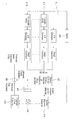
도 5는 본 발명에 따른 복조부의 일 실시예를 보인 상세 블록도로서, 위상 분리기(511), 수치 제어 발진기(Numerically Controlled Oscillator ; NCO)(512), 제1 곱셈기(513), 리샘플러(514), 제2 곱셈기(515), 정합 필터(Matched Filter)(516), DC 제거기(517), 데시메이터(518), 타이밍 복구부(520), 반송파 복구부(530), 및 위상 보상부(540)를 포함하여 구성된다. 5 is a detailed block diagram illustrating an embodiment of a demodulator according to the present invention, and includes a
상기 타이밍 복구부(520)는 버퍼(521), 데시메이터(522), 타이밍 에러 검출기(523), 루프 필터(524), 유지기(Holder)(525), 및 NCO(526)를 포함하여 구성된다. The
상기 반송파 복구부(530)는 버퍼(531), 주파수 옵셋 추정기(532), 루프 필터(533), 유지기(534), 가산기(535), 및 NCO(536)를 포함하여 구성된다.The
상기 위상 보상부(540)는 버퍼(541), 주파수 옵셋 추정기(542), 유지기(543), NCO(544), 및 곱셈기(545)를 포함하여 구성된다. The
상기 데시메이터(518,522)는 복조부(540)로 입력되는 신호가 ADC(430)에서 N배로 오버샘플링(oversampling)되었을 경우에 필요한 부분이다. 즉, N은 수신 신호의 샘플링 비율(sampling rate)을 나타낸다. 예를 들어, 입력 신호가 ADC(430)에서 2배로 오버 샘플링되었다면(N=2), 1 심볼에 2개의 샘플이 포함되어 있음을 의미하고, 이 경우 상기 데시메이터(518,522)는 1/2 데시메이터이다. 상기 데시메이터(518,522)는 수신 신호의 오버샘플링 여부에 따라 바이패스될 수도 있다. The
이와 같이 구성된 도 5에서, 위상 분리기(511)는 ADC(430)에서 출력되는 통과대역 디지털 신호를 위상이 서로 -90ㅀ가 되는 실수 성분과 허수 성분의 통과대역 디지털 신호 즉, 복소 신호로 분리하여 제1 곱셈기(513)로 출력한다. 여기서, 설명의 편의를 위해 상기 위상 분리기(511)에서 출력되는 실수 성분의 신호를 I 신호라 하고, 허수 성분의 신호를 Q 신호라 한다. In FIG. 5 configured as described above, the
상기 제1 곱셈기(513)는 NCO(512)로부터 출력되는 상수(Constant)에 비례하는 주파수를 가지는 복소 신호에 상기 위상 분리기(511)에서 출력되는 통과대역 디지털 복소 신호(I,Q)를 곱하여, 상기 통과대역 디지털 복소신호(I,Q)를 기저대역 디지털 복소신호로 천이한다. 상기 제1 곱셈기(513)의 기저대역 디지털 신호는 리샘플러(514)로 입력된다. The first multiplier 513 multiplies a complex signal having a frequency proportional to a constant output from the
상기 리샘플러(514)는 제1 곱셈기(513)에서 출력되는 신호를 타이밍 복구부(520)의 NCO(526)에서 제공하는 타이밍 클럭에 맞게 리샘플링하여 제2 곱셈기(515)로 출력한다.The
예를 들어, 상기 ADC(430)가 25MHz의 고정 발진자를 사용할 경우, 상기 ADC (430)와 위상 분리기(511), 제1 곱셈기(513)를 거쳐 생성된 25MHz 주파수를 갖는 기저대역 디지털 신호는 상기 리샘플러(514)에서 보간(interpolation) 과정을 거쳐 수신 신호의 심볼 클럭의 2배의 주파수 즉, 21.524476MHz 주파수를 갖는 기저대역 디지털 신호로 복원된다. 만일 상기 ADC(430)가 타이밍 복구부(520)의 NCO(526)의 출력 주파수를 샘플링 주파수로 이용하는 경우, 즉 가변 주파수를 이용하여 A/D 변환을 수행하는 경우에는 상기 리샘플러(514)는 필요없게 된다. For example, when the
상기 제2 곱셈기(515)는 상기 리샘플러(514)의 출력에 반송파 복구부(530)의 NCO(536)의 출력 주파수를 곱하여 상기 리샘플러(514)의 출력 신호에 포함된 잔류 반송파를 보상한 후 정합 필터(516)와 타이밍 복구부(520)로 출력한다. The
상기 정합 필터(516)에서 정합 필터링된 신호는 DC 제거기(517)와 기지 데이터 검출 및 초기 주파수 옵셋 추정부(450), 및 반송파 복구부(530)로 입력된다. The signal filtered by the matched
상기 기지 데이터 검출 및 초기 주파수 옵셋 추정부(450)는 주기적 또는 비주기적으로 전송되는 기지 데이터 열의 위치를 검출함과 동시에 상기 기지 데이터 검출 과정에서 초기 주파수 옵셋(initial frequency offset)을 추정한다. The known data detection and initial frequency offset
즉, VSB 데이터 프레임이 수신되는 동안 상기 기지 데이터 검출 및 초기 주파수 옵셋 추정부(450)는 VSB 데이터 프레임 안에 포함된 기지 데이터의 위치를 검출하고, 그 위치 정보(Known Sequence Position Indicator)를 복조부(440)의 타이밍 복구부(520), 반송파 복구부(530), 및 위상 보상부(540)로 출력한다. 또한 상기 기지 데이터 검출 및 초기 주파수 옵셋 추정부(450)는 초기 주파수 옵셋을 추정하여 반송파 복구부(530)로 출력한다.That is, while the VSB data frame is received, the known data detection and initial frequency offset
이때 상기 기지 데이터 검출 및 초기 주파수 옵셋 추정부(450)는 정합 필터(516)의 출력을 입력받을 수도 있고, 리샘플러(514)의 출력을 입력받을 수도 있으며, 이는 설계자의 선택 사항이다. In this case, the known data detection and initial frequency offset
도 6은 본 발명에 따른 기지 데이터 검출 및 발생부의 일 실시예를 보인 상세 블록도로서, 기지 데이터 위치 정보와 함께 초기 주파수 옵셋을 추정하는 예를 보이고 있다. 도 6은 입력되는 신호가 N배로 오버샘플링(oversampling)되었을 경우를 고려한 도면이다.FIG. 6 is a detailed block diagram illustrating an example of a known data detection and generation unit according to the present invention, and illustrates an example of estimating an initial frequency offset along with known data location information. FIG. 6 illustrates a case in which an input signal is oversampled by N times.
도 6을 보면, 기지 데이터 검출 및 발생부는 병렬로 구성된 N개의 부분 상관부(611~61N)와 기지 데이터 위치 검출 및 주파수 옵셋 결정부(620), 기지 데이터 추출부(630), 버퍼(640), 곱셈기(650), NCO(660), 주파수 옵셋 추정기(670), 및 가산기(680)를 포함하여 구성된다. 6, the known data detection and generation unit includes N
상기 첫 번째 부분 상관부(611)는 1/N 데시메이터, 및 부분 상관기로 구성된다.The first
상기 두 번째 부분 상관부(612)는 1 샘플 지연기, 1/N 데시메이터, 및 부분 상관기로 구성된다.The second
상기 N 번째 부분 상관부(61N)는 N-1 샘플 지연기, 1/N 데시메이터, 및 부분 상관기로 구성된다. The Nth
이는 오버샘플링된 심볼 내 각 샘플들의 위상을 원래 심볼의 위상과 일치시키고, 나머지 위상에 있는 샘플들을 데시메이션한 후 각각 부분 상관을 수행하기 위해서이다. 즉, 입력 신호는 각 샘플링 위상(sampling phase)별로 1/N의 비율로 데시메이션되어 각 부분 상관기(partial correlator)를 통과한다.This is to match the phase of each sample in the oversampled symbol to the phase of the original symbol, to decimate the samples in the remaining phases and then to perform partial correlation, respectively. That is, the input signal is decimated at a ratio of 1 / N for each sampling phase and passes through each partial correlator.
예를 들어, 입력 신호가 2배로 오버샘플링되었다면 즉, N=2라면 1 심볼에 2개의 샘플이 포함되어 있음을 의미하고, 이 경우 상기 부분 상관부는 2개가 필요하 며, 1/N 데시메이터는 1/2 데시메이터이다.For example, if the input signal is oversampled twice, that is, N = 2, it means that one symbol contains two samples, in which case the partial correlator needs two and the 1 /
이때 첫 번째 부분 상관부(611)의 1/N 데시메이터는 입력 샘플 중 심볼 위치와 심볼 위치 사이에 있는 샘플을 데시메이트(제거)하여 부분 상관기로 출력한다. At this time, the 1 / N decimator of the first
그리고 두 번째 부분 상관부(612)의 1샘플 지연기는 입력 샘플을 1샘플 지연시켜 1/N 데시메이터로 출력한다. 이어 상기 1/N 데시메이터는 상기 1 샘플 지연기에서 입력되는 샘플 중 심볼 위치와 심볼 위치 사이에 있는 샘플을 데시메이트(제거)하여 부분 상관기로 출력한다. The one-sample delay of the second
상기 각 부분 상관기는 VSB 심볼의 기 설정된 주기마다 상관값과 그 순간에서의 대략적인 주파수 옵셋 추정 값을 기지 데이터 위치 검출 및 주파수 옵셋 결정부(620)로 출력한다.Each of the partial correlators outputs a correlation value and an approximate frequency offset estimation value at the instant of each VSB symbol to the known data position detection and frequency offset
상기 기지 데이터 위치 검출 및 주파수 옵셋 결정부(620)는 각 샘플링 위상별 부분 상관기의 출력을 데이터 그룹 주기 또는 정해진 주기 동안 저장한 후 그 값들 가운데 상관값이 최대인 위치를 기지 데이터의 수신 위치로 판단하고 그 순간의 주파수 옵셋 추정 값을 수신 시스템의 대략적인 주파수 옵셋 값으로 최종 결정한다. The known data position detection and frequency offset
이때 상기 기지 데이터 위치 정보(Known Sequence Position Indicator)는 기지 데이터 추출부(630)로 입력되고, 추정된 대략적인 주파수 옵셋은 가산기(680)와 NCO(660)로 입력된다. In this case, the known sequence position indicator is input to the known
한편 버퍼(640)는 상기 N개의 부분 상관부(611~61N)에서 기지 데이터 위치 검출과 대략적 주파수 옵셋을 추정하는 동안, 수신 데이터를 임시 저장한 후 기지 데이터 추출부(630)로 출력한다. Meanwhile, the
상기 기지 데이터 추출부(630)는 상기 기지 데이터 위치 검출 및 주파수 옵셋 결정부(620)에서 출력되는 기지 데이터 위치 정보를 이용하여 상기 버퍼(640)의 출력으로부터 기지 데이터를 추출한 후 곱셈기(650)로 출력한다.The known
상기 NCO(660)는 상기 기지 데이터 위치 검출 및 주파수 옵셋 결정부(620)에서 출력되는 대략적인 주파수 옵셋에 해당하는 복소 신호를 생성하여 곱셈기(650)로 출력한다.The
상기 곱셈기(650)는 상기 기지 데이터 추출부(630)에서 출력되는 기지 데이터에 상기 NCO(660)의 복소 신호를 곱하여 대략적인 주파수 옵셋이 보상된 기지 데이터를 주파수 옵셋 추정기(670)로 출력한다.The
상기 주파수 옵셋 추정기(670)는 대략적인 주파수 옵셋이 보상된 기지 데이터로부터 미세 주파수 옵셋을 추정하여 가산기(680)로 출력한다.The frequency offset
상기 가산기(680)는 대략적인 주파수 옵셋과 미세 주파수 옵셋을 더하고 그 결과를 최종 초기 주파수 옵셋으로 하여 상기 복조부(440) 내 반송파 복구부(530)의 가산기(535)로 출력한다. 즉, 본 발명은 초기 동기 획득시에 대략적인 주파수 옵셋 뿐만 아니라 미세 주파수 옵셋을 추정하여 이용함으로써, 초기 주파수 옵셋의 추정 성능을 향상시킬 수 있다. The
만일 상기 기지 데이터가 도 2와 같이 데이터 그룹 내에 삽입되어 전송된다고 가정하면, 상기 기지 데이터 검출 및 초기 주파수 옵셋 추정부(450)는 상기 바디 영역이 시작되는 부분에 추가적으로 삽입된 기지 데이터를 이용하여 초기 주파 수 옵셋을 추정할 수 있다. If it is assumed that the known data is inserted into the data group and transmitted as shown in FIG. 2, the known data detection and initial frequency offset
그리고 상기 기지 데이터 검출 및 초기 주파수 옵셋 추정부(450)에서 추정한 상기 바디 영역 내에 주기적으로 삽입된 기지 데이터의 위치 정보는 타이밍 복구부(420)의 타이밍 에러 검출기(523)와 반송파 복구부(530)의 주파수 옵셋 추정기(532), 및 위상 보상부(540)의 주파수 옵셋 추정기(542)로 입력된다. In addition, the position information of the known data periodically inserted into the body region estimated by the known data detection and initial frequency offset
즉, 상기 제2 곱셈기(515)의 출력은 상기 타이밍 복구부(520) 내 버퍼(521)에서 일시 저장된 후 데시메이터(522)를 통해 타이밍 에러 검출기(Timing Error Detector)(523)로 입력된다. That is, the output of the
만일 상기 제2 곱셈기(515)의 출력이 N배로 오버샘플링(oversampling)되었다면, 상기 버퍼(521)의 출력은 데시메이터(522)에서 1/N로 데시메이트된 후 타이밍 에러 검출기(523)로 입력된다. 즉, 상기 데시메이터(522)는 VSB 심볼 주기로 입력 신호를 데시메이션한다. 또한 상기 버퍼(521)는 제2 곱셈기(515)의 출력 대신 정합 필터(516)의 출력을 입력받을 수도 있다. If the output of the
상기 타이밍 에러 검출기(523)는 상기 기지 데이터 위치 정보를 이용하여 기지 데이터 열이 입력될 때 상기 정합 필터링 전 또는 후의 기지 데이터 열로부터 타이밍 에러를 검출하여 루프 필터(524)로 출력한다. 따라서 검출된 타이밍 에러 정보는 기지 데이터 열의 반복 주기마다 한 번씩 구해진다. The
즉, 상기 타이밍 에러 검출기(523)는 일 실시예로서, 만일 도 3과 같이 동일한 패턴을 갖는 기지 데이터 열이 주기적으로 삽입되어 전송된다면 상기 기지 데이터를 이용하여 타이밍 에러를 검출할 수 있다.That is, as an example, the
상기 기지 데이터를 이용하여 타이밍 에러를 검출하는 방법은 여러 가지가 있을 수 있다. 본 발명에서는 일 실시예로 시간 영역에서 송/수신측의 약속에 의해 알고 있는 기지 데이터와 수신 데이터와의 상관 특성을 이용하여 타이밍 에러를 검출하거나, 주파수 영역에서 수신되는 두 기지 데이터의 상관 특성을 이용하여 타이밍 에러를 검출한다. 또 다른 실시예로, 수신 신호의 스펙트럼의 측대역을 이용하여 타이밍 에러를 검출하는 스펙트럴 라인 방법을 적용하여 타이밍 에러를 검출할 수도 있다. There are various methods for detecting the timing error using the known data. According to an embodiment of the present invention, a timing error is detected by using a correlation characteristic between known data and received data known by a promise of a transmitting / receiving party in a time domain, or a correlation characteristic between two known data received in a frequency domain is detected. To detect timing errors. In another embodiment, a spectral line method of detecting a timing error using a sideband of the spectrum of a received signal may be applied to detect a timing error.
상기 루프 필터(524)는 상기 타이밍 에러 검출기(523)에서 검출된 타이밍 에러를 필터링하여 유지기(525)로 출력한다. The
상기 유지기(525)는 상기 루프 필터(524)에서 필터링되어 출력되는 타이밍 에러를 기지 데이터 열의 주기동안 유지시킨 후 NCO(526)로 출력한다. The
상기 NCO(526)는 상기 유지기(525)에서 출력되는 타이밍 에러를 누적하고, 누적된 타이밍 에러의 위상 성분을 리샘플러(514)로 출력하여 리샘플러(514)의 샘플링 타이밍을 조절한다. 즉, 상기 리샘플러(514)에서 올바른 위상의 신호가 보간되어 출력되도록 한다. 여기서 상기 루프 필터(524)와 유지기(525)의 위치는 서로 바뀔 수 있다. The
한편 상기 반송파 복구부(530)의 버퍼(531)도 상기 정합 필터(416)의 입력 또는 출력 데이터를 입력받아 일시 저장한 후 주파수 옵셋 추정기(532)로 출력한다. 상기 주파수 옵셋 추정기(532)는 상기 기지 데이터 검출 및 초기 주파수 옵셋 추정부(450)에서 출력되는 기지 데이터 위치 정보를 이용하여 기지 데이터 열이 입 력될 때 상기 정합 필터링 전 또는 후의 기지 데이터 열로부터 주파수 옵셋을 추정하여 루프 필터(533)로 출력한다. 따라서 추정된 주파수 옵셋값은 기지 데이터 열의 반복 주기마다 한 번씩 구해진다. Meanwhile, the
상기 루프 필터(533)는 주파수 옵셋 추정기(532)에서 추정된 주파수 옵셋값을 저역 통과 필터링하여 유지기(534)로 출력한다. 상기 유지기(534)는 저역 통과 필터링된 주파수 옵셋 추정값을 기지 데이터 열의 주기 동안 유지시킨 후 가산기(535)로 출력한다. 여기서 상기 루프 필터(533)와 유지기(534)의 위치는 서로 바뀌어도 가능하다. 상기 가산기(535)는 상기 기지 데이터 검출 및 초기 주파수 옵셋 추정부(450)에서 추정된 초기 주파수 옵셋값과 상기 유지기(534)에서 출력되는 주파수 옵셋값을 더하여 NCO(536)로 출력한다. 상기 NCO(536)는 가산기(535)의 출력 주파수 옵셋에 해당하는 복소 신호를 생성하여 제2 곱셈기(515)로 출력한다. The
상기 제2 곱셈기(515)는 리샘플러(514)의 출력에 반송파 복구부(530)의 NCO(536)의 출력을 곱하여 상기 리샘플러(514)의 출력 신호에 포함된 반송파 옵셋을 제거한다. The
한편 상기 DC 제거기(517)는 정합 필터링된 신호로부터 VSB 신호의 송신 과정에서 삽입된 파일럿 톤을 제거한 후 위상 보상부(540)로 출력한다. The
도 7은 본 발명에 따른 DC 제거기의 일 실시예를 보인 상세 블록도로서, 복소 입력 신호의 실수 성분(In-phase, I)과 허수 성분(Quadrature, Q)에 대해 동일한 신호 처리 과정을 거쳐 각 성분에서의 DC 값을 추정한 후 제거한다. FIG. 7 is a detailed block diagram illustrating an embodiment of a DC remover according to the present invention. Each of the real components (In-phase, I) and imaginary components (Quadrature, Q) of a complex input signal is subjected to the same signal processing. The DC value in the component is estimated and then removed.
이를 위해 도 7은 크게 제1,제2 DC 추정 및 제거기(710,720)로 구성된다. To this end, FIG. 7 is largely comprised of first and second DC estimators and
상기 제1 DC 추정 및 제거기(710)는 L 샘플 버퍼(711), DC 추정기(712), M 샘플 유지기(713), C 샘플 지연기(714), 및 감산기(715)를 포함하여 구성되며, 실수 성분의 DC를 추정하여 제거한다. The first DC estimator and
상기 제1 DC 추정 및 제거기(710)는 L 샘플 버퍼(711), DC 추정기(712), M 샘플 유지기(713), C 샘플 지연기(714), 및 감산기(715)를 포함하여 구성되며, 허수 성분의 DC를 추정하여 제거한다. The first DC estimator and
본 발명에서는 제1,제2 DC 추정 및 제거기(710,720)의 입력 신호만 다를 뿐 두 구조가 동일하므로 제1 DC 추정 및 제거기(710)에 대해서 상세히 설명하고, 제2 DC 추정 및 제거기(720)의 상세 설명은 생략한다. In the present invention, since only the input signals of the first and second DC estimators and
즉, 정합 필터(516)에서 정합 필터링된 실수 성분의 신호는 DC 제거기(517) 내 제1 DC 추정 및 제거기(710)의 L 샘플 버퍼(711)로 입력되어 저장된다. 상기 L 샘플 버퍼(711)는 L 샘플 길이를 갖는 버퍼이며, 상기 L 샘플 버퍼(711)의 출력은 DC 추정기(712)와 C 샘플 지연기(714)로 입력된다.That is, the signal of the real component matched and filtered by the matched
상기 DC 추정기(712)는 상기 버퍼(711)에서 출력되는 L 샘플 길이의 데이터를 이용하여 하기의 수학식 1과 같이 DC 값을 추정한다. The
![]()
![]()
상기 수학식 1에서 x[n]은 버퍼(711)에 저장된 입력 샘플 데이터를 나타내고, y[n]은 DC 추정값을 나타낸다.In
즉, 상기 DC 추정기(712)는 버퍼(711)에 저장된 L개 샘플 데이터를 누적한 후 L로 나눈 값으로 DC 값을 추정하는데 이때, 버퍼(711)에 저장된 입력 샘플 데이터를 M 샘플만큼 이동(shift)시켜 M 샘플마다 한 번씩 DC 추정값을 내보낸다. That is, the
도 8은 DC 추정에 사용되는 입력 샘플 데이터의 이동을 나타낸다. 예를 들어, M=1일 경우 DC 추정기(712)는 버퍼(711)에 매 샘플이 이동할 때마다 DC 값을 추정하여 매 샘플마다 그 결과를 내보낸다. 만일 M=L일 경우 DC 추정기(712)는 버퍼(711)에 L 샘플이 이동할 때마다 DC 값을 추정하여 L 샘플마다 출력을 내보내므로, 이 경우 DC 추정기(712)는 L 샘플의 블록 단위로 동작하는 DC 추정기가 된다. 여기서 상기 M 값은 1과 L 사이의 어떤 값도 가능하다. 8 shows the movement of input sample data used for DC estimation. For example, when M = 1, the
이와 같이 상기 DC 추정기(712)의 출력은 M 샘플마다 나오므로, M 샘플 유지기(713)는 DC 추정기(712)에서 추정된 DC 값을 M 샘플 동안 유지시켜 감산기(715)로 출력한다. 그리고 C 샘플 지연기(714)는 버퍼(711)에 저장된 입력 샘플 데이터를 C 샘플만큼 지연시킨 후 감산기(715)로 출력한다. 상기 감산기(715)는 C 샘플 지연기(714)의 출력에서 M 샘플 유지기(713)의 출력을 빼, 실수 성분의 DC가 제거된 신호를 출력한다.As described above, since the output of the
여기서, 상기 C 샘플 지연기(714)는 상기 DC 추정기(712)의 출력을 어느 부분의 입력 샘플 데이터에 보상해 줄지를 결정한다. 구체적으로, DC 추정 및 제거기(710)는 DC를 추정하는 DC 추정기(712)와 추정된 DC 값을 입력 샘플 데이터에 보상해주는 감산기(715)로 나누어 볼 수 있다. 이때 상기 C 샘플 지연기(714)는 추정된 DC 값을 입력 샘플 데이터의 어느 부분에 보상할 지를 결정한다. 예를 들어, C = 0이면 L 샘플을 이용해 DC 추정한 값을 L 샘플의 처음 부분에 보상해 주게 되고, C = L이면 L 샘플을 이용해 DC 추정한 값을 L 샘플의 끝 부분에 보상하게 된다. Here, the
상기와 같은 방법으로 상기 DC 제거기(517)에서 DC가 제거된 데이터는 위상 보상기(540)의 버퍼(541)와 주파수 옵셋 추정기(542)로 입력된다. In the same manner as described above, data from which DC is removed by the
상기 주파수 옵셋 추정기(542)는 상기 기지 데이터 검출 및 초기 주파수 옵셋 추정부(450)에서 출력되는 기지 데이터 위치 정보를 이용하여 기지 데이터 열이 입력될 때 상기 DC 제거기(517)에서 DC가 제거되어 입력되는 기지 데이터 열로부터 주파수 옵셋을 추정하여 유지기(543)로 출력한다. 마찬가지로 상기 주파수 옵셋 추정값은 기지 데이터 열의 반복 주기마다 한 번씩 구해진다. The frequency offset
따라서 상기 유지기(543)는 상기 주파수 옵셋 추정값을 기지 데이터 열의 주기 동안 유지시킨 후 NCO(544)로 출력한다. 상기 NCO(544)는 유지기(543)에서 유지된 주파수 옵셋에 해당하는 복소 신호를 생성하여 곱셈기(545)로 출력한다. Thus, the
상기 곱셈기(545)는 상기 버퍼(541)에서 일정 시간 지연된 데이터에 상기 NCO(544)에서 출력되는 복소 신호를 곱하여 상기 지연 데이터에 포함된 위상 변화를 보상한다. 상기 곱셈기(545)에서 위상 변화가 보상된 데이터는 데시메이터(518)를 거쳐 등화부(460)로 입력된다. 이때 상기 위상 보상부(540)의 주파수 옵셋 추정기에서 추정된 주파수 옵셋은 루프 필터를 거치지 않음으로 기지 데이터 열 사이의 위상 차이 즉, 위상 옵셋을 나타낸다. The
본 발명은 상술한 실시예에 한정되지 않으며, 첨부된 청구범위에서 알 수 있는 바와 같이 본 발명이 속한 분야의 통상의 지식을 가지 자에 의해 변형이 가능하 고 이러한 변형은 본 발명의 범위에 속한다. The present invention is not limited to the above-described embodiments, and can be modified by those skilled in the art as can be seen from the appended claims, and such modifications are within the scope of the present invention. .
이상에서 설명한 바와 같은 본 발명에 따른 디지털 방송 시스템 및 처리 방법은 채널을 통하여 부가 데이터를 송신할 때 오류에 강하고 또한 기존의 VSB 수신기와도 호환성이 가능한 이점이 있다. 더불어 기존의 VSB 시스템보다 고스트와 잡음이 심한 채널에서도 부가 데이터를 오류없이 수신할 수 있는 이점이 있다. As described above, the digital broadcasting system and the processing method according to the present invention have the advantage of being resistant to errors and compatible with existing VSB receivers when transmitting additional data through a channel. In addition, there is an advantage that the additional data can be received without error even in a ghost and noisy channel than the conventional VSB system.
또한 본 발명은 송신측에서는 송/수신측의 약속에 의해 정해진 패턴을 갖는 기지 데이터를 주기적 또는 비주기적으로 송신하고, 수신측에서는 상기 기지 데이터를 이용하여 반송파 복구, 타이밍 복구뿐만 아니라, 반복되는 기지 데이터 사이의 위상 변화 보상에도 이용함으로써, 채널 변화가 심하거나 노이즈에 약한 환경에서 수신 성능을 향상시킬 수 있다.In addition, the present invention periodically or aperiodically transmits known data having a pattern determined by an appointment of a transmitting / receiving side, and a receiving side uses the known data not only for carrier recovery and timing recovery, but also for repeated known data. It is also possible to improve the reception performance in an environment where the channel change is severe or the noise is vulnerable by using it for phase change compensation of.
이러한 본 발명은 채널 변화가 심하고 노이즈에 대한 강건성이 요구되는 휴대용 및 이동수신기에 적용하면 더욱 효과적이다. The present invention is more effective when applied to portable and mobile receivers that require severe channel changes and robustness against noise.
이상 설명한 내용을 통해 당업자라면 본 발명의 기술 사상을 일탈하지 아니하는 범위에서 다양한 변경 및 수정이 가능함을 알 수 있을 것이다.It will be apparent to those skilled in the art that various modifications and variations can be made in the present invention without departing from the spirit or scope of the invention.
따라서 본 발명의 기술적 범위는 실시예에 기재된 내용으로 한정되는 것이 아니라 특허 청구의 범위에 의하여 정해져야 한다. Therefore, the technical scope of the present invention should not be limited to the contents described in the embodiments, but should be defined by the claims.
Claims (31)
Priority Applications (8)
| Application Number | Priority Date | Filing Date | Title |
|---|---|---|---|
| KR1020060063877A KR101276804B1 (en) | 2006-07-07 | 2006-07-07 | Digital broadcasting system and processing method |
| PCT/KR2007/000160 WO2008004737A1 (en) | 2006-07-07 | 2007-01-09 | Digital broadcasting system and method of processing data |
| MX2009000040A MX2009000040A (en) | 2006-07-07 | 2007-01-09 | Digital broadcasting system and method of processing data. |
| CA2656976A CA2656976C (en) | 2006-07-07 | 2007-01-09 | Digital broadcasting system and method of processing data |
| US11/774,520 US7813445B2 (en) | 2006-07-07 | 2007-07-06 | DTV transmitter and method of processing digital broadcast data therein |
| US12/831,848 US8081713B2 (en) | 2006-07-07 | 2010-07-07 | DTV receiving system and method of processing DTV signal |
| US13/282,374 US8325849B2 (en) | 2006-07-07 | 2011-10-26 | Transmitting system and method of processing broadcast data in the transmitting system |
| US14/341,552 USRE46883E1 (en) | 2006-07-07 | 2014-07-25 | Transmitting system and method of processing broadcast data in the transmitting system |
Applications Claiming Priority (1)
| Application Number | Priority Date | Filing Date | Title |
|---|---|---|---|
| KR1020060063877A KR101276804B1 (en) | 2006-07-07 | 2006-07-07 | Digital broadcasting system and processing method |
Publications (2)
| Publication Number | Publication Date |
|---|---|
| KR20080004935A KR20080004935A (en) | 2008-01-10 |
| KR101276804B1 true KR101276804B1 (en) | 2013-06-18 |
Family
ID=39215510
Family Applications (1)
| Application Number | Title | Priority Date | Filing Date |
|---|---|---|---|
| KR1020060063877A Expired - Fee Related KR101276804B1 (en) | 2006-07-07 | 2006-07-07 | Digital broadcasting system and processing method |
Country Status (1)
| Country | Link |
|---|---|
| KR (1) | KR101276804B1 (en) |
Families Citing this family (1)
| Publication number | Priority date | Publication date | Assignee | Title |
|---|---|---|---|---|
| CN114050845B (en) * | 2021-11-25 | 2023-03-14 | 思澈科技(上海)有限公司 | Coherent demodulation method of Bluetooth EDR receiver |
Citations (2)
| Publication number | Priority date | Publication date | Assignee | Title |
|---|---|---|---|---|
| US5757416A (en) | 1993-12-03 | 1998-05-26 | Scientific-Atlanta, Inc. | System and method for transmitting a plurality of digital services including imaging services |
| EP1555826A1 (en) | 2004-01-17 | 2005-07-20 | Samsung Electronics Co., Ltd. | Apparatus and method for inserting and extracting value added data in a transport stream-based MPEG-2 system |
-
2006
- 2006-07-07 KR KR1020060063877A patent/KR101276804B1/en not_active Expired - Fee Related
Patent Citations (2)
| Publication number | Priority date | Publication date | Assignee | Title |
|---|---|---|---|---|
| US5757416A (en) | 1993-12-03 | 1998-05-26 | Scientific-Atlanta, Inc. | System and method for transmitting a plurality of digital services including imaging services |
| EP1555826A1 (en) | 2004-01-17 | 2005-07-20 | Samsung Electronics Co., Ltd. | Apparatus and method for inserting and extracting value added data in a transport stream-based MPEG-2 system |
Also Published As
| Publication number | Publication date |
|---|---|
| KR20080004935A (en) | 2008-01-10 |
Similar Documents
| Publication | Publication Date | Title |
|---|---|---|
| KR101253185B1 (en) | Digital broadcasting system and data processing method | |
| KR101285887B1 (en) | Digital broadcasting system and method of processing data in digital broadcasting system | |
| KR100462630B1 (en) | Repetitive-PN1023-sequence echo-cancellation reference signal for single-carrier digital television broadcast systems | |
| KR101276851B1 (en) | Apparatus and Method for transmitting Digital broadcasting signal | |
| KR101227504B1 (en) | Digital broadcasting system and processing method | |
| KR101285888B1 (en) | Digital broadcasting system and method of processing data in digital broadcasting system | |
| KR101199387B1 (en) | Digital broadcasting system and data processing method | |
| KR101199374B1 (en) | Digital broadcasting system and processing method | |
| KR101276804B1 (en) | Digital broadcasting system and processing method | |
| KR101147769B1 (en) | Digital broadcasting system and processing method | |
| KR100584475B1 (en) | Digital TV Timing Offset Compensation Algorithm | |
| KR101208512B1 (en) | Digital broadcasting receive system and method | |
| KR100917214B1 (en) | Receiving system and data processing method | |
| KR101181778B1 (en) | Channel equarlizing method and apparatus, and digital broadcasting receive system | |
| KR101208514B1 (en) | Digital broadcasting receiver and processing method | |
| KR100921471B1 (en) | Digital broadcasting system and data processing method | |
| KR101208518B1 (en) | Digital broadcasting receiver and processing method |
Legal Events
| Date | Code | Title | Description |
|---|---|---|---|
| PA0109 | Patent application |
St.27 status event code: A-0-1-A10-A12-nap-PA0109 |
|
| PG1501 | Laying open of application |
St.27 status event code: A-1-1-Q10-Q12-nap-PG1501 |
|
| PN2301 | Change of applicant |
St.27 status event code: A-3-3-R10-R13-asn-PN2301 St.27 status event code: A-3-3-R10-R11-asn-PN2301 |
|
| R18-X000 | Changes to party contact information recorded |
St.27 status event code: A-3-3-R10-R18-oth-X000 |
|
| R18-X000 | Changes to party contact information recorded |
St.27 status event code: A-3-3-R10-R18-oth-X000 |
|
| A201 | Request for examination | ||
| E13-X000 | Pre-grant limitation requested |
St.27 status event code: A-2-3-E10-E13-lim-X000 |
|
| P11-X000 | Amendment of application requested |
St.27 status event code: A-2-2-P10-P11-nap-X000 |
|
| P13-X000 | Application amended |
St.27 status event code: A-2-2-P10-P13-nap-X000 |
|
| PA0201 | Request for examination |
St.27 status event code: A-1-2-D10-D11-exm-PA0201 |
|
| PE0902 | Notice of grounds for rejection |
St.27 status event code: A-1-2-D10-D21-exm-PE0902 |
|
| E13-X000 | Pre-grant limitation requested |
St.27 status event code: A-2-3-E10-E13-lim-X000 |
|
| P11-X000 | Amendment of application requested |
St.27 status event code: A-2-2-P10-P11-nap-X000 |
|
| P13-X000 | Application amended |
St.27 status event code: A-2-2-P10-P13-nap-X000 |
|
| E701 | Decision to grant or registration of patent right | ||
| PE0701 | Decision of registration |
St.27 status event code: A-1-2-D10-D22-exm-PE0701 |
|
| GRNT | Written decision to grant | ||
| PR0701 | Registration of establishment |
St.27 status event code: A-2-4-F10-F11-exm-PR0701 |
|
| PR1002 | Payment of registration fee |
St.27 status event code: A-2-2-U10-U11-oth-PR1002 Fee payment year number: 1 |
|
| PG1601 | Publication of registration |
St.27 status event code: A-4-4-Q10-Q13-nap-PG1601 |
|
| PN2301 | Change of applicant |
St.27 status event code: A-5-5-R10-R13-asn-PN2301 St.27 status event code: A-5-5-R10-R11-asn-PN2301 |
|
| P22-X000 | Classification modified |
St.27 status event code: A-4-4-P10-P22-nap-X000 |
|
| FPAY | Annual fee payment |
Payment date: 20160524 Year of fee payment: 4 |
|
| PR1001 | Payment of annual fee |
St.27 status event code: A-4-4-U10-U11-oth-PR1001 Fee payment year number: 4 |
|
| FPAY | Annual fee payment |
Payment date: 20170512 Year of fee payment: 5 |
|
| PR1001 | Payment of annual fee |
St.27 status event code: A-4-4-U10-U11-oth-PR1001 Fee payment year number: 5 |
|
| P22-X000 | Classification modified |
St.27 status event code: A-4-4-P10-P22-nap-X000 |
|
| FPAY | Annual fee payment |
Payment date: 20180514 Year of fee payment: 6 |
|
| PR1001 | Payment of annual fee |
St.27 status event code: A-4-4-U10-U11-oth-PR1001 Fee payment year number: 6 |
|
| FPAY | Annual fee payment |
Payment date: 20190514 Year of fee payment: 7 |
|
| PR1001 | Payment of annual fee |
St.27 status event code: A-4-4-U10-U11-oth-PR1001 Fee payment year number: 7 |
|
| PR1001 | Payment of annual fee |
St.27 status event code: A-4-4-U10-U11-oth-PR1001 Fee payment year number: 8 |
|
| PN2301 | Change of applicant |
St.27 status event code: A-5-5-R10-R13-asn-PN2301 St.27 status event code: A-5-5-R10-R11-asn-PN2301 |
|
| PR1001 | Payment of annual fee |
St.27 status event code: A-4-4-U10-U11-oth-PR1001 Fee payment year number: 9 |
|
| PR1001 | Payment of annual fee |
St.27 status event code: A-4-4-U10-U11-oth-PR1001 Fee payment year number: 10 |
|
| PC1903 | Unpaid annual fee |
St.27 status event code: A-4-4-U10-U13-oth-PC1903 Not in force date: 20230611 Payment event data comment text: Termination Category : DEFAULT_OF_REGISTRATION_FEE |
|
| PC1903 | Unpaid annual fee |
St.27 status event code: N-4-6-H10-H13-oth-PC1903 Ip right cessation event data comment text: Termination Category : DEFAULT_OF_REGISTRATION_FEE Not in force date: 20230611 |