KR101265893B1 - Controlling the angular extent of autostereoscopic viewing zones - Google Patents
Controlling the angular extent of autostereoscopic viewing zones Download PDFInfo
- Publication number
- KR101265893B1 KR101265893B1 KR1020077030637A KR20077030637A KR101265893B1 KR 101265893 B1 KR101265893 B1 KR 101265893B1 KR 1020077030637 A KR1020077030637 A KR 1020077030637A KR 20077030637 A KR20077030637 A KR 20077030637A KR 101265893 B1 KR101265893 B1 KR 101265893B1
- Authority
- KR
- South Korea
- Prior art keywords
- views
- display
- viewing
- autostereoscopic
- column
- Prior art date
- Legal status (The legal status is an assumption and is not a legal conclusion. Google has not performed a legal analysis and makes no representation as to the accuracy of the status listed.)
- Expired - Fee Related
Links
Images


Classifications
-
- H—ELECTRICITY
- H04—ELECTRIC COMMUNICATION TECHNIQUE
- H04N—PICTORIAL COMMUNICATION, e.g. TELEVISION
- H04N13/00—Stereoscopic video systems; Multi-view video systems; Details thereof
- H04N13/30—Image reproducers
- H04N13/302—Image reproducers for viewing without the aid of special glasses, i.e. using autostereoscopic displays
- H04N13/305—Image reproducers for viewing without the aid of special glasses, i.e. using autostereoscopic displays using lenticular lenses, e.g. arrangements of cylindrical lenses
-
- G—PHYSICS
- G02—OPTICS
- G02B—OPTICAL ELEMENTS, SYSTEMS OR APPARATUS
- G02B30/00—Optical systems or apparatus for producing three-dimensional [3D] effects, e.g. stereoscopic images
- G02B30/20—Optical systems or apparatus for producing three-dimensional [3D] effects, e.g. stereoscopic images by providing first and second parallax images to an observer's left and right eyes
- G02B30/26—Optical systems or apparatus for producing three-dimensional [3D] effects, e.g. stereoscopic images by providing first and second parallax images to an observer's left and right eyes of the autostereoscopic type
- G02B30/27—Optical systems or apparatus for producing three-dimensional [3D] effects, e.g. stereoscopic images by providing first and second parallax images to an observer's left and right eyes of the autostereoscopic type involving lenticular arrays
-
- G—PHYSICS
- G02—OPTICS
- G02B—OPTICAL ELEMENTS, SYSTEMS OR APPARATUS
- G02B30/00—Optical systems or apparatus for producing three-dimensional [3D] effects, e.g. stereoscopic images
- G02B30/20—Optical systems or apparatus for producing three-dimensional [3D] effects, e.g. stereoscopic images by providing first and second parallax images to an observer's left and right eyes
- G02B30/26—Optical systems or apparatus for producing three-dimensional [3D] effects, e.g. stereoscopic images by providing first and second parallax images to an observer's left and right eyes of the autostereoscopic type
- G02B30/27—Optical systems or apparatus for producing three-dimensional [3D] effects, e.g. stereoscopic images by providing first and second parallax images to an observer's left and right eyes of the autostereoscopic type involving lenticular arrays
- G02B30/29—Optical systems or apparatus for producing three-dimensional [3D] effects, e.g. stereoscopic images by providing first and second parallax images to an observer's left and right eyes of the autostereoscopic type involving lenticular arrays characterised by the geometry of the lenticular array, e.g. slanted arrays, irregular arrays or arrays of varying shape or size
Landscapes
- Physics & Mathematics (AREA)
- General Physics & Mathematics (AREA)
- Optics & Photonics (AREA)
- Engineering & Computer Science (AREA)
- Multimedia (AREA)
- Signal Processing (AREA)
- Geometry (AREA)
- Testing, Inspecting, Measuring Of Stereoscopic Televisions And Televisions (AREA)
- Stereoscopic And Panoramic Photography (AREA)
Abstract
디스플레이로부터 수신되는 오토스테레오스코픽 조망 구역의 증가된 각도 범위를 제공하는 방법 및 시스템이 개시되어 있다. 본 설계는 서로 관련되어 있는 기준선 갯수의 뷰들을 갖는 제1 데이터 컬럼을 제공하는 것을 포함하며, 상기 제1 데이터 컬럼은 디스플레이와 관련되어 있는 렌즈 시트에서의 하나 이상의 렌티큘에 제공된다. 본 설게는 제1 양의 데이터 컬럼을 하나 이상의 렌티큘에 제공되는 제2 양의 데이터 컬럼으로 변경하는 것을 더 포함한다. 제2 양의 데이터 컬럼은 기준선 갯수의 뷰들보다 더 많은 뷰들을 포함한다. 오토스테레오스코픽 이미지를 구성할 때 제2 양의 데이터 컬럼을 채용하는 것은 특정한 조망 거리에 대하여 오토스테레오스코픽 이미지의 비교적 선명한 조망을 갖는 디스플레이를 제공한다.
A method and system are disclosed for providing an increased angular range of autostereoscopic viewing zones received from a display. The design includes providing a first data column having a baseline number of views associated with each other, the first data column being provided to one or more lenticules in the lens sheet associated with the display. The design further includes changing the first amount of data column to a second amount of data column provided in the one or more lenticules. The second amount of data column includes more views than the baseline number of views. Employing a second amount of data columns when constructing an autostereoscopic image provides a display with a relatively clear view of the autostereoscopic image over a particular viewing distance.
Description
본 출원은 발명의 명칭이 "Controlling the Angular Extent of Autostereoscopic Viewing Zones"이고 발명자가 Lenny Lipton 등이며 2005년 6월 7일자로 출원된 미국 특허 가출원 일련 번호 제60/688,100호를 우선권으로 주장하며, 그 전체를 참조로서 포함한다. This application claims the priority of US Patent Provisional Serial No. 60 / 688,100, filed June 7, 2005, entitled "Controlling the Angular Extent of Autostereoscopic Viewing Zones" and inventor Lenny Lipton et al. The entirety is incorporated by reference.
본 설계는 오토스테레오스코픽 이미지의 투사에 관한 것이며, 보다 자세하게는, 디스플레이로부터의 광범위한 조망 거리 상에서 오토스테레오스코픽 디스플레이로부터 수신되는 오토스테레오스코픽 이미지에 대한 강한 깊이 효과(strong depth effect)를 발생시키는 것에 관한 것이다. This design relates to the projection of an autostereoscopic image, and more particularly, to generating a strong depth effect on an autostereoscopic image received from an autostereoscopic display over a wide viewing distance from the display. will be.
오토스테레오스코픽 디스플레이는 관찰자에 의해 착용되는 개별적인 선택 장치(안경)를 이용하지 않고 스테레오스코픽 이미지의 조망을 가능하게 하도록, 선택 장치로서 렌티큘러 시트(및 일부 경우에, 렌티큘러 시트와 다소 광학적으로 호환성이 있는 래스터 배리어(raster barrier))를 이용한다. 이들 유형의 디스플레이에 대하여 이용되는 기술 용어는, 2보다 많은 뷰들이 제공되는 경우, "파노라마그램(panoramagram)" 또는 때때로 "패럴랙스 파노라마그램(parallax panoramagram)" 이다. The autostereoscopic display is somewhat optically compatible with the lenticular sheet (and in some cases, the lenticular sheet) as an optional device to enable viewing of stereoscopic images without the use of individual selection devices (glasses) worn by the observer. Raster barriers are used. The technical term used for these types of displays is "panoramagram" or sometimes "parallax panoramagram" when more than two views are provided.
Okoshi의 3차원 이미징 기술[Three Dimensional Imaging Techniques(NY Academic Press, 1976)]에 의해 설명된 바와 같이, 파노라마그램에서는 복수의 투시 뷰들이 합성되어 렌즈 시트에 의해 이미징된다. 렌티큘러(또는 래스터 배리어) 스테레오스코픽 디스플레이에서, 하나의 관심 대상은 디스플레이에 대한 머리 움직임 또는 사용자 위치이다. 수평 방향에서의 머리 움직임은 관찰자가 조망 구역 내에서 투시의 변화를 볼 수 있게 하는데, 조망 구역은 디스플레이에 대한 공간 영역이며, 여기서 디스플레이 상의 이미지들이 조망된다. 관찰자가 조망 구역들 간을 이동하는 것과 같이 구역에서 구역으로 트랜지션할 때 투시 뷰들이 인접 조망 구역에서 반복한다. 즉, 1차 조망 구역에서 발생한 변화하는 투시들은 관찰자가 측방향으로 이동할 때 2차 구역 및 다른 주변 구역에서 반복한다. 이들 2차, 3차, 및 n차 조망 구역은 1차 구역과 유사한 이미지 품질을 갖는다. n차 구역을 넘으면, 상대적인 이미지 품질이 상당히 열화되기 쉽다. 성능은 1차 구역에 대하여 대칭적이며, 구역들의 각도 범위는 비슷하다. 구역에서 구역으로의 트랜지션은 전체의 모든 구역들이 조망가능 이미지의 최대 각도 범위를 제공하는 점에서 통상적으로 간단하다. As it described by Okoshi 3-D imaging technology [Three Dimensional Imaging Techniques (Academic Press NY, 1976)], a plurality of perspective views the panorama grams have been combined to be imaged by the lens sheet. In a lenticular (or raster barrier) stereoscopic display, one object of interest is head movement or user position relative to the display. Head movement in the horizontal direction allows the observer to see a change in perspective within the viewing zone, which is the spatial region for the display where the images on the display are viewed. Perspective views repeat in adjacent viewing zones as the observer transitions from zone to zone, such as moving between viewing zones. That is, changing perspectives occurring in the primary viewing zone repeat in the secondary zone and other surrounding zones as the observer moves laterally. These secondary, tertiary and n-th order viewing zones have similar image quality as the primary zone. Beyond the nth order zone, relative image quality is likely to degrade significantly. The performance is symmetrical with respect to the primary zone and the angle range of the zones is similar. The transition from zone to zone is usually simple in that all zones throughout provide the maximum angular range of the viewable image.
스크린의 평면에서 선택이 발생할 때, 많은 투시 뷰들은 넓은 각도 범위를 갖는 조망 구역을 제공하는 것이 요구된다. 때때로 패럴랙스 스테레오그램이라 불리는 단지 2개의 뷰만이 제공되는 디스플레이의 경우, 약간의 머리 움직임이 허용가능하고 관찰자의 위치가 제약받는다. 이러한 움직임의 제약은 불편하고 바람직하 지 않다. When selection occurs in the plane of the screen, many perspective views are required to provide a viewing area with a wide angular range. For displays where only two views, sometimes called parallax stereograms, are provided, some head movement is acceptable and the viewer's position is constrained. This limitation of movement is inconvenient and undesirable.
전자 디스플레이 파노라마그램은 2개의 다른 조망 상황에서 양호하게 기능하도록 조정될 수 있다. 첫째는 예를 들어 디스플레이로부터 4 내지 15 피트 떨어져 있는 상보(walk-up) 조망 거리의 범위이고, 또한 예를 들어, 디스플레이가 높이 탑재되어 15 피트 이상에서 조망되는 공항 환경에 일치하는 거리로부터의 상보 조망 거리의 범위이다. 현재, 상업적으로 이용가능한 어떤 파노라마그램도 시나리오 양쪽 모두에서 양호하게 실행하지 못한다. The electronic display panoramagram can be adjusted to function well in two different viewing situations. The first is a range of walk-up viewing distances, for example, 4 to 15 feet away from the display, and also, for example, from distances consistent with the airport environment where the display is mounted high and viewed from 15 feet or more. It is the range of view distance. Currently, no commercially available panoramagrams perform well in both scenarios.
따라서, 이전에 이용가능한 설계들은 디스플레이에 대한 뷰어 위치에서의 변동과 문제를 겪는다. 뷰어가 디스플레이로부터 여러 거리에 위치되는 것을 가능하게 함으로써 이미지의 오토스테레오스코픽 디스플레이를 강화시키거나 최적화하는 설계를 제공하는 것이 바람직하다. Thus, previously available designs suffer from variations and problems in viewer position relative to the display. It is desirable to provide a design that enhances or optimizes the autostereoscopic display of an image by allowing the viewer to be positioned at various distances from the display.
본 설계의 일 양태에 따르면, 서로 관련되어 있는 제1 양의 데이터 컬럼들을 갖는 디스플레이로부터 수신되는 파노라마그램 조망 구역의 각도 범위를 변경하는 능력을 제공하는 방법 및 시스템이 제공된다. 이 설계는 서로 관련되어 있는 기준선 갯수의 뷰들을 갖는 제1 데이터 컬럼을 제공하는 것을 포함하며, 상기 제1 데이터 컬럼은 디스플레이와 관련된 렌즈 시트에서의 하나 이상의 렌티큘(lenticule)에 제공된다. 이 설계는 제1 양의 데이터 컬럼들을 하나 이상의 렌티큘에 제공되는 제2 양의 데이터 컬럼들로 변경하는 것을 더 포함한다. 제2 양의 데이터 컬럼은 기준선 갯수의 뷰들보다 더 많은 뷰들을 포함한다. 오토스테레오스코픽 이미지를 구성할 때 제2 양의 데이터 컬럼을 채용하는 것은 특정 조망 거리에 대하여 오토스테레오스코픽 이미지의 비교적 선명한 조망을 갖는 디스플레이를 제공한다.According to one aspect of the present design, a method and system are provided that provide the ability to vary the angular range of a panoramicgram viewing area received from a display having a first amount of data columns associated with each other. This design includes providing a first data column having a baseline number of views associated with each other, the first data column being provided to one or more lenticules in the lens sheet associated with the display. The design further includes changing the first amount of data columns to a second amount of data columns provided in the one or more lenticules. The second amount of data column includes more views than the baseline number of views. Employing a second amount of data columns when constructing an autostereoscopic image provides a display with a relatively clear view of the autostereoscopic image over a particular viewing distance.
본 발명의 이들 이점 및 또 다른 이점은 다음에 오는 본 발명의 상세한 설명 및 첨부 도면을 통하여 당업자에게 명백해질 것이다. These and other advantages of the present invention will become apparent to those skilled in the art from the following detailed description of the invention and the accompanying drawings.
도 1a는 렌티큘러 어레이의 사시도이다. 1A is a perspective view of a lenticular array.
도 1b는 Winneck형 렌티큘러 어레이의 사시도이다. 1B is a perspective view of a Winneck type lenticular array.
도 2a는 플랫 패널 디스플레이와 관련된 투시 뷰들을 나타내는, 렌티큘러 어레이의 단일 렌티큘의 클로즈업(close-up) 단면을 나타낸다. 2A shows a close-up cross section of a single lenticular of a lenticular array, showing perspective views associated with a flat panel display.
도 2b는 도 2a의 광학적 설계의 조망 공간을 나타내는 개략도이다. FIG. 2B is a schematic diagram illustrating a viewing space of the optical design of FIG. 2A.
도 3a는 플랫 패널 디스플레이와 관련된 투시 뷰들을 나타내는 렌티큘러 어레이의 단일 렌티큘의 클로즈업 단면을 나타낸다. 3A shows a close-up cross section of a single lenticular of a lenticular array showing perspective views associated with a flat panel display.
도 3b는 도 3a의 광학적 설계의 조망 공간을 나타내는 개략도이다. FIG. 3B is a schematic diagram illustrating a viewing space of the optical design of FIG. 3A.
도 4는 본 설계의 동작을 나타내는 일반적인 흐름도이다. 4 is a general flow diagram illustrating the operation of the present design.
본 설계는 도 1a 및 도 1b에 도시된 유형들의 굴절 반원통형 렌티큘들을 이용한다. 이러한 구성에서, 2개의 관련된 유형의 렌즈 시트가 이용가능하며, 둘다 유사한 특성을 갖는다. 렌티큘러 시트 또는 래스터 배리어는 관찰자에 의해 착용되는 개별적인 선택 장치(안경)를 이용함이 없이 스테레오스코픽 이미지의 조망을 가능하게 하고 광학적으로 호환성이 있다. 본 발명의 교시는 양쪽 유형 모두의 선택 장치에 적용한다. This design utilizes refractive semicylindrical lenticules of the types shown in FIGS. 1A and 1B. In this configuration, two related types of lens sheets are available, both having similar properties. Lenticular sheets or raster barriers enable viewing of stereoscopic images and are optically compatible without the use of individual selection devices (glasses) worn by the observer. The teachings of the present invention apply to both types of selection devices.
오토스테레오스코픽 이미지를 보기 위하여, 관찰자는 디스플레이로부터의 어떤 거리 범위 내에 있어야 하며, 너무 멀어서도 너무 가까워서도 안 된다. 거리가 너무 멀면, 도 2b 및 도 3b에 도시되고 아래 보다 충분히 설명될 바와 같이, 관찰자는 감소된 투시 차이를 갖고 뷰들을 볼 것이다. 스테레오스코픽 깊이 효과의 강도는 카메라 위치들 간의 축간 간격(interaxial separation)에 비례하며, 상기 카메라는 비쥬얼 세계(visual world) 또는 컴퓨터 유니버스(computer universe)에 존재한다. 특정 구역 또는 영역 내의 투시 뷰들은 공간적으로 펼쳐지기(fan out) 쉽고, 관찰되는 스테레오스코픽 깊이 효과는 관찰자에 의해 보여지는 특정 스테레오페어(stereopair)에 의해 기술된다. 디스플레이로부터 충분히 먼 거리로부터 한정되는 경우에, 관찰자는 오직 하나의 투시만을 보기 때문에 투시 차이가 존재하지 않는다. In order to see an autostereoscopic image, the observer must be within some distance from the display and not too far or too close. If the distance is too far, the observer will see the views with a reduced perspective difference, as shown in FIGS. 2B and 3B and described more fully below. The intensity of the stereoscopic depth effect is proportional to the interaxial separation between camera positions, the camera being in the visual world or computer universe. Perspective views within a particular zone or area are easy to fan out spatially, and the observed stereoscopic depth effect is described by a particular stereopair seen by the observer. When limited from a distance far enough from the display, there is no perspective difference since the observer sees only one perspective.
본 설계는 이러한 문제를 해결하며, 관찰자가 광범위한 조망 거리 상에서 위치될 수 있는 어디에서도 스테레오스코픽 깊이 효과를 일으키는 소프트웨어 변경을 제공한다. 디스플레이는 예를 들어 4 내지 15 피트의 POS(point-of-sale) 애플리케이션에 유용할 수 있다. 어떤 환경에서는 동일한 디스플레이가 다른 범위의 조망 거리 상에서 예를 들어 15 내지 30 피트에서 바람직하게 기능하며, 여전히 스테레오스코픽 조망 경험을 제공한다. 조망 구역의 각도 범위는 스테레오스코픽 조망에 대해 충분한 투시 차이를 제공하도록 감소될 수 있다. 이러한 방식으로, 관찰자의 눈이 보다 큰 축간 간격으로부터 발생되거나 캡쳐링되는 투시 뷰들을 본다. 구역의 각도 범위가 감소되지만, 보다 먼 거리로부터 양호한 스테레오스코픽 효과를 달성하기 위하여 디스플레이로부터의 거리가 또한 커지기 때문에 조망 구역의 폭이 여전히 클 수 있다. 주어진 각에서, 조망 거리가 클수록 조망 구역의 폭도 커진다. The design solves this problem and provides a software change that produces a stereoscopic depth effect where the observer can be positioned over a wide viewing distance. The display can be useful, for example, for point-of-sale applications of 4 to 15 feet. In some circumstances the same display preferably functions at, for example, 15 to 30 feet over a different range of viewing distances and still provides a stereoscopic viewing experience. The angular range of the viewing zone can be reduced to provide sufficient perspective difference for stereoscopic viewing. In this way, the observer's eye sees the perspective views that are generated or captured from the larger interaxial gap. Although the angular range of the zone is reduced, the width of the viewing zone can still be large because the distance from the display is also increased to achieve a good stereoscopic effect from a greater distance. At a given angle, the larger the viewing distance, the larger the width of the viewing area.
본 설계는 관찰자가 주어진 거리에서 보다 멀리 떨어져 있는 경우, 각도 범위가 아닌 조망 구역의 수평방향 폭을 유지한다. 즉, 가까운 조망(close viewing)에 비하여 먼 조망(far viewing)에 대해 깊이 효과가 유지된다. This design maintains the horizontal width of the viewing zone, not the angular range, when the observer is further away from a given distance. That is, the depth effect is maintained for far viewing as compared to close viewing.
동작시, 관찰자가 디스플레이 중앙으로부터 왼쪽 또는 오른쪽으로 이동하는 경우, 그 또는 그녀는 1차 컬럼에 인접하는 이미지 컬럼들을 조망한다. 각각의 컬럼은 투시 뷰들의 완전한 세트를 포함한다. 1차 컬럼들은 도 2a에 도시한 바와 같이 관련 렌티큘의 바로 뒤에 위치된다. 따라서, 동일한 렌티큘이, 축을 벗어나 조망하는데 이용되는 경우, 여기서 "1차 컬럼"이라 부르는 컬럼의 왼쪽 또는 오른쪽에 가장 가깝게 근접하여 투시 컬럼들에 대해 이미징을 제공한다. 한계값 내에서, 1차가 아닌(non-primary) 조망 구역의 양태는 1차 조망 구역의 양태와 유사하다. In operation, if the viewer moves left or right from the center of the display, he or she looks at the image columns adjacent to the primary column. Each column contains a complete set of perspective views. The primary columns are located immediately after the relevant lenticules as shown in FIG. 2A. Thus, when the same lenticule is used to view off-axis, it provides imaging for the perspective columns closest to the left or right side of the column, referred to herein as the "primary column." Within the limits, the aspect of the non-primary viewing zone is similar to that of the primary viewing zone.
머리의 수평으로의 또는 좌우로의 위치의 중요성에 더하여, 디스플레이로부터의 관찰자의 거리도 또한 중요하다. 이미지가 클로즈인(close-in) 조망에 대하여 최적화되는 경우, 예를 들어, 관찰자가 더욱 멀리 이동했을 때 스테레오스코픽 효과가 감소되어 바람직하지 않다. In addition to the importance of positioning the head horizontally or horizontally, the distance of the observer from the display is also important. If the image is optimized for close-in view, for example, the stereoscopic effect is reduced when the viewer moves further away, which is undesirable.
조망 구역의 각도 범위는 스테레오스코픽 깊이 효과를 제어하는데 있어서 기본적으로 중요하다. 조망 구역이 좁을 수록, 스테레오스코픽 효과는 보다 깊이있게 된다. 조망 구역이 넓을수록, 관찰자는 양질의 스테레오스코픽 이미지를 보기 위해 자신을 보다 쉽게 위치시킬 수 있다. 제한된 갯수의 투시 뷰가 이용가능하기 때문에, 조망 구역의 각도 범위와 깊이 효과 간에 밸런스가 구해진다. 조망 구역에 대한 가장 넓은 가능한 각도 범위를 갖는 것이 바람직하지만, 제한된 갯수의 튜시 뷰들이 주어지는 경우 관찰자가 일정한 거리에 있다고 가정하면 조망 구역의 각도 범위를 증가시키는 것은 깊이 효과를 감소시킨다. 반면, 조망 구역의 각도 범위를 감소시키는 것은 깊이 효과를 증가시키지만, 스테레오 이미지가 보여질 수 있는 영역을 제한한다. 중요한 파라미터는 반드시 조망 구역의 각도 범위라기 보다는 주어진 조망 거리에서의 조망 구역의 수평방향 폭이다. The angular range of the viewing zone is of fundamental importance in controlling the stereoscopic depth effect. The narrower the viewing area, the deeper the stereoscopic effect. The wider the viewing area, the easier it is for an observer to position himself in order to see high quality stereoscopic images. Since a limited number of perspective views are available, a balance is obtained between the angular range of the viewing area and the depth effect. Although it is desirable to have the widest possible angular range for the viewing area, increasing the angular range of the viewing area reduces the depth effect assuming that the observer is at a constant distance given a limited number of tush views. On the other hand, reducing the angular range of the viewing area increases the depth effect, but limits the area where the stereo image can be seen. An important parameter is not necessarily the angle range of the viewing zone, but the horizontal width of the viewing zone at a given viewing distance.
조망 구역의 각도 범위의 제어는 중요한 관심 대상이다. 통상적으로, 1차 조망 구역, 이 1차 조망 구역의 어느 쪽에서도 다소 동일한 각도 범위의 2차 조망 구역 및 3차 조망 구역이 있으며, 스테레오스코픽 이미지가 다른 주변 구역에서 조망될 수 있다. 2차, 3차 및 다른 주변 조망 구역의 각도 범위는 통상적으로 1차 조망 구역의 각도 범위와 일치한다. Control of the angular range of the viewing zone is of significant interest. Typically, the primary viewing zone, either of the primary viewing zones, has a secondary viewing zone and a tertiary viewing zone of somewhat equal angular range, and stereoscopic images may be viewed from other surrounding zones. The angular ranges of the secondary, tertiary and other surrounding viewing zones typically match the angular ranges of the primary viewing zone.
본 설계는 렌티큘러 어레이(또는 래스터 배리어)를 이용하는 신규의 전자 파노라마그램이다. 본 설계는 디스플레이 모니터가 렌티큘러 스크린에 대한 변경없이 다른 거리에서 다른 위치들에 이용될 수 있게 하는 인터디지테이션(interdigitation) 처리에 대한 소프트웨어 변경을 행하는 것을 더 포함한다. The design is a novel electron panoramagram using a lenticular array (or raster barrier). The design further includes making a software change to the interdigitation process that allows the display monitor to be used at different locations at different distances without changing the lenticular screen.
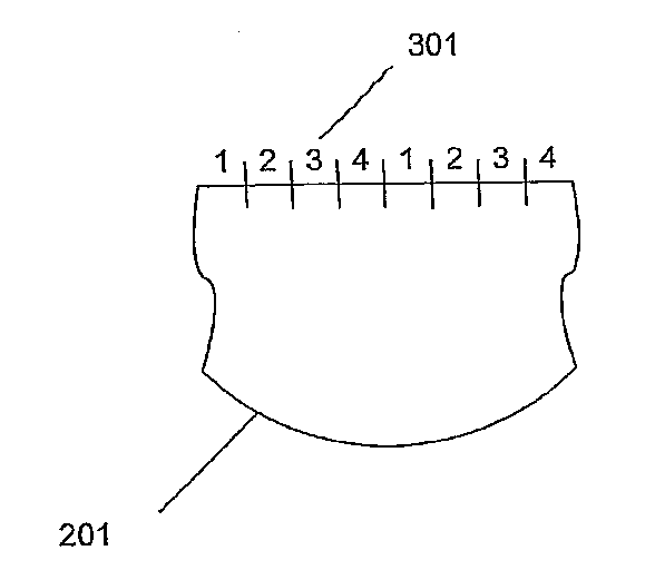
일부 필자들이 인터리빙(interleaving) 및 인터지깅(Interzigging)(StereoGraphics Corp. 회사에 의해 이용되는 용어)이라 부르는 용어 인터디지테이션은 복수의 투시 뷰들이 샘플링된 다음 단일의 이미지 파일로 매핑되는 처리이다. 가장 간단한 형태로, Hess의 미국 특허 제1,128,979호에 설명된 바와 같이, 좌측 및 우측 이미지가 렌티큘러 스크린 뒤의 병치(juxtaposition)를 위하여 광학적으로 수직방향으로 슬라이스되거나 교대된다. 전형적인 하드카피의 광학적 생성 파노라마그램(여기서 많은 뷰들이 존재함)에서, 각각의 뷰는 샘플링되고 각각의 수직 상태(vertical-going)의 렌티큘 뒤에 이미지 스트라이프들로 배열된다. 이러한 유형의 렌티큘러 스크린이 도 1a에 도시되어 있다. 스트라이프들의 반복하는 투시 뷰 배열이 컬럼이며, 한 컬럼은 수직 상태의 렌티큘과 동일한 폭을 갖고 바로 뒤에 있게 된다. 컴퓨터 인터디지테이션에 대하여 스트라이프 및 컬럼 설명은 간단하다. 도 1b의 것과 같이 Winnek 렌즈 어레이를 이용하는 경우 필요에 따라 보다 복잡한 매핑이 요구될 수 있다. 본 설계는 도 2a 및 도 3a 부분(202 및 301)에 대한 스트라이프 및 컬럼 설명을 채택한다. The term interdigitation, which some authors call interleaving and interzigging (the term used by the StereoGraphics Corp. company), is the process by which multiple perspective views are sampled and then mapped into a single image file. In its simplest form, the left and right images are optically vertically sliced or alternated for juxtaposition behind the lenticular screen, as described in Hess US Pat. No. 1,128,979. In a typical hardcopy optically generated panoramic diagram (where there are many views), each view is sampled and arranged into image stripes after each vertical-going lenticule. This type of lenticular screen is shown in FIG. 1A. The repeating perspective view array of stripes is a column, with one column immediately behind and having the same width as the vertical lenticules. Striping and column descriptions are simple for computer interdigitation. In the case of using the Winnek lens array as shown in FIG. 1B, more complicated mapping may be required as necessary. This design adopts the stripe and column descriptions for FIGS. 2A and
도 1은 반원통형 또는 코르덴(corduroy)형의 구조체(103)로 구성된 렌티큘러 디스플레이(101A)를 나타낸다. 렌티큘러 디스플레이(101A)의 뒷면은 전자 디스플레이(101)를 향하고 있다. 전자 디스플레이 표면(101)은 통상적으로 플랫 패널 디스플레이이다. 렌티큘(102)의 피치는 화살표들 내에 놓여있는 P로 도시된 렌티큘의 폭으로 정의될 수 있다. 반원통부의 바운더리 또는 교선(intersection)은 상호 평행하고 디스플레이(101)의 수직 에지들과 평행하며, 여기서 디스플레이는 전형적으로 직사각형 형상을 갖는다. 1 shows a lenticular display 101A composed of a semi-cylindrical or
도 1b는 이러한 방식에 대한 변형예를 나타내며, 미국 특허 제3,409,351호에 도시된 바와 같이 Winnek의 설계를 채용한 것이다. 상호 평행한 상태에 있는 반원 통부들의 교선 바운더리는 디스플레이의 수직 에지와 평행하지 않고 포인트(112)에 도시된 바와 같은 각도로 기울어져 있다. 이러한 사선 상태(diagonal-going)의 렌즈 시트(113)는 플랫 패널 디스플레이(101)와 관련되어 있다. 일반화의 손실없이, 여기에 도시된 기술은 표준 수직 상태 렌티큘러 어레이, Winnek 사선 상태 어레이, 또는 수직 상태 배향 또는 Winnek 교시에 따르는 래스터 배리어 어레이에 적용한다. FIG. 1B shows a variation on this approach and employs the design of Winnek as shown in US Pat. No. 3,409,351. The intersection boundary of the semicircular cylinders in parallel to each other is not parallel to the vertical edge of the display and is inclined at an angle as shown at
도 2a는 렌티큘에 의해 이미징되는 개별적인 투시 뷰들을 나타내기 위해 1,2,3,4로 라벨링된 스트라이프들의 단면과 함께 단일의 렌티큘(201)의 단면과, 디스플레이 이미지 컬럼(202)의 관련된 부분을 나타낸다. 어떠한 갯수의 뷰들이 채용될 수 있지만 설명의 간략화를 위해 4개가 제공된다. 도 2a의 설계는 수직 상태 렌티큘, Winnek 사선형 렌즈 시트 및 또한 수직 상태형 또는 Winnek 사선형일 수 있는 래스터 배리어 선택 장치 모두에 적용한다. 설명의 간략화를 위하여, 도면은 정확한 비례 관계로 도시하지 않는다. 일부 경우, 설명을 용이하게 하기 위해 과장 또는 간략화가 이루어진다. FIG. 2A shows the cross section of a
도 2b는 렌즈 시트(208)에 의해 커버되는 전자 디스플레이 패널(203)을 나타내며, 렌즈 시트(208)는 도 2a에 의해 주어지는 다수의 개별적인 렌티큘러 소자들로 구성된다. 디스플레이 앞의 공간은 1차 조망 구역(204)을 포함하며, 이 1차 조망 구역의 각도 범위는 ![]()
![]()
설명의 간략화를 위해서, 2차, 3차, 및 다른 주변 조망 구역은 상술한 바와 같은 특징들을 갖기 때문에 여기에서 설명하지 않는다. 여기에 설명되어 있는 설계 양태 및 광학적 현상이 이들 구역에 적용하며 1차 조망 구역의 각도 범위가 변화하는 경우 주변 구역이 비례적으로 변화한다. 4개의 투시 뷰들이 포인트 207에서의 조망 공간에서 펼쳐지는 상태로 도시되어 있으며, 각각의 뷰는 도 2a에서 포인트 202에 의해 도시되는 투시 뷰들에 대응한다. 한정된 화소 구조체를 갖는 전자 디스플레이가 채용되기 때문에, 투시 뷰들은 화소 또는 부화소(sub-pixel)의 집합체로 구성될 수 있다. 각각의 뷰들은 공간에서 펼쳐지는 다소의 수직 슬라이스로 발생한다. 도 3b의 평면도는 파이의 조각 형태로 슬라이스된 구역을 나타내며, 투시 서브섹션들이 왼쪽에서 오른쪽으로 진행하는 4, 3, 2 및 1로 라벨링된다. 서브섹션에 대한 방향 변화는 렌티큘(201)이 투시(202)를 광학적으로 반전시키기 때문에 일어난다. For simplicity of explanation, the secondary, tertiary, and other peripheral viewing zones have the features as described above and are not described herein. The design aspects and optical phenomena described herein apply to these zones and the surrounding zone changes proportionally when the angular range of the primary viewing zone changes. Four perspective views are shown unfolding in the viewing space at point 207, each view corresponding to the perspective views shown by
205에 의해 주어지는 양쪽 눈은 포인트 206에서 보다 먼 거리로 도시되어 있다. 눈동자간 거리는 양쪽 눈에 대한 거리와 동일하며, t로 주어진다. 도 3b로부터, 스테레오 뷰를 보기 위하여 조망 구역을 불규칙하게 퍼지게 하는 것이 필요하다. 예로서, 뷰(2 및 3)는 포인트 205에서의 관찰자에 대한 것이다. 관찰자가 포인트 206에 의해 지시된 거리에서 충분히 멀리 떨어져 있다면, 이 경우 스트라이프 3에 의해 표시된 바와 같이, 관찰자의 눈이 단일의 스트라이프의 범위 내에 있기 때문에 우측 및 좌측 눈은 투시 차이를 볼 수 없다. Both eyes given by 205 are shown at a greater distance at
어떤 최적의 범위들이 파노라마그램을 조망하기 위한 것이 되고, 관찰자가 렌즈 시트(208)를 갖는 디스플레이(203)로부터 추가로 멀리 떨어져 이동할 때, 스테레오페어를 볼 기회가 감소된다. 관찰자가 디스플레이에 보다 가까이 있게 될 때, 보여지는 스테레오페어를 구성하는 뷰들은, 관찰자가 디스플레이로부터 멀리 있을 때 부여되는 것보다 큰 축간 간격으로 생성된다. 따라서, 범위 내에서 디스플레이에 가까이 있는 것은 강한 스테레오스코픽 효과를 제공하고, 역으로, 디스플레이로부터 멀리 떨어져 있는 것은 감소된 스테레오스코픽 효과를 제공한다. 극단적인 경우에는, 포인트 206을 기준으로 인식될 수 있는 바와 같이, 스테레오스코픽 효과가 존재하지 않는다. 구역이 넓을수록, 고정값(t)으로 주어진 투시 뷰들이 더 멀리 떨어진 것으로 인식하기 때문에 스테레오스코픽 효과는 또한 조망 구역의 각도 범위 함수이다. 이와 반대로, 보여지는 투시 뷰들이 더 먼 거리로부터 찍혀지거나 캡쳐링되기 때문에 구역의 범위가 좁을수록 더 깊은 이미지가 나타난다. 스테레오스코픽 효과의 강도는 스테레오페어의 축간 간격의 함수 또는 발생되거나 캡쳐링된 이미지들 간의 거리의 함수이다.Some optimal ranges are for viewing the panoramagram, and as the viewer moves further away from the
본 설계는 관찰자가 가까운 거리에 위치해 있을 때 보여질 수 있는 것과 동일한 뷰들을 관찰자가 디스플레이로부터 먼 거리에서 왼쪽 눈과 오른쪽 눈으로 볼 수 있게 한다. The design allows the viewer to see the left and right eyes at a distance from the display, the same views that can be seen when the observer is located at close range.
도 3a 및 도 3b는 스테레오 효과의 강도 또는 "pop"가 증가하는 것을 그래픽적으로 나타낸 것이다. 한 접근 방법은 렌즈 시트를 변경하거나 교환하는 것이다. 렌티큘들의 초점 길이 또는 초점 길이들을 증가시키는 것은 조망 구역(204)의 각도 범위(![]()
![]()
도 3b는 이러한 반복의 이용이 조망 구역의 각도 범위를 반으로 나눔으로써, 포인트 304에서의 각도(![]()
![]()
포인트 206에서 도 2b에 도시된 것과 동일한 거리에 위치된 관찰자(305)는 현재 도 2b에서 이용가능한 것보다 더 큰 축간 간격을 갖는 포인트 306에서의 투시 뷰들을 보는 능력을 갖는다. 도 3b에 도시된 예에서, 도 2b와 비교하여, t로 고정된 눈동자간 간격을 갖는 관찰자는 현재 단순히 뷰 3 보다는 각각의 뷰 3과 2를 본다. 이것은 현재 스테레오스코픽 뷰의 인식을 가져온다. 이러한 특정예는 비스테레오스코픽 조망에서 스테레오스코픽 조망으로 개선이 진행하는 극단적인 경우이다. 동일한 효과가 더 멀리 떨어진 투시 뷰들을 보는 관찰자에 대하여 적용한다. 예를 들어, 주어진 거리에서 관찰자가 뷰 3과 2를 보는 경우, 여기에 교시된 것과 같은 구역의 각도 범위에서의 감소와 함께, 관찰자는 그가 보다 깊은 스테레오스코픽 이미지를 보고 있는 결과로서 뷰 4와 1을 볼 수 있다. The
동일한 원리가 2차, 3차 및 다른 주변 조망 구역에 대하여 유효하다. 본 설계는 패턴을 3번 반복하는 것(예를 들어, 1,2,3,4,1,2,3,4,1,2,3,4) 또는 사실상 n번 반복하는 것을 포함할 수 있다. 투시 뷰들의 패턴을 반복하고 조망 구역의 각도 범위를 감소시키며, 따라서 스테레오스코픽 효과를 증가시키는 능력은 디스플레이의 분해능에 의해서만 제한받는다. 패턴을 반복하는 것은 관찰자가 디스플레이로부터 보다 멀리 떨어져 강한 스테레오스코픽 효과를 볼 수 있게 한다. 디스플레이로부터 비교적 멀리 떨어진 관찰자는 분해능에서의 감소를 일으켜, 이미지가 거의 보여질 수 없게 된다. The same principle is valid for secondary, tertiary and other surrounding viewing areas. The design may include repeating the pattern three times (eg, 1,2,3,4,1,2,3,4,1,2,3,4) or in fact repeating n times. . The ability to repeat the pattern of perspective views and reduce the angular range of the viewing area, thus increasing the stereoscopic effect is limited only by the resolution of the display. Repeating the pattern allows the viewer to see a stronger stereoscopic effect farther from the display. Observers relatively far from the display cause a decrease in resolution, making the image hardly visible.
본 설명은 이러한 4개의 뷰들의 이용을 제공하며, 실제의 경우에는 이러한 제한은 없다. 9개, 16개, 또는 다른 갯수의 뷰들을 포함한 어떠한 갯수의 뷰들이 채용될 수 있다. 또한, 굴절형 또는 렌티큘러 디스플레이의 경우에 대하여 여기에 설명되어 있지만, 이러한 과정은 래스터 배리어에도 또한 적용한다. 또한, 본 설계가 개별적인 렌티큘로 발생하는 것을 도시하는 것에 의해 설명되어 있지만, 한 렌티큘이 수천개의 렌티큘을 포함할 수 있는 전체 렌즈 시트 하에서의 액티비티들을 간단하게 대표한다. The description provides for the use of these four views, and in practice there is no such limitation. Any number of views may be employed, including nine, sixteen, or other numbers of views. Furthermore, while the case of articulated or lenticular displays is described herein, this procedure also applies to raster barriers. In addition, while the present design is described by showing what occurs with individual lenticules, one lenticule simply represents activities under the entire lens sheet that may include thousands of lenticules.
본 설계는 이에 한정되는 것은 아니지만 2560 × 1600 화소들의 분해능을 갖는 대각 길이가 30인치인 디스플레이 스크린을 가진 애플 시네마 모니터를 포함하는 복수의 디스플레이들 및/또는 장치들의 어느 것에서도 구현될 수 있다. 이 모니터의 분해능은 당대 표준에 의한 크기이며, 투시 패턴을 반복하기에 충분한 렌티큘 하에서의 화소들을 허용한다. 이러한 구성에서, 0.090 인치 정도의 것과 같이 상대적으로 얇은 유리 기판이 채용될 수 있으며, 유리 기판 위에 0.80 mm 정도의 피치를 갖는 렌티큘들이 주조될 수 있다. StereoGraphics Corporation 회사에 의한 Interzig와 같은 독점적인 인터디지테이션 알고리즘 또는 다른 인터디지테이션 알고리즘이 채용될 수 있다. Interzig는 상술한 바와 같이 Winnek형 렌즈 시트의 광학을 고려한다. The design may be implemented in any of a plurality of displays and / or devices including, but not limited to, an Apple Cinema Monitor with a diagonal 30 inch display screen with a resolution of 2560 by 1600 pixels. The resolution of this monitor is the size of the current standard, allowing pixels under lenticules to repeat the perspective pattern. In this configuration, a relatively thin glass substrate can be employed, such as on the order of 0.090 inches, and lenticules with a pitch on the order of 0.80 mm can be cast over the glass substrate. Proprietary interdigitation algorithms such as Interzig by StereoGraphics Corporation, or other interdigitation algorithms may be employed. Interzig considers the optics of a Winnek type lens sheet as described above.
이러한 종류의 사선형(slanted) 배열을 이용하는 경우, 뷰들은 디스플레이의 수평 에지에 평행하게 나아가는 컬러 및 투시 스트라이프들을 포함한 로우에 매핑될 뿐만 아니라, 뷰들은 컬럼 내에서 수직 방향으로 또는 실제적으로 대각선 방향으로 배열된다. 9개의 투시 뷰 이미지 그룹과 같이 복수의 뷰 투시 이미지 그룹이 채용될 수 있다. 통상의 수직 상태의 파노라마그램에 대하여, 컬럼 내에서의 9개의 스트라이프들이, 단일의 렌티큘 바로 밑의 컬럼 내에서 로우를 따라 스트라이프들이 진행하는(1에서 9까지 진행) 설계에 제공된다. With this kind of slanted arrangement, the views are not only mapped to rows containing color and perspective stripes that run parallel to the horizontal edge of the display, but also the views are vertically or substantially diagonally within the column. Are arranged. Multiple view perspective image groups may be employed, such as nine perspective view image groups. For a typical vertical panoramic diagram, nine stripes in a column are provided in a design where the stripes travel along a row (going from 1 to 9) in a column just below a single lenticule.
Winnek 배열에서, 이미지 그룹은 상술한 원리들이 여전히 적용하는 렌티큘 하에서 수개의 로우들을 점유한다. 본 설명은 교시(didactic) 목적을 위하여 수직 상태 렌티큘러 바운더리를 갖는 통상의 파노라마그램을 채용하지만, 애플리케이션에 의존하여 어떤 추가의 복잡성이 해결되는 것이 필요할 수 있다. 뷰들이 각각의 렌티큘 하에서 컬럼 단위 기반으로 한 로우에 점진적으로 배열되고 컬럼이 로우 하에서 스트라이프들 내에 인터디지테이션되는 투시들에 의해 형성되든, 또는 투시 뷰들이 Winnek 배열에 의해 요구되는 보다 복잡한 방식으로 배열되든지 간에, 이 설계에 대한 전반적인 원리가 복수의 투시 뷰들을 제공하며, 여기서는, 제한된 갯수의 투시 뷰들이 이미 제공되었다. 플랫 패널 디스플레이에 대하여, 화소들은 적색, 녹색, 청색 부화소의 클러스터들로 구성된다. 이 설계는 Interzig 매핑 알고리즘과 같은 인터디지테이션 알고리즘이 부화소 형태(manifestation)에 기초한 값들을 고려하여 연산하기 때문에 보다 복잡해지기 쉽다. In a Winnek arrangement, an image group occupies several rows under a lenticule to which the principles described above still apply. Although this description employs a conventional panoramic diagram with vertical lenticular boundaries for teaching purposes, it may be necessary to address some additional complexity depending on the application. Whether views are formed by perspectives that are progressively arranged in a row on a column-by-column basis under each lenticular and the column is interdigitated in stripes under the row, or in a more complex manner where perspective views are required by the Winnek array. Whether arranged, the overall principle for this design provides a plurality of perspective views, where a limited number of perspective views have already been provided. For a flat panel display, the pixels are composed of clusters of red, green and blue subpixels. This design is more complex because interdigitation algorithms, such as the Interzig mapping algorithm, operate on values based on subpixel manifestations.
본 설계의 일 구현예는 대략 3.204의 렌티큘당 화소(P/L) 배열을 이용한다. 이것은 렌티큘 하에서 컬럼 내에 9개의 뷰들을 제공한다. P/L 비값을 대략 1.602로 변경하는 것은 1...9, 1...9의 충분한 패턴으로 각각의 렌티큘 하에서 18개의 뷰들을 제공한다. 조망 구역은 각도 범위에서 반으로 나누어졌고, 먼 거리에서 조망되었을 때 깊이 효과는 크게 강화되었다. 특히, 대략 3.204에서의 P/L에서는, 약 5 내지 15 피트에서 10도의 각도 범위의 조망 구역 내에서 양호한 스테레오스코픽 이 미지가 조망될 수 있다. 1차 구역에 더하여, 양호한 2차, 3차 구역 및 2개의 추가적인 외부 구역들이 적당한 조망을 위하여 총 7개의 양호한 조망 구역을 제공한다. P/L을 대략 1.602로 반으로 나누는 것은 15 피트를 초과하여도 양호한 스테레오 뷰를 제공할 수 있다. 본 설계를 이용하여 양호한 조망 구역의 갯수가 증가한다. One implementation of this design uses an array of pixels per lenticular (P / L) of approximately 3.204. This gives nine views in the column under the lenticule. Changing the P / L ratio to approximately 1.602 provides 18 views under each lenticle with sufficient patterns of 1 ... 9, 1 ... 9. The viewing zone was divided in half in the angular range, and the depth effect was greatly enhanced when viewed from a distance. In particular, at a P / L of approximately 3.204, a good stereoscopic image can be viewed within the viewing zone in an angular range of about 5 to 15 feet to 10 degrees. In addition to the primary zone, good secondary, tertiary zones and two additional exterior zones provide a total of seven good viewing zones for proper viewing. Dividing P / L in half by approximately 1.602 can provide a good stereo view even greater than 15 feet. Using this design, the number of good viewing zones is increased.
구역의 뷰의 범위가 반으로 나누어진다는 점에도 불구하고, 헤드 박스, 또는 새로운 구역 내에서의 허용가능한 머리 움직임의 수평 범위가 크며, 용이한 조망을 허용한다. 관찰자는 디스플레이의 평면에 근접하여 꼭지점을 갖는 이등변 삼각형을 형성하는 조망 구역을 상상할 수 있다. 디스플레이의 표면에 평행하고 또한 디스플레이의 수평 에지에 평행한 평면 내에 포함되어 있는 선에 의해 측정된 조망 구역 폭은 스크린으로부터의 거리에 대략적으로 비례한다. 구역의 각도 범위가 반으로 감소된 경우에, 조망 거리를 두배로 하는 것은 대략 동일한 구역 폭을 가져올 수 있다. 이러한 경우, 관찰자가 보다 먼 거리에 있는 경우에도 (구역 내에서 좌우로의 또는 측방향으로의 위치에 의존하여) 동일한 투시 스트라이프들이 관찰될 수 있다. 따라서, 스테레오스코픽 깊이 효과가 보다 먼 전체 거리에 대하여 유지된다. 렌티큘 하에서의 이미지의 분해능이 반으로 나누어진다는 점에도 불구하고, 이러한 설계를 이용한 이미지들은 비교적 선명하게 보여지기 쉽다. 디스플레이로부터 상당히 멀리 위치되어 있는 관찰자는 이미지 형성에 이용가능한 화소의 갯수들에 의해 결정되는 분해능에서의 감소를 보상할 수 있다. Despite the fact that the range of the view of the zone is divided in half, the horizontal range of acceptable head movements within the head box, or new zone, is large, allowing easy viewing. The observer can imagine a viewing area that forms an isosceles triangle with vertices close to the plane of the display. The viewing area width measured by the line included in the plane parallel to the surface of the display and parallel to the horizontal edge of the display is approximately proportional to the distance from the screen. If the angular range of the zone is reduced by half, doubling the viewing distance can result in approximately the same zone width. In this case, the same perspective stripes can be observed (depending on the position from side to side or side to side within the zone) even when the viewer is at a greater distance. Thus, the stereoscopic depth effect is maintained over the farther overall distance. Despite the fact that the resolution of an image under lenticular is divided in half, images using this design tend to be relatively sharp. An observer who is located quite far from the display can compensate for the reduction in resolution determined by the number of pixels available for image formation.
보다 먼 거리로부터 깊이를 인식하는 능력의 확장 뿐만 아니라, 여기에서 제공되는 설계는, 조망 구역 각도 범위에서의 감소가 구역 범위 감소 이전 보다 더 큰 축간 간격을 갖는 눈에 대한 스테레오페어를 제공하는 효과를 가지기 때문에 또한 통상의 조망 거리 범위 내에서의 깊이 효과를 증가시키는데 이용될 수 있다. In addition to the extension of the ability to perceive depth from greater distances, the design provided herein has the effect that the reduction in the viewing zone angle range provides a stereo pair for eyes with larger interaxial spacing than before the zone range reduction. As such, it can also be used to increase the depth effect within the normal viewing distance range.
따라서, 소프트웨어에서 인터디지테이션 상수들을 변경하는 것은 렌즈 시트의 각각의 렌티큘 하에서 투시 뷰들의 반복하는 패턴을 제공할 수 있고, 이러한 방법에 의해, 뷰어가 예를 들어, 디스플레이로부터 자신의 원래 거리의 두배인 거리에 있는 경우 스테레오스코픽 효과에서의 수반하는 증가와 함께 뷰의 각도가 반으로 나누어질 수 있다. 이러한 방식으로, 단거리로부터 즐겁게 조망되는 동일한 오토스테레오스코픽 디스플레이가, 먼 거리로부터 증가된 스테레오스코픽 깊이 효과를 가지도록 형성될 수 있다. Thus, changing the interdigitation constants in software can provide a repeating pattern of perspective views under each lenticule of the lens sheet, whereby the viewer can, for example, of its original distance from the display. At twice the distance, the angle of view can be divided in half with the accompanying increase in stereoscopic effect. In this way, the same autostereoscopic display that is pleasantly viewed from a short distance can be formed to have an increased stereoscopic depth effect from a long distance.
여기에서 반영된 일반 설계는 도 4에 도시되어 있다. 일반적으로, 소프트웨어는 반드시 필요한 것은 아니지만, 포인트 401에서 기준선 프로파일을 설정할 수 있는데, 기준선 프로파일은 단일의 렌티큘 바로 밑에 제공되는 뷰들의 갯수를 나타낸다. 상술한 예들 중 한 예에서, 뷰 1,2,3,4가 제공된다. 포인트 402는 뷰들의 갯수를 두배로 하거나 그렇지 않으면 뷰들의 갯수를 인수만큼 곱함으로써 예를 들어, 뷰 1,2,3,4,1,2,3,4,1,2,3,4가 동일한 렌티큘 바로 밑에 있게 되는 것과 같이, 렌티큘 바로 밑에 제공되는 뷰들의 갯수를 증가시키는 것을 나타낸다. 그 후, 이렇게 제공된 값 또는 뷰들은 포인트 403에서 인터디지테이션 처리 또는 프로그램에 적용된다. 범용 프로세서 또는 컴퓨팅 장치가 기준선, 예상되는 기준선, 또는 일반적으로 이해되는 뷰들의 갯수에 기초하여 각각의 렌티큘 바로 밑에 제공되는 뷰들의 갯수를 설정할 수 있고, 전송되어질 뷰들의 증가된 갯수를 연산할 수 있다. 그 후, 프로세서는 렌티큘 당 뷰들의 갯수 및 실제 뷰들의 갯수를 인터디지테이션 프로그램에 전달할 수 있거나 또는 메모리 장치 또는 다른 적절한 장치 또는 회로를 편입(enlist)하여 연산된 뷰들의 갯수를 StereoGraphics Corporation 회사의 독점 소프트웨어의 경우의 인터지깅 또는 인터디지테이션을 위한 인터디지테이션 처리 장치 또는 모듈에 제공할 수 있다. The general design reflected here is shown in FIG. 4. In general, the software is not required, but can set a baseline profile at
이러한 설계를 살펴보는 다른 방법은 설계가 서로 관련되어 있는 제1 양의 데이터 컬럼들을 갖는 디스플레이로부터 수신되는 파노라마그램 조망 구역의 각도 범위를 변경하는 능력을 제공하는 것이다. 본 설계는 서로 관련되어 있는 기준선 갯수의 뷰들을 갖는 제1 데이터 컬럼을 제공한다. 제1 데이터 컬럼은 디스플레이와 관련된 렌즈 시트에서의 하나 이상의 렌티큘에 제공된다. 본 설계는 하나 이상의 렌티큘에 제1 양의 데이터 컬럼으로부터 변경된 제2 양의 데이터 컬럼을 제공하는 것을 더 포함한다. 제2 양의 데이터 컬럼은 기준선 갯수의 뷰들보다 더 많은 뷰들을 포함한다. 오토스테레오스코픽 이미지를 구성하는 경우에 제2 양의 데이터 컬럼을 채용하는 것은 특정한 뷰 거리에 대하여 오토스테레오스코픽 이미지의 비교적 선명한 조망을 갖는 디스플레이를 제공한다. Another way to look at such a design is to provide the ability to change the angular range of the panoramicgram viewing area that is received from the display having the first positive data columns with which the design is related. The design provides a first data column having a baseline number of views that are related to each other. The first data column is provided to one or more lenticules in the lens sheet associated with the display. The design further includes providing a second amount of data column changed from the first amount of data column to the one or more lenticules. The second amount of data column includes more views than the baseline number of views. Employing a second amount of data columns in constructing an autostereoscopic image provides a display with a relatively clear view of the autostereoscopic image for a particular viewing distance.
여기에 설명된 장치, 처리 및 특징은 다른 장치, 처리 및 특징을 배제하는 것이 아니며, 다른 수정 및 부가예들이 달성될 특정 목적에 따라 구현될 수 있다. 예를 들어, 여기에 설명된 장치 및 처리가 여기에 설명되지 않은 다른 장치 및 처리와 통합되거나 또는 상호작용하여, 특징들의 추가 조합을 제공하거나, 또는 동일한 장치 내에서 동시에 동작하거나 또는 다른 목적을 지원할 수 있다. 따라서, 도 면에서 도시되고 위에서 설명된 실시예들은 단지 예에 의해 제공되는 것으로 이해되어야 한다. 본 발명은 특정 실시예로 제한되지 않으며, 청구범위 및 그 등가물의 범위 내에 있는 여러 변형, 결합 및 조합으로 확장한다. The devices, processes, and features described herein are not exclusive of other devices, processes, and features, and other modifications and additions may be implemented depending on the specific purpose for which they are to be achieved. For example, the devices and processes described herein may integrate or interact with other devices and processes not described herein to provide additional combinations of features, operate simultaneously within the same device, or support other purposes. Can be. Accordingly, it should be understood that the embodiments shown in the drawings and described above are provided by way of example only. The invention is not limited to the specific embodiments, but extends to various modifications, combinations and combinations that fall within the scope of the claims and their equivalents.
여기에 제공된 설계 및 설명된 특정 양태들은 제한적인 것으로 의미되지 않으며, 본 발명의 교시 및 이점을 여전히 포함하면서 대체의 구성요소들을 포함할 수 있다. 따라서 본 발명이 특정 실시예와 결합하여 설명되어 있지만, 본 발명은 추가 변경을 할 수 있다. 본 출원은 본 발명이 속하는 기술 내에서의 공지의 및 통례의 실시 내에 오는 본 발명의 개시로부터의 이탈을 포함하고 일반적으로 본 발명의 원리들을 따르는 본 발명의 어떠한 변형, 이용 또는 적응도 포함하는 것으로 의도된다. The specific aspects presented and described herein are not meant to be limiting and may include alternative components while still incorporating the teachings and advantages of the present invention. Thus, while the invention has been described in conjunction with specific embodiments, the invention may be further modified. This application is intended to cover departures from the teachings of this invention that come within the known and customary practice within the art to which this invention pertains and generally encompass any modification, use or adaptation of the invention in accordance with the principles of the invention. It is intended.
특정 실시예들의 상술한 설명은 일반적인 개념에 벗어남이 없이 다른 사람이 현재의 지식을 적용하여 여러 애플리케이션에 대한 시스템 및 방법을 쉽게 변형 및/또는 적응시킬 수 있는 개시의 일반 특성을 충분히 드러낸다. 따라서, 이러한 적응 및 변형은 개시된 실시예의 등가물의 의미와 범위 내에 있다. 여기에 채용된 어구 또는 용어는 설명을 위한 것이며 제한을 위한 것이 아니다. The foregoing description of specific embodiments fully reveals the general nature of the disclosure in which others may readily adapt and / or adapt systems and methods for various applications by applying current knowledge. Accordingly, such adaptations and modifications are within the meaning and range of equivalents of the disclosed embodiments. The phraseology or terminology employed herein is for the purpose of description and not of limitation.
Claims (20)
Applications Claiming Priority (2)
| Application Number | Priority Date | Filing Date | Title |
|---|---|---|---|
| US68810005P | 2005-06-07 | 2005-06-07 | |
| US60/688,100 | 2005-06-07 |
Publications (2)
| Publication Number | Publication Date |
|---|---|
| KR20080036018A KR20080036018A (en) | 2008-04-24 |
| KR101265893B1 true KR101265893B1 (en) | 2013-05-20 |
Family
ID=37499059
Family Applications (1)
| Application Number | Title | Priority Date | Filing Date |
|---|---|---|---|
| KR1020077030637A Expired - Fee Related KR101265893B1 (en) | 2005-06-07 | 2006-06-06 | Controlling the angular extent of autostereoscopic viewing zones |
Country Status (5)
| Country | Link |
|---|---|
| US (1) | US8049962B2 (en) |
| EP (1) | EP1889123B1 (en) |
| JP (1) | JP5465430B2 (en) |
| KR (1) | KR101265893B1 (en) |
| WO (1) | WO2006133224A2 (en) |
Cited By (1)
| Publication number | Priority date | Publication date | Assignee | Title |
|---|---|---|---|---|
| KR102070935B1 (en) | 2019-01-09 | 2020-01-29 | 이동현 | Multifunctional chair and method of controlling the same |
Families Citing this family (52)
| Publication number | Priority date | Publication date | Assignee | Title |
|---|---|---|---|---|
| GB0522968D0 (en) | 2005-11-11 | 2005-12-21 | Popovich Milan M | Holographic illumination device |
| GB0718706D0 (en) | 2007-09-25 | 2007-11-07 | Creative Physics Ltd | Method and apparatus for reducing laser speckle |
| US9335604B2 (en) | 2013-12-11 | 2016-05-10 | Milan Momcilo Popovich | Holographic waveguide display |
| US11726332B2 (en) | 2009-04-27 | 2023-08-15 | Digilens Inc. | Diffractive projection apparatus |
| TW201216684A (en) * | 2010-10-12 | 2012-04-16 | Unique Instr Co Ltd | Stereoscopic image display device |
| JP5695395B2 (en) | 2010-11-19 | 2015-04-01 | インターナショナル・ビジネス・マシーンズ・コーポレーションInternational Business Machines Corporation | Stereoscopic image generation method and apparatus |
| US9274349B2 (en) | 2011-04-07 | 2016-03-01 | Digilens Inc. | Laser despeckler based on angular diversity |
| BR112013032590A2 (en) * | 2011-06-22 | 2017-01-17 | Koninkl Philips Nv | auto stereoscopic display device |
| CN103733118B (en) * | 2011-08-11 | 2015-11-25 | 富士通株式会社 | Stereoscopic image display device |
| WO2016020630A2 (en) | 2014-08-08 | 2016-02-11 | Milan Momcilo Popovich | Waveguide laser illuminator incorporating a despeckler |
| US10670876B2 (en) | 2011-08-24 | 2020-06-02 | Digilens Inc. | Waveguide laser illuminator incorporating a despeckler |
| WO2013027004A1 (en) | 2011-08-24 | 2013-02-28 | Milan Momcilo Popovich | Wearable data display |
| WO2013102759A2 (en) | 2012-01-06 | 2013-07-11 | Milan Momcilo Popovich | Contact image sensor using switchable bragg gratings |
| JP6238965B2 (en) | 2012-04-25 | 2017-11-29 | ロックウェル・コリンズ・インコーポレーテッド | Holographic wide-angle display |
| WO2013167864A1 (en) | 2012-05-11 | 2013-11-14 | Milan Momcilo Popovich | Apparatus for eye tracking |
| JP2014045466A (en) * | 2012-08-29 | 2014-03-13 | Lenovo Singapore Pte Ltd | Stereoscopic video display system, setting method and observation position changing method of stereoscopic video data |
| US9933684B2 (en) | 2012-11-16 | 2018-04-03 | Rockwell Collins, Inc. | Transparent waveguide display providing upper and lower fields of view having a specific light output aperture configuration |
| WO2014188149A1 (en) | 2013-05-20 | 2014-11-27 | Milan Momcilo Popovich | Holographic waveguide eye tracker |
| US9727772B2 (en) | 2013-07-31 | 2017-08-08 | Digilens, Inc. | Method and apparatus for contact image sensing |
| WO2016020632A1 (en) | 2014-08-08 | 2016-02-11 | Milan Momcilo Popovich | Method for holographic mastering and replication |
| US10241330B2 (en) | 2014-09-19 | 2019-03-26 | Digilens, Inc. | Method and apparatus for generating input images for holographic waveguide displays |
| WO2016046514A1 (en) | 2014-09-26 | 2016-03-31 | LOKOVIC, Kimberly, Sun | Holographic waveguide opticaltracker |
| CN111323867A (en) | 2015-01-12 | 2020-06-23 | 迪吉伦斯公司 | Environmentally isolated waveguide display |
| EP3245551B1 (en) | 2015-01-12 | 2019-09-18 | DigiLens Inc. | Waveguide light field displays |
| JP6867947B2 (en) | 2015-01-20 | 2021-05-12 | ディジレンズ インコーポレイテッド | Holographic waveguide rider |
| US9632226B2 (en) | 2015-02-12 | 2017-04-25 | Digilens Inc. | Waveguide grating device |
| US10459145B2 (en) | 2015-03-16 | 2019-10-29 | Digilens Inc. | Waveguide device incorporating a light pipe |
| WO2016156776A1 (en) | 2015-03-31 | 2016-10-06 | Milan Momcilo Popovich | Method and apparatus for contact image sensing |
| JP6598269B2 (en) | 2015-10-05 | 2019-10-30 | ディジレンズ インコーポレイテッド | Waveguide display |
| WO2017134412A1 (en) | 2016-02-04 | 2017-08-10 | Milan Momcilo Popovich | Holographic waveguide optical tracker |
| JP6895451B2 (en) | 2016-03-24 | 2021-06-30 | ディジレンズ インコーポレイテッド | Methods and Devices for Providing Polarized Selective Holography Waveguide Devices |
| US10890707B2 (en) | 2016-04-11 | 2021-01-12 | Digilens Inc. | Holographic waveguide apparatus for structured light projection |
| EP3548939A4 (en) | 2016-12-02 | 2020-11-25 | DigiLens Inc. | WAVE GUIDE DEVICE WITH UNIFORM OUTPUT LIGHTING |
| US10545346B2 (en) | 2017-01-05 | 2020-01-28 | Digilens Inc. | Wearable heads up displays |
| EP3698214A4 (en) | 2017-10-16 | 2021-10-27 | Digilens Inc. | SYSTEMS AND METHODS FOR MULTIPLE IMAGE RESOLUTION OF A PIXELED DISPLAY |
| WO2019136476A1 (en) | 2018-01-08 | 2019-07-11 | Digilens, Inc. | Waveguide architectures and related methods of manufacturing |
| KR20250027583A (en) | 2018-01-08 | 2025-02-26 | 디지렌즈 인코포레이티드. | Systems and methods for high-throughput recording of holographic gratings in waveguide cells |
| KR20250089565A (en) | 2018-01-08 | 2025-06-18 | 디지렌즈 인코포레이티드. | Systems and methods for manufacturing waveguide cells |
| US20190212699A1 (en) | 2018-01-08 | 2019-07-11 | Digilens, Inc. | Methods for Fabricating Optical Waveguides |
| CN119471906A (en) | 2018-03-16 | 2025-02-18 | 迪吉伦斯公司 | Holographic waveguides incorporating birefringence control and methods for their fabrication |
| US11402801B2 (en) | 2018-07-25 | 2022-08-02 | Digilens Inc. | Systems and methods for fabricating a multilayer optical structure |
| WO2020149956A1 (en) | 2019-01-14 | 2020-07-23 | Digilens Inc. | Holographic waveguide display with light control layer |
| US20200247017A1 (en) | 2019-02-05 | 2020-08-06 | Digilens Inc. | Methods for Compensating for Optical Surface Nonuniformity |
| US20220283377A1 (en) | 2019-02-15 | 2022-09-08 | Digilens Inc. | Wide Angle Waveguide Display |
| CN113692544B (en) | 2019-02-15 | 2025-04-22 | 迪吉伦斯公司 | Method and apparatus for providing holographic waveguide displays using integrated gratings |
| JP2022525165A (en) | 2019-03-12 | 2022-05-11 | ディジレンズ インコーポレイテッド | Holographic Waveguide Backlights and Related Manufacturing Methods |
| JP7765292B2 (en) | 2019-06-07 | 2025-11-06 | ディジレンズ インコーポレイテッド | Waveguides incorporating transmission and reflection gratings and related methods of manufacture |
| JP2022543571A (en) | 2019-07-29 | 2022-10-13 | ディジレンズ インコーポレイテッド | Method and Apparatus for Multiplying Image Resolution and Field of View for Pixelated Displays |
| CN114450608A (en) | 2019-08-29 | 2022-05-06 | 迪吉伦斯公司 | Vacuum Bragg grating and method of manufacture |
| EP4252048A4 (en) | 2020-12-21 | 2024-10-16 | Digilens Inc. | EYEGLOW SUPPRESSION IN WAVEGUIDE-BASED DISPLAYS |
| WO2022150841A1 (en) | 2021-01-07 | 2022-07-14 | Digilens Inc. | Grating structures for color waveguides |
| US12158612B2 (en) | 2021-03-05 | 2024-12-03 | Digilens Inc. | Evacuated periodic structures and methods of manufacturing |
Family Cites Families (50)
| Publication number | Priority date | Publication date | Assignee | Title |
|---|---|---|---|---|
| US1128979A (en) * | 1912-06-01 | 1915-02-16 | Walter Hess | Stereoscopic picture. |
| US1970311A (en) * | 1931-02-14 | 1934-08-14 | Bell Telephone Labor Inc | Projection of images for viewing in stereoscopic relief |
| US3409351A (en) * | 1966-02-07 | 1968-11-05 | Douglas F. Winnek | Composite stereography |
| US4740073A (en) * | 1982-12-27 | 1988-04-26 | Meacham G B Kirby | System for projecting three-dimensional images |
| US4542958A (en) * | 1983-01-13 | 1985-09-24 | Vasco, Ltd. | Variable aspect display |
| US4804253A (en) * | 1986-05-15 | 1989-02-14 | General Electric Company | Lenticular filter for display devices |
| US4807978A (en) * | 1987-09-10 | 1989-02-28 | Hughes Aircraft Company | Color display device and method using holographic lenses |
| JPH0418891A (en) * | 1990-05-14 | 1992-01-23 | Nippon Telegr & Teleph Corp <Ntt> | Stereoscopic display device |
| AU652051B2 (en) * | 1991-06-27 | 1994-08-11 | Eastman Kodak Company | Electronically interpolated integral photography system |
| JP2566087B2 (en) * | 1992-01-27 | 1996-12-25 | 株式会社東芝 | Colored microlens array and manufacturing method thereof |
| JP2746790B2 (en) * | 1992-03-02 | 1998-05-06 | 富士写真フイルム株式会社 | Stereoscopic image recording method and stereoscopic image recording apparatus |
| JPH05289208A (en) * | 1992-04-15 | 1993-11-05 | Fuji Photo Film Co Ltd | Method and device for recording stereoscopic image |
| US5278608A (en) * | 1992-05-19 | 1994-01-11 | Eastman Kodak Company | Electronically printed depth photography system with improved viewing range |
| JP3409810B2 (en) * | 1993-09-09 | 2003-05-26 | ソニー株式会社 | Image output method |
| US5581402A (en) * | 1993-11-22 | 1996-12-03 | Eastman Kodak Company | Method for producing an improved stereoscopic picture and stereoscopic picture obtained according to this method |
| US5588526A (en) * | 1994-04-01 | 1996-12-31 | Insight, Inc. | Flat box system with multiple view optics |
| US5933276A (en) * | 1994-04-13 | 1999-08-03 | Board Of Trustees, University Of Arkansas, N.A. | Aberration-free directional image window sheet |
| GB2297876A (en) * | 1995-02-09 | 1996-08-14 | Sharp Kk | Observer tracking autostereoscopic display |
| JPH08314034A (en) | 1995-05-18 | 1996-11-29 | Canon Inc | Stereoscopic image display method and device |
| JP3459721B2 (en) * | 1995-05-22 | 2003-10-27 | キヤノン株式会社 | Stereoscopic image display method and stereoscopic image display device using the same |
| JPH08327948A (en) | 1995-05-31 | 1996-12-13 | Canon Inc | Stereoscopic image display method and stereoscopic image display device |
| JPH0915532A (en) * | 1995-06-29 | 1997-01-17 | Canon Inc | Stereoscopic image display method and stereoscopic image display device using the same |
| GB9513658D0 (en) * | 1995-07-05 | 1995-09-06 | Philips Electronics Uk Ltd | Autostereoscopic display apparatus |
| US6064424A (en) | 1996-02-23 | 2000-05-16 | U.S. Philips Corporation | Autostereoscopic display apparatus |
| FR2748579B1 (en) * | 1996-05-09 | 1998-08-21 | Allio Pierre | AUTOSTEREOSCOPIC IMAGE FORMING DEVICE AND SYSTEM COMPRISING SAME |
| GB2321815A (en) * | 1997-02-04 | 1998-08-05 | Sharp Kk | Autostereoscopic display with viewer position indicator |
| GB2317771A (en) * | 1996-09-27 | 1998-04-01 | Sharp Kk | Observer tracking directional display |
| JP2001519126A (en) * | 1997-03-27 | 2001-10-16 | リットン・システムズ・インコーポレーテッド | Automatic stereoscopic projection system |
| GB9715397D0 (en) * | 1997-07-23 | 1997-09-24 | Philips Electronics Nv | Lenticular screen adaptor |
| US7239293B2 (en) * | 1998-01-21 | 2007-07-03 | New York University | Autostereoscopic display |
| DE19827590C2 (en) * | 1998-06-20 | 2001-05-03 | Christoph Grosmann | Method and device for autostereoscopy |
| US6456340B1 (en) * | 1998-08-12 | 2002-09-24 | Pixonics, Llc | Apparatus and method for performing image transforms in a digital display system |
| US6476850B1 (en) * | 1998-10-09 | 2002-11-05 | Kenneth Erbey | Apparatus for the generation of a stereoscopic display |
| US6816158B1 (en) * | 1998-10-30 | 2004-11-09 | Lemelson Jerome H | Three-dimensional display system |
| US6859240B1 (en) * | 2000-01-27 | 2005-02-22 | Mems Optical Inc. | Autostereoscopic display |
| US6519088B1 (en) * | 2000-01-21 | 2003-02-11 | Stereographics Corporation | Method and apparatus for maximizing the viewing zone of a lenticular stereogram |
| GB0003311D0 (en) * | 2000-02-15 | 2000-04-05 | Koninkl Philips Electronics Nv | Autostereoscopic display driver |
| HU0000752D0 (en) * | 2000-02-21 | 2000-04-28 | Pixel element for three-dimensional screen | |
| US6847354B2 (en) * | 2000-03-23 | 2005-01-25 | The United States Of America As Represented By The Administrator Of The National Aeronautics And Space Administration | Three dimensional interactive display |
| US6373637B1 (en) * | 2000-09-13 | 2002-04-16 | Eastman Kodak Company | Diagonal lenticular image system |
| WO2003007053A2 (en) * | 2001-07-13 | 2003-01-23 | Mems Optical, Inc. | Autosteroscopic display with rotated microlens-array and method of displaying multidimensional images, especially color images |
| US7091931B2 (en) * | 2001-08-17 | 2006-08-15 | Geo-Rae Co., Ltd. | Method and system of stereoscopic image display for guiding a viewer's eye motion using a three-dimensional mouse |
| US7365908B2 (en) * | 2001-11-08 | 2008-04-29 | Eugene Dolgoff | Tiling of panels for multiple-image displays |
| US20040046709A1 (en) * | 2002-09-05 | 2004-03-11 | Kazutora Yoshino | 3 Dimensional image projector and holodeck |
| JP4398141B2 (en) * | 2002-10-31 | 2010-01-13 | パイオニア株式会社 | Display apparatus and method |
| US20040263969A1 (en) * | 2002-11-25 | 2004-12-30 | Lenny Lipton | Lenticular antireflection display |
| GB2406730A (en) * | 2003-09-30 | 2005-04-06 | Ocuity Ltd | Directional display. |
| US7375886B2 (en) * | 2004-04-19 | 2008-05-20 | Stereographics Corporation | Method and apparatus for optimizing the viewing distance of a lenticular stereogram |
| EP1869899A4 (en) * | 2005-04-08 | 2009-12-23 | Real D | Autostereoscopic display with planar pass-through |
| EP1949341A4 (en) * | 2005-11-14 | 2011-09-28 | Real D | Monitor with integral interdigitation |
-
2006
- 2006-06-06 KR KR1020077030637A patent/KR101265893B1/en not_active Expired - Fee Related
- 2006-06-06 WO PCT/US2006/021985 patent/WO2006133224A2/en not_active Ceased
- 2006-06-06 JP JP2008515838A patent/JP5465430B2/en not_active Expired - Fee Related
- 2006-06-06 EP EP06772342A patent/EP1889123B1/en not_active Ceased
- 2006-06-06 US US11/448,281 patent/US8049962B2/en not_active Expired - Fee Related
Cited By (1)
| Publication number | Priority date | Publication date | Assignee | Title |
|---|---|---|---|---|
| KR102070935B1 (en) | 2019-01-09 | 2020-01-29 | 이동현 | Multifunctional chair and method of controlling the same |
Also Published As
| Publication number | Publication date |
|---|---|
| WO2006133224A3 (en) | 2007-03-15 |
| KR20080036018A (en) | 2008-04-24 |
| US8049962B2 (en) | 2011-11-01 |
| EP1889123A4 (en) | 2010-06-09 |
| WO2006133224A2 (en) | 2006-12-14 |
| EP1889123B1 (en) | 2012-02-22 |
| US20060285205A1 (en) | 2006-12-21 |
| JP5465430B2 (en) | 2014-04-09 |
| JP2009509177A (en) | 2009-03-05 |
| EP1889123A2 (en) | 2008-02-20 |
Similar Documents
| Publication | Publication Date | Title |
|---|---|---|
| KR101265893B1 (en) | Controlling the angular extent of autostereoscopic viewing zones | |
| JP3966830B2 (en) | 3D display device | |
| KR101318024B1 (en) | Autqstereoscopic display with increased sharpness for non-primary viewing zones | |
| KR100416548B1 (en) | Three dimensional image displaying apparatus | |
| KR100445613B1 (en) | Autostereoscopic Display Apparatus | |
| KR100480730B1 (en) | A Display Apparatus for Three Dimensional Image | |
| JP5772688B2 (en) | Autostereoscopic display device | |
| JP2010524309A (en) | Method and configuration for three-dimensional display | |
| TW201320717A (en) | Method of displaying 3D image | |
| JP2009524118A (en) | Stereoscopic image display device having net structure | |
| CN111323935A (en) | N-viewpoint three-dimensional display device and driving method thereof | |
| JP4714115B2 (en) | 3D image display apparatus and 3D image display method | |
| Boev et al. | Crosstalk measurement methodology for auto-stereoscopic screens | |
| KR20160058327A (en) | Three dimensional image display device | |
| KR20150055442A (en) | Three dimensional image display device | |
| KR100786861B1 (en) | Stereoscopic image display device | |
| KR20140041102A (en) | Display panel and display apparatus having the same | |
| KR101691297B1 (en) | Death-priority integral imaging display system to remove colorbreak | |
| KR20160028596A (en) | Three dimensional image display device | |
| JP3916147B2 (en) | 3D image display device | |
| KR101961014B1 (en) | Three-dimensional glasses-free display system | |
| KR20040090306A (en) | Stereo-scopic image display apparatus | |
| KR20190136746A (en) | Apparatus for 3-dimensional display | |
| KR20140067906A (en) | Autostereoscopic multi-view 3d display system with triple segmented-slanted parallax barrier | |
| KR20250001831A (en) | Light field display apparatus |
Legal Events
| Date | Code | Title | Description |
|---|---|---|---|
| PA0105 | International application |
St.27 status event code: A-0-1-A10-A15-nap-PA0105 |
|
| P11-X000 | Amendment of application requested |
St.27 status event code: A-2-2-P10-P11-nap-X000 |
|
| P13-X000 | Application amended |
St.27 status event code: A-2-2-P10-P13-nap-X000 |
|
| P11-X000 | Amendment of application requested |
St.27 status event code: A-2-2-P10-P11-nap-X000 |
|
| P13-X000 | Application amended |
St.27 status event code: A-2-2-P10-P13-nap-X000 |
|
| PG1501 | Laying open of application |
St.27 status event code: A-1-1-Q10-Q12-nap-PG1501 |
|
| PN2301 | Change of applicant |
St.27 status event code: A-3-3-R10-R13-asn-PN2301 St.27 status event code: A-3-3-R10-R11-asn-PN2301 |
|
| A201 | Request for examination | ||
| PA0201 | Request for examination |
St.27 status event code: A-1-2-D10-D11-exm-PA0201 |
|
| PE0902 | Notice of grounds for rejection |
St.27 status event code: A-1-2-D10-D21-exm-PE0902 |
|
| T11-X000 | Administrative time limit extension requested |
St.27 status event code: U-3-3-T10-T11-oth-X000 |
|
| T11-X000 | Administrative time limit extension requested |
St.27 status event code: U-3-3-T10-T11-oth-X000 |
|
| T11-X000 | Administrative time limit extension requested |
St.27 status event code: U-3-3-T10-T11-oth-X000 |
|
| E13-X000 | Pre-grant limitation requested |
St.27 status event code: A-2-3-E10-E13-lim-X000 |
|
| P11-X000 | Amendment of application requested |
St.27 status event code: A-2-2-P10-P11-nap-X000 |
|
| P13-X000 | Application amended |
St.27 status event code: A-2-2-P10-P13-nap-X000 |
|
| E701 | Decision to grant or registration of patent right | ||
| PE0701 | Decision of registration |
St.27 status event code: A-1-2-D10-D22-exm-PE0701 |
|
| GRNT | Written decision to grant | ||
| PR0701 | Registration of establishment |
St.27 status event code: A-2-4-F10-F11-exm-PR0701 |
|
| PR1002 | Payment of registration fee |
St.27 status event code: A-2-2-U10-U12-oth-PR1002 Fee payment year number: 1 |
|
| PG1601 | Publication of registration |
St.27 status event code: A-4-4-Q10-Q13-nap-PG1601 |
|
| R18-X000 | Changes to party contact information recorded |
St.27 status event code: A-5-5-R10-R18-oth-X000 |
|
| PR1001 | Payment of annual fee |
St.27 status event code: A-4-4-U10-U11-oth-PR1001 Fee payment year number: 4 |
|
| P22-X000 | Classification modified |
St.27 status event code: A-4-4-P10-P22-nap-X000 |
|
| PR1001 | Payment of annual fee |
St.27 status event code: A-4-4-U10-U11-oth-PR1001 Fee payment year number: 5 |
|
| P22-X000 | Classification modified |
St.27 status event code: A-4-4-P10-P22-nap-X000 |
|
| FPAY | Annual fee payment |
Payment date: 20180510 Year of fee payment: 6 |
|
| PR1001 | Payment of annual fee |
St.27 status event code: A-4-4-U10-U11-oth-PR1001 Fee payment year number: 6 |
|
| FPAY | Annual fee payment |
Payment date: 20190430 Year of fee payment: 7 |
|
| PR1001 | Payment of annual fee |
St.27 status event code: A-4-4-U10-U11-oth-PR1001 Fee payment year number: 7 |
|
| P22-X000 | Classification modified |
St.27 status event code: A-4-4-P10-P22-nap-X000 |
|
| PC1903 | Unpaid annual fee |
St.27 status event code: A-4-4-U10-U13-oth-PC1903 Not in force date: 20200514 Payment event data comment text: Termination Category : DEFAULT_OF_REGISTRATION_FEE |
|
| PC1903 | Unpaid annual fee |
St.27 status event code: N-4-6-H10-H13-oth-PC1903 Ip right cessation event data comment text: Termination Category : DEFAULT_OF_REGISTRATION_FEE Not in force date: 20200514 |
|
| R18 | Changes to party contact information recorded |
Free format text: ST27 STATUS EVENT CODE: A-5-5-R10-R18-OTH-X000 (AS PROVIDED BY THE NATIONAL OFFICE) |
|
| R18-X000 | Changes to party contact information recorded |
St.27 status event code: A-5-5-R10-R18-oth-X000 |