KR101175872B1 - Positioning system and method based on single visible light communication apparatus comprising multiple light sources - Google Patents
Positioning system and method based on single visible light communication apparatus comprising multiple light sources Download PDFInfo
- Publication number
- KR101175872B1 KR101175872B1 KR1020100092476A KR20100092476A KR101175872B1 KR 101175872 B1 KR101175872 B1 KR 101175872B1 KR 1020100092476 A KR1020100092476 A KR 1020100092476A KR 20100092476 A KR20100092476 A KR 20100092476A KR 101175872 B1 KR101175872 B1 KR 101175872B1
- Authority
- KR
- South Korea
- Prior art keywords
- terminal
- visible light
- communication device
- light sources
- channel
- Prior art date
- Legal status (The legal status is an assumption and is not a legal conclusion. Google has not performed a legal analysis and makes no representation as to the accuracy of the status listed.)
- Active
Links
Images


Landscapes
- Physics & Mathematics (AREA)
- Electromagnetism (AREA)
- Engineering & Computer Science (AREA)
- General Physics & Mathematics (AREA)
- Radar, Positioning & Navigation (AREA)
- Remote Sensing (AREA)
- Optical Communication System (AREA)
- Computer Networks & Wireless Communication (AREA)
Abstract
본 발명은 단 하나의 가시광통신 장치로부터 신호가 수신되는 경우에도 단말기의 위치를 계산할 수 있도록 하는 복수의 광원을 포함하는 단일 가시광통신 장치 기반 위치 확인 시스템 및 방법에 관한 것이다.
이를 위해, 본 발명은 복수의 광원을 포함하여 이루어지는 가시광통신 장치가 복수의 광원을 통해 가시광통신 신호를 송출하면, 이를 수신하는 단말기가 각각의 광원으로부터 수신한 가시광통신 신호로부터 통신 채널별 측정치를 수집하고, 단말기에서 수집된 통신 채널별 측정치를 이용하여 단말기의 위치를 계산하도록 구성되는 것이 바람직하다.
이에 따라, 본 발명은 단 하나의 가시광통신 장치로부터 신호가 수신되는 경우에도 단말기의 위치를 정확하게 계산할 수 있게 된다.The present invention relates to a single visible light communication device based positioning system and method including a plurality of light sources to calculate the position of the terminal even when a signal is received from only one visible light communication device.
To this end, according to the present invention, when a visible light communication device including a plurality of light sources transmits a visible light communication signal through a plurality of light sources, the terminal receiving the data collects measurement values for each communication channel from the visible light communication signals received from each light source. And, it is preferable to be configured to calculate the position of the terminal using the measurement value for each communication channel collected by the terminal.
Accordingly, the present invention can accurately calculate the position of the terminal even when a signal is received from only one visible light communication device.
Description
본 발명은 복수의 광원을 포함하는 단일 가시광통신 장치 기반 위치 확인 시스템 및 방법에 관한 것으로서, 특히 단 하나의 가시광통신 장치로부터 신호가 수신되는 경우에도 단말기의 위치를 계산할 수 있도록 하는 복수의 광원을 포함하는 단일 가시광통신 장치 기반 위치 확인 시스템 및 방법에 관한 것이다.The present invention relates to a single visible light communication device based positioning system and method including a plurality of light sources, and more particularly to a plurality of light sources to calculate the position of the terminal even when a signal is received from only one visible light communication device A single visible optical communication device based positioning system and method.
종래 위치 확인 시스템은 무선 주파수(radio frequency, RF) 통신 장치를 이용한 시스템이 그 주를 이룬다. 이와 같은 RF 통신 장치를 이용한 시스템으로는 위성 기반, 지상 비콘 기반, 무선랜(Wi-Fi/WLAN/Wireless LAN) 기반, RFID 기반, 액티브 RFID 기반, 이동통신 기반, 블루투스(Bluetooth) 기반, UWB 기반, 지그비(Zigbee) 기반, 와이브로(WiBro/WiMax) 기반, 방송 신호 기반의 시스템 등이 있다.Conventional positioning system is mainly based on a system using a radio frequency (RF) communication device. Systems using such RF communication devices include satellite based, terrestrial beacon based, wireless LAN (Wi-Fi / WLAN / Wireless LAN) based, RFID based, active RFID based, mobile communication based, Bluetooth based, UWB based , Zigbee-based, WiBro / WiMax-based, and broadcast signal-based systems.
한편, 최근에 와서는 LED(Light Emitting Diode) 조명 등의 광원을 이용하는 가시광통신 장치를 이용하여 위치를 계산하는 방법이 개발되어 이용되고 있다.On the other hand, recently, a method for calculating a position using a visible light communication device using a light source such as an LED (Light Emitting Diode) light has been developed and used.
전술한 바와 같이, 가시광통신 장치를 이용하여 위치를 계산하는 방법들 중에는 수신된 신호로부터 송신 장치와 수신 장치 사이의 거리를 측정하여 삼각 측량법에 의해 사용자의 위치를 계산하는 방법이 있으며, 이 방법이 다른 방법들에 비하여 위치 계산 결과가 정밀하여 선호되고 있다. 그러나, 이 방법은 삼각 측량을 위해 적어도 3~4개 이상의 송신 장치가 필요하고, 기하학적인 영향(Dilution Of Precision, DOP)을 고려하여 송신 장치들을 넓게 배치해야 한다. 따라서, 사용자가 3~4개 이상의 송신 장치에 대한 신호를 수신하기 어려운 환경에서는 사용자의 위치를 계산해 낼 수 없을 뿐 아니라, 송신 장치들을 넓게 배치하기 어려운 환경에서의 사용이 용이하지 못하고, 여러 개의 송신 장치를 설치해야 하므로 비용상의 문제를 야기하는 문제점이 있다.As described above, among the methods of calculating the position using the visible light communication apparatus, there is a method of calculating the position of the user by triangulation by measuring the distance between the transmitting apparatus and the receiving apparatus from the received signal. Precise positioning results are preferred over other methods. However, this method requires at least three to four or more transmission devices for triangulation, and the transmission devices should be widely arranged in consideration of the dilution of precision (DOP). Therefore, in an environment in which it is difficult for a user to receive signals for three to four or more transmitting devices, not only the user's location can be calculated, but also it is not easy to use in an environment in which the transmitting devices are not widely deployed, and multiple transmissions Since the device must be installed, there is a problem that causes a cost problem.
본 발명은 전술한 문제점을 해결하기 위해 안출된 것으로서, 신호 송신을 위한 광원을 복수개 구비하여 이루어지는 가시광통신 장치를 이용함으로써, 단 하나의 가시광통신 장치로부터 신호가 수신되는 경우에도 단말기의 위치를 계산할 수 있도록 하는 복수의 광원을 포함하는 단일 가시광통신 장치 기반 위치 확인 시스템 및 방법을 제공함에 그 목적이 있다.The present invention has been made to solve the above-described problem, by using a visible light communication device comprising a plurality of light sources for signal transmission, it is possible to calculate the position of the terminal even when a signal is received from only one visible light communication device It is an object of the present invention to provide a single visible light communication device based positioning system and method comprising a plurality of light sources.
전술한 목적을 달성하기 위한 본 발명의 일 실시예에 따른 복수의 광원을 포함하는 단일 가시광통신 장치 기반 위치 확인 시스템은, 복수의 광원을 포함하여 이루어지며, 상기 복수의 광원을 통해 가시광통신 신호를 송출하는 가시광통신 장치와; 상기 복수의 광원을 통해 송출하는 가시광통신 신호를 수신하고, 수신한 각각의 가시광통신 신호로부터 통신 채널별 측정치를 수집하는 단말기와; 상기 수집된 통신 채널별 측정치에 의거하여 상기 단말기의 위치를 계산하는 위치 계산 모듈을 포함하여 이루어지는 것이 바람직하다.A single visible light communication device based positioning system including a plurality of light sources according to an embodiment of the present invention for achieving the above object is made, including a plurality of light sources, through the plurality of light sources to provide a visible light communication signal A visible light communication device for transmitting; A terminal for receiving a visible light communication signal transmitted through the plurality of light sources and collecting measurements for each communication channel from the received visible light communication signals; It is preferable to include a position calculation module for calculating the position of the terminal based on the collected communication channel-specific measurements.
한편, 본 발명의 일 실시예에 따른 복수의 광원을 포함하는 단일 가시광통신 장치 기반 위치 확인 방법은, 복수의 광원을 포함하는 가시광통신 장치에서 상기 복수의 광원을 통해 가시광통신 신호를 송출하는 과정과; 상기 가시광통신 신호를 수신한 단말기에서 상기 가시광통신 신호를 수신한 시간을 모델링하여 통신 채널별로 측정치를 수집하는 과정과; 상기 통신 채널별로 수집한 측정치를 이용하여 단말기의 현재 위치를 추정하는 과정을 포함하여 이루어지는 것이 바람직하다.On the other hand, a single visible light communication device based positioning method comprising a plurality of light sources according to an embodiment of the present invention, the visible light communication device including a plurality of light sources and the process of transmitting a visible light communication signal through the plurality of light sources; ; Modeling a time at which the visible light communication signal is received by the terminal receiving the visible light communication signal and collecting a measurement value for each communication channel; It is preferable to include the step of estimating the current position of the terminal by using the measurements collected for each communication channel.
본 발명의 복수의 광원을 포함하는 단일 가시광통신 장치 기반 위치 확인 시스템 및 방법에 따르면, 단 하나의 가시광통신 장치로부터 신호가 수신되는 경우에도 단말기의 위치를 정확하게 계산할 수 있게 된다. 이에 따라, 저비용으로 위치 확인 시스템을 구현할 수 있게 된다.According to a single visible light communication device based positioning system and method including a plurality of light sources of the present invention, the position of a terminal can be accurately calculated even when a signal is received from only one visible light communication device. Accordingly, the positioning system can be implemented at low cost.
도 1은 본 발명의 일 실시예에 따른 복수의 광원을 포함하는 단일 가시광통신 장치 기반 위치 확인 시스템의 구성을 개략적으로 보인 도면.
도 2는 본 발명에 적용되는 가시광통신 장치의 두 광원으로부터 송출된 두 채널의 가시광통신 신호가 단말기까지 도달하는 데 걸리는 시간의 차이를 계산하는 방법을 나타낸 개념도.
도 3은 본 발명에 따라 복수의 광원을 포함하는 가시광통신 장치에서 광원의 배치 상태를 예시적으로 보인 도면.
도 4는 본 발명의 일 실시예에 따른 복수의 광원을 포함하는 단일 가시광통신 장치 기반 위치 확인 방법을 설명하기 위한 처리도.1 is a view schematically showing the configuration of a single visible light communication device based positioning system including a plurality of light sources according to an embodiment of the present invention.
FIG. 2 is a conceptual diagram illustrating a method of calculating a difference in time taken for a visible light communication signal of two channels transmitted from two light sources of a visible light communication device applied to the present invention to reach a terminal. FIG.
3 is a view showing an exemplary arrangement of light sources in a visible light communication device including a plurality of light sources according to the present invention.
4 is a process for explaining a single visible optical communication device based positioning method including a plurality of light sources according to an embodiment of the present invention.
이하에서는 첨부한 도면을 참조하여 본 발명의 바람직한 실시예에 따른 복수의 광원을 포함하는 단일 가시광통신 장치 기반 위치 확인 시스템 및 방법에 대해서 상세하게 설명한다.Hereinafter, a single visible light communication device based positioning system and method including a plurality of light sources according to a preferred embodiment of the present invention will be described in detail with reference to the accompanying drawings.
도 1은 본 발명의 일 실시예에 따른 복수의 광원을 포함하는 단일 가시광통신 장치 기반 위치 확인 시스템의 구성을 개략적으로 보인 도이다.1 is a view schematically showing the configuration of a single visible light communication device based positioning system including a plurality of light sources according to an embodiment of the present invention.
도 1에서, 가시광통신 장치(100)는 LED, LD(Laser Diode), SLD(Super Luminescent Diode) 등의 반도체 발광소자를 이용하여 가시광통신 신호를 생성하여 송출하는 복수의 광원(102)을 포함하여 이루어진다.In FIG. 1, the visible
전술한, 복수의 광원(102)을 통해 각각 송출되는 가시광통신 신호는 통신 채널별로 구분 가능한 것이 바람직하다. 그리고, 시각은 서로 동기되어 있거나, 비동기되어 있어도 상관없으나, 본 발명의 실시예에서는 시각이 서로 동기되어 있는 경우를 예를 들어 설명한다.As described above, the visible light communication signals transmitted through the plurality of
또한, 가시광통신 장치(100)는 단말기(200)의 위치를 계산하는 위치 계산 모듈(300)이 가시광통신 장치(100)의 위치를 이용하여 단말기(200)의 현재 위치를 추정할 수 있도록, 단말기(200)로 송출하는 가시광통신 신호에 자신의 식별 정보를 포함시켜 송출한다.In addition, the visible
이에 따라, 위치 계산 모듈(300)이 단말기(200)의 현재 위치를 추정할 때, 가시광통신 장치(100)로부터 수신한 식별 정보에 의거하여, 해당 식별 정보에 매핑 저장되어 있는 가시광통신 장치(100)의 위치 정보를 확인한 후, 확인된 가시광통신 장치(100)의 위치 정보를 이용하여 단말기(200)의 현재 위치를 추정할 수 있게 된다. 한편, 위치 계산 모듈(300)에 각각의 가시광통신 장치(300)의 위치 정보가 저장되어 있지 않은 경우에는 가시광통신 장치(100)가 단말기(200)로 송출하는 가시광통신 신호에 자신의 식별 정보와 함께 위치 정보를 함께 포함시켜 송출하는 것이 바람직하다.Accordingly, when the
이상에서 살펴본 바와 같이, 가시광통신 장치(100)는 복수의 광원(102)을 포함하여 이루어지며, 복수의 광원(102)을 통해 통신 채널별로 구분이 가능하고, 시각이 서로 동기되어 있는 가시광통신 신호를 송출한다.As described above, the visible
전술한 바와 같이, 복수의 광원(102)에서 각각 송출하는 가시광통신 신호는 단말기(200)가 수신하게 되는 데, 각각의 광원(102)과 단말기(200)까지의 실제 거리는 서로 다르기 때문에, 각 광원(102)에서 송출된 가시광통신 신호는 실제 거리 차이에 따라 단말기(200)에서 수신하는 시간에 차이가 발생하게 된다. 따라서, 각 신호의 수신 시간 차이를 측정할 수 있게 된다.As described above, the visible light communication signals transmitted from the plurality of
이에 따라, 본 발명의 실시예에서는 복수의 광원(102)에서 송출되는 가시광통신 신호를 단말기(200)가 수신한 시간으로 모델링할 수 있다.Accordingly, in the exemplary embodiment of the present invention, the visible light communication signals transmitted from the plurality of
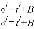
앞서 설명한 바와 같이 복수의 광원(102)에서 송출되는 가시광통신 신호의 시각이 서로 동기되어 있는 경우에는, i번, j번 광원(102a, 102b)에서 같은 가시광통신 신호를 동시에 송출하는 것이 가능하므로, 이 경우 단말기(200)는 복수의 광원(102) 중에서 i번, j번 광원(102a, 102b)을 통해 송출된 가시광통신 신호를 수신한 시간으로 수학식 1과 같이 모델링하여 측정치를 수집할 수 있다.As described above, when the times of the visible light signals transmitted from the plurality of

수학식 1에서, ti, tj는 도 2에 도시하는 바와 같이 i, j번째 광원(102a, 102b)으로부터 단말기(200)까지 신호가 도달하는 데 걸리는 시간이고, B는 단말기(200)의 시계 오차이다.In Equation 1, t i , t j are the time it takes for the signal to arrive from the i, j
이상에서 살펴본 바와 같이 본 발명의 실시예에서는 가시광통신 신호의 수신 시간을 측정치로 사용하는 방법을 예로 들어 설명하기로 한다. 그러나, 측정치는 가시광통신 장치(100)와 단말기(200)가 펄스 신호, 코드, 반송파, 부반송파를 포함하는 신호 군으로부터 어떤 신호를 선택하여 통신을 수행하느냐에 따라 달라질 수 있음을 밝힌다. 예를 들어, 반송파를 사용하는 경우 광원 간의 간격을 반송파의 반파장 미만의 거리 내에 배치함으로써, 반송파의 미지정수를 제거하고 난 후에 반송파 위상을 측정치로 사용하여, 광원(102)으로부터 단말기(200)까지의 거리에 대한 수학식으로 측정치를 모델링할 수 있다.As described above, in the embodiment of the present invention, a method of using a reception time of a visible light communication signal as a measurement will be described as an example. However, the measurement value reveals that the visible
여기서, 단말기(200)는 GSM(Global System for Mobile) 폰, W-CDMA(Wideband CDMA) 폰, CDMA-2000 폰, MBS(Mobile Broad and System) 폰, 스마트 폰, PDA(Personal Digi), 태블릿 PC 등과 같이 이동이 가능한 단말기나 PC 등과 같이 어느 한 장소에 고정설치된 단말기 등으로 구현될 수 있다.Here, the
한편, 위치 계산 모듈(300)은 단말기(200)에서 수집된 통신 채널별 측정치에 의거하여 단말기(200)의 위치를 계산한다. 이때, 위치 계산 모듈(300)은 단말기(200)에서 수집된 통신 채널별 측정치에 의거하여 각각의 광원(102)으로부터 단말기(200)까지의 거리의 채널간 차분값을 계산한 후, 계산된 각각의 광원(102)으로부터 단말기(200)까지의 거리의 채널간 차분값을 이용하여 단말기(200)의 위치를 계산할 수도 있다.On the other hand, the
전술한 바와 같이, 위치 계산 모듈(300)은 단말기(200)에서 수집된 통신 채널별 측정치에 의거하여 각각의 광원(102)으로부터 단말기(200)까지 거리의 채널간 차분값을 계산하는 데, 수학식 1을 통해 얻은 i번, j번 광원(102a, 102b)으로부터 수신한 가시광통신 신호에 대한 측정치를 i번째 광원(102a)과 j번째 광원(102b)에 대해 차분하면 수학식 2와 같은 결과를 얻을 수 있게 된다.As described above, the

수학식 2를 통해 알 수 있듯이, 차분을 통해 단말기(200)의 시계 오차가 제거되었으며, 차분된 측정치에 광속(C)을 곱하면 단말기(200)에서 얻은 측정치의 차분값으로부터 단말기(200)로부터 광원(102a, 102b)까지의 실제 거리의 차분값을 얻을 수 있다.As can be seen from Equation 2, the clock error of the
여기서, 수학식 2를 단말기(200)의 위치와 i번, j번 광원(102a, 102b)의 위치에 대해 다시 정리하면 수학식 3과 같다.Here, Equation 2 is rearranged with respect to the position of the

수학식 3에서, (xi, yi, zi)는 가시광통신 장치(100)의 i번째 광원(102a)의 위치이고, (xj, yj, zj)는 가시광통신 장치(100)의 j번째 광원(102b)의 위치이며, (x, y, z)는 단말기(200)의 실제 위치(2차원 위치해이므로, z는 알고 있는 값)이다.In Equation 3, (x i , y i , z i ) is the position of the i-
총 3개의 광원을 갖는 경우를 가정하면, 수학식 3과 같은 수학식을 하나 더 얻을 수 있으며, 미지수가 x, y로 2개이고, 측정식이 2개이므로, 이 방정식을 풀어 위치해인 x, y를 얻을 수 있게 된다.Assuming a total of three light sources, one more equation such as Equation 3 can be obtained, and two unknowns are x and y, and two measurement equations. You can get it.
마찬가지 방법으로 총 2개의 광원을 갖는 경우라면 1차원 위치(방위각), 4개 이상의 광원을 갖는 경우라면 3차원 위치(x, y, z)의 계산이 가능하다.In the same way, when there are two light sources in total, one-dimensional position (azimuth angle), and when there are four or more light sources, three-dimensional positions (x, y, z) can be calculated.
본 발명의 실시예에서는 3개의 광원으로부터 얻은 측정치를 사용하여 2차원 위치(x, y)를 계산하는 방법을 예로 들어 설명하기로 한다.In the embodiment of the present invention, a method of calculating the two-dimensional position (x, y) using the measurements obtained from three light sources will be described as an example.
전술한 수학식 3과 같은 방정식을 푸는 방법은 다양하나, 본 발명에서는 연립하고 근의 공식을 이용하는 방법을 사용한다.There are various methods of solving equations such as Equation 3 described above, but the present invention uses methods that use simultaneous and approximate formulas.
가시광통신 장치(100)의 복수의 광원(102)이 도 3에 도시하는 바와 같이 배치되어 있다고 할 때, 위치해는 수학식 4와 같이 나타낼 수 있다.When a plurality of

수학식 4에서, In Equation 4,

전술한 바와 같이, 얻어진 위치해 x, y를 이용하여 위치 계산 모듈(300)은 단말기(200)의 위치를 구할 수 있게 된다.As described above, the
이와 같이, 위치 계산 모듈(300)은 수학식 4를 통해 한 쌍의 해를 얻게 되는 데, 도출된 해를 원래의 식인 수학식 3에 대입했을 때, 참값이 아닌 경우, 해당 식을 만족하지 못하기 때문에, 원하는 해를 얻을 수 있다.As described above, the
전술한 바와 같이, 위치해 x, y를 구한 위치 계산 모듈(300)은 위치해 x, y와 가시광통신 장치(100)로부터 수신한 가시광통신 신호에 포함되어 있는 식별 정보에 매핑되어 있는 가시광통신 장치(100)의 위치 정보에 의거하여 단말기(200)의 현재 위치를 추정한다.As described above, the
전술한, 위치 계산 모듈(300)은 도 1에 도시하는 바와 같이, 단말기(200) 내에 포함되어 구현될 수도 있고, 단말기(200)와 별도로 구현되어 단말기(200)와 양방향 통신을 수행할 수도 있다.As described above, the
도 4는 본 발명의 일 실시예에 따른 복수의 광원을 포함하는 단일 가시광통신 장치 기반 위치 확인 방법을 설명하기 위한 처리도이다.FIG. 4 is a process diagram illustrating a single visible optical communication device based positioning method including a plurality of light sources according to an embodiment of the present invention.
우선, 복수의 광원(102)을 포함하여 이루어지는 가시광통신 장치(100)는 복수의 광원(102)을 통해 주기적으로 가시광통신 신호를 송출한다.First, the visible
여기서, 가시광통신 장치(100)는 복수의 광원(102)을 통해 통신 채널별로 구분이 가능하고, 시각이 서로 동기되어 있는 가시광통신 신호를 송출하는 것이 바람직하다.Here, the visible
또한, 가시광통신 장치(100)는 복수의 광원(102)을 통해 송출하는 가시광통신 신호에 자신의 식별 정보를 포함시켜 송출한다.In addition, the visible
전술한 바와 같이, 가시광통신 장치(100)가 복수의 광원(102)을 통해 송출하는 가시광통신 신호는 단말기(200)가 수신하게 되는 데(S10), 가시광통신 장치(100)가 송출하는 가시광통신 신호를 수신한 단말기(200)는 가시광통신 신호를 수신한 시간을 수학식 1과 같이 모델링하여 통신 채널별로 측정치를 수집한다(S12).As described above, the visible light communication signal transmitted by the visible
이후, 위치 계산 모듈(300)은 상기한 과정 S12를 통해 단말기(200)에서 각 통신 채널별로 수집한 측정치에 의거하여 각 채널에 해당하는 광원(102)에서 단말기(200)까지의 거리의 채널간 차분값을 계산한다(S14).Thereafter, the
상기한 과정 S14에서 위치 계산 모듈(300)은 수학식 1을 통해 수집한 통신 채널별 측정치를 서로 차분하여 수학식 2와 같은 결과를 얻을 수 있게 된다.In the process S14, the
수학식 2를 통해 단말기(200)에서 각 통신 채널별로 수집한 측정치를 서로 차분한 값으로부터 복수의 광원(102)에서 단말기(200)까지의 실제 거리의 차분 값을 얻을 수 있게 된다.Through Equation 2, it is possible to obtain the difference value of the actual distance from the plurality of
전술한 바와 같이, 수학식 2를 통해 복수의 광원(102)에서 단말기(200)까지의 실제 거리의 차분 값을 얻는 위치 계산 모듈(300)은 이를 단말기(200)의 위치와 각 광원(102)의 위치에 대해 다시 정리하여 수학식3과 같은 측정식을 얻는다.As described above, the
이후, 위치 계산 모듈(300)은 상기한 과정 S14를 통해 얻은 각각의 광원(102)에서 단말기(200)까지의 거리의 채널간 차분 값을 이용하여 단말기(200)의 위치해를 계산한다(S16).Thereafter, the
상기한 과정 S16에서 위치 계산 모듈(300)은 상기한 과정 S14를 통해 얻은 측정식을 풀어 위치해(3개의 광원을 이용하는 경우: x, y)를 얻는다.In the above step S16, the
이후에는 상기한 과정 S16을 통해 획득한 단말기(200)의 위치해와 가시광통신 장치(100)의 위치 정보에 의거하여 단말기(200)의 현재 위치를 추정한다(S18).Thereafter, the current position of the terminal 200 is estimated based on the location of the terminal 200 acquired through the process S16 and the position information of the visible light communication apparatus 100 (S18).
상기한 과정 S18에서 위치 계산 모듈(300)은 가시광통신 장치(100)로부터 수신한 가시광통신 신호에 포함되어 있는 식별 정보에 의거하여, 해당 식별 정보에 매핑되어 있는 가시광통신 장치(100)의 위치 정보를 확인한 후, 확인된 가시광통신 장치(100)의 위치 정보와 상기한 과정 S16에서 획득한 단말기(200)의 위치해를 이용하여 단말기(200)의 현재 위치를 추정한다.In step S18, the
이상에서 살펴본 바와 같이, 복수의 광원(102)을 포함하는 가시광통신 장치(100)가 복수의 광원(102)을 통해 통신 채널별로 구분이 가능하고, 시각이 서로 동기되어 있는 가시광통신 신호를 송출함에 따라, 본 발명은 도 1에 도시하는 바와 같이 일정한 공간에서 복수의 단말기(200)가 하나의 가시광통신 장치(100)로부터 가시광통신 신호가 수신되는 경우에도 단말기 자신의 위치를 확인하게 된다. 즉, 단 하나의 가시광통신 장치(100)를 이용하여 복수의 단말기(200)가 실내에서 비교적 정확한 위치를 계산할 수 있게 된다.As described above, the visible
이상 본 발명의 특정 실시예를 도시하고 설명하였으나, 본 발명의 기술사상은 첨부된 도면과 상기한 설명내용에 한정하지 않으며 본 발명의 사상을 벗어나지 않는 범위 내에서 다양한 형태의 변형이 가능함은 이 분야의 통상의 지식을 가진 자에게는 자명한 사실이며, 이러한 형태의 변형은, 본 발명의 정신에 위배되지 않는 범위 내에서 본 발명의 특허청구범위에 속한다고 볼 것이다.While the present invention has been particularly shown and described with reference to exemplary embodiments thereof, it is clearly understood that the same is by way of illustration and example only and is not to be taken as limitations. It will be understood by those skilled in the art that various changes in form and details may be made therein without departing from the spirit and scope of the invention as defined by the appended claims.
100. 가시광통신 장치, 102. 광원,
102a. 가시광통신 장치가 포함하는 광원들 중에서 임의로 선택된 i번 광원,
102b. 가시광통신 장치가 포함하는 광원들 중에서 임의로 선택된 j번 광원,
200. 단말기, 300. 위치 계산 모듈100. visible light communication device, 102. light source,
102a. Light source i randomly selected from light sources included in the visible light communication device,
102b. Light source j randomly selected from light sources included in the visible light communication device;
200. Terminal, 300. Position calculation module
Claims (11)
상기 복수의 광원을 통해 송출하는 가시광통신 신호를 수신하고, 수신한 각각의 가시광통신 신호로부터 통신 채널별 측정치를 수집하는 단말기와;
상기 수집된 통신 채널별 측정치에 의거하여 상기 단말기의 위치를 계산하는 위치 계산 모듈을 포함하여 이루어지는 복수의 광원을 포함하는 단일 가시광통신 장치 기반 위치 확인 시스템.
A visible light communication device including a plurality of light sources and transmitting a visible light communication signal through the plurality of light sources;
A terminal for receiving a visible light communication signal transmitted through the plurality of light sources and collecting measurements for each communication channel from the received visible light communication signals;
A single visible light communication device based positioning system comprising a plurality of light sources comprising a position calculation module for calculating the position of the terminal based on the collected measurement for each communication channel.
통신 채널별로 구분 가능한 신호인 것을 특징으로 하는 복수의 광원을 포함하는 단일 가시광통신 장치 기반 위치 확인 시스템.
The method of claim 1, wherein each visible light communication signal transmitted through the plurality of light sources,
A single visible optical communication device based positioning system comprising a plurality of light sources, characterized in that the signal is distinguishable for each communication channel.

여기서, ti, tj는 i, j번째 광원으로부터 단말기까지 신호가 도달하는 데 걸리는 시간,
B는 단말기의 시계 오차인 것을 특징으로 하는 복수의 광원을 포함하는 단일 가시광통신 장치 기반 위치 확인 시스템.
The method of claim 1, wherein the measurement for each communication channel is
Here, t i , t j is the time it takes for the signal to reach the terminal from the i, j light source,
B is a single visible light communication device based positioning system comprising a plurality of light sources, characterized in that the clock error of the terminal.
상기 수집된 통신 채널별 측정치에 의거하여 각각의 광원으로부터 단말기까지 거리의 채널간 차분값을 계산한 후, 계산된 각각의 광원으로부터 단말기까지 거리의 채널간 차분값을 이용하여 상기 단말기의 위치를 계산하는 것을 특징으로 하는 복수의 광원을 포함하는 단일 가시광통신 장치 기반 위치 확인 시스템.
The method of claim 1, wherein the position calculation module,
After calculating the channel-to-channel difference value of the distance from each light source to the terminal based on the collected communication channel-specific measurements, the position of the terminal is calculated using the calculated channel-to-channel difference value of the distance from each light source to the terminal. A single visible light communication device based positioning system comprising a plurality of light sources, characterized in that.

여기서, (xi, yi, zi)는 가시광통신 장치의 i번째 광원의 위치,
(xj, yj, zj)는 가시광통신 장치의 j번째 광원의 위치,
(x, y, z)는 단말기의 실제 위치인 것을 특징으로 하는 복수의 광원을 포함하는 단일 가시광통신 장치 기반 위치 확인 시스템.
The method of claim 4, wherein the channel-to-channel difference value of the distance from each light source to the terminal,
Here, (x i , y i , z i ) is the position of the i-th light source of the visible light communication device,
(x j , y j , z j ) is the position of the j th light source of the visible light communication device,
(x, y, z) is a single visible light communication device based positioning system comprising a plurality of light sources, characterized in that the actual location of the terminal.

여기서,

The method of claim 1, wherein the location of the terminal,
here,
상기 가시광통신 신호를 수신한 단말기에서 상기 가시광통신 신호를 수신한 시간을 모델링하여 통신 채널별로 측정치를 수집하는 과정과;
상기 통신 채널별로 수집한 측정치를 이용하여 상기 단말기의 현재 위치를 추정하는 단말기 현재 위치 추정 과정을 포함하여 이루어지는 복수의 광원을 포함하는 단일 가시광통신 장치 기반 위치 확인 방법.
Transmitting a visible light communication signal through the plurality of light sources in a visible light communication device including a plurality of light sources;
Modeling a time at which the visible light communication signal is received by the terminal receiving the visible light communication signal and collecting a measurement value for each communication channel;
And a terminal current position estimating step of estimating a current position of the terminal using the measurements collected for each communication channel.
여기서, ti, tj는 i, j번째 광원으로부터 단말기까지 신호가 도달하는 데 걸리는 시간,
B는 단말기의 시계 오차인 것을 특징으로 하는 복수의 광원을 포함하는 단일 가시광통신 장치 기반 위치 확인 방법.
The method of claim 7, wherein the measurement collected for each communication channel,
Here, t i , t j is the time it takes for the signal to reach the terminal from the i, j light source,
B is a single visible light communication device based positioning method comprising a plurality of light sources, characterized in that the clock error of the terminal.
상기 통신 채널별로 수집한 측정치를 이용하여 각각의 광원에서 단말기까지의 거리의 채널간 차분값을 계산하는 과정과;
상기 각각의 광원에서 단말기까지의 거리의 채널간 차분값을 이용하여 단말기의 위치해를 계산하는 과정과;
상기 단말기의 위치해와 상기 가시광통신 장치의 위치 정보를 이용하여 상기 단말기의 현재 위치를 추정하는 과정을 포함하여 이루어지는 것을 특징으로 하는 복수의 광원을 포함하는 단일 가시광통신 장치 기반 위치 확인 방법.
The method of claim 7, wherein the terminal current position estimation process,
Calculating a channel-to-channel difference value of the distance from each light source to the terminal using the measurements collected for each communication channel;
Calculating the position of the terminal by using the channel-to-channel difference value of the distance from each light source to the terminal;
And estimating a current position of the terminal using the location of the terminal and the position information of the visible light communication device.

여기서, (xi, yi, zi)는 가시광통신 장치의 i번째 광원의 위치,
(xj, yj, zj)는 가시광통신 장치의 j번째 광원의 위치,
(x, y, z)는 단말기의 실제 위치인 것을 특징으로 하는 복수의 광원을 포함하는 단일 가시광통신 장치 기반 위치 확인 방법.
The method of claim 9, wherein the channel-to-channel difference value of the distance from each light source to the terminal,
Here, (x i , y i , z i ) is the position of the i-th light source of the visible light communication device,
(x j , y j , z j ) is the position of the j th light source of the visible light communication device,
(x, y, z) is a single visible light communication device based positioning method comprising a plurality of light sources, characterized in that the actual location of the terminal.

여기서,

here,
Priority Applications (1)
| Application Number | Priority Date | Filing Date | Title |
|---|---|---|---|
| KR1020100092476A KR101175872B1 (en) | 2010-09-20 | 2010-09-20 | Positioning system and method based on single visible light communication apparatus comprising multiple light sources |
Applications Claiming Priority (1)
| Application Number | Priority Date | Filing Date | Title |
|---|---|---|---|
| KR1020100092476A KR101175872B1 (en) | 2010-09-20 | 2010-09-20 | Positioning system and method based on single visible light communication apparatus comprising multiple light sources |
Publications (2)
| Publication Number | Publication Date |
|---|---|
| KR20120030756A KR20120030756A (en) | 2012-03-29 |
| KR101175872B1 true KR101175872B1 (en) | 2012-08-21 |
Family
ID=46134609
Family Applications (1)
| Application Number | Title | Priority Date | Filing Date |
|---|---|---|---|
| KR1020100092476A Active KR101175872B1 (en) | 2010-09-20 | 2010-09-20 | Positioning system and method based on single visible light communication apparatus comprising multiple light sources |
Country Status (1)
| Country | Link |
|---|---|
| KR (1) | KR101175872B1 (en) |
Cited By (1)
| Publication number | Priority date | Publication date | Assignee | Title |
|---|---|---|---|---|
| KR102395559B1 (en) | 2020-12-18 | 2022-05-10 | 현대엘리베이터주식회사 | Visible light communication elevator system using hoistway lighting |
Families Citing this family (3)
| Publication number | Priority date | Publication date | Assignee | Title |
|---|---|---|---|---|
| KR101630402B1 (en) * | 2014-05-23 | 2016-06-27 | 에스케이 텔레콤주식회사 | Method and Apparatus for Positioning Terminal Using Information on Contrast and Color |
| CN106537963B (en) * | 2014-06-13 | 2021-04-27 | 飞利浦灯具控股公司 | Location based on wireless node network |
| KR101997532B1 (en) | 2017-11-06 | 2019-07-09 | 한국과학기술원 | Apparatus and method for searching position of terminal in wireless optical communication system |
Citations (3)
| Publication number | Priority date | Publication date | Assignee | Title |
|---|---|---|---|---|
| JP2003515153A (en) | 1999-11-26 | 2003-04-22 | ドクトル・ヨハネス・ハイデンハイン・ゲゼルシヤフト・ミツト・ベシユレンクテル・ハフツング | Angle measurement system |
| JP2005236667A (en) | 2004-02-19 | 2005-09-02 | Nippon Telegr & Teleph Corp <Ntt> | Communications system |
| JP2006505784A (en) | 2002-11-11 | 2006-02-16 | キネティック リミテッド | Ranging device |
-
2010
- 2010-09-20 KR KR1020100092476A patent/KR101175872B1/en active Active
Patent Citations (3)
| Publication number | Priority date | Publication date | Assignee | Title |
|---|---|---|---|---|
| JP2003515153A (en) | 1999-11-26 | 2003-04-22 | ドクトル・ヨハネス・ハイデンハイン・ゲゼルシヤフト・ミツト・ベシユレンクテル・ハフツング | Angle measurement system |
| JP2006505784A (en) | 2002-11-11 | 2006-02-16 | キネティック リミテッド | Ranging device |
| JP2005236667A (en) | 2004-02-19 | 2005-09-02 | Nippon Telegr & Teleph Corp <Ntt> | Communications system |
Cited By (1)
| Publication number | Priority date | Publication date | Assignee | Title |
|---|---|---|---|---|
| KR102395559B1 (en) | 2020-12-18 | 2022-05-10 | 현대엘리베이터주식회사 | Visible light communication elevator system using hoistway lighting |
Also Published As
| Publication number | Publication date |
|---|---|
| KR20120030756A (en) | 2012-03-29 |
Similar Documents
| Publication | Publication Date | Title |
|---|---|---|
| KR102253830B1 (en) | Positioning system | |
| EP3425813B1 (en) | Pulse shaping interoperability protocol for ultra wideband systems | |
| EP2149227B1 (en) | Method for measuring location of radio frequency identification reader by using beacon | |
| KR102198492B1 (en) | Positioning system | |
| CN104135305B (en) | Ranging and alignment system | |
| US20070041352A1 (en) | Elevator calling mechanism and method | |
| US11102746B2 (en) | Positioning system | |
| KR101430247B1 (en) | Method for measuring 3 Dimensional location using visible light communication indoor and system thereof, and method for providing location based service | |
| US9568584B2 (en) | Wireless positioning server using clock offset calibration positioning method using the same | |
| Savić et al. | Constrained localization: A survey | |
| KR20110061767A (en) | Real time location system and method for making a location information based on finger printing | |
| KR101814698B1 (en) | Method for simultaneously setting coordinates of anchor and tag using wireless transmission / reception and communication system thereof | |
| US20210172736A1 (en) | Supporting a determination of floor heights | |
| KR20130136708A (en) | Apparatus and method for estimating location | |
| KR101175872B1 (en) | Positioning system and method based on single visible light communication apparatus comprising multiple light sources | |
| KR20100128409A (en) | Location based service relay system | |
| CN203416427U (en) | Ad hoc network positioning system based on ZigBee technology | |
| KR101342215B1 (en) | Method and system for determining position based on radio frequency identification | |
| JP2011133331A (en) | Positioning system and positioning method | |
| Liu et al. | A novel indoor localization system based on passive RFID technology | |
| Moschevikin et al. | The impact of nlos components in time-of-flight networks for indoor positioning systems | |
| Sang | Bidirectional UWB localization with rigorous sectoral evaluations | |
| Angelis et al. | Experimental radio indoor positioning systems based on round-trip time measurement | |
| Liu et al. | Assessment of indoor positioning system using Kriging fingerprinting method and IEEE 802.11 v standard | |
| JP2004108903A5 (en) |
Legal Events
| Date | Code | Title | Description |
|---|---|---|---|
| PA0109 | Patent application |
St.27 status event code: A-0-1-A10-A12-nap-PA0109 |
|
| A201 | Request for examination | ||
| P11-X000 | Amendment of application requested |
St.27 status event code: A-2-2-P10-P11-nap-X000 |
|
| P13-X000 | Application amended |
St.27 status event code: A-2-2-P10-P13-nap-X000 |
|
| PA0201 | Request for examination |
St.27 status event code: A-1-2-D10-D11-exm-PA0201 |
|
| PN2301 | Change of applicant |
St.27 status event code: A-3-3-R10-R13-asn-PN2301 St.27 status event code: A-3-3-R10-R11-asn-PN2301 |
|
| PE0902 | Notice of grounds for rejection |
St.27 status event code: A-1-2-D10-D21-exm-PE0902 |
|
| P11-X000 | Amendment of application requested |
St.27 status event code: A-2-2-P10-P11-nap-X000 |
|
| P13-X000 | Application amended |
St.27 status event code: A-2-2-P10-P13-nap-X000 |
|
| PG1501 | Laying open of application |
St.27 status event code: A-1-1-Q10-Q12-nap-PG1501 |
|
| E701 | Decision to grant or registration of patent right | ||
| PE0701 | Decision of registration |
St.27 status event code: A-1-2-D10-D22-exm-PE0701 |
|
| GRNT | Written decision to grant | ||
| PR0701 | Registration of establishment |
St.27 status event code: A-2-4-F10-F11-exm-PR0701 |
|
| PR1002 | Payment of registration fee |
St.27 status event code: A-2-2-U10-U11-oth-PR1002 Fee payment year number: 1 |
|
| PG1601 | Publication of registration |
St.27 status event code: A-4-4-Q10-Q13-nap-PG1601 |
|
| R18-X000 | Changes to party contact information recorded |
St.27 status event code: A-5-5-R10-R18-oth-X000 |
|
| PN2301 | Change of applicant |
St.27 status event code: A-5-5-R10-R13-asn-PN2301 St.27 status event code: A-5-5-R10-R11-asn-PN2301 |
|
| PN2301 | Change of applicant |
St.27 status event code: A-5-5-R10-R13-asn-PN2301 St.27 status event code: A-5-5-R10-R11-asn-PN2301 |
|
| FPAY | Annual fee payment |
Payment date: 20150730 Year of fee payment: 4 |
|
| PR1001 | Payment of annual fee |
St.27 status event code: A-4-4-U10-U11-oth-PR1001 Fee payment year number: 4 |
|
| FPAY | Annual fee payment |
Payment date: 20160212 Year of fee payment: 5 |
|
| PR1001 | Payment of annual fee |
St.27 status event code: A-4-4-U10-U11-oth-PR1001 Fee payment year number: 5 |
|
| P22-X000 | Classification modified |
St.27 status event code: A-4-4-P10-P22-nap-X000 |
|
| FPAY | Annual fee payment |
Payment date: 20170724 Year of fee payment: 6 |
|
| PR1001 | Payment of annual fee |
St.27 status event code: A-4-4-U10-U11-oth-PR1001 Fee payment year number: 6 |
|
| PR1001 | Payment of annual fee |
St.27 status event code: A-4-4-U10-U11-oth-PR1001 Fee payment year number: 7 |
|
| R18-X000 | Changes to party contact information recorded |
St.27 status event code: A-5-5-R10-R18-oth-X000 |
|
| R18-X000 | Changes to party contact information recorded |
St.27 status event code: A-5-5-R10-R18-oth-X000 |
|
| PN2301 | Change of applicant |
St.27 status event code: A-5-5-R10-R11-asn-PN2301 |
|
| PN2301 | Change of applicant |
St.27 status event code: A-5-5-R10-R14-asn-PN2301 |
|
| P14-X000 | Amendment of ip right document requested |
St.27 status event code: A-5-5-P10-P14-nap-X000 |
|
| P16-X000 | Ip right document amended |
St.27 status event code: A-5-5-P10-P16-nap-X000 |
|
| PN2301 | Change of applicant |
St.27 status event code: A-5-5-R10-R13-asn-PN2301 St.27 status event code: A-5-5-R10-R11-asn-PN2301 |
|
| Q16-X000 | A copy of ip right certificate issued |
St.27 status event code: A-4-4-Q10-Q16-nap-X000 |
|
| FPAY | Annual fee payment |
Payment date: 20190809 Year of fee payment: 8 |
|
| PR1001 | Payment of annual fee |
St.27 status event code: A-4-4-U10-U11-oth-PR1001 Fee payment year number: 8 |
|
| PR1001 | Payment of annual fee |
St.27 status event code: A-4-4-U10-U11-oth-PR1001 Fee payment year number: 9 |
|
| PN2301 | Change of applicant |
St.27 status event code: A-5-5-R10-R13-asn-PN2301 St.27 status event code: A-5-5-R10-R11-asn-PN2301 |
|
| PR1001 | Payment of annual fee |
St.27 status event code: A-4-4-U10-U11-oth-PR1001 Fee payment year number: 10 |
|
| R18-X000 | Changes to party contact information recorded |
St.27 status event code: A-5-5-R10-R18-oth-X000 |
|
| R18-X000 | Changes to party contact information recorded |
St.27 status event code: A-5-5-R10-R18-oth-X000 |
|
| PR1001 | Payment of annual fee |
St.27 status event code: A-4-4-U10-U11-oth-PR1001 Fee payment year number: 11 |
|
| R18-X000 | Changes to party contact information recorded |
St.27 status event code: A-5-5-R10-R18-oth-X000 |
|
| R18-X000 | Changes to party contact information recorded |
St.27 status event code: A-5-5-R10-R18-oth-X000 |
|
| PR1001 | Payment of annual fee |
St.27 status event code: A-4-4-U10-U11-oth-PR1001 Fee payment year number: 12 |
|
| PR1001 | Payment of annual fee |
St.27 status event code: A-4-4-U10-U11-oth-PR1001 Fee payment year number: 13 |
|
| R18-X000 | Changes to party contact information recorded |
St.27 status event code: A-5-5-R10-R18-oth-X000 |
|
| R18-X000 | Changes to party contact information recorded |
St.27 status event code: A-5-5-R10-R18-oth-X000 |
|
| R18 | Changes to party contact information recorded |
Free format text: ST27 STATUS EVENT CODE: A-5-5-R10-R18-OTH-X000 (AS PROVIDED BY THE NATIONAL OFFICE) |
|
| R18-X000 | Changes to party contact information recorded |
St.27 status event code: A-5-5-R10-R18-oth-X000 |