KR101174910B1 - Rotor position detection in an electrical machine - Google Patents
Rotor position detection in an electrical machine Download PDFInfo
- Publication number
- KR101174910B1 KR101174910B1 KR1020050049551A KR20050049551A KR101174910B1 KR 101174910 B1 KR101174910 B1 KR 101174910B1 KR 1020050049551 A KR1020050049551 A KR 1020050049551A KR 20050049551 A KR20050049551 A KR 20050049551A KR 101174910 B1 KR101174910 B1 KR 101174910B1
- Authority
- KR
- South Korea
- Prior art keywords
- signal
- error
- switched reluctance
- rotor position
- position transducer
- Prior art date
- Legal status (The legal status is an assumption and is not a legal conclusion. Google has not performed a legal analysis and makes no representation as to the accuracy of the status listed.)
- Expired - Fee Related
Links
Images


Classifications
-
- H—ELECTRICITY
- H02—GENERATION; CONVERSION OR DISTRIBUTION OF ELECTRIC POWER
- H02P—CONTROL OR REGULATION OF ELECTRIC MOTORS, ELECTRIC GENERATORS OR DYNAMO-ELECTRIC CONVERTERS; CONTROLLING TRANSFORMERS, REACTORS OR CHOKE COILS
- H02P6/00—Arrangements for controlling synchronous motors or other dynamo-electric motors using electronic commutation dependent on the rotor position; Electronic commutators therefor
- H02P6/14—Electronic commutators
- H02P6/16—Circuit arrangements for detecting position
- H02P6/18—Circuit arrangements for detecting position without separate position detecting elements
-
- H—ELECTRICITY
- H02—GENERATION; CONVERSION OR DISTRIBUTION OF ELECTRIC POWER
- H02P—CONTROL OR REGULATION OF ELECTRIC MOTORS, ELECTRIC GENERATORS OR DYNAMO-ELECTRIC CONVERTERS; CONTROLLING TRANSFORMERS, REACTORS OR CHOKE COILS
- H02P25/00—Arrangements or methods for the control of AC motors characterised by the kind of AC motor or by structural details
- H02P25/02—Arrangements or methods for the control of AC motors characterised by the kind of AC motor or by structural details characterised by the kind of motor
- H02P25/08—Reluctance motors
- H02P25/086—Commutation
- H02P25/089—Sensorless control
-
- H—ELECTRICITY
- H02—GENERATION; CONVERSION OR DISTRIBUTION OF ELECTRIC POWER
- H02P—CONTROL OR REGULATION OF ELECTRIC MOTORS, ELECTRIC GENERATORS OR DYNAMO-ELECTRIC CONVERTERS; CONTROLLING TRANSFORMERS, REACTORS OR CHOKE COILS
- H02P6/00—Arrangements for controlling synchronous motors or other dynamo-electric motors using electronic commutation dependent on the rotor position; Electronic commutators therefor
- H02P6/14—Electronic commutators
- H02P6/16—Circuit arrangements for detecting position
Landscapes
- Engineering & Computer Science (AREA)
- Power Engineering (AREA)
- Control Of Electric Motors In General (AREA)
- Control Of Motors That Do Not Use Commutators (AREA)
Abstract
전기 기기는 제어 시스템에 출력신호를 제공하는 로터 위치 변환기를 가진다. 상기 출력신호는 구성 요소의 결함 및 제조 결함에 기인하는 에러를 포함한다. 본 발명은 기기의 제어 시스템에 보상치를 제공하기 위하여 위치 검출 알고리즘을 사용함으로써 신호의 에러를 검출하고 할 수 있는 방법을 개시한다. 보상치는 제어 시스템에 저장될 수 있으며 변환기의 출력신호의 정확도를 개선하는데 사용될 수 있으므로, 기기의 출력을 개선할 수 있게 된다.The electrical appliance has a rotor position transducer which provides an output signal to the control system. The output signal includes errors due to component defects and manufacturing defects. The present invention discloses a method that can detect and make errors in a signal by using a position detection algorithm to provide compensation to the control system of the device. The compensation value can be stored in the control system and used to improve the accuracy of the output signal of the transducer, thereby improving the output of the device.
Description
도 1은 통상의 종래 기술에 따른 스위치드 릴럭턴스 드라이브에 대한 도면,1 is a diagram of a switched reluctance drive according to a conventional prior art;
도 2는 도 1에 도시된 컨버터의 공지된 단일 위상 토폴로지에 대한 도면,2 is a diagram of a known single phase topology of the converter shown in FIG.
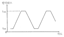
도 3a는 로터 각도 함수로서의 스위치드 릴럭턴스 기기의 인덕턴스 프로파일에 대한 도면,3A is a diagram of an inductance profile of a switched reluctance device as a function of rotor angle,
도 3b는 위상 A에 대해 로터가 완전 정렬된 위치(Lmax)에 있는 스위치드 릴럭턴스 기기의 개략도.3B is a schematic diagram of a switched reluctance device with the rotor in full alignment L max with respect to phase A;
도 3c는 위상 A에 대해 로터가 완전 비정렬된 위치(Lmin)에 있는 스위치드 릴럭턴스 기기의 개략도.3C is a schematic diagram of a switched reluctance machine with the rotor in full misalignment position L min with respect to phase A;
도 4는 3상 시스템용의 로터 위치 변환기의 소자들을 도시한 도면.4 shows the elements of a rotor position transducer for a three phase system.
도 5는 도 4의 변환기에 대한 인덕턴스 프로파일과 센서 신호간의 상호관계를 도시한 도면.FIG. 5 illustrates the interrelation between inductance profile and sensor signal for the transducer of FIG. 4. FIG.
도 6은 본 발명의 하나의 실시예에 따른 장치를 도시한 도면.6 illustrates an apparatus according to one embodiment of the present invention.
본 발명은 전기 기기, 특히 이에 한정되지는 않지만 스위치드 릴럭턴스 기기의 로터 위치 검출기에서의 에러 보상에 관한 것이다.The present invention relates to error compensation in a rotor position detector of an electrical device, in particular but not limited to switched reluctance device.
스위치드 릴럭턴스 시스템의 특성 및 동작은 종래 기술에 잘 알려져 있으며, 예를 들면, 1993년 6월 21일 ~ 24일 독일 뉘른베르그(Nurnberg)에서 개최된 PCIM'93에서 발표된 스티븐슨(Stephenson)과 블레이크(Blake)의 논문 "스위치드 릴럭턴스 모터 및 드라이브의 특성, 설계 및 응용(The characteristics, design and application of switched reluctance motors and drives)"에 기술되어 있고, 이 논문은 본 명세서에 인용되어 있다. 드라이브의 일반적인 취급은 여러 책자에서 발견할 수 있는데, 예컨대 TJE Miller, Newnes 2001에 의한 스위치드 릴럭턴스 머신의 전자 제어("Electronic Control of Switched Reluctance Machines") 등이 있다. 도 1은 통상의 스위치드 릴럭턴스 드라이브를 개략적인 형태로 도시하고 있는데, 여기서 스위치드 릴럭턴스 모터(12)는 부하(19)를 구동한다. 입력 DC 전원 공급부(11)는 배터리이거나 정류되고 필터링된 AC 주전원일 수 있다. 전원 공급부(11)에 의해 공급되는 DC 전압은 전자 제어 유닛(14)의 제어를 받는 전력 컨버터(13)에 의해 모터(12)의 위상 권선(16) 양단에서 스위칭된다. The characteristics and operation of switched reluctance systems are well known in the art, for example, Stephenson and Blake, presented at PCIM'93 held in Nurnberg, Germany, June 21-24, 1993. (Blake's article "The characteristics, design and application of switched reluctance motors and drives"), which is hereby incorporated by reference. The general handling of the drive can be found in several books, such as "Electronic Control of Switched Reluctance Machines" by TJE Miller, Newnes 2001. 1 shows in schematic form a conventional switched reluctance drive, where the switched
스위칭은 드라이브의 적절한 동작을 위해 로터의 회전각에 정확하게 동기되어야만 하고, 로터 위치 변환기(rotor position transducer: 'rpt')(15)는 통상적으로 로터의 각도 위치에 대응되는 신호를 공급하는 데 이용된다. 로터 위치 변환기(15)는 기기의 위상 주기당 2 개의 전이를 가진 이진 신호를 출력하는 디바이스 이고, 기기의 전기적인 사이클에 주기적이다. 전이는 기기의 전기적인 사이클에서의 이벤트의 출현을 나타내는 것으로서, 예컨대 이벤트로는 최고 및 최소 인덕턴스의 출현 또는 이들 이벤트에 근접한 위치 등이 있고, 이 이벤트에 관련되어 제어 동작이 발생되게 된다. 이들 디바이스는 높은 위치 정확도를 요구하는 서보 시스템에서 통상적으로 채용되는 더 정확한 엔코더(encoder) 또는 리졸버(resolver)에 비교하여 비교적 저렴하다.Switching must be accurately synchronized to the rotational angle of the rotor for proper operation of the drive, and a rotor position transducer (rpt ') 15 is typically used to supply a signal corresponding to the angular position of the rotor. . The
많은 상이한 전력 컨버터 토폴로지가 공지되어 있으며, 이 중 여러 개의 토폴로지가 상기에서 인용한 스티븐슨 논문에서 다루어지고 있다. 도 2는 다상 시스템의 단일 위상에 대한 가장 통상적인 구성 중의 하나를 도시하고 있다. 도 2를 참조하면, 기기의 위상 권선(16)은 버스바(26, 27)를 가로질러 2 개의 스위칭 소자(21, 22)와 직렬로 연결되어 있다. 이하에서는, 버스바(26, 27)는 전력 컨버터의 "DC 링크"로서 통칭된다. 에너지 귀환 다이오드(23, 24)는 스위칭 소자(21, 22)가 개방될 때 권선 전류가 DC 링크로 환류되도록 권선에 연결되어 있다. 저항(28)은 전류 피드백 신호를 공급하기 위해 하부 스위칭 소자(22)와 직렬로 연결되어 있다. "DC 링크 커패시터"로서 공지된 커패시터(25)는 입력 DC 전원 공급부(11)로부터 유도되거나 또는 입력 DC 전원 공급부(11)로 복귀될 수 없는 DC 링크 전류의 임의의 교류 성분(즉, "리플 전류")을 제공하거나 또는 감소시키기 위해 DC 링크를 가로질러 연결된다. 실제로, 상기 커패시터(25)는 직렬 및/또는 병렬로 연결된 복수의 커패시터를 포함할 수 있다. 여기서, 병렬 연결이 사용되는 경우, 몇몇 소자들은 전력 컨버터의 도처에 분포될 수 있다. 통상적으로 다위상 시스템은 전기 기기의 위 상을 여기(energise)시키기 위해 병렬 연결된 도 2와 같은 복수의 "위상 레그(phase legs)"를 사용한다. 전류 측정 저항 대신에, 격리형 및/또는 불침투형 전류 검출기(isolated and/or non-invasive current detector)가 사용될 수 있다.Many different power converter topologies are known, several of which are discussed in the Stevenson paper cited above. 2 illustrates one of the most common configurations for a single phase of a multiphase system. Referring to FIG. 2, the
스위치드 릴럭턴스 기기의 위상 인덕턴스 사이클은 위상에 대한(또는, 각각의 위상에 대한), 예컨대 로터 폴(poles) 및 연관된 각각의 스테이터 폴이 완전 정렬되어 있을 때의 최고치 간의 인덕턴스 변화량과 같은 인덕턴스 변화량의 주기이다. 위상에 대한 이상적인 형태의 인덕턴스 곡선이 도 3a에 도시되어 있다. 실제에 있어서, Lmin 및 Lmax에서의 예각부분은 플럭스 프린지(flux fringe) 및 자기회로의 포화에 기인하여 라운드된다. 또한, 인덕턴스의 최고치는 전류에 의존하게 된다. 그럼에도 불구하고, 이 곡선은 기기의 일반적인 동작 행태를 기술하는 데 유용하다. 상기에서 인용된 스티븐슨의 논문에 상세히 설명되어 있는 바와 같이, 최대 인덕턴스 영역 Lmax는 로터 폴들의 쌍이 스테이터 폴들의 쌍과 완전히 정렬되는 지점에서의 로터 위치 주위에 집중된다. 이것은 도 3b의 3상, 6폴 스테이터, 4 폴 로터 기기에 대해서 나타내어진 바와 같다. 유사하게, 최소 인덕턴스 영역 Lmin은 도 3c에 도시된 바와 같이 로터 상의 인터폴라 축(interpolar axis)이 스테이터 폴 축과 정렬되는 위치에 해당된다.The phase inductance cycle of a switched reluctance device is based on the amount of change in inductance, such as the change in inductance for phase (or for each phase), for example between the rotor poles and the peak when each associated stator pole is fully aligned. It is a cycle. An ideal form of inductance curve for phase is shown in FIG. 3A. In practice, the sharp corners at L min and L max are rounded due to flux fringe and saturation of the magnetic circuit. Also, the peak of inductance will depend on the current. Nevertheless, this curve is useful for describing the general operating behavior of the device. As detailed in Stevenson's paper cited above, the maximum inductance area L max is concentrated around the rotor position at the point where the pair of rotor poles is completely aligned with the pair of stator poles. This is as shown for the three phase, six pole stator, four pole rotor machine of FIG. 3B. Similarly, the minimum inductance region L min corresponds to the position at which the interpolar axis on the rotor is aligned with the stator pole axis, as shown in FIG. 3C.
스위치드 릴럭턴스 기기의 성능은 로터 위치에 대한 위상 여기의 정확한 타이밍에 일부 의존한다. 로터 위치 검출은 스테이터 상에 장착되는 광학 또는 마그네틱 센서와 상호 협력하여 동작하는 것으로 기기의 로터 상에 장착되는 회전 치형 디스크(rotating toothed disc) 등의 도 1에 개략적으로 도시된 바와 같은 로터 위치 변환기(15)를 사용하여 통상적으로 달성된다. 스테이터에 대한 로터 위치를 나타내는 펄스열이 생성되고 제어 회로에 공급되어 정확한 위상 여기를 하도록 한다. 통상적으로, 단상 시스템 및 2상 시스템용으로는 하나의 센서가 사용되고, 3상 시스템용으로는 3개의 센서가 사용되며, 4상 시스템용으로는 4개 또는 2개의 센서가 사용된다. 단지 하나의 센서만을 사용하는 단순한 구조가 3상 또는 그 이상의 위상 시스템에서 가끔 사용된다. 이러한 위치 변환기는 소위 리졸버 또는 엔코더에 비해 훨씬 낮은 분해능을 제공하지만, 상당히 비용이 저렴하다. 정확도가 매우 높은 센서를 사용하는 것이 가능하지만, 이 비용은 특히 소형의 저비용 드라이브와 같은 드라이브의 전체 비용에 심각한 영향을 끼치게 될 것이다. The performance of switched reluctance devices depends in part on the exact timing of the phase excitation with respect to the rotor position. Rotor position detection operates in co-operation with an optical or magnetic sensor mounted on the stator, such as a rotor position transducer as shown schematically in FIG. 1, such as a rotating toothed disc mounted on the rotor of the instrument. Is typically achieved using 15). A pulse train representing the rotor position relative to the stator is generated and fed to the control circuit to ensure accurate phase excitation. Typically, one sensor is used for single phase systems and two phase systems, three sensors are used for three phase systems, and four or two sensors are used for four phase systems. Simple structures using only one sensor are sometimes used in three-phase or higher phase systems. These position transducers offer much lower resolution than so-called resolvers or encoders, but are quite inexpensive. Although it is possible to use a very accurate sensor, this cost will have a significant impact on the overall cost of the drive, especially for small, low cost drives.
도 4는 3상 시스템용의 이러한 로터 위치 변환기의 기본적인 구성 요소에 대한 개략도이다. 날개판(40)은 다수개의 캐스털레이션(castellation)을 가지고 있는데, 이 캐스털레이션은 로터 폴의 개수와 같고 3개 센서의 출력단에 동등한 마크:스페이스 비율(mark:space ratio)을 제공하기 위해서 등간격으로 배치된다. 센서는 위상의 인덕턴스 프로파일의 변위각에 대응하는 각도로 날개판 주위에 배치되고, 통상적으로 Lmin 및 Lmax 각각에 대해 라이징 엣지 및 폴링 엣지를 제공하도록 스테이터 폴에 대응하여 설정된다. 이는 센서로부터 발생되는 신호가 도 5에 도시된 바와 같은 위상의 인덕턴스 프로파일과의 상호관계를 가지는 결과를 가져온다. 전술한 바와 같이, 로터 위치 변환기(15)는 기기의 위상당 2 개의 전이를 가진 이진 신호 를 출력하는 디바이스이고, 기기의 전기적인 사이클에 주기적이다. 전이는 기기의 전기적인 사이클에서의 이벤트의 출현을 나타내는 것으로서, 예컨대 이벤트로는 최고 및 최소 인덕턴스의 출현 또는 이들 이벤트에 근접한 위치 등이 있고, 이 이벤트에 관련되어 제어 동작이 발생되게 된다. 이들 신호는 통상적으로 기기의 권선의 여기를 위해 정확한 인스턴트를 발생하도록 제어 시스템에 의해 사용된다. 기기의 성능은 이러한 여기의 정확도에 결정적으로 의존하므로, 로터 위치 변환기의 구성 요소가 정확히 제작되고 정렬되는 것이 중요하다. 4 is a schematic diagram of the basic components of such a rotor position transducer for a three phase system.
에러의 여러 근원들이 로터 위치 변환기에서 공통적으로 발견된다. 날개판의 마크:스페이스 비율은, 이들 상호관계가 로터 위치 변환기에 사용되는 센서 타입의 성질에 의해서도 영향을 받으므로 이들 상호관계가 전체적으로 직선적인 것은 아니지만, 출력 신호의 마크:스페이스 비율에 명백히 영향을 끼친다. 예컨대, 센서가 광학 타입의 것이면, 유한 빔 폭을 가질 것이다. 이는 전이가 트랜스미팅(transmitting)에서 옵스큐어링(obscuring)으로 일어나는지 또는 그와는 반대로 일어나는지에 의존하여 신호에 상이하게 영향을 끼칠 것이다. 센서가 홀-효과(Hall-effect) 타입의 것이면, 강자성체 재질의 날개판의 인커밍 엣지(incoming edge)의 근접점에서 마그네틱 플럭스의 프린징에 라이징을 주게 되어 조기 스위칭(earlier switching)이 일어날 것으로 기대된다. 또한, 이들 두 가지 타입의 센서는 모두 히스테리시스 효과를 겪게 되어, 회전 방향에 의존하여 신호출력에 변화를 주게 된다. 이를 효과를 억제하기 위해, 더욱 근접한 단일 마크;스페이스를 갖는 센서 출력을 제공하도록 날개판의 물리적인 마크:스페이스 비율을 조정하는 방법이 공지되 어 있다. 또한, 히스테리시스, 자화 정확도(magnetisation precision), 빔 폭 및/또는 프린징 효과를 최소한 부분적으로 보상하기 위해 로터 날개판의 정렬을 오프셋시키는 방법이 공지되어 있다. 그럼에도 불구하고, 모든 에러에 대해서 동시에 보상하는 방법은 통상적으로 가능하지 않기 때문에, 최소한 일부 에러는 통상적으로 출력 신호에 존재하게 된다. Several sources of error are commonly found in rotor position transducers. The vane's mark: space ratio is obviously affected by the mark: space ratio of the output signal, although these correlations are not entirely linear as these correlations are also affected by the nature of the sensor type used in the rotor position transducer. Inflicted. For example, if the sensor is of optical type, it will have a finite beam width. This will affect the signal differently depending on whether the transition occurs from transmitting to obscuring or vice versa. If the sensor is of the Hall-effect type, early switching will occur as it will rise to the fringing of the magnetic flux near the coming edge of the ferromagnetic wing plate. It is expected. In addition, both types of sensors suffer from a hysteresis effect, which changes the signal output depending on the direction of rotation. In order to suppress this effect, it is known to adjust the physical mark: space ratio of the vane to provide a sensor output with a single, closer mark. Also known are methods of offsetting the rotor vane alignment to at least partially compensate for hysteresis, magnetization precision, beam width and / or fringing effects. Nevertheless, since a method of compensating for all errors simultaneously is usually not possible, at least some errors will typically be present in the output signal.
그러나, 이들 에러는 문제점의 일부분에 지나지 않는다. 스테이터에 상대적인 센서의 절대 위치 및 다른 센서에 대한 이들 센서의 상대적인 위치 둘 모두는 이들 위상의 인덕턴스 프로파일에 대한 RPTA, RPTB 및 RPTC 신호의 위상에 영향을 끼친다는 것을 도 4에서 명백히 알 수 있다. 따라서, 대개 인쇄회로기판에 배치되는 센서 구성요소의 실장시에 제조 오차를 감소시키기 위한 방법들이 개발되어 왔다. 예컨대, 미국 특허 제5877568호 및 미국 특허 6661140호는 추가적인 구성 요소의 부담 및 제조 공정에도 불구하고 스테이터에 대한 센서의 정렬을 개선하는 방법을 개시하고 있다. However, these errors are only part of the problem. It can be clearly seen in FIG. 4 that both the absolute position of the sensor relative to the stator and the relative position of these sensors relative to other sensors affect the phase of the RPT A , RPT B and RPT C signals for the inductance profile of these phases. have. Therefore, methods have been developed to reduce manufacturing errors in the mounting of sensor components, usually placed on printed circuit boards. For example, U. S. Patent No. 5877568 and U.S. Patent No. 6661140 disclose methods for improving the alignment of the sensor to the stator despite the burden of additional components and manufacturing processes.
마찬가지로, 로터 폴에 대한 날개판의 정렬은 각각의 인덕턴스 프로파일에 대한 로터 위치 변환기 신호의 위상 상호관계에 영향을 끼친다. 이러한 에러를 감소시키기 위한 공지된 방법 중에는 미국 특허 제5786646호가 있는데, 이 특허에서는 날개판을 로터 폴에 대해서 공지된 상호관계로 고정하기 위해서 특별히 고안된 클램프 링 및 적절한 도구를 사용한다.Likewise, the alignment of the vanes to the rotor poles affects the phase correlation of the rotor position transducer signals for each inductance profile. One known method for reducing this error is US Pat. No. 5,866,646, which uses specially designed clamp rings and suitable tools to secure the vanes in a known interrelation with respect to the rotor poles.
그러나, 이들 방법은 적어도 로터 위치 변환기 출력 성능을 개선하는 방법을 제공하지만, 추가된 구성요소 및 제조 공정 및/또는 셋업 비용으로 인하여 고가이다. 이러한 방법은 작은 부피로 제조되는 고가치의 드라이브에서는 수용가능하지만, 예컨대 국내용 전자제품 및 자동차 시스템에서 사용되는 저비용 큰 부피의 드라이브용으로는 바람직하지 않다. 그럼에도 불구하고, 이들 저비용 시스템은 시스템에서 요구하는 고출력을 발생시키기 위해 정확한 로터 위치 변환기 신호를 여전히 요구하고 있다. 따라서, 로터 위치 변환기 신호에서의 에러를 보상하기 위한 반복 가능하고 효과적인 비용의 새로운 방법이 요구되고 있다. However, these methods at least provide a method for improving rotor position transducer output performance, but are expensive due to added components and manufacturing processes and / or setup costs. This method is acceptable for high value drives manufactured in small volumes, but is not preferred for low cost large volume drives used in domestic electronics and automotive systems, for example. Nevertheless, these low cost systems still require accurate rotor position transducer signals to generate the high power required by the system. Thus, there is a need for a new method that is repeatable and cost effective to compensate for errors in rotor position transducer signals.
당업자는 도 4에 예시된 바와 같은 물리적인 로터 위치 변환기를 가진다는 것은 실제로 필요하지 않음을 알 수 있을 것이다. 소프트웨어 알고리즘을 이용하여 로터 위치를 예상하는 방법들이 개발되어 왔다. 당업계에서는 이러한 방법들을 "센서리스(sensorless)"방법이라고 일컫지만, 이들 방법들은 알고리즘에 데이터를 제공하도록 드라이브로부터 피드백 신호를 제공하기 위하여 실제에 있어서는 어느 정도의 센서를 요구하고 있다. 통상적으로, 미국 특허 제6586903호(모리아티)에 기재된 바와 같은 위상 전류 측정이 요구되고, 미국 특허 제5467025호(레이)에 기재된 바와 같은 전압 또는 플럭스-링키지 측정이 종종 요구된다. 전류는 예컨대 도 1에 참조부호 18로서 도시된 바와 같은 불침투형 격리형 디바이스(non-invasive, isolated device) 또는 도 2에 레지스터(28)로서 도시된 바와 같은 비격리형 디바이스(non-isolated device)와 같은 다양한 방법으로 측정될 수 있다. 일부 드라이브에서는 스위칭 디바이스의 과전류 방지 및 초핑 제어 목적으로도 전류 측정이 이 미 제공되기는 하지만, 위상 권선의 저항에 의해 전류가 저항적으로 제한되고 스위치 양단에서 전압이 강하하므로 소규모의 드라이브에서는 이들을 필요로 하지 않는다. 이들 드라이브, 특히 저전압 드라이브에서는 격리형 전류 변환기는 비용 관점에서는 배제되겠지만 전류 감지용 저항을 포함하는 것은 성능 저하를 일으킬 수 있다. 따라서, 저비용, 저전압 드라이브 설계자는 센서리스 위치 검출을 사용하는 것이 배제되므로, 물리적인 로터 위치 변환기에 의해 부과되는 한계를 수용할 수밖에 없다는 문제점이 있다.Those skilled in the art will appreciate that it is not actually necessary to have a physical rotor position transducer as illustrated in FIG. Methods for estimating rotor position using software algorithms have been developed. Although these methods are referred to as "sensorless" methods in the art, these methods actually require some degree of sensor to provide feedback signals from the drive to provide data to the algorithm. Typically, phase current measurements as described in US Pat. No. 6,658,039 (Moriarty) are required, and voltage or flux-linkage measurements as described in US Pat. No. 5467025 (Ray) are often required. The current can be for example a non-invasive, isolated device as shown by
본 명세서에 기술된 기법들은 리졸버 및 엔코더 시스템에서 사용되는 보상 방법과는 명백히 구분된다. 이들 시스템은 기계적인 회전에 걸쳐서 고분해능을 가진다. 샤프트에 대한 원주 방향의 오정렬 보상은 두 지점에서의 엔코더 출력을 판독하여 오프셋을 자신의 출력에 보고하는 것에 의해 달성될 수 있다. 이는 작은 개수의 위치 카운트일 수 있지만, 엔코더 분해능보다 더 작을 수는 없다. 그러나, 본 발명은 로터 위치 변환기의 분해능보다 적은 에러 보정을 허용한다(하지만, 드라이브 시스템의 성능에 대해서는 여전히 유의미하다).The techniques described herein are clearly distinguished from the compensation methods used in resolver and encoder systems. These systems have high resolution over mechanical rotation. Compensation of misalignment in the circumferential direction with respect to the shaft can be achieved by reading the encoder output at two points and reporting the offset to its output. This may be a small number of position counts, but may not be smaller than the encoder resolution. However, the present invention allows for error correction less than the resolution of the rotor position transducer (but still significant for the performance of the drive system).
본 발명의 실시예는 로터 위치 변환기의 출력과 센서리스 위치 검출 알고리즘의 출력을 효과적으로 비교하여 로터 위치 변환기 신호에서의 에러를 결정한다. 이 비교는 제조 공정의 마지막 단계에서 행해질 수 있다. 이어서, 이 에러는 드라이브의 제어 시스템에 로드되어, 드라이브가 자신의 의도된 응용에서 정상적으로 동작할 때 에러가 보상되는 로터 위치 변환기로부터의 신호에 의해 제어된다. 로터 위치 변환기로부터의 신호 및 센서리스 로터 위치 검출 알고리즘으로부터의 신호는 통상적으로 동시에 생성된다. Embodiments of the present invention effectively compare the output of the rotor position transducer with the output of the sensorless position detection algorithm to determine an error in the rotor position transducer signal. This comparison can be done at the end of the manufacturing process. This error is then loaded into the drive's control system and controlled by a signal from the rotor position transducer that compensates for the error when the drive is operating normally in its intended application. Signals from the rotor position transducer and signals from the sensorless rotor position detection algorithm are typically generated simultaneously.
하나의 특정 형태에 있어서, 로터 위치 변환기로부터의 제1 신호와 센서리스 위치 검출 알고리즘으로부터의 제2 신호가 비교되어 에러 값을 생성한다.In one particular form, the first signal from the rotor position transducer and the second signal from the sensorless position detection algorithm are compared to produce an error value.
통상적으로 전기 기기는 자신의 제어 수단에 의해 제어될 것이므로, 로터 위치 변환기 에러를 보상하는 데에 사용하기 위하여 제어 수단내에 에러 값을 저장하는 것이 바람직하다. 더욱이, 센서리스 위치 검출 알고리즘도 역시 제어 수단에 저장될 수 있다. 이 방법에서는, 눈금 조정 기법(calibration technique)은 전기 기기의 드라이브 시스템의 일부분이다. 에러 결정은 전기 기기가 제조된 후에, 예컨대 드라이브 기기가 작동되는 사이트에 배달된 후와 같은 임의의 시간에 수행될 수 있다. 이렇게 함으로써, 기기가 제조된 후 즉시 에러를 보상하기 위한 단 한 번의 간단한 기법에 비해 본 발명은 반복적으로 눈금 조정을 할 수 있다는 유용성이 있게 한다. 그러나, 본 발명의 방법은 기기의 동작에 전용인 제어 소프트웨어와는 별개로 수행될 수 있음은 물론이다.Since the electrical device will normally be controlled by its control means, it is desirable to store the error value in the control means for use in compensating the rotor position transducer error. Moreover, the sensorless position detection algorithm can also be stored in the control means. In this method, the calibration technique is part of the drive system of the electrical appliance. The error determination may be performed at any time after the electrical appliance is manufactured, such as after delivery to the site where the drive appliance is operated. By doing so, the present invention makes it possible to repeatedly calibrate the calibration as compared to just one simple technique to compensate for errors immediately after the device is manufactured. However, the method of the present invention can of course be performed separately from the control software dedicated to the operation of the device.
본 발명의 실시예에 따라 에러를 결정할 시, 상기 기기는 모터 또는 전기 발생기로서 동작할 수 있다. 회전형 기계 또는 선형 기계 일 수 있다.In determining an error in accordance with an embodiment of the invention, the device may operate as a motor or an electric generator. It can be a rotary machine or a linear machine.
또한, 본 발명은 본 발명에 따른 장치를 포함하는 전기 기기 드라이브 시스템 및 이동 부재를 가지며 이 이동 부재에 대해 로터 위치 변환기가 제1 신호를 생성하도록 구성된 전기 기기에도 권리가 미침을 알아야 한다.It should also be noted that the invention also has rights for an electrical appliance having an electrical appliance drive system comprising a device according to the invention and a movable member, the rotor position transducer being configured to generate a first signal for the movable member.
본 발명은 여러 가지의 방법으로 실시될 수 있는데, 그 중 몇 가지만 첨부된 도면을 참조하여 이하에서 기술하도록 하겠다.The present invention can be implemented in various ways, only some of which will be described below with reference to the accompanying drawings.
이하 실시예는 모터링 모드의 3상 스위치드 릴럭턴스 드라이브를 사용하여 설명하겠지만, 토크 또는 포스(torque or force), 또는 전력을 출력으로서 생산하는 모터링 또는 발전기 모드로서의 드라이브로 임의의 위상수(phase number)로서도 사용될 수 있다. The following embodiment will be described using a three-phase switched reluctance drive in motoring mode, but any phase number with a drive as a motoring or generator mode that produces torque or force, or power as output. number) may also be used.
도 6을 참조하면, 도 1에 도시된 바와 같은 스위치드 릴럭턴스 드라이브는 에러 검출 유닛(64)과 연관되어 동작되도록 셋업된다. 도 1에 도시된 바와 같은 로터 위치 변환기는 통상적으로 도 5에 도시된 바와 같이 기기의 각각의 위상에 대해 인덕턴스 사이클에 대해서 출력 상호관계를 가진다. 로터 위치 변환기는 도 5에 도시된 바와 같이 이진 출력 상태간에 두 개의 전이를 가지며, 로터 위치 변환기로부터의 신호는 에러 검출 유닛(64) 뿐만 아니라 드라이브의 제어 시스템(14)에도 주입된다. 에러 검출 유닛(64)은 전류 센서(18)에 의해 기기의 최소한 하나의 위상에서의 전류를 결정할 수 있다. 다른 위상들에 연관된 다른 전류 센서들로부터의 신호는 선택적으로 에러 검출 유닛(64)에 제공될 수 있다.Referring to FIG. 6, a switched reluctance drive as shown in FIG. 1 is set up to operate in conjunction with the
도 6은 모터가 부하(19)에 연결되어 있음을 보여준다. 실제로, 부하는 테스트의 편의를 위하여 제거될 수 있다. 대안적으로, 부하는 관성을 증가시키고 속도 리플을 감소시키기 위하여 샤프트에 부착된 간단한 플라이휠(flywheel)이거나, 모터로부터 토크를 요구하는 통상의 로드일 수 있다. 후자의 경우, 증가된 위상 전류는 로터 위치를 더욱 정확하게 결정하도록 하므로, 결과적으로 로터 위치 변환기에서의 더욱 정확한 에러를 결정하도록 한다. 발전 모드에서 테스트가 실행되면, 부 하(19)는 스위치드 릴럭턴스 기기(12)에 토크를 제공할 수 있게 된다. 6 shows that the motor is connected to the
본 발명의 하나의 실시예에 있어서, 기기(12)는 로터 위치 변환기(15)로부터의 신호에 응답하여 제어 유닛(14)을 사용하여 자신의 전력 컨버터(13)에 의해 실행된다. 그러므로, 제어 유닛(14)에 전류 피드백을 제공하는 것은 필요하지 않다. 동시에, 에러 검출 유닛(64)은 알고리즘이 요구하는 피드백 신호를 이용하여 센서리스 위치 검출 알고리즘을 실행한다. 통상적으로 이들 신호는 전류 검출기(18)로부터의 위상 전류 피드백을 포함하게 된다. 또한, 이들 신호는 DC 링크 전압 또는 인가된 위상 전압을 포함할 수 있다.In one embodiment of the invention, the
사용될 수 있는 센서리스 위치 검출 알고리즘의 예로는, EPA 0573198호(레이)에 기재된 바와 같은 예측/보정 방법; EPA 1014556호(그린)에 기재된 바와 같은 진단 펄스 방법; EPA 0780966호(왓킨스) 또는 EPA 1109309호(모리아티)에 기재된 바와 같은 파형 검출 알고리즘; 인덕턴스 프로파일 탐색 알고리즘 등을 포함한다. 센서리스 검출의 정확한 방법은 본 발명에 밀접히 관련되지 않음을 당업자에게는 자명할 것이다. Examples of sensorless position detection algorithms that may be used include prediction / correction methods as described in EPA 0573198 (Ray); Diagnostic pulse methods as described in EPA 1014556 (green); Waveform detection algorithms as described in EPA 0780966 (Watkins) or EPA 1109309 (Morati); An inductance profile search algorithm and the like. It will be apparent to those skilled in the art that the exact method of sensorless detection is not closely related to the present invention.
기기가 안정된 조건에서 동작하고, 센서리스 위치 검출 알고리즘으로부터 신뢰할 만한 위치 추정치가 얻어질 때, 에러 검출 유닛은 추정된 위치와 로터 위치 변환기에 의해 동시에 생성된 신호를 비교하여 에러 추정치를 형성한다. 이어서, 이 에러는 데이터 버스(66)를 통하여 제어 유닛(14)으로 전송되어 제어 시스템에 저장될 수 있다. 드라이브 시스템이 계속하여 의도된 응용에서 동작할 때, 제어 시스템은 저장된 에러 값을 사용하여 로터 위치 변환기의 출력을 보상하고 드라이브 로부터 개선된 성능을 제공한다.When the device is operating under stable conditions and a reliable position estimate is obtained from the sensorless position detection algorithm, the error detection unit compares the estimated position with the signals generated by the rotor position transducer simultaneously to form an error estimate. This error can then be transmitted to the
본 발명의 또 다른 실시예에서는, 드라이브는 센서리스 위치 검출 알고리즘의 영향하에서 제어 시스템(14)에 의해 실행된다. 이 알고리즘 및 로터 위치 변환기로부터의 둘 모두의 신호는 에러 검출 유닛(64)으로 주입되고, 전술한 바와 같이 에러 추정치가 생성된다. In another embodiment of the present invention, the drive is executed by the
따라서, 도 6에 도시된 장치는 로터 위치 변환기 시스템에서의 에러를 결정하고 이 에러를 영구적으로 보상하기 위한 수단을 제공하기 위해, 기기의 제조 마지막 공정에서 드라이브 시스템의 한번만의 분석용으로 사용될 수 있다. 이는 추가적 구성 요소 또는 특수화된 구성 요소 없이도 달성될 수 있다. 영구적으로 장착된 전류 센서는 필요하지 않다. 로터 위치 변환기 신호에서의 에러를 최소화하기 위한 종래 기술의 방법 대신에, 본 발명은 드라이브의 성능을 최적화하기 위해 이들 에러 발생을 수용해서 이들 에러를 보상하는 방법을 취한다.Thus, the apparatus shown in FIG. 6 can be used for one-time analysis of the drive system in the final manufacturing process of the instrument to provide a means for determining errors in the rotor position transducer system and permanently compensating for these errors. . This can be accomplished without additional components or specialized components. No permanently mounted current sensor is needed. Instead of prior art methods for minimizing errors in rotor position transducer signals, the present invention takes a method of accommodating these error occurrences to compensate for these errors in order to optimize the performance of the drive.
분석에 소요되는 시간을 줄이기 위하여 에러 값은 저장되어 모든 위상에 대해서 사용될 수 있고, 또는 평균치 일 수 있는 여러 개의 판독치 또는 각각의 위상에 대한 하나의 개별 오프셋 값을 발생하고 저장하기 위하여 이 프로시져는 기기(12)에서의 두 번 째 또는 그 이상의 위상 동안 반복될 수 있다. 마찬가지로, 이 과정은 로터 위치 변환기 신호의 단 하나의 전이에 대해 실행되거나, 계산되는 평균 에러 또는 각각의 신호 엣지에 연관된 저장된 실제 에러를 허용하는 몇 개의 전이 또는 모든 전이에 대해서 실행될 수 있다.To reduce the time required for analysis, error values can be stored and used for all phases, or to generate and store multiple readings, which may be averages, or one individual offset value for each phase. This may be repeated for a second or more phase in the
로터 위치 변환기의 눈금 조정 실행에 의해 발생된 저장된 에러 값은, 이어 서 기기 제어 유닛에 의해 실제 로터 위치 변환기 신호 전이에 인가되어 신호내의 고유 에러를 보상하게 된다. 디지털 신호처리 분야의 당업자는, 기본적인 로터 위치 변환기 눈금 조정이 수행되고 나면 로터 위치 변환기 신호내의 에러를 보상하는 방법은 다양하게 있을 수 있음을 알 수 있을 것이다. 예컨대, 이것은 로터 위치 변환기 신호에서의 라이지 엣지 및 폴링 엣지 둘 모두에서의 에러 보상을 포함할 수 있다.The stored error value generated by calibrating the rotor position transducer is then applied by the instrument control unit to the actual rotor position transducer signal transition to compensate for the inherent error in the signal. One skilled in the art of digital signal processing will appreciate that there may be a variety of ways to compensate for errors in the rotor position transducer signal once basic rotor position transducer calibration has been performed. For example, this can include error compensation at both the edge and the falling edge in the rotor position transducer signal.
에러 보상은 로터 각도 도메인 또는 시간 도메인에서 실행될 수 있고, 이들 둘 중의 선택은 시스템에서 사용되는 특정 제어 구현예에 의해 영향을 받는다는 것을 이해할 수 있을 것이다. 그러나, 위상 권선(들)을 제어하는 스위치가 정확한 시점에서 동작하도록 하고 동작이 로터 위치 변환기 신호(들)에서의 임의의 에러에 의해 절충되지 않도록 보장하는 최종 목표가 남는다.It will be appreciated that error compensation may be performed in the rotor angle domain or time domain, with the choice of both being affected by the particular control implementation used in the system. However, the final goal remains to ensure that the switches controlling the phase winding (s) operate at the correct time and that the operation is not compromised by any error in the rotor position transducer signal (s).
당업자는 에러 검출 유닛(64)은 어느 정도 크기로 드라이브의 제어 시스템(14)(도 1 참조)과 통합될 수 있음을 이해할 수 있을 것이다. 따라서, 필요한 계산을 수행하고 로터 위치 변환기 에러의 결과값을 저장하기 위해 제어 시스템의 처리 전원을 갖추는 것이 가능할 것이다. 이러한 실시예는 로터 위치 변환기의 셋팅이 유지 보수 또는 수리 중에 방해를 받게 되면, 드라이브가 자신의 응용에 맞게 재차 눈금 조정할 수 있게 한다. 재차 눈금 조정된 값은 저장될 새로운 세트의 에러를 제공하고, 이후 로터 위치 변환기 출력 신호를 보상하는 데 사용된다.Those skilled in the art will appreciate that the
당업자는 본 발명의 범위, 특히 에러 검출 유닛에서의 구현 알고리즘의 상세예를 벗어남이 없이 상기에서 개시된 구성의 변형예가 가능함을 이해할 수 있을 것 이다. 또한, 이상에서는 스위치드 릴럭턴스 기기와 관련하여 본 발명을 설명하였지만, 제어부에서 로터 위치 정보를 사용하는 임의의 기기에 대해서도 본 발명이 사용될 수 있음을 이해할 수 있을 것이다. 또한, 본 발명의 실시예는 로터 위치 변환기 및 센서리스 로터 위치 검출 알고리즘에 의해 생성된 신호를 동시에 사용하지만, 각각의 위치 결정 시스템을 별도로 사용하여 기기를 별도의 동등한 사이클에서 실행시킴으로써 에러를 결정 가능하다는 것을 알 수 있을 것이다.Those skilled in the art will appreciate that modifications to the configurations disclosed above are possible without departing from the scope of the invention, in particular the implementation algorithms in the error detection unit. In addition, although the present invention has been described above in connection with a switched reluctance device, it will be appreciated that the present invention can be used for any device that uses rotor position information in a control unit. In addition, although embodiments of the present invention simultaneously use signals generated by the rotor position transducer and the sensorless rotor position detection algorithm, errors can be determined by running the instrument in separate equivalent cycles, using each positioning system separately. You can see that.
또한, 위에서 회전 기기와 관련하여 본 발명을 설명하였지만, 본 발명은 트랙 형태의 스테이터 및 그 위에서 이동하는 이동 부재를 가진 선형 기기에도 동일하게 적용될 수 있다. '로터'라는 용어는 회전 기기 또는 선형 기기에서의 이동 부재를 지칭하는 것으로서, 본 명세서에서도 이러한 의미로 이해하여야 한다. 결과적으로, 이상의 여러 실시예들에 대한 설명은 예시적인 것이지 본 발명을 한정하기 위한 것은 아니다. 본 발명은 첨부한 특허청구범위에 의해서만 제한된다.In addition, although the present invention has been described above in connection with a rotating device, the present invention is equally applicable to a linear device having a stator in the form of a track and a moving member moving thereon. The term 'rotor' refers to a moving member in a rotating or linear machine, and should be understood in this sense as well. As a result, the description of the various embodiments above is exemplary and not intended to limit the invention. The invention is only limited by the appended claims.
본 발명에 의하면, 변환기의 출력신호의 정확도를 개선할 수 있으므로 기기의 출력을 개선할 수 있다는 효과가 있다.According to the present invention, since the accuracy of the output signal of the converter can be improved, the output of the device can be improved.
Claims (16)
Applications Claiming Priority (2)
| Application Number | Priority Date | Filing Date | Title |
|---|---|---|---|
| GB0415166.8 | 2004-07-06 | ||
| GBGB0415166.8A GB0415166D0 (en) | 2004-07-06 | 2004-07-06 | Rotor position detection in an electrical machine |
Publications (2)
| Publication Number | Publication Date |
|---|---|
| KR20060049183A KR20060049183A (en) | 2006-05-18 |
| KR101174910B1 true KR101174910B1 (en) | 2012-08-17 |
Family
ID=32865543
Family Applications (1)
| Application Number | Title | Priority Date | Filing Date |
|---|---|---|---|
| KR1020050049551A Expired - Fee Related KR101174910B1 (en) | 2004-07-06 | 2005-06-10 | Rotor position detection in an electrical machine |
Country Status (5)
| Country | Link |
|---|---|
| US (1) | US7640128B2 (en) |
| EP (1) | EP1624563B1 (en) |
| KR (1) | KR101174910B1 (en) |
| CN (1) | CN1719719B (en) |
| GB (1) | GB0415166D0 (en) |
Families Citing this family (16)
| Publication number | Priority date | Publication date | Assignee | Title |
|---|---|---|---|---|
| GB0415163D0 (en) * | 2004-07-06 | 2004-08-11 | Switched Reluctance Drives Ltd | Rotor position detection in an electrical machine |
| GB0416738D0 (en) * | 2004-07-27 | 2004-09-01 | Switched Reluctance Drives Ltd | Rotor position detection in an electrical machine |
| GB0416736D0 (en) * | 2004-07-27 | 2004-09-01 | Switched Reluctance Drives Ltd | Rotor position detection in an electrical machine |
| CN101398316B (en) * | 2007-09-25 | 2010-09-08 | 奇瑞汽车股份有限公司 | Method for demarcating motor rotor position sensor |
| DE102008006983A1 (en) * | 2008-01-31 | 2009-08-13 | Siemens Aktiengesellschaft | Method for determining a correction value for the angular position of the rotor of an electrically commutated reversible synchronous motor |
| KR101294566B1 (en) * | 2010-12-01 | 2013-08-07 | 기아자동차주식회사 | An apparatus for adaptively compensating position error of resolver |
| TWI424679B (en) | 2011-04-08 | 2014-01-21 | Ind Tech Res Inst | Sensorless motor control method with energy recovery ability |
| KR101321211B1 (en) * | 2012-08-09 | 2013-10-23 | 삼성전기주식회사 | Preventing apparatus for sensing error in the srm and method thereof |
| ITVI20120331A1 (en) * | 2012-12-10 | 2014-06-11 | Reel Srl | METHOD FOR THE SYNCHRONIZATION OF A SYNCHRONOUS ELECTRIC REPLACEMENT MACHINE |
| RU2532673C2 (en) * | 2013-03-04 | 2014-11-10 | Общество с ограниченной ответственностью "Русэлпром-Электропривод" | Method and device of digital processing of signals from pulse sensor of rotor movement in electric motor-encoder |
| CN104697563A (en) * | 2013-12-05 | 2015-06-10 | 北京通大华泉科技有限公司 | Grating encoder calibration system and grating encoder calibration method |
| JP6292071B2 (en) * | 2014-07-31 | 2018-03-14 | 株式会社デンソー | Switched reluctance motor controller |
| KR101664567B1 (en) * | 2014-10-20 | 2016-10-10 | 현대자동차주식회사 | Apparatus and Method for Compensating Position Information Error of Resolver |
| BE1023740B1 (en) * | 2016-05-27 | 2017-07-06 | Punch Powertrain Nv | METHOD FOR CALIBRATING A RESOLVER DEVICE IN A MULTIPHASE SWITCHED RELUCTANCE ENGINE |
| WO2018039988A1 (en) * | 2016-08-31 | 2018-03-08 | SZ DJI Technology Co., Ltd. | Methods and systems for brushless motor control |
| US9866159B1 (en) * | 2016-12-02 | 2018-01-09 | Arm Ltd. | Rotor control method and device |
Citations (2)
| Publication number | Priority date | Publication date | Assignee | Title |
|---|---|---|---|---|
| JP2000278989A (en) * | 1999-03-25 | 2000-10-06 | Toyota Autom Loom Works Ltd | Synchronous motor driving device |
| JP2001197775A (en) | 1999-12-15 | 2001-07-19 | Switched Reluctance Drives Ltd | Monitoring rotor position of reluctance drive |
Family Cites Families (29)
| Publication number | Priority date | Publication date | Assignee | Title |
|---|---|---|---|---|
| NL7711634A (en) * | 1977-10-24 | 1979-04-26 | Philips Nv | TACHOMETER SYSTEM. |
| US5170365A (en) * | 1985-12-12 | 1992-12-08 | General Electric Company | Propeller speed and phase sensor |
| JP2554480B2 (en) * | 1986-11-07 | 1996-11-13 | 株式会社 ゼクセル | Time measuring device |
| JP2669889B2 (en) | 1989-04-07 | 1997-10-29 | 住友電気工業株式会社 | Calibration device for angular velocity sensor used in self-contained navigation system |
| DE4039886C2 (en) * | 1990-12-13 | 2002-05-08 | Papst Licensing Gmbh & Co Kg | Method and arrangement for commutation or for detecting the rotational position of the rotor of a brushless DC motor without external position sensors |
| GB9211685D0 (en) | 1992-06-03 | 1992-07-15 | Switched Reluctance Drives Ltd | Sensorless rotor position measurement |
| JPH0787768A (en) * | 1993-09-10 | 1995-03-31 | Fanuc Ltd | Detection apparatus of electrical angle of variable-reluctance motor |
| JPH0947066A (en) * | 1995-07-31 | 1997-02-14 | Fuji Electric Co Ltd | Permanent magnet type synchronous motor controller |
| GB9525952D0 (en) | 1995-12-19 | 1996-02-21 | Switched Reluctance Drives Ltd | Sensorless rotor position monitoring in reluctance machines |
| GB2311423B (en) * | 1996-03-19 | 2000-05-10 | Switched Reluctance Drives Ltd | An electrical machine drive system including an optical position transducer circuit |
| US5877568A (en) | 1996-05-31 | 1999-03-02 | Emerson Electric Co. | Rotor position sensing system |
| US5786646A (en) | 1996-10-01 | 1998-07-28 | Emerson Electric Co. | Method and apparatus for aligning a rotor position transducer |
| US5864217A (en) * | 1997-05-08 | 1999-01-26 | General Electric Company | Switched reluctance machine with toothed-wheel rotor sensor |
| DE19812966A1 (en) * | 1998-03-24 | 1999-09-30 | Peter Koller | Small brushless DC motor |
| US6147626A (en) * | 1998-08-11 | 2000-11-14 | Visteon Technologies, Llc | Determination of zero-angular-velocity output level for angular velocity sensor |
| GB9828186D0 (en) | 1998-12-21 | 1999-02-17 | Switched Reluctance Drives Ltd | Control of switched reluctance machines |
| GB9929995D0 (en) * | 1999-12-17 | 2000-02-09 | Switched Reluctance Drives Ltd | Brushless machine control |
| GB9929994D0 (en) * | 1999-12-17 | 2000-02-09 | Switched Reluctance Drives Ltd | Brushless machine control |
| JP2002165480A (en) * | 2000-11-21 | 2002-06-07 | Sharp Corp | Control device for brushless motor and inverter washing machine having the same |
| GB0105502D0 (en) * | 2001-03-06 | 2001-04-25 | Switched Reluctance Drives Ltd | Compensation for variable voltage |
| JP3805648B2 (en) * | 2001-06-14 | 2006-08-02 | 三菱電機株式会社 | Engine intake air amount control device |
| WO2003029503A2 (en) | 2001-10-01 | 2003-04-10 | Delphi Technologies, Inc. | Method and apparatus for calibrating and initializing an electronically commutated electric machine |
| US6774592B2 (en) * | 2001-12-03 | 2004-08-10 | Delphi Technologies, Inc. | Method and system for controlling a permanent magnet machine |
| US6661140B2 (en) | 2001-12-11 | 2003-12-09 | Black & Decker Inc. | Brushless motor having housing enabling alignment of stator and sensor |
| GB0130237D0 (en) * | 2001-12-18 | 2002-02-06 | Switched Reluctance Drives Ltd | Rotor position detection of a switched reluctance drive |
| US7184927B2 (en) * | 2004-03-26 | 2007-02-27 | Honeywell International Inc. | Adaptive position sensing method and apparatus for synchronous motor generator system |
| GB0415163D0 (en) * | 2004-07-06 | 2004-08-11 | Switched Reluctance Drives Ltd | Rotor position detection in an electrical machine |
| GB0416738D0 (en) * | 2004-07-27 | 2004-09-01 | Switched Reluctance Drives Ltd | Rotor position detection in an electrical machine |
| GB0416736D0 (en) * | 2004-07-27 | 2004-09-01 | Switched Reluctance Drives Ltd | Rotor position detection in an electrical machine |
-
2004
- 2004-07-06 GB GBGB0415166.8A patent/GB0415166D0/en not_active Ceased
-
2005
- 2005-06-10 KR KR1020050049551A patent/KR101174910B1/en not_active Expired - Fee Related
- 2005-06-23 US US11/159,943 patent/US7640128B2/en not_active Expired - Fee Related
- 2005-06-30 CN CN2005100807562A patent/CN1719719B/en not_active Expired - Fee Related
- 2005-07-04 EP EP05254193.5A patent/EP1624563B1/en not_active Ceased
Patent Citations (2)
| Publication number | Priority date | Publication date | Assignee | Title |
|---|---|---|---|---|
| JP2000278989A (en) * | 1999-03-25 | 2000-10-06 | Toyota Autom Loom Works Ltd | Synchronous motor driving device |
| JP2001197775A (en) | 1999-12-15 | 2001-07-19 | Switched Reluctance Drives Ltd | Monitoring rotor position of reluctance drive |
Also Published As
| Publication number | Publication date |
|---|---|
| CN1719719B (en) | 2012-02-22 |
| KR20060049183A (en) | 2006-05-18 |
| CN1719719A (en) | 2006-01-11 |
| US20060009936A1 (en) | 2006-01-12 |
| EP1624563B1 (en) | 2013-07-03 |
| EP1624563A3 (en) | 2010-08-04 |
| US7640128B2 (en) | 2009-12-29 |
| GB0415166D0 (en) | 2004-08-11 |
| EP1624563A2 (en) | 2006-02-08 |
Similar Documents
| Publication | Publication Date | Title |
|---|---|---|
| KR101139625B1 (en) | Rotor position detection in an electrical machine | |
| KR101174910B1 (en) | Rotor position detection in an electrical machine | |
| EP1139560B1 (en) | Position detection of switched reluctance machines | |
| EP0462729B1 (en) | Method and apparatus for detecting the rotor position of a brushless DC motor | |
| KR101240057B1 (en) | Rotor position detection in an electrical machine | |
| US8796974B2 (en) | PMSM initial position detection system and method | |
| CN1574598B (en) | Rotor position detection of a switched reluctance drive | |
| KR100797861B1 (en) | Rotor Positioning Method and System in Switched Reluctance Machine | |
| KR101196033B1 (en) | Rotor position detection in an electrical machine | |
| KR101122328B1 (en) | Rotor position detection of an electrical machine | |
| EP1020985B1 (en) | Rotor position detection in switched reluctance machines | |
| KR101328192B1 (en) | Device for compensation of load factors in brushless direct current motors (bldc) with a stator and a rotor with magnets | |
| CN102668360A (en) | Method and device for determining a rotor position of a synchronous machine | |
| Summa et al. | Sensorless Control of a Two-Phase Linear PMSM exploiting PWM-Induced Current Ripples |
Legal Events
| Date | Code | Title | Description |
|---|---|---|---|
| PA0109 | Patent application |
St.27 status event code: A-0-1-A10-A12-nap-PA0109 |
|
| PG1501 | Laying open of application |
St.27 status event code: A-1-1-Q10-Q12-nap-PG1501 |
|
| A201 | Request for examination | ||
| PA0201 | Request for examination |
St.27 status event code: A-1-2-D10-D11-exm-PA0201 |
|
| PN2301 | Change of applicant |
St.27 status event code: A-3-3-R10-R13-asn-PN2301 St.27 status event code: A-3-3-R10-R11-asn-PN2301 |
|
| D13-X000 | Search requested |
St.27 status event code: A-1-2-D10-D13-srh-X000 |
|
| D14-X000 | Search report completed |
St.27 status event code: A-1-2-D10-D14-srh-X000 |
|
| PE0902 | Notice of grounds for rejection |
St.27 status event code: A-1-2-D10-D21-exm-PE0902 |
|
| T11-X000 | Administrative time limit extension requested |
St.27 status event code: U-3-3-T10-T11-oth-X000 |
|
| E13-X000 | Pre-grant limitation requested |
St.27 status event code: A-2-3-E10-E13-lim-X000 |
|
| P11-X000 | Amendment of application requested |
St.27 status event code: A-2-2-P10-P11-nap-X000 |
|
| P13-X000 | Application amended |
St.27 status event code: A-2-2-P10-P13-nap-X000 |
|
| E701 | Decision to grant or registration of patent right | ||
| PE0701 | Decision of registration |
St.27 status event code: A-1-2-D10-D22-exm-PE0701 |
|
| GRNT | Written decision to grant | ||
| PR0701 | Registration of establishment |
St.27 status event code: A-2-4-F10-F11-exm-PR0701 |
|
| PR1002 | Payment of registration fee |
St.27 status event code: A-2-2-U10-U11-oth-PR1002 Fee payment year number: 1 |
|
| PG1601 | Publication of registration |
St.27 status event code: A-4-4-Q10-Q13-nap-PG1601 |
|
| FPAY | Annual fee payment |
Payment date: 20150807 Year of fee payment: 4 |
|
| PR1001 | Payment of annual fee |
St.27 status event code: A-4-4-U10-U11-oth-PR1001 Fee payment year number: 4 |
|
| FPAY | Annual fee payment |
Payment date: 20160804 Year of fee payment: 5 |
|
| PR1001 | Payment of annual fee |
St.27 status event code: A-4-4-U10-U11-oth-PR1001 Fee payment year number: 5 |
|
| FPAY | Annual fee payment |
Payment date: 20170807 Year of fee payment: 6 |
|
| PR1001 | Payment of annual fee |
St.27 status event code: A-4-4-U10-U11-oth-PR1001 Fee payment year number: 6 |
|
| LAPS | Lapse due to unpaid annual fee | ||
| PC1903 | Unpaid annual fee |
St.27 status event code: A-4-4-U10-U13-oth-PC1903 Not in force date: 20180811 Payment event data comment text: Termination Category : DEFAULT_OF_REGISTRATION_FEE |
|
| PC1903 | Unpaid annual fee |
St.27 status event code: N-4-6-H10-H13-oth-PC1903 Ip right cessation event data comment text: Termination Category : DEFAULT_OF_REGISTRATION_FEE Not in force date: 20180811 |