KR101167325B1 - A fluid pump controlling system, a fluid pump controlling method, a linear compressor and a cooler - Google Patents
A fluid pump controlling system, a fluid pump controlling method, a linear compressor and a cooler Download PDFInfo
- Publication number
- KR101167325B1 KR101167325B1 KR1020067013220A KR20067013220A KR101167325B1 KR 101167325 B1 KR101167325 B1 KR 101167325B1 KR 1020067013220 A KR1020067013220 A KR 1020067013220A KR 20067013220 A KR20067013220 A KR 20067013220A KR 101167325 B1 KR101167325 B1 KR 101167325B1
- Authority
- KR
- South Korea
- Prior art keywords
- piston
- stroke
- fluid pump
- cylinder
- electronic controller
- Prior art date
- Legal status (The legal status is an assumption and is not a legal conclusion. Google has not performed a legal analysis and makes no representation as to the accuracy of the status listed.)
- Expired - Fee Related
Links
Images


Classifications
-
- F—MECHANICAL ENGINEERING; LIGHTING; HEATING; WEAPONS; BLASTING
- F04—POSITIVE - DISPLACEMENT MACHINES FOR LIQUIDS; PUMPS FOR LIQUIDS OR ELASTIC FLUIDS
- F04B—POSITIVE-DISPLACEMENT MACHINES FOR LIQUIDS; PUMPS
- F04B49/00—Control, e.g. of pump delivery, or pump pressure of, or safety measures for, machines, pumps, or pumping installations, not otherwise provided for, or of interest apart from, groups F04B1/00 - F04B47/00
- F04B49/06—Control using electricity
- F04B49/065—Control using electricity and making use of computers
-
- F—MECHANICAL ENGINEERING; LIGHTING; HEATING; WEAPONS; BLASTING
- F04—POSITIVE - DISPLACEMENT MACHINES FOR LIQUIDS; PUMPS FOR LIQUIDS OR ELASTIC FLUIDS
- F04B—POSITIVE-DISPLACEMENT MACHINES FOR LIQUIDS; PUMPS
- F04B35/00—Piston pumps specially adapted for elastic fluids and characterised by the driving means to their working members, or by combination with, or adaptation to, specific driving engines or motors, not otherwise provided for
- F04B35/04—Piston pumps specially adapted for elastic fluids and characterised by the driving means to their working members, or by combination with, or adaptation to, specific driving engines or motors, not otherwise provided for the means being electric
- F04B35/045—Piston pumps specially adapted for elastic fluids and characterised by the driving means to their working members, or by combination with, or adaptation to, specific driving engines or motors, not otherwise provided for the means being electric using solenoids
-
- F—MECHANICAL ENGINEERING; LIGHTING; HEATING; WEAPONS; BLASTING
- F04—POSITIVE - DISPLACEMENT MACHINES FOR LIQUIDS; PUMPS FOR LIQUIDS OR ELASTIC FLUIDS
- F04B—POSITIVE-DISPLACEMENT MACHINES FOR LIQUIDS; PUMPS
- F04B2201/00—Pump parameters
- F04B2201/02—Piston parameters
- F04B2201/0206—Length of piston stroke
-
- F—MECHANICAL ENGINEERING; LIGHTING; HEATING; WEAPONS; BLASTING
- F04—POSITIVE - DISPLACEMENT MACHINES FOR LIQUIDS; PUMPS FOR LIQUIDS OR ELASTIC FLUIDS
- F04B—POSITIVE-DISPLACEMENT MACHINES FOR LIQUIDS; PUMPS
- F04B2201/00—Pump parameters
- F04B2201/08—Cylinder or housing parameters
- F04B2201/0802—Vibration
-
- F—MECHANICAL ENGINEERING; LIGHTING; HEATING; WEAPONS; BLASTING
- F04—POSITIVE - DISPLACEMENT MACHINES FOR LIQUIDS; PUMPS FOR LIQUIDS OR ELASTIC FLUIDS
- F04B—POSITIVE-DISPLACEMENT MACHINES FOR LIQUIDS; PUMPS
- F04B2201/00—Pump parameters
- F04B2201/08—Cylinder or housing parameters
- F04B2201/0804—Noise
-
- F—MECHANICAL ENGINEERING; LIGHTING; HEATING; WEAPONS; BLASTING
- F04—POSITIVE - DISPLACEMENT MACHINES FOR LIQUIDS; PUMPS FOR LIQUIDS OR ELASTIC FLUIDS
- F04B—POSITIVE-DISPLACEMENT MACHINES FOR LIQUIDS; PUMPS
- F04B2203/00—Motor parameters
- F04B2203/04—Motor parameters of linear electric motors
- F04B2203/0402—Voltage
-
- F—MECHANICAL ENGINEERING; LIGHTING; HEATING; WEAPONS; BLASTING
- F04—POSITIVE - DISPLACEMENT MACHINES FOR LIQUIDS; PUMPS FOR LIQUIDS OR ELASTIC FLUIDS
- F04B—POSITIVE-DISPLACEMENT MACHINES FOR LIQUIDS; PUMPS
- F04B2203/00—Motor parameters
- F04B2203/04—Motor parameters of linear electric motors
- F04B2203/0406—Vibration
-
- F—MECHANICAL ENGINEERING; LIGHTING; HEATING; WEAPONS; BLASTING
- F04—POSITIVE - DISPLACEMENT MACHINES FOR LIQUIDS; PUMPS FOR LIQUIDS OR ELASTIC FLUIDS
- F04B—POSITIVE-DISPLACEMENT MACHINES FOR LIQUIDS; PUMPS
- F04B2203/00—Motor parameters
- F04B2203/04—Motor parameters of linear electric motors
- F04B2203/0411—Noise
Landscapes
- Engineering & Computer Science (AREA)
- Mechanical Engineering (AREA)
- General Engineering & Computer Science (AREA)
- Computer Hardware Design (AREA)
- Control Of Positive-Displacement Pumps (AREA)
- Compressors, Vaccum Pumps And Other Relevant Systems (AREA)
Abstract
본 발명은 전기적 또는 기계적 오류에 의해 야기된 문제들의 경우 또는 첫 이용시에 각 동작을 계량하기 위한 수단이 구비된 냉각기 및 선형 컴프레서 뿐만 아니라, 유체 펌프(10)를 제어하는 방법 및 시스템에 관한 것이다. 본 발명의 제시에 따르면, 상기 유체 펌프(10)에는 피스톤-위치 센싱 어셈블리(11)가 구비되며, 상기 전자식 제어기(16)는 임팩트 신호를 검지함에 의해 각 실린더 내의 피스톤 변위를 모니터링한다. 상기 임팩트 신호는, 상기 피스톤의 상기 스트로크 말단과의 임팩트의 발생시 상기 센싱 어셈블리(11)에 의해 전달되며, 상기 전자식 제어기(16)는 피스톤 변위의 최대값을 저장하기 위해 상기 임팩트의 발생만큼 멀리 트리거 신호가 있는 때 상기 피스톤 변위 스트로크를 연속적으로 증가시킨다. The present invention relates to a cooler and a linear compressor equipped with means for metering each operation on first use or in case of problems caused by electrical or mechanical errors, as well as a method and system for controlling the fluid pump 10. According to the present disclosure, the fluid pump 10 is provided with a piston-position sensing assembly 11, wherein the electronic controller 16 monitors the piston displacement in each cylinder by detecting an impact signal. The impact signal is transmitted by the sensing assembly 11 upon the occurrence of an impact with the stroke end of the piston and the electronic controller 16 triggers as far as the occurrence of the impact to store the maximum value of the piston displacement. The piston displacement stroke is continuously increased when there is a signal.
Description
본 출원은, 본 명세서에 참고로써 통합되어 있는 2003년 12월 5일자 브라질 특허 출원 PI0305458-6호의 우선권을 주장한다. This application claims the priority of the Brazilian patent application PI0305458-6 of December 5, 2003, which is hereby incorporated by reference.
본 발명은 유체 펌프를 제어하는 방법 및 시스템에 관한 것일 뿐만 아니라, 이러한 장비의 이용 기간(useful life)을 통해 전기적 또는 기계적 장애에 의한 문제들의 경우 또는 최초 사용 시점에서 각각의 기능을 계량할(calibrate) 수 있는 수단이 구비된 냉각기(cooler) 및 선형 컴프레서에 관한 것이다. The present invention not only relates to a method and system for controlling a fluid pump, but also to provide for the use of such equipment to calibrate each function in the event of problems due to electrical or mechanical disturbances or at the time of first use. A cooler and a linear compressor are provided.
유체 펌프, 예를 들어, 선형 컴프레서는 통상적으로 전자식 제어기(electronic controller)에 의해 제어되며, 상기 전자식 제어기는 가스 또는 액체가 압축되는 실린더 내의 피스톤을 구동하는 전동기에 공급되는 전압을 조절한다. Fluid pumps, such as linear compressors, are typically controlled by an electronic controller, which regulates the voltage supplied to the electric motor that drives the piston in the cylinder into which the gas or liquid is compressed.
예를 들어, 선형 컴프레서의 밸브 플레이트가 발견되는 경우에 있어서, 스트로크 말단(stroke end)까지 상승이동하는 스트로크를 갖는 피스톤이 실린더 내에 위치변화가능하게(displaceably) 위치된다. For example, in the case where a valve plate of a linear compressor is found, a piston having a stroke moving up to the stroke end is positioned displaceably in the cylinder.
이러한 타입의 장비들 내에서 발견되는 문제들 중의 하나는, 상기 피스톤이 상기 스트로크 말단과 임팩트(또는 충돌)할 수 있으며, 잡음을 야기하거나, 심지어 상기 장비를 파괴할 수 있다는 사실이다. 그리하여, 각각의 스트로크 말단과의 충 돌의 발생 뿐만 아니라, 상기 피스톤의 위치를 제어하는 것이 필요하다. One of the problems found within this type of equipment is the fact that the piston can impact (or crash) with the stroke end, cause noise or even destroy the equipment. Thus, it is necessary to control the position of the piston as well as the occurrence of a collision with each stroke end.
통상적으로, 종래의 시스템들은, 앞서 언급된 문제들을 방지하기 위해, 유체 펌프를 이용하는 동안, 충돌의 모니터링을 예견한다. Typically, conventional systems foresee the monitoring of a collision while using a fluid pump to avoid the problems mentioned above.
게다가, 유체 펌프의 최대 용량 또는 최대 효율을 달성하기 위하여, 상기 펌프 피스톤은 가능한 최대의 위치에 도달해야 한다. 상기 피스톤이 각 스트로크 말단에 매우 가깝게 동작함에 의해, 상기 시스템이 이러한 조건에서 안전하게 동작하기 위해, 양호한 정확도를 갖는 변위 센서를 이용하는 것이 필수적이고, 상기 시스템을 계량하는 것 또한 필수적이어서, 산업적 규모로 하는 것이 힘들 수 있다. In addition, in order to achieve the maximum capacity or maximum efficiency of the fluid pump, the pump piston must reach the maximum possible position. As the piston operates very close to each stroke end, it is necessary to use a displacement sensor with good accuracy in order for the system to operate safely in these conditions, and it is also essential to meter the system, which is necessary to It can be hard.
낮은 정확도를 갖는 센서의 경우, 피스톤의 최대 가능 변위값을 감소시키는 것이 필수적이다. 이러한 방식으로, 상기 피스톤은 상기 스트로크 말단으로부터 더 먼 거리에서 동작할 것이어서, 유체 펌프의 안정성을 증가시키나, 최대 용량 및 각각의 효율을 손상시킨다. For sensors with low accuracy, it is essential to reduce the maximum possible displacement of the piston. In this way, the piston will operate at a greater distance from the stroke end, thereby increasing the stability of the fluid pump, but at the expense of maximum capacity and respective efficiency.
다른 문제는 이득 및 오프셋 손실에 관한 것이다. 상기 문제는, 예를 들어, 상기 스트로크에 더하여, 가속도계 타입 센서를 이용함에 의해, 가속에 영향을 미치는 다른 요소들, 예를 들어, 상기 유체 펌프의 방전 및 흡입 압력이 있기 때문에, 특히 관련있다. 이는, 동작 중에 이러한 요소들이 변화하는 때, 센서의 응답 또한 변화할 것이기 때문이다. Another problem relates to gain and offset loss. The problem is particularly relevant because, in addition to the stroke, for example, by using an accelerometer type sensor, there are other factors affecting acceleration, for example the discharge and suction pressure of the fluid pump. This is because as these factors change during operation, the response of the sensor will also change.
특정 타입의 센서에서, 예를 들어, 유체 펌프를 계량하는 것이 필수적인 경우에, 그들을 측정에 부적합한 것으로 만드는 온도에서의 변화의 영향이 있을 수 있다. In certain types of sensors, for example, where it is necessary to meter a fluid pump, there may be the effect of changes in temperature that make them unsuitable for measurement.
기술적으로는, 센서는 일반적으로 이하의 수식으로 근사될 수 있다. Technically, the sensor can generally be approximated by the following formula.
Y = m × X + bY = m × X + b
여기서, Y는 스트로크 (상기 센서의 출력 신호);Where Y is the stroke (output signal of the sensor);
X는 측정된 물리적 크기 (상기 센서의 입구);X is the measured physical size (inlet of the sensor);
m은 이득 또는 배수(multiplicative) 요소; 및 m is a gain or multiplicative element; And
b는 오프셋 또는 추가 요소.b is the offset or additional element.
이러한 수식을 기초로 하여, 상기 요소들 m 및 b가 센서의 타입에 따라 변화하는 경우(예를 들어, 온도, 압력에서의 일부 변화), 상기 센서의 응답이 변화할 것이라는 것을 알 수 있다. Based on this equation, it can be seen that if the elements m and b change depending on the type of sensor (eg some change in temperature, pressure), the response of the sensor will change.
이전의 기술들이 피스톤의 위치선정 및 충돌의 발생에 관하여 제어를 제공함에도 불구하고, 어떤 것도 제어 시스템이 유체 펌프의 제조에 있어서 대규모로 채용될 수 있도록 하기 위해 필수적인 계량(calibration)을 예견하지 않는다. Although previous techniques provide control regarding the positioning of pistons and the occurrence of collisions, nothing predicts the necessary calibration to enable the control system to be employed on a large scale in the manufacture of fluid pumps.
이 문제는, 유체 펌프의 제조에 사용되는 전기적 및 기계적 부품들이 일반적으로 여러 레벨의 허용오차(tolerance)를 가져서, 유체 펌프가 동일한 명세서에 의해 제조되는 다른 펌프들 중의 하나와 동일한 특성을 거의 또는 전혀 가지지 않는다는 사실 때문이다. The problem is that the electrical and mechanical components used in the manufacture of the fluid pump generally have several levels of tolerance, so that the fluid pump has little or no properties identical to one of the other pumps manufactured by the same specification. Because of the fact that it does not have.
그 결과는, 피스톤의 위치 및 임팩트를 모니터링하는 시스템을 구비한 유체 펌프를 제조하는 때, 앞서 언급한 바와 같이, 각 장비들에 대한 최종적 조정을 수행하고, 이러한 식으로, 부품들의 허용오차들로부터 기인한 가능한 부정확함을 제 거하기 위하여, 유체 펌프를 조립 또는 제조하는 동안 계량 단계를 예견하는 것이 항상 필수적일 것이라는 것이다.The result is that when manufacturing a fluid pump with a system for monitoring the position and impact of the piston, as mentioned above, the final adjustment is made to each piece of equipment, and in this way, from the tolerances of the parts In order to eliminate possible inaccuracies caused, it will always be necessary to foresee the metering step during assembly or manufacture of the fluid pump.
명백하게, 제조 또는 조립 라인에서 추가적인 계량 단계를 채용할 필요는 상당한 시간의 손실을 낳게 되고, 결과적으로 재정적 손실을 낳는다. Clearly, the need to employ additional weighing steps in a manufacturing or assembly line results in significant time losses, resulting in financial losses.
컴프레서 내에서의 피스톤의 움직임을 제어하는 방법들 중의 하나는 미국특허 US 6,536,326에 기술되어 있다. 이러한 이전의 기술에서의 제시에 따르면, 예를 들어, 마이크로폰에 의한, 피스톤 충돌의 모니터링이 예견된다. 임팩트가 발생하면, 장애신호가 발생되며, 피스톤 변위에 관해 구동할 전자 제어 회로로 공급되어, 더 이상의 충돌의 발생을 방지한다. 또한, 상기 시스템은 충돌의 발생으로부터 피스톤 변위의 최대값의 저장을 예견한다. One of the methods of controlling the movement of the piston in the compressor is described in US Pat. No. 6,536,326. According to this previous description, monitoring of piston collisions, for example by a microphone, is foreseen. When an impact occurs, a fault signal is generated and fed to the electronic control circuit to drive with respect to the piston displacement, thereby preventing further collisions. The system also predicts the storage of the maximum value of the piston displacement from the occurrence of the collision.
충돌의 발생을 방지함에도, 문서 US 6,536,326의 제시에 따르면, 피스톤 변위의 최대값을 조정하는 것이 가능하지 않아서, 제조 및 조립 라인에서의 상기 단계 및 계량이 계속 필수적이다.
다른 선행기술 참조문헌인 US 6,176,683은 컴프레서 내의 피스톤 충돌의 모니터링을 개시한다. 이 문헌에 따르면, 충돌이 검지되면, 해당 시스템은 그 충돌을 비정상적 상황이라고 간주하고, 이후 피스톤 스트로크가 수정된다. 그러나, 이 솔루션은 컴프레서를 조립하는 동안 피스톤 스트로크의 계량을 피하지 못한다.
또 다른 선행기술 참조문헌인 US 2003/0161734에 따르면, 장치가 개시된다. 상기 장치는 전류를 검지하기 위한 전류 검지 유닛, 피스톤과 밸브 사이에 충돌이 발생하였는지를 결정하고, 상기 선형 컴프레서의 스트로크를 제어하기 위한 제어 유닛을 구비한다. 이 기술, 또한, 컴프레서를 조립하는 동안, 피스톤 스트로크의 계량을 피하는 솔루션을 예견하지 않는다.
더욱이, 다른 선행기술 참조문헌인 US 2003/0219341에 따르면, 왕복운동기계가 개시된다. 상기 문헌에 따르면, 가변 전압 구동기가 피스톤을 구동하기 위해 구비되며, 진동 센서가 상기 피스톤과 실린더 말단 간의 접촉을 감지하기 위해 구비된다. 피스톤 스트로크를 최대화하고, 상기 피스톤과 상기 실린더간의 접촉이 제거되지 않으면 감소시키기 위해, 상기 구동기 및 피스톤의 움직임을 제어하는, 상기 센서 및 구동기를 서로 연결하는 제어기(controller)가 구비된다. 이 솔루션 또한 컴프레서를 조립하는 동안의 피스톤 스트로크의 계량을 피하지 못한다. In order to prevent the occurrence of a collision, according to the presentation of the document US 6,536,326, it is not possible to adjust the maximum value of the piston displacement, so the above steps and metering in the manufacturing and assembly line continue to be essential.
Another prior art reference US 6,176,683 discloses monitoring of piston collisions in a compressor. According to this document, when a collision is detected, the system considers the collision an abnormal situation, after which the piston stroke is corrected. However, this solution does not avoid metering the piston stroke during assembly of the compressor.
According to another prior art reference US 2003/0161734, an apparatus is disclosed. The apparatus has a current detecting unit for detecting a current, a control unit for determining whether a collision has occurred between the piston and the valve, and controlling the stroke of the linear compressor. This technique also, while assembling the compressor, does not foresee a solution that avoids metering the piston stroke.
Furthermore, according to another prior art reference US 2003/0219341, a reciprocating machine is disclosed. According to the document, a variable voltage driver is provided for driving the piston, and a vibration sensor is provided for detecting the contact between the piston and the cylinder end. In order to maximize the piston stroke and reduce the contact between the piston and the cylinder if not eliminated, a controller is provided which connects the sensor and the actuator to each other to control the movement of the actuator and the piston. This solution also avoids metering the piston stroke during assembly of the compressor.
본 발명은, 바람직하게는, 변위 센서로부터의 신호를 처리하는, 유체 펌프 내에서 최대 피스톤 변위를 알리는 출력 및 스트로크의 종반에 피스톤의 기계적 임팩트의 발생을 알리는(또는 기계적 임팩트 또는 충돌을 예견하는) 다른 출력을 갖는, 전자 회로를 구비한 제어를 갖는 냉각기(cooler) 및 선형 컴프레서 뿐만 아니라, 유체 펌프 제어 방법 및 시스템에 관한 것이다. 상기 제어 또한 상기 변위 센서로부터의 신호를 처리하는 회로로부터의 정보와 함께 피스톤 변위의 최대 한계를 조정할 수 있는 계량 방법/알고리즘을 예견한다. The present invention preferably informs the occurrence of a mechanical impact of the piston (or foresee a mechanical impact or collision) at the end of the stroke and an output informing the maximum piston displacement in the fluid pump, preferably processing a signal from the displacement sensor. A pump and method for controlling a fluid pump, as well as a cooler and a linear compressor with control with electronic circuits, having different outputs. The control also predicts a metering method / algorithm that can adjust the maximum limit of piston displacement with information from the circuitry that processes the signal from the displacement sensor.
시스템이 켜질 때 마다 또는 실패가 발생할 때 마다 상기 계량 방법이 수행될 수 있다. 또한, 미리 정해진 시간으로 주기적 계량을 수립할 수 있으며, 이 시간은 이용되고 있는 센서의 특성에 따라 정해진다. The weighing method may be performed each time the system is turned on or whenever a failure occurs. In addition, periodic metering can be established at a predetermined time, which is determined by the characteristics of the sensor being used.
더욱이, 유체 펌프의 최대 효율을 갖기 위해, 피스톤은 가능한 스트로크 말단에 가까이 동작하여야 한다. 이상적인 값은 상기 스트로크 말단으로부터의 거리가 영(zero)인 곳에서 동작할 때의 것일 것이나, 피스톤 스트로크에서의 진동이나 허용오차의 에러로 인하여 불가능하기 때문에, 본 발명에 따른 방법 및 시스템은 자기 계량(self-calibration)으로부터 에러 원인을 제거할 수 있도록 하여, 스트로크 말단에 가능한 가까이 오도록 허용한다. 이것이 불가능하고, 피스톤이 스트로크 말단으로부터 더 먼 거리에서 동작할 필요가 있는 때, 컴프레서는 최대 용량 하에서 이용될 것이다. 이와 함께, 스트로크 말단으로부터의 피스톤의 안전 거리는 "데드 볼륨(dead volume)"이라고 불리는 체적에 상당하며, 상기 데드 볼륨에 저장된 가스의 부분은 손실을 발생시키면서, 상기 컴프레서의 동작 동안 압축 및 압축해제된다. 이상적인 상황은, 전체 가스가 펌핑되고, 상기 데드 볼륨 내에 어떤 저장된 가스도 남아 있지 않는 것이다. Moreover, in order to have the maximum efficiency of the fluid pump, the piston should be operated as close to the stroke end as possible. The ideal value would be for operating where the distance from the end of the stroke is zero, but the method and system according to the invention are self-weighing because it is impossible due to vibration or tolerance errors in the piston stroke. It allows you to eliminate the cause of the error from self-calibration, allowing it to be as close as possible to the end of the stroke. If this is not possible and the piston needs to be operated at greater distances from the stroke end, the compressor will be used under full capacity. Along with this, the safety distance of the piston from the stroke end corresponds to a volume called a "dead volume" in which a portion of the gas stored in the dead volume is compressed and decompressed during operation of the compressor, causing loss. . The ideal situation is that the entire gas is pumped and no stored gas remains in the dead volume.
본 발명은 다음과 같이:The present invention is as follows:
- 유체 펌프에서의 피스톤 스트로크를 제어하고, 실린더 상부에서의 피스톤의 충돌을 허용하지 않고, 또한, 실린더 내의 상기 데드 볼륨 값을 최소한으로 감소시킴이 없이, 피스톤이 그 기계적 스트로크의 끝 만큼 멀리 진행하는 것을 허용하고,The piston proceeds as far as the end of its mechanical stroke, controlling the piston stroke in the fluid pump, not allowing the collision of the piston on the cylinder top, and without reducing the dead volume value in the cylinder to a minimum. Allow,
- 제조 또는 조립 공정 동안에 계량 절차를 피하며, 각각의 스트로크로부터 가능한 가장 짧은 거리로 피스톤을 동작시킬 수 있는 자동 계량 시스템을 유체 펌프의 정상적 동작 동안에 구현하며,Avoiding the weighing procedure during the manufacturing or assembly process, and implementing an automatic metering system during normal operation of the fluid pump that can operate the piston at the shortest possible distance from each stroke,
- 상기 시스템의 성능(효율 및 최대 용량)을 손상시킴이 없이, 이득 및 오프셋의 손실을 갖는 또는 덜 정확한 센서의 이용이 가능하도록 하며,Enabling the use of less accurate or less accurate sensors without losing the performance (efficiency and maximum capacity) of the system,
- 유체 펌프를 효율 및 용량에 있어서 최적화하며,-Optimize the fluid pump in efficiency and capacity,
- 산업용 대규모 생산을 위한 간단한 솔루션을 수행하는 목적을 갖는다.It aims to carry out simple solutions for large scale industrial production.
본 발명의 목적들은 유체 펌프 제어 시스템에 의해 달성되는데, 상기 유체 펌프는 실린더 내에서 위치변화가능하게 위치된 피스톤을 포함하며, 상기 실린더는 피스톤 변위 스트로크(piston displacement stroke)를 가지며, 상기 실린더는 스트로크 말단(stroke end)을 구비하며, 상기 유체 펌프는 전압을 공급받는 전기 전동기에 의해 구동되며, 상기 시스템은 전압을 제어하는 전자식 제어기를 포함하며, 상기 시스템은 피스톤의 움직임(behavior)을 측정하는 센싱 어셈블리 및 상기 센싱 어셈블리에 전기적으로 연결된 전자식 제어기를 포함하며, 상기 전자식 제어기는 임팩트 신호를 검지함에 의해 실린더 내에서의 피스톤 변위를 모니터링하도록 배치되며, 상기 임팩트 신호는 피스톤의 스트로크 말단에서의 임팩트 발생시 상기 센싱 어셈블리에 의해 전달되며, 상기 임팩트 신호는 상기 센싱 어셈블리에 의해 상기 전자식 제어기로 전달되며, 상기 전자식 제어기는 상기 전기 전동기에 공급되는 전압을 증가시킴에 의해 상기 피스톤 변위 스트로크를 연속적으로 증가시키도록 구성되어 있으며, 상기 전압 증가는 스트로크 말단 만큼의 피스톤 변위에 해당하는 피스톤 변위의 최대값을 저장하기 위해 임팩트의 발생시까지 트리거 신호에 의해 명령된다.The objects of the present invention are achieved by a fluid pump control system, the fluid pump comprising a piston repositionably positioned in a cylinder, the cylinder having a piston displacement stroke, the cylinder having a stroke Having a stroke end, the fluid pump is driven by a voltage-driven electric motor, the system includes an electronic controller for controlling the voltage, the system sensing the piston measuring the behavior of the piston An electronic controller electrically connected to the assembly and the sensing assembly, wherein the electronic controller is arranged to monitor piston displacement in the cylinder by detecting an impact signal, wherein the impact signal is generated when the impact occurs at the stroke end of the piston. Delivered by the sensing assembly, An impact signal is transmitted by the sensing assembly to the electronic controller, the electronic controller configured to continuously increase the piston displacement stroke by increasing the voltage supplied to the electric motor, wherein the voltage increase is a stroke. Commanded by the trigger signal until the occurrence of the impact to store the maximum value of the piston displacement corresponding to the piston displacement by the end.
본 발명의 목적은 또한 실린더 내에서 위치변화가능하게 위치된 피스톤을 포함하는 유체펌프를 제어하는 방법에 의해 달성되는데, 상기 실린더는 피스톤 변위 스트로크를 가지며, 실린더는 스트로크 말단을 구비하고, 상기 방법은, 상기 유체 펌프를 켜서, 피스톤이 실린더 내에서 위치이동하도록 하는 단계; 스트로크 말단과의 충돌의 발생할 정도로 피스톤 스트로크를 연속적으로 증가시키고, 스트로크의 연속적 증가 사이의 안정화 시간(stabilization time) 동안 피스톤 스트로크를 모니터링하는 단계; 및 상기 안정화 시간 동안 임팩트가 발생하는 경우, 피스톤 스트로크를 줄이는 단계를 포함한다. The object of the invention is also achieved by a method of controlling a fluid pump comprising a piston repositionably positioned in a cylinder, the cylinder having a piston displacement stroke, the cylinder having a stroke end, and the method Turning on the fluid pump to cause the piston to move within the cylinder; Continuously increasing the piston stroke to the extent that a collision with the stroke end occurs, and monitoring the piston stroke for a stabilization time between successive increases in the stroke; And when the impact occurs during the stabilization time, reducing the piston stroke.
더욱이, 본 발명에 제시된 사항을 수행하는 다른 방식은 피스톤 위치를 감지하는 센싱 어셈블리 및 상기 센싱 어셈블리에 전기적으로 연결된 전자식 제어기를 포함하는 유체 펌프를 제어하는 제어 시스템을 제공하는 것이다. 상기 전자식 제어기는 임팩트 신호를 검지함에 의해 실린더 내에서의 피스톤 변위를 모니터링하며, 상기 임팩트 신호는 상기 피스톤의 상기 스트로크 말단에서의 충돌의 발생시 상기 센싱 어셈블리에 의해 전달되며, 상기 임팩트 신호는 상기 센싱 어셈블리에 의해 상기 전자식 제어기로 전달되며, 상기 전자식 제어기는, 피스톤 변위의 최대값을 저장하기 위해, 트리거 신호로부터 상기 충돌의 발생이 있을 때까지 피스톤 변위 스트로크를 연속적으로 증가하며, 실린더 내에서의 피스톤 변위를 모니터링하며, 피스톤 변위의 최대값 만큼의 변위를 방지한다. Furthermore, another way of carrying out the subject matter of the present invention is to provide a control system for controlling a fluid pump including a sensing assembly for sensing piston position and an electronic controller electrically connected to the sensing assembly. The electronic controller monitors the piston displacement in the cylinder by detecting an impact signal, the impact signal being transmitted by the sensing assembly upon the occurrence of a collision at the stroke end of the piston, the impact signal being the sensing assembly. Is transmitted to the electronic controller, the electronic controller continuously increasing the piston displacement stroke until the occurrence of the collision from a trigger signal to store the maximum value of the piston displacement, and the piston displacement in the cylinder. To prevent displacement by the maximum value of the piston displacement.
본 발명의 제시사항들을 수행하는 다른 방법은, 유체 펌프를 켜서, 실린더 내에서 피스톤의 변위를 발생시키는 단계; 스트로크 말단에서의 임팩트가 발생할 때까지, 피스톤 스트로크를 연속적으로 증가시키고, 안정화 시간 동안의 피스톤 스트로크를 모니터링하고, 상기 안정화 시간동안 임팩트가 발생하는 경우, 피스톤 스트로크를 감소시키는 단계를 포함하는 유체 펌프 제어 방법이다. Another method of carrying out the teachings of the present invention comprises the steps of turning on a fluid pump to generate displacement of a piston in a cylinder; Continuously increasing the piston stroke until the impact at the stroke end occurs, monitoring the piston stroke during the stabilization time, and reducing the piston stroke if an impact occurs during the stabilization time. It is a way.
본 발명의 목적들은, 실린더 내에 위치변화가능하게 위치된 피스톤을 포함하는 선형 컴프레서에 의해 더 달성된다. 상기 실린더는 피스톤-변위 스트로크를 갖고, 상기 실린더가 스트로크 말단을 구비하며, 상기 시스템은 피스톤 위치를 감지하는 센싱 어셈블리, 및 상기 센싱 어셈블리에 전기적으로 연결된 전자식 제어기를 포함하며, 상기 전자식 제어기는 임팩트 신호를 검지함에 의해 실린더 내에서의 피스톤 변위를 모니터링하며, 상기 임팩트 신호는 상기 피스톤과 스트로크 말단과의 충돌 발생시 센싱 어셈블리에 의해 전달되며, 상기 임팩트 신호는 상기 센싱 어셈블리에 의해 상기 전자식 제어기로 전달되며, 상기 전자식 제어기는 피스톤 변위의 최대값을 저장하기 위해, 충돌 발생시까지 피스톤 변위 스트로크를 연속적으로 증가시킨다. The objects of the present invention are further achieved by a linear compressor comprising a piston repositionably positioned in the cylinder. The cylinder has a piston-displacement stroke, the cylinder has a stroke end, and the system includes a sensing assembly that senses a piston position, and an electronic controller electrically connected to the sensing assembly, the electronic controller having an impact signal. Monitoring the displacement of the piston in the cylinder by detecting the impact signal is transmitted by the sensing assembly in the event of a collision between the piston and the stroke end, the impact signal is transmitted to the electronic controller by the sensing assembly, The electronic controller continuously increases the piston displacement stroke until a collision occurs to store the maximum value of the piston displacement.
더욱이, 본 발명의 목적들은 유체 펌프를 제어하기 위한 제어 시스템을 포함하는 주변 냉각기(environment cooler)에 의해 달성된다. 상기 유체 펌프는 실린더 내에 위치변화가능하게 위치하고 있는 피스톤을 포함하며, 상기 실린더는 피스톤-변위 스트로크를 가지고, 상기 실린더가 스트로크 말단을 구비하며, 상기 시스템은 센싱 어셈블리 및 상기 센싱 어셈블리에 전기적으로 연결된 전자식 제어기를 포함하며, 상기 전자식 제어기는 임팩트 신호를 검지함에 의해 상기 실린더 내의 피스톤 변위를 모니터링하며, 상기 임팩트 신호는 상기 피스톤의 스트로크 말단에서의 충돌 발생시 상기 센싱 어셈블리에 의해 전달되며, 상기 임팩트 신호는 상기 센싱 어셈블리에 의해 상기 전자식 제어기로 전달되며, 상기 전자식 제어기는 피스톤 변위의 최대값을 저장하기 위하여, 상기 충돌의 발생까지 트리거 신호로부터 피스톤-변위 스트로크를 연속적으로 증가시킨다. Moreover, the objects of the invention are achieved by an ambient cooler comprising a control system for controlling the fluid pump. The fluid pump includes a piston repositionably positioned within a cylinder, the cylinder having a piston-displacement stroke, the cylinder having a stroke end, and the system electrically connected to a sensing assembly and the sensing assembly. A controller, wherein the electronic controller monitors piston displacement in the cylinder by detecting an impact signal, the impact signal being transmitted by the sensing assembly in the event of a collision at the stroke end of the piston, the impact signal being It is delivered by the sensing assembly to the electronic controller, which continuously increases the piston-displacement stroke from the trigger signal until the occurrence of the collision, in order to store the maximum value of the piston displacement.
본 발명은 이하의 도면들에 나타난 실시예들을 참고로 하여 보다 상세하게 설명될 것이다. The invention will be explained in more detail with reference to the embodiments shown in the following figures.
도 1은 본 발명에 따른 시스템의 블록도를 나타낸 것이다. 1 shows a block diagram of a system according to the invention.
도 2는 선형 컴프레서의 제어에 적용된, 본 발명에 따른 시스템의 블록도를 나타낸 것이다. 2 shows a block diagram of a system according to the invention applied to the control of a linear compressor.
도 3a는 하나의 센서를 이용하는 본 발명에 따른 시스템의 블록도를 나타낸 것이다. 3a shows a block diagram of a system according to the invention using one sensor.
도 3b는 두 개의 센서를 이용하는 본 발명에 따른 시스템의 블록도를 나타낸 것이다. 3b shows a block diagram of a system according to the invention using two sensors.
도 4는 하나의 센서가 이용되는 때, 본 발명의 시스템의 블록도를 상세하게 나타낸 것이다. 4 shows a detailed block diagram of the system of the present invention when one sensor is used.
도 5는 제2 필터 회로를 수행하기 위한 방법들 중의 하나의 전기 회로도를 나타낸 것이다. 5 shows an electrical circuit diagram of one of the methods for performing a second filter circuit.
도 6은 제1 필터 회로를 수행하기 위한 방법들 중의 하나의 전기 회로도를 나타낸 것이다. 6 shows an electrical circuit diagram of one of the methods for performing a first filter circuit.
도 7은 본 발명의 센싱 어셈블리에 읽혀지는 신호의 그래프를 나타낸 것이다. 7 shows a graph of the signal read into the sensing assembly of the present invention.
도 8은 본 발명의 시스템의 자기-계량 루틴/방법의 흐름도를 나타낸 것이다. 8 shows a flowchart of a self- weighing routine / method of the system of the present invention.
도 9는 본 발명에 따른 시스템이 제공된 선형 컴프레서 상에서 만들어진, 정상적 동작에서의 상황을 나타내는 평균 그래프를 나타낸 것이다. Figure 9 shows an average graph showing the situation in normal operation, made on a linear compressor provided with a system according to the invention.
도 10은 본 발명에 따른 시스템이 제공된 선형 컴프레서 상에서 만들어진, 임팩트가 있는 경우 동작하는 상황을 나타내는 평균 그래프를 나타낸 것이다. Fig. 10 shows an average graph showing a situation in which there is an impact, made on a linear compressor provided with a system according to the present invention.
도 1에서 관찰될 수 있는 바와 같이, 선형 컴프레서(10')가 이용되는 냉각 시스템 상에의 본 발명의 시스템의 이용이 예시된다.As can be seen in FIG. 1, the use of the system of the present invention on a cooling system in which a
본 발명의 제시사항들은 어떤 타입의 유체 펌프에도 채용될 수 있으며, 상기 채용은 선형 컴프레서의 경우에 있어서 특히 적절한데, 이는 이러한 장비들이 그들이 이용되는 동안 문제를 방지하기 위해 엄격한 계량을 필요로 하기 때문이다. The teachings of the present invention can be employed with any type of fluid pump, which is particularly suitable in the case of linear compressors, since these equipments require strict metering to avoid problems while they are being used. to be.
유체 펌프를 제어하기 위한 제어 시스템은 통상적으로 전자식 제어기(16)에 의해 제어되며, 상기 전자식 제어기(16)는 바람직하게는, 유체 펌프(10)를 구동하는 전기 전동기(도시되지 않음)에 공급되는 전압을 제어하는 마이크로 컨트롤러(15)를 포함한다. The control system for controlling the fluid pump is typically controlled by an
상기 전기 전동기에 공급되는 전압은 게이트를 통해 한 셋트의 스위치(17)들(바람직하게는, TRIAC들)의 도전 시간을 제어함으로써 상기 전자식 제어기(16)에 의해 제어되고, 결과적으로, 유체 펌프(10)의 움직임이 제어된다. 도면들에 도시된 특정한 응용에 있어서, 상기 냉각된 환경(18; cooled environment)이 바람직한 조건 내에 유지되도록, 상기 컴프레서(10')의 용량이 제어된다. The voltage supplied to the electric motor is controlled by the
상기 유체 펌프(10)는 실린더 내에서 위치변화가능하게 위치된 피스톤(도시되지 않음)을 포함하며, 상기 실린더는, 예를 들어, 밸브 플레이트가 선형 컴프레서(10') 내에 위치하는 경우, 스트로크 말단 만큼의 거리의 피스톤 변위 스트로크를 갖는다. The
상기 시스템이 이상적인 조건으로 동작하기 위해서는, 상기 피스톤이 각 스트로크 말단에 최대한 가까이 움직여야 하나, 각 스트로크 말단에 충돌함이 없어야 하고, 또, 스트로크 말단으로부터 너무 멀지 않아야 하는데, 이는 이 경우에 있어서 펌프의 효율이 더 낮기 때문이다. In order for the system to operate under ideal conditions, the piston must move as close as possible to each stroke end, but there must be no collision at each stroke end, and not too far from the stroke end, in this case the efficiency of the pump. Because it is lower.
유체 펌프(10)에서의 구조적 특징:Structural Features at Fluid Pump 10:
센싱Sensing 어셈블리 assembly
본 발명의 제시에 따르면, 피스톤 변위 스트로크를 감지하기 위한 위치 센서(36) 및 임팩트 센서(35)를 구비한 센싱 어셈블리(11)가 구비되어야 한다. According to the present disclosure, a
상기 임팩트 센서(35)는 상기 피스톤의 스트로크 말단에서의 충돌을 검지하고, 상기 전자식 제어기(16)에 임팩트 신호를 발생시키기 위해, 위치하여야 한다. The
본 발명의 시스템 내에서 이용될 수 있는 센서의 형태들 중의 하나는, 스트로크 말단에 대한 피스톤의 충돌을 검지할 수 있는 가속도계를 기술한, 2003년 5월 22일자 출원된 특허 문서 BR0301969-1에 기술되어 있는 센서이다. One of the types of sensors that can be used in the system of the present invention is described in patent document BR0301969-1, filed May 22, 2003, which describes an accelerometer capable of detecting the impact of the piston against the stroke end. It is a sensor.
충돌 또는 충돌의 급박함을 검지하여, 상기 전자식 제어기(16)로의 임팩트 신호를 방지하는 한, 다른 형태의 센서들도 이용될 수 있다. Other types of sensors can also be used, as long as it detects a crash or the urgency of a crash to prevent an impact signal to the
예를 들어, BR0001404-4 및 BR0200989-0에 기술된 센서가 이용될 수 있다. 상기 두 경우에 있어서, 임팩트 센서들은 상기 피스톤 스트로크 말단에 매우 가까운 변위 또는 임팩트에 해당하는 임팩트 신호를 발생시킬 수 있다. For example, the sensors described in BR0001404-4 and BR0200989-0 can be used. In both cases, impact sensors can generate an impact signal corresponding to a displacement or impact very close to the piston stroke end.
센서의 동작:Sensor operation:
본 발명의 시스템을 구현하기 위하여, 임팩트가 상기 센싱 어셈블리(11)로부터, 특히, 상기 임팩트 센서(35)로부터, 느껴질 때까지, 그 스트로크를 증가시킴에 의해 피스톤을 동작시켜야 한다. In order to implement the system of the invention, the piston must be operated by increasing its stroke until the impact is felt from the
상기 피스톤이 상기 스트로크 말단에 충돌하거나 상기 임팩트 센서(35)를 건드릴 때, 피스톤이 최대 변위값에 도달한 것으로 인식될 수 있으며, 상기 값은 전자식 제어기(16) 내에 저장될 수 있다. When the piston hits the end of the stroke or touches the
상기 시스템은, 동시에 펌프의 적절한 효율 및 스트로크 말단과의 피스톤의 임팩트의 최소 위험을 갖도록 하기 위해, 피스톤 변위의 상기 최대값이 상기 유체 펌프(10)의 최대 효율의 변위에 해당하도록 설계되어야 한다. The system must be designed such that the maximum value of the piston displacement corresponds to the displacement of the maximum efficiency of the
각 유체 펌프(10)를 제조하는데 이용된 상기 전자 부품들 및 상기 기계적 부품들 모두가 허용오차들을 갖기 때문에, 각 장비가 여러 스트로크 말단 값과 각각 다른 최대 변위값을 가질 것이어서, 임팩트 지점까지의 계량이 유체 펌프내에서 일반적으로 발견되는 허용오차들을 제거한다. Since both the electronic components and the mechanical components used to make each
이는, 앞서의 절차들이 적용되는 주파수에 관하여, 상기 유체 펌프(10)가 기동되는 때마다 수행될 수 있으며, 예를 들어, 냉각기의 경우, 상기 컴프레서(10')가 켜질 때마다 수행될 수 있다. 상기 유체 펌프(10)를 이용하는 동안 임팩트 문제를 방지하는 데 필요한 주파수 또는 결정된 주파수와 함께, 예를 들어, 끊임없이 (daily), 상기 절차를 수행하는 것이 선택될 수 있다. 상기 계량은 외부 신호인가로부터 시작될 수 있으며, 예를 들어, 네트워크 내에서 전기적 장애(electrical disturbance)가 발생할 때마다 상기 절차의 시작을 위해 예견될 수 있다. This may be done every time the
이를 구현하기 위해, 상기 전자식 제어기(16)는, 상기 계량 절차를 개시하기 위해, 상기 유체 펌프(10)와의 문제가 발생하는 때 트리거 신호를 발생시켜야 한다. To implement this, the
바람직하게는, 트리거 신호로부터, 즉, 문제 발생시 또는 전동기가 꺼지는 경우, 최소 피스톤 변위 스트로크로 상기 유체 펌프(10)를 개시하는 것을 선택한다. Preferably, starting from the trigger signal, i.e. in the event of a problem or when the motor is turned off, starts the
계량 후에, 즉, 피스톤 변위의 최대값이 일단 얻어지면, 상기 전자식 제어기(16)에 얻어진 값을 저장하여야 한다. 피스톤 스트로크의 모니터링에 있어서 상기 시스템의 계량(또는, 상기 시스템이 각 유체 펌프에 대한 최대 지점을 찾기 때문에, 자기 계량)에 의해 얻어진 최대값을 수용함에 의해, 이 값으로, 피스톤 스트로크 및 그 임팩트를 동시에 모니터링하는 시스템을 동작시켜야 한다. After metering, ie once the maximum value of the piston displacement is obtained, the value obtained in the
상기 모니터링은 다양한 방법으로 유효화될 수 있다. 예를 들어, 그 명세서가 참고로서 본 명세서에 통합되어 있는, 특허 BR9907432-0의 제시를 바탕으로 피스톤 위치를 모니터링하기 위해 선택할 수 있다. 그래서, 본 발명의 제시에 따라, 상기 유체 펌프(10)의 실린더 내의 피스톤 변위의 최대값을 저장하고, 피스톤이 충돌할 것인지 아닌지를 평가하는 것이 예견되어야 하여, 유체 펌프(10)를 구동하는 전동기에 공급되는 전압 값을 감소시켜 상기 피스톤이 충돌하는 것을 방지한다. The monitoring can be validated in various ways. For example, one may choose to monitor the piston position based on the presentation of patent BR9907432-0, the disclosure of which is incorporated herein by reference. Thus, in accordance with the teachings of the present invention, it should be foreseen to store the maximum value of the piston displacement in the cylinder of the
이 문서들에서 기술된 피스톤 위치를 모니터링하는 시스템들은 피스톤 변위의 최대값을 기본으로 가질 것이며, 이 값은, 과도한 피스톤 변위를 방지하기 위해 동작할 수 있다. Systems for monitoring the piston position described in these documents will have a maximum value of the piston displacement, which can be operated to prevent excessive piston displacement.
피스톤 스트로크 및 임팩트의 동시적 모니터링과 함께, 유체 펌프의 보다 큰 효율에 더하여, 이 동작에서의 보다 큰 안정성을 얻는다. 구체적으로, 임팩트의 모니터링은 다음과 같은 두 기능을 갖는다: 첫 번째 기능은, 상기 계량 절차 동안, 상기 피스톤이 변위의 최대 한계에 도달한 경우에 알리며, 상기 피스톤 스트로크를 조정하는 것이며; 두 번째 기능은 장애로 인한 임팩트를 방지하기 위해 유체 펌프의 정상 동작을 모니터링 하는 것이다. With simultaneous monitoring of piston stroke and impact, in addition to the greater efficiency of the fluid pump, greater stability in this operation is obtained. Specifically, the monitoring of the impact has two functions: the first function, during the metering procedure, to inform when the piston has reached the maximum limit of displacement and to adjust the piston stroke; The second function is to monitor the normal operation of the fluid pump to prevent impact from failures.
센싱Sensing 어셈블리(11)의 수치의 해석: Interpretation of the numerical value of assembly 11:
도 9 및 도 10에서 관찰될 수 있는 바와 같이, 상기 실린더 내의 피스톤 움직임은 위치 센서(36) 및 임팩트 센서(35)에 의해 측정된 변위에 해당하는 곡선을 나타낸 것이다. As can be seen in FIGS. 9 and 10, the piston movement in the cylinder shows a curve corresponding to the displacement measured by the
도 9는 피스톤이 임팩트의 발생 없이 동작하는 상황을 나타낸 것이다. 관찰될 수 있는 바와 같이, 이 상황에서, 상기 위치 센서(36)로부터의 신호 출력(곡선 110)은 잡음(도면부호 120 참조)의 발생 없는 경우의 최대 피스톤 변위를 나타낸다. 상기 곡선 100이 필터 회로(42)를 통과한 후의 피스톤 변위의 신호를 나타낸 것인 반면, 상기 곡선 150은 측정된 신호가 있기 때문에 피스톤의 임팩트가 없음을 나타낸다. 9 illustrates a situation in which the piston operates without generating an impact. As can be observed, in this situation, the signal output from the position sensor 36 (curve 110) represents the maximum piston displacement in the absence of noise (see reference numeral 120). While
도 10은 피스톤이 임팩트의 발생과 함께 동작하는 경우를 나타낸 것이다. 관찰될 수 있는 바와 같이, 이 경우에, 상기 센싱 어셈블리(11)의 출력 110'은 잡음(도면부호 120 참조)을 발생시키는데, 이는 상기 제1 필터 회로(40) 후에 상기 신호(150')를 발생시키며, 상기 전자식 제어기(16)에 의해 해석될 수 있으며, 심지어 상기 마이크로 컨트롤러(15)의 포트들의 하나 또는 동등물에 직접 연결될 수 있다. 상기 곡선 100'은 상기 제2 필터 회로(42)(저역 통과 회로) 후에 얻어지며, 피스톤 변위의 신호를 나타낸다. 10 illustrates a case in which the piston operates in conjunction with the occurrence of an impact. As can be observed, in this case, the output 110 'of the
센싱Sensing 어셈블리(11)의 수치를 측정 및 해석하는 시스템: System for measuring and interpreting the numerical values of assembly 11:
도 3a, 3b 및 4에서 관찰될 수 있는 바와 같이, 상기 센싱 어셈블리(11)로부터의 신호들은, 신호 처리 모듈(30, 31)에 의해 해석되며, 이는 두 구조적인 방식으로 수행될 수 있다. 즉:As can be seen in FIGS. 3A, 3B and 4, the signals from the
하나의 센서를 이용함에 의해:By using one sensor:
센서로부터의 상기 신호가 피스톤 위치 및 동시에 피스톤 임팩트, 즉, 피스톤의 움직임을 모니터링 할 수 있기 때문에, 그 수치들이 상기 전자식 제어기(16)에 의해 해석될 수 있도록 저주파수 신호(피스톤 위치의 모니터링) 및 고주파수 신호(임팩트 상황)의 분리가 예견되어야 한다. Since the signal from the sensor can monitor the piston position and the piston impact, ie the movement of the piston at the same time, the low frequency signal (monitoring the piston position) and the high frequency so that the numerical values can be interpreted by the
이러한 목적으로, 본 발명의 시스템은, 제1 필터 회로(40) 및 제2 필터 회로(42)를 구비한 신호 처리 모듈(30)을 구비하여야 한다. For this purpose, the system of the present invention should be provided with a
예를 들어, 유도형(inductive-type) 센서가 선택될 수 있다. 이 실시예에서, 상기 센싱 어셈블리(11)는, 피스톤의 각 스트로크 말단과의 충돌시, 임팩트 신호 뿐만 아니라, 피스톤 변위의 측정가능한 파(wave)를 발생시킬 것이다. 이러한 경우에, 상기 신호 처리 모듈은 이러한 타입의 센서에 의해 발생된 신호들을 분리하는데 적합하여야 한다. For example, an inductive-type sensor can be selected. In this embodiment, the
도 4 및 도 6에서 관찰될 수 있는 바와 같이, 상기 제1 필터 회로(40)는 고역 통과 필터이다. 이 실시예에서, 상기 필터는 저주파수에서의 상기 센싱 어셈블리(11)에 의해 읽혀진 신호, 즉, 피스톤 변위에 상당하는 신호를 제거하여, 임팩트에 상당하는 신호만이 상기 전자식 제어기(16)로 통과할 수 있도록 허용한다. As can be seen in FIGS. 4 and 6, the
상기 제2 필터 회로(42)는, 피스톤 임팩트의 경우에 읽혀지는 신호로부터 고주파수를 제거하기 위해, 저역 통과 타입이다. 이 경우에 읽히는 신호는 실린더 내의 피스톤 변위의 신호에 상당할 것이며, 상기 신호는 상기 전자식 제어기(16)로 전달되며, 상기 전자식 제어기에 의해 해석된다. The
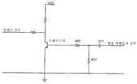
도 6은 상기 제1 필터 회로(40)의 실시예들 중의 하나를 예시한다. 이 실시예에서, 저항 R17 및 커패시터 C17에 의해 구성된 어셈블리는 고역 통과 필터를 구성하며, 예를 들어, 본 발명의 제시가 선형 컴프레서에 채용되는 경우에 있어서 5KHz 이하의 주파수를 잘라내도록 구성되어야 한다. 저항 R27은 상기 센싱 어셈블리(11)에 의해 읽혀지는 신호를 증폭시키는 트랜지스터(77)를 바탕으로 전달되는 전류를 제한하는 기능을 갖는다. 6 illustrates one of the embodiments of the
도 5는 제2 필터 회로(42)의 실시예들 중의 하나를 예시한다. 이 실시예에서, 저항 R46 및 커패시터 C46에 의해 형성된 어셈블리는 고역 통과 필터로서 동작하고, 반면 커패시터 C36 및 저항 R36으로 형성된 어셈블리는 저역 통과 필터를 형성하 고, 두 어셈블리의 중첩은 저역 통과 필터를 야기할 것이다. 본 발명의 제시가 선형 컴프레서(10')에 채용되는 경우에, 상기 센싱 어셈블리(11)에 의해 읽혀진 신호로부터 500Hz 보다 높은 주파수와 5Hz 보다 낮은 주파수를 제거하는 그러한 필터들을 구성하도록 선택될 수 있다. 이와 같이, 상기 제2 필터 회로(42)의 출력은 피스톤 변위에 해당할 것이다. 5 illustrates one of the embodiments of the
상기 센싱 어셈블리(11)에 의해 읽혀지고 상기 제1 필터 회로(40) 및 상기 제2 필터 회로(42)에 의해 처리되는 신호들은 상기 전자식 제어기(16)로 전달되며, 피스톤 임팩트를 방지하기 위해 동작할 것이다. The signals read by the
상기 제1 필터 회로(40)에 의해 처리되는 신호는, 상기 후자가 두(binary) 방식으로 해석될 수 있기 때문에, 상기 전자식 제어기(16)로 바로 공급될 수 있다. 이는, 피스톤이 최대 스트로크 지점을 통과하는 때, 임팩트가 발생할 수 있거나 임박하였고, 그 변위 스트로크가 감소되어야 한다는 것을 상기 센싱 어셈블리(11)의 신호가 신호하는 경우의 도 7에서 관찰될 수 있다. The signal processed by the
상기 제2 필터 회로(42)에 의해 처리되는 신호는 다양한 진폭을 갖는데, 이는 실린더 내의 피스톤 변위에 해당하기 때문이다. 이러한 방식으로, 상기 신호는 상기 전자식 제어기(16)에 전달되기 전에 비교기(45)를 통해 통과하여야만 한다. 상기 비교기(45)는 유체 펌프(10)의 특성에 따라 조절되어야만 하는 기준 전압에 연결된다. 선택적으로, 상기 비교기(45) 대신에 A/D 컨버터가 이용될 수 있다. The signal processed by the
도 7에서 관찰될 수 있는 바와 같이, 일단 상기 센싱 어셈블리(11)가 최대 스트로크 값을 검지하면, 이 상황을 상기 전자식 제어기(16)로 신호하여야 한다. As can be seen in FIG. 7, once the sensing
예를 들어, 압전(PZT 또는 piezoelectric) 센서를 이용함에 의해 상기 센싱 어셈블리를 구현하기 위해, 피스톤이 각 스트로크 말단과 충돌하는 때, 고주파수(5kHz 초과) 성분들이 발생하며, 상기 제1 필터 회로(40)는 상기 센싱 어셈블리(11)에 의해 발생된 신호의 이러한 고주파수 성분들만을 선택하여야 하는데, 이는 이들이 실린더 상부 또는 스트로크 말단과의 상기 피스톤의 기계적 임팩트를 식별하기 때문이다. 한편, 상기 제2 필터 회로(42)는 상기 시스템의 동작 주파수(50 또는 60 Hz)를 선택하고, DC 또는 고주파수 성분을 제거하기 위해 조정되어야 하는데, 이는 상기 스트로크의 정보가 동작 주파수 내에 있을 것이기 때문이다. 명백하게, 압전 센서의 현재의 예시와 관련된 기술은 본 발명의 제시에 대한 제한적 요소로서 취해져서는 안 되며, 이는 다른 타입의 센서들이 상기 센싱 어셈블리(11)를 구현하기 위해 이용될 수 있으며, 예를 들어, 다른 타입의 필터들이 존재할 수 있기 때문이다. For example, to implement the sensing assembly by using a piezoelectric (PZT or piezoelectric) sensor, high frequency (greater than 5 kHz) components occur when the piston collides with each stroke end, and the
두 센서를 이용함에 의해:By using two sensors:
이 변형예에 따라서는, 다른 기능을 갖는 두 센서를 구비한 유체 펌프(10)를 제공하는 것으로 선택될 수 있다: 상기 전자식 제어기(16)에 의해 해석될 신호를 제공하는, 임팩트 센서(35) 및 피스톤 위치 센서이다.According to this variant, it may be selected to provide a
이 실시예에서, 상기 신호 처리 모듈(31)은, 도 3a에서 도시된 바와 같이, 상기 센서(35, 36) 각각으로부터 신호를 받을 것이며, 상기 정보를 상기 전자식 제어기(16)로 전달하기 위해 하나의 센서를 이용하는 경우에 기재된 것과 동일한 방식으로 진행되어야 한다. In this embodiment, the
상기 위치 센서에 의해 읽혀진 신호를 해석하는 방법들 중의 하나가 특허문서 BR9907432-0에 기술되어 있으나, 다른 형식의 모니터링이 이용될 수 있다. Although one of the methods of interpreting the signal read by the position sensor is described in patent document BR9907432-0, other forms of monitoring may be used.
센서의 타입 및 유체 펌프(10)에서의 각 배치:Type of sensor and each arrangement in fluid pump 10:
임팩트 센서로서, 이미 앞서 언급된 바와 같은 가속도계 타입 센서가 예를 들어 이용될 수 있다. 이러한 경우에, 상기 임팩트 센서(35)는 상기 유체 펌프(10)의 실린더에 연결되어야 하며, 바람직하게는, 피스톤 임팩트가 감지될 수 있도록, 상기 유체 펌프(10)의 실린더와 함께 그러한 가속도계를 고정하여야만 한다. As the impact sensor, an accelerometer type sensor as already mentioned above can be used, for example. In this case, the
상기 위치 센서(36)가 예를 들어, 자기 센서에 의해 구현될 수 있다. 이러한 타입의 센서들은, 전자식 제어기(16)에 의해 측정가능한 파를 발생시키기 위해, 상기 피스톤의 접근에 의해 방해받는 자계를 발산한다. 상기 위치 센서(36)는, 예를 들어, 상기 유체 펌프의 실린더 내에 배열될 수 있다. The
유체 펌프(10) 제어 방법How to Control the Fluid Pump (10)
상기 유체 펌프(10) 및 선형 컴프레서, 또는 냉장고 또는 에어컨 시스템을 구성할 수 있는 냉각기를 제어하는 시스템을 구동하기 위하여, 도 8에 도시되어 있는 이하의 단계들이 수행되어야 한다. In order to drive the
상기 유체 펌프(10)가 트리거 신호를 수신하는 때마다 또는 상기 유체 펌프가 기동하는 때마다, 앞서 기술된 바와 같이, 최소한의 스트로크로 상기 실린더 내에서의 피스톤 변위를 야기하고, 연속적으로 상기 변위의 크기를 증가시킴에 의해, 상기 유체 펌프(10)를 기동하여야 한다. Each time the
이후, 피스톤 스트로크는 가능한 임팩트를 검지하기 위해 모니터링되어야 하 며, 임팩트가 발생하지 않는 경우, 상기 시스템이 안정화되었는지 결론짓기 위해, 즉, 이 기간동안 임팩트가 발생하지 않을 것인지를 판단하기 위해 안정화 시간이 주어져야 한다. The piston stroke should then be monitored to detect possible impacts, and if no impacts occur, the stabilization time is set to conclude that the system has stabilized, i.e. to determine whether no impacts will occur during this period. Should be given.
"임팩트"라는 용어와 관련하여, 그러한 단계를 모니터링하는데 이용되는 센서의 타입에 따를 것이므로, "임팩트"가 상기 피스톤의 임팩트에 임박한 것(imminent impact)일 수 있음이 고려되어야 한다. 가속도계 타입 센서의 이용의 경우, 상기 스트로크 말단과의 피스톤 임팩트는 충돌에 해당할 것이다. 반면, 예를 들어, 문서 BR0001404-4 및 BR0200898-0에 기술된 바와 같이, 접촉형 센서가 이용되는 경우에, 또는 자기 센서의 경우에서조차, 임팩트의 상황에서는, 각 스트로크 말단과의 피스톤의 실제 충돌은 없을 것이나, 앞서 기술된 바와 같은 임팩트에 임박한 것 만이 있을 것이다. With regard to the term "impact", it should be considered that the "impact" may be an impact on the impact of the piston, as it will depend on the type of sensor used to monitor such steps. In the case of the use of an accelerometer type sensor, the piston impact with the stroke end would correspond to a collision. On the other hand, as described, for example, in documents BR0001404-4 and BR0200898-0, when contact sensors are used, or even in the case of magnetic sensors, in the context of impact, the actual collision of the piston with each stroke end. There will be no, but there will only be an impending impact as described above.
안정화 시간의 단계 이후에, 상기 시스템이 안정화되면, 즉, 상기 안정화 시간동안 임팩트가 발생하지 않으면, 상기 피스톤 스트로크는 다시 증가되어야 하며, 이러한 루틴은 임팩트가 검지될 때까지 반복되어야 한다. After the step of stabilization time, if the system is stabilized, that is, no impact occurs during the stabilization time, the piston stroke must be increased again and this routine must be repeated until an impact is detected.
상기 안정화 시간의 값은 이용될 유체 펌프의 타입에 의존적일 것이다. 선형 컴프레서에서의 이용의 경우, 이 안정화 시간은 몇 초 부터 몇 분까지의 크기의 정도일 것이며, 전형적인 값은 수십 초일 것이다. 상기 안정화 시간의 값의 크기의 정확한 지정은 피스톤 스트로크의 모니터링 함수로서 결정될 수 있다. 따라서, 외부 시스템에 의해 모니터링 될 피스톤 스트로크에 의해 결정된 크기의 안정화 시간이 적용될 수 있다. 상기 피스톤 스트로크가 모니터링될 수 있으며, 더 이상의 임팩트가 발생하지 않을 것이라는 것이 확실한 때 변위 크기에서의 증가가 유효하다.The value of the stabilization time will depend on the type of fluid pump to be used. For use in linear compressors, this settling time will be on the order of a few seconds to a few minutes, typical values of tens of seconds. The exact designation of the magnitude of the value of the stabilization time can be determined as a monitoring function of the piston stroke. Thus, a stabilization time of the size determined by the piston stroke to be monitored by the external system can be applied. The increase in displacement magnitude is valid when it is certain that the piston stroke can be monitored and no further impact will occur.
다음 단계에서, 임팩트의 검지 후에, 상기 피스톤 스트로크는 감소되어야 하며, 유체 펌프(10)에서의 피스톤 스트로크의 최대값이 설정된다. 이 단계 후에, 최소한의 스트로크로 펌프가 시작되어야만 하는 때, 앞서 기술된 바와 같이, 전기적 또는 기계적 오류가 발생하지 않는 조건하에, 상기 유체 펌프(10)는 일정한 방식으로 구동된다. In the next step, after detection of the impact, the piston stroke has to be reduced and the maximum value of the piston stroke at the
변위 스트로크의 감소시, 컴프레서의 효율이 고려되는 한, 안전하고 동시에 적절한 변위만큼 상기 피스톤이 움직일 것이라는 것을 확실히 하기 위해, 피스톤 변위의 최대값은 상기 전자식 제어기(16)에 저장되어야 하며, 이 순간부터, 임팩트로부터 얻어진 변위의 최대값을 갖고 피스톤 스트로크의 모니터링을 시작한다. 상기 피스톤 변위의 크기를 예를 들어, 퍼센트로 감소시키기 위해 선택될 수 있다. When reducing the displacement stroke, the maximum value of the piston displacement must be stored in the
이와 같이, 피스톤 변위의 최대값이 일단 알려지면, 상기 전자식 제어기(16)는 상기 유체 펌프가 상기 제한 이상에서 동작하도록 허용하지 않을 것이고, 그런경우에도 더 이상의 임팩트가 발생하는 경우, 상기 전자식 제어기(16)는 상기 시스템을 재계량(recalibrate)하여야, 즉, 상기 피스톤 변위를 최소 스트로크에서 시작하여 연속적으로 증가시켜야 한다. 이것이 가능하도록 하기 위해, 상기 시스템은 계량 루틴 동안 뿐만이 아니라 항상 동작중이어야 한다. As such, once the maximum value of piston displacement is known, the
앞서 언급된 바와 같이, 상기 유체 펌프(10)를 최소 스트로크로 기동하는 단계는 주기적으로 수행될 수 있으며, 이러한 방식으로, 끊임없이 상기 유체 펌프 (10)를 최대 피스톤 스트로크로 계량할 수 있다. As mentioned above, the step of starting the
선형 Linear 컴프레서로의To the compressor 응용: Applications:
앞서 언급된 바와 같이, 각각의 제어 방법 뿐만 아니라 유체 펌프(10)를 제어하는 제어 시스템은 특히 선형 컴프레서(10')를 포함하는 응용들을 위한 것이며, 이는 상기 선형 컴프레서가 실린더 내에 위치변화가능하게 위치한 피스톤을 구비하기 때문이며, 상기 실린더는 피스톤 변위 스트로크를 갖고, 스트로크 말단을 구비한다.As mentioned above, the control system for controlling the
상기 실린더 내에서 피스톤이 자유롭게 진동하고, 상기 어셈블링 단계에서의 허용오차들이 조정되어야만 하므로, 상기 경우에서의 응용은 특히 유용하다. The application in this case is particularly useful because the piston vibrates freely in the cylinder and the tolerances in the assembling step must be adjusted.
본 발명의 장점들은, 장비들이 켜질 때마다, 유체 펌프(10)의 계량이 예견되기 때문에, 전기적 및 기계적 부품들의 허용오차가 더 커질 수 있다는 것이다. 이러한 방식으로, 유체 펌프(10)의 조립 및 제조 동안의 계량 단계가 제거될 수 있어서, 시간에서의 이득 및 결과적으로 재정적 이익을 낳게 된다. The advantages of the present invention are that the tolerance of electrical and mechanical components can be greater because the metering of the
오류가 검지되는 때마다 자동 조정의 가능성은 또한, 종래 기술의 제시에 따라 조립되는 것들과 비교할 때, 보다 안정된 유체 펌프(10)를 낳게 된다.The possibility of automatic adjustment each time an error is detected also results in a more
게다가, 상기 시스템의 계량이 예견됨과 같이, 보다 덜 정확한 센서 또는 이득 및 오프셋이 감소한 센서를 이용하는 것이 가능하다. In addition, it is possible to use less accurate sensors or sensors with reduced gain and offset as the metering of the system is foreseen.
유체 펌프(10)의 효율의 최적화가 중요한데, 이는 상기 피스톤이 스트로크 말단에 가깝게 동작할 수 있어서, 최대 효율을 야기하기 때문이다. Optimization of the efficiency of the
피스톤 변위 및 임팩트의 발생을 동시에 모니터링하는 하나의 센서를 이용하는 가능성은 또한 경제적 이득을 낳는데, 이는 부품들의 절약뿐만 아니라, 상기 유체 펌프(10) 상에 하나 이상의 센서를 삽입할 필요가 제거되기 때문이다. 또한, 다른 피스톤-이동 시스템과의 통합 또한 가능하다. The possibility of using one sensor to simultaneously monitor the displacement of the piston and the impact is also an economical benefit, as it eliminates the need for inserting one or more sensors on the
지금까지 바람직한 실시예가 기술되었으며, 본 발명의 범위는, 다른 가능한 변화를 포함하며, 가능한 동등물을 포함하는 첨부된 청구항들의 내용에 의해서만 제한된다는 것으로 이해되어야 한다. Preferred embodiments have been described so far, and it should be understood that the scope of the present invention is limited only by the content of the appended claims, including other possible variations and including possible equivalents.
Claims (31)
Applications Claiming Priority (3)
| Application Number | Priority Date | Filing Date | Title |
|---|---|---|---|
| BR0305458-6A BR0305458A (en) | 2003-12-05 | 2003-12-05 | Fluid pump control system, fluid pump control method, linear compressor and cooler |
| BRPI0305458--6 | 2003-12-05 | ||
| PCT/BR2004/000240 WO2005054676A1 (en) | 2003-12-05 | 2004-12-02 | A fluid pump controlling system and method |
Publications (2)
| Publication Number | Publication Date |
|---|---|
| KR20060121263A KR20060121263A (en) | 2006-11-28 |
| KR101167325B1 true KR101167325B1 (en) | 2012-07-19 |
Family
ID=34637802
Family Applications (1)
| Application Number | Title | Priority Date | Filing Date |
|---|---|---|---|
| KR1020067013220A Expired - Fee Related KR101167325B1 (en) | 2003-12-05 | 2004-12-02 | A fluid pump controlling system, a fluid pump controlling method, a linear compressor and a cooler |
Country Status (9)
| Country | Link |
|---|---|
| US (1) | US8333566B2 (en) |
| EP (1) | EP1709327B1 (en) |
| JP (2) | JP2007513280A (en) |
| KR (1) | KR101167325B1 (en) |
| CN (1) | CN100507268C (en) |
| BR (1) | BR0305458A (en) |
| DE (1) | DE602004021429D1 (en) |
| ES (1) | ES2324617T3 (en) |
| WO (1) | WO2005054676A1 (en) |
Families Citing this family (20)
| Publication number | Priority date | Publication date | Assignee | Title |
|---|---|---|---|---|
| DE202005013089U1 (en) * | 2005-08-19 | 2007-01-04 | Prominent Dosiertechnik Gmbh | Magnetic dosing pump, with a pressure piece and push rod acting on a membrane, has a reference unit for them with a non-contact position sensor to give an actual position signal for a control setting against a nominal value profile |
| DE102005039772A1 (en) | 2005-08-22 | 2007-03-08 | Prominent Dosiertechnik Gmbh | solenoid |
| BRPI0705049B1 (en) * | 2007-12-28 | 2019-02-26 | Embraco Indústria De Compressores E Soluções Em Refrigeração Ltda | GAS COMPRESSOR MOVED BY A LINEAR MOTOR, HAVING AN IMPACT DETECTOR BETWEEN A CYLINDER AND PISTON, DETECTION METHOD AND CONTROL SYSTEM |
| BRPI0800251B1 (en) * | 2008-02-22 | 2021-02-23 | Embraco Indústria De Compressores E Soluções Em Refrigeração Ltda | linear compressor control system and method |
| US8428846B2 (en) * | 2009-09-30 | 2013-04-23 | Bombardier Recreational Products Inc. | Electronic oil pump |
| EP2469089A1 (en) * | 2010-12-23 | 2012-06-27 | Debiotech S.A. | Electronic control method and system for a piezo-electric pump |
| BRPI1103005A2 (en) * | 2011-06-06 | 2013-07-02 | Whirlpool Sa | compressor piston parameter detection system |
| KR101893630B1 (en) * | 2011-09-09 | 2018-08-30 | 그라코 미네소타 인크. | Reciprocating positive displacement pump with electric reversing motor |
| DE102013212419A1 (en) * | 2013-06-27 | 2014-12-31 | Robert Bosch Gmbh | Method for determining the injection rate |
| DE102013017944A1 (en) * | 2013-10-29 | 2015-04-30 | Linde Aktiengesellschaft | Method for knock control in a reciprocating compressor |
| US10208741B2 (en) * | 2015-01-28 | 2019-02-19 | Haier Us Appliance Solutions, Inc. | Method for operating a linear compressor |
| US10502201B2 (en) * | 2015-01-28 | 2019-12-10 | Haier Us Appliance Solutions, Inc. | Method for operating a linear compressor |
| US10317875B2 (en) * | 2015-09-30 | 2019-06-11 | Bj Services, Llc | Pump integrity detection, monitoring and alarm generation |
| US10174753B2 (en) | 2015-11-04 | 2019-01-08 | Haier Us Appliance Solutions, Inc. | Method for operating a linear compressor |
| US10830230B2 (en) | 2017-01-04 | 2020-11-10 | Haier Us Appliance Solutions, Inc. | Method for operating a linear compressor |
| US10670008B2 (en) | 2017-08-31 | 2020-06-02 | Haier Us Appliance Solutions, Inc. | Method for detecting head crashing in a linear compressor |
| US10641263B2 (en) | 2017-08-31 | 2020-05-05 | Haier Us Appliance Solutions, Inc. | Method for operating a linear compressor |
| US11255318B2 (en) * | 2017-11-10 | 2022-02-22 | Motor Components, Llc | Electric control module solenoid pump |
| FR3115335B1 (en) * | 2020-10-19 | 2022-12-09 | F2M | Pump comprising a variable stroke piston |
| CN114810726B (en) * | 2022-04-26 | 2024-01-16 | 杭州新亚低温科技有限公司 | Driving system of cryogenic liquid pump with displacement monitoring function |
Citations (3)
| Publication number | Priority date | Publication date | Assignee | Title |
|---|---|---|---|---|
| US6176683B1 (en) | 1999-04-26 | 2001-01-23 | Lg Electronics, Inc. | Output control apparatus for linear compressor and method of the same |
| US20030161734A1 (en) | 2002-02-28 | 2003-08-28 | Samsung Electronics Co., Ltd. | Apparatus and method for controlling linear compressor |
| US20030219341A1 (en) | 2000-04-04 | 2003-11-27 | Dovey Stephen J. | Reciprocating machines |
Family Cites Families (6)
| Publication number | Priority date | Publication date | Assignee | Title |
|---|---|---|---|---|
| US4179630A (en) * | 1976-11-04 | 1979-12-18 | Tecumseh Products Company | Linear compressor |
| US4502842A (en) * | 1983-02-02 | 1985-03-05 | Colt Industries Operating Corp. | Multiple compressor controller and method |
| US5224835A (en) * | 1992-09-02 | 1993-07-06 | Viking Pump, Inc. | Shaft bearing wear detector |
| KR100367605B1 (en) * | 2000-11-29 | 2003-01-14 | 엘지전자 주식회사 | Driving control apparatus for linear compressor using pattern recognition |
| US6536326B2 (en) * | 2001-06-15 | 2003-03-25 | Sunpower, Inc. | Control system and method for preventing destructive collisions in free piston machines |
| KR100411786B1 (en) * | 2001-09-03 | 2003-12-24 | 삼성전자주식회사 | Apparatus and method for controlling linear compressor |
-
2003
- 2003-12-05 BR BR0305458-6A patent/BR0305458A/en not_active IP Right Cessation
-
2004
- 2004-12-02 EP EP04801141A patent/EP1709327B1/en not_active Expired - Lifetime
- 2004-12-02 DE DE602004021429T patent/DE602004021429D1/en not_active Expired - Lifetime
- 2004-12-02 ES ES04801141T patent/ES2324617T3/en not_active Expired - Lifetime
- 2004-12-02 CN CNB2004800414497A patent/CN100507268C/en not_active Expired - Fee Related
- 2004-12-02 KR KR1020067013220A patent/KR101167325B1/en not_active Expired - Fee Related
- 2004-12-02 JP JP2006541761A patent/JP2007513280A/en active Pending
- 2004-12-02 WO PCT/BR2004/000240 patent/WO2005054676A1/en not_active Ceased
- 2004-12-02 US US10/596,239 patent/US8333566B2/en not_active Expired - Fee Related
-
2011
- 2011-09-29 JP JP2011214036A patent/JP5497719B2/en not_active Expired - Fee Related
Patent Citations (3)
| Publication number | Priority date | Publication date | Assignee | Title |
|---|---|---|---|---|
| US6176683B1 (en) | 1999-04-26 | 2001-01-23 | Lg Electronics, Inc. | Output control apparatus for linear compressor and method of the same |
| US20030219341A1 (en) | 2000-04-04 | 2003-11-27 | Dovey Stephen J. | Reciprocating machines |
| US20030161734A1 (en) | 2002-02-28 | 2003-08-28 | Samsung Electronics Co., Ltd. | Apparatus and method for controlling linear compressor |
Also Published As
| Publication number | Publication date |
|---|---|
| JP2007513280A (en) | 2007-05-24 |
| CN100507268C (en) | 2009-07-01 |
| US20070276544A1 (en) | 2007-11-29 |
| CN101040118A (en) | 2007-09-19 |
| BR0305458A (en) | 2005-08-30 |
| JP2012031868A (en) | 2012-02-16 |
| DE602004021429D1 (en) | 2009-07-16 |
| JP5497719B2 (en) | 2014-05-21 |
| ES2324617T3 (en) | 2009-08-11 |
| EP1709327A1 (en) | 2006-10-11 |
| KR20060121263A (en) | 2006-11-28 |
| WO2005054676A1 (en) | 2005-06-16 |
| US8333566B2 (en) | 2012-12-18 |
| EP1709327B1 (en) | 2009-06-03 |
Similar Documents
| Publication | Publication Date | Title |
|---|---|---|
| KR101167325B1 (en) | A fluid pump controlling system, a fluid pump controlling method, a linear compressor and a cooler | |
| EP2250373B1 (en) | System and method of controlling a linear compressor | |
| JP3075475B1 (en) | Output control device for linear compressor and control method therefor | |
| JP5603249B2 (en) | Method for detecting impact between cylinder and linear motor drive piston, detector for impact between cylinder and linear motor drive piston, gas compressor, control system for linear motor drive cylinder / piston set | |
| US10327083B2 (en) | MEMS sound transducer with closed control system | |
| KR20130041119A (en) | A control method for a resonant linear compressor and an electronic control system for a resonant linear compressor applied to a cooling system | |
| KR101079007B1 (en) | A linear-compressor control system a method of controlling a linear compressor a linear compressor and cooling system | |
| KR20060119924A (en) | Linear motor controller | |
| JPH09112439A (en) | Driver of linear compressor | |
| JP2006515738A5 (en) | ||
| JP2019027912A (en) | Abnormality diagnosis device | |
| JPH08284843A (en) | Vibrating type compressor | |
| JP2018031335A (en) | Compressor | |
| BRPI0305458B1 (en) | “Fluid Pump Control System, Fluid Pump and Coolant Control Method” | |
| KR100246406B1 (en) | Cooling force control circuit of linear compressor | |
| JP2018155210A (en) | Fluid machine | |
| KR20050104434A (en) | Linear compressor |
Legal Events
| Date | Code | Title | Description |
|---|---|---|---|
| PA0105 | International application |
St.27 status event code: A-0-1-A10-A15-nap-PA0105 |
|
| PG1501 | Laying open of application |
St.27 status event code: A-1-1-Q10-Q12-nap-PG1501 |
|
| R18-X000 | Changes to party contact information recorded |
St.27 status event code: A-3-3-R10-R18-oth-X000 |
|
| A201 | Request for examination | ||
| P11-X000 | Amendment of application requested |
St.27 status event code: A-2-2-P10-P11-nap-X000 |
|
| P13-X000 | Application amended |
St.27 status event code: A-2-2-P10-P13-nap-X000 |
|
| PA0201 | Request for examination |
St.27 status event code: A-1-2-D10-D11-exm-PA0201 |
|
| E902 | Notification of reason for refusal | ||
| PE0902 | Notice of grounds for rejection |
St.27 status event code: A-1-2-D10-D21-exm-PE0902 |
|
| P11-X000 | Amendment of application requested |
St.27 status event code: A-2-2-P10-P11-nap-X000 |
|
| P13-X000 | Application amended |
St.27 status event code: A-2-2-P10-P13-nap-X000 |
|
| E701 | Decision to grant or registration of patent right | ||
| PE0701 | Decision of registration |
St.27 status event code: A-1-2-D10-D22-exm-PE0701 |
|
| GRNT | Written decision to grant | ||
| PR0701 | Registration of establishment |
St.27 status event code: A-2-4-F10-F11-exm-PR0701 |
|
| PR1002 | Payment of registration fee |
St.27 status event code: A-2-2-U10-U12-oth-PR1002 Fee payment year number: 1 |
|
| PG1601 | Publication of registration |
St.27 status event code: A-4-4-Q10-Q13-nap-PG1601 |
|
| FPAY | Annual fee payment |
Payment date: 20150630 Year of fee payment: 4 |
|
| PR1001 | Payment of annual fee |
St.27 status event code: A-4-4-U10-U11-oth-PR1001 Fee payment year number: 4 |
|
| LAPS | Lapse due to unpaid annual fee | ||
| PC1903 | Unpaid annual fee |
St.27 status event code: A-4-4-U10-U13-oth-PC1903 Not in force date: 20160714 Payment event data comment text: Termination Category : DEFAULT_OF_REGISTRATION_FEE |
|
| PC1903 | Unpaid annual fee |
St.27 status event code: N-4-6-H10-H13-oth-PC1903 Ip right cessation event data comment text: Termination Category : DEFAULT_OF_REGISTRATION_FEE Not in force date: 20160714 |