KR101154358B1 - Improvements in and relating to fluid filled devices - Google Patents
Improvements in and relating to fluid filled devices Download PDFInfo
- Publication number
- KR101154358B1 KR101154358B1 KR1020057015620A KR20057015620A KR101154358B1 KR 101154358 B1 KR101154358 B1 KR 101154358B1 KR 1020057015620 A KR1020057015620 A KR 1020057015620A KR 20057015620 A KR20057015620 A KR 20057015620A KR 101154358 B1 KR101154358 B1 KR 101154358B1
- Authority
- KR
- South Korea
- Prior art keywords
- fluid
- volume
- region
- fluids
- adjacent
- Prior art date
- Legal status (The legal status is an assumption and is not a legal conclusion. Google has not performed a legal analysis and makes no representation as to the accuracy of the status listed.)
- Expired - Lifetime
Links
Images


Classifications
-
- G—PHYSICS
- G02—OPTICS
- G02B—OPTICAL ELEMENTS, SYSTEMS OR APPARATUS
- G02B26/00—Optical devices or arrangements for the control of light using movable or deformable optical elements
- G02B26/02—Optical devices or arrangements for the control of light using movable or deformable optical elements for controlling the intensity of light
-
- G—PHYSICS
- G11—INFORMATION STORAGE
- G11B—INFORMATION STORAGE BASED ON RELATIVE MOVEMENT BETWEEN RECORD CARRIER AND TRANSDUCER
- G11B7/00—Recording or reproducing by optical means, e.g. recording using a thermal beam of optical radiation by modifying optical properties or the physical structure, reproducing using an optical beam at lower power by sensing optical properties; Record carriers therefor
- G11B7/12—Heads, e.g. forming of the optical beam spot or modulation of the optical beam
- G11B7/135—Means for guiding the beam from the source to the record carrier or from the record carrier to the detector
- G11B7/1372—Lenses
- G11B7/1374—Objective lenses
-
- G—PHYSICS
- G02—OPTICS
- G02B—OPTICAL ELEMENTS, SYSTEMS OR APPARATUS
- G02B26/00—Optical devices or arrangements for the control of light using movable or deformable optical elements
- G02B26/004—Optical devices or arrangements for the control of light using movable or deformable optical elements based on a displacement or a deformation of a fluid
- G02B26/005—Optical devices or arrangements for the control of light using movable or deformable optical elements based on a displacement or a deformation of a fluid based on electrowetting
-
- G—PHYSICS
- G02—OPTICS
- G02B—OPTICAL ELEMENTS, SYSTEMS OR APPARATUS
- G02B27/00—Optical systems or apparatus not provided for by any of the groups G02B1/00 - G02B26/00, G02B30/00
- G02B27/0025—Optical systems or apparatus not provided for by any of the groups G02B1/00 - G02B26/00, G02B30/00 for optical correction, e.g. distorsion, aberration
- G02B27/0068—Optical systems or apparatus not provided for by any of the groups G02B1/00 - G02B26/00, G02B30/00 for optical correction, e.g. distorsion, aberration having means for controlling the degree of correction, e.g. using phase modulators, movable elements
-
- G—PHYSICS
- G02—OPTICS
- G02B—OPTICAL ELEMENTS, SYSTEMS OR APPARATUS
- G02B3/00—Simple or compound lenses
- G02B3/12—Fluid-filled or evacuated lenses
- G02B3/14—Fluid-filled or evacuated lenses of variable focal length
-
- G—PHYSICS
- G11—INFORMATION STORAGE
- G11B—INFORMATION STORAGE BASED ON RELATIVE MOVEMENT BETWEEN RECORD CARRIER AND TRANSDUCER
- G11B7/00—Recording or reproducing by optical means, e.g. recording using a thermal beam of optical radiation by modifying optical properties or the physical structure, reproducing using an optical beam at lower power by sensing optical properties; Record carriers therefor
- G11B7/12—Heads, e.g. forming of the optical beam spot or modulation of the optical beam
- G11B7/135—Means for guiding the beam from the source to the record carrier or from the record carrier to the detector
- G11B7/1365—Separate or integrated refractive elements, e.g. wave plates
- G11B7/1369—Active plates, e.g. liquid crystal panels or electrostrictive elements
-
- G—PHYSICS
- G02—OPTICS
- G02B—OPTICAL ELEMENTS, SYSTEMS OR APPARATUS
- G02B27/00—Optical systems or apparatus not provided for by any of the groups G02B1/00 - G02B26/00, G02B30/00
- G02B27/0025—Optical systems or apparatus not provided for by any of the groups G02B1/00 - G02B26/00, G02B30/00 for optical correction, e.g. distorsion, aberration
- G02B27/005—Optical systems or apparatus not provided for by any of the groups G02B1/00 - G02B26/00, G02B30/00 for optical correction, e.g. distorsion, aberration for correction of secondary colour or higher-order chromatic aberrations
-
- G—PHYSICS
- G11—INFORMATION STORAGE
- G11B—INFORMATION STORAGE BASED ON RELATIVE MOVEMENT BETWEEN RECORD CARRIER AND TRANSDUCER
- G11B7/00—Recording or reproducing by optical means, e.g. recording using a thermal beam of optical radiation by modifying optical properties or the physical structure, reproducing using an optical beam at lower power by sensing optical properties; Record carriers therefor
- G11B2007/0003—Recording, reproducing or erasing systems characterised by the structure or type of the carrier
- G11B2007/0006—Recording, reproducing or erasing systems characterised by the structure or type of the carrier adapted for scanning different types of carrier, e.g. CD & DVD
-
- G—PHYSICS
- G11—INFORMATION STORAGE
- G11B—INFORMATION STORAGE BASED ON RELATIVE MOVEMENT BETWEEN RECORD CARRIER AND TRANSDUCER
- G11B7/00—Recording or reproducing by optical means, e.g. recording using a thermal beam of optical radiation by modifying optical properties or the physical structure, reproducing using an optical beam at lower power by sensing optical properties; Record carriers therefor
- G11B7/12—Heads, e.g. forming of the optical beam spot or modulation of the optical beam
- G11B7/135—Means for guiding the beam from the source to the record carrier or from the record carrier to the detector
- G11B7/1372—Lenses
- G11B2007/13727—Compound lenses, i.e. two or more lenses co-operating to perform a function, e.g. compound objective lens including a solid immersion lens, positive and negative lenses either bonded together or with adjustable spacing
Landscapes
- Physics & Mathematics (AREA)
- Optics & Photonics (AREA)
- General Physics & Mathematics (AREA)
- Chemical & Material Sciences (AREA)
- Crystallography & Structural Chemistry (AREA)
- Mechanical Light Control Or Optical Switches (AREA)
- Optical Head (AREA)
- Mechanical Optical Scanning Systems (AREA)
- Physical Or Chemical Processes And Apparatus (AREA)
Abstract
n가지 유체의 용적(80, 87; 200, 230; 320, 330, 332; 420, 422, 430, 432)을 포함하는 밀봉된 캐비티(210)를 구비한 장치(100; 200; 300; 400)가 개시되는데, 이때, n이 정수로서 n≥2이다. 각각의 유체의 용적이 모든 인접하는 유체의 용적과 혼합되지 않는다. 상기 캐비티(210)가 n개의 연속적인 영역(60, 170; 260, 270; 360, 362, 370; 460, 462, 470, 472)으로 분할된 내부 표면에 의해 한정되고, 각각의 연속적인 영역이 유체의 용적들 각각의 유체 용적에 대응하여 이 유체 용적과 접촉한다. 각각의 유체의 용적이, 대응하는 영역에 인접한 연속적인 영역들 중에서 어느 한 개의 영역보다, 대응하는 연속적인 영역에 선호하여 부착되도록, 각각의 영역의 젖음성이 설정된다.Apparatus 100; 200; 300; 400 with a sealed cavity 210 comprising volumes of n fluids 80, 87; 200, 230; 320, 330, 332; 420, 422, 430, 432 Is disclosed wherein n is n ≧ 2 as an integer. The volume of each fluid does not mix with the volume of all adjacent fluids. The cavity 210 is defined by an inner surface divided into n consecutive regions 60, 170; 260, 270; 360, 362, 370; 460, 462, 470, 472, each successive region being Each of the volumes of fluid is in contact with the fluid volume. The wettability of each region is set such that the volume of each fluid preferentially attaches to the corresponding continuous region, rather than any one of successive regions adjacent to the corresponding region.
유체 충전, 전기습윤, 캐비티, 분할, 광학주사장치 Fluid filling, electrowetting, cavity, splitting, optical scanning device
Description
본 발명은, 유체 충전 장치에 관한 것으로, 더욱 구체적으로는 밀봉된 캐비티(cavity)를 구비한 장치에 관한 것이다. 본 발명은 전기습윤(electrowetting) 장치에 사용하는데 매우 적합하다.TECHNICAL FIELD The present invention relates to a fluid filling device, and more particularly to a device having a sealed cavity. The present invention is well suited for use in electrowetting devices.
유체 충전 장치는 적어도 2가지의 유체를 포함하는 장치(즉, 다중유체 충전 장치)로서, 일반적으로 이 장치는 유체들 중에서 적어도 1가지 유체의 용적을 변위(위치나 형상의 변화)시킴으로써 특정한 기능을 수행하도록 구성된다.A fluid filling device is a device containing at least two fluids (i.e., a multifluid filling device), which generally provides a specific function by displacing (change in position or shape) the volume of at least one of the fluids. Configured to perform.
광학 유체 충전 장치는, 예를 들면, 렌즈, 조리개, 격자, 셔터, 광 스위치 또는 필터 등의 기능을 수행할 수 있다. 광학 유체 충전 장치들의 예와, 전기습윤 등에 의해 유체를 변위시킬 수 있는 다양한 방법은 WO 02/069016에 기재되어 있다.The optical fluid filling device may perform a function such as a lens, an iris, a grating, a shutter, an optical switch or a filter, for example. Examples of optical fluid filling devices and various methods of displacing the fluid by electrowetting and the like are described in WO 02/069016.
전기습윤장치들은 전기습윤 현상을 이용하여 동작하는 장치이다. 전기습윤에서는, 인가된 전압을 사용하여 3상 접촉각이 변화된다. 3상은 2개의 유체와 1개의 고체를 구성한다. 유체라는 용어는 액체와 기체를 모두 포함한다. 보통, 최소한 제 1 유체는 액체이고, 제 2 유체는 액체이거나 기체 또는 증가일 수 있다.Electrowetting devices are devices that operate using electrowetting phenomena. In electrowetting, the three-phase contact angle is changed using an applied voltage. Three phases make up two fluids and one solid. The term fluid includes both liquids and gases. Usually, at least the first fluid is a liquid and the second fluid can be a liquid or a gas or an increase.
EP 1,069,450에는, 전기습윤 효과를 이용하여 가변밀도 광학 필터로서 기능하는 광학장치가 개시되어 있다. 도 1은 이와 같은 종래의 광학장치(90)의 단면도이다. 광학장치(90)는 밀봉된 공간(92)(즉, 챔버 또는 캐비티) 내부에 감금된 2가지 혼합할 수 없는 유체들(80, 87)을 갖는다. 혼합할 수 없다는 용어는, 2가지 유체가 섞이지 않는다는 것을 나타낸다. 제 1 유체(80)는 절연체(예를 들면, 실리콘 오일)이고, 제 2 유체(87)는 전기도전성을 갖는다(예를 들면, 물과 에틸 알콜의 혼합물). 제 1 유체(80)와 제 2 유체(87)는 서로 다른 광 투과율을 갖는다.EP 1,069,450 discloses an optical device which functions as a variable density optical filter using the electrowetting effect. 1 is a cross-sectional view of such a conventional
전원(40)에서 주어진 전압이 2개의 전극(41, 42) 사이에 인가되어, 유체 87과 전극 42 사이에 전기장을 생성한다(절연층(50)은 제 2 전극 42가 도전성 제 2 유체에 접촉하는 것을 방지한다).A given voltage at the
제 2 유체(87)에 인가되는 전압을 변경함으로써, 제 1 유체(80)와 제 2 유체(87) 사이의 계면(85)이 변화되어, 광학장치의 총 투과율을 변경시킨다. 또한, 이와 유사한 구조를 이용하지만, 서로 다른 굴절률을 갖는 2가지 유체(80, 87)를 사용하는 가변렌즈를 제공하는 것도 공지되어 있다.By changing the voltage applied to the
도 1에 도시된 장치(90)는, 제 1 유체(20)를 배치시키기 위해, 친수제(70)의 고리에 의해 둘러싸인 절연층(50) 위에 직경 D1의 발수막(60)을 갖는다. 장치의 동작중에 계면(85)의 형상이 변한다. 형상의 변화는 유체 80이 발수층(60)으로부터 밀봉된 공간의 반대측 표면으로 신장되게 한다. 제 1 유체(80)가 반대측 표면에 부착되는 것을 방지하기 위해, 이 반대측 표면의 일부가 직경 D2를 갖는 친수막(72)의 층으로 코팅된다.The
계면(25)에 미치는 중력의 작용을 줄이기 위해, 2가지 유체들(80, 97)이 동일한 밀도를 가질 수도 있다.To reduce the effect of gravity on the
결국, 본 발명의 목적은, 개량된 전기습윤장치를 제공함에 있다. 본 발명의 또 다른 목적은, 특히 가속력을 받을 때, 향상된 안정성을 갖는 전기습윤장치를 제공함에 있다.After all, it is an object of the present invention to provide an improved electrowetting device. Another object of the present invention is to provide an electrowetting device with improved stability, especially when subjected to acceleration.
본 발명의 일면에 있어서, 본 발명은, n가지 유체의 용적을 포함하는 밀봉된 캐비티를 구비하되, n이 n≥2인 정수이고, 각각의 유체의 용적이 모든 인접하는 유체의 용적과 혼합되지 않으며, 상기 캐비티가 n개의 연속적인 영역으로 분할된 내부 표면에 의해 한정되고, 각각의 연속적인 영역이 유체의 용적들 각각의 유체 용적에 대응하여 이 유체 용적과 접촉하며, 각각의 유체의 용적이, 대응하는 영역에 인접한 연속적인 영역들 중에서 어느 한 개의 영역보다, 대응하는 연속적인 영역에 선호하여 부착되도록, 각각의 영역의 젖음성(wettability)이 설정되는 것을 특징으로 하는 장치를 제공한다.In one aspect of the invention, the invention has a sealed cavity comprising a volume of n fluids, where n is an integer such that n≥2 and the volume of each fluid is not mixed with the volumes of all adjacent fluids. The cavity is defined by an inner surface divided into n consecutive regions, each successive region contacting this fluid volume corresponding to the respective fluid volume of the volumes of fluid, the volume of each fluid being The wettability of each region is set such that the wettability of each region is set to preferentially attach to the corresponding continuous region, rather than any one of successive regions adjacent to the corresponding region.
이와 같은 구조를 갖는 밀봉된 캐비티를 제공함으로써, 유체 용적이 캐비티의 내부 표면의 부정확한 위치에 부착될 가능성이 크게 줄어든다. 그 결과, 가속력을 겪을 때의 장치의 안정성이 향상된다. 더구나, 한가지 유체에 용해된 소량의 다른 유체가 부정확한 표면에 응축되는 것이 방지된다.By providing a sealed cavity having such a structure, the likelihood that the fluid volume will adhere to an incorrect position of the interior surface of the cavity is greatly reduced. As a result, the stability of the device when subjected to acceleration is improved. Moreover, a small amount of other fluid dissolved in one fluid is prevented from condensing on the incorrect surface.
또 다른 국면에 있어서, 본 발명은, 광 기록매체의 정보층을 주사하는 광학주사장치로서, 이 장치가 방사빔을 발생하는 방사원과, 정보층에 방사빔을 수렴시키는 대물렌즈를 구비하고, 상기 광학주사장치가 n가지 유체의 용적을 포함하는 밀봉된 캐비티를 포함하는 장치를 구비하며, n이 정수로서 n≥2이고, 각각의 유체의 용적이 모든 인접하는 유체의 용적과 혼합되지 않으며, 상기 캐비티가 n개의 연속적인 영역으로 분할된 내부 표면에 의해 한정되고, 각각의 연속적인 영역이 유체의 용적들 각각의 유체 용적에 대응하여 이 유체 용적과 접촉하며, 각각의 유체의 용적이, 대응하는 영역에 인접한 연속적인 영역들 중에서 어느 한 개의 영역보다, 대응하는 연속적인 영역에 선호하여 부착되도록, 각각의 영역의 젖음성이 설정되는 것을 특징으로 하는 광학주사장치를 제공한다.In still another aspect, the present invention provides an optical scanning device for scanning an information layer of an optical record carrier, comprising: a radiation source for generating a radiation beam, and an objective lens for converging the radiation beam on the information layer; The optical scanning device has a device comprising a sealed cavity comprising a volume of n fluids, where n is an integer n ≧ 2, and the volume of each fluid is not mixed with the volumes of all adjacent fluids. The cavity is defined by an inner surface divided into n contiguous regions, each contiguous region contacting this fluid volume corresponding to the fluid volume of each of the volumes of fluid, the volume of each fluid being corresponding Characterized in that the wettability of each region is set so that it preferentially attaches to the corresponding continuous region rather than any one of successive regions adjacent to the region. It provides a learning injection device.
또 다른 국면에 있어서, 본 발명은, 장치를 제조하는 방법으로서, n이 정수로서 n≥2일 때, n개의 연속적인 영역으로 분할된 내부 표면을 갖는 캐비티를 형성하는 단계와, 각각의 유체의 용적이 모든 인접하는 유체 용적과 혼합되지 않아, 각각의 연속적인 영역이 유체의 용적들 각각의 유체 용적에 대응하여 이 유체 용적과 접촉하는 n가지 유체의 용적을 사용하여 캐비티를 충전하는 단계와, 상기 캐비티를 밀봉하는 단계를 포함하며, 각각의 유체의 용적이, 대응하는 영역에 인접한 연속적인 영역들 중에서 어느 한 개의 영역보다, 대응하는 연속적인 영역에 선호하여 부착되도록, 각각의 영역의 젖음성이 설정되는 것을 특징으로 하는 제조방법을 제공한다.In another aspect, the invention provides a method of manufacturing a device comprising the steps of: forming a cavity having an interior surface divided into n consecutive regions when n is n ≧ 2 as an integer, The volume is not mixed with all adjacent fluid volumes such that each successive region fills the cavity using the volumes of n fluids in contact with the fluid volume corresponding to the respective fluid volumes of the fluids, Sealing the cavity, wherein the wettability of each region is such that the volume of each fluid is preferentially attached to the corresponding continuous region rather than any one of successive regions adjacent to the corresponding region. It provides a manufacturing method characterized in that the set.
또 다른 국면에서, 본 발명은, 광 기록매체의 정보층을 주사하는 광학주사장치의 제조방법으로서, 방사빔을 발생하는 방사원을 형성하는 단계와, n가지 유체의 용적을 포함하는 밀봉된 캐비티를 구비하되, n이 정수로서 n≥2이고, 각각의 유체의 용적이 모든 인접하는 유체의 용적과 혼합되지 않으며, 상기 캐비티가 n개의 연속적인 영역으로 분할된 내부 표면에 의해 한정되고, 각각의 연속적인 영역이 유체의 용적들 각각의 유체 용적에 대응하여 이 유체 용적과 접촉하며, 각각의 유체의 용적이, 대응하는 영역에 인접한 연속적인 영역들 중에서 어느 한 개의 영역보다, 대응하는 연속적인 영역에 선호하여 부착되도록, 각각의 영역의 젖음성이 설정되는 장치를 형성하는 단계를 포함하는 것을 특징으로 하는 광학주사장치의 제조방법을 제공한다.In another aspect, the present invention provides a method of manufacturing an optical scanning device for scanning an information layer of an optical record carrier, the method comprising the steps of: forming a radiation source for generating a radiation beam; and a sealed cavity comprising volumes of n fluids. Provided that n is an integer n ≧ 2, that the volume of each fluid does not mix with the volume of all adjacent fluids, and that the cavity is defined by an inner surface divided into n consecutive regions, each continuous An area of contact is in contact with the fluid volume of each of the volumes of fluid and the volume of each fluid is in a corresponding continuous area, rather than any one of successive areas adjacent to the corresponding area. And forming a device in which the wettability of each region is set to be attached preferentially.
본 발명이 이해를 돕고, 이 실시예들이 실행되는 방식을 나타내기 위해, 이하 다음의 첨부도면을 참조하여 본 발명을 더욱 더 상세히 설명한다:BRIEF DESCRIPTION OF THE DRAWINGS In order to aid the understanding of the present invention and to show how these embodiments are implemented, the present invention will be described in more detail with reference to the following accompanying drawings:
도 1은 종래의 전기습윤장치의 단면도를 예시한 것이고,Figure 1 illustrates a cross-sectional view of a conventional electrowetting device,
도 2는 장치가 어떻게 교란될 수 있는지를 예시하는, 도 1에 도시된 장치의 단면도이며,2 is a cross-sectional view of the device shown in FIG. 1 illustrating how the device may be disturbed;
도 3은 본 발명의 제 1 실시예에 따른 장치의 단면도이고,3 is a sectional view of an apparatus according to a first embodiment of the present invention,
도 4는 본 발명의 또 다른 실시예에 따른 장치의 단면도이며,4 is a cross-sectional view of an apparatus according to another embodiment of the present invention,
도 5는 본 발명의 또 다른 실시예에 따른 장치의 단면도이고,5 is a cross-sectional view of an apparatus according to another embodiment of the present invention,
도 6은 본 발명의 또 다른 실시예에 따른 장치의 단면도이며,6 is a cross-sectional view of an apparatus according to another embodiment of the present invention,
도 7은 본 발명의 일 실시예에 따른 전기습윤장치를 포함하는 광 기록매체 주사장치를 나타낸 것이다.7 shows an optical record carrier scanning apparatus including an electrowetting device according to an embodiment of the present invention.
본 발명자들은, 도 1에 도시된 장치(90)가 교란될 수 있어, 이들 두가지 액체들이 원하는 위치가 전체가 머무르지 않는다는 것을 인식하였다. 예를 들면, 도 2에 도시된 것과 같이, 유체 80의 일부분(81)이 장치의 모서리에 체류하게 될 수도 있다. 이들 2가지 액체가 전혀 혼합이 불가능한 경우에 이와 같은 상황이 발생할 수 있다. 예를 들면, 유체 30 내부의 유체 20의 작은(서브마이크미터 크기의) 액적들이 장치(10)의 내부 표면에 고착되거나 축적될 수 있다. 이와 달리, 장치(90)가 가속력을 겪는 경우, 예를 들어, 장치를 흔들거나 장치를 낙하한 경우에, 이와 같은 상황이 일어날 수도 있다.The inventors have recognized that the
액체의 일부를 그것의 원하는 위치(또는, 실제로는, 전체 액체)로 변위시키는 것은 장치의 성능에 영향을 미치게 되므로 바람직하지 않다. 2가지 유체(80, 87) 사이에 있는 계면의 형태는 제 1 유체(80)의 용적에 부분적으로 의존한다. 그 결과, 제 1 유체(80)의 용적이 감소하면, 인가 전압의 함수로써의 계면(85)의 형상이 영향을 받게 된다. 이것은, 장치(90)의 성능을 변화시키고, 가변 필터(또는 유체들 20, 30의 특성에 따라, 렌즈)로서의 장치의 기능을 손상시킨다.Displacement of a portion of the liquid to its desired location (or, in fact, the entire liquid) is undesirable as it will affect the performance of the device. The shape of the interface between the two
본 발명자들은, 이와 같은 2가지 유체계에 대해, 2가지 개별적인 유체들 중에서 한가지 유체에 대응하며 이 한가지 유체를 선호하여 끌어당기는 2개의 별개의 영역으로 전체 내부 표면을 분할함으로써, 이와 같은 문제점을 극복할 수 있다는 것을 인식하였다. 이것은, 각각의 유체가 각각의 영역으로 이끌어지도록, 각각의 유체에 대해 서로 다른 젖음성을 갖는 장치의 영역들을 제공함으로써 달성된다. 젖음성은, 고체가 유체에 의해 적셔지는(덮이는) 정도이다. 용어 "분할된다"는, 표면 영역들이 인접(즉, 중간 영역들이 없는)할 뿐만 아니라, 연속(즉, 각각의 영역이 다른 유체를 이끌도록 배치된 개재하는 영역들을 포함하지 않는다)된다는 것을 의미한다. 이와 같은 중간 또는 개재하는 영역들의 최대폭은 유체들로 형성될 수 있는 액적의 직경보다 작다. 바람직하게는, 이와 같은 영역들의 최대폭은 100㎛보다 작고, 더욱 바람직하게는 10㎛보다 작다. 그 결과, 이 액적이 이러한 중간 영역에 접촉하게 되면, 중간 영역이 액적과의 충분한 접촉 영역을 제공하지 않으므로 이 액적이 부착되지 않는다.The inventors have overcome this problem for these two fluid systems by dividing the entire inner surface into two separate regions which correspond to one of the two individual fluids and prefer to attract one of these fluids. I recognized that I could. This is accomplished by providing regions of the device with different wetting properties for each fluid so that each fluid is directed to each region. Wetting is such that the solid is wetted (covered) by the fluid. The term "divided" means that the surface regions are not only adjacent (i.e. without intermediate regions), but also contiguous (i.e. each region does not include intervening regions arranged to lead other fluids). . The maximum width of these intermediate or intervening regions is smaller than the diameter of the droplets that can be formed into the fluids. Preferably, the maximum width of such regions is less than 100 μm, more preferably less than 10 μm. As a result, when this droplet comes into contact with this intermediate region, the droplet does not attach because the intermediate region does not provide a sufficient contact area with the droplet.
도 3은 본 발명의 제 1 실시예에 따른 장치(100)의 단면도를 나타낸 것이다. 이 장치(100)는 도 1 및 도 2에 예시된 장치(90)아 대체로 일치하며, 동일한 참조번호는 유사한 특징부를 나타낸다. 이 장치는, 비도전성의 비극성 제 1 유체(80)를 끌어당기도록 구성된 소수성 표면(60)의 직경 D1을 갖는 영역을 지닌다. 내부 표면의 나머지 부분은, 도전성 극성 유체(87)에 의해 선호하여 적셔지는(즉, 끌어당기는) 친수성 코팅(170)으로 덮인다. 이와 같은 구성은, 액체 용적(80)의 일부가 바람직하지 않게 내부 캐비티의 일부에 부착되는 도 2에 나타낸 형상을 방지한다. 그 대신에, 원치 않는 액적들이 형성되면, 이들 액적들이 내부 표면의 바람직하지 않은 부분에 부착되지 않고, 이들 액적들이 떨어져 나온 액체의 용적과 합체할 때까지 계속 돌아다님으로써, 유체들의 원하는 배치로 복귀하게 된다.3 shows a cross-sectional view of an
이와 같은 특정한 실시예에서, 전극 41은 도전성 극성 유체(87)와 전기 접촉하는 한편, (밀봉된 캐비티의 내부 표면의 일부를 구성하는) 전극의 표면은 친수성을 갖는다. 이와 달리, 전체 표면 영역(170), 또는 전극에만 (또는 캐비티의 내부 표면의 일부를 구성하는 전극 부분)에 도전성 친수성 코팅이 도포될 수도 있다.In this particular embodiment,
또 다른 실시예들에서는, 전극(41)을 덮는 코팅이 전기 도전성을 갖지 않는데, 즉 이 전극이 절연체이다. 예를 들면, 친수성 절연체인 산화 실리콘이 사용될 수도 있다. 용량결합으로 인해 전기습윤이 여전히 일어나지만, 다소 높은 전압에서 발생하게 된다. 절연 코팅이 대향 전극(42)을 덮는 절연층에 비해 얇은 경우에는, 필요한 전압 증가가 최소가 된다.In still other embodiments, the
도 4는 본 발명의 또 다른 실시예에 따른 장치(200)를 나타낸 것이다. 이 장치(200)도 광학장치로서(즉, 이 장치가 장치에 입사하는 빛의 특성을 변경하도록 구성된다), 이 예에서는 장치(200)는 가변초점 렌즈로서 동작하도록 구성된다. 이 장치는, 제 1 유체(220)와 제 2 유체(230)를 포함하며, 이들 2가지 유체는 혼합되지 않는다. 제 1 유체(220)는 실리콘 오일 또는 알칸 등의 비도전성 비극성 액체이다. 제 2 유체(230)는 염 용액(또는 물과 에틸렌 글리콜의 혼합물)을 포함하는 물 등의 도전성 또는 극성 액체이다.4 shows an
이들 2가지 유체(220, 230)는, 2가지 액체 사이의 중력 효과를 최소화하여, 렌즈가 배향에 무관하게 동작할 수 있도록, 동일한 밀도를 갖도록 구성되는 것이 바람직하다. 이들 2가지 유체들 사이의 계면(225)이 렌즈로서 기능하도록, 2가지 유체(220, 230)는 서로 다른 굴절률을 갖는다.These two
계면(225)의 형상을 변경하면, 렌즈의 초점거리가 변하게 된다. 계면(225)의 형상은, 전극 260과 전극 242 사이에 전압을 인가하여 유체와 장치(200)의 벽들의 접촉각을 변경함으로써, 전기습윤 현상에 의해 조정이 된다.If the shape of the
장치를 통한 빛의 투과를 허용하기 위해, 최소한 장치의 대향면들(도면에 도시된 배향에서는, 상부면과 저면)이 투명하다. 이와 같은 특정한 실시예에서는, 장치가 원통형(210)의 형태를 취하며, 빛이 이 원통의 투명 단부들(212, 214)을 통해 입사되고 출사된다. 유체들(220, 230)은 원통(210)에 의해 한정된 밀봉된 공간 내부에 담긴다. 원통(210)의 내부 표면의 한 개의 단부(260)는 친수성을 가져 극성 유체(230)를 끌어당긴다. 원통(210)의 나머지 부분(즉, 대향 단부와 내부 측벽들)은 소수성 코팅(270)으로 코팅된다.To allow transmission of light through the device, at least the opposite sides of the device (in the orientation shown in the figure, the top and bottom) are transparent. In this particular embodiment, the device takes the form of a
친수성 영역(260)은 전체가 친수성 재료(예를 들면, 유리)로 형성될 수도 있으며, 이와 달리, 친수성 층(예를 들면, 산화 실리콘)으로 코팅될 수도 있다.
이와 같은 특정한 실시예에서는, 내부 표면의 친수성 영역(260)이 전체가 투명 친수성 도전체(예를 들면, 인듐 산화 주석)로 덮여, 전극을 형성한다.In this particular embodiment, the
투명 전극(260)과 3상 라인에 인접하여 장치(200) 주위로 뻗는 환형 전극(242)에 의해 극성 액체(230) 양단에 가변 전압 공급원(240)으로부터 전압이 공급된다.Voltage is supplied from the
원통의 내부 표면의 한 개의 영역을 친수성을 갖도록 배치하고, 내부 표면의 나머지 부분이 소수성을 가짐으로써, 이와 같은 2가지 유체계에서, 장치의 안정성이 크게 향상된다는 것을 알 수 있다. 극성 유체가 비극성 유체만을 갖는 것이 바 람직한 내부 표면의 부분에 부착되지 않게 되며, 이것의 역도 성립한다.It can be seen that the stability of the device is greatly improved in these two fluid systems by arranging one region of the inner surface of the cylinder to be hydrophilic and having the remaining portion of the inner surface hydrophobic. The polar fluid having only nonpolar fluid will not adhere to the portion of the preferred inner surface, and vice versa.
이때, 이와 같은 상태가 극성 유체(230)가 소수성 코팅(270)의 부분과 접촉하는 것을 금지하는 것은 아니라는 점에 주목하기 바란다. 친수성 층의 목적은, 극성 유체를 배치, 즉 극성 유체를 원하는 위치를 유지하는 것이다(이 위치는 최소한 일부가 형상을 규정하는 경우가 빈번하다). 따라서, 비교적 작은 친수성 영역이 이와 같은 목적에 적합하다. 예를 들면, 극성 유체(들)를 특정한 형상 또는 위치로 유지하는 것이 필요한 영역들을 제외하고는, 장치의 내부 표면 전체가 소수성을 가질 수도 있다.Note that this state does not prohibit the
전기습윤은 표면 상에서의 극성 또는 도전성 유체의 젖음성을 증가시키는데 사용될 수 있다. 이와 같은 젖음성이 초기에 작으면(극성 액체에 대해 이것은 보통, 예를 들어 테프론 형태의 표면 등의 소수성 표면으로 불린다), 이 젖음성을 더 크게 하기 위해 전압이 사용될 수 있다. 이 젖음성이 초기에 크면(극성 용액에 대해, 이것은 보통, 예를 들면 산화 실리콘 등의 친수성 표면으로 불린다), 전압의 인가가 비교적 효과를 미치지 않게 된다. 따라서, 전기습윤장치에 있어서는, 3상 라인이 소수성 층과 초기에 접촉하는 것이 바람직하다.Electrowetting can be used to increase the polarity or wettability of conductive fluids on the surface. If this wettability is initially small (for polar liquids it is usually called a hydrophobic surface, such as for example in the form of Teflon), a voltage can be used to make this wettability even larger. If this wettability is initially large (for a polar solution, this is usually called a hydrophilic surface such as, for example, silicon oxide), then the application of voltage is relatively ineffective. Therefore, in the electrowetting apparatus, it is preferable that the three-phase line initially contacts the hydrophobic layer.
또한, 도 5 및 도 6예 예를 들어 나타낸 것과 같이, 본 발명은 2가지보다 많은 수의 유체를 포함하는 전기습윤장치에도 적용될 수 있다는 것을 알 수 있다. 본 발명은, n가지 유체 용적을 갖는 장치에 적용될 수 있는데, 이때 n≥2이며, n은 장치의 설계에 따라 의도된 유체 용적의 개수이다.In addition, as shown in the examples of FIGS. 5 and 6, it can be seen that the present invention can also be applied to an electrowetting device comprising more than two fluids. The invention can be applied to a device having n fluid volumes, where n ≧ 2 and n is the number of fluid volumes intended according to the design of the device.
도 5는 비극성 유체의 용적(320)에 의해 분리된 2가지 극성 유체의 용적 (330, 332)을 포함하는 전기습윤장치(300)를 나타낸 것이다. 극성 유체들(330, 332)은 동일하거나, 이와 달리 서로 다른 유체일 수 있다. 바람직하게는, 각각의 유체는 인접한 유체와 혼합되지 않으며, 이들 인접한 유체와 계면들(325a, 325b)을 형성한다. 더욱 바람직하게는, 모든 유체들은 서로 혼합되지 않는다, 바람직하게는, 각각의 유체는 거의 유사한 밀도를 갖는다.5 shows an
이 장치(300)의 내부 표면은 3개의 개별적인 영역들(360, 370, 362)로 분할되고, 각각의 영역은 각각의 유체 용적 330, 320, 332에 대응한다. 각각의 연속적인 영역 360, 370, 362의 특성은, 각각의 영역이 인접한 연결된 유체보다는 대응하는 유체를 선호하여 끌어당기도록 정해진다. 예를 들면, 영역들 360, 362는 친수성인 반면에, 영역 370은 소수성이다.The inner surface of the
이와 같은 내부 표면의 배치는, 유체들의 부정확한 배치를 완전히 방지하지는 않는데, 예를 들면, 장치(300)를 격렬하게 흔들면, 유체 330의 일부가 결국 친수성 층(362)에 부착될 수도 있다는 것을 알 수 있다. 그러나, 내부 표면의 배치로 인해, 극성 유체 330의 임의의 부분이 영역 362에 접촉하기 위해서는, 먼저 영역 370으로 둘러싸인 유체 용적 320을 횡단하는 것이 필요하다. 따라서, 장치(300)의 내부 표면의 원치 않는 부분에 유체 330이 부착될 가능성이 크게 줄어들어, 비교적 안정된 장치를 제공한다.Such placement of the inner surface does not completely prevent inaccurate placement of the fluids; for example, it can be seen that if the
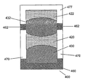
도 6은 4개의 개별적인 유체들(420, 430, 422, 432)을 포함하는 전기습윤장치(400)의 일례를 나타낸 것이다. 각각의 유체 용적은 인접한 유체와 혼합되지 않는다. 더구나, 각각의 유체 용적은, (대응하는 영역에 인접한 연속적인 영역들 중 어느 한 개의 영역보다는) 이 유체 용적이 선호하여 부착되는 각각의 영역과 접촉하고 있다. 예를 들면, 유체 용적 432는 인접한 영역들 477, 470보다는, 환형 내부 표면 영역 462에 부착하는 것을 선호한다. 마찬가지로, 유체 430은 (유체 420에 대응하는) 인접한 영역 470보다는 영역 460에 부착하는 것을 선호한다.6 shows an example of an
간략을 기하기 위해, 도 5에 예시된 전기습윤장치(300) 또는 도 6에 예시된 전기습윤장치(400)에 대해서는 전극을 도시하지 않았다.For simplicity, no electrodes are shown for the
전술한 실시예들은 단지 예를 들기 위해 주어진 것이라는 점은 자명하다.It is obvious that the above-described embodiments are given for illustrative purposes only.
서로 다른 젖음성을 갖는 영역들은 전체가 소수성 또는 친수성 재료로 형성될 수 있다는 것은 자명하다. 이와 달리, 이들 영역은 소수성 또는 친수성 물질을 사용하여 다른 재료를 코팅하여, 예를 들면, 침지 코팅 또는 화학기상증착에 의해 형성될 수도 있다.It is apparent that the regions having different wettability may be formed entirely of hydrophobic or hydrophilic materials. Alternatively, these regions may be formed by coating other materials with hydrophobic or hydrophilic materials, for example by dip coating or chemical vapor deposition.
이들 장치는 다중유체 충전 장치일 수 있으며, 전기습윤 현상을 이용하여 동작하는 장치에 한정되는 것은 아니다.These devices may be multifluid filling devices, and are not limited to devices operating using electrowetting phenomena.
이들 장치는 임의의 원하는 형상을 가질 수 있다. 예를 들면, 본 발명에 따른 전기습윤장치는 WO 00/58763에 기재된 것과 같은 형상을 가질 수도 있다.These devices can have any desired shape. For example, the electrowetting device according to the invention may have a shape as described in WO 00/58763.
상기 장치들은 광학 장치이거나, 광학 장치의 일부를 형성하거나, 다른 형태의 장치일 수도 있다.The devices may be optical devices, form part of the optical devices, or may be other types of devices.
도 7은 본 발명의 일 실시예에 따른 가변초점 렌즈를 포함하는 대물렌즈계 렌즈(18)를 구비한 광 기록매체(2) 주사장치(1)에 관한 것이다. 이 특정한 실시예에서는, 가변초점 렌즈(18)가 도 4에 예시된 전기습윤장치(200)에 해당한다. 그러 나, 다른 실시예들은 다른 유체 충전 장치들을 사용하여 원하는 광학 기능을 수행할 수도 있다는 것은 자명하다. 예를 들면, 조정가능한 강도를 갖는 렌즈로서, 또는 조정가능한 조리개로서, 또는 (예를 들면, 부재를 통과하는 방사빔에 조정가능한 양의 광학수차를 도입하기 위한) 파면 교정부재로서 적절한 장치가 주사장치에 사용될 수도 있다.FIG. 7 relates to an optical recording medium (2) scanning device (1) having an objective lens (18) including a variable focus lens in accordance with one embodiment of the present invention. In this particular embodiment, the
도 7은 대물렌즈(18)를 구비한 광 기록매체(2) 주사장치(1)를 나타낸 것이다. 기록매체는 투명층(3)을 구비하고, 이 투명층의 일면에는 정보층(4)이 배치된다. 투명층의 반대쪽에 있는 정보층의 면은 보호층(5)에 의해 외부의 영향으로부터 보호된다. 장치에 대향하는 투명층의 면은 입사면(6)으로 불린다. 투명층(3)은 정보층에 대한 기계적 지지를 제공함으로써 기록매체에 대한 기판으로서의 역할을 한다.7 shows an optical recording medium 2
이와 달리, 투명층은 정보층을 보호하는 유일한 기능을 갖는 한편, 기계적인 지지가 정보층의 다른 면에 있는 층, 예를 들면, 보호층(5)이나 정보층(4)에 연결된 또 다른 정보층과 투명층에 의해 제공될 수도 있다.In contrast, the transparent layer has a unique function of protecting the information layer, while the mechanical support is on a layer on the other side of the information layer, for example another layer connected to the
정보는, 도면에 도시되지 않은 대체로 평행하거나, 동심원을 이루거나 나선형의 트랙으로 배치된 광 검출가능한 마크들의 형태로 기록매체의 정보층(4)에 저장될 수 있다. 마크들은, 광학적으로 판독가능한 형태, 예를 들면, 피트들이 형태, 또는 그들의 주변부와 다른 반사계수 또는 자화방향을 갖는 영역들의 형태, 또는 이들 형태들의 조합을 가질 수도 있다.The information can be stored in the
주사장치(1)는, 방사빔(12)을 방출할 수 있는 방사원(11)을 구비한다. 방사 원은 반도체 레이저일 수 있다. 빔 스플리터(13)는 발산하는 방사빔(12)을 시준렌즈(14)를 향해 반사시키고, 이 시준렌즈는 발산 빔(12)을 시준된 빔(15)으로 변환한다. 평행광으로 변환된 빔(15)은 대물계(18)에 입사한다.The
대물계는 1개 이상의 렌즈 및/또는 격자를 포함할 수 있다. 대물계(18)는 광축(19)을 갖는다. 대물계(18)는 빔(17)을 기록매체(2)의 입사면(6)에 입사하는 수렴 빔(20)으로 변경한다. 대물계는, 투명층(30의 두께를 통해 방사빔을 통과시키도록 변형된 구면수차 교정값을 갖는다. 수렴 빔(20)은 정보층(4)에 스폿(21)을 형성한다. 정보층(4)에 의해 반사된 방사빔은 발산 빔(22)을 형성하며, 이것은 대물계(18)에 의해 거의 평행광으로 변환된 빔(23)으로 변환되고. 시준렌즈(14)에 의해 수렴 빔(24)으로 변환된다. 빔 스플리터(13)는 수렴 빔(24)의 적어도 일부를 검출계(25)를 향해 투과시킴으로써 전방 빔과 반사 빔을 분리한다. 검출계는 방사빔을 포착하여, 이 방사빔을 전기 출력신호(26). 신호처리기(27)는 이들 출력신호를 다양한 다른 신호로 변환한다.The objective system may include one or more lenses and / or gratings. The
이들 신호 중에서 한가지는 정보신호(28)로서, 이 신호의 값은 정보층(4)에서 판독된 정보를 표시한다. 정보신호는 오류정정용 정보처리부(29)에 의해 처리된다. 신호 처리기(27)로부터 발생된 나머지 신호들은 포커스 에러신호와 래디얼 에러신호(30)이다. 포커스 에러신호는 스폿(21)과 정보층(4) 사이의 축방향 높이차를 나타낸다. 래디얼 에러신호는 정보층(4)의 평면에서의 스폿(21)과 이 스폿이 따르는 정보층 내부의 트랙의 중심 사이의 거리를 표시한다. 포커스 에러신호와 래디얼 에러신호는 서보회로(31)에 공급되고, 이 서보회로는 이들 신호를 포커스 액추에이 터와 래디얼 액추에이터를 각각 제어하는 서보 제어신호들(32)로 변환한다. 액추에이터들은 도면에 나타내지 않았다. 포커스 액추에이터는 대물계(28)의 위치를 초점 방향(33)으로 제어함으로써. 스폿(21)의 실제 위치가 정보층(4)의 평면과 거의 일치하도록 이 실제 위치를 제어한다. 래디얼 액추에이터는 대물렌즈(18)의 위치를 반경방향(34)으로 제어함으로써, 스폿의 반경방향의 위치가 정보층(4) 내부에서 뒤따르는 트랙의 중심과 거의 일치하도록 이 반경방향의 위치를 제어한다. 도면에서 트랙들은 도면의 평면에 수직한 방향으로 진행한다.One of these signals is an
본 특정한 실시예에서 도 7의 장치는 기록매체(2)보다 두꺼운 투명층을 갖는 제 2 형태의 기록매체도 주사하도록 구성된다. 이 장치는, 제 2 형태의 기록매체를 주사하기 위해, 방사빔(12) 또는 이와 다른 파장을 갖는 방사빔을 사용할 수 있다. 이 방사빔의 NA는 기록매체의 형태에 맞추어 변형될 수도 있다. 대물계의 구면수차 보상이 이에 따라 변형될 수도 있다.In this particular embodiment, the apparatus of FIG. 7 is configured to scan a second type of recording medium having a transparent layer thicker than the recording medium 2. The apparatus may use a
전술한 것과 같은 내부 표면을 갖는 장치를 설치함으로써, 장치의 내부 표면의 부정확한 부분에 유체의 용적이 부착될 가능성이 크게 감소한다. 그 결과, 장치의 안정성이 향상된다. 이것은, 이 장치가 휴대형 CD(Compact Disc)나 DVD(Digital Versatile Disc) 플레이어 등의 휴대형 장치에 사용되는 경우에 특히 유리하다.By installing a device having an inner surface as described above, the possibility of a volume of fluid attached to an incorrect portion of the inner surface of the device is greatly reduced. As a result, the stability of the device is improved. This is particularly advantageous when the device is used in a portable device such as a portable CD (Compact Disc) or DVD (Digital Versatile Disc) player.
Claims (11)
Applications Claiming Priority (3)
| Application Number | Priority Date | Filing Date | Title |
|---|---|---|---|
| EP03075556.5 | 2003-02-25 | ||
| EP03075556 | 2003-02-25 | ||
| PCT/IB2004/050133 WO2004077125A2 (en) | 2003-02-25 | 2004-02-19 | Improvements in and relating to fluid filled devices |
Publications (2)
| Publication Number | Publication Date |
|---|---|
| KR20050122203A KR20050122203A (en) | 2005-12-28 |
| KR101154358B1 true KR101154358B1 (en) | 2012-06-15 |
Family
ID=32921590
Family Applications (1)
| Application Number | Title | Priority Date | Filing Date |
|---|---|---|---|
| KR1020057015620A Expired - Lifetime KR101154358B1 (en) | 2003-02-25 | 2004-02-19 | Improvements in and relating to fluid filled devices |
Country Status (7)
| Country | Link |
|---|---|
| US (1) | US7616737B2 (en) |
| EP (1) | EP1625437B1 (en) |
| JP (1) | JP4388954B2 (en) |
| KR (1) | KR101154358B1 (en) |
| CN (2) | CN1754112A (en) |
| TW (1) | TWI349112B (en) |
| WO (1) | WO2004077125A2 (en) |
Families Citing this family (44)
| Publication number | Priority date | Publication date | Assignee | Title |
|---|---|---|---|---|
| US7002666B2 (en) * | 2004-04-16 | 2006-02-21 | Asml Netherlands B.V. | Lithographic apparatus and device manufacturing method |
| FR2874707B1 (en) * | 2004-08-27 | 2006-11-17 | Varioptic Sa | VARIABLE FOCAL LENS |
| JP2006126740A (en) * | 2004-11-01 | 2006-05-18 | Fujinon Corp | Photographic optical system having focus function |
| EP1831884B1 (en) * | 2004-12-21 | 2008-04-30 | Koninklijke Philips Electronics N.V. | Optical scanning device |
| EP1851579A2 (en) * | 2004-12-21 | 2007-11-07 | Koninklijke Philips Electronics N.V. | Light distribution |
| WO2006070329A2 (en) * | 2004-12-29 | 2006-07-06 | Koninklijke Philips Electronics N.V. | Dual layer readout with improved tolerances |
| JP2008534997A (en) | 2005-03-24 | 2008-08-28 | コーニンクレッカ フィリップス エレクトロニクス エヌ ヴィ | Optical scanning device |
| FR2883987B1 (en) * | 2005-03-31 | 2008-02-01 | Varioptic Sa | OPTICAL SYSTEM FOR IMAGING POWER-ADJUSTING IMAGE |
| WO2006131882A1 (en) * | 2005-06-10 | 2006-12-14 | Koninklijke Philips Electronics N.V. | Variable fluid lens having two menisci |
| FR2887638B1 (en) | 2005-06-23 | 2007-08-31 | Varioptic Sa | VARIABLE FOCAL LENS WITH REDUCED INTERNAL PRESSURE VARIATION |
| FR2891372A1 (en) * | 2005-09-23 | 2007-03-30 | St Microelectronics Sa | VARIABLE FOCAL LENS BARREL |
| KR100723244B1 (en) * | 2005-12-27 | 2007-05-29 | 삼성전기주식회사 | Method for manufacturing liquid lens using electrowetting and liquid lens thereby |
| KR100759510B1 (en) * | 2006-03-08 | 2007-09-18 | 삼성전기주식회사 | Liquid lens |
| EP1884805A1 (en) * | 2006-08-01 | 2008-02-06 | Varioptic | Liquid lens with four liquids |
| US7324287B1 (en) * | 2006-11-07 | 2008-01-29 | Corning Incorporated | Multi-fluid lenses and optical devices incorporating the same |
| JP2010079096A (en) * | 2008-09-26 | 2010-04-08 | Sony Corp | Optical element and imaging apparatus |
| KR101675130B1 (en) * | 2009-09-03 | 2016-11-10 | 삼성전자주식회사 | Fluidic lens |
| US8743467B2 (en) | 2010-06-29 | 2014-06-03 | Johnson & Johnson Vision Care, Inc. | Lens with conical frustum meniscus wall |
| US9182521B2 (en) | 2010-05-14 | 2015-11-10 | Johnson & Johnson Vision Care, Inc. | Liquid meniscus lens including variable voltage zones |
| US8665526B2 (en) | 2010-05-14 | 2014-03-04 | Johnson & Johnson Vision Care, Inc. | Arcuate liquid meniscus lens |
| AU2015201128B2 (en) * | 2010-06-29 | 2016-08-04 | Johnson & Johnson Vision Care, Inc. | Lens with conical frustum meniscus wall |
| US8638501B2 (en) | 2010-07-27 | 2014-01-28 | Johnson & Johnson Vision Care, Inc. | Liquid meniscus lens with convex torus-segment meniscus wall |
| US8634145B2 (en) | 2010-07-29 | 2014-01-21 | Johnson & Johnson Vision Care, Inc. | Liquid meniscus lens with concave torus-segment meniscus wall |
| US8767308B2 (en) | 2010-08-23 | 2014-07-01 | Johnson & Johnson Vision Care, Inc | Negative add liquid meniscus lens |
| US8693104B2 (en) | 2010-08-24 | 2014-04-08 | Johnson & Johnson Vision Care, Inc. | Lens with compound linear-convex meniscus wall |
| US8767309B2 (en) | 2010-09-08 | 2014-07-01 | Johnson & Johnson Vision Care, Inc. | Lens with multi-convex meniscus wall |
| US20120092774A1 (en) | 2010-09-27 | 2012-04-19 | Pugh Randall B | Lens with multi-segmented linear meniscus wall |
| CN103124920B (en) | 2010-09-27 | 2016-04-20 | 庄臣及庄臣视力保护公司 | Comprise the fluid meniscus lens of graded thickness dielectric coating |
| US8638502B2 (en) | 2010-09-29 | 2014-01-28 | Johnson & Johnson Vision Care, Inc. | Liquid meniscus lens with non-spherical meniscus wall |
| US8687280B2 (en) | 2010-09-29 | 2014-04-01 | Johnson & Johnson Vision Care, Inc. | Liquid meniscus lens including meniscus wall with microchannels |
| NL2007425A (en) | 2010-11-12 | 2012-05-15 | Asml Netherlands Bv | Metrology method and apparatus, and device manufacturing method. |
| WO2012062858A1 (en) | 2010-11-12 | 2012-05-18 | Asml Netherlands B.V. | Metrology method and apparatus, lithographic system and device manufacturing method |
| US8867141B2 (en) | 2011-03-18 | 2014-10-21 | Johnson & Johnson Vision Care, Inc. | Lens with multi-concave meniscus wall |
| US9813695B2 (en) | 2011-11-09 | 2017-11-07 | Koninklijke Philips N.V. | Display device with free focus capability |
| US9615812B2 (en) | 2013-06-19 | 2017-04-11 | Koninklijke Philips N.V. | Calibration of imagers with dynamic beam shapers |
| DE102014205790A1 (en) * | 2014-03-27 | 2015-10-01 | Albert-Ludwigs-Universität Freiburg | Optofluidic component |
| US10466468B2 (en) | 2014-12-31 | 2019-11-05 | Corning Incorporated | Method to separate an emulsion in a liquid lens |
| CN105137593B (en) * | 2015-10-27 | 2017-12-08 | 中国工程物理研究院激光聚变研究中心 | A kind of wave-front corrector and its bearing calibration |
| EP3281598A1 (en) | 2016-08-09 | 2018-02-14 | Koninklijke Philips N.V. | Light based skin treatment device and method |
| TWI781985B (en) | 2017-03-09 | 2022-11-01 | 美商康寧公司 | Camera modules with autofocus and optical image stabilization functions |
| CN107166295B (en) * | 2017-07-27 | 2019-11-29 | 温岭市海奔光电科技股份有限公司 | Liquid variant distance-light switching system |
| WO2019028207A1 (en) | 2017-08-02 | 2019-02-07 | Corning Incorporated | Flexible subtrate and circuit for liquid lens system |
| US11191636B2 (en) * | 2017-08-22 | 2021-12-07 | Verily Life Sciences Llc | Electrowetting lenses having oleophobic surfaces |
| CN111257980B (en) * | 2018-12-03 | 2022-05-17 | 宁波舜宇光电信息有限公司 | Optical filtering device, optical lens and assembling method thereof |
Citations (3)
| Publication number | Priority date | Publication date | Assignee | Title |
|---|---|---|---|---|
| US4079368A (en) * | 1976-05-17 | 1978-03-14 | International Business Machines Corporation | Information display through deformation of liquid dielectric media |
| WO2002069016A2 (en) * | 2001-02-28 | 2002-09-06 | Lightwave Microsystems Corporation | Microfluid control for waveguide optical switches, variable attenuators, and other optical devices |
| EP1069450B1 (en) * | 1999-06-16 | 2010-01-13 | Canon Kabushiki Kaisha | Electrowetting optical element |
Family Cites Families (8)
| Publication number | Priority date | Publication date | Assignee | Title |
|---|---|---|---|---|
| FR2524658A1 (en) * | 1982-03-30 | 1983-10-07 | Socapex | OPTICAL SWITCH AND SWITCHING MATRIX COMPRISING SUCH SWITCHES |
| US5956005A (en) * | 1995-12-29 | 1999-09-21 | Xerox Corporation | Electrocapillary display sheet which utilizes an applied electric field to move a liquid inside the display sheet |
| US5659330A (en) * | 1996-05-31 | 1997-08-19 | Xerox Corporation | Electrocapillary color display sheet |
| FR2769375B1 (en) * | 1997-10-08 | 2001-01-19 | Univ Joseph Fourier | VARIABLE FOCAL LENS |
| US6702483B2 (en) | 2000-02-17 | 2004-03-09 | Canon Kabushiki Kaisha | Optical element |
| JP4521920B2 (en) | 2000-03-03 | 2010-08-11 | キヤノン株式会社 | Capacitance detection device for optical element and optical device provided with capacitance detection device |
| EP1336181A2 (en) | 2000-11-09 | 2003-08-20 | Koninklijke Philips Electronics N.V. | Multi-fluid elements device with controllable fluid level by means of matrix addressing |
| WO2004099844A1 (en) * | 2003-05-06 | 2004-11-18 | Koninklijke Philips Electronics N.V. | Electrowetting module |
-
2004
- 2004-02-19 KR KR1020057015620A patent/KR101154358B1/en not_active Expired - Lifetime
- 2004-02-19 EP EP04712641.2A patent/EP1625437B1/en not_active Expired - Lifetime
- 2004-02-19 US US10/546,394 patent/US7616737B2/en active Active
- 2004-02-19 WO PCT/IB2004/050133 patent/WO2004077125A2/en not_active Ceased
- 2004-02-19 CN CNA2004800050486A patent/CN1754112A/en active Pending
- 2004-02-19 CN CN2004800050378A patent/CN1871538B/en not_active Expired - Lifetime
- 2004-02-19 JP JP2006502605A patent/JP4388954B2/en not_active Expired - Lifetime
- 2004-02-20 TW TW093104337A patent/TWI349112B/en not_active IP Right Cessation
Patent Citations (3)
| Publication number | Priority date | Publication date | Assignee | Title |
|---|---|---|---|---|
| US4079368A (en) * | 1976-05-17 | 1978-03-14 | International Business Machines Corporation | Information display through deformation of liquid dielectric media |
| EP1069450B1 (en) * | 1999-06-16 | 2010-01-13 | Canon Kabushiki Kaisha | Electrowetting optical element |
| WO2002069016A2 (en) * | 2001-02-28 | 2002-09-06 | Lightwave Microsystems Corporation | Microfluid control for waveguide optical switches, variable attenuators, and other optical devices |
Also Published As
| Publication number | Publication date |
|---|---|
| WO2004077125A3 (en) | 2006-07-20 |
| EP1625437B1 (en) | 2013-07-03 |
| TW200424557A (en) | 2004-11-16 |
| CN1871538A (en) | 2006-11-29 |
| KR20050122203A (en) | 2005-12-28 |
| JP4388954B2 (en) | 2009-12-24 |
| CN1754112A (en) | 2006-03-29 |
| JP2007528008A (en) | 2007-10-04 |
| EP1625437A2 (en) | 2006-02-15 |
| WO2004077125A2 (en) | 2004-09-10 |
| CN1871538B (en) | 2010-05-12 |
| US7616737B2 (en) | 2009-11-10 |
| TWI349112B (en) | 2011-09-21 |
| US20060245092A1 (en) | 2006-11-02 |
Similar Documents
| Publication | Publication Date | Title |
|---|---|---|
| KR101154358B1 (en) | Improvements in and relating to fluid filled devices | |
| EP1625442B1 (en) | Variable shape lens | |
| EP1625441B1 (en) | Variable lens | |
| US7724444B2 (en) | Optical element, optical device, atmosphere provider, optical scanning device, light coupling device, and method of operating interfacial waves | |
| US20060158971A1 (en) | Objective lens for optical disk recording/reproducing device comprising variable lens formed by the interface of two immiscible fluids | |
| TWI382409B (en) | Optical component for introducing optical aberrations into a beam | |
| US7342725B2 (en) | Variable refractive surface |
Legal Events
| Date | Code | Title | Description |
|---|---|---|---|
| PA0105 | International application |
Patent event date: 20050824 Patent event code: PA01051R01D Comment text: International Patent Application |
|
| PG1501 | Laying open of application | ||
| A201 | Request for examination | ||
| PA0201 | Request for examination |
Patent event code: PA02012R01D Patent event date: 20090219 Comment text: Request for Examination of Application |
|
| E902 | Notification of reason for refusal | ||
| PE0902 | Notice of grounds for rejection |
Comment text: Notification of reason for refusal Patent event date: 20101125 Patent event code: PE09021S01D |
|
| E90F | Notification of reason for final refusal | ||
| PE0902 | Notice of grounds for rejection |
Comment text: Final Notice of Reason for Refusal Patent event date: 20110830 Patent event code: PE09021S02D |
|
| E701 | Decision to grant or registration of patent right | ||
| PE0701 | Decision of registration |
Patent event code: PE07011S01D Comment text: Decision to Grant Registration Patent event date: 20120309 |
|
| GRNT | Written decision to grant | ||
| PR0701 | Registration of establishment |
Comment text: Registration of Establishment Patent event date: 20120601 Patent event code: PR07011E01D |
|
| PR1002 | Payment of registration fee |
Payment date: 20120604 End annual number: 3 Start annual number: 1 |
|
| PG1601 | Publication of registration | ||
| FPAY | Annual fee payment |
Payment date: 20150526 Year of fee payment: 4 |
|
| PR1001 | Payment of annual fee |
Payment date: 20150526 Start annual number: 4 End annual number: 4 |
|
| FPAY | Annual fee payment |
Payment date: 20160523 Year of fee payment: 5 |
|
| PR1001 | Payment of annual fee |
Payment date: 20160523 Start annual number: 5 End annual number: 5 |
|
| FPAY | Annual fee payment |
Payment date: 20170523 Year of fee payment: 6 |
|
| PR1001 | Payment of annual fee |
Payment date: 20170523 Start annual number: 6 End annual number: 6 |
|
| FPAY | Annual fee payment |
Payment date: 20180531 Year of fee payment: 7 |
|
| PR1001 | Payment of annual fee |
Payment date: 20180531 Start annual number: 7 End annual number: 7 |
|
| FPAY | Annual fee payment |
Payment date: 20190603 Year of fee payment: 8 |
|
| PR1001 | Payment of annual fee |
Payment date: 20190603 Start annual number: 8 End annual number: 8 |
|
| PR1001 | Payment of annual fee |
Payment date: 20200527 Start annual number: 9 End annual number: 9 |
|
| PR1001 | Payment of annual fee |
Payment date: 20210524 Start annual number: 10 End annual number: 10 |
|
| PR1001 | Payment of annual fee |
Payment date: 20230522 Start annual number: 12 End annual number: 12 |
|
| PC1801 | Expiration of term |
Termination date: 20240819 Termination category: Expiration of duration |