KR101150005B1 - Ultrasound apparatus and method for setting intima-media thickness measurement area - Google Patents
Ultrasound apparatus and method for setting intima-media thickness measurement area Download PDFInfo
- Publication number
- KR101150005B1 KR101150005B1 KR1020080115332A KR20080115332A KR101150005B1 KR 101150005 B1 KR101150005 B1 KR 101150005B1 KR 1020080115332 A KR1020080115332 A KR 1020080115332A KR 20080115332 A KR20080115332 A KR 20080115332A KR 101150005 B1 KR101150005 B1 KR 101150005B1
- Authority
- KR
- South Korea
- Prior art keywords
- graph
- average value
- moving average
- thickness
- measurement area
- Prior art date
- Legal status (The legal status is an assumption and is not a legal conclusion. Google has not performed a legal analysis and makes no representation as to the accuracy of the status listed.)
- Active
Links
Images


Classifications
-
- A—HUMAN NECESSITIES
- A61—MEDICAL OR VETERINARY SCIENCE; HYGIENE
- A61B—DIAGNOSIS; SURGERY; IDENTIFICATION
- A61B8/00—Diagnosis using ultrasonic, sonic or infrasonic waves
- A61B8/13—Tomography
- A61B8/14—Echo-tomography
-
- A—HUMAN NECESSITIES
- A61—MEDICAL OR VETERINARY SCIENCE; HYGIENE
- A61B—DIAGNOSIS; SURGERY; IDENTIFICATION
- A61B8/00—Diagnosis using ultrasonic, sonic or infrasonic waves
- A61B8/08—Clinical applications
- A61B8/0858—Clinical applications involving measuring tissue layers, e.g. skin, interfaces
-
- A—HUMAN NECESSITIES
- A61—MEDICAL OR VETERINARY SCIENCE; HYGIENE
- A61B—DIAGNOSIS; SURGERY; IDENTIFICATION
- A61B5/00—Measuring for diagnostic purposes; Identification of persons
- A61B5/02—Detecting, measuring or recording for evaluating the cardiovascular system, e.g. pulse, heart rate, blood pressure or blood flow
- A61B5/02007—Evaluating blood vessel condition, e.g. elasticity, compliance
-
- G—PHYSICS
- G06—COMPUTING OR CALCULATING; COUNTING
- G06T—IMAGE DATA PROCESSING OR GENERATION, IN GENERAL
- G06T7/00—Image analysis
- G06T7/0002—Inspection of images, e.g. flaw detection
- G06T7/0012—Biomedical image inspection
-
- G—PHYSICS
- G06—COMPUTING OR CALCULATING; COUNTING
- G06T—IMAGE DATA PROCESSING OR GENERATION, IN GENERAL
- G06T7/00—Image analysis
- G06T7/60—Analysis of geometric attributes
- G06T7/62—Analysis of geometric attributes of area, perimeter, diameter or volume
-
- G—PHYSICS
- G06—COMPUTING OR CALCULATING; COUNTING
- G06T—IMAGE DATA PROCESSING OR GENERATION, IN GENERAL
- G06T2207/00—Indexing scheme for image analysis or image enhancement
- G06T2207/10—Image acquisition modality
- G06T2207/10132—Ultrasound image
-
- G—PHYSICS
- G06—COMPUTING OR CALCULATING; COUNTING
- G06T—IMAGE DATA PROCESSING OR GENERATION, IN GENERAL
- G06T2207/00—Indexing scheme for image analysis or image enhancement
- G06T2207/30—Subject of image; Context of image processing
- G06T2207/30004—Biomedical image processing
- G06T2207/30101—Blood vessel; Artery; Vein; Vascular
Landscapes
- Health & Medical Sciences (AREA)
- Engineering & Computer Science (AREA)
- Life Sciences & Earth Sciences (AREA)
- Physics & Mathematics (AREA)
- General Health & Medical Sciences (AREA)
- Medical Informatics (AREA)
- Surgery (AREA)
- Public Health (AREA)
- Biomedical Technology (AREA)
- Heart & Thoracic Surgery (AREA)
- Pathology (AREA)
- Molecular Biology (AREA)
- Nuclear Medicine, Radiotherapy & Molecular Imaging (AREA)
- Animal Behavior & Ethology (AREA)
- Biophysics (AREA)
- Radiology & Medical Imaging (AREA)
- Veterinary Medicine (AREA)
- Computer Vision & Pattern Recognition (AREA)
- General Physics & Mathematics (AREA)
- Theoretical Computer Science (AREA)
- Quality & Reliability (AREA)
- Vascular Medicine (AREA)
- Cardiology (AREA)
- Physiology (AREA)
- Geometry (AREA)
- Ultra Sonic Daignosis Equipment (AREA)
Abstract
본 발명은 IMT(Intima-Media Thickness) 측정 영역을 설정하는 초음파 장치 및 방법에 관한 것이다. 이 IMT 측정 영역 설정 초음파 장치 및 방법은. 초음파 신호를 대상체에 송신하고 상기 대상체로부터 반사되는 초음파 에코신호를 수신하여 상기 대상체의 초음파 영상 - 상기 초음파 영상은 그레이 레벨의 세기(intensity) 값을 갖는 다수의 픽셀을 포함함 - 을 형성하며 상기 초음파 영상을 이용하여 상기 다수의 픽셀들의 세기에 해당하는 제1 그래프를 형성하고, 상기 제1 그래프를 이용하여 혈관의 두께에 해당하는 제1 이동 평균값을 산출하여 제2 그래프를 형성하고, 혈관벽의 두께에 해당하는 제2 이동 평균값을 산출하여 제3 그래프를 형성하며, 상기 제2 그래프 및 상기 제3 그래프를 이용하여 상기 초음파 영상에 IMT(Intima-Media Thickness) 측정 영역을 설정하도록 동작한다. The present invention relates to an ultrasonic apparatus and method for setting an IMT (Intima-Media Thickness) measurement area. This IMT measurement area setting ultrasonic device and method. Transmitting an ultrasound signal to an object and receiving an ultrasound echo signal reflected from the object to form an ultrasound image of the object, wherein the ultrasound image includes a plurality of pixels having intensity values of gray levels. Using the image to form a first graph corresponding to the intensity of the plurality of pixels, using the first graph to calculate a first moving average value corresponding to the thickness of the vessel to form a second graph, the thickness of the vessel wall Calculates a second moving average value corresponding to the second graph to form a third graph, and sets an IMT (Intima-Media Thickness) measurement region in the ultrasound image by using the second graph and the third graph.
초음파 장치, IMT, 측정 영역 설정Ultrasonic Device, IMT, Measurement Area Setup
Description
본 발명은 초음파 장치 및 방법에 관한 것으로, 특히 IMT(Intima-Media Thickness) 측정 영역을 설정하는 방법 및 초음파 장치에 관한 것이다.BACKGROUND OF THE
일반적으로, 초음파 장치는 피검체의 체표로부터 체내의 소망 부위를 향하여 초음파 신호를 조사하고, 반사된 초음파 신호(초음파 에코신호)의 정보를 이용하여 연부조직의 단층이나 혈류에 관한 이미지를 무침습으로 얻는 장치이다. 이 장치는 X선 진단장치, X선 CT 스캐너(Computerized Tomography Scanner), MRI(Magnetic Resonance Image), 핵의학 진단장치 등의 다른 화상 진단장치와 비교할 때, 소형이고 저렴하며, 실시간으로 표시 가능하고, X선 등의 피폭이 없어 안전성이 높은 장점을 갖고 있어, 심장, 복부, 비뇨기, 산부인과 및 혈관 진단을 위해 널리 이용되고 있다.In general, an ultrasound apparatus irradiates an ultrasonic signal from a body surface of a subject to a desired part of the body, and uses the information of the reflected ultrasonic signal (ultrasound echo signal) to make an image of soft tissue tomography or blood flow non-invasive. It is a device to get. Compared with other imaging devices such as X-ray diagnostics, X-ray CT scanners, magnetic resonance images, nuclear medicine diagnostics, etc. Since there is no exposure to X-rays and the like, it has a high safety advantage and is widely used for diagnosing the heart, abdomen, urinary gynecology and vascular.
인체에 있는 다수의 혈관 중 경동맥은 심장에서 나온 대동맥과 뇌혈관을 잇는 혈관으로 목 왼쪽과 오른쪽에 2개가 있다. 뇌로 가는 혈액의 80% 정도가 경동맥을 통과하게 된다. 초음파 장치를 이용한 경동맥 검사는 경동맥의 막히고 딱딱해진 정도를 정확하게 평가할 수 있는 유용한 검사 방법이다. 경동맥의 동맥경화 정도를 나타내는 지표로서 IMT(intima-media thickness)가 이용되는데, IMT는 경동맥의 내막과 중막 사이의 두께를 의미한다.Among the many blood vessels in the human body, the carotid artery is a blood vessel connecting the aorta from the heart with the cerebrovascular vessels, two on the left and right sides of the neck. About 80% of the blood going to the brain passes through the carotid artery. Carotid artery examination using an ultrasound device is a useful test method that can accurately assess the degree of blockage and stiffness of the carotid artery. IMT (intima-media thickness) is used as an index indicating the degree of arteriosclerosis of the carotid artery.
IMT를 측정하기 위하여 작은 영역을 반복적으로 측정하여야 하기 때문에 상당히 오랜 시간과 노력을 요구한다. 이러한 IMT 측정을 쉽고 빠르게 하기 위하여 IMT를 자동으로 측정하는 어플리케이션(application)들이 개발 되어 있다. 하지만, 이러한 자동 IMT 측정 어플리케이션들에서도 측정 영역을 설정하는 것은 사용자에 의해서 수행되어야 하므로 IMT 측정시 부정확한 측정이 이루어지는 등의 문제점이 있다. In order to measure IMT, a small area needs to be measured repeatedly, which requires a long time and effort. In order to make the IMT measurement easy and fast, applications for automatically measuring the IMT have been developed. However, even in such automatic IMT measurement applications, setting the measurement area has to be performed by a user, and thus there is a problem that an incorrect measurement is made during IMT measurement.
본 발명은 IMT(Intima-Media Thickness) 측정 영역을 자동으로 설정하는 방법 및 초음파 장치에 관한 것이다.The present invention relates to a method and an ultrasonic apparatus for automatically setting an Intima-Media Thickness (IMT) measurement area.
본 발명의 초음파 장치는, 초음파 신호를 대상체에 송신하고 상기 대상체로부터 반사되는 초음파 에코신호를 수신하여 상기 대상체의 초음파 영상 - 상기 초음파 영상은 그레이 레벨의 세기(intensity) 값을 갖는 다수의 픽셀을 포함함 - 을 형성하는 초음파 진단부; 및 상기 초음파 영상을 이용하여 상기 다수의 픽셀들의 세기에 해당하는 제1 그래프를 형성하고, 상기 제1 그래프를 이용하여 혈관의 두께에 해당하는 제1 이동 평균값을 산출하여 제2 그래프를 형성하고, 혈관벽의 두께에 해당하는 제2 이동 평균값을 산출하여 제3 그래프를 형성하며, 상기 제2 그래프 및 상기 제3 그래프를 이용하여 상기 초음파 영상에 IMT(Intima-Media Thickness) 측정 영역을 설정하도록 동작하는 영상 처리부를 포함한다.The ultrasound apparatus of the present invention transmits an ultrasound signal to an object and receives an ultrasound echo signal reflected from the object so that the ultrasound image of the object, the ultrasound image includes a plurality of pixels having intensity values of gray levels. An ultrasound diagnostic unit forming a box; And forming a first graph corresponding to the intensity of the plurality of pixels by using the ultrasound image, calculating a first moving average value corresponding to the thickness of blood vessel using the first graph, and forming a second graph. Calculating a second moving average value corresponding to the thickness of the blood vessel wall to form a third graph, and setting an IMT (Intima-Media Thickness) measurement region on the ultrasound image by using the second graph and the third graph It includes an image processor.
또한, 본 발명의 IMT 측정 영역 설정 방법은, a) 초음파 신호를 대상체에 송신하고 상기 대상체로부터 반사되는 초음파 에코신호를 수신하여 상기 대상체의 초음파 영상을 형성하는 단계; b) 상기 초음파 영상을 이용하여 상기 다수의 픽셀들의 세기에 해당하는 제1 그래프를 형성하는 단계; c) 상기 제1 그래프를 이용하여 혈관의 두께에 해당하는 제1 이동 평균값을 산출하여 제2 그래프를 형성하는 단계; d) 상기 제1 그래프를 이용하여 혈관벽의 두께에 해당하는 제2 이동 평균값을 산출하여 제3 그래프를 형성하는 단계; 및 e) 상기 제2 그래프 및 상기 제3 그래프를 이용하여 상기 초음파 영상에 IMT 측정 영역을 설정하는 단계를 포함한다.The method of setting an IMT measurement region according to the present invention may include: a) transmitting an ultrasound signal to an object and receiving an ultrasound echo signal reflected from the object to form an ultrasound image of the object; b) forming a first graph corresponding to the intensity of the plurality of pixels by using the ultrasound image; c) forming a second graph by calculating a first moving average value corresponding to the thickness of the blood vessel using the first graph; d) calculating a second moving average value corresponding to the thickness of the blood vessel wall by using the first graph to form a third graph; And e) setting an IMT measurement area on the ultrasound image by using the second graph and the third graph.
본 발명에 의하면, 혈관의 IMT(Intima-Media Thickness) 측정시 오랜 시간과 노력이 요구되는 측정 영역 설정을 자동으로 수행할 수 있어, IMT 측정의 정확성과 신속성을 향상 시킬 수 있다.According to the present invention, it is possible to automatically set the measurement area that requires a long time and effort when measuring blood vessel IMT (Intima-Media Thickness), thereby improving the accuracy and speed of IMT measurement.
이하 첨부된 도면을 참조하여 본 발명의 다양한 실시예들에 대해 상세히 설명한다. Hereinafter, various embodiments of the present invention will be described in detail with reference to the accompanying drawings.
도 1은 본 발명의 실시예에 따른 초음파 장치(100)의 구성을 보이는 블록도이다. 초음파 진단부(110)는 초음파 신호를 대상체에 송신하고 대상체로부터 반사되는 초음파 신호(즉, 초음파 에코신호)를 수신하여 대상체의 초음파 영상을 형성한다.1 is a block diagram showing the configuration of an
도 2는 본 발명의 실시예에 따른 초음파 진단부(110)의 구성을 보이는 블록도이다. 초음파 진단부(110)는 송신신호 형성부(111), 적어도 하나의 변환소자(transducer element)를 포함하는 초음파 프로브(112), 빔 포머(113), 신호 처리부(114) 및 초음파 영상 형성부(115)를 포함한다.2 is a block diagram showing the configuration of the ultrasonic
송신신호 형성부(111)는 초음파 프로브(112)의 변환소자 위치 및 집속점을 고려하여, 프레임을 얻기 위한 송신신호를 형성한다. 본 실시예에서 프레임은 B-모드(brightness mode) 영상의 프레임을 포함한다.The transmission
초음파 프로브(112)는 컨벡스 프로브(convex probe), 선형 프로브(linear probe) 등으로 구현되어, 송신신호 형성부(111)로부터 제공되는 송신신호를 초음파 신호로 변환하여 대상체에 송신하고 대상체로부터 반사되는 초음파 에코신호를 수신하여 수신신호를 형성한다.The
빔 포머(113)는 초음파 프로브(112)로부터 제공되는 수신신호를 아날로그/디지털 변환한다. 아울러, 빔 포머(113)는 초음파 프로브(112)의 변환소자 위치 및 집속점을 고려하여 디지털 변환된 수신신호를 수신 집속시킨다.The beam former 113 analog-to-digital converts the received signal provided from the
신호 처리부(114)는 빔 포머(113)로부터 제공되는 수신 집속된 수신신호에 대해, 초음파 영상을 형성하는데 필요한 다양한 신호 처리(예를 들어, 게인(gain) 조절, TGC(time gain compensation) 조절 등)를 수행하여 초음파 데이터를 형성한다.The
초음파 영상 형성부(115)는 신호 처리부(114)로부터 제공되는 초음파 데이터를 이용하여 대상체의 초음파 영상을 형성한다. 일례로서, 초음파 영상은 도 3에 도시된 바와 같이 그레이 레벨(gray level)의 세기(intensity) 값을 갖는 다수의 픽셀(pixel)로 이루어진다.The ultrasound
다시 도 1을 참조하면, 영상 처리부(120)는 초음파 진단부(110)로부터 제공되는 초음파 영상을 분석하여 초음파 영상에 IMT(Intima-Media Thickness) 측정 영역을 설정한다.Referring back to FIG. 1, the
도 4는 본 발명의 실시예에 따른 영상 처리부(120)의 구성을 보이는 블록도이다. 영상 처리부(120)는 제1 그래프 형성부(121), 제2 그래프 형성부(122), 제3 그래프 형성부(123) 및 IMT 측정 영역 설정부(124)를 포함한다.4 is a block diagram illustrating a configuration of an
제1 그래프 형성부(121)는 초음파 진단부(110)로부터 제공되는 초음파 영상을 이용하여 픽셀들의 세기 평균값에 해당하는 그래프(이하, 제1 그래프라 함)를 형성한다. 본 실시예에서 제1 그래프 형성부(121)는 도 3에 도시된 바와 같은 초음파 영상에 대해 동일한 픽셀 행(가로 방향)에 존재하는 픽셀들의 세기 평균값을 산출한다. 이때, 세기 평균값(f)은 아래의 수학식을 이용하여 산출될 수 있다.The first
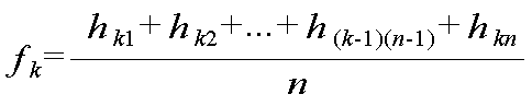
여기서, k는 도 3에 도시된 바와 같이 초음파 영상에서 픽셀 행을 나타내고, 1 내지 m의 값을 가지며, n은 동일한 픽셀 행에 존재하는 픽셀의 개수를 나타낸다.Here, k denotes a row of pixels in the ultrasound image, as shown in FIG. 3, and has a value of 1 to m, and n denotes the number of pixels existing in the same pixel row.
제1 그래프 형성부(121)는 산출된 세기 평균값을 이용하여 도 5에 도시된 바와 같이 산출된 세기 평균값을 가로축의 좌표값으로 나타내고, 픽셀 행(i=1~m)을 세로축의 좌표값으로 나타내는 제1 그래프를 형성한다.The first
제2 그래프 형성부(122)는 제1 그래프 형성부(121)에서 형성된 제1 그래프를 이용하여 평균 세기값들을 혈관의 두께에 해당하는 길이로 평균한 이동 평균값(이하, 제1 이동 평균값이라 함)을 산출한다. 여기서, 혈관의 두께는 2 내지 5mm 바람직하게 3mm이고, 픽셀의 크기(여기서 크기는 픽셀의 행, 즉 높이(height)를 나타냄)는 0.5mm인 것으로 한다. 본 실시예에서 제1 이동 평균값(MAv1 내지 MAvm)은 아래의 수학식을 이용하여 산출될 수 있다.The second


![]()
![]()
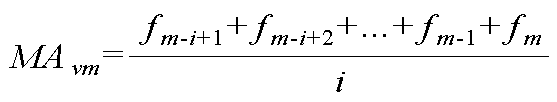
여기서, i는 혈관의 두께에 해당하는 픽셀 행, 즉 세기 평균값의 개수를 나타낸다. 일례로서, 혈관의 두께가 3mm이고 픽셀의 크기가 0.5m이면, i는 6이 된다. 또한, f는 세기 평균값을 나타낸다.Here, i denotes the number of pixel rows corresponding to the thickness of blood vessels, that is, the number of intensity average values. As an example, if the blood vessel thickness is 3 mm and the pixel size is 0.5 m, i is 6. In addition, f represents an intensity average value.
제2 그래프 형성부(122)는 도 6에 도시된 바와 같이 산출된 제1 이동 평균값을 가로축의 좌표값으로 나타내고, 픽셀 행을 가로축으로 나타내는 그래프(이하, 제2 그래프라 함)를 형성한다.The second
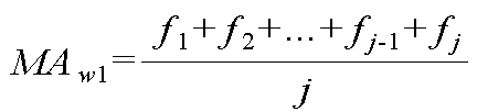
제3 그래프 형성부(123)는 제1 그래프 형성부(121)에서 형성된 제1 그래프를 이용하여 평균 세기값들을 혈관벽의 두께에 해당하는 길이로 평균한 이동 평균값(이하, 제2 이동 평균값이라 함)을 산출한다. 여기서, 혈관벽의 두께는 0.5 내지 1.5mm 바람직하게 1mm이다. 본 실시예에서 제2 이동 평균값(MAw1 내지 MAwm)은 아래의 수학식을 이용하여 산출될 수 있다.The third

![]()
![]()

여기서, j는 혈관벽의 두께에 해당하는 픽셀 행, 즉 세기 평균값의 개수를 나타낸다. 일례로서, 혈관벽의 두께가 1mm이고 픽셀의 크기가 0.5m이면, j는 2가 된다. 또한, f는 세기 평균값을 나타낸다.Here, j represents the number of pixel rows corresponding to the thickness of the vessel wall, that is, the intensity average value. As an example, j is 2 if the thickness of the vessel wall is 1 mm and the size of the pixel is 0.5 m. In addition, f represents an intensity average value.
제3 그래프 형성부(123)는 도 7에 도시된 바와 같이 산출된 제2 이동 평균값을 가로축의 좌표값으로 나타내고, 픽셀 행을 가로축으로 나타내는 그래프(이하, 제3 그래프라 함)를 형성한다.The third
IMT 측정 영역 설정부(124)는 제2 그래프 형성부(122)에서 형성된 제2 그래프와 제3 그래프 형성부(123)에서 형성된 제3 그래프를 이용하여 변곡점을 검출하고, 검출된 변곡점을 IMT(Intima-Media Thickness) 측정 영역으로 초음파 영상에 설정한다. 본 실시예에서 IMT 측정 영역 설정부(124)는 제2 그래프 형성부(122)에서 형성된 제2 그래프에서 기울기가 변하는 다수의 변곡점을 검출하고, 검출된 다수의 변곡점에서 도 6에 도시된 바와 같이 가장 작은 값을 갖는 변곡점(Il)을 검출한다. IMT 측정 영역 설정부(124)는 제3 그래프 형성부(123)에서 형성된 제3 그래프에서 기울기가 변하는 다수의 변곡점을 검출하고, 검출된 다수의 변곡점에서 가장 큰 값을 갖는 변곡점(Im)을 검출한다. IMT 측정 영역 설정부(124)는 검출된 변곡점(Il)과 변곡점(Im) 사이를 IMT(Intima-Media Thickness) 측정 영역으로서 초음파 영상에 설정한다.The IMT measurement
다시 도 1을 참조하면, 디스플레이부(130)는 영상 처리부(120)에 의해 IMT 측정 영역이 설정된 초음파 영상을 디스플레이한다.Referring back to FIG. 1, the
제어부(140)는 초음파 진단부(110)의 초음파 영상 형성을 제어한다. 아울러 제어부(140)는 제1 내지 제3 그래프의 형성을 제어하고, IMT 측정 영역의 설정을 제어한다.The
본 발명이 속하는 기술분야의 당업자는 본 발명이 그 기술적 사상이나 필수적인 특징을 설정하지 않고서 다른 구체적인 형태로 실시될 수 있다는 것을 이해할 수 있을 것이다. 그러므로 이상에서 기술한 실시 예들은 모든 면에서 예시적인 것이며 한정적이 아닌 것으로 이해해야만 한다. 본 발명의 범위는 상기 상세한 설명보다는 후술하는 특허청구범위에 의하여 나타내어지며, 특허청구범위의 의미 및 범위 그리고 그 등가 개념으로부터 도출되는 모든 설정 또는 변형된 형태가 본 발명의 범위에 포함되는 것으로 해석되어야 한다.Those skilled in the art to which the present invention pertains will understand that the present invention can be implemented in other specific forms without setting the technical spirit or essential features. It is therefore to be understood that the above-described embodiments are illustrative in all aspects and not restrictive. The scope of the present invention is shown by the following claims rather than the detailed description, and all settings or modifications derived from the meaning and scope of the claims and their equivalent concepts should be construed as being included in the scope of the present invention. do.
일례로서, 전술한 예에서는 동일한 행에 존재하는 픽셀들의 평균 세기값을 산출하고 산출된 평균 세기값을 가로축의 좌표값으로 나타내는 제1 그래프를 형성하는 것으로 설명하였지만, 다른 예에서는 동일한 행에 존재하는 픽셀들의 세기값을 가산한 가산 세기값을 산출하고, 산출된 가산 세기값을 가로축의 좌표값으로 나타내는 제1 그래프를 형성할 수도 있다.As an example, in the above-described example, the average intensity values of the pixels present in the same row are calculated and the first graph representing the calculated average intensity values in the coordinates of the abscissa is described. An addition intensity value obtained by adding the intensity values of the pixels may be calculated, and a first graph representing the calculated addition intensity value as a coordinate value on the horizontal axis may be formed.
도 1은 본 발명의 실시예에 따른 초음파 장치의 구성을 보이는 블록도.1 is a block diagram showing the configuration of an ultrasonic apparatus according to an embodiment of the present invention.
도 2는 본 발명의 실시예에 따른 초음파 진단부의 구성을 보이는 블록도.Figure 2 is a block diagram showing the configuration of the ultrasonic diagnostic unit according to an embodiment of the present invention.
도 3은 다수의 픽셀을 포함하는 초음파 영상의 예를 보이는 예시도.3 is an exemplary view showing an example of an ultrasound image including a plurality of pixels.
도 4는 본 발명의 실시예에 따른 영상 처리부의 구성을 보이는 블록도.4 is a block diagram illustrating a configuration of an image processor according to an exemplary embodiment of the present invention.
도 5는 본 발명의 실시예에 따른 제1 그래프의 예를 보이는 예시도.5 is an exemplary view showing an example of a first graph according to an embodiment of the present invention.
도 6은 본 발명의 실시예에 따른 제2 그래프 및 변곡점(Il)의 예를 보이는 예시도.6 is an exemplary view showing an example of a second graph and an inflection point I 1 according to an embodiment of the present invention.
도 7은 본 발명의 실시예에 따른 제3 그래프 및 변곡점(Im)의 예를 보이는 예시도.7 is an explanatory diagram showing an example of a third graph and an inflection point (I m) in the embodiment;
Claims (9)
Priority Applications (4)
| Application Number | Priority Date | Filing Date | Title |
|---|---|---|---|
| KR1020080115332A KR101150005B1 (en) | 2008-11-19 | 2008-11-19 | Ultrasound apparatus and method for setting intima-media thickness measurement area |
| EP09174826.9A EP2189117B1 (en) | 2008-11-19 | 2009-11-03 | Region setting for intima media thickness measurement in an ultrasound system |
| US12/617,166 US9510804B2 (en) | 2008-11-19 | 2009-11-12 | Region setting for intima media thickness measurement in an ultrasound system |
| JP2009260314A JP5433383B2 (en) | 2008-11-19 | 2009-11-13 | IMT measurement region setting method and ultrasonic system therefor |
Applications Claiming Priority (1)
| Application Number | Priority Date | Filing Date | Title |
|---|---|---|---|
| KR1020080115332A KR101150005B1 (en) | 2008-11-19 | 2008-11-19 | Ultrasound apparatus and method for setting intima-media thickness measurement area |
Publications (2)
| Publication Number | Publication Date |
|---|---|
| KR20100056253A KR20100056253A (en) | 2010-05-27 |
| KR101150005B1 true KR101150005B1 (en) | 2012-06-01 |
Family
ID=41381915
Family Applications (1)
| Application Number | Title | Priority Date | Filing Date |
|---|---|---|---|
| KR1020080115332A Active KR101150005B1 (en) | 2008-11-19 | 2008-11-19 | Ultrasound apparatus and method for setting intima-media thickness measurement area |
Country Status (4)
| Country | Link |
|---|---|
| US (1) | US9510804B2 (en) |
| EP (1) | EP2189117B1 (en) |
| JP (1) | JP5433383B2 (en) |
| KR (1) | KR101150005B1 (en) |
Families Citing this family (11)
| Publication number | Priority date | Publication date | Assignee | Title |
|---|---|---|---|---|
| EP2387949A1 (en) | 2010-05-17 | 2011-11-23 | Samsung Medison Co., Ltd. | Ultrasound system for measuring image using figure template and method for operating ultrasound system |
| EP2661228B1 (en) * | 2011-01-05 | 2014-12-24 | Koninklijke Philips N.V. | Device and method for determining actual tissue layer boundaries of a body |
| JP5874732B2 (en) * | 2011-10-04 | 2016-03-02 | コニカミノルタ株式会社 | Ultrasonic diagnostic apparatus and control method of ultrasonic diagnostic apparatus |
| JPWO2013051279A1 (en) * | 2011-10-07 | 2015-03-30 | コニカミノルタ株式会社 | Ultrasonic diagnostic apparatus and control method of ultrasonic diagnostic apparatus |
| KR101984247B1 (en) | 2012-03-15 | 2019-05-30 | 삼성전자 주식회사 | Apparatus and method for prediction of cac score level change |
| KR102351124B1 (en) * | 2014-11-07 | 2022-01-14 | 삼성메디슨 주식회사 | Method for measuring characteristic of a blood vessel and utrasound apparatus thereof |
| CN106388867A (en) * | 2016-09-28 | 2017-02-15 | 深圳华声医疗技术有限公司 | Automatic identification measurement method for intima-media membrane in blood vessel and ultrasonic apparatus |
| WO2018205274A1 (en) * | 2017-05-12 | 2018-11-15 | 深圳迈瑞生物医疗电子股份有限公司 | Ultrasonic device, and method and system for transforming display of three-dimensional ultrasonic image thereof |
| US11419584B2 (en) | 2017-06-28 | 2022-08-23 | Tokitae, LLC | Devices, systems, and methods for diagnosis of pulmonary conditions through detection of b-lines in lung sonography |
| CN110047086B (en) * | 2019-04-24 | 2021-02-09 | 飞依诺科技(苏州)有限公司 | Automatic carotid intimal thickness measuring method and system |
| CN113240724B (en) * | 2021-05-14 | 2022-03-25 | 长江存储科技有限责任公司 | Thickness detection method and related products |
Citations (4)
| Publication number | Priority date | Publication date | Assignee | Title |
|---|---|---|---|---|
| JPH11318896A (en) * | 1998-05-18 | 1999-11-24 | Masao Ito | Blood vessel membrane thickness measuring instrument and arteriosclerosis diagnostic device |
| US20050096528A1 (en) | 2003-04-07 | 2005-05-05 | Sonosite, Inc. | Ultrasonic blood vessel measurement apparatus and method |
| US20070038084A1 (en) | 2005-08-15 | 2007-02-15 | General Electric Company | Method and apparatus for measuring anatomic structures |
| JP2008168016A (en) | 2007-01-15 | 2008-07-24 | Fujifilm Corp | Ultrasonic diagnostic apparatus, IMT measurement method, and IMT measurement program |
Family Cites Families (13)
| Publication number | Priority date | Publication date | Assignee | Title |
|---|---|---|---|---|
| JPH08206117A (en) * | 1994-05-27 | 1996-08-13 | Fujitsu Ltd | Ultrasonic diagnostic equipment |
| JP2003305039A (en) | 2002-04-12 | 2003-10-28 | Osaka Industrial Promotion Organization | Lumen longitudinal section reproduction device |
| US6817982B2 (en) * | 2002-04-19 | 2004-11-16 | Sonosite, Inc. | Method, apparatus, and product for accurately determining the intima-media thickness of a blood vessel |
| US6730035B2 (en) * | 2002-06-05 | 2004-05-04 | Wisconsin Alumni Research Foundation | Ultrasonic apparatus and method for providing quantitative indication of risk of coronary heart disease |
| US6835177B2 (en) * | 2002-11-06 | 2004-12-28 | Sonosite, Inc. | Ultrasonic blood vessel measurement apparatus and method |
| US7927278B2 (en) * | 2002-12-13 | 2011-04-19 | California Institute Of Technology | Split-screen display system and standardized methods for ultrasound image acquisition and multi-frame data processing |
| US8047989B2 (en) * | 2004-03-15 | 2011-11-01 | Hitachi Medical Corporation | Medical imaging diagnosis apparatus and medical imaging diagnosis method |
| US7831081B2 (en) * | 2005-08-15 | 2010-11-09 | Boston Scientific Scimed, Inc. | Border detection in medical image analysis |
| KR100859434B1 (en) * | 2005-11-01 | 2008-09-23 | 주식회사 메디슨 | Image Processing System and Method for Providing Contour Editing Function Using Multi-Section Image |
| KR100948047B1 (en) * | 2006-06-29 | 2010-03-19 | 주식회사 메디슨 | Ultrasound System and Method for Forming Ultrasound Images |
| ITPI20060105A1 (en) * | 2006-08-28 | 2008-02-29 | C N R Consiglio Naz Delle Ricerche | EQUIPMENT FOR THE AUTOMATIC LOCATION OF THE LIGHT-INTIMATE AND MEDIUM-ADVENTURE INTERFACES IN A VANGUAGE SANGUIGNO. |
| KR100954989B1 (en) * | 2006-10-18 | 2010-04-30 | 주식회사 메디슨 | Ultrasound diagnostic apparatus and method for measuring the size of an object |
| JP5346440B2 (en) * | 2007-02-15 | 2013-11-20 | 富士フイルム株式会社 | Ultrasonic diagnostic apparatus and data measurement program |
-
2008
- 2008-11-19 KR KR1020080115332A patent/KR101150005B1/en active Active
-
2009
- 2009-11-03 EP EP09174826.9A patent/EP2189117B1/en active Active
- 2009-11-12 US US12/617,166 patent/US9510804B2/en active Active
- 2009-11-13 JP JP2009260314A patent/JP5433383B2/en not_active Expired - Fee Related
Patent Citations (4)
| Publication number | Priority date | Publication date | Assignee | Title |
|---|---|---|---|---|
| JPH11318896A (en) * | 1998-05-18 | 1999-11-24 | Masao Ito | Blood vessel membrane thickness measuring instrument and arteriosclerosis diagnostic device |
| US20050096528A1 (en) | 2003-04-07 | 2005-05-05 | Sonosite, Inc. | Ultrasonic blood vessel measurement apparatus and method |
| US20070038084A1 (en) | 2005-08-15 | 2007-02-15 | General Electric Company | Method and apparatus for measuring anatomic structures |
| JP2008168016A (en) | 2007-01-15 | 2008-07-24 | Fujifilm Corp | Ultrasonic diagnostic apparatus, IMT measurement method, and IMT measurement program |
Also Published As
| Publication number | Publication date |
|---|---|
| KR20100056253A (en) | 2010-05-27 |
| JP5433383B2 (en) | 2014-03-05 |
| JP2010119842A (en) | 2010-06-03 |
| US20100125202A1 (en) | 2010-05-20 |
| US9510804B2 (en) | 2016-12-06 |
| EP2189117A1 (en) | 2010-05-26 |
| EP2189117B1 (en) | 2017-06-28 |
Similar Documents
| Publication | Publication Date | Title |
|---|---|---|
| KR101150005B1 (en) | Ultrasound apparatus and method for setting intima-media thickness measurement area | |
| JP5294340B2 (en) | Ultrasonic diagnostic equipment | |
| JP5730979B2 (en) | Ultrasonic diagnostic apparatus and elasticity evaluation method | |
| JP5209025B2 (en) | Ultrasonic diagnostic equipment | |
| JP5209026B2 (en) | Ultrasonic diagnostic equipment | |
| JP6216736B2 (en) | Ultrasonic diagnostic apparatus and ultrasonic diagnostic method | |
| RU2667617C2 (en) | System and method of elastographic measurements | |
| US10772608B2 (en) | Medical image diagnostic apparatus and medical information display control method | |
| US11166698B2 (en) | Ultrasonic diagnostic apparatus | |
| JP5872216B2 (en) | Ultrasonic diagnostic apparatus and ultrasonic image processing apparatus | |
| CN113397589A (en) | System and method for ultrasound image quality determination | |
| EP1679038A2 (en) | Ultrasound diagnostic system and method of forming arbitrary m-mode images | |
| JP2008073282A (en) | Ultrasound diagnostic imaging equipment | |
| KR20150071531A (en) | Apparatus and method for displaying ultrasound image | |
| US20180303460A1 (en) | Ultrasound imaging apparatus and controlling method for the same | |
| JP2023077820A (en) | ULTRASOUND IMAGE ANALYZER, ULTRASOUND DIAGNOSTIC DEVICE, AND CONTROL METHOD FOR ULTRASOUND IMAGE ANALYZER | |
| Rossi et al. | Automatic localization of intimal and adventitial carotid artery layers with noninvasive ultrasound: a novel algorithm providing scan quality control | |
| CN115551416B (en) | Measurement of hip | |
| JP7432426B2 (en) | Ultrasonic diagnostic equipment, signal processing equipment, and signal processing programs | |
| Dudley | B-mode measurements | |
| KR20250158662A (en) | Quantitative ultrasound medical imaging enhanced by intervening tissue determination | |
| US10426444B2 (en) | Ultrasonic diagnosis apparatus, medical image processing apparatus and medical image processing method |
Legal Events
| Date | Code | Title | Description |
|---|---|---|---|
| PA0109 | Patent application |
Patent event code: PA01091R01D Comment text: Patent Application Patent event date: 20081119 |
|
| A201 | Request for examination | ||
| PA0201 | Request for examination |
Patent event code: PA02012R01D Patent event date: 20091111 Comment text: Request for Examination of Application Patent event code: PA02011R01I Patent event date: 20081119 Comment text: Patent Application |
|
| PG1501 | Laying open of application | ||
| E902 | Notification of reason for refusal | ||
| PE0902 | Notice of grounds for rejection |
Comment text: Notification of reason for refusal Patent event date: 20110225 Patent event code: PE09021S01D |
|
| E902 | Notification of reason for refusal | ||
| PE0902 | Notice of grounds for rejection |
Comment text: Notification of reason for refusal Patent event date: 20111027 Patent event code: PE09021S01D |
|
| E701 | Decision to grant or registration of patent right | ||
| PE0701 | Decision of registration |
Patent event code: PE07011S01D Comment text: Decision to Grant Registration Patent event date: 20120508 |
|
| GRNT | Written decision to grant | ||
| PR0701 | Registration of establishment |
Comment text: Registration of Establishment Patent event date: 20120518 Patent event code: PR07011E01D |
|
| PR1002 | Payment of registration fee |
Payment date: 20120518 End annual number: 3 Start annual number: 1 |
|
| PG1601 | Publication of registration | ||
| FPAY | Annual fee payment |
Payment date: 20150428 Year of fee payment: 4 |
|
| PR1001 | Payment of annual fee |
Payment date: 20150428 Start annual number: 4 End annual number: 4 |
|
| FPAY | Annual fee payment |
Payment date: 20160509 Year of fee payment: 5 |
|
| PR1001 | Payment of annual fee |
Payment date: 20160509 Start annual number: 5 End annual number: 5 |
|
| FPAY | Annual fee payment |
Payment date: 20170427 Year of fee payment: 6 |
|
| PR1001 | Payment of annual fee |
Payment date: 20170427 Start annual number: 6 End annual number: 6 |
|
| FPAY | Annual fee payment |
Payment date: 20180427 Year of fee payment: 7 |
|
| PR1001 | Payment of annual fee |
Payment date: 20180427 Start annual number: 7 End annual number: 7 |
|
| FPAY | Annual fee payment |
Payment date: 20190502 Year of fee payment: 8 |
|
| PR1001 | Payment of annual fee |
Payment date: 20190502 Start annual number: 8 End annual number: 8 |
|
| PR1001 | Payment of annual fee |
Payment date: 20200427 Start annual number: 9 End annual number: 9 |
|
| PR1001 | Payment of annual fee |
Payment date: 20210426 Start annual number: 10 End annual number: 10 |
|
| PR1001 | Payment of annual fee |
Payment date: 20220425 Start annual number: 11 End annual number: 11 |
|
| PR1001 | Payment of annual fee |
Payment date: 20230424 Start annual number: 12 End annual number: 12 |
|
| PR1001 | Payment of annual fee |
Payment date: 20240425 Start annual number: 13 End annual number: 13 |
|
| PR1001 | Payment of annual fee |
Payment date: 20250428 Start annual number: 14 End annual number: 14 |