KR101136668B1 - Digital and analog power control for an ofdma/cdma access terminal - Google Patents
Digital and analog power control for an ofdma/cdma access terminal Download PDFInfo
- Publication number
- KR101136668B1 KR101136668B1 KR1020097022342A KR20097022342A KR101136668B1 KR 101136668 B1 KR101136668 B1 KR 101136668B1 KR 1020097022342 A KR1020097022342 A KR 1020097022342A KR 20097022342 A KR20097022342 A KR 20097022342A KR 101136668 B1 KR101136668 B1 KR 101136668B1
- Authority
- KR
- South Korea
- Prior art keywords
- reverse link
- modulation waveform
- reference power
- control channel
- power control
- Prior art date
- Legal status (The legal status is an assumption and is not a legal conclusion. Google has not performed a legal analysis and makes no representation as to the accuracy of the status listed.)
- Expired - Fee Related
Links
Images


Classifications
-
- H—ELECTRICITY
- H04—ELECTRIC COMMUNICATION TECHNIQUE
- H04W—WIRELESS COMMUNICATION NETWORKS
- H04W52/00—Power management, e.g. Transmission Power Control [TPC] or power classes
- H04W52/04—Transmission power control [TPC]
- H04W52/06—TPC algorithms
- H04W52/16—Deriving transmission power values from another channel
-
- H—ELECTRICITY
- H04—ELECTRIC COMMUNICATION TECHNIQUE
- H04W—WIRELESS COMMUNICATION NETWORKS
- H04W52/00—Power management, e.g. Transmission Power Control [TPC] or power classes
- H04W52/04—Transmission power control [TPC]
- H04W52/30—Transmission power control [TPC] using constraints in the total amount of available transmission power
- H04W52/34—TPC management, i.e. sharing limited amount of power among users or channels or data types, e.g. cell loading
-
- H—ELECTRICITY
- H04—ELECTRIC COMMUNICATION TECHNIQUE
- H04W—WIRELESS COMMUNICATION NETWORKS
- H04W52/00—Power management, e.g. Transmission Power Control [TPC] or power classes
- H04W52/04—Transmission power control [TPC]
- H04W52/06—TPC algorithms
- H04W52/08—Closed loop power control
-
- H—ELECTRICITY
- H04—ELECTRIC COMMUNICATION TECHNIQUE
- H04W—WIRELESS COMMUNICATION NETWORKS
- H04W52/00—Power management, e.g. Transmission Power Control [TPC] or power classes
- H04W52/04—Transmission power control [TPC]
- H04W52/06—TPC algorithms
- H04W52/10—Open loop power control
-
- H—ELECTRICITY
- H04—ELECTRIC COMMUNICATION TECHNIQUE
- H04W—WIRELESS COMMUNICATION NETWORKS
- H04W52/00—Power management, e.g. Transmission Power Control [TPC] or power classes
- H04W52/04—Transmission power control [TPC]
- H04W52/06—TPC algorithms
- H04W52/14—Separate analysis of uplink or downlink
- H04W52/146—Uplink power control
-
- H—ELECTRICITY
- H04—ELECTRIC COMMUNICATION TECHNIQUE
- H04W—WIRELESS COMMUNICATION NETWORKS
- H04W52/00—Power management, e.g. Transmission Power Control [TPC] or power classes
- H04W52/04—Transmission power control [TPC]
- H04W52/30—Transmission power control [TPC] using constraints in the total amount of available transmission power
- H04W52/32—TPC of broadcast or control channels
- H04W52/325—Power control of control or pilot channels
Landscapes
- Engineering & Computer Science (AREA)
- Computer Networks & Wireless Communication (AREA)
- Signal Processing (AREA)
- Mobile Radio Communication Systems (AREA)
- Transmitters (AREA)
Abstract
본 발명은 다수의 변조 파형들을 사용하는 무선 통신 시스템에서 액세스 단말기의 전력 레벨을 제어하는 방법 및 장치에 관한 것이다. 전력은 액세스 허가가 액세스 프로브에 응답하여 수신된 이후에 모바일 디바이스가 안정 상태로 변화할 때까지 제어될 수 있다. 기준 전력은 계속해서 모니터될 수 있고, 전력 증폭기의 세팅은 기준 전력이 변화할 때에만 수정될 수 있다. 역방향 데이터 채널의 디지털 이득은 기준 전력 레벨과 관련하여 조정될 수 있다.The present invention relates to a method and apparatus for controlling a power level of an access terminal in a wireless communication system using multiple modulation waveforms. The power may be controlled until the mobile device changes to a steady state after the access grant is received in response to the access probe. The reference power can be continuously monitored and the setting of the power amplifier can only be modified when the reference power changes. The digital gain of the reverse data channel can be adjusted with respect to the reference power level.
Description
상호 참조Cross-reference
본 출원은 2007년 3월 26일에 제출된 "DIGITAL AND ANALOG POWER CONTROL FOR AN OFDMA/CDMA ACCESS TERMINAL"이라는 명칭의 미국 임시 출원 번호 60/896,975의 우선권을 청구하며, 상기 임시 출원은 본 출원의 양수인에게 양도되고 본 명세서 내에서 참조로서 통합된다.This application claims the priority of US Provisional Application No. 60 / 896,975, entitled "DIGITAL AND ANALOG POWER CONTROL FOR AN OFDMA / CDMA ACCESS TERMINAL," filed March 26, 2007, which is the assignee of the present application. And is incorporated by reference within this specification.
기술 분야Technical field
본 발명은 무선 통신 시스템들에 관한 것이며, 특히 멀티-채널 액세스 단말기에 대한 전력 제어에 관한 것이다. The present invention relates to wireless communication systems, and in particular to power control for a multi-channel access terminal.
무선 통신 시스템들은 음성, 데이터 등과 같은 다양한 타입의 통신 콘텐츠를 제공하도록 널리 사용되고 있다. 상기 시스템들은 사용가능한 시스템 자원들(예컨대, 대역폭 및 송신 전력)을 공유함으로써 다수의 사용자와의 통신을 지원할 수 있는 다중-접속 시스템들이 될 수 있다. 다중-접속 시스템들의 예들은 코드 분할 다중 접속(CDMA) 시스템들, 시간 분할 다중 접속(TDMA) 시스템들, 주파수 분할 다중 접속(FDMA) 시스템들, 3GPP 롱 텀 에볼루션(Long Term Evolution; LTE) 시스템들 및 직교 주파수 분할 다중 접속(OFDMA) 시스템들을 포함한다.Wireless communication systems are widely used to provide various types of communication content such as voice, data, and the like. The systems can be multi-access systems capable of supporting communication with multiple users by sharing the available system resources (eg, bandwidth and transmit power). Examples of multiple-access systems include code division multiple access (CDMA) systems, time division multiple access (TDMA) systems, frequency division multiple access (FDMA) systems, 3GPP Long Term Evolution (LTE) systems And orthogonal frequency division multiple access (OFDMA) systems.
일반적으로, 무선 다중-접속 통신 시스템은 다수의 무선 단말기들에 대한 통신을 동시에 지원할 수 있다. 각각의 단말기는 순방향 및 역방향 링크들에서의 전송들을 통해 하나 이상의 기지국들과 통신한다. 순방향 링크(또는 다운 링크)는 기지국들로부터 단말기들로의 통신 링크를 지칭하고, 역방향 링크(또는 업 링크)는 단말기들로부터 기지국들로의 통신 링크를 지칭한다. 상기 통신 링크는 단일-입력-단일-출력, 다중-입력-단일-출력 또는 다중-입력-다중-출력(MIMO) 시스템을 통해 성립될 수 있다.In general, a wireless multiple-access communication system can simultaneously support communication for multiple wireless terminals. Each terminal communicates with one or more base stations via transmissions on the forward and reverse links. The forward link (or down link) refers to the communication link from the base stations to the terminals, and the reverse link (or up link) refers to the communication link from the terminals to the base stations. The communication link may be established via a single-input-single-output, multiple-input-single-output or multiple-input-multi-output (MIMO) system.
MIMO 시스템은 데이터 전송을 위해 다수(NT)의 송신 안테나들 및 다수(NR)의 수신 안테나들을 사용한다. MIMO 채널은 NT의 송신 및 NR의 수신 안테나들에 의해 형성된 MIMO 채널은 공간 채널들이라 지칭되는 NS 독립 채널들로 분해될 수 있으며, 상기 NS≤min{NT, NR}이다. NS 독립 채널들 각각은 하나의 차원에 상응한다. MIMO 시스템은 다수의 송신 및 수신 안테나들에 의해 생성된 추가의 차원들이 사용되는 경우에 개선된 성능(예컨대, 더 높은 스루풋율 및/또는 더 큰 신뢰성)을 제공할 수 있다.The MIMO system uses multiple N T transmit antennas and multiple N R receive antennas for data transmission. The MIMO channel is formed by the N T transmit and N R receive antennas and the MIMO channel can be broken down into N S independent channels referred to as spatial channels, where N S < min {N T , N R }. Each of the N S independent channels corresponds to one dimension. The MIMO system can provide improved performance (eg, higher throughput rate and / or greater reliability) when additional dimensions generated by multiple transmit and receive antennas are used.
MIMO 시스템은 시간 분할 듀플렉스(TDD) 및 주파수 분할 듀플렉스(FDD) 시스템을 지원한다. TDD 시스템에서, 순방향 및 역방향 링크 전송들은 동일한 주파수 영역에서 발생하며, 따라서 상호성 원칙(reciprocity principle)에 따라 역방향 링크 채널로부터 순방향 링크 채널의 추정을 허용한다. 이는 다수의 안테나들이 액 세스 포인트에서 사용가능할 때 상기 액세스 포인트가 순방향 링크에서 송신 빔 형성 이득(transmit beamforming gain)을 추출할 수 있게 한다.MIMO systems support time division duplex (TDD) and frequency division duplex (FDD) systems. In a TDD system, forward and reverse link transmissions occur in the same frequency domain, thus allowing estimation of the forward link channel from the reverse link channel according to the reciprocity principle. This allows the access point to extract transmit beamforming gain on the forward link when multiple antennas are available at the access point.
일부 무선 통신 시스템들은 데이터를 전송하기 위해 다중 변조 파형들을 사용한다(예컨대, CDMA 및 OFDMA 모두). 상기 다중 변조 파형들 각각은 서로 다른 전력 설정들을 가질 수 있고, 디바이스가 너무 많은 전력으로 전송(예컨대, 간섭을 발생)하지 않고, 너무 적은 전력으로 전송(예컨대, 부적절한 통신)하지 않도록 제어되어야 한다. 따라서, 다중 변조 파형들에 대한 서로 다른 전력 설정들을 제어해야 한다.Some wireless communication systems use multiple modulation waveforms (eg, both CDMA and OFDMA) to transmit data. Each of the multiple modulation waveforms may have different power settings and should be controlled so that the device does not transmit with too much power (eg, generates interference) and does not transmit with too little power (eg, improper communication). Thus, different power settings for multiple modulation waveforms must be controlled.
하기의 설명은 하나 이상의 양상들의 기본적인 이해를 제공하기 위해 상기 양상들의 간략한 요약을 제시한다. 상기 요약은 모든 고려되는 양상들의 광범위한 개관이 아니며, 모든 양상들의 기본적인 또는 결정적인 요소들을 확인하지도 않고 일부 또는 모든 양상들의 묘사하지도 않도록 의도된다. 그 유일한 목적은 하기에 제시되는 더 상세한 설명에 대한 서론으로서 하나 이상의 양상들의 몇몇 개념들을 간략화된 형태로 제시하는 것이다. The following description presents a brief summary of the above aspects in order to provide a basic understanding of one or more aspects. The above summary is not an extensive overview of all contemplated aspects and is not intended to identify basic or critical elements of all aspects nor to delineate some or all of the aspects. Its sole purpose is to present some concepts of one or more aspects in a simplified form as a prelude to the more detailed description that is presented later.
하나 이상의 양상들 및 그 상응하는 개시물에 따라, 다양한 양상들은 다중 변조 파형들(예컨대, OFDMA 및 CDMA)을 사용하는 액세스 단말기에 대한 전력 제어와 관련하여 설명된다. 각각의 채널의 전력 설정은 모바일 디바이스가 액세스 프로브(probe)를 전송하는 시간과 독립적으로 제어될 수 있고, 모바일 디바이스가 안정 상태에 들어갈 때까지 무선 통신 시스템 내에 포함될 수 있다.In accordance with one or more aspects and corresponding disclosure, various aspects are described in connection with power control for an access terminal using multiple modulation waveforms (eg, OFDMA and CDMA). The power setting of each channel may be controlled independently of the time at which the mobile device transmits an access probe and may be included in the wireless communication system until the mobile device enters a stable state.
일 양상에 따라, 무선 통신 시스템에서 사용되는 적어도 두 개의 변조 파형들에 대한 전력 제어를 제공하는 방법이 제공된다. 상기 방법은 개방-루프 전력 제어 및 폐쇄-루프 전력 제어를 사용하여 제 1 변조 파형의 역방향 링크 제어 채널에 대한 기준 전력 레벨을 세팅하는 단계를 포함할 수 있다. 상기 방법은 또한 상기 기준 전력 레벨과 관련하여 제 2 변조 파형의 역방향 링크 제어 채널의 디지털 이득을 조정하는 단계 및 상기 기준 전력 레벨과 관련하여 상기 제 2 변조 파형의 역방향 링크 데이터 채널의 디지털 이득을 조정하는 단계를 포함할 수 있다. 상기 기준 전력 레벨과 관련하여 제 2 변조 파형의 역방향 링크 제어 채널 및 상기 제 2 변조 파형의 역방향 링크 데이터 채널 모두가 조정될 수 있다. According to one aspect, a method is provided for providing power control for at least two modulation waveforms used in a wireless communication system. The method may include setting a reference power level for the reverse link control channel of the first modulation waveform using open-loop power control and closed-loop power control. The method also adjusts the digital gain of the reverse link control channel of the second modulated waveform with respect to the reference power level and the digital gain of the reverse link data channel of the second modulated waveform with respect to the reference power level. It may include the step. Regarding the reference power level, both the reverse link control channel of the second modulation waveform and the reverse link data channel of the second modulation waveform can be adjusted.
또다른 양상은 메모리 및 프로세서를 포함하는 무선 통신 장치에 관한 것이다. 메모리는 개방-루프 전력 제어 및 폐쇄-루프 전력 제어를 사용하여 제 1 변조 파형의 역방향 링크 제어 채널에 대한 기준 전력 레벨을 세팅하고, 상기 기준 전력 레벨의 함수로서 제 2 변조 파형의 역방향 링크 제어 채널의 디지털 이득을 조정하며, 상기 기준 전력 레벨의 함수로서 상기 제 2 변조 파형의 역방향 링크 데이터 채널의 디지털 이득을 조정하는 것과 관련된 명령들을 저장할 수 있다. 프로세서는 상기 메모리에 결합되어 상기 메모리 내에 저장된 상기 명령들을 실행하도록 구성될 수 있다.Another aspect relates to a wireless communication device comprising a memory and a processor. The memory sets the reference power level for the reverse link control channel of the first modulation waveform using open-loop power control and closed-loop power control, and reverse link control channel of the second modulation waveform as a function of the reference power level. Adjusting the digital gain of the second power waveform and storing instructions related to adjusting the digital gain of the reverse link data channel of the second modulation waveform as a function of the reference power level. A processor may be coupled to the memory and configured to execute the instructions stored within the memory.
또다른 양상은 전력 제어를 용이하게 하는 무선 통신 장치에 관한 것이다. 상기 장치는 개방-루프 전력 제어 및 폐쇄-루프 전력 제어를 사용하여 제 1 변조 파형의 역방향 링크 제어 채널에 대한 기준 전력 레벨을 세팅하는 수단을 포함할 수 있다. 상기 장치는 또한 상기 기준 전력 레벨과 관련하여 제 2 변조 파형의 역방향 링크 제어 채널의 디지털 이득을 조정하는 수단 및 상기 기준 전력 레벨과 관련하여 상기 제 2 변조 파형의 역방향 링크 데이터 채널의 디지털 이득을 조정하는 수단을 포함할 수 있다.Another aspect relates to a wireless communication device that facilitates power control. The apparatus may include means for setting a reference power level for the reverse link control channel of the first modulation waveform using open-loop power control and closed-loop power control. The apparatus further comprises means for adjusting the digital gain of the reverse link control channel of the second modulated waveform in relation to the reference power level and the digital gain of the reverse link data channel of the second modulated waveform in relation to the reference power level. And means for doing so.
또다른 양상은 액세스 프로브를 송신하고, 단일 섹터로부터 수신 전력을 결정하고, 제 1 변조 파형의 역방향 링크 제어 채널의 기준 전력을 세팅하는 것을 포함하는 기계-실행가능한 명령들이 저장된 기계-판독가능한 매체에 관한 것이다. 상기 명령들은 또한 기준 전력의 함수로서 제 2 변조 파형의 역방향 링크 제어 채널의 디지털 이득을 변경하며, 상기 기준 전력의 함수로서 상기 제 2 변조 파형의 역방향 링크 데이터 채널의 디지털 이득을 변경하는 것을 포함할 수 있다.Another aspect is a machine-readable medium having stored thereon machine-executable instructions comprising transmitting an access probe, determining a received power from a single sector, and setting a reference power of the reverse link control channel of the first modulation waveform. It is about. The instructions may also include changing a digital gain of a reverse link control channel of a second modulation waveform as a function of reference power and changing a digital gain of a reverse link data channel of the second modulation waveform as a function of the reference power. Can be.
무선 통신 시스템 내에서, 또다른 양상은 프로세서를 포함하는 장치에 관한 것이다. 프로세서는 개방-루프 전력 제어 및 폐쇄-루프 전력 제어를 사용하여 제 1 변조 파형의 역방향 링크 제어 채널에 대한 기준 전력 레벨을 세팅하도록 구성될 수 있다. 프로세서는 또한 상기 기준 전력 레벨과 관련하여 제 2 변조 파형의 역방향 링크 제어 채널의 디지털 이득을 조정하며, 상기 기준 전력 레벨과 관련하여 상기 제 2 변조 파형의 역방향 링크 데이터 채널의 디지털 이득을 조정하도록 구성될 수 있다. 상기 기준 전력 레벨과 관련하여 제 2 변조 파형의 역방향 링크 제어 채널 및 상기 제 2 변조 파형의 역방향 링크 데이터 채널 모두가 조정될 수 있다. Within a wireless communication system, another aspect relates to an apparatus including a processor. The processor may be configured to set a reference power level for the reverse link control channel of the first modulation waveform using open-loop power control and closed-loop power control. The processor is further configured to adjust the digital gain of the reverse link control channel of the second modulated waveform with respect to the reference power level and to adjust the digital gain of the reverse link data channel of the second modulated waveform with respect to the reference power level. Can be. Regarding the reference power level, both the reverse link control channel of the second modulation waveform and the reverse link data channel of the second modulation waveform can be adjusted.
전술한 관련된 목적들을 달성하기 위해, 하나 이상의 양상들은 하기에서 충분히 설명되고 청구항들에서 지적된 특징들을 포함한다. 이하 설명 및 부가 도면들은 하나 이상의 양상들의 특정 특징들을 상세히 설명한다. 그러나, 상기 특징들은 다양한 양상들의 원칙들이 사용될 수 있는 다양한 방식들의 일부만을 표시한다. 다른 장점들 및 신규한 특징들은 도면들과 관련하여 고려될 때 하기의 상세한 설명으로부터 명백할 것이며, 개시된 양상들은 상기 양상들 및 그 등가물을 포함하도록 지정된다. To the accomplish the foregoing related objects, one or more aspects comprise the features hereinafter fully described and pointed out in the claims. The following description and the annexed drawings set forth in detail certain features of the one or more aspects. However, the features only indicate some of the various ways in which the principles of various aspects may be used. Other advantages and novel features will be apparent from the following detailed description when considered in connection with the drawings, and the disclosed aspects are designated to include the above aspects and their equivalents.
도 1은 본 명세서 내에서 제시된 다양한 양상들에 따른 무선 통신 시스템을 도시한다.1 illustrates a wireless communication system in accordance with various aspects set forth herein.
도 2는 하나 이상의 양상들에 따른 다중 접속 무선 통신 시스템을 도시한다.2 illustrates a multiple access wireless communication system in accordance with one or more aspects.
도 3은 모바일 디바이스가 적어도 두 개의 변조 파형들의 채널들에 대한 전력 제어를 제공하는 무선 통신 시스템을 도시한다.3 illustrates a wireless communication system in which a mobile device provides power control for channels of at least two modulation waveforms.
도 4는 전력 제어 알고리즘을 사용하는 예시적인 모바일 디바이스 전력 제어 인터페이스의 블럭 다이어그램을 도시한다.4 shows a block diagram of an example mobile device power control interface using a power control algorithm.
도 5는 개시된 양상들에 따라 전력 제어 알고리즘을 사용하는 모바일 디바이스의 다수의 컴포넌트들을 도시한다.5 illustrates a number of components of a mobile device using a power control algorithm in accordance with disclosed aspects.
도 6은 무선 통신 시스템에서 다수의 변조 파형들의 전력 제어를 위한 방법을 도시한다.6 illustrates a method for power control of multiple modulation waveforms in a wireless communication system.
도 7은 다수의 변조 파형들의 전력 제어에 대한 또 다른 방법을 도시한다.7 illustrates another method for power control of multiple modulation waveforms.
도 8은 하나 이상의 개시된 양상들에 따른 액세스 단말기에 대한 전력 제어 를 용이하게 하는 시스템을 도시한다.8 illustrates a system that facilitates power control for an access terminal in accordance with one or more disclosed aspects.
도 9는 예시적인 무선 통신 시스템을 도시한다.9 illustrates an example wireless communication system.
도 10은 서로 다른 변조 파형들을 사용하는 채널들에 대한 전력을 제어하는 예시적인 시스템을 도시한다.10 illustrates an example system for controlling power for channels that use different modulation waveforms.
다양한 양상들이 도면들을 참조하여 설명된다. 하기의 설명에서, 설명의 목적으로, 다수의 특정 세부사항들이 하나 이상의 실시예들의 충분한 이해를 제공하기 위해 설명된다. 그러나, 상기 실시예(들)은 이들 특정 세부사항들 없이 실행될 수 있음이 명백할 수 있다. 다른 경우들에서, 공지된 구조들 및 디바이스들은 하나 이상의 실시예들을 설명하는 것을 용이하게 하기 위해 블럭 다이어그램 형태로 도시된다.Various aspects are described with reference to the drawings. In the following description, for purposes of explanation, numerous specific details are set forth in order to provide a thorough understanding of one or more embodiments. It may be evident, however, that the embodiment (s) may be practiced without these specific details. In other instances, well-known structures and devices are shown in block diagram form in order to facilitate describing one or more embodiments.
본 출원에서 사용되는 것과 같이, 용어 "컴포넌트", "모듈", "시스템" 및 유사 용서들은 컴퓨터-관련 엔티티, 하드웨어, 펌웨어, 하드웨어와 소프트웨어의 조합, 또는 실행되는 소프트웨어를 지칭하도록 지정된다. 예를 들어, 컴포넌트는 프로세서에 실행중인 프로세스, 프로세서, 오브젝트, 실행 가능(executable), 실행 쓰레드(thread of execution), 프로그램, 및/또는 컴퓨터가 될 수 있지만, 이에 제한되지 않는다. 설명의 목적으로, 컴퓨팅 디바이스에 실행중인 애플리케이션 및 컴퓨팅 디바이스 모두는 컴포넌트가 될 수 있다. 하나 이상의 컴포넌트들은 프로세스 및/또는 실행 쓰레드 내에 상주할 수 있고, 컴포넌트는 하나의 컴퓨터에 국한되고 및/또는 둘 또는 그 이상의 컴퓨터들 사이에 배포될 수 있다. 또한, 상기 컴 포넌트들은 다양한 데이터 구조들이 저장되는 다양한 컴퓨터 판독가능 매체로부터 실행할 수 있다. 컴포넌트들은 하나 이상의 데이터 패킷들(예컨대, 로컬 시스템 내에서, 분배 시스템 내에서 및/또는 신호를 대신해 다른 시스템들과의 인터넷과 같은 네트워크를 통해 또다른 컴포넌트와 상호작용하는 하나의 컴포넌트로부터의 데이터) 가지는 신호에 따라 로컬 및/또는 원격 프로세스들을 경유하여 통신할 수 있다. As used in this application, the terms “component”, “module”, “system” and similar terms are designated to refer to a computer-related entity, hardware, firmware, a combination of hardware and software, or software executed. For example, a component may be, but is not limited to being, a process running on a processor, a processor, an object, an executable, a thread of execution, a program, and / or a computer. For purposes of explanation, both an application running on a computing device and the computing device can be a component. One or more components can reside within a process and / or thread of execution and a component can be localized on one computer and / or distributed between two or more computers. In addition, the components can execute from various computer readable media having various data structures stored thereon. Components may be one or more data packets (eg, data from one component interacting with another component within a local system, within a distribution system, and / or on behalf of a signal, over a network such as the Internet with other systems). The branches may communicate via local and / or remote processes depending on the signal.
또한, 다양한 실시예들은 무선 단말기와 관련하여 본 명세서에서 설명된다. 무선 단말기는 또한 시스템, 가입자 유니트, 가입자국, 이동국, 모바일, 모바일 디바이스, 원격국, 원격 단말기, 액세스 단말기, 사용자 단말기, 단말기, 무선 통신 디바이스, 사용자 에이전트, 사용자 디바이스, 또는 사용자 장비(UE)라 불릴 수 있다. 무선 단말기는 셀룰러 전화기, 무선 전화기, 세션 초기화 프로토콜(SIP) 전화기, 무선 로컬 루프(WLL) 스테이션, 개인 디지털 보조장치(PDA), 랩탑 컴퓨터, 휴대용 통신 디바이스, 휴대용 컴퓨팅 디바이스, 위성 라디오 및/또는 무선 시스템을 통해 통신하기 위한 또다른 프로세싱 디바이스가 될 수 있다. 또한, 다양한 양상들은 기지국과 관련하여 본 명세서에서 설명될 수 있다. 기지국은 무선 단말기(들)과 통신하기 위해 사용될 수 있고, 액세스 포인트, 노드 B, 또는 몇몇 다른 용어로 지칭될 수 있다.In addition, various embodiments are described herein in connection with a wireless terminal. A wireless terminal is also referred to as a system, subscriber unit, subscriber station, mobile station, mobile, mobile device, remote station, remote terminal, access terminal, user terminal, terminal, wireless communication device, user agent, user device, or user equipment (UE). Can be called. Wireless terminals include cellular telephones, cordless telephones, Session Initiation Protocol (SIP) telephones, wireless local loop (WLL) stations, personal digital assistants (PDAs), laptop computers, portable communication devices, portable computing devices, satellite radios, and / or wireless It can be another processing device for communicating through the system. In addition, various aspects may be described herein in connection with a base station. The base station may be used to communicate with the wireless terminal (s) and may be referred to as an access point, Node B, or some other terminology.
다양한 양상들 및 특징들은 다수의 디바이스들, 컴포넌트들, 모듈들 등등을 포함할 수 있는 시스템들의 용어들로 제시될 것이다. 다양한 시스템들은 추가 디바이스들, 컴포넌트들, 모듈들 등등을 포함할 수 있고/있거나 도면들과 관련하여 논의되는 모든 디바이스들, 컴포넌트들, 모듈들 등등을 모두 포함할 수는 없음이 이해되고 인식될 것이다. 상기 방식들의 조합이 사용될 수 있다.Various aspects and features will be presented in terms of systems that may include a number of devices, components, modules, and the like. It will be appreciated and appreciated that various systems may include additional devices, components, modules, etc. and / or may not include all of the devices, components, modules, etc. discussed in connection with the drawings. . Combinations of the above approaches can be used.
도 1을 참조로 하여, 본 명세서에 제시된 다양한 양상들에 따라 무선 통신 시스템(100)이 설명된다. 시스템(100)은 무선 통신 신호들을 서로 및/또는 하나 이상의 모바일 디바이스들(104)로 수신, 전송, 반복하는 하나 이상의 섹터들 내의 하나 이상의 기지국들(102)을 포함한다. 각각의 기지국(102)은 다수의 송신기 체인들 및 수신기 체인들(예컨대, 각각의 송신 및 수신 안테나에 대하여 하나씩)을 포함할 수 있고, 상기 체인들 각각은 차례로 신호 전송 및 수신과 연관된 다수의 컴포넌트들(예컨대, 프로세서들, 변조기들, 멀티플렉서들, 복조기들, 디멀티플렉서들, 안테나들 등등)을 포함할 수 있다. 각각의 모바일 디바이스(104)는 다중 입력 다중 출력(MIMO) 시스템을 위해 사용되는 하나 이상의 송신기 체인들 및 수신기 체인들을 포함할 수 있다. 각각의 송신기 및 수신기 체인은 당업자에 의해 인식될 것과 같이 신호 전송 및 수신관 연관된 다수의 컴포넌트들(예컨대, 프로세서들, 변조기들, 멀티플렉서들, 복조기들, 디멀티플렉서들, 안테나들 등등)을 포함할 수 있다.Referring to FIG. 1, a
무선 통신 시스템(100)은 각각 서로 다른 전력 세팅들을 가질 수 있는 다수의 변조 파형들을 송신하고 제어하도록 구성될 수 있다. 예컨대, 단지 OFDMA 시스템 또는 CDMA 시스템보다, 무선 통신 시스템(100)은 OFDMA 및 CDMA(또는 다른 변조 파형들) 모두를 사용할 수 있다. 따라서, 그 대역폭의 일부분이 제 1 변조 파형(예컨대, CDMA)를 위한 것이고 그 대역폭의 일부분이 제 2 변조 파형(예컨대, OFDMA)를 위한 것이므로 모바일 디바이스(104)가 전송중일 때, 두 채널 모두 실질적으로 동시에 존재할 수 있다. 상기 채널들의 전력은 특정 모바일 디바이스가 명목상 필요한 것보다 너무 많은 전력을 전송하지 않고 실질적으로 통신하는데 필요한 것보다 너무 적은 전력을 전송하지 않도록 조정되어야 한다. 따라서, 개시된 양상들의 이용은 상기 채널들의 전력 세팅을 조정하는 것을 용이하게 하여 적절한 양의 공칭(nominal) 전력이 사용되도록 할 수 있다.The
전력을 제어하는 것은 전력 증폭기를 직접 조정함으로써 제공될 수 있다. 상기 기술은 단지 OFDMA 또는 단지 CDMA인 통신 시스템과 같이 단일 변조 파형을 포함하는 통신 시스템을 위해 공통으로 사용된다. 그러나, 개시된 양상들에 따라, 적어도 2가지 타입의 변조 파형들이 사용되며, 각각의 파형 내에서 채널들은 함께 멀티플렉싱될 수 있다. 예를 들어, CDMA 파형 내에서, 함께 멀티플렉싱될 수 있는 채널들은 액세스 채널들, CQI 요청들 등등을 포함한다. OFDMA 파형에서, 멀티플렉싱될 수 있는 채널들의 예들은 ACK 제어 채널, 역방향 링크 데이터 채널 및 다른 채널들을 포함한다. 각각 서로 다른 파형들을 가지고 서로 다른 전력 세팅들을 가지는 다수의 서로 다른 채널들에서, 각각의 채널의 전력 세팅은 개시된 양상들에 의해 제공되는 것과 같이 독립적으로 제어되어야 한다. Controlling power can be provided by directly adjusting the power amplifier. The technique is commonly used for communication systems that include a single modulation waveform, such as a communication system that is only OFDMA or just CDMA. However, in accordance with the disclosed aspects, at least two types of modulation waveforms are used, and channels within each waveform may be multiplexed together. For example, within a CDMA waveform, the channels that can be multiplexed together include access channels, CQI requests, and the like. In an OFDMA waveform, examples of channels that can be multiplexed include an ACK control channel, a reverse link data channel, and other channels. In a number of different channels, each with different waveforms and different power settings, the power setting of each channel must be controlled independently as provided by the disclosed aspects.
도 2는 하나 이상의 양상들에 따른 다중 접속 무선 통신 시스템(200)을 도시한다. 무선 통신 시스템(200)은 하나 이상의 사용자 디바이스들과 접촉하는 하나 이상의 기지국들을 포함할 수 있다. 각각의 기지국은 다수의 섹터들에 대한 커버리지를 제공한다. 3-섹터 기지국(202)은 하나의 그룹이 안테나들(204 및 206)을 포함하고, 또다른 그룹이 안테나들(208 및 210)을 포함하고, 세번째 그룹이 안테나들(212 및 214)을 포함하는 다수의 안테나 그룹들을 포함한다. 도면에 따라, 단 2개의 안테나가 각각의 안테나 그룹에 대하여 도시되지만, 그 이상 또는 그 미만의 안테나들이 각각의 안테나 그룹에 대하여 사용될 수 있다. 모바일 디바이스(216)는 안테나들(212 및 214)과 통신하며, 상기 안테나들(212 및 214)은 순방향 링크(220)를 통해 모바일 디바이스(216)로 정보를 전송하고 역방향 링크(218)를 통해 모바일 디바이스(216)로부터 정보를 수신한다. 순방향 링크(또는 다운 링크)는 기지국들로부터 모바일 디바이스들로의 통신 링크를 지칭하고, 역방향 링크(또는 업 링크)는 모바일 디바이스들로부터 기지국들로의 통신 링크를 지칭한다. 모바일 디바이스(222)는 안테나들(204 및 206)과 통신하며, 상기 안테나들(204 및 206)은 순방향 링크(226)를 통해 모바일 디바이스(222)에 정보를 전송하고 역방향 링크(224)를 통해 모바일 디바이스(222)로부터 정보를 수신한다.2 illustrates a multiple access
통신을 위해 지정된 안테나들 및/또는 영역의 각 그룹은 기지국(202)의 섹터라 지칭될 수 있다. 하나 이상의 양상들에서, 안테나 그룹들은 각각 기지국(202)에 의해 커버되는 섹터 또는 영역들 내의 모바일 디바이스들로 통신하도록 설계된다. 기지국은 단말기들과의 통신을 위해 사용되는 고정국이 될 수 있다. Each group of antennas and / or areas designated for communication may be referred to as a sector of
도 3은 모바일 디바이스가 CDMA 및 OFDMA 채널들 모두에 대한 것과 같이 적어도 2개의 변조 파형들에 대한 전력 제어를 제공하는 무선 통신 시스템(300)을 도시한다. 다양한 양상들이 CDMA 및 OFDMA를 참조하여 본 명세서 내에서 설명되지만, 상기 양상들은 이에 제한되지 않으며, 각각 서로 다른 전력 세팅들을 가지는 다수의 변조 파형들을 전송하는 시스템들 및/또는 송신기들에 적용가능하다. 3 shows a
논리 채널들은 제어 채널들 및 트래픽 채널들로 분류될 수 있다. 다운 링크 물리 계층(DL PHY) 채널들은 SCCH(공유 제어 채널); PBCCH(1차 방송 채널); SBCCH(2차 방송 채널); 및 CPICH(수퍼 프레임 프리앰블에서 공통 파일럿 채널)을 포함할 수 있다. 업링크 물리 계층(UL PHY) 채널들은 CDMA 제어 채널들, OFDMA 제어 채널들 및 데이터 채널들(DCH)을 포함할 수 있다. CDMA 제어 채널들은 채널 품질 표시자 채널(CQICH), 요청 채널(REQCH), 및 랜덤 액세스 채널(RACH)을 포함한다. OFDMA 제어 채널들은 확인응답 채널(ACKCH)을 포함한다.Logical channels can be classified into control channels and traffic channels. Downlink Physical Layer (DL PHY) channels include SCCH (Shared Control Channel); PBCCH (Primary Broadcast Channel); SBCCH (secondary broadcast channel); And CPICH (common pilot channel in super frame preamble). Uplink physical layer (UL PHY) channels may include CDMA control channels, OFDMA control channels and data channels (DCH). CDMA control channels include a channel quality indicator channel (CQICH), a request channel (REQCH), and a random access channel (RACH). OFDMA control channels include an acknowledgment channel (ACKCH).
도시된 바와 같이, 무선 통신 시스템(300)은 모바일 디바이스(304)와 통신하는 액세스 포인트(302)를 포함할 수 있다. 모바일 디바이스(304)가 액세스 포인트(302)에 의해 서비스되는 지리적인 영역 또는 셀에 진입하거나, 전원이 켜지거나, 유휴 상태로부터 접속 상태로 변화하면, 모바일 디바이스(304)는 액세스 프로브를 전송할 수 있다. 액세스 프로브는 액세스 포인트들(302) 중 어느 것이 영역 내에 있는지를 결정하고 무선 통신 시스템(300)을 사용하기 위해 모바일 디바이스(302)에 의해 요구되는 다른 정보를 결정하기 위해 사용된다. 액세스 프로브는 역방향 링크 서빙 섹터(RLSS)로부터 측정되는 평균 수신 전력에 비례하는 프로브 전력으로 전송된다. 모바일 디바이스(304)에서 액세스 허가가 수신되어 성공적으로 디코딩될 때까지 연속하는 액세스 프로브들이 더 높은 전력으로 전송될 수 있다.As shown, the
액세스 허가가 액세스 포인트(302)로부터 수신되는 것과 실질적으로 동일한 시간에, 모바일 디바이스(304)는 접속 상태로 변화할 수 있다. 접속 상태에 있는 동안, 모바일 디바이스(304)의 기준 전력 레벨 설정자(306)는 PCTRL로 불리는 CDMA RL과 같은 제 1 변조 파형의 RL(역방향 링크) 기준 전력을 조정하도록 구성될 수 있다. 기준 전력은 개방-루프 및 폐쇄-루프 전력 제어 모두를 사용하여 조정될 수 있다. 개방-루프 전력 제어에서, 기준 전력 레벨 설정자(306)는 연속하는 수퍼 프레임 프리앰블 간격들 동안 RLSS로부터의 평균 수신 전력에서의 차이에 기초하여 RL 기준 전력을 업데이트할 수 있다. 폐쇄-루프 전력 제어에서, 기준 전력 레벨 설정자(306)는 하기에서 상세히 설명되는 것과 같이 액세스 포인트(304)로부터 전송된 소거 비트들에 기초하여 모바일 디바이스(304)의 기준 전력을 업데이트할 수 있다. 일부 양상들에 따라, 폐쇄-루프 전력 제어에서, 기준 전력 레벨 설정자(306)는 액세스 포인트(302)로부터 수신된 업-다운 전력 제어 비트들을 사용하여 기준 전력을 업데이트할 수 있다. 추가로, 또는 선택적으로, 기준 전력 레벨은 전력 증폭기, 아날로그 프론트 엔드, 및 디지털-아날로그 컨버터를 세팅하는 것을 조정하여 업데이트될 수 있다. At substantially the same time that the access grant is received from the
제어 채널 디지털 이득 수정자(308)는 요청(REQ) 제어 채널, 채널 품질 표시자(CQI) 제어 채널, 확인 응답(ACK) 제어 채널 또는 이들의 조합들의 디지털 이득들을 조정하도록 구성될 수 있다. 제어 채널(들)의 디지털 이득들은 상기 채널들이 CDMA RL 기준 전력(PCTRL)에 대하여 전력 부스트되도록 조정된다. 일부 양상들에 따라, 제어 채널의 디지털 이득은 역방향 링크 제어 채널 이득과 비례하는 인자만큼 조정될 수 있다. 디지털 이득은 역방향 링크 다중 변조 파형 송신기의 IFFT 스테이지 이전의 변조 블럭에서 적용될 수 있다.The control channel
데이터 채널 디지털 이득 수정자(310)는 RL CDMA 제어 채널과 같은 제 1 변조 파형의 RL 제어 채널에 대하여 역방향 링크 데이터 채널(R-DCH)의 디지털 이득을 역방향 데이터 채널 이득(RDCHGain)과 비례하는 인자만큼 조정할 수 있다. 일부 양상들에 따라, 디지털 이득 수정자들은 RTC-MAC 패킷의 MAC 헤더의 대역 내 전력 제어 블럭에서 튜플[RDCHGain, 상응하는 MaxSubCarriers]을 보고할 수 있다. 일부 양상들에 따라, 디지털 이득은 역방향 링크 다중 변조 파형(예컨대, OFDMA-CDMA) 송신기의 IFFT 스테이지 이전에 변조기 블럭에 적용될 수 있다.The data channel
추가로, 또는 선택적으로, 데이터 채널들 및 제어 채널들의 디지털 이득들은 제 1 변조 파형(예컨대, CDMA) 채널이 역방향 링크 전송 프레임 내에 존재하지 않는 경우에 전력 부스트된다. 일부 양상들에 따르면, 데이터 채널들 및 제어 채널들의 디지털 이득들은 무선 통신 시스템 내의 다른 디바이스들에 영향을 미치는 간섭이 발생하는 것을 완화시키기 위해 최대 미리 결정된 이득으로 제한될 수 있다. Additionally, or alternatively, the digital gains of the data channels and control channels are power boosted when the first modulation waveform (eg, CDMA) channel is not present in the reverse link transmission frame. According to some aspects, the digital gains of the data channels and control channels may be limited to a maximum predetermined gain to mitigate the occurrence of interference affecting other devices in the wireless communication system.
또한, 전력 제어 인터페이스(312)가 모바일 디바이스(304) 내에 포함될 수 있다. 전력 제어 인터페이스(312)는 하기의 규칙들을 적용할 수 있는 전력 제어 알고리즘을 사용할 수 있다. RL CDMA 채널들에 대하여 소거 기반의 폐쇄-루프 전력 제어가 지원된다. 업다운 기반의 폐쇄-루프 전력 제어는 지원되지 않는다. RDCH 전송을 위해, 모바일 디바이스는 수퍼 프레임 프리앰블에서 전송되는 다른 섹터 간섭(OSI) 및 F-SSCH를 통해 전송되는 고속의 다른 OSI 비트에 기초하여 RDCHGain 파라미터를 업데이트할 수 없다. 즉, 전력 제어 알고리즘은 셀간 간섭을 완화시키는 것을 시도할 수 없다. RDCH 전력 제어를 위해, 모바일 디바이스(304)는 역방향 링크 할당 블럭(RLAB)를 통해 전송된 RDCHGain 값을 무시할 수 있다. 즉, 단말기는 "결함이 있는(rogue) 모바일 디바이스들"이 존재하지 않으며, 액세스 포인트(302)는 각각의 모바일 디바이스(304)를 전력 제어할 필요는 없다고 가정할 수 있다. 전력 제어 인터페이스(312)와 연관된 추가의 정보 및 전력 제어 알고리즘은 도 4를 참조하여 논의될 것이다.In addition, a
모바일 디바이스(304)는 추가로 대역-내 및/또는 대역-외 메세지를 전송할 수 있다. 메세지는 전송될 수 있는 역방향 링크 데이터 서브 캐리어들의 최대 개수에 대한 세부 사항들을 포함할 수 있다. 역방향 링크 데이터 서브 캐리어들의 최대 개수는 전력 증폭기 제한들 및 최대 미리 결정된 이득 제한들에 영향받을 수 있다.
시스템(300)은 모바일 디바이스(304)에 동작가능하게 결합된 메모리(314)를 포함할 수 있다. 메모리(314)는 모바일 디바이스(304)의 외부에 존재할 수 있거나, 모바일 디바이스(304) 내부에 상주할 수 있다. 메모리(312)는 개방-루프 전력 제어 및 폐쇄-루프 전력 제어를 사용하여 제1 변조 파형(예컨대, CDMA)의 역방향 링크 제어 채널에 대한 기준 전력 레벨을 세팅하고, 상기 기준 전력 레벨과 관하여 제 2 변조 파형(예컨대, OFDMA)의 역방향 링크 제어 채널 및/또는 상기 제 2 변조 파형의 역방향 링크 데이터 채널의 디지털 이득을 조정하는 것과 관련된 정보, 및 다수의 변조 파형들의 전력 제어 및 네트워크 내에서의 통신과 관련된 다른 적절한 정보를 저장할 수 있다. 프로세서(316)는 통신 네트워크 내에서의 전력 제어와 관련된 정보의 분석을 용이하게 하고, 메모리 내에서 유지되는 명령들을 실행하기 위해 수신기(304)(및/또는 메모리 314)에 동작가능하게 접속될 수 있다. 프로세서(316)는 모바일 디바이스(304)에 의해 수신되는 정보를 분석하고 및/또는 생성하도록 지정된 프로세서, 시스템(300)의 하나 이상의 컴포넌트들을 제어하는 프로세서 및/또는 모바일 디바이스(304)에 의해 수신되는 정보를 분석 및 생성하고 시스템(300)의 하나 이상의 컴포넌트들을 제어하는 프로세서가 될 수 있다.
메모리(316)는 모바일 디바이스(304)와 기지국(302) 사이에서 통신을 전력 제어 및/또는 제어하는 것과 연관된 프로토콜들을 저장하여 본 명세서 개시되는 것과 같이 시스템(300)은 무선 내트워크 내에서 개선된 통신들을 달성하기 위해 저장된 프로토콜들 및/또는 알고리즘들을 사용할 수 있다. 본 명세서에 개시되는 데이터 저장 컴포넌트들(예컨대, 메모리들)은 휘발성 메모리 또는 비휘발성 메모리가 될 수 있거나 휘발성 및 비휘발성 메모리를 포함할 수 있다. 예를 들어, 비휘발성 메모리는 판독 전용 메모리(ROM), 프로그래밍 가능한 ROM(PROM), 전기로 프로그래밍 가능한 ROM(EPROM), 전기로 소거 가능한 ROM(EEPROM), 또는 플래시 메모리를 포함할 수 있지만, 이에 제한되지 않는다. 비휘발성 메모리는 외부 캐시 메모리로서 동작하는 랜덤 액세스 메모리(RAM)를 포함할 수 있다. 예를 들어, RAM은 동기식 RAM(SRAM), 동적 RAM(DRAM), 동기식 DRAM(SDRAM), 2배 데이터 레이트 SDRAM(DDR SDRAM), 향상된 SDRAM(ESDRAM), 동기 링크 DRAM(SLDRAM) 및 직접 램버스 RAM(DRRAM)과 같은 다수의 형태들로 사용할 수 있지만, 이에 제한되지 않는다. 개시된 양상들의 메모리(314)는 상기와 타입의 메모리 및 다른 적절한 타입의 메모리 를 포함할 수 있지만, 이에 제한되지 않는다.The
도 4는 전력 제어 알고리즘(400)을 사용하는 예시적인 모바일 디바이스 전력 제어 인터페이스의 블럭 다이어그램을 도시한다. 전력 제어 알고리즘(400)으로의 입력들은 3개의 파라미터들을 포함할 수 있다. 제 1 입력 파라미터는 섹터 당 안테나의 평균 수신(Rx) 전력(402)이다. 섹터 당 안테나의 평균 수신 전력(402)은 Pk,s로 표시되며, 안테나 인덱스 k 및 섹터 인덱스 s에 대한 의 평균 수신 전력은 섹터 PilotPN을 지칭한다. 상기 파라미터는 CPICH-프리앰블 프로세싱 알고리즘에 의해 제공된다. 상기 알고리즘은 수퍼 프레임 프리앰블 내에서 발생하는 공통 파일럿들(CPICH)을 처리하며, 이는 하기에서 상세히 설명될 것이다. 상기 파라미터는 예를 들어 약 25msec인 수퍼 프레임 지속기간마다 업데이트된다. 추가로, 상기 파라미터는 더 의미 있는 dBm값으로 변환될 수 있고, 이는 하기에서 상세히 설명될 것이다.4 shows a block diagram of an example mobile device power control interface using a
제 2 입력 파라미터는 DVGA, AGC, 안테나당 추정 에너지(404)이다. DVGA, AGC, 안테나당 추정 에너지(404)는 하기의 파라미터들에 의해 표시될 수 있다:The second input parameter is DVGA, AGC,
Gk : 각각의 안테나(k로 표시됨)에 대한 8비트 아날로그 이득 상태;G k : 8-bit analog gain state for each antenna (denoted by k);
![]()
![]()
Ek : 각각의 안테나(k로 표시됨)에 대하여, ADC의 출력에서 현재 수퍼 프레임들에서 선형 도메인에서 순간 추정 에너지.E k : Instantaneous estimated energy in the linear domain in current super frames at the output of the ADC, for each antenna (denoted k).
상기 파라미터들은 DVGA 블럭에 의해 계산될 수 있고, 모든 섹터들에 걸쳐 공통인 것으로 인식될 것이다. 일 예에서, 상기 파라미터들은 모든 수퍼 프레임 프리앰블마다 (예컨대, 약 25 msec) 업데이트될 수 있다. The parameters can be calculated by the DVGA block and will be recognized as common across all sectors. In one example, the parameters may be updated for every super frame preamble (eg, about 25 msec).
제 3 입력 파라미터는 섹터 당 소거 값(406)이다. 섹터 당 소거 값은 하기의 파라미터에 의해 표시될 수 있다:The third input parameter is an erase
es : 섹터-인덱스에 대한 소거 값, 상기 "s"는 섹터 PilotPN을 지칭한다.e s : erase value for the sector-index, where “s” refers to sector PilotPN.
다시, 상기 파라미터는 하기의 식에 의해 주어지는 적절한 FL PHYFrame 인덱스들 "f"에 대한 SSCH 복조 프로세싱 알고리즘에 의해 계산될 수 있음이 인식될 것이다.Again, it will be appreciated that the parameter can be calculated by the SSCH demodulation processing algorithm for the appropriate FL PHYFrame indexes "f" given by the following equation.
![]()
![]()
상기 파라미터들은 DVGA 블럭에 의해 계산될 수 있고 모든 섹터들에 걸쳐 공통인 것으로 인식될 것이다. 일 예에서, 상기 파라미터들은 수퍼 프레임 프리앰블마다 또는 일부 양상들에 따라 약 25 msec 마다 업데이트될 수 있다.The parameters can be calculated by the DVGA block and will be recognized as common across all sectors. In one example, the parameters may be updated every super frame preamble or about every 25 msec in accordance with some aspects.
전력 제어 알고리즘으로부터의 출력들은 전력 제어 레지스터 인덱스 값(408)을 포함할 수 있다. 출력 전력 제어 레지스터 인덱스 값은 하기와 같이 표시될 수 있다:Outputs from the power control algorithm can include a power control
PCReg: 모바일 디바이스의 아날로그 송신 전력을 제어하는 PA 레지스터 값.PCReg: PA register value that controls the analog transmit power of the mobile device.
상기 모바일 디바이스는 RL CDMA 제어 채널에서 RL PHYFrame 마다 상기 값을 업데이트할 수 있다.The mobile device may update the value every RL PHYFrame in the RL CDMA control channel.
또다른 출력은 변조기 스케일링 인자들(410) 이다. 상기 출력(410)은 전력 제어 인터페이스(410)에 의해 프로그래밍될 수 있는 하기의 레지스터들을 포함할 수 있다. 레지스터들은 MOD_RACH, MOD_RCQICH, MOD_REQCH, R-ACKCH 패킷 서술자, 및 MOD_FD_BUFF를 포함한다. 상기 레지스터들은 다른 명칭들로 지칭될 수 있고, 본 명세서에 개시된 레지스터들은 다양한 양상들을 설명하도록 사용될 수 있음이 인식되어야 한다. MOD_RACH의 필드는 RACH_POWER가 될 수 있다. MOD_RCQICH의 필드는 RCQICH_POWER가 될 수 있다. MOD_REQCH의 필드는 필드 RREQCH_POWER를 포함할 수 있다. R-ACKCH 패킷 서술자 레지스터는 필드 R-ACKCH_POWER를 포함할 수 있다. MOD FD BUFF 레지스터는 패킷 세그먼트의 필드 POWER_DENSITY를 포함할 수 있다.Another output is modulator scaling factors 410. The
일부 양상들에 따라, RACH_Power, RCQICH_POWER, 및 RREQCH_POWER는 각각 s1.14 비트 번호가 될 수 있고, R-ACKCH_POWER 및 패킷 세그먼트의 POWER_DENSITY는 각각 s2.13 비트 번호가 될 수 있다. s1.14는 1의 정수 비트 및 14의 소수 비트들을 갖는 부호수(signed number)를 표시한다. s2.13은 2의 정수 비트 및 13의 소수 비트들을 표시한다. 본 명세서 내의 하나 이상의 다양한 양상들은 상기 표시(s1.14 및/또는 s2.13)를 참조하여 설명되며, 이는 개시된 양상들이 구현될 수 있는 단일 방식이다. 개시된 양상들을 구현하기 위해 다른 표시들이 선택될 수 있음이 이해되어야 한다.According to some aspects, RACH_Power, RCQICH_POWER, and RREQCH_POWER may each be an s1.14 bit number, and the R-ACKCH_POWER and the POWER_DENSITY of the packet segment may each be an s2.13 bit number. s1.14 denotes a signed number having integer bits of 1 and fractional bits of 14. s2.13 represents integer bits of 2 and fractional bits of 13. One or more of the various aspects herein are described with reference to the indications s1.14 and / or s2.13 above, which is a single way in which the disclosed aspects may be implemented. It should be understood that other indications may be selected to implement the disclosed aspects.
또다른 출력은 InBandPowerControl 파라미터들(RTC-MAC 프로토콜; 412)이 될 수 있다. 일 양상에 따라, 출력된 대역 내 전력 제어 파라미터들(RTC-MAC 프로토콜), 전력 제어 알고리즘은 RTC MAC 패킷의 InBandPowerControl 블럭의 하기 필드들: RDCHGainIndex and MaxSubCarriers을 업데이트할 수 있다. RDCHGainIndex는 하기와 같은 값들의 범위를 가질 수 있다:Another output may be InBandPowerControl parameters (RTC-MAC protocol) 412. According to one aspect, the output in-band power control parameters (RTC-MAC protocol), power control algorithm may update the following fields of the InBandPowerControl block of the RTC MAC packet: RDCHGainIndex and MaxSubCarriers. RDCHGainIndex may have a range of values as follows:
RDCHGainIndex = floor[(7.5 / (RDCHGainMax - RDCHGainMin)) * (RDCHGain - RDCHGainMin)].RDCHGainIndex = floor [(7.5 / (RDCHGainMax-RDCHGainMin)) * (RDCHGain-RDCHGainMin)].
MaxSubCarriers는 0, 2^n의 값들의 범위를 가질 수 있고, 상기 n = 4 내지 11이다.MaxSubCarriers may have a range of values of 0 and 2 n, where n = 4 to 11.
일부 양상들에 따라, 전력 제어 인터페이스(410)에 의해 구현되는 전력 제어 알고리즘(400)은 구성 파라미터들을 포함할 수 있다. 상기 구성 파라미터들은 OAM 파라미터들 및 그들의 디폴트 값들을 포함할 수 있다. 일 예에서, 상기 값들은 모바일 디바이스가 리셋될 때마다 변화될 수 있지만, 모바일 디바이스의 정규 동작 동안 변화되지 않는다.According to some aspects, the
전력 제어 구성 파라미터들의 일 예는 하기의 표 1에 제시된다:One example of power control configuration parameters is shown in Table 1 below:


도 5는 개시된 양상들에 따라 전력 제어 알고리즘(502)을 사용하는 모바일 디바이스(500)의 다양한 컴포넌트들을 도시한다. 다양한 양상들이 이해를 쉽게 하기 위해 CDMA 및/또는 OFDMA를 참조하여 본 명세서 내에서 개시되지만, 상기 양상들은 이에 제한되지 않으며 각각 서로 다른 전력 세팅들을 수행하는 다수의 변조 파형들에 적용가능하다. 전력 제어 알고리즘의 동작은 평균 Rx 전력의 계산을 포함할 수 있다. 섹터 당 안테나의 평균 수신(Rx) 전력은 CPICH 프리앰블 프로세싱 블럭(504)에 의해 추정될 수 있고, pk ,s로 표시되며, 도 4를 참조하여 전술된 것과 같이 상기 k는 안테나 인덱스이고 s는 섹터-인덱스이다. 상기 값들은 의미 있는 dBm 값으로 변화되어야 하는 디지털 숫자들이다. 이 때문에, ADC(506)의 출력에서 계산된 추정된 에너지(전술된 것과 같은)가 사용될 수 있는데, 이는 상기 값이 AGC(504) 이득 상태에 따라 결정되는 dBm 값으로의 직접 매핑을 수행하기 때문이다. ADC(506)의 출력에서 추정된 에너지 파라미터는 Ek로 표시된다. 상기 파라미터가 모든 섹터들(예컨대, 다수의 기지국들)로부터 영향받는 것이 인식될 것이다.5 illustrates various components of a
앞의 설명으로부터, "섹터 마다(per-sector)" ADC(506)의 출력에서 추정된 에너지는 섹터 인덱스 s 및 안테나 인덱스 k에 대하여 하기와 같이 계산될 수 있다:From the foregoing description, the estimated energy at the output of the "per-sector"

상기 추정된 에너지는 전체-스케일 ADC 전력으로 정규화하고 아날로그 이득을 하기와 같이 감산함으로써(subtract) 물리적인 수신 안테나들에서 dBm으로 맵핑될 수 있다:The estimated energy can be mapped to dBm at the physical receive antennas by normalizing to full-scale ADC power and subtracting the analog gain as follows:

상기 아날로그 이득 상태 1이 활성이고 아날로그 이득 상태 2가 비활성이면, ![]()
![]()
![]()
![]()
상기 설명으로부터, 모든 수신 안테나들로부터 평균된 평균 수신 전력(dBm)은 하기와 같이 주어진다:From the above description, the average received power (dBm) averaged from all receive antennas is given by:

상기 MR은 모바일 디바이스에 대한 수신기 안테나들의 개수이다.M R is the number of receiver antennas for the mobile device.
일 양상에 따라, 액세스 프로브 전력 계산은 하기와 같이 계산될 수 있다. 유휴 상태 프로토콜로부터 접속 상태 프로토콜로 변화하기 위해, 모바일 디바이스(500)는 RL CDMA 제어 채널을 통해 액세스 프로브들을 액세스 포인트로 전송한다. InitialAccessPower은 액세스 시도가 실행되는 섹터로부터 OpenLoopAdjust 파라미터 (오버헤드들로부터 획득된) 및 CPICH 프리앰블 파일럿의 평균 수신 전력에 기초하여 결정될 수 있다.According to one aspect, the access probe power calculation may be calculated as follows. To change from an idle state protocol to a connection state protocol,
![]()
![]()
상기 타겟 섹터의 MeanRxPower [![]()
![]()
OpenLoopAdjust 파라미터는 일반적으로 하기와 같이 계산된다:The OpenLoopAdjust parameter is typically calculated as follows:
OpenLoopAdjust = - AP_Transmit_Power(dBm) - Target AP 수신 전력 (in dBm).OpenLoopAdjust =-AP_Transmit_Power (dBm)-Target AP received power (in dBm).
일 예로서, -114dBm의 공칭 "Target AP ACH 수신 전력"은 액세스 포인트, -97dBm의 잡음 플로어(Noise Floor)에서 수신된 ACH 프로브에 대하여 타겟 C/I=-17dB에 상응하는 것으로 가정될 수 있다. 또한, 33dBm의 공칭 AP_Transmit_Power가 가정될 수 있다. 상기 파라미터들은 81dB의 OpenLoopAdjust 값을 발생한다.As an example, the nominal "Target AP ACH Received Power" of -114 dBm may be assumed to correspond to a target C / I = -17 dB for an ACH probe received at an access point, a Noise Floor of -97 dBm. . Also, a nominal AP_Transmit_Power of 33 dBm can be assumed. The parameters generate an OpenLoopAdjust value of 81 dB.
일 양상에 따라, 상기 모바일 디바이스(500)가 액세스 포인트로부터 액세스 허가를 성공적으로 디코딩하면, 상기 모바일 디바이스(500)는 하기와 같이 계산되는 연속하여 증가하는 전력 레벨들로 액세스 프로브들을 전송한다:According to one aspect, if the
![]()
![]()
이동 전력 제어 인터페이스(502)는 전력 증폭기(508)를 프로그래밍함으로써 원하는 프로브 전력(dBm)으로 프로브들을 전송한다. 특히, 전력 제어 인터페이스(502)는 상기 계산된 프로브 전력(dBm)을 x-비트 값으로 변환하는 "AT_TX_GainCTL" 테이블을 사용하며, 상기 비트값을 전력 증폭기 레지스터(510)로 통신한다. 상기 x는 정수이고 일 양상에 따라 9이다. 상기 x비트들은 원하는 전력에서의 전송을 허용하기 위해 전력 증폭기(508)로 시그널링된다. AT_TX_GainCTL 테이블은 프로그래밍 가능하다.The mobile
일 예에서, 액세스 절차 동안, 전력 제어 인터페이스(502)는 하기와 같이 변조기 블럭(512)을 프로그래밍한다. MOD_RACK의 RACK_POWER 필드는 값 2^(-11)으로 세팅된다.In one example, during the access procedure, the
또다른 양상에 따라, RL CDMA 기준 전력(PCTRL) 계산은 하기와 같이 계산될 수 있다. 모바일 디바이스(500)가 액세스 포인트로부터의 액세스 허가를 성공적으로 디코딩한 후에, 모바일 디바이스(500)는 하기와 같이 RL CDMA 제어 채널 기준 전력 파라미터 PCTRL을 초기화한다.According to another aspect, the RL CDMA reference power (PCTRL) calculation can be calculated as follows. After the
![]()
![]()
상기 파라미터는 하기에서 논의되는 것과 같이 개방 루프 및 폐쇄 루프 전력 제어를 사용하여 업데이트될 수 있다.The parameter can be updated using open loop and closed loop power control as discussed below.
개방 루프 전력 제어의 예에서, 만약 개방 루프 변환 시간이 0으로 세팅되면, 모바일 디바이스는 상기 섹션에서 설명되는 개방 루프 전력 조정 절차들을 수행하지 않는다. 그렇지 않으면, 모바일 디바이스는 각각의 수퍼 프레임 프리앰블 동안 RLSS[AERLSS]의 평균 수신 전력을 측정하여 이를 RLSS의 이전 수퍼 프레임 프리 앰블 동안 측정된 평균 수신 전력과 비교한다. 먼저, 평균 수신 수퍼 프레임 프리앰블 전력에서 수신 전력 변경(dB)의 단계 변경은 RLSS의 이전 수퍼프레임 이래로 하기와 같이 계산된다:In the example of open loop power control, if the open loop conversion time is set to zero, the mobile device does not perform the open loop power adjustment procedures described in the section above. Otherwise, the mobile device measures the average received power of the RLSS [AE RLSS ] during each super frame preamble and compares it to the average received power measured during the previous super frame preamble of the RLSS. First, the step change of the received power change (dB) in the average received super frame preamble power is calculated as follows since the previous superframe of the RLSS:
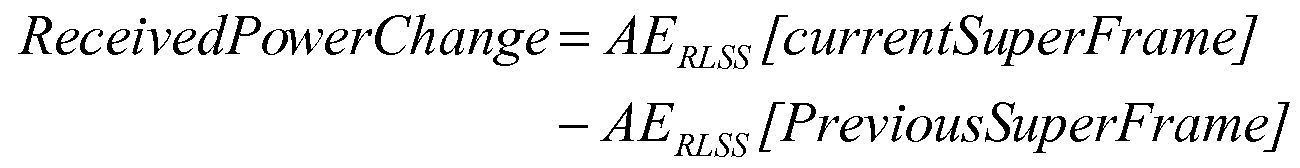
PCTRL 값은 하기의 규칙에 따라 PCTRL-수신 전력 변경의 최종 값으로 변화하며:The P CTRL value changes to the final value of P CTRL -received power change according to the following rules:
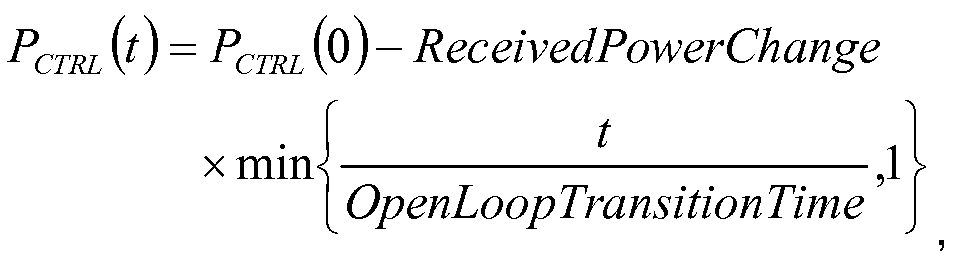
상기 t는 RLSS의 최종 수퍼 프레임 프리앰블 이래로 시간을 표시하며, 개방 루프 변화 시간과 동일한 유니트들 내에서 측정된다.The t represents time since the last super frame preamble of the RLSS and is measured in units equal to the open loop change time.
일 양상에서, 전력 제어 인터페이스(502)(모바일 디바이스(500)의 소프트웨어로 지칭될 수 있음)는 간섭 전력 PCTRL(dBm)에서 CDMA 제어 채널들을 전력 증폭기(508)를 프로그래밍함으로써 전송한다. 특히, 전력 제어 인터페이스(502)는 앞서 계산된 프로브 전력(dBm) 값을 x-비트 값으로 변환하여 이를 전력 증폭기 레지스터(510)로 전송하는 "AT_TX_GainCTL" 테이블을 사용한다. 상기 x-비트들은 원하는 전력으로 전송을 허용하는 전력 증폭기(508)로 시그널링된다.In one aspect, power control interface 502 (which may be referred to as software of mobile device 500) transmits CDMA control channels by
폐쇄 루프 전력 제어의 일 예에서, RLSS에 대한 RLCtrlPCMode는 '소거 기반' 으로 세팅된다(예컨대, '소거 기반' 전력 제어가 실행된다). 상기 모드에서, 모바일 디바이스(500)는 RLSS의 F-SSCH 내에서 RLSS에 대한 전력 제어 명령으로서 전송되는 모바일 디바이스용의 FL CEI 비트를 처리할 수 있다. 특히, 모바일 디바이스(500)는 상기 수학식 1에 따라 FL PHYFrame 인덱스 "f" 이전에 CDMA 제어 세그먼트를 포함하는 거의 인접한 RL PHYFrame에서 유효 R-CQICH 보고를 전송하는 경우에 인덱스 하기와 같이 계산되는 FL PHYFrame 인덱스들 "f"에서 FL CEI 비트를 모니터링한다.In one example of closed loop power control, RLCtrlPCMode for RLSS is set to 'erasing based' (eg, 'erasing based' power control is performed). In this mode, the
적절한 F0SSCH에 걸쳐 전송되는 CEI 비트가 1이면, 전력 업데이트 동작 동안 모바일 디바이스는 상응하는 PCTRL을 PowerControlStepUp(dB) 만큼 증가시킨다. 적절한 F-SSCH에 걸쳐 전송되는 CEI 비트가 0이면, 전력 업데이트 동안 모바일 디바이스는 상응하는 PCTRL을 PowerControlStepDown(dB) 만큼 감소시킨다. 상기 PCTRL의 변경들은 전술된 개방-루프 전력 제어 알고리즘에 의해 지시되는 임의의 변경들에 부가될 수 있다.If the CEI bit sent over the appropriate F0SSCH is 1, then during the power update operation the mobile device increments the corresponding P CTRL by PowerControlStepUp (dB). If the CEI bit transmitted over the appropriate F-SSCH is zero, then during the power update the mobile device reduces the corresponding P CTRL by PowerControlStepDown (dB). The changes in P CTRL may be added to any changes indicated by the open-loop power control algorithm described above.
일 양상에 따라, 전력 제어 인터페이스(502)는 업데이트된 기준 전력 PCTRL(dBㅡ)에서 CDMA 제어 채널들을 전력 증폭기(508)를 프로그래밍함으로써 전송할 수 있다. 특히, 전력 제어 인터페이스(502)는 상기 계산된 PCTRL(dBm) 값을 x-비트 값으로 변환하고 이를 전력 증폭기 레지스터(510)로 전송하는 AT_TX_GainCTL 테이블을 사용한다. 상기 x-비트들(상기 x는 9일 수 있음)은 그 후에 원하는 전력으로 전송을 허용하도록 전력 증폭기(508)로 시그널링된다. 모바일 디바이스(500) 는 RL CDMA 제어 채널들(기준 전력 PCTRL과 관련하여) 및 R-ACK 제어 채널의 상대 전력 레벨들을 "디지털로" 조정하며, 이의 설명이 하기에 제공된다.According to one aspect, the
일 양상에 따라, 만약 R-CQICH 보고가 FL 핸드오프 요청(모바일 디바이스는 핸드오프되지 않음)을 전달하지 않으면,According to one aspect, if the R-CQICH report does not carry an FL handoff request (mobile device is not handed off),
![]()
![]()
이를 달성하기 위해, 전력 제어 인터페이스(502)는 MOD_RCQICH 레지스터의 RCQICH_POWER 필드(s1.14)를 값 2-(14- REFLEVEL )로 세팅함으로써 변조기 블럭(512)을 프로그래밍할 수 있다. 만약 R-CQICH 리포트가 FL 핸드오프 요청을 전달하면(예컨대, DFLSS는 FLSS와 서로 다르고, CQI 보고는 CQICHCTRL이고, CQI 내의 활성 섹터 인덱스(ActiveSetIndex) 필드는 DFLSS의 활성 섹터 인덱스이며, CQI 내의 DFLSS는 '1'로 세팅됨), To accomplish this, the
![]()
![]()
이를 달성하기 위해, 전력 제어 인터페이스(502)는 MOD_RCQICH 레지스터의 RCQICH_POWER 필드(s1.14)를 하기의 값으로 세팅함으로써 변조기 블럭(512)을 프로그래밍할 수 있고:To accomplish this, the
![]()
![]()
상기 값은 s1.14 포맷에서 하기와 같이 해석된다:The value is interpreted as follows in the s1.14 format:

만약 R-CQICH 보고가 FL 핸드오프 요청을 전달하고, CQICHPowerBoostForHandoff가 0보다 크면, 모바일 디바이스(500)는 RLSS로부터의 소거 비트가 전력 다운을 표시하는 경우에 RLSS로부터 FL CEI를 무시한다. If the R-CQICH report carries an FL handoff request and CQICHPowerBoostForHandoff is greater than zero, the
일 양상에 따라, REQChannelGainj는 모든 RL QoS 레벨들 j에 대하여 동일하다. R-REQCH는 하기의 규칙들에 따라 RLSS 및 DRLSS에 대하여 계산될 수 있다: 만약 DRLSS가 RLSS와 다르면,According to one aspect, REQChannelGain j is the same for all RL QoS levels j. R-REQCH can be calculated for RLSS and DRLSS according to the following rules: If DRLSS is different from RLSS,
![]()
![]()
상기 전력 부스트들을 달성하기 위해, 전력 제어 인터페이스(502)는 하기와 같이 변조기 블럭(512)을 프로그래밍할 수 있다. 전력 제어 인터페이스(502)는 MOD_RREQCH 레지스터의 RREQCH_POWER 필드(s1.14)를 하기의 값으로 세팅할 수 있고:To achieve the power boosts, the
![]()
![]()
상기 s1.14에서 포맷에서 상기 값은 하기와 같이 해석된다:The value in format in s1.14 is interpreted as follows:

만약 DRLSS가 RLSS와 동일하면,If DRLSS is equal to RLSS,
![]()
![]()
상기 전력 부스트들을 달성하기 위해, 일 예에서 전력 제어 인터페이스(502)는 MOD_RREQCH 레지스터의 RREQCH_POWER 필드(s1.14)를 하기의 값으로 세팅할 수 있고:To achieve the power boosts, in one example the
![]()
![]()
s1.14 포맷에서 상기 값은 하기와 같이 해석된다:In s1.14 format the value is interpreted as follows:

일 양상에서, R-CQICH 및 R-REQCH와 달리, R-ACKCH는 OFDM 변조를 사용하여 전송될 수 있다. 예를 들어, R-ACKCH 송신 전력은 하기의 식에 따라 FLSS에 대해서만 계산될 수 있다:In one aspect, unlike the R-CQICH and R-REQCH, the R-ACKCH may be transmitted using OFDM modulation. For example, the R-ACKCH transmit power can be calculated only for FLSS according to the following equation:

ACKChannelGain은 프로그래밍 가능한 OA&M 파라미터를 조정하며, 하기의 제약들을 세팅한다:ACKChannelGain adjusts programmable OA & M parameters and sets the following constraints:

상기 ICDMA는 표시자 함수이다. ICDMA=1은 RL CDMA 제어 세그먼트를 포함하는 RL PHYFrame을 표시하고, ICDMA=0은 RL CDMA 제어 세그먼트를 포함하지 않는 RL PHYFrame을 표시하며, 상기 NACK=8은 임의의 주어진 OFDM 심볼에 대한 ACK 서브-캐리어들의 개수이다.I CDMA is an indicator function. I CDMA = 1 indicates an RL PHYFrame that includes an RL CDMA control segment, I CDMA = 0 indicates an RL PHYFrame that does not include an RL CDMA control segment, wherein N ACK = 8 for any given OFDM symbol. The number of ACK sub-carriers.
전술된 설명은 RACK 전송 PSD가 R-DCH 전송보다 강한 ACKChannelGainAdjustment(dB)가 되도록 보장할 수 있다. 일부 상황들 중, 특히 ACK-대-NACK 검출이 사용되지 않는 상황에서 R-ACK는 ACK-대-NACK 에러를 최소화하기 위해 더 R-DCH보다 더 높은 PSD로 전송될 수 있음이 인식될 것이다. 적절한 전력의 R-ACK 전송을 제공하기 위해, 전력 제어 인터페이스(502)는 R-ACKCH 패킷 서술자의 RACKCH_POWER 필드(s2.13)를 하기의 값으로 세팅함으로써 변조기 블럭(512)을 프로그래밍할 수 있다:The foregoing description may ensure that the RACK transmission PSD is a stronger ACKChannelGainAdjustment (dB) than the R-DCH transmission. It will be appreciated that some of the situations, especially in the case where ACK-to-NACK detection is not used, may be sent with a higher PSD than the R-DCH to minimize the ACK-to-NACK error. To provide proper power R-ACK transmission,

s2.13 포맷에서 상기 값은 하기와 같이 해석된다:In the s2.13 format the value is interpreted as follows:

또다른 양상에 따라, 주어진 RL-ATA에 대하여, 모바일 디바이스(500)는 RDCHGain에 비례하는 인자만큼 RL CDMA 제어 채널과 관련된 R-DCH 채널의 디지털 이득을 조정할 수 있다. 이는 "델타-기반 전력 제어"로 지칭된다. 일 예에서, 파라미터 RDCHGain는 하기에서 논의되는 것과 같이 CDMA 제어 채널을 가진 RL 프레임들에 대하여 한정된다.According to another aspect, for a given RL-ATA,
만약 모바일 디바이스(500)가 CDMA 제어 세그먼트를 가지는 RL 프레임에 상응하는 RL-ATA를 가지면, 모바일 디바이스(500)는 전체 전력 증폭기 제한들에 의해 허용되는 최고 RDCHGain을 가진 RDCH 서브 캐리어들을 전송할 수 있다. 만약 RDCHGain > RDCHGainMax이면, 모바일 디바이스(500)는 RDCHGainMax로 R-DCH 서브 캐리어들을 전송할 수 있다. 다음에, 모바일 디바이스(500)는 전체 전력 증폭기 제한들 및 앞서 계산된 RDCHGain을 가정하여 연관된 최대 지원가능한 서브 캐리어들을 계산할 수 있다. 만약 최대 지원가능한 서브 캐리어들이 16개 톤들 미만이면, 모바일 디바이스(500)는 최대 지원 가능한 서브 캐리어들이 16개 톤들과 동일하다고 가정하고 상응하는 RDCHGain을 계산한다. 모바일 디바이스는 그 후에 RTC-MAC 패킷의 MAC 헤더의 InBandPowerControl 블럭에서 튜플 [RDCHGain and MaxSubCarriers]을 보고한다. 이는 AP RL-스케줄러 알고리즘이 향후 전송들을 위 해 적절한 RL-ATA를 결정하도록 지원한다.If
만약 모바일 디바이스(500)가 "아니오(NO)" CDMA 제어 세그먼트를 가지는 RL 프레임에 상응하는 유효 RL-AT를 가지면, 모바일 디바이스(500)는 전체 전력 증폭기 제한들에 의해 허용되는 최고 전력 스펙트럼 밀도(RDCHGainNonRLCC라 부름)로 R-DCH 서브 캐리어들을 전송할 수 있다. 만약 RDCHGainNonRLCC > RDCHGainMax이면, 모바일 디바이스(500)는 RDCHGainMax로 R-DCH 서브 캐리어들을 전송할 수 있다. 모바일 디바이스(500)는 RDCHGainMax, 전체 전력 증폭기 제한들 및 CDMA 제어 세그먼트를 가진 RL 프레임의 존재를 가정하여 최대 지원가능한 서브 캐리어들을 계산할 수 있다. 만약 최대 지원가능한 서브 캐리어들이 16개 톤들 미만이면, 모바일 디바이스(500)는 최대 지원가능한 서브 캐리어들이 16개 톤들과 동일하다고 가정하여 상응하는 RDCHGain을 계산할 수 있다. 모바일 디바이스(410)는 RTC-MAC 패킷의 MAC 헤더의 InBandPowerControl 블럭에서 튜플[RDCHGain 및 MaxSubCarriers]를 보고할 수 있다. 이는 AP RL 스케줄러 알고리즘이 향후 전송들을 위한 적절한 RL-ATA를 결정하는 것을 지원한다.If the
CDMA RLCC를 포함하는 RL PHYFrames에 대하여, 전력 제어 인터페이스(502)는 MOD_FD_BUFF의 전력 밀도(s2.13)을 하기의 값으로 세팅함으로써 변조기 블럭(512)을 프로그래밍할 수 있고:For RL PHYFrames that include a CDMA RLCC, the

s2.13 포맷에서 상기 값은 하기와 같이 해석된다:In the s2.13 format the value is interpreted as follows:

CDMA RLCC를 포함하지 않는 RL PHYFrames에 대하여, 전력 제어 인터페이스(502)는 MOD_FD_BUFF의 전력 밀도(s2.13)을 하기의 값으로 세팅함으로써 변조기 블럭(512)을 프로그래밍할 수 있고:For RL PHYFrames that do not include a CDMA RLCC, the

s2.13 포맷에서 상기 값은 하기와 같이 해석된다:In the s2.13 format the value is interpreted as follows:

RDCHGainNonRLCC 파라미터는 RL CDMA 제어 세그먼트를 포함하지 않는 RL PHYFrames에 대해서만 계산되는 것이 인식될 것이다.It will be appreciated that the RDCHGain NonRLCC parameter is calculated only for RL PHYFrames that do not contain an RL CDMA control segment.
일 양상에서, 모바일 디바이스(500)는 RL 패킷의 대역 내 MAC 헤더(InBandPowerControlBlock 내의)를 통해 RDCHGainMax에 대한 최대 지원가능한 서브 캐리어들(MaxSubCarriers)을 보고한다. 최대 지원가능한 서브 캐리어 들(MaxSubCarriers)이 16보다 작은 경우에 MaxSubCarriers는 16으로 세팅되고 RDCHGainMax 미만의 상응하는 RDCHGain이 보고되는 경우는 제외된다. 전술된 것과 같이, RDCHGain은 RL CDMA 제어 세그먼트를 가지는 RL PHYFrames에 대해서만 계산된다.In one aspect,
일 양상에 따라, 최대 지원가능한 서브 캐리어들은 하기와 같이 Nc=Nc,MAX를 풀어서 계산되며:According to one aspect, the maximum supportable subcarriers are calculated by solving Nc = Nc, MAX as follows:
![]()
![]()
상기 식에서In the above formula

만약 앞서 계산된 Nc,MAX가 16개 톤들보다 작으면, Nc,MAX는 16과 동일하게 세팅되며, 상응하는 RDCHGain은 하기와 같이 계산된다: If Nc, MAX calculated earlier than 16 tones, Nc, MAX is set equal to 16, and the corresponding RDCHGain is calculated as follows:

폐쇄 루프 제어의 일 예에서, RL CDMA 채널을 통한 폐쇄 루프 전력 제어는 모바일 디바이스(500)가 RL 링크를 폐쇄하도록 할 수 있다. 또한, 페이딩 및 간섭을 보상하도록 사용될 수 있다(제어 채널에 H-ARQ가 존재하지 않기 때문에). RL CDMA 채널에서 폐쇄 루프 전력 제어는 추가로 CDMA 제어 채널에서 "니어-파(near-far)" 영향을 방지하고 및/또는 모바일 디바이스에서 가능하면 많이 에너지를 보존하기 위해 추가로 사용될 수 있으며, 따라서 최소 전력을 전송하는 각각의 사용자(예컨대, 모바일 디바이스)가 링크를 폐쇄하기 위해 요구된다. 부가적으로 또는 선택적으로, RL CDMA 채널을 통한 폐쇄 루프 전력 제어는 다른 섹터들에 대한 간섭을 완화하기 위해 사용될 수 있다.In one example of closed loop control, closed loop power control over the RL CDMA channel may cause the
폐쇄 루프 전력 제어는 2개의 모드들:소거 기반 폐쇄 루프 전력 제어 및/또는 업다운 기반 전력 제어로 동작할 수 있다. 소거 기반 폐쇄 루프 전력 제어에서, 모바일 디바이스는 액세스 포인트로부터 전송된 소거 비트들에 기반하여 기준 전력을 업데이트한다. 업다운 기반 전력 제어에서, 모바일 디바이스의 전력 제어는 액세스 포인트로부터 전송된 업다운 전력 제어에 기반하여 업데이트된다. RL CDMA 제어 채널들(R-CQICH 및 R-REQCH)는 소거 디코딩을 가정할 때 액세스 포인트 에 의해 디코딩된다. 상기 채널에서 하기의 결과가 발생될 수 있다:Closed loop power control can operate in two modes: erase based closed loop power control and / or up-down based power control. In erase based closed loop power control, the mobile device updates the reference power based on the erase bits sent from the access point. In updown based power control, the power control of the mobile device is updated based on the updown power control sent from the access point. The RL CDMA control channels (R-CQICH and R-REQCH) are decoded by the access point assuming erasure decoding. The following results may occur in the channel:
소거 기반 전력 제어를 위해, 액세스 포인트는 하기의 식에 따라 소거 명령들을 모바일 디바이스로 전송함으로써 타겟 소거 레이트를 보장할 수 있다:For erase based power control, the access point can ensure the target erase rate by sending erase commands to the mobile device according to the following equation:
![]()
![]()
델타 기반 전력 제어의 일 예는 하기와 같이 구현될 수 있다. 주어진 RL-ATA에 대하여, R-DCH 채널들은 RDCHGain에 비례하는 인자만큼 RL CDMA 제어 채널과 관련하여 전력 부스트된다. 이는 "델타 기반 전력 제어"라 지칭된다. 델타 기반 전력 제어의 기본 원리는 모바일 디바이스가 셀내 간섭 및 셀간 간섭을 생성하지 않고 가능하면 많은 (max PA 전력)을 전송하는 것이다.An example of delta based power control may be implemented as follows. For a given RL-ATA, the R-DCH channels are power boosted with respect to the RL CDMA control channel by a factor proportional to the RDCHGain. This is referred to as "delta based power control". The basic principle of delta-based power control is for a mobile device to transmit as much (max PA power) as possible without generating intracell and intercell interference.
특정 모바일 디바이스 수신 전력이 동일한 PHYFrame에서 인접 주파수 자원들을 가지는 다른 모바일 디바이스들과 관련하여 실질적으로 더 높을 때 셀내 간섭은 액세스 포인트에서 ICI에 의해 발생된다. 상기 ICI의 영향은 RDCHGain을 인자 RDCHGainMax로 제한함으로써 완화되며, 후자의 경우는 활성 세트 메세지 프로토콜에서 정의된다. 일반적으로, 이는 RDCHGainMin <= RDCHGain <= RDCHGainMax을 결과로 한다. RDCHGainMin은 에지 사용자들(예컨대, 모바일 디바이스)에 대한 최대 타겟 레이트를 달성하기 위해 세팅될 수 있다. RDCHGainMax는 ICI 마진을 만족하기 위해 RDCHGainMin로 고정될 수 있다. Intracell interference is generated by the ICI at an access point when a particular mobile device received power is substantially higher with respect to other mobile devices having adjacent frequency resources in the same PHYFrame. The effect of the ICI is mitigated by limiting the RDCHGain to the factor RDCHGainMax, the latter case being defined in the active set message protocol. In general, this results in RDCHGainMin <= RDCHGain <= RDCHGainMax. RDCHGainMin may be set to achieve a maximum target rate for edge users (eg, mobile device). RDCHGainMax can be fixed to RDCHGainMin to satisfy the ICI margin.
셀간 간섭은 수퍼프레임 프리앰블 에서 전송된 다른 섹터 간섭(OSI) 및 RLSS와는 다른 섹터들로부터 F-SSCH를 통해 전송된 고속의 다른 OSI 비트들뿐만 아니라 상기 섹터들에 대한 측정된 ChanDiff(특정 섹터와 RLSS 사이의 경로 손실의 차이)에 기초하여 RDCHGain 파라미터를 업데이트함으로써 제어될 수 있다. 그러나, 일부 예들에서 전력 제어의 상기 양상이 구현되지 않을 수 있음이 인식될 것이다.Inter-cell interference is measured for other sector interferences (OSIs) transmitted in the superframe preamble and other OSI bits transmitted over the F-SSCH from sectors other than the RLSS, as well as measured ChanDiff (specific sectors and RLSS for those sectors). Can be controlled by updating the RDCHGain parameter based on the difference in pathloss between the two). However, it will be appreciated that in some examples the above aspect of power control may not be implemented.
일 양상에 따라, 액세스 포인트는 모바일 디바이스가 RLAB에서 전송된 RDCHGain 값으로 전송하도록 함으로써 결함이 있는 모바일 디바이스를 전력 제어하도록 허용될 수 있다. 시스템 성능의 관점에서, 섹터 스루풋율을 최대화하기 위해 개념적으로 "강한" 사용자들은 높은 RDCHGain으로 전송해야 하고, "약한" 사용자들은 낮은 RDCHGain으로 전송해야 한다.According to one aspect, the access point may be allowed to power control the defective mobile device by having the mobile device transmit the RDCHGain value sent in the RLAB. In terms of system performance, to maximize sector throughput, conceptually "strong" users should transmit at high RDCHGain and "weak" users should transmit at low RDCHGain.
RDCHGain 계산의 일 예에서, RL CDMA 제어 세그먼트를 가지는 RL 프레임들에 대하여 R-DCH의 전력 PDCH는 하기와 같이 계산될 수 있다:In one example of the RDCHGain calculation, the power PDCH of the R-DCH for RL frames having an RL CDMA control segment may be calculated as follows:

R-ACKCH 송신 전력은 하기의 식에 따라 FLSS에 대해서만 계산될 수 있다:R-ACKCH transmit power can be calculated only for FLSS according to the following equation:

일 예에서, 하기의 제약들이 가정될 수 있고:In one example, the following constraints can be assumed:

따라서,therefore,
모바일 디바이스 전력 증폭기 제한들은 하기의 식을 발생하며,Mobile device power amplifier limits produce the equation
![]()
![]()
상기 아래 첨자 "LIN"은 선형 영역에서 계산된 값을 지칭한다. 다시 말해서:The subscript "LIN" refers to the value calculated in the linear region. In other words:

따라서:therefore:

상기 식들을 등식화하면 다음과 같다:Equalizing the above equations:

RDCHGainNONRLCC 계산의 일 예에서, RDCHGainNonRLCC 파라미터는 RL CDMA 제어 세그먼트를 포함하지 않는 RL PHYFrames에 대해서만 계산된다. CDMA RLCC를 가지지 않는 PHYFrames에 대하여, R-DCH의 전력은 하기의 식에 따라 계산될 수 있다:In one example of the RDCHGainNONRLCC calculation, the RDCHGain NonRLCC parameter is calculated only for RL PHYFrames that do not contain an RL CDMA control segment. For PHYFrames without a CDMA RLCC, the power of the R-DCH can be calculated according to the following equation:
![]()
![]()
전술된 것과 유사한 논의가 하기에 제시된다:A discussion similar to that described above is presented below:

앞서 도시되고 논의된 예시적인 시스템들의 관점에서, 개시된 주제에 따라 구현될 수 있는 방법들은 하기의 흐름도들을 참조하여 더 잘 이해될 것이다. 설명 을 간단히 하기 위해, 상기 방법들은 일련의 블럭들로 도시되고 설명되지만, 청구되는 주제는 일부 블럭들이 본 명세서 내에 도시되고 설명되는 다른 블럭과 서로 다른 순서들로 발생하거나 동시에 발생할 수 있기 때문에 블럭들의 번호 또는 순서에 의해 제한되지 않음이 이해되고 인식될 것이다. 또한, 하기에서 설명되는 방법들을 구현하기 위해 설명된 모든 블럭들이 필요하지는 않다. 블럭들과 연관된 기능은 소프트웨어, 하드웨어, 이들의 조합, 또는 임의의 다른 적절한 수단들(예컨대, 디바이스, 시스템, 프로세스, 컴포넌트)에 의해 구현될 수 있음이 인식될 것이다. 추가로 하기에 개시된 방법들 및 이를 통한 설명은 상기 방법들을 다양한 디바이스들로 용이하게 전환하기 위한 제조물에 저장될 수 있음이 추가로 인식되어야 한다. 당업자는 선택적으로 방법이 상태 다이어그램 내에서와 같이 일련의 서로 연관된 상태들 또는 이벤트들로서 표시될 수 있음을 인식하고 이해할 것이다.In view of the exemplary systems shown and discussed above, methods that may be implemented in accordance with the disclosed subject matter will be better understood with reference to the following flow diagrams. For simplicity of explanation, the methods are shown and described in a series of blocks, but the claimed subject matter is that some of the blocks may occur in different order or concurrently with other blocks shown and described herein. It will be understood and appreciated that it is not limited by number or order. Moreover, not all the blocks described in order to implement the methods described below are required. It will be appreciated that the functionality associated with the blocks may be implemented by software, hardware, a combination thereof, or any other suitable means (eg, device, system, process, component). It should further be appreciated that the methods disclosed below and descriptions therethrough may be stored in an article of manufacture for easily converting the methods into various devices. Those skilled in the art will optionally recognize and understand that a method may be represented as a series of interrelated states or events, such as in a state diagram.
도 6을 참조하여, 무선 통신 시스템에서 다수의 변조 파형들의 전력 제어를 위한 방법(600)이 도시된다. 일부 양상들에 따라, 방법(600)은 CDMA 채널들 및 OFDMA 채널들 모두와 같은 다수의 변조 파형들의 채널들을 제어할 수 있다. 방법(600)은 모바일 디바이스가 액세스 프로브를 전송하는 시점에 사용될 수 있고, 단말기가 안정 상태에 진입할 때까지 또는 다른 시간들 동안 무선 통신 시스템 내에 포함된다. Referring to FIG. 6, a
방법(600)은 602에서 시작하여 기준 전력 레벨이 설정된다. 기준 전력 레벨은 제 1 변조 파형(예컨대, CDMA)의 역방향 링크 제어 채널을 위한 것일 수 있다. 전력 레벨은 개방 루프 전력 제어 및 폐쇄 루프 전력 제어를 사용하여 설정될 수 있다. 기준 전력 레벨을 세팅하기 위해 개방 루프 전력 제어를 사용하는 것은 연속하는 수퍼 프레임 프리앰블 간격들 동안 역방향 링크 서빙 섹터로부터 평균 수신 전력의 차이를 사용하는 것을 포함한다. 기준 전력 레벨을 세팅하기 위해 폐쇄 루프 전력 제어를 사용하는 두 가지 방식들이 존재한다: 소거 기반의 폐쇄 루프 전력 제어 및 업다운 기반의 폐쇄 루프 전력 제어. 소거 기반의 폐쇄 루프 전력 제어를 위해, 액세스 포인트로부터 수신된 소거 비트들은 기준 전력 레벨을 업데이트하기 위해 사용된다. 업다운 기반의 전력 제어를 위해, 액세스 포인트로부터 수신된 업다운 전력 제어 비트들은 기준 전력 레벨을 업데이트하기 위해 사용된다. 일부 양상들에 따라, 개방 루프 전력 제어 및 폐쇄 루프 전력 제어를 사용하여 제 1 변조 파형의 역방향 링크 제어 채널에 대한 기준 전력 레벨을 세팅하는 것은 식 ![]()
![]()
604에서, 역방향 링크 제어 채널의 디지털 이득은 기준 전력 레벨의 함수로서 조정된다. 역방향 링크 제어 채널은 제 2 변조 파형(예컨대, OFDMA)의 역방향 링크 제어 채널이 될 수 있다. 역방향 링크 제어 채널의 디지털 이득은 역방향 링크 제어 채널 이득에 비례하는 인자에 의해 조정될 수 있다. 일부 양상들에 따라, 디지털 이득은 역방향 링크 다중 변조 파형(예컨대, OFDMA-CDMA) 송신기의 IFFT 스테이지 이전의 변조기 블럭에 적용된다.At 604, the digital gain of the reverse link control channel is adjusted as a function of the reference power level. The reverse link control channel may be a reverse link control channel of a second modulation waveform (eg, OFDMA). The digital gain of the reverse link control channel can be adjusted by a factor proportional to the reverse link control channel gain. According to some aspects, the digital gain is applied to a modulator block before the IFFT stage of a reverse link multiple modulation waveform (eg, OFDMA-CDMA) transmitter.
606에서, 역방향 링크 데이터 채널의 디지털 이득이 조정된다. 역방향 데이터 채널은 제 2 변조 파형의 역방향 링크 데이터 채널이 될 수 있다. 602에서 세팅된 기준 전력 레벨과 관련하여 조정이 이루어질 수 있다. 일부 양상들에 따라, 역방향 데이터 채널 이득에 비례하는 인자만큼 조정이 이루어질 수 있다. 부가적으로 또는 선택적으로, 디지털 이득은 역방향 링크 다중 변조 파형 송신기의 IFFT 스테이지 이전의 변조기 블럭에 적용될 수 있다.At 606, the digital gain of the reverse link data channel is adjusted. The reverse data channel can be the reverse link data channel of the second modulation waveform. Adjustments may be made in relation to the reference power level set at 602. According to some aspects, adjustment may be made by a factor proportional to the reverse data channel gain. Additionally or alternatively, the digital gain may be applied to the modulator block before the IFFT stage of the reverse link multiple modulation waveform transmitter.
일부 양상들에 따라, 역방향 링크 데이터 채널 및 역방향 링크 제어 채널 모두의 디지털 이득은 최대 미리 결정된 이득으로 제한될 수 있다. 디지털 이득들을 제한하는 것은 무선 통신 시스템 내에서 다른 모바일 디바이스들에 발생되는 간섭을 완화시킬 수 있다. 다른 양상들에 따라, 역방향 링크 데이터 채널 및 역방향 링크 제어 채널 모두의 디지털 이득들은 제 1 변조 파형의 채널이 역방향 링크 전송 프레임 내에 존재하지 않는 경우에 전력 부스트될 수 있다.According to some aspects, the digital gain of both the reverse link data channel and the reverse link control channel may be limited to a maximum predetermined gain. Limiting digital gains can mitigate interference caused to other mobile devices within the wireless communication system. According to other aspects, the digital gains of both the reverse link data channel and the reverse link control channel may be power boosted if the channel of the first modulation waveform is not present in the reverse link transmission frame.
추가로, 일부 양상들에 따라, 방법(600)은 전송될 수 있는 최대 개수의 역방향 링크 데이터-서브 캐리어들에서 세부 부분들을 포함할 수 있는 대역 내 또는 대역 외 메세지를 액세스 포인트로 전송하는 것을 포함할 수 있다. 상기 최대 개수의 역방향 링크 데이터-서브 캐리어들은 전력 증폭기의 제한들 및/또는 최대 미리 결정된 이득 제한들의 인자가 될 수 있다.In addition, in accordance with some aspects, the
도 7은 다중 변조 파형들의 전력 제어를 위한 또다른 방법(700)을 도시한다. 방법(700)은 702에서 시작하며, 액세스 프로브가 전송된다. 액세스 프로브는 모바일 디바이스가 유휴 상태에서 접속 상태로 변환하는 것을 원할 때 전송된다. 액세 스 프로브가 전송되면, 모바일 디바이스가 데이터를 전송하지 않기 때문에 단 하나의 채널만이 사용가능하다. 액세스 프로브는 RLSS로부터 측정된 평균 수신 전력에 비례할 수 있는 프로브 전력으로 전송된다. 연속하는 액세스 프로브들은 액세스 허가가 수신되어 성공적으로 디코딩될 때까지 더 높은 전력 레벨로 전송될 수 있다. 7 shows another
액세스 프로브 내에서 전송될 초기 전력을 결정하기 위해, 모바일 디바이스는 다수의 섹터들로부터 전력을 수신할 수 있다. 액세스 프로브가 전송될 섹터로부터의 전력은 섹터 당 평균 수신 전력 및 안테나당 추정 에너지를 참조하고 상기 수학식 2 및 수학식 3을 참조하여 전술된 것과 같이 결정된다. 따라서, 모바일 디바이스는 모든 섹터들로부터 전체 전력의 합을 수신한다. 따라서, 모바일 디바이스는 섹터 당 전송된 전력을 결정하고 적어도 하나의 섹터를 식별한다.To determine the initial power to be transmitted within the access probe, the mobile device can receive power from multiple sectors. The power from the sector to which the access probe is to be transmitted is determined as described above with reference to Equations 2 and 3 above with reference to average received power per sector and estimated energy per antenna. Thus, the mobile device receives the sum of the total power from all sectors. Thus, the mobile device determines the transmitted power per sector and identifies at least one sector.
액세스 허가가 성공적으로 디코딩되는 것과 실질적으로 동시에, 제 1 변조 파형(예컨대, CDMA)의 기준 채널의 전력 레벨이 조정된다(704). 제 1 변조 파형 기준 채널 레벨이 조정된 후에, 706에서 다른 채널들의 전력 세팅은 제 1 변조 파형의 제어 채널과 관련하여 조정된다. 상기 조정은 변조기 블럭에 의해 수행될 수 있고 디지털로 수행될 수 있다. 예를 들어, 706에서 다수 채널들의 디지털 이득들이 조정될 수 있다. 상기 채널들은 REQ, CQI 및 ACK 제어 채널들을 포함한다. 채널들의 디지털 이득들은 상기 채널들이 제 1 변조 파형(예컨대, CDMA) RL 기준 전력과 관련하여 전력 부스트되도록 조정될 수 있다. R-DCH 채널의 디지털 이득은 RDCHGain에 비례하는 인자만큼 조정될 수 있다. 몇몇 양상들에 따라, 튜플은 RTC- MAC 패킷의 MAC 헤더의 InBandPowerControl 블럭에서 보고된다. At substantially the same time as the access grant is successfully decoded, the power level of the reference channel of the first modulation waveform (eg, CDMA) is adjusted (704). After the first modulation waveform reference channel level is adjusted, the power settings of the other channels are adjusted in relation to the control channel of the first modulation waveform at 706. The adjustment may be performed by a modulator block and may be performed digitally. For example, the digital gains of multiple channels may be adjusted at 706. The channels include REQ, CQI and ACK control channels. The digital gains of the channels may be adjusted such that the channels are power boosted with respect to a first modulation waveform (eg, CDMA) RL reference power. The digital gain of the R-DCH channel can be adjusted by a factor proportional to the RDCHGain. According to some aspects, the tuple is reported in the InBandPowerControl block of the MAC header of the RTC-MAC packet.
708에서, 나머지 전력은 데이터 채널들에 할당된다. 몇몇 양상들에 따라, RDCH의 추가 이득들이 조정된다. RDCH 채널들을 조정한 이후에, RDDCH 이득을 포함하는 메세지가 기지국에 전송될 수 있다. (피드백) 메세지는 모바일 디바이스에서 사용가능한 전력이 주어질 때 지원될 수 있는 대역폭의 기지국을 통지한다. 상기 정보에 기초하여 기지국은 단말기에서 사용가능한 전력의 양 및 단말기에 할당될 수 있는 서브 캐리어들(할당)의 개수를 결정할 수 있다.At 708, the remaining power is allocated to the data channels. According to some aspects, additional gains of the RDCH are adjusted. After adjusting the RDCH channels, a message including the RDDCH gain may be sent to the base station. The (feedback) message informs the base station of the bandwidth that can be supported when given the power available at the mobile device. Based on the information, the base station can determine the amount of power available at the terminal and the number of subcarriers (allocation) that can be allocated to the terminal.
단말기가 주변을 이동할 수 있거나 단말기가 수신하는 전력은 전파 환경 (채널) 변경들로 인해 시간에 걸쳐 변화할 수 있으며, 따라서 기준 레벨은 계속해서 모니터되고 시간에 걸쳐 조정될 수 있다. 추가로, 수신 전력 또한 변화할 수 있다. 만약 기준 레벨이 변화하면, 아날로그 세팅이 될 수 있는 전력 증폭기 세팅은 조정된다.The terminal may move around or the power received by the terminal may change over time due to propagation environment (channel) changes, so that the reference level can be continuously monitored and adjusted over time. In addition, the received power may also vary. If the reference level changes, the power amplifier setting, which can be an analog setting, is adjusted.
제 1 변조 파형의 채널을 수신한 후에 기지국이 모바일 디바이스가 너무 높은 (또는 너무 낮은) 전력으로 전송한다고 결정하면 조정들이 수행되어야 한다. 만약 조정들이 필요하면, 기지국은 적절한 F-SSCH을 통해 전송되는 CEI 비트를 포함할 수 있는 피드백 메세지를 전송할 수 있다. 만약 수신된 CEI 비트가 "1"이면, 모바일 디바이스는 상응하는 PCTRL을 PowerControlStepUp dB만큼 증가시킬 수 있다. 만약 수신된 CEI 비트가 "0"이면, 모바일 디바이스는 상응하는 PCTRL을 PowerControlStepDown dB만큼 감소시킬 수 있다. 따라서, 본 명세서에서 설명되는 다양한 양상들은 무선 통신 환경에서 다중 변조 파형들의 전력 제어와 관련된다.Adjustments should be made if the base station determines that the mobile device transmits at too high (or too low) power after receiving the channel of the first modulation waveform. If adjustments are needed, the base station may send a feedback message that may include the CEI bit sent on the appropriate F-SSCH. If the received CEI bit is "1", the mobile device can increase the corresponding P CTRL by PowerControlStepUp dB. If the received CEI bit is "0", the mobile device can decrease the corresponding P CTRL by PowerControlStepDown dB. Accordingly, various aspects described herein relate to power control of multiple modulation waveforms in a wireless communication environment.
도 8을 참조하여, 하나 이상의 개시된 양상들에 따라 액세스 단말기에 대한 전력 제어를 용이하게 하는 시스템(800)이 설명된다. 시스템(800)은 예를 들어 수신기 안테나로부터 신호를 수신할 수 있는 수신기(802)를 포함한다. 수신기(802)는 수신된 신호를 필터링, 증폭, 다운 컨버팅하는 것과 같은 일반적인 동작들을 수행할 수 있다. 수신기(802)는 샘플들을 획득하기 위해 처리된 신호를 디지털화할 수 있다. 복조기(804)는 각각의 심볼 주기 동안 수신된 심볼들을 획득할 뿐만 아니라 수신된 심볼들을 프로세서(806)에 제공할 수 있다.Referring to FIG. 8, a
프로세서(806)는 수신기 컴포넌트(802)에 의해 수신된 정보를 분석하고 및/또는 송신기(808)에 의한 전송을 위한 정보를 생성하도록 지정된 프로세서가 될 수 있다. 부가적으로 또는 선택적으로, 프로세서(806)는 사용자 디바이스(800)의 하나 이상의 컴포넌트들을 제어하고, 수신기(802)에 의해 수신된 정보를 분석하고, 송신기(808)에 의한 전송을 위한 정보를 생성하며, 및/또는 사용자 디바이스(800)의 하나 이상의 컴포넌트들을 제어할 수 있다. 프로세서(806)는 추가 사용자 디바이스들과의 통신들을 조정할 수 있는 제어기 컴포넌트를 포함할 수 있다.
사용자 디바이스(800)는 프로세서(806)에 동작 가능하게 결합되어 통신들을 조정하는 전력 제어 조정과 관련된 정보 및 임의의 다른 적절한 정보를 저장할 수 있는 메모리(808)를 추가로 포함할 수 있다. 메모리(810)는 전력 제어와 연관된 프로토콜들을 추가로 저장할 수 있다. 본 명세서 내에서 설명되는 데이터 저장(예컨대, 메모리들) 컴포넌트들은 휘발성 메모리 또는 비휘발성 메모리가 될 수 있거 나, 휘발성 메모리 및 비휘발성 메모리 모두를 포함할 수 있음이 인식되어야 한다. 설명을 위해, 그러나 이에 제한되지 않고, 비휘발성 메모리는 판독 전용 메모리(ROM), 프로그래밍 가능한 ROM(PROM), 전기적으로 프로그래밍 가능한 ROM(EPROM), 전기적으로 소거가능한 ROM(EEPROM), 또는 플래시 메모리를 포함할 수 있다. 휘발성 메모리는 외부 캐시 메모리로 동작하는 랜덤 액세스 메모리(RAM)를 포함할 수 있다. 설명을 위해, 그러나 이에 제한되지 않고, RAM은 동기식 RAM(SRAM), 동적 RAM(DRAM), 동기식 DRAM(SDRAM), 이중 데이터 레이트 SDRAM(DDR SDRAM), 진보된 SDRAM(ESDRAM), 동기 링크 DRAM(SLDRAM) 및 직접 램버스(Rambus) RAM(DRRAM)과 같은 다양한 형태들로 사용가능하다. 시스템들 및/또는 방법들의 메모리(808)는 상기 타입 및 임의의 다른 적절한 타입의 메모리를 포함하지만 이에 제한되지 않는다. 사용자 디바이스(800)는 변조된 신호를 전송하는 심볼 변조기(812) 및 송신기(808)를 더 포함할 수 있다.The
수신기(802)는 개방 루프 전력 제어 및 폐쇄 루프 전력 제어를 사용하여 제 1 변조 파형의 역방향 링크 제어 채널에 대한 기준 전력 레벨을 세팅하는 전력 레벨 조정기(814)에 추가로 동작 가능하게 결합된다. 추가로, 수신기(802)는 기준 전력 레벨과 관련하여 제 2 변조 파형의 역방향 링크 제어 채널 및/또는 제 2 변조 파형의 역방향 링크 데이터 채널의 디지털 이득을 세팅하는 디지털 이득 조정기(816)에 동작가능하게 결합될 수 있다.
도 9는 예시적인 무선 통신 시스템(900)을 도시한다. 무선 통신 시스템(900)은 간단함을 위해 하나의 기지국 및 하나의 단말기를 도시한다. 그러나, 시스템(900)은 하나 이상의 기지국 또는 액세스 포인트 및/또는 하나 이상의 단말기 또는 사용자 디바이스를 포함할 수 있고, 상기 추가의 기지국들 및/또는 단말기들은 하기에서 논의되는 예시적인 기지국 및 단말기와 실질적으로 유사하거나 서로 상이할 수 있음이 인식될 것이다. 추가로, 기지국 및/또는 단말기는 본 명세서 내에서 설명되는 시스템들 및/또는 방법들을 사용하여 이들 사이의 무선 통신을 용이하게 할 수 있다.9 illustrates an example
도 9를 참조로 하여, 다운 링크를 통해 액세스 포인트(905)에서 송신(TX) 데이터 프로세서(910)는 트래픽 데이터를 수신하고, 포맷화하고, 코딩하고, 인터리빙하며, 변조(또는 심볼 맵핑)하여 변조 심볼들("데이터 심볼들")을 제공한다. 심볼 변조기(915)는 데이터 심볼들 및 파일럿 심볼들을 수신하여 처리하여 심볼들의 스트림을 제공한다. 심볼 변조기(915)는 데이터 및 파일럿 심볼들을 멀티플렉싱하여 N개 전송 심볼들의 세트를 획득한다. 각각의 전송 심볼은 데이터 심볼, 파일럿 심볼, 또는 0의 신호 값이 될 수 있다. 파일럿 심볼들은 각각의 심볼 주기 내에서 연속하여 전송될 수 있다. 파일럿 심볼들은 주파수 분할 멀티플렉싱(FDM), 직교 주파수 분할 멀티플렉싱(OFDM), 시간 분할 멀티플렉싱(TDM), 주파수 분할 멀티플렉싱(FDM) 또는 코드 분할 멀티플렉싱(CDM)이 될 수 있다.With reference to FIG. 9, the transmit (TX)
송신기 유니트(TMTR)(920)는 심볼들의 스트림을 수신하여 하나 이상의 아날로그 신호들로 변환하고 상기 아날로그 신호들을 추가 처리하여(예컨대, 증폭, 필터링 및 주파수 업 컨버팅) 무선 채널을 통한 전송에 적합한 다운 링크 신호를 생성한다. 다운 링크 신호는 안테나(925)를 통해 단말기들로 전송된다. 단말 기(930)에서, 안테나(935)는 다운 링크 신호를 수신하고 수신된 신호를 수신기 유니트(RCVR;940)에 제공한다. 수신기 유니트(940)는 수신된 신호를 처리(예컨대, 필터링, 증폭 및 주파수 다운 컨버팅)하고 처리된 신호를 디지털화하여 샘플들을 획득한다. 심볼 복조기(945)는 N개 수신 심볼들을 획득하여 수신된 파일럿 심볼들을 채널 추정용 프로세서(950)로 제공한다. 심볼 복조기(945)는 프로세서(950)로부터 다운링크에 대한 주파수 응답 추정치를 추가로 수신하고, 수신된 데이터 심볼들에 데이터 복조를 수행하여 데이터 심볼 추정치들(전송된 데이터 심볼들의 추정치들)을 획득하며, 데이터 심볼 추정치들을 전송된 트래픽 데이터를 복원하기 위해 데이터 심볼 추정치들을 복조(즉, 심볼 디맵핑), 디인터리빙 및 디코딩하는 RX 데이터 프로세서(955)에 제공한다. 심볼 복조기(945) 및 RX 데이터 프로세서(955)에 의한 프로세싱은 액세스 포인트(905)에서 심볼 변조기(915) 및 TX 데이터 프로세서(910)에 의한 프로세싱과 상호보완적이다. Transmitter unit (TMTR) 920 receives and converts a stream of symbols into one or more analog signals and further processes the analog signals (e.g., amplify, filter and frequency up-convert) to downlink suitable for transmission over a wireless channel. Generate a signal. The downlink signal is transmitted to the terminals via
업 링크에서, TX 데이터 프로세서(960)는 트래픽 데이터를 처리하여 데이터 심볼들을 제공한다. 심볼 변조기(965)는 데이터 심볼들을 수신하여 파일럿 심볼들로 멀티플렉싱하고, 변조를 수행하여 심볼들의 스트림을 제공한다. 송신기 유니트(970)는 심볼들의 스트림을 수신하고 처리하여 안테나(935)에 의해 액세스 포인트(905)로 전송된 업 링크 신호를 생성한다.In the uplink,
액세스 포인트(905)에서, 단말기(930)로부터의 업 링크 신호는 안테나(925)에 의해 수신되며 수신기 유니트(975)에 의해 처리되어 샘플들을 획득한다. 심볼 복조기(980)는 그 후에 샘플들을 처리하여 업 링크를 위한 수신 파일럿 심볼들 및 데이터 심볼 추정치들을 제공한다. RX 데이터 프로세서(985)는 단말기에 의해 전송된 트래픽 데이터를 복원하기 위해 데이터 심볼 추정치들을 처리한다. 프로세서(990)는 업 링크에서 전송하는 각각의 활성 단말기에 대하여 채널 추정을 수행한다.At the
프로세서들(990 및 950)은 액세스 포인트(905) 및 단말기(930) 각각에서 동작들을 감독한다(예컨대, 제어, 조정, 관리). 각각의 프로세서들(990 및 950)은 프로그램 코드들 및 데이터를 저장하는 메모리 유니트들(비도시)과 연관될 수 있다. 프로세서들(990 및 950)은 업 링크 및 다운 링크 각각에 대한 주파수 및 임펄스 응답 추정치들을 유도하기 위해 계산들을 수행할 수 있다.
다중 접속 시스템(예컨대, FDMA, OFDMA, CDMA, TDMA 등등)에 대하여, 다수의 단말기들은 업 링크에서 동시에 전송할 수 있다. 상기 시스템에 대하여, 파일럿 서브 대역들은 서로 다른 단말기들 사이에 공유될 수 있다. 채널 추정 기술들은 각각의 단말기에 대한 파일럿 서브 대역들이 전체 동작 대역(가능하면 대역 에지들은 제외하고)을 점유하는 경우들에 사용될 수 있다. 상기 파일럿 서브 대역 구조는 각각의 단말기에 대한 주파수 다이버시티를 획득하는 것이 바람직하다. 본 명세서에서 설명되는 기술들은 다양한 수단들에 의해 구현될 수 있다. 예를 들어, 상기 기술들은 하드웨어, 소프트웨어 또는 이들의 조합에서 구현될 수 있다. 하드웨어 구현에 대하여, 채널 추정을 위해 사용되는 프로세싱 유니트들은 하나 이상의 애플리케이션용 집적 회로들(ASICs), 디지털 신호 프로세서들(DSPs), 디지털 신호 프로세싱 디바이스들(DSPDs), 프로그램가능한 로직 디바이스들(PLDs), 현장 프로그 램 가능한 게이트 어레이들(FPGAs), 프로세서들, 제어기들, 마이크로-제어기들, 마이크로프로세서들, 본 명세서 내에 설명된 기능들을 수행하도록 설계된 다른 전자 유니트들 또는 이들의 조합 내에서 구현될 수 있다. 소프트웨어를 사용하여, 본 명세서 애세 설명된 기능들을 수행하는 모듈들을 통해 구현이 수행될 수 있다. 소프트웨어 코드들은 메모리 유니트 내에서 저장될 수 있고 프로세서들(990 및 950)에 의해 실행될 수 있다.For a multiple access system (eg FDMA, OFDMA, CDMA, TDMA, etc.), multiple terminals can transmit simultaneously on the uplink. For the system, pilot subbands can be shared between different terminals. Channel estimation techniques may be used in cases where pilot subbands for each terminal occupy the entire operating band (possibly except for band edges). The pilot subband structure preferably obtains frequency diversity for each terminal. The techniques described herein may be implemented by various means. For example, the techniques may be implemented in hardware, software, or a combination thereof. For a hardware implementation, the processing units used for channel estimation may include one or more application integrated circuits (ASICs), digital signal processors (DSPs), digital signal processing devices (DSPDs), programmable logic devices (PLDs). May be implemented in field programmable gate arrays (FPGAs), processors, controllers, micro-controllers, microprocessors, other electronic units designed to perform the functions described herein, or a combination thereof. have. Using software, implementation may be performed through modules that perform the functions described herein. Software codes may be stored in a memory unit and executed by
도 10을 참조하여, 서로 다른 변조 파형들을 사용하는 채널들에 대한 전력을 제어하는 예시적인 시스템(1000)이 설명된다. 예를 들어, 시스템(1000)은 모바일 디바이스 내에 적어도 부분적으로 상주할 수 있다. 시스템(100)은 프로세서, 소프트웨어 또는 이들의 조합(예컨대, 펌웨어)에 의해 구현되는 기능들을 설명하는 기능 블럭들이 될 수 있는 기능 블럭들을 포함하는 것으로 설명된다.Referring to FIG. 10, an
시스템(1000)은 개별적으로 또는 함께 동작할 수 있는 전기 컴포넌트들의 논리 그룹(1002)을 포함한다. 예를 들어, 논리 그룹(1002)은 기준 전력 레벨(1204)을 세팅하기 위한 전기 컴포넌트를 포함할 수 있다. 설명에 따라, 기준 전력 레벨은 제 1 변조 파형(예컨대, CDMA)의 역방향 링크 제어 채널을 위한 것이다. 기준 전력 레벨은 개방 루프 전력 제어 및 폐쇄 루프 전력 베어를 사용하여 세팅될 수 있다. 폐쇄 루프 전력 제어는 소거 기반 폐쇄 로프 전력 제어 및 업다운 기반 폐쇄 루프 전력 제어를 포함할 수 있다. 개방 루프 전력 제어는 연속하는 수퍼 프레임 프리앰블 간격들 동안 역방향 링크 서빙 섹터로부터 평균 수신 전력의 차이를 사용하는 것을 포함할 수 있다. 몇몇 양상들에 따라, 개방 루프 전력 제어 및 폐 쇄 루프 전력 제어를 사용하여 기준 전력 레벨을 세팅하는 것은 ![]()
![]()
논리 그룹(1002)은 기준 전력 레벨(1006)의 함수로서 제 2 변조 파형(예컨대, OFDMA)의 역방향 링크 전력 제어의 디지털 이득을 조정하기 위한 전기 컴포넌트를 포함할 수 있다. 제 2 변조 파형의 역방향 링크 전력 제어 채널의 디지털 이득은 역방향 링크 제어 채널 이득에 비례하는 인자만큼 조정될 수 있다.
추가로, 논리 그룹(1002)은 제 2 변조 파형(1008)의 역방향 링크 데이터 채널의 디지털 이득을 조정하기 위해 전기 컴포넌트를 포함할 수 있다. 예를 들어, 디지털 이득은 기준 전력 레벨과 관련하여 조정될 수 있다. 몇몇 양상들에 따라, 제 2 변조 파형의 역방향 링크 데이터 채널의 디지털 이득은 역방향 링크 데이터 채널 이득에 비례하는 인자만큼 조정될 수 있다.Additionally,
몇몇 양상들에 따라, 제 2 변조 파형의 역방향 링크 데이터 채널의 디지털 이득 및 제 2 변조 파형의 역방향 링크 제어 채널의 디지털 이득은 제 1 변조 파형의 채널이 역방향 링크 전송 프레임 내에 존재하지 않는 경우에 전력 부스트된다. 몇몇 양상들에 따라, 제 2 변조 파형의 역방향 링크 데이터 채널의 디지털 이득 및 제 2 변조 파형의 역방향 링크 제어 채널의 디지털 이득은 생성된 간섭량을 경감하기 위해 최대 미리 결정된 이득에 제한된다.According to some aspects, the digital gain of the reverse link data channel of the second modulation waveform and the digital gain of the reverse link control channel of the second modulation waveform are power when the channel of the first modulation waveform is not in the reverse link transmission frame. Is boosted. According to some aspects, the digital gain of the reverse link data channel of the second modulation waveform and the digital gain of the reverse link control channel of the second modulation waveform are limited to a maximum predetermined gain to mitigate the amount of interference produced.
부가적으로 또는 선택적으로, 대역 내 또는 대역 외 메세지(비도시)를 전송 하는 수단을 포함할 수 있다. 대역 내 또는 대역 외 메세지는 전송될 수 있는 최대 개수의 역방향 링크 데이터 서브 캐리어들의 세부 부분들을 포함할 수 있다. 최대 개수의 역방향 링크 데이터 서브 캐리어들은 전력 증폭기 제한들 및 최대 미리 결정된 이득 제한들에 종속될 수 있다.Additionally or alternatively, it may include means for transmitting an in-band or out-of-band message (not shown). The in-band or out-of-band message may include detail portions of the maximum number of reverse link data subcarriers that can be transmitted. The maximum number of reverse link data subcarriers may be subject to power amplifier limits and maximum predetermined gain limits.
부가적으로, 시스템(1000)은 전기 컴포넌트들(1004, 1006, 1008) 또는 다른 컴포넌트들과 연관된 기능들을 실행하기 위한 명령들을 저장하는 메모리(1010)를 포함할 수 있다. 메모리(1010) 외부에 존재하는 것으로 보여지지만, 하나 이상의 전기 컴포넌트들(1004, 1006, 1008)은 메모리(1010) 내에 존재할 수 있다. Additionally,
본 명세서 내에 개시된 실시예들은 하드웨어, 소프트웨어, 펌웨어, 미들웨어, 마이크로코드, 또는 이들의 임의의 조합에 의해 구현될 수 있음이 이해될 것이다. 시스템들 및/또는 방법들이 소프트웨어, 펌웨어, 미들웨어 또는 마이크로코드, 프로그램 코드 또는 코드 세그먼트들로 구현될 때, 이들은 저장 컴포넌트와 같은 기계-판독가능한 매체에 저장될 수 있다. 코드 세그먼트는 절차, 기능, 서브프로그램, 프로그램, 루틴, 서브루틴, 모듈, 소프트웨어 패키지, 클래스 또는 명령들, 데이터 구조들 또는 프로그램 상태들의 임의의 조합을 표시할 수 있다. 코드 세그먼트는 정보, 데이터, 인수들(arguments), 파라미터들, 또는 메모리 콘텐츠를 패스 및/또는 수용함으로써 또다른코드 세그먼트 또는 하드웨어 회로에 결합될 수 있다. 정보, 인수들, 파라미터들, 데이터 등등은 메모리 공유, 메모리 패싱, 토큰 패싱, 네트워크 전송 등등을 포함하는 임의의 적절한 수단들을 사용하여 통과되거나, 포워딩되거나, 전송될 수 있다.It is to be understood that the embodiments disclosed herein may be implemented by hardware, software, firmware, middleware, microcode, or any combination thereof. When the systems and / or methods are implemented in software, firmware, middleware or microcode, program code or code segments, they may be stored in a machine-readable medium such as a storage component. A code segment may represent a procedure, function, subprogram, program, routine, subroutine, module, software package, class or instruction, data structure, or any combination of program states. A code segment can be coupled to another code segment or hardware circuit by passing and / or accepting information, data, arguments, parameters, or memory content. Information, arguments, parameters, data, etc. can be passed, forwarded, or transmitted using any suitable means including memory sharing, memory passing, token passing, network transfer, and the like.
다양하게 설명되는 로직들, 로직 블럭들, 모듈들, 및 회로들은 범용 프로세서, 디지털 신호 처리기(DSP), 응용 집적 회로(ASIC), 현장 프로그램가능한 게이트 어레이(FPGA), 또는 다른 프로그램가능한 로직 디바이스, 이산 게이트 또는 트랜지스터 로직, 이산 하드웨어 컴포넌트들, 또는 본 명세서에 개시된 기능을 수행하도록 설계된 그들의 임의의 조합을 사용하여 실행되거나 수행될 수 있다. 범용 프로세서는 마이크로프로세서가 될 수 있지만, 선택적으로 프로세서는 임의의 종래의 프로세서, 제어기, 마이크로제어기, 또는 상태 기계가 될 수 있다. 프로세서는 또한 예를 들어, DSP 및 마이크로프로세서의 조합, 복수의 마이크로프로세서, DSP 코어와 결합된 하나 또는 그이상의 마이크로프로세서, 또는 임의의 다른 구성과 같은 컴퓨팅 장치들의 조합으로서 실행될 수 있다. 추가로, 적어도 하나의 프로세서는 전술된 하나 이상의 단계들 및/또는 동작들을 수행하도록 동작하는 하나 이상의 모듈들을 포함할 수 있다.The variously described logics, logic blocks, modules, and circuits may include general purpose processors, digital signal processors (DSPs), application integrated circuits (ASICs), field programmable gate arrays (FPGAs), or other programmable logic devices, It may be performed or performed using discrete gate or transistor logic, discrete hardware components, or any combination thereof designed to perform the functions disclosed herein. A general purpose processor may be a microprocessor, but in the alternative, the processor may be any conventional processor, controller, microcontroller, or state machine. A processor may also be implemented as a combination of computing devices, eg, a combination of a DSP and a microprocessor, a plurality of microprocessors, one or more microprocessors in conjunction with a DSP core, or any other configuration. In addition, the at least one processor may include one or more modules operative to perform the one or more steps and / or actions described above.
소프트웨어 구현에 대하여, 본 명세서에 개시된 기술들은 본 명세서에 개시된 기능들을 수행하는 모듈들(예컨대, 절차들, 기능들 등등)을 사용하여 구현될 수 있다. 소프트웨어 코드들은 프로세서들에 의해 실행되고 메모리 유니트들 내에 저장될 수 있다. 메모리 유니트는 프로세서 내부 또는 프로세서 외부에 구현될 수 있으며, 외부에 구현되는 경우에 당업자에게 공지된 것과 같은 다양한 수단들을 통해 프로세서에 통신가능하게 결합될 수 있다. 추가로, 적어도 하나의 프로세서는 본 명세서에 개시된 기능들을 수행하도록 동작하는 하나 이상의 모듈들을 포함할 수 있다.For software implementation, the techniques disclosed herein may be implemented using modules (eg, procedures, functions, etc.) that perform the functions disclosed herein. Software codes may be executed by the processors and stored in the memory units. The memory unit may be implemented within the processor or external to the processor, and when implemented externally, may be communicatively coupled to the processor through various means such as known to those skilled in the art. In addition, the at least one processor may include one or more modules operative to perform the functions disclosed herein.
또한, 본 명세서 내에 개시된 다양한 양상들 또는 특징들은 표준 프로그래밍 및/또는 엔지니어링 기술들을 사용하여 방법, 장치, 또는 제조물로 구현될 수 있다. 본 명세서 내에서 사용되는 용어 "제조물은" 임의의 컴퓨터 판독가능한 디바이스, 캐리어 또는 매체로부터 액세스 가능한 컴퓨터 프로그램을 포함한다. 예를 들어, 컴퓨터 판독가능한 매체는 자기 저장 디바이스(예컨대, 하드 디스크, 플로피 디스크, 자기 스트립 등), 광학 디스크들(예컨대, 휴대용 디스크(CD), 디지털 다용도 디스크(DVD) 등), 스마트 카드들 및 플래시 메모리 디바이스들(예컨대, EPROM, 카드, 스틱, 키 드라이브 등)을 포함할 수 있지만, 이에 제한되지 않는다. 추가로, 본 명세서 내에서 설명되는 다양한 저장 매체는 정보를 저장하기 위한 하나 이상의 디바이스들 및/또는 다른 기계 판독가능한 매체를 대표할 수 있다. 용어 "기계 판독가능한 매체"는 무선 채널들 및 명령(들) 및/또는 데이터를 저장하고, 포함하고, 및/또는 전달할 수 있는 다양한 다른 매체를 포함할 수 있지만, 이에 제한되지 않는다. 추가로, 컴퓨터 프로그램 제품은 컴퓨터가 본 명세서 내에 개시된 기능들을 수행하도록 동작하는 하나 이상의 명령들 또는 코드들을 가지는 컴퓨터 판독가능한 매체를 포함할 수 있다.In addition, various aspects or features disclosed herein may be implemented as a method, apparatus, or article of manufacture using standard programming and / or engineering techniques. As used herein, the term “article of manufacture” includes a computer program accessible from any computer readable device, carrier or media. For example, computer readable media may include magnetic storage devices (eg, hard disks, floppy disks, magnetic strips, etc.), optical disks (eg, portable disks (CDs), digital versatile disks (DVDs), etc.), smart cards And flash memory devices (eg, EPROM, card, stick, key drive, etc.). In addition, various storage media described herein can represent one or more devices and / or other machine-readable media for storing information. The term “machine-readable medium” may include, but is not limited to, various other media capable of storing, containing, and / or delivering wireless channels and command (s) and / or data. In addition, the computer program product may include a computer readable medium having one or more instructions or codes operative for the computer to perform the functions disclosed herein.
추가로, 본 명세서 내에 개시된 양상들과 관련하여 설명된 방법 또는 알고리즘의 단계들 및/또는 동작들은 하드웨어 내에서, 프로세서에 의해 실행되는 소프트웨어 모듈 내에서, 또는 상기 둘의 조합 내에서 직접 구현될 수 있다. 소프트웨어 모듈은 RAM 메모리, 플래시 메모리, ROM 메모리, EPROM 메모리, EEPROM 메모리, 레지스터들, 하드 디스크, 소거가능 디스크, CD-ROM 또는 당업자에게 공지된 임의의 다른 형태의 저장 매체 내에 상주할 수 있다. 예시적인 저장 매체는 프로세서에 결합될 수 있고, 상기 프로세서는 저장 매체로부터 정보를 판독하고 정보를 기록할 수있다. 선택적으로, 저장 매체는 프로세서에 통합될 수 있다. 추가로, 몇몇 양상들에서, 프로세서 및 저장 매체는 ASIC 내에 상주할 수 있다. 추가로, ASIC는 사용자 단말기 내에 상주할 수 있다. 선택적으로, 프로세서 및 저장 매체는 사용자 단말기 내에 이산 컴포넌트들로서 상주할 수 있다. 추가로, 몇몇 양상들에서, 방법 또는 알고리즘의 단계들 및/또는 동작들은 컴퓨터 프로그램 제품 내에 통합될 수 있는 기계 판독가능한 매체 및/또는 컴퓨터 판독가능한 매체에 코드들 및/또는 명령들 중 하나 또는 임의의 조합 또는 세트로 상주할 수 있다.In addition, the steps and / or operations of the method or algorithm described in connection with the aspects disclosed herein may be embodied directly in hardware, in a software module executed by a processor, or in a combination of the two. have. The software module may reside in RAM memory, flash memory, ROM memory, EPROM memory, EEPROM memory, registers, hard disk, erasable disk, CD-ROM or any other form of storage medium known to those skilled in the art. An exemplary storage medium can be coupled to the processor, which can read information from and write information to the storage medium. In the alternative, the storage medium may be integral to the processor. In addition, in some aspects the processor and the storage medium may reside within an ASIC. In addition, the ASIC may reside in a user terminal. In the alternative, the processor and the storage medium may reside as discrete components in a user terminal. In addition, in some aspects, the steps and / or actions of the method or algorithm may be one or any of codes and / or instructions on a machine-readable medium and / or computer-readable medium that can be incorporated into a computer program product. Can reside in a combination or set of
개시된 실시예의 전술된 설명은 당업자가 본 발명을 구현하고 이용하기에 용이하도록 하기 위하여 제공되었다. 이들 실시예에 대한 여러 가지 변형은 당업자에게 자명하며, 여기서 한정된 포괄적인 원리는 본 발명의 사용 없이도 다른 실시예에 적용될 수 있다. 따라서, 본 발명은 설명된 실시예에 한정되는 것이 아니며, 여기에 개시된 원리 및 신규한 특징에 나타낸 가장 넓은 범위에 따른다.The foregoing description of the disclosed embodiments is provided to enable any person skilled in the art to make or use the present invention. Various modifications to these embodiments will be apparent to those skilled in the art, and the generic principles defined herein may be applied to other embodiments without the use of the present invention. Accordingly, the invention is not limited to the described embodiments but is to be accorded the widest scope indicated in the principles and novel features disclosed herein.
Claims (37)
Applications Claiming Priority (5)
| Application Number | Priority Date | Filing Date | Title |
|---|---|---|---|
| US89697507P | 2007-03-26 | 2007-03-26 | |
| US60/896,975 | 2007-03-26 | ||
| US12/055,264 US8095166B2 (en) | 2007-03-26 | 2008-03-25 | Digital and analog power control for an OFDMA/CDMA access terminal |
| US12/055,264 | 2008-03-25 | ||
| PCT/US2008/058307 WO2008118982A1 (en) | 2007-03-26 | 2008-03-26 | Digital and analog power control for an ofdma/cdma access terminal |
Publications (2)
| Publication Number | Publication Date |
|---|---|
| KR20090132630A KR20090132630A (en) | 2009-12-30 |
| KR101136668B1 true KR101136668B1 (en) | 2012-05-24 |
Family
ID=39575912
Family Applications (1)
| Application Number | Title | Priority Date | Filing Date |
|---|---|---|---|
| KR1020097022342A Expired - Fee Related KR101136668B1 (en) | 2007-03-26 | 2008-03-26 | Digital and analog power control for an ofdma/cdma access terminal |
Country Status (10)
| Country | Link |
|---|---|
| US (1) | US8095166B2 (en) |
| EP (5) | EP2574119B1 (en) |
| JP (1) | JP5074576B2 (en) |
| KR (1) | KR101136668B1 (en) |
| CN (1) | CN101641876B (en) |
| BR (1) | BRPI0809466A2 (en) |
| CA (1) | CA2679823C (en) |
| RU (1) | RU2433533C2 (en) |
| TW (1) | TWI380722B (en) |
| WO (1) | WO2008118982A1 (en) |
Families Citing this family (32)
| Publication number | Priority date | Publication date | Assignee | Title |
|---|---|---|---|---|
| US5699275A (en) | 1995-04-12 | 1997-12-16 | Highwaymaster Communications, Inc. | System and method for remote patching of operating code located in a mobile unit |
| US8452316B2 (en) * | 2004-06-18 | 2013-05-28 | Qualcomm Incorporated | Power control for a wireless communication system utilizing orthogonal multiplexing |
| US7197692B2 (en) | 2004-06-18 | 2007-03-27 | Qualcomm Incorporated | Robust erasure detection and erasure-rate-based closed loop power control |
| KR100725773B1 (en) * | 2004-08-20 | 2007-06-08 | 삼성전자주식회사 | Apparatus and method for adaptively changing uplink power control scheme according to terminal state in time division duplex mobile communication system |
| US8942639B2 (en) | 2005-03-15 | 2015-01-27 | Qualcomm Incorporated | Interference control in a wireless communication system |
| US8848574B2 (en) | 2005-03-15 | 2014-09-30 | Qualcomm Incorporated | Interference control in a wireless communication system |
| CN101331698B (en) * | 2005-10-27 | 2012-07-18 | 高通股份有限公司 | Method and apparatus for estimating reverse link loading in a wireless communication system |
| JP5318759B2 (en) | 2006-06-13 | 2013-10-16 | クゥアルコム・インコーポレイテッド | Power control for wireless communication systems |
| US20080117849A1 (en) * | 2006-09-08 | 2008-05-22 | Qualcomm Incorporated | Method and apparatus for interaction of fast other sector interference (osi) with slow osi |
| US8670777B2 (en) | 2006-09-08 | 2014-03-11 | Qualcomm Incorporated | Method and apparatus for fast other sector interference (OSI) adjustment |
| US8442572B2 (en) * | 2006-09-08 | 2013-05-14 | Qualcomm Incorporated | Method and apparatus for adjustments for delta-based power control in wireless communication systems |
| US9178387B2 (en) | 2008-05-13 | 2015-11-03 | Qualcomm Incorporated | Receive antenna for wireless power transfer |
| US8878393B2 (en) | 2008-05-13 | 2014-11-04 | Qualcomm Incorporated | Wireless power transfer for vehicles |
| US8717976B2 (en) * | 2009-01-26 | 2014-05-06 | Lg Electronics Inc. | Method and apparatus for transmitting control information in wireless communications system that supports coordinated multi-point (CoMP) including multiple transmission points |
| US20100201312A1 (en) | 2009-02-10 | 2010-08-12 | Qualcomm Incorporated | Wireless power transfer for portable enclosures |
| US9312924B2 (en) | 2009-02-10 | 2016-04-12 | Qualcomm Incorporated | Systems and methods relating to multi-dimensional wireless charging |
| US8854224B2 (en) | 2009-02-10 | 2014-10-07 | Qualcomm Incorporated | Conveying device information relating to wireless charging |
| CN101902308A (en) | 2009-07-21 | 2010-12-01 | 美商威睿电通公司 | Apparatus, method and system for reverse link mobile transmit diversity |
| US9025572B2 (en) * | 2009-09-03 | 2015-05-05 | Via Telecom Co., Ltd. | Apparatus, system, and method for access procedure enhancements |
| US8565699B1 (en) | 2009-09-23 | 2013-10-22 | Marvell International Ltd. | Setting of power amplifier control voltage |
| KR20110044155A (en) * | 2009-10-22 | 2011-04-28 | 삼성전자주식회사 | Random access channel transmission apparatus and method in wireless communication system |
| US8260226B1 (en) | 2009-10-28 | 2012-09-04 | Marvell International Ltd. | High-accuracy transmit power control with high-efficiency power amplifier operation |
| US8417198B1 (en) * | 2009-10-28 | 2013-04-09 | Marvell International Ltd. | Selection of closed-loop/open-loop power control in user equipment |
| KR101718018B1 (en) * | 2010-06-30 | 2017-03-20 | 엘지전자 주식회사 | Method and apparatus for detecting transmit power of terminal having heterogeneous modem chips |
| WO2013063424A1 (en) * | 2011-10-27 | 2013-05-02 | Comtech Ef Data Corp. | Es/no based carrier-in-carrier rf power control |
| US9030984B2 (en) * | 2013-01-17 | 2015-05-12 | Intel Corporation | Transmission power control schemes for D2D communications |
| US9288776B2 (en) * | 2013-11-05 | 2016-03-15 | Qualcomm Incorporated | Apparatus and method of wideband automatic gain control algorithm supporting multiple carriers with possibly different air interface technologies |
| US9614551B2 (en) * | 2014-02-24 | 2017-04-04 | Intel IP Corporation | Device, system and method of configuring a radio transceiver |
| BR112018008303A2 (en) * | 2015-10-30 | 2018-10-30 | Huawei Technologies Co., Ltd. | signal sending method, device and system |
| US11259248B2 (en) * | 2017-09-18 | 2022-02-22 | Qualcomm Incorporated | Handling power transitions in new radio |
| CN110995400B (en) | 2018-04-02 | 2021-01-15 | Oppo广东移动通信有限公司 | Method for determining reference signal, network device, UE and computer storage medium |
| US20250007756A1 (en) * | 2023-06-28 | 2025-01-02 | Silicon Laboratories Inc. | Error mitigation techniques in a wireless system |
Citations (2)
| Publication number | Priority date | Publication date | Assignee | Title |
|---|---|---|---|---|
| EP0134131A1 (en) * | 1983-08-13 | 1985-03-13 | Simon-Hartley Limited | A method of enhancing gas to liquid transfer |
| US6173162B1 (en) * | 1997-06-16 | 2001-01-09 | Telefonaktiebolaget Lm Ericsson (Publ) | Multiple code channel power control in a radio communication system |
Family Cites Families (9)
| Publication number | Priority date | Publication date | Assignee | Title |
|---|---|---|---|---|
| FI115268B (en) | 2000-05-12 | 2005-03-31 | Nokia Corp | Power control in a radio system |
| CA2319287A1 (en) * | 2000-09-14 | 2002-03-14 | Ramesh Mantha | System and method for allocating power |
| KR100832117B1 (en) | 2002-02-17 | 2008-05-27 | 삼성전자주식회사 | Apparatus and method for transmitting and receiving reverse transmission power offset information in mobile communication system using high speed forward packet access method |
| US8179833B2 (en) * | 2002-12-06 | 2012-05-15 | Qualcomm Incorporated | Hybrid TDM/OFDM/CDM reverse link transmission |
| RU2267863C2 (en) | 2003-08-21 | 2006-01-10 | Корпорация "Самсунг Электроникс" | Method for adaptive distribution of temporal-frequency resource, adaptive modulation, encoding and power adjustment in communication system |
| KR100819256B1 (en) | 2004-05-06 | 2008-04-02 | 삼성전자주식회사 | Method and apparatus for setting power for transmitting signaling information through enhanced uplink dedicated channel |
| US7706346B2 (en) * | 2004-05-10 | 2010-04-27 | Alcatel-Lucent Usa Inc. | Hybrid wireless communications system |
| US8416745B2 (en) * | 2005-08-22 | 2013-04-09 | Qualcomm Incorporated | Open-loop power adjustment for CQI repointing based on RL quality indicators |
| US7965789B2 (en) * | 2005-08-22 | 2011-06-21 | Qualcomm Incorporated | Reverse link power control for an OFDMA system |
-
2008
- 2008-03-25 US US12/055,264 patent/US8095166B2/en active Active
- 2008-03-26 RU RU2009139237/09A patent/RU2433533C2/en not_active IP Right Cessation
- 2008-03-26 TW TW097110835A patent/TWI380722B/en not_active IP Right Cessation
- 2008-03-26 EP EP12198504.8A patent/EP2574119B1/en not_active Not-in-force
- 2008-03-26 CA CA2679823A patent/CA2679823C/en not_active Expired - Fee Related
- 2008-03-26 EP EP08732878.7A patent/EP2140569B1/en not_active Not-in-force
- 2008-03-26 JP JP2010501193A patent/JP5074576B2/en not_active Expired - Fee Related
- 2008-03-26 CN CN200880009812.5A patent/CN101641876B/en not_active Expired - Fee Related
- 2008-03-26 BR BRPI0809466-7A patent/BRPI0809466A2/en not_active IP Right Cessation
- 2008-03-26 KR KR1020097022342A patent/KR101136668B1/en not_active Expired - Fee Related
- 2008-03-26 EP EP12198493A patent/EP2574116A1/en not_active Withdrawn
- 2008-03-26 WO PCT/US2008/058307 patent/WO2008118982A1/en not_active Ceased
- 2008-03-26 EP EP12198500.6A patent/EP2574118B1/en not_active Not-in-force
- 2008-03-26 EP EP12198499.1A patent/EP2574117B1/en not_active Not-in-force
Patent Citations (2)
| Publication number | Priority date | Publication date | Assignee | Title |
|---|---|---|---|---|
| EP0134131A1 (en) * | 1983-08-13 | 1985-03-13 | Simon-Hartley Limited | A method of enhancing gas to liquid transfer |
| US6173162B1 (en) * | 1997-06-16 | 2001-01-09 | Telefonaktiebolaget Lm Ericsson (Publ) | Multiple code channel power control in a radio communication system |
Also Published As
| Publication number | Publication date |
|---|---|
| TW200904039A (en) | 2009-01-16 |
| BRPI0809466A2 (en) | 2014-09-09 |
| CN101641876B (en) | 2014-08-20 |
| US20080242337A1 (en) | 2008-10-02 |
| EP2140569A1 (en) | 2010-01-06 |
| EP2140569B1 (en) | 2013-09-04 |
| EP2574118A1 (en) | 2013-03-27 |
| JP5074576B2 (en) | 2012-11-14 |
| CN101641876A (en) | 2010-02-03 |
| RU2433533C2 (en) | 2011-11-10 |
| EP2574119B1 (en) | 2014-04-23 |
| RU2009139237A (en) | 2011-05-10 |
| JP2010523060A (en) | 2010-07-08 |
| US8095166B2 (en) | 2012-01-10 |
| CA2679823A1 (en) | 2008-10-02 |
| CA2679823C (en) | 2013-11-26 |
| KR20090132630A (en) | 2009-12-30 |
| WO2008118982A1 (en) | 2008-10-02 |
| EP2574118B1 (en) | 2014-04-30 |
| EP2574117B1 (en) | 2014-11-05 |
| EP2574116A1 (en) | 2013-03-27 |
| EP2574117A1 (en) | 2013-03-27 |
| TWI380722B (en) | 2012-12-21 |
| EP2574119A1 (en) | 2013-03-27 |
Similar Documents
| Publication | Publication Date | Title |
|---|---|---|
| KR101136668B1 (en) | Digital and analog power control for an ofdma/cdma access terminal | |
| CN110475334B (en) | A method and user equipment for deriving path loss changes | |
| US8081997B2 (en) | Power and/or data rate control based on pilot channel information | |
| US8830904B2 (en) | Method for controlling uplink power control considering multiplexing rate/ratio | |
| CN102781088B (en) | The integrated circuit of wireless communication system, wireless communications method, mobile station apparatus and mobile station apparatus | |
| US8412255B2 (en) | Reverse link traffic power control | |
| EP2374308B1 (en) | Communication system, user equipment, base station, transmit power deciding method, and program | |
| US20080159238A1 (en) | Transmission Power Control Method, Mobile Station, Fixed Station, and Communication System | |
| HK40018115B (en) | Method and apparatus for triggering power headroom report for multiple pathloss reference in a wireless communication system | |
| HK40018115A (en) | Method and apparatus for triggering power headroom report for multiple pathloss reference in a wireless communication system |
Legal Events
| Date | Code | Title | Description |
|---|---|---|---|
| A201 | Request for examination | ||
| PA0105 | International application |
St.27 status event code: A-0-1-A10-A15-nap-PA0105 |
|
| PA0201 | Request for examination |
St.27 status event code: A-1-2-D10-D11-exm-PA0201 |
|
| PG1501 | Laying open of application |
St.27 status event code: A-1-1-Q10-Q12-nap-PG1501 |
|
| E902 | Notification of reason for refusal | ||
| PE0902 | Notice of grounds for rejection |
St.27 status event code: A-1-2-D10-D21-exm-PE0902 |
|
| T11-X000 | Administrative time limit extension requested |
St.27 status event code: U-3-3-T10-T11-oth-X000 |
|
| T11-X000 | Administrative time limit extension requested |
St.27 status event code: U-3-3-T10-T11-oth-X000 |
|
| T11-X000 | Administrative time limit extension requested |
St.27 status event code: U-3-3-T10-T11-oth-X000 |
|
| T11-X000 | Administrative time limit extension requested |
St.27 status event code: U-3-3-T10-T11-oth-X000 |
|
| P11-X000 | Amendment of application requested |
St.27 status event code: A-2-2-P10-P11-nap-X000 |
|
| P13-X000 | Application amended |
St.27 status event code: A-2-2-P10-P13-nap-X000 |
|
| E701 | Decision to grant or registration of patent right | ||
| PE0701 | Decision of registration |
St.27 status event code: A-1-2-D10-D22-exm-PE0701 |
|
| GRNT | Written decision to grant | ||
| PR0701 | Registration of establishment |
St.27 status event code: A-2-4-F10-F11-exm-PR0701 |
|
| PR1002 | Payment of registration fee |
St.27 status event code: A-2-2-U10-U12-oth-PR1002 Fee payment year number: 1 |
|
| PG1601 | Publication of registration |
St.27 status event code: A-4-4-Q10-Q13-nap-PG1601 |
|
| R18-X000 | Changes to party contact information recorded |
St.27 status event code: A-5-5-R10-R18-oth-X000 |
|
| PR1001 | Payment of annual fee |
St.27 status event code: A-4-4-U10-U11-oth-PR1001 Fee payment year number: 4 |
|
| FPAY | Annual fee payment |
Payment date: 20160330 Year of fee payment: 5 |
|
| PR1001 | Payment of annual fee |
St.27 status event code: A-4-4-U10-U11-oth-PR1001 Fee payment year number: 5 |
|
| LAPS | Lapse due to unpaid annual fee | ||
| PC1903 | Unpaid annual fee |
St.27 status event code: A-4-4-U10-U13-oth-PC1903 Not in force date: 20170407 Payment event data comment text: Termination Category : DEFAULT_OF_REGISTRATION_FEE |
|
| PC1903 | Unpaid annual fee |
St.27 status event code: N-4-6-H10-H13-oth-PC1903 Ip right cessation event data comment text: Termination Category : DEFAULT_OF_REGISTRATION_FEE Not in force date: 20170407 |