KR101036046B1 - EPI Video Distortion Correction Method in MRI Equipment - Google Patents
EPI Video Distortion Correction Method in MRI Equipment Download PDFInfo
- Publication number
- KR101036046B1 KR101036046B1 KR1020090061287A KR20090061287A KR101036046B1 KR 101036046 B1 KR101036046 B1 KR 101036046B1 KR 1020090061287 A KR1020090061287 A KR 1020090061287A KR 20090061287 A KR20090061287 A KR 20090061287A KR 101036046 B1 KR101036046 B1 KR 101036046B1
- Authority
- KR
- South Korea
- Prior art keywords
- psf
- data
- dimensional
- mapping
- hole
- Prior art date
Links
- 238000000034 method Methods 0.000 title claims abstract description 71
- 238000013507 mapping Methods 0.000 claims abstract description 98
- 238000003384 imaging method Methods 0.000 claims abstract description 11
- 230000009466 transformation Effects 0.000 claims abstract description 9
- 238000002595 magnetic resonance imaging Methods 0.000 abstract description 13
- 238000003702 image correction Methods 0.000 abstract description 6
- 229920013655 poly(bisphenol-A sulfone) Polymers 0.000 description 27
- 230000000694 effects Effects 0.000 description 11
- 238000010586 diagram Methods 0.000 description 8
- 230000005284 excitation Effects 0.000 description 8
- 230000017531 blood circulation Effects 0.000 description 6
- 230000010363 phase shift Effects 0.000 description 6
- 230000003993 interaction Effects 0.000 description 3
- 238000009825 accumulation Methods 0.000 description 2
- 238000002597 diffusion-weighted imaging Methods 0.000 description 2
- 238000005070 sampling Methods 0.000 description 2
- 230000000747 cardiac effect Effects 0.000 description 1
- 239000000284 extract Substances 0.000 description 1
- 238000001914 filtration Methods 0.000 description 1
- 238000002599 functional magnetic resonance imaging Methods 0.000 description 1
- 239000000463 material Substances 0.000 description 1
- 230000010412 perfusion Effects 0.000 description 1
- 239000000126 substance Substances 0.000 description 1
- 238000003325 tomography Methods 0.000 description 1
Images


Classifications
-
- G—PHYSICS
- G01—MEASURING; TESTING
- G01R—MEASURING ELECTRIC VARIABLES; MEASURING MAGNETIC VARIABLES
- G01R33/00—Arrangements or instruments for measuring magnetic variables
- G01R33/20—Arrangements or instruments for measuring magnetic variables involving magnetic resonance
- G01R33/44—Arrangements or instruments for measuring magnetic variables involving magnetic resonance using nuclear magnetic resonance [NMR]
- G01R33/48—NMR imaging systems
- G01R33/54—Signal processing systems, e.g. using pulse sequences ; Generation or control of pulse sequences; Operator console
- G01R33/56—Image enhancement or correction, e.g. subtraction or averaging techniques, e.g. improvement of signal-to-noise ratio and resolution
- G01R33/565—Correction of image distortions, e.g. due to magnetic field inhomogeneities
- G01R33/56509—Correction of image distortions, e.g. due to magnetic field inhomogeneities due to motion, displacement or flow, e.g. gradient moment nulling
-
- G—PHYSICS
- G01—MEASURING; TESTING
- G01R—MEASURING ELECTRIC VARIABLES; MEASURING MAGNETIC VARIABLES
- G01R33/00—Arrangements or instruments for measuring magnetic variables
- G01R33/20—Arrangements or instruments for measuring magnetic variables involving magnetic resonance
- G01R33/44—Arrangements or instruments for measuring magnetic variables involving magnetic resonance using nuclear magnetic resonance [NMR]
- G01R33/48—NMR imaging systems
- G01R33/54—Signal processing systems, e.g. using pulse sequences ; Generation or control of pulse sequences; Operator console
- G01R33/56—Image enhancement or correction, e.g. subtraction or averaging techniques, e.g. improvement of signal-to-noise ratio and resolution
- G01R33/5608—Data processing and visualization specially adapted for MR, e.g. for feature analysis and pattern recognition on the basis of measured MR data, segmentation of measured MR data, edge contour detection on the basis of measured MR data, for enhancing measured MR data in terms of signal-to-noise ratio by means of noise filtering or apodization, for enhancing measured MR data in terms of resolution by means for deblurring, windowing, zero filling, or generation of gray-scaled images, colour-coded images or images displaying vectors instead of pixels
-
- G—PHYSICS
- G01—MEASURING; TESTING
- G01R—MEASURING ELECTRIC VARIABLES; MEASURING MAGNETIC VARIABLES
- G01R33/00—Arrangements or instruments for measuring magnetic variables
- G01R33/20—Arrangements or instruments for measuring magnetic variables involving magnetic resonance
- G01R33/44—Arrangements or instruments for measuring magnetic variables involving magnetic resonance using nuclear magnetic resonance [NMR]
- G01R33/48—NMR imaging systems
- G01R33/58—Calibration of imaging systems, e.g. using test probes, Phantoms; Calibration objects or fiducial markers such as active or passive RF coils surrounding an MR active material
Landscapes
- Physics & Mathematics (AREA)
- General Physics & Mathematics (AREA)
- Condensed Matter Physics & Semiconductors (AREA)
- Engineering & Computer Science (AREA)
- High Energy & Nuclear Physics (AREA)
- Health & Medical Sciences (AREA)
- Radiology & Medical Imaging (AREA)
- Signal Processing (AREA)
- Nuclear Medicine, Radiotherapy & Molecular Imaging (AREA)
- General Health & Medical Sciences (AREA)
- Computer Vision & Pattern Recognition (AREA)
- Artificial Intelligence (AREA)
- Magnetic Resonance Imaging Apparatus (AREA)
Abstract
본 개시에서는, EPI(echo planner imaging) 영상에서의 왜곡을 보정하는 방법을 제시한다. EPI 영상 왜곡 보정 방법에서는, 소정의 대상에 대한 EPI 영상을 생성하는 단계, 상기 소정의 대상에 대한 3차원 주파수 공간(3D k-space) 데이터를 생성하는 단계, 상기 3차원 주파수 공간 데이터에 대해 공간 도메인으로의 도메인 변환을 실행하여 3차원 PSF(point spread function) 데이터를 생성하는 단계, 상기 3차원 PSF 데이터를 2차원 평면으로 맵핑하여 복수개의 픽셀로 이루어진 2차원 PSF 데이터를 생성하는 단계 - 상기 2차원 평면은 왜곡되지 않은 차원과 왜곡된 차원으로 구성됨 -, 및 상기 2차원 PSF 데이터에 포함된 적어도 하나의 픽셀이 선정된 기준에서 벗어나서 상기 왜곡된 차원으로 이동한 이동량을 산출하여 PSF 맵핑 데이터를 생성하는 단계를 포함할 수 있다. 또한, EPI 영상 왜곡 보정 방법에서는 상기 PSF 맵핑 데이터를 기초로 이동맵을 생성하는 단계, 및 상기 이동맵을 상기 EPI 영상에 적용하는 단계를 더 포함할 수 있다.In the present disclosure, a method of correcting distortion in echo planner imaging (EPI) images is disclosed. In the EPI image distortion correction method, generating an EPI image for a predetermined object, generating three-dimensional frequency space (3D k-space) data for the predetermined object, space for the three-dimensional frequency space data Generating 3D PSF (point spread function) data by performing a domain transformation to a domain; generating 2D PSF data consisting of a plurality of pixels by mapping the 3D PSF data to a 2D plane-2 The dimensional plane is composed of a non-distorted dimension and a distorted dimension, and the PSF mapping data is generated by calculating a movement amount of at least one pixel included in the two-dimensional PSF data moving out of a predetermined criterion to the distorted dimension. It may include the step. The method may further include generating a movement map based on the PSF mapping data, and applying the movement map to the EPI image.
자기공명영상(MRI), EPI(echo planner imaging), PSF(point spread function), 영상왜곡, 영상 보정 Magnetic resonance imaging (MRI), echo planner imaging (EPI), point spread function (PSF), image distortion, and image correction
Description
본 발명은 초고자장 자기공명영상(magnetic resonance imaging: MRI) 장치에서 에코플래너영상(echo planner imaging: EPI) 기법을 적용하는 획득한 EPI 영상에 발생하는 영상 왜곡을 보정하기 위한 방법에 관한 것이다.The present invention relates to a method for correcting image distortion occurring in an acquired EPI image applying an echo planner imaging (EPI) technique in a magnetic resonance imaging (MRI) apparatus.
MRI 장치는, 생체를 구성하는 물질의 자기적 성질을 이용하여 생체의 단층상을 영상화하는 장치로서, 인체에 고주파를 가했을 때 인체로부터 방출되는 고주파를 이용하여 인체의 단층상을 영상화한다. An MRI apparatus is an apparatus for imaging a tomography image of a living body using magnetic properties of a material constituting a living body. The MRI apparatus uses a high frequency emitted from the human body to image a tomographic image of the human body.
근래에는 고속 영상화가 가능한 EPI 기법을 MRI 장치에 적용하여, 뇌기능영상(functional MRI: fMRI), 확산강조영상(diffusion weighted imaging: DTI), 관류 영상(perfusion MRI), 심장영상(Cardiac imaging) 등을 획득할 수 있게 되었다. 그러나, EPI 기법은 외부 자기장의 비균일성(B0 field inhomogeneity), 화학적 이동 효과(chemical shift effect), RF 주파수 오프셋(radiofrequency frequency offset), 빠르게 변화하는 자계에 의한 소용돌이 전류(eddy current) 현상 등에 영 향을 받기 쉬우므로 EPI 기법을 적용하여 획득한 EPI 영상은 구조적 측면 및 신호강도의 측면에서 왜곡(geometric and intensity distortion)될 수 있다. 또한, 자장의 세기가 클수록 외부 자장의 불균일성이 커지므로 초고자장 MRI 장치에서는 EPI 영상이 왜곡되는 정도도 더욱 심해지게 된다.Recently, EPI technique, which enables high-speed imaging, has been applied to MRI devices, such as functional MRI (fMRI), diffusion weighted imaging (DTI), perfusion MRI, cardiac imaging, etc. You can get it. However, the EPI technique can affect the B0 field inhomogeneity, the chemical shift effect, the RF frequency offset, and the rapidly changing eddy current phenomenon. EPI images obtained by applying the EPI technique can be distorted in terms of structural and signal strength because they are fragile. In addition, as the intensity of the magnetic field increases, the nonuniformity of the external magnetic field increases, so that the degree of distortion of the EPI image becomes more severe in an ultra-high magnetic field MRI device.
따라서, 본 발명은, 초고자장 MRI 장치에서 발생하는 EPI 영상의 왜곡을 보정하기 위한, 초고자장 MRI 장치에서의 영상 왜곡 보정 방법을 제공한다. Accordingly, the present invention provides an image distortion correction method in an ultra high magnetic field MRI apparatus for correcting the distortion of an EPI image generated in the ultra high magnetic field MRI apparatus.
일 실시예에 따르면, EPI(echo planner imaging) 영상에서의 왜곡을 보정하는 방법은, 소정의 대상에 대한 EPI 영상을 생성하는 단계, 상기 소정의 대상에 대한 3차원 주파수 공간(3D k-space) 데이터를 생성하는 단계, 상기 3차원 주파수 공간 데이터에 대해 공간 도메인으로의 도메인 변환을 실행하여 3차원 PSF(point spread function) 데이터를 생성하는 단계, 상기 3차원 PSF 데이터를 2차원 평면으로 맵핑하여 복수개의 픽셀로 이루어진 2차원 PSF 데이터를 생성하는 단계 - 상기 2차원 평면은 왜곡되지 않은 차원과 왜곡된 차원으로 구성됨 -, 및 상기 2차원 PSF 데이터에 포함된 적어도 하나의 픽셀이 선정된 기준에서 벗어나서 상기 왜곡된 차원으로 이동한 이동량을 산출하여 PSF 맵핑 데이터를 산출하는 단계를 포함할 수 있다. According to an embodiment, the method of correcting distortion in an echo planner imaging (EPI) image may include generating an EPI image of a predetermined object, and then generating a 3D k-space for the predetermined object. Generating data, performing domain transformation of the three-dimensional frequency spatial data into a spatial domain to generate three-dimensional point spread function (PSF) data, and mapping the three-dimensional PSF data to a two-dimensional plane Generating two-dimensional PSF data consisting of two pixels, wherein the two-dimensional plane is composed of an undistorted dimension and a distorted dimension, and at least one pixel included in the two-dimensional PSF data is out of a predetermined criterion. The PSF mapping data may be calculated by calculating the amount of movement moved in the distorted dimension.
또한, EPI 영상에서의 왜곡을 보정하는 방법은 상기 PSF 맵핑 데이터를 기초로 이동맵을 생성하는 단계 및 상기 이동맵을 상기 EPI 영상에 적용하는 단계를 포함할 수 있다.The method of correcting distortion in an EPI image may include generating a movement map based on the PSF mapping data and applying the movement map to the EPI image.
또 다른 실시예에 따르면, EPI 영상의 왜곡 보정 방법은, 소정의 대상에 대한 EPI 영상을 생성하는 단계, 상기 소정의 대상에 대한 3차원 주파수 공간(3D k- space) 데이터를 생성하는 단계, 상기 3차원 주파수 공간 데이터를 3차원 홀 주파수 공간 데이터와 3차원 짝 주파수 공간 데이터로 분리하는 단계, 상기 3차원 홀 주파수 공간 데이터 및 3차원 짝 주파수 공간 데이터에 대해 각각 공간 도메인으로의 도메인 변환을 실행하여 3차원 홀 PSF(point spread function) 데이터 및 3차원 짝 PSF 데이터를 각각 생성하는 단계, 상기 3차원 홀 PSF 데이터 및 상기 3차원 짝 PSF 데이터를 각각 2차원 평면에 맵핑하여 복수개의 픽셀로 이루어진 2차원 홀 PSF 데이터 및 2차원 짝 PSF 데이터를 각각 생성하는 단계 - 상기 2차원 평면은 왜곡되지 않은 차원과 왜곡된 차원으로 구성됨 - 를 포함할 수 있다. According to another embodiment, a method of correcting distortion of an EPI image may include generating an EPI image for a predetermined object, generating 3D k-space data for the predetermined object, and Separating the three-dimensional frequency spatial data into three-dimensional hall frequency spatial data and three-dimensional paired frequency spatial data, and performing domain transformation on the three-dimensional hall frequency spatial data and three-dimensional paired frequency spatial data into a spatial domain, respectively. Generating three-dimensional hole spread function (PSF) data and three-dimensional paired PSF data, respectively, and mapping the three-dimensional hole PSF data and the three-dimensional paired PSF data onto a two-dimensional plane, respectively; Generating hole PSF data and two-dimensional paired PSF data, respectively, wherein the two-dimensional plane consists of an undistorted dimension and a distorted dimension; Can.
또한, EPI 영상의 왜곡 보정 방법은, 상기 2차원 홀 PSF 데이터에 포함된 적어도 하나의 픽셀이 선정된 기준에서 벗어나서 상기 왜곡된 차원으로 이동한 제1 이동량을 산출하여 홀 PSF 맵핑 데이터를 산출하고, 상기 2차원 짝 PSF 데이터에 포함된 적어도 하나의 픽셀이 상기 선정된 기준에서 벗어나서 상기 왜곡된 차원으로 이동한 제2 이동량을 산출하여 짝 PSF 맵핑 데이터를 산출하는 단계, 상기 홀 PSF 맵핑 데이터 및 상기 짝 PSF 맵핑 데이터를 기초로 상기 홀 PSF 맵핑 데이터에 대한 홀 PSF 이동맵 및 상기 짝 PSF 맵핑 데이터에 대한 짝 PSF 이동맵을 생성하는 단계, 및 상기 홀 PSF 이동맵을 상기 EPI(echo planner imaging) 영상에 적용하여 홀 보정 영상을 생성하고, 상기 짝 PSF 이동맵을 상기 EPI(echo planner imaging) 영상에 적용하여 짝 보정 영상을 생성하는 단계, 및 상기 홀 보정 영상 및 상기 짝 보정 영상을 합하는 단계를 포함할 수 있다.In addition, the distortion correction method of the EPI image, the hole PSF mapping data is calculated by calculating a first movement amount of at least one pixel included in the two-dimensional hole PSF data is moved to the distorted dimension from a predetermined criterion, Calculating paired PSF mapping data by calculating a second amount of movement of at least one pixel included in the two-dimensional paired PSF data out of the predetermined criterion and moving in the distorted dimension, the hole PSF mapping data and the paired pair Generating a hole PSF movement map for the hole PSF mapping data and a pair PSF movement map for the paired PSF mapping data based on PSF mapping data, and the hole PSF movement map in the echo planner imaging (EPI) image. Generating a hole correction image by applying the pair PSF movement map to the echo planner imaging (EPI) image to generate a pair correction image, and And adding the hole corrected image and the pair corrected image.
도 1은, 본원 발명의 일 실시예에 따른, EPI 영상의 왜곡을 보정하기 위한 영상 보정 방법을 도시한 순서도이다.1 is a flowchart illustrating an image correction method for correcting distortion of an EPI image according to an embodiment of the present invention.
먼저, EPI 기법을 이용하여 영상 획득의 대상이 되는 생체(이하, '소정의 대상'이라 한다)에 대한 EPI 영상을 획득한다(S100). EPI 기법에서는, 공지된 바와 같이, 소정이 대상에 대하여 MRI 장치의 RF 코일을 통하여 소정의 대상의 세포들을 여기(excite)시키기 위한 RF 신호와 MRI 장치의 경사자계 코일을 통하여 공간적으로 분리된 경사자계 자기장을 가하도록 구성된 EPI 시퀀스를 실행함으로써 EPI 영상을 획득할 수 있다. First, an EPI image is acquired for a living body (hereinafter, referred to as a 'predetermined subject') that is an object of image acquisition using the EPI technique (S100). In the EPI technique, as is known, an RF signal for excitation of cells of a given object through an RF coil of an MRI device with respect to a given object and a gradient magnetic field that is spatially separated through the gradient magnetic field coil of the MRI device An EPI image can be obtained by executing an EPI sequence configured to apply a magnetic field.
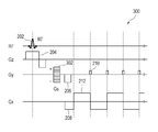
일 실시예에서, EPI 시퀀스(200)는, 도 2에 도시된 바와 같이, 90°RF 여기 (radio frequency excitation) 펄스(202)를 RF신호로서 RF코일을 통해 전달할 수 있다. 일 실시예에서, 90°RF 여기 펄스(202)는 소정의 대상에 대해 이미지 평면에 수직하는 방향으로 가해질 수 있다.In one embodiment, the
일 실시예에서, EPI 시퀀스(200)는 소정의 대상에 대해 서로 직교하는 세 개의 좌표계를 갖는 경사자계 자기장을 MRI 장치의 경사자계 코일을 통해 가할 수 있다. 도 2에 도시한 바와 같이, 서로 직교하는 세 개의 좌표계는 소정의 대상의 이미지 평면(imaging plane)에 수직인 축(Gz)과, 이미지 평면에 평행하면서 서로 직교하는 축(Gy) 및 축(Gx)으로 구성될 수 있다. In one embodiment, the
일 실시예에서, EPI 시퀀스(200)는, 축(Gz) 방향을 따라, EPI 영상을 구성하기 위해 슬라이스(slice)를 선택하는 슬라이스 선택적 자기장 경사자계(slice selective magnetic field gradient)(204)를 가할 수 있다. 일 실시예에서, 슬라 이스 선택적 자기장 경사자계(204)는, 도 2에 도시된 바와 같이 펄스 형상을 가질 수 있다. 일 실시예에서, 슬라이스 선택적 자기장 경사자계(204)는 90°RF 여기 펄스(202)와 동시에 소정의 대상에 대해 가해질 수 있다. In one embodiment, the
일 실시예에서, EPI 시퀀스(200)는, 축(Gy) 방향을 따라, 여기된 세포들이 공간적으로 인코딩하기 위한 위상 인코딩 경사자계(206, 210)를 가할 수 있다. 도 2에 도시된 바와 같이, 위상 인코딩 경사자계(206, 210)는, 90°RF 여기 펄스(202) 및 슬라이스 선택적 자기장 경사자계(204)가 가해진 후 일정 시간 간격을 두고 가해질 수 있다. 또한, 위상 인코딩 경사자계(210)는, 도 2에 도시된 바와 같이, 위상 인코딩 경사자계(206)가 가해진 후 일정 시간 간격을 두고 가해질 수 있다. 일 실시예에서, 위상 인코딩 경사자계(210)는, 도 2에 도시된 바와 같이, 일정한 주기를 갖는 EPI 블립(blip)들을 포함할 수 있다. In one embodiment, the
일 실시예에서, EPI 시퀀스(200)는, 축(Gx) 방향을 따라, 위상 이동 경사자계(phase shift gradient)(208) 및 k-공간(k-space)을 스캔하기 위한 리드 아웃 경사자계(readout gradient)(212)를 가할 수 있다. 도 2에 도시된 바와 같이, 위상 이동 경사자계(phase shift gradient)(208) 및 리드아웃 경사자계(readout gradient)(212)는 90°RF 여기 펄스(202) 및 슬라이스 선택적 자기장 경사자계(204)가 가해진 후 일정한 시간 간격을 두고 가해질 수 있다. 또한, 리드아웃 경사자계(readout gradient)(212)는 주기성을 갖는 펄스 파형을 포함할 수 있으며 위상 이동 경사자계(phase shift gradient)(208)가 가해진 후 일정 기간 동안 반복적으로 가해질 수 있다. In one embodiment, the
도 2에 도시된 바와 같이, 위상 인코딩 경사자계(206) 및 위상 이동 경사자계(208)는 각각 축(Gy) 및 축(Gx)을 따라서 동시에 가해질 수 있다. 또한, 도 2에 도시된 바와 같이, 위상 인코딩 경사자계(210) 및 리드아웃 경사자계(212)는 동일한 주기를 가지고 동시에 가해질 수 있다. EPI 시퀀스(200)에서는, 이와 같이 위상 인코딩 경사자계(210) 및 리드아웃 경사자계(212)를 가하여 획득되는 데이터로 k-공간(k-space)을 채움으로써 EPI 영상이 획득된다.As shown in FIG. 2, the phase encoding gradient
도 2에서는, 서로 직교하는 세 개의 좌표계가 소정의 대상의 이미지 평면(imaging plane)에 수직인 축(Gz)과, 이미지 평면에 평행하면서 서로 직교하는 축(Gy) 및 축(Gx)으로 구성된 것으로 도시하고 있으나, MRI 장치의 경사자계 코일을 통하여 가해지는 공간적으로 분리된 경사자계 자기장은 이와 같은 좌표계에 한정되지 않으며 다른 좌표계를 갖는 다양한 실시예로 변형될 수 있음을 알아야 한다. 또한, EPI 시퀀스에 있어서 각 경사자계의 파형 및 경사자계가 가해지는 시점은 도 2에 도시된 바에 한정되지 않으며 다양하게 변형될 수 있음을 알아야 한다.In FIG. 2, three coordinate systems orthogonal to each other consist of an axis Gz perpendicular to an image plane of a given object, an axis Gy and an axis Gx parallel to and perpendicular to the image plane. Although illustrated, the spatially separated gradient magnetic field applied through the gradient magnetic coil of the MRI apparatus is not limited to such a coordinate system, and it may be modified in various embodiments having different coordinate systems. In addition, it should be noted that the waveform and the timing of applying the gradient magnetic field of each gradient magnetic field in the EPI sequence are not limited to those shown in FIG. 2 and may be variously modified.
이와 같은 EPI 영상을 획득함에 있어서 외부의 비공조(Off-resonance) 현상이 존재하는 경우, 위치 r(x,y) 및 시간 t에서의 공명주파수![]()
![]()
![]()
![]()
수학식 1에서, ![]()
![]()
![]()
![]()
![]()
![]()
![]()
![]()
이 같은 시퀀스에 독립적인 파라미터들의 상호 작용에 의한 영향들은 소용돌이 전류(eddy current)의 영향과 같이 시간에 무관(time-independent)할 수 있다. 따라서, 데이터가 획득되는 동안 축적된 데이터에 있어서 위치 r(x,y) 및 시간 t에서의 위상 이동량 ![]()
![]()

수학식 2에 있어서, T는 k공간에서 하나의 라인을 획득하는데 걸리는 시간을 나타내고, ky는 위상 인코딩 방향으로의 좌표를 나타내고, ky0는 가장 처음 획득된 위상 인코딩 라인의 ky의 좌표를 나타낸다. 또한, ![]()
![]()
일반적인 EPI 시퀀스(standard EPI sequence)를 이용하여 획득된 신호 ![]()
![]()

수학식 3에 있어서, kx는 EPI 리드 아웃을 나타내고, ky는 EPI 블립을 나타내고, ![]()
![]()
EPI 영상이 획득된 소정의 대상에 대해 PSF(point spread function) 기법을 이용하여 3차원 주파수공간(3D k-space) 데이터를 생성한다(S102). PSF 기법은, 도 3에 도시된 바와 같은 PSF 시퀀스(300)를 통해 실행될 수 있다. In operation S102, 3D k-space data is generated using a point spread function (PSF) technique for a predetermined object from which an EPI image is obtained. The PSF technique may be implemented via the
도 3에 도시된 PSF 시퀀스(300)는 도 2에 도시된 EPI 시퀀스(200)를 기초로 구성되어 있다. 따라서, PSF 시퀀스(300)는 도 2에 도시된 EPI 시퀀스(200)와 마찬가지로 90°RF 여기 펄스(202)를 포함하며, 축(Gz)을 따라서 가해지는 슬라이스 선택적 자기장 경사자계(204), 축(Gy)을 따라서 가해지는 위상 인코딩 경사자계(206, 210) 및 축(Gx)을 따라서 가해지는 위상 이동 경사자계(208) 및 리드아웃 경사자계(212)를 포함할 수 있다. The
PSF 시퀀스(300)에 있어서, 축(Gy)을 따라서 가해지는 경사자계는 위상 인 코딩 프리와인드 경사자계(phase encoding prewinder gradient s: Gs)(302)를 더 포함할 수 있다. 일 실시예에서, 인코딩 프리와인드 경사자계(302)는 위상 인코딩 경사자계(206,210)에 앞서 가해질 수 있다. 일 실시예에서, 위상 인코딩 프리와인드 경사자계(302)는, 위상 인코딩 스텝(step)이 단계적으로 변화해 가면서 반복적으로 가해지도록, 서로 다른 크기를 갖는 복수 개의 위상 인코딩 스텝(step)을 포함할 수 있다. In the
도 3에 도시된 PSF 시퀀스(300)는 하나의 예시에 불과하며, PSF 시퀀스(300)는 다른 형태로도 변형될 수 있음을 알아야 한다. 예를 들어, PSF 시퀀스(300)는 도 2에 도시된 EPI 시퀀스(200)와는 다른 형태의 EPI 시퀀스를 기초로 구성될 수 있다.It is to be understood that the
이와 같이 실행되는 PSF 시퀀스(300)에 의해 3차원 주파수 공간 데이터(400)를 생성할 수 있다. 일 실시예에서, 3차원 주파수 공간 데이터(400)는, 하나의 주파수 인코딩 차원(kx)과 두 개의 독립적인 위상 인코딩 차원(ky,ks)을 갖는 3차원 주파수 공간(kx,ky,ks)에 구성될 수 있다. 일 실시예에서, 3차원 주파수 공간 데이터(400)는 복수개의 2차원 주파수공간 데이터(4101 내지 410n)를 포함할 수 있다. 도 4에 도시된 바와 같이, 복수개의 2차원 주파수공간 데이터(4101 내지 410n)는 2차원(kx,ky)을 가질 수 있으며, ks방향을 따라 3차원 주파수 공간(kx,ky,ks)을 채워 3차원 주파수 공간 데이터(400)를 형성할 수 있다. 일 실시예에서, 각 2차원 주파 수공간 데이터(4101 내지 410n)는 PSF 시퀀스(300)의 위상 인코딩 프리와인더 경사자계(Gs)에 포함된 각의 스텝이 실행됨에 따라 생성될 수 있다. The three-dimensional
3차원 주파수 공간(kx,ky,ks)을 갖는 3차원 주파수 공간 데이터(400) S(kx,ky,ks)는 수학식 4와 같은 수식으로 표현할 수 있다. Three-dimensional frequency space (k x, k y, k s) a three-dimensional frequency space data (400) S (k x, k y, k s) with can be expressed as a formula, such as Equation (4).

수학식 4에서, kx는 EPI 리드 아웃을 나타내고, ky는 EPI 블립을 나타내고, ks는 위상 인코딩 스텝을 나타낸다. 또한, ![]()
![]()
다음으로, PSF 시퀀스(300)에 의해 획득한 3차원 주파수공간 데이터(400)에 대해 도메인 변환을 실행하여 공간 도메인을 갖는 3차원 PSF 데이터(500)를 생성한다(S104). 일 실시예에서, 3차원 주파수공간 데이터(400)에 대해 3차원 푸리에 변환을 실행하여 3차원 PSF 데이터(500)를 생성할 수 있다. Next, domain transformation is performed on the 3D
도 5는 3차원 PSF 데이터(500)의 일례를 도시한다. 도 5에 도시된 바와 같이, 3차원 PSF 데이터(500)는 3차원 공간(x,y,s)으로 구성될 수 있으며, 왜곡된 차원(x,y)과 왜곡되지 않은 차원(x,s)을 포함하도록 구성될 수 있다.5 shows an example of three-
수학식 5에서와 같이, 수학식 4에 나타낸 3차원 주파수 공간 데이터(400)인 S(kx,ky,ks)에 대해 주파수 공간(kx,ky,ks)에 대한 푸리에 변환을 실행하면 영상 신호 강도 를 획득할 수 있다. As in Equation 5, Fourier transform for frequency space (k x , k y , k s ) for S (k x , k y , k s ), which is the three-dimensional

영상 신호 강도 ![]()
![]()
![]()
![]()
![]()
![]()

일 실시예에서, 3차원 PSF 데이터(500)를 생성한 후에 3차원 PSF 데이터(500)에 발생된 나이퀴스트유령인공물(Nyquist ghost artifact)을 제거하기 위한 위상 보정(phase correction)을 실행할 수 있다. 또한, 일 실시예에서, 비균일 샘플링에 대한 리그라이딩(regriding)을 실행한다.In one embodiment, after generating the
다음으로, 3차원 PSF 데이터(500)를 2차원 평면에 맵핑하여 2차원 PSF 데이터(600)를 생성한다(S106). Next, the two-
일 실시예에서, 2차원 PSF 데이터(600)가 ys차원을 갖도록 3차원 PSF 데이터(500)는 ys평면에 맵핑될 수 있다. 도 6a는, 외부 자기장 비균일성 및 국소 자 화율 효과로 인해 왜곡된 3차원 PSF 데이터(500) 및 3차원 PSF 데이터(500)로부터 획득한 2차원 PSF 데이터(600)를 도시한다. 도 6a에 도시된 바와 같이, 3차원 PSF 데이터(500)로부터 획득한 하나의 2차원 PSF 데이터(600)는 3차원 PSF 데이터(500) 중 동일한 ys평면에 맵핑된 복수개의 픽셀(이하, 'PSF')을 포함할 수 있다. 일 실시예에서, 3차원 PSF 데이터(500)를 x축을 따라 서로 다른 복수개의 ys평면에 맵핑하여 복수개의 2차원 PSF 데이터(600)를 획득할 수 있다. In one embodiment, the three-
도 6a에 있어서, 2차원 PSF 데이터(600)에 표시된 기준선(602)은 영상 왜곡이 발생하지 않았을 경우 2차원 PSF 데이터(600)의 PSF들이 ys평면에 배열되는 위치를 나타낸다. 일 실시예에서, 기준선(602)은 ys평면에서 기울기가 "1"이고 원점을 지나는 직선일 수 있다. In FIG. 6A, the
일 실시예에서, 2차원 PSF 데이터(600)의 PSF들은 기준선(602)로부터 이탈하도록 배열될 수 있다. 예를 들어, 도 6a에 도시된 바와 같이, 2차원 PSF 데이터(600)에 포함된 복수개의 PSF 중 ys평면에서 원점에 가까이 배치된 PSF들 및 s값 및 y값이 큰 PSF들은 국소 자화율의 영향(local susceptibility effect)으로 인하여 기준선(602)로부터 이탈하여 배열될 수 있다. In one embodiment, the PSFs of the two-
도 6a의 PSF 완만화 영역(604)은 PSF들이 기준선(602)로부터 이탈하여 배열된 영역을 나타내며, 도 6b는 PSF 완만화 영역(604)을 확대하여 도시한 것이다. 도 6b에 도시된 바와 같이, 2차원 PSF 데이터(600)의 일부 PSF들(622)은 기준선(602)을 따라 배열되나 s값 및 y값이 큰 PSF들은 국소 자화율의 영향으로 인하여 기준선(602)로부터 이탈하여 배열될 수 있다. 또한, 도 6b에 도시된 바와 같이, PSF 완만화 영역(604)에서는 본래 하나의 픽셀을 차지하는 PSF가 복수개의 PSF로 퍼져 복수개의 픽셀에 배치될 수 있다. 예를 들어, PSF(624)는, 국소 자화율의 영향으로 인하여 기준선(602)로부터 이탈하여 배치될 수 있으며, 블러링 현상이 발생하여 두 개의 픽셀로 퍼지면서 PSF(624)와는 별개의 픽셀을 차지하는 PSF(624a)가 생성될 수 있다. 마찬가지로, PSF(626)도 국소 자화율의 영향(local susceptibility effect)으로 인하여 기준선(602)로부터 이탈하여 배치되며, 블러링 현상으로 인하여 두 개의 픽셀로 퍼지면서 PSF(626)와는 별개의 픽셀을 차지하는 PSF(626a,626b)가 생성될 수 있다.The PSF
이와 같은 블러링 현상은 이하의 수학식 7 및 8을 이용하여 설명할 수 있다. 수학식 7은, 안정된 비공조(Off-resonance)의 경우를 가정하였을 때 ys평면에서의 대각선 방향으로부터 수평 방향, 즉 왜곡된 차원으로 PSF 정점(peak)이 이동한 값에 관한 함수 ![]()
![]()
![]()
![]()
![]()
![]()
![]()
![]()
그러나 3차원 PSF 데이터(500)에 속한 하나 이상의 PSF는 신호 감쇄 및 소용돌이 전류의 영향 등으로 수학식 8의δ함수로부터 이탈할 수 있다. 따라서, 왜곡된 3차원 PSF 데이터(500)으로부터 획득된 2차원 PSF 데이터(600)는 기준선(602)을 이탈하여 넓게 퍼진 PSF를 포함하게 된다.However, one or more PSFs belonging to the
다음으로, 2차원 PSF 데이터(600)를 기초로 3차원 PSF 데이터(500)의 왜곡 정도를 나타내는 PSF 맵핑 데이터를 산출하여 2차원 PSF 데이터(600)에 대한 이동맵을 생성할 수 있다(S108). 일 실시예에서, PSF 맵핑 데이터는 2차원 PSF 데이터(600)에 포함된 복수의 PSF가 기준선(602)을 벗어난 정도를 나타내는 PSF 이동량을 계산함으로써 산출될 수 있다. Next, PSF mapping data indicating the degree of distortion of the
일 실시예에서, PSF 맵핑 데이터는 ys평면을 갖는 2차원 PSF 데이터(600)를 왜곡된 차원인 y차원으로 추출하는 변동(variable) PSF 맵핑 기법을 이용하여 획득된 변동 PSF 맵핑 데이터일 수 있다. 도 7a는 왜곡된 EPI 영상(700)에 대한 변동 PSF 맵핑 기법의 적용을 설명하는 도면이고, 도 7b는 변동 PSF 맵핑 기법을 이용하여 획득한 이동맵(702)을 도시한다. 일 실시예에서, 변동 PSF 맵핑 기법은 2차원 PSF 데이터(600)에 포함된 PSF들을 y축으로 맵핑하여 기준선(602)으로부터 y축 방향으로 이동한 이동량을 측정하여 변동 PSF 맵핑 데이터를 산출할 수 있다. 이 경우 하나의 2차원 PSF 데이터(600)에 대해 산출된 변동 PSF 맵핑 데이터는 y차원을 갖게 된다. In one embodiment, the PSF mapping data may be variable PSF mapping data obtained using a variable PSF mapping technique that extracts two-
일 실시예에서, 변동 PSF 맵핑 데이터에 기초하여, 왜곡된 영상이 존재하는 부분을 나타내는 왜곡된 영상의 마스크(mask) 영역(이하, '왜곡 영상 마스크 영 역')에서 이동맵(702)을 생성할 수 있다. 일 실시예에서, 변동 PSF 맵핑 기법에서 이용하는 마스크는 xy평면 상에 배치되므로 이동맵(702)도 xy차원을 가질 수 있다. 도 7b에 도시된 바와 같이, 하나의 2차원 PSF 데이터(600)에 대한 산출된 변동 PSF 맵핑 데이터를 이용하면 이동맵(702) 상에서 점선으로 나타낸 바와 같이 임의의 x좌표에서 y축 방향으로 왜곡 영상 마스크 영역의 안쪽을 채워나갈 수 있다. 따라서 복수의 2차원 PSF 데이터(600)에 대한 변동 PSF 맵핑 데이터를 이용하면 x축 방향으로 왜곡 영상 마스크 영역의 안쪽을 채워나갈 수 있어 xy차원을 갖는 이동맵(702)을 생성할 수 있다. 일 실시예에서, 왜곡 영상 마스크 영역의 윤곽이 채워진 이동맵(702)에 대하여 피팅(fitting) 및 필터링 과정을 더 실행할 수 있다.In one embodiment, based on the variable PSF mapping data, the
다음으로, 이동맵(702)을 왜곡된 EPI 영상에 적용하여 보정된 영상을 획득한다(S110). 일 실시예에서, 보정된 영상은 이동맵(702)을 왜곡된 EPI 영상의 크기(magnitude) 데이터에 적용함으로써 획득될 수 있다. 일 실시예에서, 이동맵(702)은 왜곡된 EPI 영상의 절대값(magnitude)에 적용함으로써 보정된 영상을 얻을 수 있다.Next, the moving
이하에서는, 도 7a 및 도 7b에서 설명한 변동 PSF 맵핑 기법의 영상 보정 효과를 고정(fixed) PSF 맵핑 기법과 비교하여 설명한다. Hereinafter, the image correction effect of the variable PSF mapping technique described with reference to FIGS. 7A and 7B will be described in comparison with a fixed PSF mapping technique.
도 8a는 왜곡된 EPI 영상(800)에 대한 고정 PSF 맵핑 기법의 적용을 설명하는 도면이며, 도 8b는 고정 PSF 맵핑 기법을 실행하여 획득한 이동맵(802)을 도시한다. 도 8a에 도시된 바와 같이, 고정 PSF 맵핑 기법에서는 ys평면을 갖는 2차원 PSF 데이터(600)를 왜곡되지 않은 차원인 s차원으로 추출하여 고정 PSF 맵핑 데이 터를 획득한다. 예를 들어, 고정 PSF 맵핑 데이터는 2차원 PSF 데이터(600)에 포함된 PSF들을 s축으로 맵핑하여 PSF들이 기준선(602)으로부터 s축 방향으로 이동한 이동량을 측정하여 산출된다. 이와 같이 산출된 고정 PSF 맵핑 데이터는, 이하에서 자세히 설명하는 바와 같이, 변동 PSF 맵핑 데이터보다 PSF들의 이동과 관련된 정보를 적게 포함한다.FIG. 8A illustrates the application of the fixed PSF mapping technique to the
도 9a 및 도 9b는, 도 6b에 도시한 2차원 PSF 데이터(600)에 대하여 고정 PSF 맵핑 기법을 이용하여 생성한 이동맵(900a)과 변동 PSF 맵핑 기법을 이용하여 생성한 이동맵(900b)을 각각 도시한다. 앞서 설명한 바와 같이, 2차원 PSF 데이터(600)는 기준선(602)을 이탈하지 않고 배열된 PSF들(622)과 기준선(602)에서 이탈하여 배열된 PSF들 (624,626)을 포함한다. 또한, 2차원 PSF 데이터(600)는 본래 한 개의 픽셀을 차지하던 PSF들(624,626)이 여러 픽셀로 퍼지면서 발생된 PSF들(624a,626a,626b)을 포함한다. 9A and 9B illustrate a
도 9a에 도시된 바와 같이, 고정 PSF 맵핑 기법의 경우, 2차원 PSF 데이터(600)를 왜곡되지 않은 차원인 s축 방향으로 맵핑하여 PSF의 이동량을 측정하므로, PSF들(624,626)의 이동량은 측정되나 PSF(604a,606a,606b)의 이동량은 측정되지 않는다. 따라서, 고정 PSF 맵핑 데이터에는 PSF들(624,626)의 이동은 반영되나 PSF(604a,606a,606b)의 이동은 반영되지 않는다. 따라서, 고정 PSF 맵핑 데이터를 기초로 산출된 이동맵(900a)은 블러링 현상을 정확히 반영할 수 없다. As shown in FIG. 9A, in the case of the fixed PSF mapping technique, the amount of movement of the
반면, 변동 PSF 맵핑 기법에서는, 도 9b에 도시된 바와 같이, PSF 데이터(600)를 왜곡된 차원인 y축 방향으로 맵핑하여 PSF의 이동량을 측정하므로, PSF 들(624,626)의 이동뿐만 아니라 PSF(604a,606a,606b)의 이동이 측정될 수 있다. 따라서, 변동 PSF 맵핑 데이터에는 PSF들(624,626)의 이동 및 PSF(604a,606a,606b)의 이동이 모두 반영되게 된다. 도 9c에 도시한 바와 같이, 기준선(602)이 ys평면에서 원점을 지나고 기울기가 "1"인 직선이면, 기준선(602)을 이탈한 PSF(902)에 대하여 s방향으로 이동한 거리를 나타내는 길이(LA)와 y방향으로 이동한 거리를 나타내는 길이(LB)는 항상 동일하다. 따라서, PSF가 기준선으로부터 y방향으로 이동한 값을 측정할 경우 y방향으로 이동한 값도 함께 측정될 수 있다. 따라서 변동 PSF 맵핑 데이터는 고정 PSF 맵핑 데이터가 포함한 정보를 포함함과 동시에 둘 이상의 픽셀로 늘어난 PSF의 이동량에 관한 정보도 포함하고 있으므로 고정 PSF 맵핑 데이터에 비해 더 많은 정보를 포함할 수 있다. On the other hand, in the variable PSF mapping technique, as shown in FIG. 9B, since the
이와 같이 변동 PSF 맵핑 데이터는 고정 PSF 맵핑 데이터보다 더 많은 PSF의 이동에 관한 정보를 포함할 수 있으므로, 변동 PSF 맵핑 데이터를 기초로 산출된 이동맵(900b)은 고정 PSF 맵핑 데이터를 기초로 산출된 이동맵(900a)에 비해 블러링 현상을 보다 정확히 반영할 수 있다. 도 7b 및 도 8b에 도시된 바와 같이, 도 7b에 도시된 변동 PSF 맵핑 기법을 통해 생성된 이동맵(702)은 도 8b에 도시된 고정 PSF 맵핑 기법을 통해 생성된 이동맵(802)보다 블러링 현상을 보다 정확히 반영한다. 따라서, 변동 PSF 맵핑 기법을 이용하면 고정 PSF 맵핑 기법을 이용하는 경우보다 EPI 영상 보정을 더욱 정확히 실행할 수 있다.As such, since the variable PSF mapping data may include information about the movement of more PSFs than the fixed PSF mapping data, the
이하에서는, 도 10을 이용하여 고정 PSF 맵핑 기법과 변동 PSF 맵핑 기법에 있어서 혈류 이동에 의한 유령인공물(ghost by flow artifact)이 미치는 영향을 설명한다. Hereinafter, the effects of ghost by flow artifacts due to blood flow in the fixed PSF mapping method and the variable PSF mapping method will be described with reference to FIG. 10.
초고자장에서의 영상에서, 고해상도 영상 획득 시에 일반적으로 TE(echo time)가 늘어나게 된다. 하지만, TE(time echo)가 길어지게 되면, 혈류이동에 따른 고스트가 3차원 PSF 데이터(1000)에 발생하게 된다. 이와 같이 영상에 혈류 이동에 따른 고스트가 포함된 3차원 PSF 데이터(1000) 경우에, 2차원 PSF 데이터(1002)에는, 확대된 2차원 PSF 데이터(1002b)에 도시된 바와 같이 혈류 이동에 따른 고스트 PSF(1002a)가 포함될 수 있다. In an image in an ultra high field, an echo time (TE) is generally increased when a high resolution image is acquired. However, when the TE (time echo) becomes longer, ghost due to blood flow is generated in the
표 1은, 왜곡된 y차원과 왜곡되지 않은 s차원에 있어서 원 PSF와 고스트 PSF의 위치 및 강도를 비교한 것이다.Table 1 compares the positions and intensities of the original PSF and the ghost PSF in the distorted y-dimension and the undistorted s-dimension.
표 1을 참고하면, 원 PSF와 고스트 PSF가 왜곡되지 않은 s차원으로 맵핑하는 경우에는 원 PSF와 다른 위치의 원 PSF로부터 기인한 고스트 PSF가 같은 선상에 위치하게 된다. 원 PSF의 고스트 PSF가 s차원을 따라 이동하여 나타나기 때문에, s 차원의 한 축에서 보면, 그 축 상에서 보여지는 원 PSF와 같은 축에서 보여지는 고스트 PSF는 다른 위치에서의 원 PSF에서부터 기인한 것이다. 따라서, 같은 선상에서 보여지는 원 PSF가 다른 위치의 원 PSF로 부터 기인한 고스트 PSF보다 항상 크지 않고, 그 위치에 따라 다르게 된다. 만약 같은 선상에 위치한 원 PSF의 강도가 다른 위치의 원 PSF로 부터 기인한 고스트 PSF의 강도보다 작게 되면, 맵핑 시 원 PSF의 이동을 맵핑하는 것이 아니라 보다 높은 강도를 가진 고스트 PSF의 이동을 맵핑하게 된다. 따라서, 고스트 PSF(1002a)가 포함된 2차원 PSF 데이터(1002)에 대해 s차원에서의 고정 PSF 맵핑 기법을 이용하여 이동맵(1006)을 산출할 경우에는, 이동맵(1006)에는 고스트 PSF 데이터의 이동이 반영되므로, 고스트가 포함된 영상에서는 원 PSF 데이터의 이동을 맵핑할 수 없는 문제점이 있다.Referring to Table 1, when the original PSF and the ghost PSF are mapped to the s-dimensional which is not distorted, the ghost PSF originating from the original PSF and the original PSF at a different position is positioned on the same line. Since the ghost PSF of the original PSF appears to move along the s dimension, in one axis of the s dimension, the ghost PSF seen in the same axis as the original PSF seen on that axis originates from the original PSF at another position. Thus, the original PSF seen on the same line is not always larger than the ghost PSF resulting from the original PSF at other positions, and varies depending on the position. If the strength of the original PSF located on the same line is less than the strength of the ghost PSF resulting from the original PSF at the other location, then the mapping of the higher PSN is not mapped. do. Therefore, when the
표 1과 같이, 왜곡된 y차원에서 맵핑하는 경우, 원 PSF와 고스트 PSF가 같은 선상에서 존재하며, 원 PSF는 고스트 PSF 보다 항상 높은 강도를 갖는다. 따라서, 고스트 PSF(1002a)가 포함된 2차원 PSF 데이터(1002)에 대해 왜곡된 차원에서의 PSF 맵핑은, 고스트 PSF에 의한 이동은 반영되지 않고 보다 높은 강도를 갖는 원 PSF의 이동이 반영된 이동맵(1004)을 얻을 수 있다. 따라서, 고정 PSF 맵핑 데이터는 혈류 이동에 따른 유령인공물에 의한 영향을 받지 않기 때문에 보다 정확한 EPI 영상 보정이 가능하다. As shown in Table 1, when mapping in the distorted y-dimension, the original PSF and the ghost PSF exist on the same line, and the original PSF always has a higher intensity than the ghost PSF. Therefore, the PSF mapping in the distorted dimension for the two-
이하에서는, 도 11 및 도 12를 참조하여 멀티샷을 통해 얻어지는 왜곡된 EPI 영상의 보정 방법을 설명한다.Hereinafter, a method of correcting a distorted EPI image obtained through multishot will be described with reference to FIGS. 11 and 12.
도 11은, 하나의 샷을 통해 얻어지는 이미지의 처리 과정을 도시한 도면이다.11 is a diagram illustrating a process of processing an image obtained through one shot.
먼저, 도 1을 참조하여 설명한 바와 같이, 소정의 대상에 대하여 EPI 시퀀스를 실행하여 EPI 영상을 생성하며(S1200), EPI 영상을 획득한 동일한 대상에 대해 PSF(point spread function) 시퀀스를 실행하여 3차원 주파수공간(3D k-space)데이터(1100)를 생성한 후, 도 11에 도시된 바와 같이 3차원 주파수공간 데이터를 홀(odd) 주파수공간 데이터(1102a) 및 짝(even) 주파수 공간 데이터(1102b)로 분리한다(S1202). First, as described with reference to FIG. 1, an EPI sequence is generated by executing an EPI sequence with respect to a predetermined object (S1200), and a PSF (point spread function) sequence is executed with respect to the same object from which the EPI image is obtained. After generating the 3D k-
홀 주파수공간 데이터(1102a) 및 짝 주파수 공간 데이터(1102b)의 도메인을 주파수 도메인에서 공간 도메인으로 변환하여 3차원 홀 PSF 데이터(1104a) 및 3차원 짝 PSF 데이터(1104b)를 생성한다(S1204). 일 실시예에서, 홀 주파수공간 데이터(1102a) 및 짝 주파수 공간 데이터(1102b)의 도메인 변환을 위해 3차원 퓨리에 변환을 실행할 수 있다. The domains of the hole frequency
3차원 홀 PSF 데이터(1104a) 및 3차원 짝 PSF 데이터(1104b)에 대해 영상 속에 포함될 수 있는 나이퀴스트유령인공물을 제거하기 위한 위상 보정(phase correction)을 실행하여 나이퀴스트유령인공물이 존재하지 않는 3차원 홀 PSF 데이터(1106a) 및 3차원 짝 PSF 데이터(1106b)를 생성할 수 있다(S1208). 나이퀴스트유령인공물을 제거하기 위한 위상 보정은 종래에 알려진 모든 위상 보정 방법에 의해 달성될 수 있음을 알아야 할 것이다.The Nyquist ghost artifact is not present by performing phase correction to remove the Nyquist ghost artifact that may be included in the image for the 3D
다음으로, 도 1을 참조하여 설명한 PSF 맵핑 단계(S104)에 대응되는 PSF 맵핑 단계(S1206), PSF 맵핑 데이터 생성 및 이동맵 생성 단계(S108)에 대응되는 PSF 맵핑 데이터 생성 및 이동맵 생성 단계(S1208)를 차례대로 실행하여, 왜곡이 보정된 홀 보정 영상(1108a) 및 짝 보정 영상(1108b)을 생성한다(S1210). Next, the PSF mapping data corresponding to the PSF mapping step S104 described with reference to FIG. 1 (S1206), the PSF mapping data generation and the moving map generation step S108, and the PSF mapping data generation and moving map generation steps ( S1208 is executed in order to generate a hole corrected
홀 보정 영상(1108a) 및 짝 보정 영상(1108b)을 이용하여 EPI 영상에 각각 적용 시킨 후 영상 도메인에서 합침으로써 보정된 EPI 영상(1110)을 획득한다(S1212).The corrected
이와 같이, 다채널 RF 코일이 이용되는 경우에 있어서 3차원 주파수공간 데이터를 홀(odd) 주파수 공간 데이터와 짝(even) 주파수 공간 데이터로 분리하여 처리할 경우, 홀(odd) 영상과 짝(even) 영상으로 분리됨에 따라 영상이 겹쳐 보이는 앨리어싱(aliasing) 현상이 발생하나, 이러한 앨리어싱 현상을 기존의 병렬(parallel) 기법을 이용하여 풀어냄으로써 나이퀴스트유령인공물을 제거할 수 있다. 또한, 홀(odd) 영상과 짝(even) 영상 각각에 대하여 생성된 이동맵을 홀(odd) 영상과 짝(even) 영상에 적용함으로써 자기장에 의한 왜곡도 보정할 수 있다. 따라서, 나이퀴스트유령인공물의 제거 및 왜곡의 보정을 동시에 해결할 수 있다.As described above, when multi-channel RF coils are used, when three-dimensional frequency space data is processed by being divided into odd frequency space data and even frequency space data, the odd image and the even image are even. As the image is separated into an image, an aliasing phenomenon in which the image overlaps occurs, but the Nyquist ghost artifact can be removed by solving the aliasing phenomenon using a conventional parallel technique. In addition, distortion by the magnetic field may also be corrected by applying a moving map generated for each of the odd image and the even image to the odd image and the even image. Therefore, the removal of the Nyquist ghost artifacts and the correction of the distortion can be solved simultaneously.
도 1은, 일 실시예에 따른, EPI 시퀀스를 실행하여 획득한 영상의 영상 보정 방법을 도시한 순서도이다.1 is a flowchart illustrating a method of correcting an image of an image acquired by executing an EPI sequence, according to an exemplary embodiment.
도 2는, EPI 시퀀스의 일 실시예를 도시한 도면이다.2 is a diagram illustrating an embodiment of an EPI sequence.
도 3은, PSF 시퀀스의 일 실시예를 도시한 도면이다.3 is a diagram illustrating an embodiment of a PSF sequence.
도 4는, PSF 시퀀스를 실행하여 획득한 3차원 주파수 공간 데이터의 일 실시예를 도시한 도면이다.4 is a diagram illustrating an embodiment of three-dimensional frequency spatial data obtained by executing a PSF sequence.
도 5는, 3차원 PSF 데이터의 일례를 도시한다.5 shows an example of three-dimensional PSF data.
도 6a는 2차원 PSF 데이터의 일 실시예를 도시하고, 도 6b는 도 6a에 도시된 2차원 PSF 데이터에서의 PSF 완만화 영역을 도시한다.FIG. 6A illustrates one embodiment of two-dimensional PSF data, and FIG. 6B illustrates a PSF gentle area in the two-dimensional PSF data shown in FIG. 6A.
도 7a는 왜곡된 EPI 영상에 대한 변동 PSF 맵핑 기법의 적용을 설명하는 도면이고, 도 7b는 변동 PSF 맵핑 기법을 이용하여 획득한 이동맵을 도시하는 도면이다.FIG. 7A is a diagram illustrating the application of the variable PSF mapping technique to the distorted EPI image, and FIG. 7B is a diagram illustrating a movement map obtained by using the variable PSF mapping technique.
도 8a는 왜곡된 EPI 영상에 대한 고정 PSF 맵핑 기법의 적용을 설명하는 도면이고, 도 8b는 고정 PSF 맵핑 기법을 실행하여 획득한 이동맵을 도시한다.FIG. 8A illustrates the application of the fixed PSF mapping technique to the distorted EPI image, and FIG. 8B illustrates a movement map obtained by executing the fixed PSF mapping technique.
도 9a 및 도 9b는, 도 6b에 도시한 2차원 PSF 데이터(600)에 대하여 고정 PSF 맵핑 기법을 이용하여 생성한 이동맵과 변동 PSF 맵핑 기법을 이용하여 생성한 이동맵을 각각 도시하며, 도 9c는 PSF의 이동 길이와 이동 방향의관계를 나타내는 도면이다.9A and 9B illustrate a movement map generated by using a fixed PSF mapping technique and a movement map generated by using a variable PSF mapping technique, respectively, for the two-
도 10은, 혈류이동에 의한 유령인공물이 고정 PSF 맵핑 데이터와 변동 PSF 맵핑 데이터에 미치는 영향을 보여주는 도면이다.10 is a view showing the effect of the ghost artifact by blood flow movement on the fixed PSF mapping data and the variable PSF mapping data.
도 11은, 하나의 샷을 통해 얻어지는 이미지의 처리 과정의 일 실시예를 도시한 도면이다.11 is a diagram illustrating an embodiment of a process of processing an image obtained through one shot.
도 12는, 도 11의 이미지 처리 과정을 통하여 EPI 시퀀스를 실행하여 획득한 영상의 영상 보정 방법을 도시한 순서도이다.FIG. 12 is a flowchart illustrating an image correction method of an image acquired by executing an EPI sequence through the image processing process of FIG. 11.
Claims (12)
Applications Claiming Priority (2)
| Application Number | Priority Date | Filing Date | Title |
|---|---|---|---|
| KR20080071379 | 2008-07-22 | ||
| KR1020080071379 | 2008-07-22 |
Publications (2)
| Publication Number | Publication Date |
|---|---|
| KR20100010481A KR20100010481A (en) | 2010-02-01 |
| KR101036046B1 true KR101036046B1 (en) | 2011-05-20 |
Family
ID=42085134
Family Applications (1)
| Application Number | Title | Priority Date | Filing Date |
|---|---|---|---|
| KR1020090061287A KR101036046B1 (en) | 2008-07-22 | 2009-07-06 | EPI Video Distortion Correction Method in MRI Equipment |
Country Status (1)
| Country | Link |
|---|---|
| KR (1) | KR101036046B1 (en) |
Cited By (1)
| Publication number | Priority date | Publication date | Assignee | Title |
|---|---|---|---|---|
| KR102066009B1 (en) | 2018-09-14 | 2020-01-14 | 가천대학교 산학협력단 | Image reconstruction system on medical imaging apparatus using recurrent neural network |
Families Citing this family (6)
| Publication number | Priority date | Publication date | Assignee | Title |
|---|---|---|---|---|
| KR101232368B1 (en) * | 2011-05-27 | 2013-02-13 | 황어진 | Correction apparatus and Correction method of Geometrically Distorted Echo Planar Imaged(EPI) using a Field Inhomogeneity Map |
| KR101875704B1 (en) * | 2011-06-30 | 2018-07-06 | 삼성전자주식회사 | Data processing apparatus, medical imaging system and method for generating diagnosis image |
| KR101330945B1 (en) * | 2011-10-14 | 2013-11-18 | 가천의과학대학교 산학협력단 | Epi image correction method and epi image correction system thereof |
| KR101893383B1 (en) | 2012-03-02 | 2018-08-31 | 삼성전자주식회사 | Apparatus and method for generating ultrasonic image |
| CN105392423B (en) * | 2013-02-01 | 2018-08-17 | 凯内蒂科尔股份有限公司 | The motion tracking system of real-time adaptive motion compensation in biomedical imaging |
| KR102215902B1 (en) * | 2019-09-16 | 2021-02-17 | 한국과학기술원 | Method of correcting an image and apparatuses performing the same |
Citations (4)
| Publication number | Priority date | Publication date | Assignee | Title |
|---|---|---|---|---|
| JPH057571A (en) * | 1990-12-21 | 1993-01-19 | Philips Gloeilampenfab:Nv | Method and device for magnetic resonance formation of image |
| JP2000296120A (en) | 1999-04-13 | 2000-10-24 | Hitachi Medical Corp | Magnetic resonance image diagnostic system |
| KR20010040152A (en) * | 1999-10-22 | 2001-05-15 | 지이 메디컬 시스템즈 글로발 테크놀러지 캄파니 엘엘씨 | Phase distribution measurement method and apparatus, phase correction method and apparatus, and magnetic resonance imaging apparatus |
| KR20010051717A (en) * | 1999-11-17 | 2001-06-25 | 제이 엘. 차스킨, 버나드 스나이더, 아더엠. 킹 | Partial fourier acquisition of mr data over a limited field of view and image reconstruction |
-
2009
- 2009-07-06 KR KR1020090061287A patent/KR101036046B1/en not_active IP Right Cessation
Patent Citations (4)
| Publication number | Priority date | Publication date | Assignee | Title |
|---|---|---|---|---|
| JPH057571A (en) * | 1990-12-21 | 1993-01-19 | Philips Gloeilampenfab:Nv | Method and device for magnetic resonance formation of image |
| JP2000296120A (en) | 1999-04-13 | 2000-10-24 | Hitachi Medical Corp | Magnetic resonance image diagnostic system |
| KR20010040152A (en) * | 1999-10-22 | 2001-05-15 | 지이 메디컬 시스템즈 글로발 테크놀러지 캄파니 엘엘씨 | Phase distribution measurement method and apparatus, phase correction method and apparatus, and magnetic resonance imaging apparatus |
| KR20010051717A (en) * | 1999-11-17 | 2001-06-25 | 제이 엘. 차스킨, 버나드 스나이더, 아더엠. 킹 | Partial fourier acquisition of mr data over a limited field of view and image reconstruction |
Cited By (1)
| Publication number | Priority date | Publication date | Assignee | Title |
|---|---|---|---|---|
| KR102066009B1 (en) | 2018-09-14 | 2020-01-14 | 가천대학교 산학협력단 | Image reconstruction system on medical imaging apparatus using recurrent neural network |
Also Published As
| Publication number | Publication date |
|---|---|
| KR20100010481A (en) | 2010-02-01 |
Similar Documents
| Publication | Publication Date | Title |
|---|---|---|
| KR101036046B1 (en) | EPI Video Distortion Correction Method in MRI Equipment | |
| US9797974B2 (en) | Nonrigid motion correction in 3D using autofocusing with localized linear translations | |
| US9341694B2 (en) | Method and magnetic resonance system for distortion correction in magnetic resonance imaging | |
| In et al. | Highly accelerated PSF-mapping for EPI distortion correction with improved fidelity | |
| JP6037652B2 (en) | Diffusion-weighted magnetic resonance data generation method, magnetic resonance system, and computer-readable storage medium | |
| JP6333293B2 (en) | Metal resistant MR imaging | |
| JP5138043B2 (en) | Magnetic resonance imaging system | |
| US20120002859A1 (en) | Magnetic resonance partially parallel imaging (ppi) with motion corrected coil sensitivities | |
| JP5868160B2 (en) | Magnetic resonance imaging system | |
| JP6243522B2 (en) | Parallel MRI with multi-echo Dixon water-fat separation and B0 distortion correction using regularized detection reconstruction | |
| JP4610611B2 (en) | Magnetic resonance imaging device | |
| JP6367056B2 (en) | Magnetic resonance imaging system | |
| US10241184B2 (en) | EPI ghost correction involving sense | |
| Chung et al. | An improved PSF mapping method for EPI distortion correction in human brain at ultra high field (7T) | |
| US20170212198A1 (en) | Magnetic resonance signal processing method, magnetic resonance signal processing apparatus and magnetic resonance apparatus, and program | |
| JP2004223259A (en) | Measuring and correction of gradient induced cross term magnetic field in epi sequence | |
| KR20200032167A (en) | System and method for strategically acquired tilt echo image | |
| KR101253024B1 (en) | Apparatus and method for restoring 3d image by using magnetic resonance imaging | |
| WO2018184056A1 (en) | Magnetic resonance imaging method and apparatus | |
| KR101773617B1 (en) | Method and MRI device for correcting distortion in an EPI image | |
| JP6936696B2 (en) | Magnetic resonance imaging device and its control method | |
| US20240078636A1 (en) | Image processing apparatus, image processing method, and magnetic resonance imaging apparatus | |
| JP7427616B2 (en) | Magnetic resonance imaging device, image processing device, and phase correction method | |
| EP4332604A1 (en) | Image processing apparatus, image processing method, and magnetic resonance imaging apparatus | |
| JP7614957B2 (en) | Magnetic resonance imaging apparatus and control method thereof |
Legal Events
| Date | Code | Title | Description |
|---|---|---|---|
| A201 | Request for examination | ||
| PA0109 | Patent application |
Patent event code: PA01091R01D Comment text: Patent Application Patent event date: 20090706 |
|
| PA0201 | Request for examination | ||
| PG1501 | Laying open of application | ||
| E701 | Decision to grant or registration of patent right | ||
| PE0701 | Decision of registration |
Patent event code: PE07011S01D Comment text: Decision to Grant Registration Patent event date: 20110223 |
|
| GRNT | Written decision to grant | ||
| PR0701 | Registration of establishment |
Comment text: Registration of Establishment Patent event date: 20110513 Patent event code: PR07011E01D |
|
| PR1002 | Payment of registration fee |
Payment date: 20110513 End annual number: 3 Start annual number: 1 |
|
| PG1601 | Publication of registration | ||
| FPAY | Annual fee payment |
Payment date: 20140306 Year of fee payment: 4 |
|
| PR1001 | Payment of annual fee |
Payment date: 20140306 Start annual number: 4 End annual number: 4 |
|
| FPAY | Annual fee payment |
Payment date: 20160408 Year of fee payment: 6 |
|
| PR1001 | Payment of annual fee |
Payment date: 20160408 Start annual number: 6 End annual number: 6 |
|
| LAPS | Lapse due to unpaid annual fee | ||
| PC1903 | Unpaid annual fee |
Termination category: Default of registration fee Termination date: 20180224 |