KR100960649B1 - Method for Bandwidth Recovery of Communication System - Google Patents
Method for Bandwidth Recovery of Communication System Download PDFInfo
- Publication number
- KR100960649B1 KR100960649B1 KR1020080003073A KR20080003073A KR100960649B1 KR 100960649 B1 KR100960649 B1 KR 100960649B1 KR 1020080003073 A KR1020080003073 A KR 1020080003073A KR 20080003073 A KR20080003073 A KR 20080003073A KR 100960649 B1 KR100960649 B1 KR 100960649B1
- Authority
- KR
- South Korea
- Prior art keywords
- communication
- uplink
- scheduling message
- uplink scheduling
- communication node
- Prior art date
- Legal status (The legal status is an assumption and is not a legal conclusion. Google has not performed a legal analysis and makes no representation as to the accuracy of the status listed.)
- Active
Links
Images


Classifications
-
- H—ELECTRICITY
- H04—ELECTRIC COMMUNICATION TECHNIQUE
- H04L—TRANSMISSION OF DIGITAL INFORMATION, e.g. TELEGRAPHIC COMMUNICATION
- H04L12/00—Data switching networks
- H04L12/28—Data switching networks characterised by path configuration, e.g. LAN [Local Area Networks] or WAN [Wide Area Networks]
- H04L12/2801—Broadband local area networks
-
- H—ELECTRICITY
- H04—ELECTRIC COMMUNICATION TECHNIQUE
- H04W—WIRELESS COMMUNICATION NETWORKS
- H04W72/00—Local resource management
- H04W72/12—Wireless traffic scheduling
- H04W72/1263—Mapping of traffic onto schedule, e.g. scheduled allocation or multiplexing of flows
- H04W72/1268—Mapping of traffic onto schedule, e.g. scheduled allocation or multiplexing of flows of uplink data flows
-
- H—ELECTRICITY
- H04—ELECTRIC COMMUNICATION TECHNIQUE
- H04L—TRANSMISSION OF DIGITAL INFORMATION, e.g. TELEGRAPHIC COMMUNICATION
- H04L5/00—Arrangements affording multiple use of the transmission path
- H04L5/0091—Signalling for the administration of the divided path, e.g. signalling of configuration information
- H04L5/0096—Indication of changes in allocation
-
- H—ELECTRICITY
- H04—ELECTRIC COMMUNICATION TECHNIQUE
- H04W—WIRELESS COMMUNICATION NETWORKS
- H04W76/00—Connection management
- H04W76/20—Manipulation of established connections
- H04W76/27—Transitions between radio resource control [RRC] states
-
- H—ELECTRICITY
- H04—ELECTRIC COMMUNICATION TECHNIQUE
- H04J—MULTIPLEX COMMUNICATION
- H04J3/00—Time-division multiplex systems
- H04J3/02—Details
-
- H—ELECTRICITY
- H04—ELECTRIC COMMUNICATION TECHNIQUE
- H04W—WIRELESS COMMUNICATION NETWORKS
- H04W72/00—Local resource management
- H04W72/20—Control channels or signalling for resource management
- H04W72/23—Control channels or signalling for resource management in the downlink direction of a wireless link, i.e. towards a terminal
Landscapes
- Engineering & Computer Science (AREA)
- Signal Processing (AREA)
- Computer Networks & Wireless Communication (AREA)
- Mobile Radio Communication Systems (AREA)
- Data Exchanges In Wide-Area Networks (AREA)
Abstract
통신 시스템용 대역폭 복구 방법은, 적어도 상기 통신 시스템의 복수 개의 통신 노드 내의 제1 통신 노드 및 제2 통신 노드로 제1 업링크 스케줄링 메시지를 송신하는 단계; 제1 송신 개시 시간 이후에 상기 통신 채널이 아이들 상태(idle state)에 있는지 검출하는 단계; 및 상기 통신 채널이 상기 제1 송신 개시 시간 이후에도 상기 아이들 상태로 유지되는 것으로 발견되면, 제2 업링크 스케줄링 메시지를 상기 복수 개의 통신 노드들로 송신하는 단계를 포함한다.
A bandwidth recovery method for a communication system, the method comprising: transmitting a first uplink scheduling message to at least a first communication node and a second communication node in a plurality of communication nodes of the communication system; Detecting whether the communication channel is in an idle state after a first transmission start time; And if it is found that the communication channel remains in the idle state after the first transmission start time, sending a second uplink scheduling message to the plurality of communication nodes.
Description
본 발명은 통신 시스템에 관련되며, 특히, 통신 시스템의 대역폭 복구를 처리하기 위한 방법에 관련된다. The present invention relates to a communication system, and more particularly to a method for handling bandwidth recovery of a communication system.
무선 기술이 점점 더 널리 이용됨에 따라서, IEEE 802.16과 같은 관련된 표준들도 설립되어 왔다. IEEE 802.16 광대역 무선 접속 표준의 주요한 목표는 "마지막 마일(last mile)"과 관련되는 문제를 해결하는 것이다. IEEE 802.16 광대역 무선 접속 표준은 케이블 또는 디지털 가입자 루프(digital subscriber loops, DSL)를 이용하는 종래의 장거리 유선 송신 기술을 대체하기 위한 무선 전송 기술을 제공한다. As wireless technology becomes more and more widely used, related standards such as IEEE 802.16 have also been established. The main goal of the IEEE 802.16 broadband wireless access standard is to solve the problem associated with "last mile". The IEEE 802.16 broadband wireless access standard provides a wireless transmission technology to replace conventional long distance wired transmission technology using cable or digital subscriber loops (DSL).
IEEE 802.11 표준에 의해 설립된 무선 접근 기술과는 상이하게, IEEE 802.16은 무선 자원들을 복수 개의 가입자국(Subscriber Stations, SS)으로 분배하기 위하여 매체 접근 제어(media access control, MAC)에 스케줄링 알고리즘을 적용한다. IEEE 802.16 표준에 따르면, 시간은 각각 고정된 크기를 가지는 복수 개의 프레임으로 분할된다. 또한, 각각의 프레임은 다운링크 서브 프레임(DL subframe) 및 업링크 서브 프레임(UL subframe)으로 더 분할된다. 그러나, DL 서브 프레임의 크기는 반드시 UL 서브 프레임의 크기와 동일하도록 제한되지 않는다는 것에 주의하여야 한다. Unlike the radio access technology established by the IEEE 802.11 standard, IEEE 802.16 applies a scheduling algorithm to media access control (MAC) to distribute radio resources to a plurality of subscriber stations (SSs). do. According to the IEEE 802.16 standard, time is divided into a plurality of frames, each having a fixed size. In addition, each frame is further divided into a downlink subframe (DL subframe) and an uplink subframe (UL subframe). However, it should be noted that the size of the DL subframe is not necessarily limited to the size of the UL subframe.
DL 서브 프레임에서, 기지국(BS) 및 가입자국 간의 통신 트래픽은 기지국부터 가입자국으로 데이터를 다운로드하고, UL 서브 프레임에서, 기지국 및 가입자국 간의 통신 트래픽은 가입자국으로부터 기지국까지 데이터를 업로딩한다. In the DL subframe, the communication traffic between the base station BS and the subscriber station downloads data from the base station to the subscriber station, and in the UL subframe, the communication traffic between the base station and the subscriber station uploads data from the subscriber station to the base station.
DL 서브 프레임의 개시부에는, 업링크 스케줄링 메시지로서 동작하는 짧은 메시지가 존재하며, 이것은 IEEE 802.16 표준에 따르면 UL-MAP이라고도 명명된다. 업링크 스케줄링 메시지는 기지국으로부터 생성되고, 가입자국의 메시지 송신 스케줄링을 포함한다. 다시 말하면, 기지국은 가입자국이 데이터를 기지국으로 송신하도록 허용되는 타이밍을 스케줄링하고, 가입자국이 데이터를 기지국으로 송신하도록 허용되면 송신될 데이터 양을 스케줄링하기 위하여 업링크 스케줄링 메시지를 이용하고, 그러면, 기지국은 업링크 스케줄링 메시지를 자신에게 속한 가입자국으로 브로드캐스팅한다. At the beginning of the DL subframe, there is a short message that acts as an uplink scheduling message, which is also named UL-MAP according to the IEEE 802.16 standard. The uplink scheduling message is generated from the base station and includes scheduling of transmission of the message by the subscriber station. In other words, the base station schedules the timing at which the subscriber station is allowed to transmit data to the base station, and uses the uplink scheduling message to schedule the amount of data to be transmitted if the subscriber station is allowed to transmit data to the base station. The base station broadcasts the uplink scheduling message to the subscriber station belonging to it.
몇 가지 특정 조건에서(후술됨), 업링크 채널은 아이들 상태가 될 것이며, 그 결과 대역폭의 낭비가 발생될 것이다. Under some specific conditions (described below), the uplink channel will be idle, resulting in a waste of bandwidth.
1. 아이들링 UL-버스트 기간(period) 문제점1. Idling UL-burst period problem
잡음 간섭원이 BS로 접근하면, 업링크 스케줄링 메시지 내에서 운반되는 정보가 파손될 것이다. 결과적으로, 해당 기지국의 모든 가입자국들이 정확하게 업링크 스케줄링 메시지를 수신할 수 없게 되고, 따라서, 해당 가입자국들은 데이터 를 기지국으로 업로딩하기 위한 정보가 부족하게 된다. 다시 말하면, 가입자국들은 언제 데이터를 업로딩해야 하는지를 알 수 없다. 그 결과로서, 전체 UL-버스트 기간은 어떠한 가입자국도 데이터를 업로딩할 수 없기 때문에 아이들링 상태가 되며, 따라서 대역폭이 극심하게 낭비된다. As the noise interferer approaches the BS, the information carried in the uplink scheduling message will be broken. As a result, not all subscriber stations of the base station can correctly receive the uplink scheduling message, and thus the corresponding subscriber stations lack the information for uploading data to the base station. In other words, subscriber stations do not know when to upload data. As a result, the entire UL-burst period is idle because no subscriber station can upload data, thus bandwidth is wasted.
2. 업링크 구멍(uplink hole) 문제점2. Uplink hole problem
업링크 구멍 문제점은 잡음 간섭원이 가입자국들 중 일부에 접근함으로써, 영향을 받은 가입자국들이 업링크 스케줄링 메시지 내에서 운반된 정보를 정확하게 수신하지 못할 경우에 발생한다. 만일 업링크 스케줄링 메시지가 가입자국에게 데이터를 업로딩하여야 할 타이밍에 대하여 알려주기 위한 정보를 포함하면, 잡음 간섭원에 의하여 간섭이 발생된 가입자국에 대한 UL-버스트 기간 내의 원래 스케줄링된 간격들이 아이들링 상태가 될 수 있고, 따라서 대역폭이 낭비될 수 있다. The uplink hole problem occurs when a source of noise interference approaches some of the subscriber stations, such that the affected subscriber stations do not correctly receive the information carried in the uplink scheduling message. If the uplink scheduling message contains information to inform the subscriber station about the timing at which data should be uploaded, then the originally scheduled intervals within the UL-burst period for the subscriber station where the interference was caused by the noisy interference source are idled. And thus bandwidth can be wasted.
3. 패딩 낭비(padding waste) 문제점3. Padding waste problem
IEEE 802.16 표준에 따르면, 만일 기지국이 가입자국이 실제로 데이터를 업로딩하기 위하여 요청한 것보다 더 긴 업링크 시간을 스케줄링하면, 해당 가입자국은 기지국으로 패딩 데이터(패딩 비트 또는 패딩 MPDU와 같은 패딩 데이터)를 송신함으로써 잔여 업링크 시간을 채우도록 할 것이다. 어떤 경우에는 패딩 데이터의 크기는 2041바이트에 달할 수 있으며, 이것은 업링크 채널 대역폭의 심각한 낭비를 초래한다. According to the IEEE 802.16 standard, if a base station schedules a longer uplink time than the subscriber station actually requested to upload data, the subscriber station sends padding data (padding data such as padding bits or padding MPDUs) to the base station. By transmitting it will fill the remaining uplink time. In some cases, the padding data can be 2041 bytes in size, which causes a significant waste of uplink channel bandwidth.
IEEE 802.16 표준은 현재로는 전술된 세 가지 문제점들을 다루지 않는다. 그러므로, 전술된 대역폭 낭비 문제점을 해결하기 위한 대역폭 복구 방법이 요구된다.The IEEE 802.16 standard does not currently address the three problems discussed above. Therefore, there is a need for a bandwidth recovery method for solving the aforementioned bandwidth wasting problem.
따라서, 본 발명의 목적은 전술된 문제점들을 해결하기 위한 통신 시스템용 대역폭 복구 방법을 제공하는 것이다. It is therefore an object of the present invention to provide a bandwidth recovery method for a communication system for solving the above-mentioned problems.
본 발명의 제1 측면에 따르면, 통신 시스템용 대역폭 복구 방법이 개시된다. 본 발명의 제1 측면에 따른 통신 시스템용 대역폭 복구 방법은, 적어도 상기 통신 시스템의 복수 개의 통신 노드 내의 제1 통신 노드 및 제2 통신 노드로 제1 업링크 스케줄링 메시지를 송신하는 단계로서, 상기 제1 통신 노드 및 제2 통신 노드는 통신 채널을 공유하며, 상기 제1 업링크 스케줄링 메시지는 상기 통신 채널 내의 상기 제1 통신 노드 및 제2 통신 노드로 통신 시간 세그먼트(communication time segment)를 분배하기 위하여 이용된다. 그러면, 본 발명의 제1 측면에 따른 통신 시스템용 대역폭 복구 방법은 제1 송신 개시 시간 이후에 상기 통신 채널이 아이들 상태(idle state)에 있는지 검출하는 단계로서, 상기 제1 송신 개시 시간은 상기 제1 통신 노드가 데이터 송신을 개시하도록 허용되는 시간인 단계; 및 상기 통신 채널이 상기 제1 송신 개시 시간 이후에도 상기 아이들 상태로 유지되는 것으로 발견되면, 제2 스케줄링 메시지를 상기 복수 개의 통신 노드들로 송신하는 단계로서, 상기 제2 업링크 스케줄링 메시지는 통신 시간 세그먼트를 상기 통신 채널 내의 상기 제1 통신 노드 및 제2 통신 노드 중 적어도 하나로 분배하기 위하여 이용되는 단계를 포함하는 수행한다. According to a first aspect of the invention, a method for bandwidth recovery for a communication system is disclosed. A bandwidth recovery method for a communication system according to a first aspect of the present invention is a method of transmitting a first uplink scheduling message to at least a first communication node and a second communication node in a plurality of communication nodes of the communication system. The first communication node and the second communication node share a communication channel, and the first uplink scheduling message is for distributing a communication time segment to the first communication node and the second communication node in the communication channel. Is used. Then, the bandwidth recovery method for a communication system according to the first aspect of the present invention detects whether the communication channel is in an idle state after a first transmission start time, wherein the first transmission start time is 1 is a time at which the communication node is allowed to initiate data transmission; And if it is found that the communication channel remains in the idle state after the first transmission start time, transmitting a second scheduling message to the plurality of communication nodes, wherein the second uplink scheduling message is a communication time segment. And distribute the data to at least one of the first and second communication nodes in the communication channel.
본 발명의 이러한 목적 및 다른 목적들은, 다양한 숫자 및 도면을 이용하여 예시된 바람직한 실시예에 대한 후술된 상세한 설명을 읽고 나면 당업자에 의하여 틀림없이 명확하게 이해될 수 있을 것이다. These and other objects of the present invention will no doubt be clearly understood by those skilled in the art upon reading the following detailed description of the preferred embodiment illustrated using various numbers and figures.
본 발명의 장점은 업링크 스케줄링 메시지(IEEE 802.16 표준 내에 정의된 UL-MAP과 같은 메시지)의 재송신 기법을 통하여, 원래 아이들 상태 상태였던 업링크 채널이 더 효율적으로 이용될 수 있기 때문에 종래 기술에 의한 대역폭 낭비 문제점을 해결할 수 있다는 점이다. An advantage of the present invention is that, through the retransmission scheme of uplink scheduling messages (messages such as UL-MAP defined in the IEEE 802.16 standard), the uplink channel, which was originally in an idle state, can be used more efficiently. It can solve the bandwidth waste problem.
본 발명과 본 발명의 동작상의 이점 및 본 발명의 실시에 의하여 달성되는 목적을 충분히 이해하기 위해서는 본 발명의 바람직한 실시예를 예시하는 첨부 도면 및 첨부 도면에 기재된 내용을 참조하여야만 한다. In order to fully understand the present invention, the operational advantages of the present invention, and the objects achieved by the practice of the present invention, reference should be made to the accompanying drawings which illustrate preferred embodiments of the present invention and the contents described in the accompanying drawings.
이하, 첨부한 도면을 참조하여 본 발명의 바람직한 실시예를 설명함으로서, 본 발명을 상세히 설명한다. 각 도면에 대하여, 동일한 참조부호는 동일한 부재임을 나타낸다. Hereinafter, exemplary embodiments of the present invention will be described in detail with reference to the accompanying drawings. For each figure, like reference numerals denote like elements.
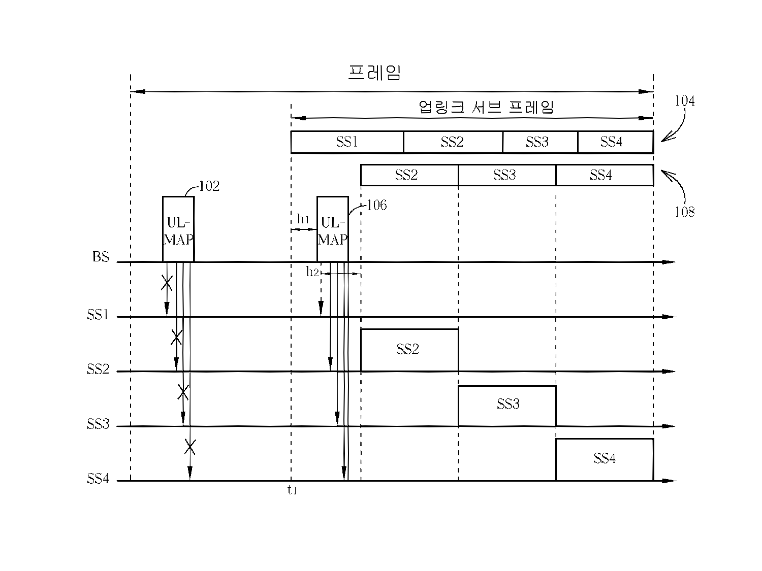
도 1을 참조한다. 도 1은 기지국이 잡음 간섭을 겪을 때 채택되는 본 발명의 대역폭 복구 방법을 예시하는 타이밍도이다. 도 1에 도시된 바와 같이, 다운링크 서브 프레임의 개시 부분에서, 우선 기지국 BS는 업링크 스케줄링 메시지(102)를 자신에게 속하는 가입자국(즉 통신 노드 SS1 내지 SS4)으로 송신한다. 간략화를 위하여, 후술되는 상세한 설명에서 업링크 스케줄링 메시지(102)는 예시적 목적 을 위하여 UL-MAP을 이용하여 구현되고, 가입자국의 개수는 네 개이다. 하지만, 해당 기지국 BS에 상응하는 가입자국의 개수는 본 발명을 한정하는 것이 아니며, 업링크 스케줄링 메시지는 IEEE 802.16 표준을 따르는 UL-MAP에 한정되는 것이 아니라는 점에 주의하여야 한다. 바꾸어 말하면, 본 발명에서 게시된 업링크 스케줄링 방법은 IEEE 802.16 표준을 따르는 통신 시스템에 적용되도록 한정되는 것이 아니다. 예를 들면, 통신 시스템은 케이블 시스템 인터페이스 규격 상의 데이터(Data Over Cable System Interface Specification, DOCSIS) 규격에 따르는 시스템일 수도 있다. Please refer to Fig. 1 is a timing diagram illustrating the bandwidth recovery method of the present invention that is employed when a base station experiences noise interference. As shown in Fig. 1, at the beginning of the downlink subframe, the base station BS first transmits an
업링크 스케줄링 메시지(102)는 각 가입자국(SS1 내지 SS4) 각각이 데이터를 기지국 BS으로 업로딩하기 위한 업링크 시간을 할당하기 위한 스케줄을 포함한다. UL-MAP 내의 콘텐츠는 주로 각각의 가입자국 SSi의 식별자, 각 가입자국의 개시 시간 ti, 및 각 가입자국의 송신 지속 시간 xi(아래첨자 i는 1 내지 4인데 그 이유는 도시된 실시예에 예시적 가입자국이 네 개 존재하기 때문이다)를 포함한다. 개시 시간 ti는 가입자국 SSi가 데이터의 송신을 개시하도록 허용되는 시점을 나타낸다. ti 및 xi 간의 관계는 다음 수학식 1과 같다. The
업링크 스케줄링 콘텐츠(104)는 기지국 BS에 속하는 가입자국 SS1 내지 SS4 의 업링크 버스트 기간의 분배 조건(distribution condition)이다. 가입자국 SS1 내지 SS4 모두가 정확한 업링크 스케줄링 메시지(UL-MAP, 102)를 수신하는 정상적인 경우에, 각 가입자국들은 업링크 스케줄링 콘텐츠(104) 내에 구성된 스케줄을 추종하여 할당된 업링크 시간 기간(uplink time period)에 따라 데이터를 기지국 BS로 업로딩한다. The
기지국 BS에 접근하는 잡음 간섭원이 있을 경우, 업링크 스케줄링 메시지(UL-MAP, 102)는 가입자국 SS1 내지 SS4에 정확하게 수신될 수 없다. 가입자국들 중 어느 것도 업링크 서브 프레임의 기간에서 데이터를 업로딩하지 않을 것이다. 전술한 바와 같은 대역폭 낭비 문제점을 해결하기 위하여, 도시된 실시예의 기지국 BS는 업링크 서브 프레임 지속 시간(duration) 동안에 업링크 채널이 아이들 상태에 있는지 여부를 검출할 것이며, 여기서 업링크 채널은 네 개의 가입자국 SS1 내지 SS4에 의하여 공유된다. If there is a noise interference source approaching the base station BS, the uplink scheduling message (UL-MAP) 102 cannot be correctly received at the subscriber stations SS1 to SS4. None of the subscriber stations will upload data in the period of the uplink subframe. To solve the bandwidth wasting problem described above, the base station BS of the illustrated embodiment will detect whether the uplink channel is in an idle state during the uplink subframe duration, where the uplink channel is four It is shared by subscriber stations SS1 through SS4.
데이터를 업로딩도록 스케줄링된 가입자국 SSi가 개시 시간(즉, 도시된 실시예에서는 t1) 이후에 소정 시간 h1을 초과하는 기간 동안 업로드 동작을 실행하지 않으면, 기지국 BS는 시간 t1 + h1이 지난 뒤에 자신에게 속한 가입자국 SS1 내지 SS4를 향하여 업링크 스케줄링 메시지(106)를 송신할 것이며, 여기서 소정 시간 h1은 전파 시간(propagation time)보다 짧지 않은데, 그 이유는 가입자국은 무선 반송파(wireless carrier)가 전파 시간 동안 공중파를 통하여 이동할 경우에만 무선 반송파를 수신하기 때문이다. If the subscriber station SS i scheduled to upload data does not perform an upload operation for a period of time exceeding the predetermined time h 1 after the start time (ie, t 1 in the illustrated embodiment), the base station BS is time t 1. After + h 1 , the
본 발명은 두 개의 대역폭 복구 방법 R1 및 R2를 제공하여 전술된 바와 같은 대역폭 낭비 문제를 해결한다. 업링크 스케줄링 메시지(UL-MAP, 102)를 송신하기 이전에, 기지국 BS는 가입자국 SSi에 각각 상응하는 각각의 지속 시간 xi가 임계치를 초과하는지 여부를 분석할 것이다. 만일 모든 지속 시간 xi가 임계치를 초과하면, 기지국 BS는 복구 방법 R1 또는 복구 방법 R2 중 하나를 임의로 채택하도록 허용된다. 그렇지 않으면, 기지국 BS는 복구 방법 R1만을 채택하도록 허용된다. 수학식 및 임계치를 산출하는데 대한 관련된 설명이 이하 후술될 것이다. The present invention provides two bandwidth recovery methods R1 and R2 to solve the bandwidth waste problem as described above. Before transmitting the uplink scheduling message (UL-MAP) 102, the base station BS will analyze whether each duration x i corresponding to the subscriber station SS i respectively exceeds the threshold. If all durations x i exceed the threshold, then the base station BS is allowed to arbitrarily adopt either recovery method R1 or recovery method R2. Otherwise, the base station BS is allowed to adopt only recovery method R1. Related descriptions for calculating equations and thresholds will be described below.
복구 방법 R1에 관해서, 기지국 BS는 잔여 업링크 지속 시간(uplink duration)을 재정렬(re-arrange)한다. 도 1에 도시된 바와 같이, 업링크 스케줄링 메시지(UP-MAP, 106) 내의 콘텐츠는 가입자국들로 할당된 신규한 개시 시간 ti * 및 신규한 지속 시간 xi *를 포함한다. 업링크 스케줄링 콘텐츠(108)는 업링크 송신의 새로운 스케줄이다. 가입자국 SS2의 새로운 개시 시간 t2 *는 t1 + h1 + h2와 같으며, 즉 t2 * = (t1 + h1 + h2)이다. 기간 h2는 업링크 스케줄링 메시지(UL-MAP, 106)가 브로드캐스팅된 시점 및 가입자국 SS2의 신규한 개시 시간 t2 *간의 시간차를 나타내고, 지속 시간 h2는 다음 수학식 2의 부등식을 만족한다. Regarding the recovery method R1, the base station BS re-arranges the remaining uplink duration. As shown in FIG. 1, the content in the uplink scheduling message (UP-MAP) 106 includes a new start time t i * and a new duration x i * assigned to subscriber stations.
수학식 2에서, Tproc는 매체 접근 제어(Media Access Control, MAC)에 의해 필요한 처리 시간을 나타내고, TUM은 업링크 스케줄링 메시지(UP-MAP, 106)를 송신하는데 요구되는 시간을 나타내며, STTG는 가입자국 SS2가 수신 모드로부터 송신 모드로 전환하기 위하여 필요한 동작 시간(operating time)을 나타내고, u는 신호 전파 시간을 나타낸다. In Equation 2, T proc represents a processing time required by Media Access Control (MAC), T UM represents a time required for transmitting an uplink scheduling message (UP-MAP) 106, and STTG Denotes an operating time required for the subscriber station SS2 to switch from a reception mode to a transmission mode, and u denotes a signal propagation time.
업링크 스케줄링 메시지(UP-MAP, 106)에 의하여 스케줄링된 신규한 개시 시간은, 업링크 스케줄링 메시지(UP-MAP, 106)의 송신 시간에 특정 지속 시간(즉, h2)을 더한 값과 같으며, 여기서 신규 개시 시간은 가입자국 SS2가 데이터 송신을 개시하도록 허용된 시간을 나타내고, 특정 지속 시간(즉, h2)은 업링크 스케줄링 메시지(UP-MAP, 106)의 송신 시간으로부터 시작하여 가입자국 SS2가 데이터 송신을 개시할 때까지의 동작 시간, 즉, Tproc + TUM + STTG + u 보다 짧지 않다. The new start time scheduled by the uplink scheduling message (UP-MAP) 106 is equal to the transmission time of the uplink scheduling message (UP-MAP) 106 plus the specific duration (i.e., h 2 ). Where the new start time represents the time during which subscriber station SS2 is allowed to initiate data transmission, and the particular duration (i.e., h 2 ) is subscribing starting from the transmission time of the uplink scheduling message (UP-MAP) 106. It is not shorter than the operating time until the local station SS2 starts data transmission, that is, T proc + T UM + STTG + u.
도 2를 참조한다. 도 2는 가입자국(들)이 잡음 간섭을 겪을 때 채택되는 본 발명의 제1 예시적 실시예의 대역폭 복구 방법을 예시하는 타이밍도이다. 도 1에 도시된 동작과 유사하게, 기지국 BS가 업링크 서브 프레임 내의 소정 시간 h1을 초과하는 기간 동안에 업링크 채널이 아이들 상태에 있다는 것을 검출하면, 기지국 BS는 업링크 시간을 재정렬하고, 시간 t1 + h1에서 업링크 스케줄링 메시지(UP-MAP, 206)를 가입자국들(도시된 실시예에서는 SS1 내지 SS4)로 송신한다. 후속되는 절 차들과 관련된 동작들이 상세히 전술된 바 있기 때문에, 이러한 절차들에 대한 후속적인 설명은 명세서의 간략화를 위하여 생략된다. See FIG. 2. 2 is a timing diagram illustrating a bandwidth recovery method of the first exemplary embodiment of the present invention that is employed when the subscriber station (s) experience noise interference. Similar to the operation shown in FIG. 1, if the base station BS detects that the uplink channel is in an idle state for a period of time exceeding a predetermined time h 1 in the uplink subframe, the base station BS rearranges the uplink time, t 1 At + h 1 , an uplink scheduling message (UP-MAP) 206 is sent to subscriber stations (SS1 to SS4 in the illustrated embodiment). Since operations associated with subsequent procedures have been described above in detail, subsequent descriptions of these procedures are omitted for simplicity of specification.
도 3을 참조한다. 도 3은 기지국의 가입자국들이 잡음 간섭을 겪으며 신규한 업링크 스케줄링 메시지를 정확하기 수신하지 못한 경우에 채택되는 제1 예시적인 실시예에 따르는 대역폭 복구 방법을 예시하는 타이밍도이다. 도 3에 도시된 바와 같이, 거의 모든 동작들은 도 1 및 도 2에 예시된 동작들과 유사하다. 주된 차이점은, 가입자국 SS2가 기지국이 신규한 업링크 스케줄링 메시지(UP-MAP, 306)를 송신할 때 잡음 간섭을 겪는다는 것이다. 그 결과, 가입자국 SS2는 업링크 스케줄링 메시지(UP-MAP, 306)를 정확하게 수신하지 못한다. 그러므로, 가입자국 SS2는 잡음 간섭 때문에 업로드 동작을 실행하지 않는다. 도 1 및 도 2에서 예시된 관련 동작들과 유사하게, 기지국 BS가 업링크 스케줄링 메시지(UP-MAP, 306)를 송신한 이후에 소정 값 h1을 초과하는 기간 동안 업링크 채널이 아이들 상태에 있다는 것을 검출하면, 기지국 BS는 잔여 업링크 기간을 재정렬하고, 시간 t1 + h1 + h2 + h1에 신규한 업링크 스케줄링 메시지(UP-MAP, 310)를 가입자국들로 송신한다. 가입자국 SS3 및 SS4는 업링크 스케줄링 메시지(UP-MAP, 310)에 의하여 배달된 업링크 스케줄에 따라서 데이터를 업로딩할 것이다. See FIG. 3. FIG. 3 is a timing diagram illustrating a bandwidth recovery method according to the first exemplary embodiment employed when subscriber stations of a base station suffer from noise interference and fail to correctly receive a new uplink scheduling message. As shown in FIG. 3, almost all of the operations are similar to the operations illustrated in FIGS. 1 and 2. The main difference is that subscriber station SS2 experiences noise interference when the base station transmits a new uplink scheduling message (UP-MAP) 306. As a result, subscriber station SS2 does not correctly receive the uplink scheduling message (UP-MAP) 306. Therefore, subscriber station SS2 does not perform an upload operation because of noise interference. Similar to the related operations illustrated in FIGS. 1 and 2, after the base station BS transmits an uplink scheduling message (UP-MAP) 306, the uplink channel is in an idle state for a period exceeding a predetermined value h 1 . If it is detected that the base station BS rearranges the remaining uplink period, time t 1 + h 1 + h 2 Send a new uplink scheduling message (UP-MAP) 310 to subscriber stations at + h 1 . The subscriber stations SS3 and SS4 will upload the data according to the uplink schedule delivered by the uplink scheduling message (UP-MAP 310).
전술된 실시예들로부터, 복구 방법 R1의 특징은, 기지국 BS가 업링크 스케줄링 메시지(UL-MAP)를 재송신할 때 가입자국들의 업링크 시간을 재정렬 및 재스케줄링한다는 것이다. 또한, 가입자국은 데이터를 송신할 기회를 가지지 못하기 때문 에 업링크 서브 프레임 동안에 청취 상태(listening state)로 유지되어야 하고, 데이터를 업로딩하도록 허용되기 전 전술된 STTBG 시간까지는 청취 상태로부터 송신 상태로 전이하지 않는다. 가입자국이 데이터를 업로딩하기 위하여 대기하는 동안에 업링크 스케줄링 메시지(UP-MAP)를 수신하지 않는 경우에는, 가입자국은 이러한 상황이 충돌 상태(collision state)인 것으로 결정하고, 따라서 업링크 스케줄링 메시지(UP-MAP)가 정확하게 수신될 때까지 일시적으로 업링크 스케줄링을 중단하여야 한다. 그러면, 가입자국은 신규한 업링크 스케줄링 메시지(UP-MAP) 내에 정의된 업링크 스케줄링에 따라서 기지국으로 데이터를 업로딩한다. From the above-described embodiments, the feature of the recovery method R1 is that the base station BS reorders and reschedules the uplink time of the subscriber stations when it retransmits the uplink scheduling message (UL-MAP). In addition, since the subscriber station does not have the opportunity to transmit data, it must remain in the listening state during the uplink subframe, and from the listening state to the transmitting state until the aforementioned STTBG time before being allowed to upload data. Does not metastasize If the subscriber station does not receive an uplink scheduling message (UP-MAP) while waiting to upload data, the subscriber station determines that this situation is a collision state, and thus the uplink scheduling message ( The uplink scheduling should be temporarily suspended until UP-MAP) is correctly received. The subscriber station then uploads the data to the base station according to the uplink scheduling defined in the new uplink scheduling message (UP-MAP).
본 발명의 두 번째 대역폭 복구 방법 R2는, 다음 수학식 3의 조건이 만족될 때까지는 채택되도록 허용되지 않는다. The second bandwidth recovery method R2 of the present invention is not allowed to be adopted until the condition of the following equation (3) is satisfied.
수학식 3의 조건이 1 ≤ i ≤ 4인 i에 대하여 성립하면 제2 대역폭 복구 방법 R2가 채택될 수 있는데, 여기서 D는 전제부 시간(preamble time) 더하기 STTG이고, TBR은 대역폭 요청을 송신하기 위하여 필요한 시간을 나타낸다. The second bandwidth recovery method R2 can be adopted if the condition of Equation 3 is satisfied for i with 1 ≦ i ≦ 4, where D is a preamble time plus STTG and T BR transmits the bandwidth request. It shows the time required to do so.
다운링크 서브 프레임의 개시부에서, 기지국 BS는 우선 모든 자신에게 속한 가입자국들이 다음 수학식 4의 조건을 만족하는지 여부를 검출한다(만일 가입자국의 전체 개수가 N 이라면, 첨자 i는 1 내지 N의 값을 가진다). At the beginning of the downlink subframe, the base station BS first detects whether the subscriber stations belonging to all of them satisfy the condition of the following equation (4) (if the total number of subscriber stations is N, the subscript i is 1 to N). Has the value of).
다시 말하면, 기지국 BS는 데이터를 송신하기 위한 잔여 시간(이 시간은 할당된 업링크 기간 xi로부터 업링크 스케줄링 메시지(UP-MAP)를 송신 및 처리하기 위하여 요청되는 시간을 공제한 결과와 동일하다)이 최소 데이터 단위를 송신하기 위하여 필요한 시간(즉, D + TBR)보다 긴 지 점검하는데, 여기서 최소 데이터 단위(minimum data unit)란 전제부 비트(preamble bits) 및 대역폭 요청(bandwidth request)의 합을 나타낸다. 그 이유는, 대역폭 복구 방법 R2가, 다운링크 서브 동안에 업링크 스케줄링 메시지를 수신하지 못하는 특정한 가입자국(들)을 제외하고는, 지속 시간 xi를 재정렬하지 않기 때문이다. 수학식 3의 조건 xi ≥ h1 + h2 + D + TBR은 대역폭 복구 방법 R2를 채택하기 위한 전제 조건(premise condition)이다.In other words, the base station BS is equal to the result of subtracting the remaining time for transmitting data (the time required for transmitting and processing the uplink scheduling message UP-MAP from the assigned uplink period x i ). ) Is longer than the time required to transmit the minimum data unit (i.e., D + T BR ), where the minimum data unit is the length of the preamble bits and bandwidth request. Represents the sum. The reason is that the bandwidth recovery method R2 does not rearrange the duration x i except for the particular subscriber station (s) that do not receive the uplink scheduling message during the downlink sub. The condition x i ≥ h 1 + h 2 + D + T BR of Equation 3 is a precondition for adopting the bandwidth recovery method R2.
도 4를 참조한다. 도 4는 가입자국(들)이 잡음 간섭을 겪을 때 채택되는 제2 예시적 실시예에 따르는 대역폭 복구 방법을 예시하는 타이밍도이다. 도 4에 도시된 바와 같이, 다운링크 서브 프레임의 개시부에서, 기지국 BS는 제2 대역폭 복구 방법 R2 (xi ≥ h1 + h2 + D + TBR, 1 ≤ i ≤ 4인 모든 i에 대하여)를 채택하며, 업링크 스케줄링 메시지(UP-MAP, 402)를 자신에게 속한 가입자국들 SS1 내지 SS4로 송신한다. 가입자국 SS1 내지 SS4들은 업링크 스케줄링 콘텐츠(404)에 따라 업로드 동작을 실행할 것이다. 도 4에 도시된 바와 같이, 가입자국 SS1이 업링크 스케줄링 메시지(UP-MAP, 402)를 정확하게 수신하지 못하기 때문에, 가입자국 SS1은 개 시 시간 t1이후에 데이터를 기지국 BS로 업로딩하지 않는다. 기지국 BS가 해당 업링크 채널이 가입자국 SS1의 개시 시간 t1 이후 미리 결정된 시간 h1을 초과하고 있는 기간 동안 아이들 상태에 있다고 검출하면, 기지국 BS는 이번에는 우선 잔여 업링크 기간이 h2 + D + TBR보다 더 긴지 여부를 점검하고, 잔여 업링크 기간이 h2 + D + TBR보다 더 길 경우 자신에게 속하는 가입자국들 SS1 내지 SS4로 신규한 업링크 스케줄링 메시지(UP-MAP, 406)를 송신한다. 도 4에 도시된 본 발명의 실시예에서는, 업링크 스케줄링 메시지(UP-MAP, 406)를 통하여 운반되는 업링크 스케줄링 콘텐츠(408) 및 업링크 스케줄링 메시지(UP-MAP, 402)를 통하여 운반되는 업링크 스케줄링 콘텐츠(404)는 대략적으로 같으나(예를 들어, 가입자국 SS2 내지 SS4에 대한 개시 시간 t2 - t4 및 지속 시간 x2 - x4들은 동일한 상태로 유지된다), 가입자국 SS1의 스케줄링만이 변경된다. 가입자국 SS1에 관해서는, 할당된 업링크 지속 시간이 단지 x1 - (h1 + h2)일 뿐이며, 이것은 업링크 스케줄링 메시지(UP-MAP, 402)에 의하여 설정된 애초에 할당된 업링크 지속 시간 x1보다 짧다. See FIG. 4. 4 is a timing diagram illustrating a bandwidth recovery method according to the second exemplary embodiment that is employed when the subscriber station (s) experience noise interference. As shown in FIG. 4, at the beginning of the downlink subframe, the base station BS is assigned to every i with the second bandwidth recovery method R2 (x i ≧ h 1 + h 2 + D + T BR , 1 ≦ i ≦ 4). And uplink scheduling message (UP-MAP) 402 to subscriber stations SS1 to SS4 belonging to it. Subscriber stations SS1 through SS4 will perform the upload operation in accordance with the
본 발명에서, 업링크 스케줄링 메시지(UP-MAP, 406)도 역시 예를 들어 가입자국 SS4와 같은 다른 가입자국들로 추가적 지속 시간을 설정할 수 있다는 점에 주의하여야 하는데, 이러한 동작은 가입자국 SS1에 원래 할당된 잔여 업링크 지속 시간을 이용함으로써 수행된다. 그 결과로서, 가입자국 SS4는 데이터를 기지국 BS로 업로딩하기 위하여 할당된 두 개의 업링크 지속 시간을 가진다. 또한, 이와 같은 대안적 설계 역시 본 발명의 기술적 사상 내에 포함된다. In the present invention, it should be noted that the uplink scheduling message (UP-MAP) 406 may also set additional durations with other subscriber stations, for example subscriber station SS4, which operation is performed at subscriber station SS1. This is done by using the originally allocated residual uplink duration. As a result, subscriber station SS4 has two uplink durations allocated for uploading data to the base station BS. In addition, such alternative designs are also included within the technical spirit of the present invention.
복구 방법 R1 및 R2 사이의 중대한 차이점은, 대역폭 복구 방법 R2가 구현되는 경우에 기지국 BS가 가입자국들의 업링크 지속 시간을 재정렬 및 재스케줄링하지 않는다는 점이다. 또한, 가입자국 SS1 내지 SS4들은 데이터의 업로딩을 개시하기 이전에 오직 한번만 업링크 스케줄링 메시지(UP-MAP)를 수신하도록 요구된다. 도 4에 제시된 바와 같이, 비록 가입자국 SS2가 업링크 스케줄링 메시지(UP-MAP, 406)를 수신하지 않는다 하여도, 가입자국 SS2는 할당된 개시 시간 t2에서 기지국 BS로 데이터를 송신할 수 있는데, 그 이유는 사전에 브로드캐스팅된 업링크 스케줄링 메시지(UP-MAP, 402)가 다운링크 서브 프레임의 개시 시점에 가입자국 SS2에 의하여 성공적으로 수신된 바 있기 때문이다. The significant difference between the recovery methods R1 and R2 is that the base station BS does not reorder and reschedule uplink durations of subscriber stations when the bandwidth recovery method R2 is implemented. In addition, subscriber stations SS1 through SS4 are required to receive an uplink scheduling message (UP-MAP) only once before initiating uploading of data. As shown in Figure 4, even though subscriber station SS2 does not receive the uplink scheduling message (UP-MAP) 406, subscriber station SS2 can transmit data to the base station BS at the assigned start time t 2 . This is because the pre-broadcast uplink scheduling message (UP-MAP) 402 has been successfully received by subscriber station SS2 at the start of the downlink subframe.
도 5를 참조한다. 도 5는 업링크 채널이 패딩 낭비 상태에 놓여 있을 때 채택되는 제1 예시적 실시예에 따르는 대역폭 복구 방법을 예시하는 타이밍도이다. 도 5에 도시된 바와 같이, 도시된 실시예에서, 만일 가입자국 SS2의 업링크 기간 x2가 실제로 요구되는 것보다 더 길다면, 가입자국 SS2가 송신 동작을 완료한 이후에, 가입자국 SS2는 패딩 데이터를 전달하지 않는다. 그 결과로써, 가입자국 SS2로 할당된 추가적 지속 시간 동안에 업링크 채널은 아이들 상태가 될 것이다. 도 5에 도시된 바와 같이, 기지국 BS는 우선 전술된 바와 같이 검출 동작을 수행하고, 그 이후에 업링크 스케줄링 메시지(UP-MAP, 506)를 송신한다. 현재의 실시예에서, 기지국 BS는 대역폭 복구 방법 R2를 채택하여, 애초에 가입자국 SS2에게 할당된 바 있는 지속 시간의 잔여분을 두 개의 가입자국 SS3 및 SS4로 각각 분배한다. 도 5에 도시된 바와 같이 지속 시간의 잔여분이 T3 + T4라고 가정한다. 신규한 업링크 스케줄링 메시지(UP-MAP, 506) 내에서, 가입자국 SS3의 신규한 지속 시간 x3 *는 x3 + T3에 의하여 설정되고(즉, x3 * = x3 + T3), 가입자국 SS4의 신규한 지속 시간 x4 *는 x4 + T4에 의하여 설정된다(즉, x4 * = x4 + T4). 도 5에 도시된 현재의 실시예에서, 잔여 가용 지속 시간은 가입자국 S3 및 S4로 균일하게 분배된다는 점에 주의하여야 한다. 그러나, 이것은 예시적인 목적으로 제공된 것일 뿐이며 본 발명의 기술적 범위를 한정하려는 것이 아니다. 본 발명의 다른 실시예들에서, 데이터 송신을 위하여 가입자국 SS2에 의해 이용되지 않는 나머지 업링크 기간은 설계 요건에 따라 후속 가입자국들로 적당하게 분배될 수 있고, 후속 가입자국들에게 균일하게 분배되는 데에 한정되지 않는다. 이러한 대안적 설계들도 본 발명의 기술적 사상에 따르는 것이며 본 발명의 기술적 범위 내에 포함된다. See FIG. 5. FIG. 5 is a timing diagram illustrating a bandwidth recovery method according to the first exemplary embodiment that is employed when the uplink channel is in a padded waste state. As shown in Fig. 5, in the illustrated embodiment, if the uplink period x 2 of subscriber station SS2 is longer than actually required, after subscriber station SS2 completes the transmission operation, subscriber station SS2 is padded. Do not pass data. As a result, the uplink channel will be idle for the additional duration assigned to subscriber station SS2. As shown in FIG. 5, the base station BS first performs a detection operation as described above, and then transmits an uplink scheduling message (UP-MAP) 506. In the present embodiment, the base station BS adopts the bandwidth recovery method R2 to distribute the remainder of the duration originally assigned to the subscriber station SS2 to the two subscriber stations SS3 and SS4, respectively. As shown in FIG. 5, the remainder of the duration is T 3. Assume + T 4 . Within the new uplink scheduling message (UP-MAP) 506, the new duration x 3 * of the subscriber station SS3 is set by x 3 + T 3 (ie, x 3 * = x 3 + T 3 ). , The new duration x 4 * of the subscriber station SS4 is set by x 4 + T 4 (ie x 4 * = x 4 + T 4 ). It should be noted that in the present embodiment shown in FIG. 5, the remaining available duration is evenly distributed to subscriber stations S3 and S4. However, this is provided for illustrative purposes only and is not intended to limit the technical scope of the present invention. In other embodiments of the present invention, the remaining uplink periods not used by subscriber station SS2 for data transmission may be appropriately distributed to subsequent subscriber stations according to design requirements, and evenly distributed to subsequent subscriber stations. It is not limited to being. Such alternative designs are also in accordance with the spirit of the present invention and are included within the technical scope of the present invention.
도 6을 참조한다. 도 6은 업링크 채널이 패딩 낭비 상태에 놓여 있을 때 채택되는 제2 예시적 실시예에 따르는 대역폭 복구 방법을 예시하는 타이밍도이다. 가입자국 SS2의 업링크 기간 x2가 가입자국 SS2에 의하여 실제로 요구되는 것보다 더 길고, 가입자국 SS2가 업로딩 동작을 종결한 이후에는 패딩 데이터를 전달하지 않는다고 가정한다. 그 결과로써, 지속 시간 x2의 잔여부에서, 업링크 채널은 아이 들 상태가 된다. 도 6에 도시된 바와 같이, 기지국 BS는 우선 전술된 바와 같이 검출 동작을 수행하고, 그 이후에 지속 시간 x2의 잔여부가 H2 + D + TBR보다 긴지 여부를 점검한다. 잔여 지속 시간이 H2 + D + TBR보다 길다면, 업링크 스케줄링 메시지(UP-MAP, 606)가 송신된다. 기지국 BS는 대역폭 복구 방법 R2를 채택할 것이며, 즉, 업링크 스케줄링 메시지(UP-MAP, 602) 내의 업링크 스케줄링 콘텐츠(604)에 따라서 가입자국 SS2에 의하여 이용되지 않는 잔여 지속 시간을 직접 후속하는 가입자국 SS3에만 할당할 것이다. 잔여 지속 시간이 도 6에 도시된 바와 같이 t3라고 표시된다고 가정한다. 신규한 업링크 스케줄링 메시지(UP-MAP, 606)에서, 가입자국 SS3의 신규한 지속 시간 x3 *는 x3 + T3에 의하여 설정되고(즉, x3 * = x3 + T3), 가입자국 SS4의 신규한 지속 시간 x4 *는 여전히 x4와 같다(즉, x4 * = x4)이다.See FIG. 6. 6 is a timing diagram illustrating a bandwidth recovery method according to a second exemplary embodiment that is employed when an uplink channel is placed in a padding wasted state. Assume that the uplink period x 2 of subscriber station SS2 is longer than actually required by subscriber station SS2, and does not pass padding data after subscriber station SS2 has finished the uploading operation. As a result, at the remainder of the duration x 2 , the uplink channel is in the idle state. As shown in FIG. 6, the base station BS first performs a detection operation as described above, after which the remainder of the duration x 2 is added to H 2. Check whether it is longer than + D + T BR . Remaining duration is H 2 If longer than + D + T BR , an uplink scheduling message (UP-MAP) 606 is transmitted. The base station BS will adopt the bandwidth recovery method R2, i.e. directly following the remaining duration not used by the subscriber station SS2 according to the uplink scheduling content 604 in the uplink scheduling message (UP-MAP) 602. It will only be assigned to subscriber station SS3. Assume that the remaining duration is indicated by t 3 as shown in FIG. 6. In the new uplink scheduling message (UP-MAP) 606, the new duration x 3 * of the subscriber station SS3 is set by x 3 + T 3 (ie, x 3 * = x 3 + T 3 ), The new duration x 4 * of subscriber station SS4 is still equal to x 4 (ie x 4 * = x 4 ).
도 1 내지 도 6에 예시된 바와 같은 전술된 실시예들로부터 개시된 대역폭 복구 방법은 예시적인 목적으로 제공된 것일 뿐이며, 본 발명의 기술적 사상을 한정하려고 하는 것은 아님을 명심한다. 더 나아가, 비록 전술된 실시예들이 IEEE 802.16 표준을 따르는 통신 시스템에 적용되는 것으로 도시되었으나, 본 발명에 의하여 제공되는 대역폭 복구 방법은 시분할 다중화(TDM) 시스템을 이용하는 모든 통신 시스템에도 적용될 수 있다는 점을 유념한다. 이들 모두는 본 발명의 기술적 범위 내에 포함된다. It should be noted that the bandwidth recovery method disclosed from the above-described embodiments as illustrated in FIGS. 1 to 6 is provided for illustrative purposes only and is not intended to limit the technical spirit of the present invention. Furthermore, although the above-described embodiments are shown to be applied to a communication system conforming to the IEEE 802.16 standard, the bandwidth recovery method provided by the present invention can be applied to any communication system using a time division multiplexing (TDM) system. Keep in mind. All of these are included within the technical scope of the present invention.
본 발명의 장점은 업링크 스케줄링 메시지(IEEE 802.16 표준 내에 정의된 UL-MAP과 같은 메시지)의 재송신 기법을 통하여, 원래 아이들 상태 상태였던 업링크 채널이 더 효율적으로 이용될 수 있기 때문에 종래 기술에 의한 대역폭 낭비 문제점을 해결할 수 있다는 점이다. An advantage of the present invention is that, through the retransmission scheme of uplink scheduling messages (messages such as UL-MAP defined in the IEEE 802.16 standard), the uplink channel, which was originally in an idle state, can be used more efficiently. It can solve the bandwidth waste problem.
당업자들은 본 발명의 교시 내용에 벗어나지 않는 범위에서 설명된 장치 및 방법에 다양한 수정을 가하거나 일부를 변경하는 것이 가능하다는 점을 용이하게 이해할 수 있을 것이다. Those skilled in the art will readily appreciate that various modifications or changes may be made to the apparatus and methods described without departing from the teachings of the present invention.
본 발명은 통신 시스템에 적용될 수 있으며, 특히 통신 시스템의 대역폭 복구를 처리하기 위하여 적용될 수 있다. The present invention can be applied to a communication system, and in particular, to handle bandwidth recovery of a communication system.
도 1은 기지국이 잡음 간섭을 겪을 때 채택되는 본 발명의 대역폭 복구 방법을 예시하는 타이밍도이다. 1 is a timing diagram illustrating the bandwidth recovery method of the present invention that is employed when a base station experiences noise interference.
도 2는 가입자국이 잡음 간섭을 겪을 때 채택되는 본 발명의 제1 예시적 실시예의 대역폭 복구 방법을 예시하는 타이밍도이다. 2 is a timing diagram illustrating the bandwidth recovery method of the first exemplary embodiment of the present invention employed when a subscriber station is subjected to noise interference.
도 3은 기지국의 가입자국들이 잡음 간섭을 겪으며 신규한 업링크 스케줄링 메시지를 정확하기 수신하지 못한 경우에 채택되는 제1 예시적인 실시예에 따르는 대역폭 복구 방법을 예시하는 타이밍도이다. FIG. 3 is a timing diagram illustrating a bandwidth recovery method according to the first exemplary embodiment employed when subscriber stations of a base station suffer from noise interference and fail to correctly receive a new uplink scheduling message.
도 4는 가입자국(들)이 잡음 간섭을 겪을 때 채택되는 제2 예시적 실시예에 따르는 대역폭 복구 방법을 예시하는 타이밍도이다. 4 is a timing diagram illustrating a bandwidth recovery method according to the second exemplary embodiment that is employed when the subscriber station (s) experience noise interference.
도 5는 업링크 채널이 패딩 낭비 상태에 놓여 있을 때 채택되는 제1 예시적 실시예에 따르는 대역폭 복구 방법을 예시하는 타이밍도이다. FIG. 5 is a timing diagram illustrating a bandwidth recovery method according to the first exemplary embodiment that is employed when the uplink channel is in a padded waste state.
도 6은 업링크 채널이 패딩 낭비 상태에 놓여 있을 때 채택되는 제2 예시적 실시예에 따르는 대역폭 복구 방법을 예시하는 타이밍도이다. 6 is a timing diagram illustrating a bandwidth recovery method according to a second exemplary embodiment that is employed when an uplink channel is placed in a padding wasted state.
Claims (16)
Applications Claiming Priority (2)
| Application Number | Priority Date | Filing Date | Title |
|---|---|---|---|
| TW096145936A TWI383636B (en) | 2007-12-03 | 2007-12-03 | Bandwidth recovery method for communication system |
| TW096145936 | 2007-12-03 |
Publications (2)
| Publication Number | Publication Date |
|---|---|
| KR20090057860A KR20090057860A (en) | 2009-06-08 |
| KR100960649B1 true KR100960649B1 (en) | 2010-06-07 |
Family
ID=40675624
Family Applications (1)
| Application Number | Title | Priority Date | Filing Date |
|---|---|---|---|
| KR1020080003073A Active KR100960649B1 (en) | 2007-12-03 | 2008-01-10 | Method for Bandwidth Recovery of Communication System |
Country Status (4)
| Country | Link |
|---|---|
| US (1) | US8457095B2 (en) |
| KR (1) | KR100960649B1 (en) |
| CA (1) | CA2616931C (en) |
| TW (1) | TWI383636B (en) |
Families Citing this family (30)
| Publication number | Priority date | Publication date | Assignee | Title |
|---|---|---|---|---|
| US8713623B2 (en) | 2001-09-20 | 2014-04-29 | Time Warner Cable Enterprises, LLC | Technique for effectively providing program material in a cable television system |
| US9723267B2 (en) | 2004-12-15 | 2017-08-01 | Time Warner Cable Enterprises Llc | Method and apparatus for wideband distribution of content |
| US8520850B2 (en) | 2006-10-20 | 2013-08-27 | Time Warner Cable Enterprises Llc | Downloadable security and protection methods and apparatus |
| US8621540B2 (en) | 2007-01-24 | 2013-12-31 | Time Warner Cable Enterprises Llc | Apparatus and methods for provisioning in a download-enabled system |
| US8281352B2 (en) | 2007-05-15 | 2012-10-02 | Time Warner Cable Inc. | Methods and apparatus for bandwidth recovery in a network |
| US9357247B2 (en) | 2008-11-24 | 2016-05-31 | Time Warner Cable Enterprises Llc | Apparatus and methods for content delivery and message exchange across multiple content delivery networks |
| US9215423B2 (en) | 2009-03-30 | 2015-12-15 | Time Warner Cable Enterprises Llc | Recommendation engine apparatus and methods |
| US11076189B2 (en) | 2009-03-30 | 2021-07-27 | Time Warner Cable Enterprises Llc | Personal media channel apparatus and methods |
| US9602864B2 (en) | 2009-06-08 | 2017-03-21 | Time Warner Cable Enterprises Llc | Media bridge apparatus and methods |
| US8396055B2 (en) | 2009-10-20 | 2013-03-12 | Time Warner Cable Inc. | Methods and apparatus for enabling media functionality in a content-based network |
| US10264029B2 (en) | 2009-10-30 | 2019-04-16 | Time Warner Cable Enterprises Llc | Methods and apparatus for packetized content delivery over a content delivery network |
| US9519728B2 (en) | 2009-12-04 | 2016-12-13 | Time Warner Cable Enterprises Llc | Apparatus and methods for monitoring and optimizing delivery of content in a network |
| US9342661B2 (en) | 2010-03-02 | 2016-05-17 | Time Warner Cable Enterprises Llc | Apparatus and methods for rights-managed content and data delivery |
| US9236975B2 (en) * | 2010-03-08 | 2016-01-12 | Broadcom Corporation | Mobile subscriber information transmission over multiple uplink frames |
| US8867459B2 (en) * | 2010-03-08 | 2014-10-21 | Broadcom Corporation | Mobile subscriber information transmission over multiple uplink frames |
| US9300445B2 (en) | 2010-05-27 | 2016-03-29 | Time Warner Cable Enterprise LLC | Digital domain content processing and distribution apparatus and methods |
| US9906838B2 (en) | 2010-07-12 | 2018-02-27 | Time Warner Cable Enterprises Llc | Apparatus and methods for content delivery and message exchange across multiple content delivery networks |
| US8997136B2 (en) | 2010-07-22 | 2015-03-31 | Time Warner Cable Enterprises Llc | Apparatus and methods for packetized content delivery over a bandwidth-efficient network |
| US9185341B2 (en) | 2010-09-03 | 2015-11-10 | Time Warner Cable Enterprises Llc | Digital domain content processing and distribution apparatus and methods |
| US9602414B2 (en) | 2011-02-09 | 2017-03-21 | Time Warner Cable Enterprises Llc | Apparatus and methods for controlled bandwidth reclamation |
| JP5694079B2 (en) * | 2011-07-26 | 2015-04-01 | 株式会社東芝 | Transmitting apparatus and transmitting method |
| US9137727B2 (en) * | 2012-03-30 | 2015-09-15 | Hewlett-Packard Development Company, L.P. | Controlled client roaming |
| US9467723B2 (en) | 2012-04-04 | 2016-10-11 | Time Warner Cable Enterprises Llc | Apparatus and methods for automated highlight reel creation in a content delivery network |
| US20140082645A1 (en) | 2012-09-14 | 2014-03-20 | Peter Stern | Apparatus and methods for providing enhanced or interactive features |
| US9565472B2 (en) | 2012-12-10 | 2017-02-07 | Time Warner Cable Enterprises Llc | Apparatus and methods for content transfer protection |
| KR102140276B1 (en) * | 2014-03-31 | 2020-07-31 | 엘지이노텍 주식회사 | Light Emitting Module |
| US9621940B2 (en) | 2014-05-29 | 2017-04-11 | Time Warner Cable Enterprises Llc | Apparatus and methods for recording, accessing, and delivering packetized content |
| US10116676B2 (en) | 2015-02-13 | 2018-10-30 | Time Warner Cable Enterprises Llc | Apparatus and methods for data collection, analysis and service modification based on online activity |
| US9801197B2 (en) * | 2015-05-07 | 2017-10-24 | Qualcomm Incorporated | Mitigation of interference between co-located radio access technologies |
| US10404758B2 (en) | 2016-02-26 | 2019-09-03 | Time Warner Cable Enterprises Llc | Apparatus and methods for centralized message exchange in a user premises device |
Citations (1)
| Publication number | Priority date | Publication date | Assignee | Title |
|---|---|---|---|---|
| WO2007089797A2 (en) * | 2006-01-31 | 2007-08-09 | Interdigital Technology Corporation | Method and apparatus for providing and utilizing a non-contention based channel in a wireless communication system |
Family Cites Families (14)
| Publication number | Priority date | Publication date | Assignee | Title |
|---|---|---|---|---|
| US5751708A (en) * | 1995-10-25 | 1998-05-12 | Lucent Technologies Inc. | Access method for broadband and narrowband networks |
| US20050157674A1 (en) * | 2003-10-31 | 2005-07-21 | Globespanvirata Incorporated | Time-scheduled multichannel direct link |
| EP1745567B1 (en) * | 2004-05-13 | 2017-06-14 | QUALCOMM Incorporated | Non-frequency translating repeater with detection and media access control |
| KR101053610B1 (en) * | 2004-06-25 | 2011-08-03 | 엘지전자 주식회사 | Radio resource allocation method of OPDM / OPDM system |
| US7567565B2 (en) * | 2005-02-01 | 2009-07-28 | Time Warner Cable Inc. | Method and apparatus for network bandwidth conservation |
| KR100615139B1 (en) * | 2005-10-18 | 2006-08-22 | 삼성전자주식회사 | Method and apparatus for allocating transmission period in wireless telecommunication system and therefor system |
| US7869390B2 (en) * | 2006-01-03 | 2011-01-11 | Samsung Electronics Co., Ltd. | Method and system for power save multi-poll (PSMP) communication in wireless systems |
| US7831002B2 (en) * | 2006-10-11 | 2010-11-09 | The Boeing Company | System, apparatus and method for synchronizing a spreading sequence transmitted during a plurality of time slots |
| KR20060133070A (en) | 2006-10-30 | 2006-12-22 | 마츠시타 덴끼 산교 가부시키가이샤 | Scheduling algorithm and scheduler with minimum resource parameters |
| KR100961453B1 (en) | 2006-11-01 | 2010-06-08 | 삼성전자주식회사 | Update-based Resource Allocation Apparatus and Method in Broadband Wireless Access Systems |
| US8503403B2 (en) * | 2006-12-21 | 2013-08-06 | Sony Corporation | Network control of uplink transmit timing for compressed mode |
| US7937090B2 (en) * | 2006-12-26 | 2011-05-03 | Wi-Lan Inc. | Shorthand connection identifier with embedded subfield |
| WO2009019611A2 (en) * | 2007-03-21 | 2009-02-12 | Marvell Dspc Ltd. | Usf coding |
| US8139582B2 (en) * | 2007-05-17 | 2012-03-20 | Samsung Electronics Co., Ltd. | Method and apparatus for making transport frame and method and apparatus for processing transport frame |
-
2007
- 2007-12-03 TW TW096145936A patent/TWI383636B/en active
- 2007-12-21 US US11/962,106 patent/US8457095B2/en not_active Expired - Fee Related
- 2007-12-21 CA CA2616931A patent/CA2616931C/en active Active
-
2008
- 2008-01-10 KR KR1020080003073A patent/KR100960649B1/en active Active
Patent Citations (1)
| Publication number | Priority date | Publication date | Assignee | Title |
|---|---|---|---|---|
| WO2007089797A2 (en) * | 2006-01-31 | 2007-08-09 | Interdigital Technology Corporation | Method and apparatus for providing and utilizing a non-contention based channel in a wireless communication system |
Also Published As
| Publication number | Publication date |
|---|---|
| TW200926710A (en) | 2009-06-16 |
| US20090141696A1 (en) | 2009-06-04 |
| US8457095B2 (en) | 2013-06-04 |
| CA2616931C (en) | 2014-10-14 |
| TWI383636B (en) | 2013-01-21 |
| KR20090057860A (en) | 2009-06-08 |
| CA2616931A1 (en) | 2009-06-03 |
Similar Documents
| Publication | Publication Date | Title |
|---|---|---|
| KR100960649B1 (en) | Method for Bandwidth Recovery of Communication System | |
| KR101361022B1 (en) | Method and apparatus for reporting buffer status | |
| CN108566300B (en) | Terminal and method for sending buffer status report in wireless communication system | |
| US8345690B2 (en) | Selective combining method and apparatus in a mobile communication system | |
| CN102763481B (en) | For in wireless communication system based on competition up link transmit method and apparatus | |
| US20190254058A1 (en) | Data transmission method and apparatus | |
| US20100077100A1 (en) | Method and related device of a trigger mechanism of buffer status report and scheduling request in a wireless communication system | |
| EP2475208A1 (en) | Method and evolved nodeb for semi-persistent scheduling reactivation | |
| KR101999852B1 (en) | Method for communicating in a network, a secondary station and a system therefor | |
| CN102026411B (en) | Method, system and device for transmitting MAC PDU | |
| CN101959139A (en) | Method for processing unicast transmission of multimedia broadcast multicast service subframe | |
| CN101998522B (en) | Buffer state information report processing method and relay node | |
| CN101969669A (en) | Method, system and device for adjusting data volume | |
| CN114258159A (en) | Method, device and equipment for configuring small data and storage medium | |
| CN102017754B (en) | Resource Allocation in Two Domains | |
| CN112805953A (en) | Communication device, infrastructure equipment and method | |
| US8279815B2 (en) | Resource allocation apparatus and method for reducing overhead in mobile communication system | |
| CN118590193A (en) | A transmission method, device and system | |
| US8385279B2 (en) | Resource allocation apparatus and method for reducing overhead in mobile communication system | |
| KR20110021604A (en) | Resource allocation device and method for reducing overhead in mobile communication system | |
| CN102067501B (en) | A Mechanism to Maximize Uplink Bandwidth Through Overlapping Control Regions in WIMAX Systems | |
| KR101422012B1 (en) | Method for generating control channel and decoding control channel, Base station and Mobile station thereof | |
| US20110194512A1 (en) | Method and apparatus for resource allocation scheduling in wireless communication system | |
| CN108809493B (en) | Information sending and receiving method, device, equipment and storage medium | |
| CN101459590B (en) | Bandwidth recovery method applied to communication system |
Legal Events
| Date | Code | Title | Description |
|---|---|---|---|
| A201 | Request for examination | ||
| PA0109 | Patent application |
Patent event code: PA01091R01D Comment text: Patent Application Patent event date: 20080110 |
|
| PA0201 | Request for examination | ||
| PG1501 | Laying open of application | ||
| E902 | Notification of reason for refusal | ||
| PE0902 | Notice of grounds for rejection |
Comment text: Notification of reason for refusal Patent event date: 20091020 Patent event code: PE09021S01D |
|
| E701 | Decision to grant or registration of patent right | ||
| PE0701 | Decision of registration |
Patent event code: PE07011S01D Comment text: Decision to Grant Registration Patent event date: 20100305 |
|
| GRNT | Written decision to grant | ||
| PR0701 | Registration of establishment |
Comment text: Registration of Establishment Patent event date: 20100524 Patent event code: PR07011E01D |
|
| PR1002 | Payment of registration fee |
Payment date: 20100525 End annual number: 3 Start annual number: 1 |
|
| PG1601 | Publication of registration | ||
| FPAY | Annual fee payment |
Payment date: 20130508 Year of fee payment: 4 |
|
| PR1001 | Payment of annual fee |
Payment date: 20130508 Start annual number: 4 End annual number: 4 |
|
| FPAY | Annual fee payment |
Payment date: 20140513 Year of fee payment: 5 |
|
| PR1001 | Payment of annual fee |
Payment date: 20140513 Start annual number: 5 End annual number: 5 |
|
| FPAY | Annual fee payment |
Payment date: 20150511 Year of fee payment: 6 |
|
| PR1001 | Payment of annual fee |
Payment date: 20150511 Start annual number: 6 End annual number: 6 |
|
| FPAY | Annual fee payment |
Payment date: 20160511 Year of fee payment: 7 |
|
| PR1001 | Payment of annual fee |
Payment date: 20160511 Start annual number: 7 End annual number: 7 |
|
| FPAY | Annual fee payment |
Payment date: 20170515 Year of fee payment: 8 |
|
| PR1001 | Payment of annual fee |
Payment date: 20170515 Start annual number: 8 End annual number: 8 |
|
| FPAY | Annual fee payment |
Payment date: 20190517 Year of fee payment: 10 |
|
| PR1001 | Payment of annual fee |
Payment date: 20190517 Start annual number: 10 End annual number: 10 |
|
| PR1001 | Payment of annual fee |
Payment date: 20200514 Start annual number: 11 End annual number: 11 |
|
| PR1001 | Payment of annual fee |
Payment date: 20230509 Start annual number: 14 End annual number: 14 |