KR100957620B1 - Material for organic photoelectric device, and organic photoelectric device using same - Google Patents
Material for organic photoelectric device, and organic photoelectric device using same Download PDFInfo
- Publication number
- KR100957620B1 KR100957620B1 KR1020070110984A KR20070110984A KR100957620B1 KR 100957620 B1 KR100957620 B1 KR 100957620B1 KR 1020070110984 A KR1020070110984 A KR 1020070110984A KR 20070110984 A KR20070110984 A KR 20070110984A KR 100957620 B1 KR100957620 B1 KR 100957620B1
- Authority
- KR
- South Korea
- Prior art keywords
- group
- formula
- carbon atoms
- substituted
- unsubstituted
- Prior art date
- Legal status (The legal status is an assumption and is not a legal conclusion. Google has not performed a legal analysis and makes no representation as to the accuracy of the status listed.)
- Active
Links
- 239000000463 material Substances 0.000 title claims abstract description 62
- 150000002894 organic compounds Chemical class 0.000 claims abstract description 28
- 239000000126 substance Substances 0.000 claims abstract description 20
- 125000004432 carbon atom Chemical group C* 0.000 claims description 108
- 150000001875 compounds Chemical class 0.000 claims description 43
- 125000001424 substituent group Chemical group 0.000 claims description 43
- 125000001072 heteroaryl group Chemical group 0.000 claims description 40
- 125000003118 aryl group Chemical group 0.000 claims description 36
- 125000004435 hydrogen atom Chemical group [H]* 0.000 claims description 27
- 125000000217 alkyl group Chemical group 0.000 claims description 26
- 239000002019 doping agent Substances 0.000 claims description 22
- 230000005525 hole transport Effects 0.000 claims description 20
- 239000010409 thin film Substances 0.000 claims description 20
- 229910052799 carbon Inorganic materials 0.000 claims description 19
- 125000000732 arylene group Chemical group 0.000 claims description 18
- 238000002347 injection Methods 0.000 claims description 18
- 239000007924 injection Substances 0.000 claims description 18
- 125000002947 alkylene group Chemical group 0.000 claims description 17
- 125000005549 heteroarylene group Chemical group 0.000 claims description 16
- 238000000034 method Methods 0.000 claims description 15
- 150000001721 carbon Chemical class 0.000 claims description 13
- -1 biphenylyl group Chemical group 0.000 claims description 8
- 125000001188 haloalkyl group Chemical group 0.000 claims description 7
- 125000005843 halogen group Chemical group 0.000 claims description 7
- 229910052717 sulfur Inorganic materials 0.000 claims description 7
- 125000004430 oxygen atom Chemical group O* 0.000 claims description 6
- 125000004434 sulfur atom Chemical group 0.000 claims description 6
- 229910052757 nitrogen Inorganic materials 0.000 claims description 5
- 229910052760 oxygen Inorganic materials 0.000 claims description 4
- 125000000641 acridinyl group Chemical group C1(=CC=CC2=NC3=CC=CC=C3C=C12)* 0.000 claims description 2
- 125000005428 anthryl group Chemical group [H]C1=C([H])C([H])=C2C([H])=C3C(*)=C([H])C([H])=C([H])C3=C([H])C2=C1[H] 0.000 claims description 2
- 125000000499 benzofuranyl group Chemical group O1C(=CC2=C1C=CC=C2)* 0.000 claims description 2
- 125000002541 furyl group Chemical group 0.000 claims description 2
- 125000001041 indolyl group Chemical group 0.000 claims description 2
- 125000001624 naphthyl group Chemical group 0.000 claims description 2
- 125000004433 nitrogen atom Chemical group N* 0.000 claims description 2
- 125000001715 oxadiazolyl group Chemical group 0.000 claims description 2
- 125000002971 oxazolyl group Chemical group 0.000 claims description 2
- 125000004934 phenanthridinyl group Chemical group C1(=CC=CC2=NC=C3C=CC=CC3=C12)* 0.000 claims description 2
- 125000005561 phenanthryl group Chemical group 0.000 claims description 2
- 125000001644 phenoxazinyl group Chemical group C1(=CC=CC=2OC3=CC=CC=C3NC12)* 0.000 claims description 2
- 125000001997 phenyl group Chemical group [H]C1=C([H])C([H])=C(*)C([H])=C1[H] 0.000 claims description 2
- 125000003373 pyrazinyl group Chemical group 0.000 claims description 2
- 125000001725 pyrenyl group Chemical group 0.000 claims description 2
- 125000005495 pyridazyl group Chemical group 0.000 claims description 2
- 125000004076 pyridyl group Chemical group 0.000 claims description 2
- 125000000714 pyrimidinyl group Chemical group 0.000 claims description 2
- 125000000168 pyrrolyl group Chemical group 0.000 claims description 2
- 125000005493 quinolyl group Chemical group 0.000 claims description 2
- 125000001567 quinoxalinyl group Chemical group N1=C(C=NC2=CC=CC=C12)* 0.000 claims description 2
- 125000001935 tetracenyl group Chemical group C1(=CC=CC2=CC3=CC4=CC=CC=C4C=C3C=C12)* 0.000 claims description 2
- 125000001544 thienyl group Chemical group 0.000 claims description 2
- 125000003944 tolyl group Chemical group 0.000 claims description 2
- 125000003545 alkoxy group Chemical group 0.000 claims 6
- WJFKNYWRSNBZNX-UHFFFAOYSA-N 10H-phenothiazine Chemical compound C1=CC=C2NC3=CC=CC=C3SC2=C1 WJFKNYWRSNBZNX-UHFFFAOYSA-N 0.000 claims 1
- 229950000688 phenothiazine Drugs 0.000 claims 1
- JUJWROOIHBZHMG-UHFFFAOYSA-N Pyridine Chemical compound C1=CC=NC=C1 JUJWROOIHBZHMG-UHFFFAOYSA-N 0.000 abstract description 3
- UMJSCPRVCHMLSP-UHFFFAOYSA-N pyridine Natural products COC1=CC=CN=C1 UMJSCPRVCHMLSP-UHFFFAOYSA-N 0.000 abstract 1
- 239000010410 layer Substances 0.000 description 118
- YXFVVABEGXRONW-UHFFFAOYSA-N Toluene Chemical compound CC1=CC=CC=C1 YXFVVABEGXRONW-UHFFFAOYSA-N 0.000 description 78
- 239000000243 solution Substances 0.000 description 55
- 238000006243 chemical reaction Methods 0.000 description 38
- 239000013067 intermediate product Substances 0.000 description 37
- 230000015572 biosynthetic process Effects 0.000 description 23
- BWHMMNNQKKPAPP-UHFFFAOYSA-L potassium carbonate Chemical compound [K+].[K+].[O-]C([O-])=O BWHMMNNQKKPAPP-UHFFFAOYSA-L 0.000 description 22
- 238000003786 synthesis reaction Methods 0.000 description 22
- WYURNTSHIVDZCO-UHFFFAOYSA-N Tetrahydrofuran Chemical compound C1CCOC1 WYURNTSHIVDZCO-UHFFFAOYSA-N 0.000 description 19
- FAPWRFPIFSIZLT-UHFFFAOYSA-M Sodium chloride Chemical compound [Na+].[Cl-] FAPWRFPIFSIZLT-UHFFFAOYSA-M 0.000 description 18
- 230000000052 comparative effect Effects 0.000 description 18
- VLKZOEOYAKHREP-UHFFFAOYSA-N n-Hexane Chemical compound CCCCCC VLKZOEOYAKHREP-UHFFFAOYSA-N 0.000 description 18
- NFHFRUOZVGFOOS-UHFFFAOYSA-N palladium;triphenylphosphane Chemical compound [Pd].C1=CC=CC=C1P(C=1C=CC=CC=1)C1=CC=CC=C1.C1=CC=CC=C1P(C=1C=CC=CC=1)C1=CC=CC=C1.C1=CC=CC=C1P(C=1C=CC=CC=1)C1=CC=CC=C1.C1=CC=CC=C1P(C=1C=CC=CC=1)C1=CC=CC=C1 NFHFRUOZVGFOOS-UHFFFAOYSA-N 0.000 description 18
- 239000012044 organic layer Substances 0.000 description 16
- XLYOFNOQVPJJNP-UHFFFAOYSA-N water Substances O XLYOFNOQVPJJNP-UHFFFAOYSA-N 0.000 description 14
- 239000003960 organic solvent Substances 0.000 description 12
- PMZURENOXWZQFD-UHFFFAOYSA-L Sodium Sulfate Chemical compound [Na+].[Na+].[O-]S([O-])(=O)=O PMZURENOXWZQFD-UHFFFAOYSA-L 0.000 description 11
- 229910000027 potassium carbonate Inorganic materials 0.000 description 11
- 239000013078 crystal Substances 0.000 description 10
- 238000001914 filtration Methods 0.000 description 10
- VQGHOUODWALEFC-UHFFFAOYSA-N 2-phenylpyridine Chemical group C1=CC=CC=C1C1=CC=CC=N1 VQGHOUODWALEFC-UHFFFAOYSA-N 0.000 description 9
- 229920006395 saturated elastomer Polymers 0.000 description 9
- 239000011780 sodium chloride Substances 0.000 description 9
- YLQBMQCUIZJEEH-UHFFFAOYSA-N tetrahydrofuran Natural products C=1C=COC=1 YLQBMQCUIZJEEH-UHFFFAOYSA-N 0.000 description 9
- YLZOPXRUQYQQID-UHFFFAOYSA-N 3-(2,4,6,7-tetrahydrotriazolo[4,5-c]pyridin-5-yl)-1-[4-[2-[[3-(trifluoromethoxy)phenyl]methylamino]pyrimidin-5-yl]piperazin-1-yl]propan-1-one Chemical compound N1N=NC=2CN(CCC=21)CCC(=O)N1CCN(CC1)C=1C=NC(=NC=1)NCC1=CC(=CC=C1)OC(F)(F)F YLZOPXRUQYQQID-UHFFFAOYSA-N 0.000 description 8
- 230000009477 glass transition Effects 0.000 description 8
- 238000010992 reflux Methods 0.000 description 8
- 230000000903 blocking effect Effects 0.000 description 7
- 239000010408 film Substances 0.000 description 7
- 239000012299 nitrogen atmosphere Substances 0.000 description 7
- 238000010898 silica gel chromatography Methods 0.000 description 7
- 239000000725 suspension Substances 0.000 description 7
- 238000005979 thermal decomposition reaction Methods 0.000 description 7
- SPDPTFAJSFKAMT-UHFFFAOYSA-N 1-n-[4-[4-(n-[4-(3-methyl-n-(3-methylphenyl)anilino)phenyl]anilino)phenyl]phenyl]-4-n,4-n-bis(3-methylphenyl)-1-n-phenylbenzene-1,4-diamine Chemical compound CC1=CC=CC(N(C=2C=CC(=CC=2)N(C=2C=CC=CC=2)C=2C=CC(=CC=2)C=2C=CC(=CC=2)N(C=2C=CC=CC=2)C=2C=CC(=CC=2)N(C=2C=C(C)C=CC=2)C=2C=C(C)C=CC=2)C=2C=C(C)C=CC=2)=C1 SPDPTFAJSFKAMT-UHFFFAOYSA-N 0.000 description 6
- KFZMGEQAYNKOFK-UHFFFAOYSA-N Isopropanol Chemical compound CC(C)O KFZMGEQAYNKOFK-UHFFFAOYSA-N 0.000 description 6
- MZRVEZGGRBJDDB-UHFFFAOYSA-N N-Butyllithium Chemical compound [Li]CCCC MZRVEZGGRBJDDB-UHFFFAOYSA-N 0.000 description 6
- AFCARXCZXQIEQB-UHFFFAOYSA-N N-[3-oxo-3-(2,4,6,7-tetrahydrotriazolo[4,5-c]pyridin-5-yl)propyl]-2-[[3-(trifluoromethoxy)phenyl]methylamino]pyrimidine-5-carboxamide Chemical compound O=C(CCNC(=O)C=1C=NC(=NC=1)NCC1=CC(=CC=C1)OC(F)(F)F)N1CC2=C(CC1)NN=N2 AFCARXCZXQIEQB-UHFFFAOYSA-N 0.000 description 6
- CUJRVFIICFDLGR-UHFFFAOYSA-N acetylacetonate Chemical compound CC(=O)[CH-]C(C)=O CUJRVFIICFDLGR-UHFFFAOYSA-N 0.000 description 6
- 238000000151 deposition Methods 0.000 description 6
- 230000008021 deposition Effects 0.000 description 6
- 230000005283 ground state Effects 0.000 description 6
- 239000000203 mixture Substances 0.000 description 6
- 238000001771 vacuum deposition Methods 0.000 description 6
- KKOIJLRXWNFLQU-UHFFFAOYSA-N 4,4,5,5-tetramethyl-3-propan-2-yldioxaborolane Chemical compound CC(C)B1OOC(C)(C)C1(C)C KKOIJLRXWNFLQU-UHFFFAOYSA-N 0.000 description 5
- 238000005259 measurement Methods 0.000 description 5
- 239000008213 purified water Substances 0.000 description 5
- 239000002904 solvent Substances 0.000 description 5
- 238000003756 stirring Methods 0.000 description 5
- 239000000758 substrate Substances 0.000 description 5
- UJOBWOGCFQCDNV-UHFFFAOYSA-N 9H-carbazole Chemical compound C1=CC=C2C3=CC=CC=C3NC2=C1 UJOBWOGCFQCDNV-UHFFFAOYSA-N 0.000 description 4
- CSCPPACGZOOCGX-UHFFFAOYSA-N Acetone Chemical compound CC(C)=O CSCPPACGZOOCGX-UHFFFAOYSA-N 0.000 description 4
- IAZDPXIOMUYVGZ-UHFFFAOYSA-N Dimethylsulphoxide Chemical compound CS(C)=O IAZDPXIOMUYVGZ-UHFFFAOYSA-N 0.000 description 4
- 229910052782 aluminium Inorganic materials 0.000 description 4
- XAGFODPZIPBFFR-UHFFFAOYSA-N aluminium Chemical compound [Al] XAGFODPZIPBFFR-UHFFFAOYSA-N 0.000 description 4
- 230000008859 change Effects 0.000 description 4
- ZUOUZKKEUPVFJK-UHFFFAOYSA-N diphenyl Chemical compound C1=CC=CC=C1C1=CC=CC=C1 ZUOUZKKEUPVFJK-UHFFFAOYSA-N 0.000 description 4
- 230000005281 excited state Effects 0.000 description 4
- 239000011521 glass Substances 0.000 description 4
- 238000004020 luminiscence type Methods 0.000 description 4
- 238000004519 manufacturing process Methods 0.000 description 4
- SWJPEBQEEAHIGZ-UHFFFAOYSA-N 1,4-dibromobenzene Chemical compound BrC1=CC=C(Br)C=C1 SWJPEBQEEAHIGZ-UHFFFAOYSA-N 0.000 description 3
- OKKJLVBELUTLKV-UHFFFAOYSA-N Methanol Chemical compound OC OKKJLVBELUTLKV-UHFFFAOYSA-N 0.000 description 3
- MKYBYDHXWVHEJW-UHFFFAOYSA-N N-[1-oxo-1-(2,4,6,7-tetrahydrotriazolo[4,5-c]pyridin-5-yl)propan-2-yl]-2-[[3-(trifluoromethoxy)phenyl]methylamino]pyrimidine-5-carboxamide Chemical compound O=C(C(C)NC(=O)C=1C=NC(=NC=1)NCC1=CC(=CC=C1)OC(F)(F)F)N1CC2=C(CC1)NN=N2 MKYBYDHXWVHEJW-UHFFFAOYSA-N 0.000 description 3
- 239000012300 argon atmosphere Substances 0.000 description 3
- 238000010438 heat treatment Methods 0.000 description 3
- 239000007788 liquid Substances 0.000 description 3
- 239000011541 reaction mixture Substances 0.000 description 3
- 230000007704 transition Effects 0.000 description 3
- 229910021591 Copper(I) chloride Inorganic materials 0.000 description 2
- UFWIBTONFRDIAS-UHFFFAOYSA-N Naphthalene Chemical compound C1=CC=CC2=CC=CC=C21 UFWIBTONFRDIAS-UHFFFAOYSA-N 0.000 description 2
- CBENFWSGALASAD-UHFFFAOYSA-N Ozone Chemical compound [O-][O+]=O CBENFWSGALASAD-UHFFFAOYSA-N 0.000 description 2
- YRKCREAYFQTBPV-UHFFFAOYSA-N acetylacetone Chemical compound CC(=O)CC(C)=O YRKCREAYFQTBPV-UHFFFAOYSA-N 0.000 description 2
- XEPMXWGXLQIFJN-UHFFFAOYSA-K aluminum;2-carboxyquinolin-8-olate Chemical compound [Al+3].C1=C(C([O-])=O)N=C2C(O)=CC=CC2=C1.C1=C(C([O-])=O)N=C2C(O)=CC=CC2=C1.C1=C(C([O-])=O)N=C2C(O)=CC=CC2=C1 XEPMXWGXLQIFJN-UHFFFAOYSA-K 0.000 description 2
- MWPLVEDNUUSJAV-UHFFFAOYSA-N anthracene Chemical compound C1=CC=CC2=CC3=CC=CC=C3C=C21 MWPLVEDNUUSJAV-UHFFFAOYSA-N 0.000 description 2
- MUALRAIOVNYAIW-UHFFFAOYSA-N binap Chemical group C1=CC=CC=C1P(C=1C(=C2C=CC=CC2=CC=1)C=1C2=CC=CC=C2C=CC=1P(C=1C=CC=CC=1)C=1C=CC=CC=1)C1=CC=CC=C1 MUALRAIOVNYAIW-UHFFFAOYSA-N 0.000 description 2
- 235000010290 biphenyl Nutrition 0.000 description 2
- 239000004305 biphenyl Substances 0.000 description 2
- WDECIBYCCFPHNR-UHFFFAOYSA-N chrysene Chemical compound C1=CC=CC2=CC=C3C4=CC=CC=C4C=CC3=C21 WDECIBYCCFPHNR-UHFFFAOYSA-N 0.000 description 2
- 238000004140 cleaning Methods 0.000 description 2
- 238000000576 coating method Methods 0.000 description 2
- 238000013329 compounding Methods 0.000 description 2
- 150000004696 coordination complex Chemical class 0.000 description 2
- OXBLHERUFWYNTN-UHFFFAOYSA-M copper(I) chloride Chemical compound [Cu]Cl OXBLHERUFWYNTN-UHFFFAOYSA-M 0.000 description 2
- 229940045803 cuprous chloride Drugs 0.000 description 2
- 230000005284 excitation Effects 0.000 description 2
- NIHNNTQXNPWCJQ-UHFFFAOYSA-N fluorene Chemical compound C1=CC=C2CC3=CC=CC=C3C2=C1 NIHNNTQXNPWCJQ-UHFFFAOYSA-N 0.000 description 2
- DLEDOFVPSDKWEF-UHFFFAOYSA-N lithium butane Chemical compound [Li+].CCC[CH2-] DLEDOFVPSDKWEF-UHFFFAOYSA-N 0.000 description 2
- 229910052751 metal Inorganic materials 0.000 description 2
- 239000002184 metal Substances 0.000 description 2
- HUMMCEUVDBVXTQ-UHFFFAOYSA-N naphthalen-1-ylboronic acid Chemical compound C1=CC=C2C(B(O)O)=CC=CC2=C1 HUMMCEUVDBVXTQ-UHFFFAOYSA-N 0.000 description 2
- YNPNZTXNASCQKK-UHFFFAOYSA-N phenanthrene Chemical compound C1=CC=C2C3=CC=CC=C3C=CC2=C1 YNPNZTXNASCQKK-UHFFFAOYSA-N 0.000 description 2
- HXITXNWTGFUOAU-UHFFFAOYSA-N phenylboronic acid Chemical compound OB(O)C1=CC=CC=C1 HXITXNWTGFUOAU-UHFFFAOYSA-N 0.000 description 2
- 230000008569 process Effects 0.000 description 2
- BBEAQIROQSPTKN-UHFFFAOYSA-N pyrene Chemical compound C1=CC=C2C=CC3=CC=CC4=CC=C1C2=C43 BBEAQIROQSPTKN-UHFFFAOYSA-N 0.000 description 2
- MFRIHAYPQRLWNB-UHFFFAOYSA-N sodium tert-butoxide Chemical compound [Na+].CC(C)(C)[O-] MFRIHAYPQRLWNB-UHFFFAOYSA-N 0.000 description 2
- PJANXHGTPQOBST-VAWYXSNFSA-N trans-stilbene Chemical compound C=1C=CC=CC=1/C=C/C1=CC=CC=C1 PJANXHGTPQOBST-VAWYXSNFSA-N 0.000 description 2
- 238000004506 ultrasonic cleaning Methods 0.000 description 2
- VIJSPAIQWVPKQZ-BLECARSGSA-N (2s)-2-[[(2s)-2-[[(2s)-2-[[(2s)-2-[[(2s)-2-[[(2s)-2-acetamido-5-(diaminomethylideneamino)pentanoyl]amino]-4-methylpentanoyl]amino]-4,4-dimethylpentanoyl]amino]-4-methylpentanoyl]amino]propanoyl]amino]-5-(diaminomethylideneamino)pentanoic acid Chemical compound NC(=N)NCCC[C@@H](C(O)=O)NC(=O)[C@H](C)NC(=O)[C@H](CC(C)C)NC(=O)[C@H](CC(C)(C)C)NC(=O)[C@H](CC(C)C)NC(=O)[C@H](CCCNC(N)=N)NC(C)=O VIJSPAIQWVPKQZ-BLECARSGSA-N 0.000 description 1
- IWZZBBJTIUYDPZ-DVACKJPTSA-N (z)-4-hydroxypent-3-en-2-one;iridium;2-phenylpyridine Chemical compound [Ir].C\C(O)=C\C(C)=O.[C-]1=CC=CC=C1C1=CC=CC=N1.[C-]1=CC=CC=C1C1=CC=CC=N1 IWZZBBJTIUYDPZ-DVACKJPTSA-N 0.000 description 1
- YWDUZLFWHVQCHY-UHFFFAOYSA-N 1,3,5-tribromobenzene Chemical compound BrC1=CC(Br)=CC(Br)=C1 YWDUZLFWHVQCHY-UHFFFAOYSA-N 0.000 description 1
- YJTKZCDBKVTVBY-UHFFFAOYSA-N 1,3-Diphenylbenzene Chemical group C1=CC=CC=C1C1=CC=CC(C=2C=CC=CC=2)=C1 YJTKZCDBKVTVBY-UHFFFAOYSA-N 0.000 description 1
- JSRLURSZEMLAFO-UHFFFAOYSA-N 1,3-dibromobenzene Chemical compound BrC1=CC=CC(Br)=C1 JSRLURSZEMLAFO-UHFFFAOYSA-N 0.000 description 1
- LPCWDYWZIWDTCV-UHFFFAOYSA-N 1-phenylisoquinoline Chemical group C1=CC=CC=C1C1=NC=CC2=CC=CC=C12 LPCWDYWZIWDTCV-UHFFFAOYSA-N 0.000 description 1
- 238000005160 1H NMR spectroscopy Methods 0.000 description 1
- VFMUXPQZKOKPOF-UHFFFAOYSA-N 2,3,7,8,12,13,17,18-octaethyl-21,23-dihydroporphyrin platinum Chemical compound [Pt].CCc1c(CC)c2cc3[nH]c(cc4nc(cc5[nH]c(cc1n2)c(CC)c5CC)c(CC)c4CC)c(CC)c3CC VFMUXPQZKOKPOF-UHFFFAOYSA-N 0.000 description 1
- STTGYIUESPWXOW-UHFFFAOYSA-N 2,9-dimethyl-4,7-diphenyl-1,10-phenanthroline Chemical compound C=12C=CC3=C(C=4C=CC=CC=4)C=C(C)N=C3C2=NC(C)=CC=1C1=CC=CC=C1 STTGYIUESPWXOW-UHFFFAOYSA-N 0.000 description 1
- VZSRBBMJRBPUNF-UHFFFAOYSA-N 2-(2,3-dihydro-1H-inden-2-ylamino)-N-[3-oxo-3-(2,4,6,7-tetrahydrotriazolo[4,5-c]pyridin-5-yl)propyl]pyrimidine-5-carboxamide Chemical compound C1C(CC2=CC=CC=C12)NC1=NC=C(C=N1)C(=O)NCCC(N1CC2=C(CC1)NN=N2)=O VZSRBBMJRBPUNF-UHFFFAOYSA-N 0.000 description 1
- NBYLBWHHTUWMER-UHFFFAOYSA-N 2-Methylquinolin-8-ol Chemical compound C1=CC=C(O)C2=NC(C)=CC=C21 NBYLBWHHTUWMER-UHFFFAOYSA-N 0.000 description 1
- SOSPMXMEOFGPIM-UHFFFAOYSA-N 3,5-dibromopyridine Chemical compound BrC1=CN=CC(Br)=C1 SOSPMXMEOFGPIM-UHFFFAOYSA-N 0.000 description 1
- MBPCKEZNJVJYTC-UHFFFAOYSA-N 4-[4-(n-phenylanilino)phenyl]aniline Chemical compound C1=CC(N)=CC=C1C1=CC=C(N(C=2C=CC=CC=2)C=2C=CC=CC=2)C=C1 MBPCKEZNJVJYTC-UHFFFAOYSA-N 0.000 description 1
- LLFGEXZJKGRDGN-UHFFFAOYSA-N 84849-89-8 Chemical compound C12=CC=CC=C2C2=CC=CC=C2C2=C1C1OC1C=C2 LLFGEXZJKGRDGN-UHFFFAOYSA-N 0.000 description 1
- FMMWHPNWAFZXNH-UHFFFAOYSA-N Benz[a]pyrene Chemical compound C1=C2C3=CC=CC=C3C=C(C=C3)C2=C2C3=CC=CC2=C1 FMMWHPNWAFZXNH-UHFFFAOYSA-N 0.000 description 1
- 0 C*(C1=*)c(s*(*)**2)c2C1=* Chemical compound C*(C1=*)c(s*(*)**2)c2C1=* 0.000 description 1
- OKTJSMMVPCPJKN-UHFFFAOYSA-N Carbon Chemical compound [C] OKTJSMMVPCPJKN-UHFFFAOYSA-N 0.000 description 1
- RRDQVTGHYFNNCK-UHFFFAOYSA-N Cc(c(-c(cc1)ccc1-c1c(cccc2)c2c(-c2cccc3c2cccc3)c2c1cccc2)c(C)nc1C)c1-c(cc1)ccc1-c1cc(-[n]2c3ccccc3c3c2cccc3)cc(-[n]2c(cccc3)c3c3c2cccc3)c1 Chemical compound Cc(c(-c(cc1)ccc1-c1c(cccc2)c2c(-c2cccc3c2cccc3)c2c1cccc2)c(C)nc1C)c1-c(cc1)ccc1-c1cc(-[n]2c3ccccc3c3c2cccc3)cc(-[n]2c(cccc3)c3c3c2cccc3)c1 RRDQVTGHYFNNCK-UHFFFAOYSA-N 0.000 description 1
- 229910052693 Europium Inorganic materials 0.000 description 1
- XQVWYOYUZDUNRW-UHFFFAOYSA-N N-Phenyl-1-naphthylamine Chemical compound C=1C=CC2=CC=CC=C2C=1NC1=CC=CC=C1 XQVWYOYUZDUNRW-UHFFFAOYSA-N 0.000 description 1
- NIPNSKYNPDTRPC-UHFFFAOYSA-N N-[2-oxo-2-(2,4,6,7-tetrahydrotriazolo[4,5-c]pyridin-5-yl)ethyl]-2-[[3-(trifluoromethoxy)phenyl]methylamino]pyrimidine-5-carboxamide Chemical compound O=C(CNC(=O)C=1C=NC(=NC=1)NCC1=CC(=CC=C1)OC(F)(F)F)N1CC2=C(CC1)NN=N2 NIPNSKYNPDTRPC-UHFFFAOYSA-N 0.000 description 1
- 238000005481 NMR spectroscopy Methods 0.000 description 1
- 229910052771 Terbium Inorganic materials 0.000 description 1
- XBDYBAVJXHJMNQ-UHFFFAOYSA-N Tetrahydroanthracene Natural products C1=CC=C2C=C(CCCC3)C3=CC2=C1 XBDYBAVJXHJMNQ-UHFFFAOYSA-N 0.000 description 1
- 229910052775 Thulium Inorganic materials 0.000 description 1
- 150000004984 aromatic diamines Chemical class 0.000 description 1
- 230000008901 benefit Effects 0.000 description 1
- PKLSIKPSOITJEZ-UHFFFAOYSA-N c(cc1)ccc1N(c(cc1)ccc1-c1cc(-c2cc(-[n]3c4ccccc4c4c3cccc4)cc(-[n]3c4ccccc4c4c3cccc4)c2)cnc1)c1c(cccc2)c2ccc1 Chemical compound c(cc1)ccc1N(c(cc1)ccc1-c1cc(-c2cc(-[n]3c4ccccc4c4c3cccc4)cc(-[n]3c4ccccc4c4c3cccc4)c2)cnc1)c1c(cccc2)c2ccc1 PKLSIKPSOITJEZ-UHFFFAOYSA-N 0.000 description 1
- 210000004027 cell Anatomy 0.000 description 1
- 238000004587 chromatography analysis Methods 0.000 description 1
- 230000015271 coagulation Effects 0.000 description 1
- 238000005345 coagulation Methods 0.000 description 1
- 239000011248 coating agent Substances 0.000 description 1
- 230000003247 decreasing effect Effects 0.000 description 1
- 230000007547 defect Effects 0.000 description 1
- 150000004985 diamines Chemical class 0.000 description 1
- 238000007598 dipping method Methods 0.000 description 1
- 230000005684 electric field Effects 0.000 description 1
- 238000001704 evaporation Methods 0.000 description 1
- 230000008020 evaporation Effects 0.000 description 1
- 239000012530 fluid Substances 0.000 description 1
- GVEPBJHOBDJJJI-UHFFFAOYSA-N fluoranthrene Natural products C1=CC(C2=CC=CC=C22)=C3C2=CC=CC3=C1 GVEPBJHOBDJJJI-UHFFFAOYSA-N 0.000 description 1
- 239000000499 gel Substances 0.000 description 1
- 229910052735 hafnium Inorganic materials 0.000 description 1
- 125000005842 heteroatom Chemical group 0.000 description 1
- 229910052738 indium Inorganic materials 0.000 description 1
- AMGQUBHHOARCQH-UHFFFAOYSA-N indium;oxotin Chemical compound [In].[Sn]=O AMGQUBHHOARCQH-UHFFFAOYSA-N 0.000 description 1
- 238000007733 ion plating Methods 0.000 description 1
- 229910052741 iridium Inorganic materials 0.000 description 1
- 230000007246 mechanism Effects 0.000 description 1
- IBHBKWKFFTZAHE-UHFFFAOYSA-N n-[4-[4-(n-naphthalen-1-ylanilino)phenyl]phenyl]-n-phenylnaphthalen-1-amine Chemical compound C1=CC=CC=C1N(C=1C2=CC=CC=C2C=CC=1)C1=CC=C(C=2C=CC(=CC=2)N(C=2C=CC=CC=2)C=2C3=CC=CC=C3C=CC=2)C=C1 IBHBKWKFFTZAHE-UHFFFAOYSA-N 0.000 description 1
- 230000005693 optoelectronics Effects 0.000 description 1
- 239000011368 organic material Substances 0.000 description 1
- 150000002902 organometallic compounds Chemical class 0.000 description 1
- YJVFFLUZDVXJQI-UHFFFAOYSA-L palladium(ii) acetate Chemical compound [Pd+2].CC([O-])=O.CC([O-])=O YJVFFLUZDVXJQI-UHFFFAOYSA-L 0.000 description 1
- 125000001791 phenazinyl group Chemical group C1(=CC=CC2=NC3=CC=CC=C3N=C12)* 0.000 description 1
- 229910052698 phosphorus Inorganic materials 0.000 description 1
- 239000000049 pigment Substances 0.000 description 1
- 238000007747 plating Methods 0.000 description 1
- 229910052697 platinum Inorganic materials 0.000 description 1
- BASFCYQUMIYNBI-UHFFFAOYSA-N platinum Substances [Pt] BASFCYQUMIYNBI-UHFFFAOYSA-N 0.000 description 1
- MWEKPLLMFXIZOC-UHFFFAOYSA-N pyren-1-ylboronic acid Chemical compound C1=C2C(B(O)O)=CC=C(C=C3)C2=C2C3=CC=CC2=C1 MWEKPLLMFXIZOC-UHFFFAOYSA-N 0.000 description 1
- 238000000197 pyrolysis Methods 0.000 description 1
- 230000006798 recombination Effects 0.000 description 1
- 238000005215 recombination Methods 0.000 description 1
- 238000004528 spin coating Methods 0.000 description 1
- 238000004544 sputter deposition Methods 0.000 description 1
- 125000000547 substituted alkyl group Chemical group 0.000 description 1
- 125000005156 substituted alkylene group Chemical group 0.000 description 1
- 125000003107 substituted aryl group Chemical group 0.000 description 1
- 125000005649 substituted arylene group Chemical group 0.000 description 1
- 210000000225 synapse Anatomy 0.000 description 1
- IFLREYGFSNHWGE-UHFFFAOYSA-N tetracene Chemical compound C1=CC=CC2=CC3=CC4=CC=CC=C4C=C3C=C21 IFLREYGFSNHWGE-UHFFFAOYSA-N 0.000 description 1
- JFLKFZNIIQFQBS-FNCQTZNRSA-N trans,trans-1,4-Diphenyl-1,3-butadiene Chemical compound C=1C=CC=CC=1\C=C\C=C\C1=CC=CC=C1 JFLKFZNIIQFQBS-FNCQTZNRSA-N 0.000 description 1
- PJANXHGTPQOBST-UHFFFAOYSA-N trans-Stilbene Natural products C=1C=CC=CC=1C=CC1=CC=CC=C1 PJANXHGTPQOBST-UHFFFAOYSA-N 0.000 description 1
- 238000009827 uniform distribution Methods 0.000 description 1
- 229910052726 zirconium Inorganic materials 0.000 description 1
Images


Classifications
-
- C—CHEMISTRY; METALLURGY
- C09—DYES; PAINTS; POLISHES; NATURAL RESINS; ADHESIVES; COMPOSITIONS NOT OTHERWISE PROVIDED FOR; APPLICATIONS OF MATERIALS NOT OTHERWISE PROVIDED FOR
- C09K—MATERIALS FOR MISCELLANEOUS APPLICATIONS, NOT PROVIDED FOR ELSEWHERE
- C09K11/00—Luminescent, e.g. electroluminescent, chemiluminescent materials
- C09K11/06—Luminescent, e.g. electroluminescent, chemiluminescent materials containing organic luminescent materials
-
- C—CHEMISTRY; METALLURGY
- C07—ORGANIC CHEMISTRY
- C07D—HETEROCYCLIC COMPOUNDS
- C07D213/00—Heterocyclic compounds containing six-membered rings, not condensed with other rings, with one nitrogen atom as the only ring hetero atom and three or more double bonds between ring members or between ring members and non-ring members
- C07D213/02—Heterocyclic compounds containing six-membered rings, not condensed with other rings, with one nitrogen atom as the only ring hetero atom and three or more double bonds between ring members or between ring members and non-ring members having three double bonds between ring members or between ring members and non-ring members
- C07D213/04—Heterocyclic compounds containing six-membered rings, not condensed with other rings, with one nitrogen atom as the only ring hetero atom and three or more double bonds between ring members or between ring members and non-ring members having three double bonds between ring members or between ring members and non-ring members having no bond between the ring nitrogen atom and a non-ring member or having only hydrogen or carbon atoms directly attached to the ring nitrogen atom
- C07D213/24—Heterocyclic compounds containing six-membered rings, not condensed with other rings, with one nitrogen atom as the only ring hetero atom and three or more double bonds between ring members or between ring members and non-ring members having three double bonds between ring members or between ring members and non-ring members having no bond between the ring nitrogen atom and a non-ring member or having only hydrogen or carbon atoms directly attached to the ring nitrogen atom with substituted hydrocarbon radicals attached to ring carbon atoms
- C07D213/36—Radicals substituted by singly-bound nitrogen atoms
- C07D213/38—Radicals substituted by singly-bound nitrogen atoms having only hydrogen or hydrocarbon radicals attached to the substituent nitrogen atom
-
- C—CHEMISTRY; METALLURGY
- C07—ORGANIC CHEMISTRY
- C07D—HETEROCYCLIC COMPOUNDS
- C07D401/00—Heterocyclic compounds containing two or more hetero rings, having nitrogen atoms as the only ring hetero atoms, at least one ring being a six-membered ring with only one nitrogen atom
- C07D401/14—Heterocyclic compounds containing two or more hetero rings, having nitrogen atoms as the only ring hetero atoms, at least one ring being a six-membered ring with only one nitrogen atom containing three or more hetero rings
-
- C—CHEMISTRY; METALLURGY
- C09—DYES; PAINTS; POLISHES; NATURAL RESINS; ADHESIVES; COMPOSITIONS NOT OTHERWISE PROVIDED FOR; APPLICATIONS OF MATERIALS NOT OTHERWISE PROVIDED FOR
- C09B—ORGANIC DYES OR CLOSELY-RELATED COMPOUNDS FOR PRODUCING DYES, e.g. PIGMENTS; MORDANTS; LAKES
- C09B1/00—Dyes with anthracene nucleus not condensed with any other ring
-
- C—CHEMISTRY; METALLURGY
- C09—DYES; PAINTS; POLISHES; NATURAL RESINS; ADHESIVES; COMPOSITIONS NOT OTHERWISE PROVIDED FOR; APPLICATIONS OF MATERIALS NOT OTHERWISE PROVIDED FOR
- C09B—ORGANIC DYES OR CLOSELY-RELATED COMPOUNDS FOR PRODUCING DYES, e.g. PIGMENTS; MORDANTS; LAKES
- C09B57/00—Other synthetic dyes of known constitution
- C09B57/001—Pyrene dyes
-
- C—CHEMISTRY; METALLURGY
- C09—DYES; PAINTS; POLISHES; NATURAL RESINS; ADHESIVES; COMPOSITIONS NOT OTHERWISE PROVIDED FOR; APPLICATIONS OF MATERIALS NOT OTHERWISE PROVIDED FOR
- C09B—ORGANIC DYES OR CLOSELY-RELATED COMPOUNDS FOR PRODUCING DYES, e.g. PIGMENTS; MORDANTS; LAKES
- C09B57/00—Other synthetic dyes of known constitution
- C09B57/008—Triarylamine dyes containing no other chromophores
-
- H—ELECTRICITY
- H05—ELECTRIC TECHNIQUES NOT OTHERWISE PROVIDED FOR
- H05B—ELECTRIC HEATING; ELECTRIC LIGHT SOURCES NOT OTHERWISE PROVIDED FOR; CIRCUIT ARRANGEMENTS FOR ELECTRIC LIGHT SOURCES, IN GENERAL
- H05B33/00—Electroluminescent light sources
- H05B33/12—Light sources with substantially two-dimensional radiating surfaces
- H05B33/20—Light sources with substantially two-dimensional radiating surfaces characterised by the chemical or physical composition or the arrangement of the material in which the electroluminescent material is embedded
-
- H—ELECTRICITY
- H05—ELECTRIC TECHNIQUES NOT OTHERWISE PROVIDED FOR
- H05B—ELECTRIC HEATING; ELECTRIC LIGHT SOURCES NOT OTHERWISE PROVIDED FOR; CIRCUIT ARRANGEMENTS FOR ELECTRIC LIGHT SOURCES, IN GENERAL
- H05B33/00—Electroluminescent light sources
- H05B33/12—Light sources with substantially two-dimensional radiating surfaces
- H05B33/22—Light sources with substantially two-dimensional radiating surfaces characterised by the chemical or physical composition or the arrangement of auxiliary dielectric or reflective layers
-
- H—ELECTRICITY
- H10—SEMICONDUCTOR DEVICES; ELECTRIC SOLID-STATE DEVICES NOT OTHERWISE PROVIDED FOR
- H10K—ORGANIC ELECTRIC SOLID-STATE DEVICES
- H10K85/00—Organic materials used in the body or electrodes of devices covered by this subclass
- H10K85/60—Organic compounds having low molecular weight
- H10K85/631—Amine compounds having at least two aryl rest on at least one amine-nitrogen atom, e.g. triphenylamine
- H10K85/633—Amine compounds having at least two aryl rest on at least one amine-nitrogen atom, e.g. triphenylamine comprising polycyclic condensed aromatic hydrocarbons as substituents on the nitrogen atom
-
- H—ELECTRICITY
- H10—SEMICONDUCTOR DEVICES; ELECTRIC SOLID-STATE DEVICES NOT OTHERWISE PROVIDED FOR
- H10K—ORGANIC ELECTRIC SOLID-STATE DEVICES
- H10K85/00—Organic materials used in the body or electrodes of devices covered by this subclass
- H10K85/60—Organic compounds having low molecular weight
- H10K85/649—Aromatic compounds comprising a hetero atom
- H10K85/654—Aromatic compounds comprising a hetero atom comprising only nitrogen as heteroatom
-
- H—ELECTRICITY
- H10—SEMICONDUCTOR DEVICES; ELECTRIC SOLID-STATE DEVICES NOT OTHERWISE PROVIDED FOR
- H10K—ORGANIC ELECTRIC SOLID-STATE DEVICES
- H10K85/00—Organic materials used in the body or electrodes of devices covered by this subclass
- H10K85/60—Organic compounds having low molecular weight
- H10K85/649—Aromatic compounds comprising a hetero atom
- H10K85/657—Polycyclic condensed heteroaromatic hydrocarbons
- H10K85/6572—Polycyclic condensed heteroaromatic hydrocarbons comprising only nitrogen in the heteroaromatic polycondensed ring system, e.g. phenanthroline or carbazole
-
- H—ELECTRICITY
- H10—SEMICONDUCTOR DEVICES; ELECTRIC SOLID-STATE DEVICES NOT OTHERWISE PROVIDED FOR
- H10K—ORGANIC ELECTRIC SOLID-STATE DEVICES
- H10K2101/00—Properties of the organic materials covered by group H10K85/00
- H10K2101/10—Triplet emission
-
- H—ELECTRICITY
- H10—SEMICONDUCTOR DEVICES; ELECTRIC SOLID-STATE DEVICES NOT OTHERWISE PROVIDED FOR
- H10K—ORGANIC ELECTRIC SOLID-STATE DEVICES
- H10K50/00—Organic light-emitting devices
- H10K50/10—OLEDs or polymer light-emitting diodes [PLED]
- H10K50/11—OLEDs or polymer light-emitting diodes [PLED] characterised by the electroluminescent [EL] layers
-
- H—ELECTRICITY
- H10—SEMICONDUCTOR DEVICES; ELECTRIC SOLID-STATE DEVICES NOT OTHERWISE PROVIDED FOR
- H10K—ORGANIC ELECTRIC SOLID-STATE DEVICES
- H10K50/00—Organic light-emitting devices
- H10K50/10—OLEDs or polymer light-emitting diodes [PLED]
- H10K50/14—Carrier transporting layers
-
- H—ELECTRICITY
- H10—SEMICONDUCTOR DEVICES; ELECTRIC SOLID-STATE DEVICES NOT OTHERWISE PROVIDED FOR
- H10K—ORGANIC ELECTRIC SOLID-STATE DEVICES
- H10K85/00—Organic materials used in the body or electrodes of devices covered by this subclass
- H10K85/30—Coordination compounds
- H10K85/341—Transition metal complexes, e.g. Ru(II)polypyridine complexes
- H10K85/342—Transition metal complexes, e.g. Ru(II)polypyridine complexes comprising iridium
-
- Y—GENERAL TAGGING OF NEW TECHNOLOGICAL DEVELOPMENTS; GENERAL TAGGING OF CROSS-SECTIONAL TECHNOLOGIES SPANNING OVER SEVERAL SECTIONS OF THE IPC; TECHNICAL SUBJECTS COVERED BY FORMER USPC CROSS-REFERENCE ART COLLECTIONS [XRACs] AND DIGESTS
- Y10—TECHNICAL SUBJECTS COVERED BY FORMER USPC
- Y10S—TECHNICAL SUBJECTS COVERED BY FORMER USPC CROSS-REFERENCE ART COLLECTIONS [XRACs] AND DIGESTS
- Y10S428/00—Stock material or miscellaneous articles
- Y10S428/917—Electroluminescent
Landscapes
- Chemical & Material Sciences (AREA)
- Organic Chemistry (AREA)
- Engineering & Computer Science (AREA)
- Materials Engineering (AREA)
- Physics & Mathematics (AREA)
- Spectroscopy & Molecular Physics (AREA)
- Electroluminescent Light Sources (AREA)
- Photovoltaic Devices (AREA)
Abstract
본 발명은 하기 화학식 1로 표시되고, 분자 내에 정공수송기와 전자수송기를 동시에 가지는 바이폴라(bipolar) 유기화합물을 포함하는 유기광전소자용 재료를 제공한다.The present invention provides a material for an organic photoelectric device, represented by the following Chemical Formula 1, comprising a bipolar organic compound having a hole transporter and an electron transporter in a molecule.
[화학식 1][Formula 1]

상기 화학식 1에서 상기 HTU, HTU', 및 R1 내지 R3의 정의는 명세서에 기재된 바와 같다. 상기 유기광전소자용 재료는 우수한 열적 안정성을 가지며, 정공과 전자를 모두 잘 전달할 수 있다.In Formula 1, the definitions of the HTU, HTU ′, and R 1 to R 3 are as described in the specification. The organic photoelectric device material has excellent thermal stability and can transfer both holes and electrons well.
유기, 발광, 인광성, 유기광전소자, 전자수송기, 정공수송기, 피리딘, 효율 Organic, light emitting, phosphorescent, organic photoelectric device, electron transporter, hole transporter, pyridine, efficiency
Description
본 발명은 유기광전소자용 재료, 및 이를 이용한 유기광전소자에 관한 것으로서, 보다 상세하게는 우수한 열적 안정성을 가지며, 정공과 전자를 모두 잘 전달할 수 있는 유기광전소자용 재료, 및 이를 이용한 유기광전소자에 관한 것이다.The present invention relates to a material for an organic photoelectric device, and an organic photoelectric device using the same, and more particularly, an organic photoelectric device material having excellent thermal stability and capable of transferring both holes and electrons well, and an organic photoelectric device using the same. It is about.
광전소자(photoelectric device)라 함은 넓은 의미로 빛 에너지를 전기에너지로 변환하거나, 그와 반대로 전기에너지를 빛 에너지로 변환하는 소자로서, 이러한 광전소자의 예로는 유기발광소자, 태양전지, 트랜지스터 등이 있다.A photoelectric device is a device for converting light energy into electrical energy or vice versa in a broad sense. Examples of such photoelectric devices include organic light emitting devices, solar cells, transistors, and the like. There is this.
이러한 광전소자 중에서도 특히 유기발광소자(OLED: Organic Light Emitting Diodes)를 이용하는 유기발광소자는 최근 평판 디스플레이(flat panel display)의 수요가 증가함에 따라 주목받고 있다.Among such optoelectronic devices, organic light emitting devices using organic light emitting diodes (OLEDs), in particular, have attracted attention as the demand for flat panel displays increases.
이러한 유기발광소자는 유기 발광재료에 전류를 가하여 전기에너지를 빛으로 전환시키는 소자로서 양극(anode)과 음극(cathode) 사이에 기능성 유기물 층이 삽입된 구조로 이루어져 있다.The organic light emitting device converts electrical energy into light by applying a current to the organic light emitting material, and has a structure in which a functional organic material layer is inserted between an anode and a cathode.
유기발광소자의 전기적인 특성은 발광소자(LED, Light Emitting Diodes)와 유사하며 양극에서 정공(hole)이 주입되고 음극에서 전자(electron)가 주입된 후 각각의 정공과 전자는 서로 상대편 전극을 향해 이동하다가 재결합(recombination)에 의해 에너지가 높은 여기자(exciton)를 형성하게 된다. 이때 형성된 여기자가 기저상태(ground state)로 이동하면서 특정한 파장을 갖는 빛이 발생하게 된다.The electrical characteristics of organic light emitting diodes are similar to those of light emitting diodes (LEDs), and holes and electrons are injected from the anode and electrons are injected from the cathode. By recombination, they move to form high energy excitons. In this case, light having a specific wavelength is generated as the excitons move to the ground state.
1987년 이스트만 코닥(Eastman Kodak)사에서는 발광층 형성용 재료로서 저분자인 방향족 디아민과 알루미늄 착물을 이용하고 있는 유기발광소자를 처음으로 개발하였고(Applied Physics Letters. 51, 913, 1987), 유기발광소자에 대해서는 1987년에 C. W. Tang 등이 최초로 실용적인 성능을 가진 소자를 보고하였다(Applied Physics Letters, 51(12), 913-915, 1987).In 1987, Eastman Kodak developed the first organic light emitting device using a low molecular weight aromatic diamine and an aluminum complex as a material for forming a light emitting layer (Applied Physics Letters. 51, 913, 1987). In 1987, CW Tang et al. Reported the first practical device (Applied Physics Letters, 51 (12), 913-915, 1987).
상기 문헌은 유기층으로서 디아민 유도체의 박막(정공수송층)과 트리스(8-하이드록시-퀴놀레이트)알루미늄(tris(8-hydroxy-quinolate)aluminum, Alq3)의 박막을 적층한 구조를 기재하고 있다. 상기 Alq3의 박막은 전자수송성 발광층으로 기능한다.This document describes a structure in which a thin film of a diamine derivative (hole transport layer) and a thin film of tris (8-hydroxy-quinolate) aluminum (Alq 3 ) are laminated as an organic layer. The Alq 3 thin film serves as an electron transporting light emitting layer.
일반적으로, 유기발광소자는 투명전극으로 이루어진 양극(anode), 발광영역을 포함하는 유기 박막층, 및 금속전극(cathode)의 순으로 유리 기판 위에 형성되어 있는 구조를 가지고 있다. 이때, 상기 유기 박막층은 발광층, 정공주입층, 정공수송층, 전자수송층, 또는 전자주입층을 포함할 수 있으며, 발광층의 발광 특성상 전자저지층 또는 정공저지층을 추가로 포함할 수 있다.In general, the organic light emitting device has a structure formed on the glass substrate in the order of an anode made of a transparent electrode, an organic thin film layer including a light emitting region, and a metal electrode. In this case, the organic thin film layer may include a light emitting layer, a hole injection layer, a hole transport layer, an electron transport layer, or an electron injection layer, and may further include an electron blocking layer or a hole blocking layer due to light emission characteristics of the light emitting layer.
이러한 구조의 유기발광소자에 전기장이 가해지면 양극과 음극으로부터 각각 정공과 전자가 주입되고, 주입된 정공과 전자는 각각의 정공수송층과 전자수송층을 거쳐 발광층에서 재결합(recombination)하여 발광여기자를 형성한다.When an electric field is applied to the organic light emitting device having such a structure, holes and electrons are injected from the anode and the cathode, respectively, and the injected holes and electrons are recombined in the emission layer through the respective hole transport layer and the electron transport layer to form a light emitting excitons. .
이와 같이 형성된 발광여기자는 바닥상태(ground states)로 전이하면서 빛을 방출한다.The light-excited excitons thus formed emit light while transitioning to ground states.
빛의 발광은 그 메카니즘에 따라 일중항 상태의 엑시톤을 이용하는 형광과 삼중항 상태를 이용하는 인광으로 나뉜다.Light emission is divided into fluorescence using singlet excitons and phosphorescence using triplet states according to its mechanism.
최근에는, 형광 발광물질 뿐 아니라 인광 발광물질도 유기발광소자의 발광물질로 사용될 수 있음이 알려졌으며(D. F.O'Brien 등, Applied Physics Letters, 74(3), 442-444, 1999; M. A. Baldo 등, Applied Physics letters, 75(1), 4-6, 1999), 이러한 인광 발광은 바닥상태에서 여기상태로 전자가 전이한 후, 계간 전이 (intersystem crossing)를 통해 단일항 여기자가 삼중항 여기자로 비발광 전이된 다음, 삼중항 여기자가 바닥상태로 전이하면서 발광하는 메카니즘으로 이루어진다. Recently, phosphorescent as well as fluorescent light emitting materials can be used as the light emitting material of the organic light emitting device (DFO'Brien et al., Applied Physics Letters, 74 (3), 442-444, 1999; MA Baldo et al. , Applied Physics letters, 75 (1), 4-6, 1999). These phosphorescent luminescence transfers electrons from the ground state to the excited state and then through the intersystem crossing, After luminescence transition, the triplet excitons are made to emit light while transitioning to the ground state.
이때, 삼중항 여기자의 전이시 직접 바닥상태로 전이할 수 없어 전자 스핀의 뒤바뀜(flipping)이 진행된 이후에 바닥상태로 전이되는 과정을 거치기 때문에 형광보다 반감기(발광시간)(lifetime)가 길어지는 특성을 갖는다.In this case, the half-life (luminescence time) is longer than the fluorescence because the triplet excitons cannot directly transition to the ground state because the electron spin undergoes the process of transition to the ground state after the flipping is performed. Has
즉, 형광 발광의 발광 지속기간(emission duration)은 수 나노초(several nano seconds)에 불과하지만, 인광 발광의 경우는 상대적으로 긴 시간인 수 마이크로초(several micro seconds)에 해당한다.That is, the emission duration of fluorescence emission is only several nanoseconds, but the phosphorescence emission corresponds to several micro seconds, which is a relatively long time.
또한, 양자역학적으로 살펴보면, 유기발광소자에서 양극에서 주입된 정공과 음극에서 주입된 전자가 재결합하여 발광여기자를 형성할 경우, 단일항과 삼중항의 생성 비율은 1:3으로 유기발광소자 내에서 삼중항 발광여기자가 단일항 발광여기자 보다 3배 가량 더 생성된다.In addition, quantum mechanically, when the holes injected from the anode and the electrons injected from the cathode recombine to form a light-emitting excitons, the formation ratio of the singlet and triplet is 1: 3, which is triple in the organic light emitting device. Three times more anti-luminescent excitons are generated than single-luminescent excitons.
따라서 형광의 경우 일중항 여기상태의 확률이 25%(삼중항 상태 75%)이며 발광 효율의 한계가 있는 반면에 인광을 사용하면 삼중항 여기상태의 확률 75%와 일중항 여기상태의 확률 25%까지 이용할 수 있으므로, 이론적으로는 내부 양자 효율이 100%까지 가능하다. 따라서, 인광 발광물질을 사용하는 경우 형광 발광물질에 비해 4배 정도 높은 발광효율을 달성할 수 있다는 장점이 있다. Therefore, in the case of fluorescence, the probability of singlet excited state is 25% (triple state 75%) and there is a limit of luminous efficiency, while using phosphorescence, the probability of triplet excited state and the probability of singlet excited state 25% In theory, internal quantum efficiencies of up to 100% are possible. Therefore, in the case of using the phosphorescent material, there is an advantage that can achieve a light emission efficiency about four times higher than the fluorescent material.
상술한 바와 같은 구조를 갖는 유기발광소자에 있어서, 발광 상태의 효율과 안정성을 증가시키기 위해 발광 색소(도펀트)를 발광층(호스트)에 첨가하기도 한다.In the organic light emitting device having the structure as described above, in order to increase the efficiency and stability of the light emitting state, a light emitting pigment (dopant) may be added to the light emitting layer (host).
이러한 구조에 있어서는 발광층에 어떤 호스트 재료를 사용하느냐에 따라 발광소자의 효율과 성능이 달라지는데, 그간의 발광층(호스트) 연구를 통하여 나프탈렌, 안트라센, 페난트렌, 테트라센, 피렌, 벤조피렌, 크라이센, 피센, 카바졸, 플루오렌, 바이페닐, 터페닐, 트라이페닐렌 옥사이드, 디할로바이페닐, 트랜스-스틸벤 및 1,4-디페닐부타디엔 등이 포함된 물질이 유기 호스트 물질의 예로서 제시되어 왔다.In such a structure, the efficiency and performance of the light emitting device vary depending on which host material is used for the light emitting layer, and naphthalene, anthracene, phenanthrene, tetracene, pyrene, benzopyrene, chrysene, pisene, Carbazole, fluorene, biphenyl, terphenyl, triphenylene oxide, dihalobiphenyl, trans-stilbene, 1,4-diphenylbutadiene and the like have been suggested as examples of organic host materials.
호스트 재료로 4,4-N,N-디카바졸바이페닐(CBP)이 주로 사용되는데, 이 화합물은 유리전이온도가 110℃ 이하이며, 열분해온도가 400℃ 이하로 열안정성 낮고 대칭성이 지나치게 좋기 때문에, 결정화하기가 쉬우며, 소자의 내열 시험 결과, 단락이나 화소 결함이 생긴다는 등의 문제가 발견된다.As a host material, 4,4-N, N-dicarbazole biphenyl (CBP) is mainly used. The compound has a glass transition temperature of 110 ° C. or lower, and a thermal decomposition temperature of 400 ° C. or lower. It is easy to crystallize, and problems such as short circuits and pixel defects are found as a result of the heat resistance test of the device.
또한, CBP를 포함한 대부분의 호스트 재료들은 정공수성성이 전자수송성 보다 좋은 재료들로서, 주입된 정공의 이동이 주입된 전자의 이동보다 빠르기 때문에 발광층에서 엑시톤이 효과적으로 형성되지 못함에 따라 소자의 발광효율이 감소하는 현상이 나타난다.In addition, most host materials, including CBP, are materials having better hole transportability than electron transport properties, and since the exciton is not effectively formed in the emission layer because the movement of the injected holes is faster than that of the injected electrons, the luminous efficiency of the device is decreased. The phenomenon appears.
따라서, 고효율, 장수명의 인광 유기발광소자를 구현하기 위해서는, 전기적 및 열적 안정성이 높고, 정공과 전자를 모두 잘 전달할 수 있는 인광용 호스트 재료의 개발이 필요한 실정이다.Therefore, in order to implement a high efficiency, long life phosphorescent organic light emitting device, it is necessary to develop a phosphorescent host material having high electrical and thermal stability and capable of transferring both holes and electrons well.
본 발명이 이루고자 하는 기술적 과제는 우수한 열적 안정성을 가지고, 정공과 전자를 모두 잘 전달할 수 있는 유기광전소자용 재료를 제공함으로써, 고효율 유기광전소자를 구현하는 것이다.The technical problem to be achieved by the present invention is to implement an organic photoelectric device having a high thermal stability, by providing a material for an organic photoelectric device that can transfer both holes and electrons well.
다만, 본 발명이 이루고자 하는 기술적 과제들은 이상에서 언급한 과제들로 제한되지 않으며, 또 다른 기술적 과제들은 아래의 기재로부터 평균적 기술자에게 명확하게 이해될 수 있을 것이다.However, technical problems to be achieved by the present invention are not limited to the above-mentioned problems, and other technical problems will be clearly understood by the average technician from the following description.
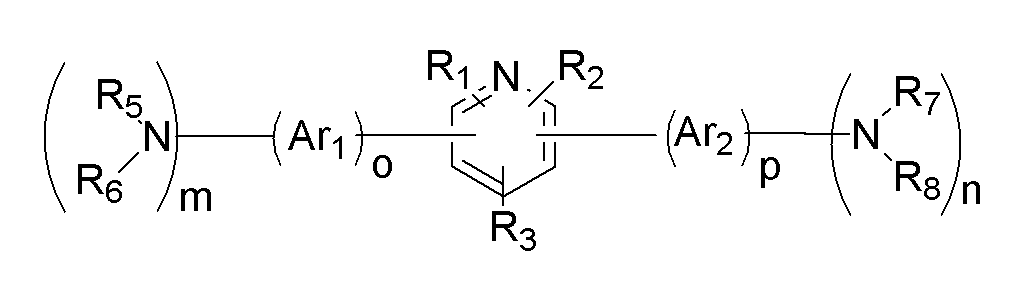
상기 목적을 달성하기 위하여, 본 발명의 일 구현예에 따르면, 하기 화학식 1로 표시되고, 분자 내에 정공수송기와 전자수송기를 동시에 가지는 바이폴라(bipolar) 유기화합물을 포함하는 유기광전소자용 재료를 제공한다.In order to achieve the above object, according to one embodiment of the present invention, a material for an organic photoelectric device, represented by the following formula (1), comprising a bipolar organic compound having a hole transporter and an electron transporter in a molecule at the same time .
[화학식 1][Formula 1]

(상기 화학식 1에서,(In the formula 1,
상기 HTU, 및 HTU'는 각각 독립적으로 정공수송기(hole transportation unit)이고,The HTU and HTU 'are each independently a hole transportation unit (hole transportation unit),
상기 R1 내지 R3는 각각 독립적으로 수소원자, 치환 또는 비치환된 탄소수 6 내지 30의 아릴기, 치환 또는 비치환된 탄소수 2 내지 30의 헤테로아릴기, 및 치환 또는 비치환된 탄소수 1 내지 30의 알킬기로 이루어진 군에서 선택되는 치환기이다)R 1 to R 3 are each independently a hydrogen atom, a substituted or unsubstituted aryl group having 6 to 30 carbon atoms, a substituted or unsubstituted heteroaryl group having 2 to 30 carbon atoms, and a substituted or unsubstituted carbon atom 1 to 30 Is a substituent selected from the group consisting of alkyl groups)
본 발명의 다른 일 구현예에 따르면, 양극과 음극 사이에 상기 유기광전소자용 재료를 함유한 유기 박막층을 포함하는 유기광전소자를 제공한다.According to another embodiment of the present invention, an organic photoelectric device including an organic thin film layer containing the organic photoelectric device material is provided between an anode and a cathode.
기타 본 발명의 구현예들의 구체적인 사항은 이하의 상세한 설명에 포함되어 있다.Other specific details of embodiments of the present invention are included in the following detailed description.
본 발명의 일 구현예에 따른 유기광전소자용 재료는 우수한 열적 안정성을 가지며, 정공과 전자를 모두 잘 전달할 수 있다.The material for an organic photoelectric device according to the exemplary embodiment of the present invention has excellent thermal stability and can transfer both holes and electrons well.
또한, 상기 유기광전소자용 재료를 이용하여 유기광전소자를 제조하는 경우, 낮은 구동전압에서도 높은 발광효율을 가지는 유기광전소자의 제조가 가능하다.In addition, when the organic photoelectric device is manufactured using the organic photoelectric device material, it is possible to manufacture the organic photoelectric device having a high luminous efficiency even at a low driving voltage.
이하, 본 발명의 일 구현예들을 상세히 설명하기로 한다. 다만, 이는 예시로서 제시되는 것으로, 이에 의해 본 발명이 제한되지는 않으며 본 발명은 후술할 청구범위의 범주에 의해 정의될 뿐이다. Hereinafter, one embodiment of the present invention will be described in detail. However, it should be understood that the present invention is not limited thereto, and the present invention is only defined by the scope of the following claims.
본 발명의 일 구현예에 따르면, 하기 화학식 1로 표시되고, 분자 내에 정공수송기와 전자수송기를 동시에 가지는 바이폴라(bipolar) 유기화합물을 포함하는 유기광전소자용 재료를 제공한다.According to one embodiment of the present invention, an organic photoelectric device material represented by the following Chemical Formula 1 and including a bipolar organic compound having both a hole transporter and an electron transporter in a molecule is provided.
[화학식 1][Formula 1]

(상기 화학식 1에서,(In the formula 1,
상기 HTU, 및 HTU'는 각각 독립적으로 정공수송기(hole transportation unit)이고,The HTU and HTU 'are each independently a hole transportation unit (hole transportation unit),
상기 R1 내지 R3는 각각 독립적으로 수소원자, 치환 또는 비치환된 탄소수 6 내지 30의 아릴기, 치환 또는 비치환된 탄소수 2 내지 30의 헤테로아릴기, 및 치환 또는 비치환된 탄소수 1 내지 30의 알킬기로 이루어진 군에서 선택되는 치환기이다)R 1 to R 3 are each independently a hydrogen atom, a substituted or unsubstituted aryl group having 6 to 30 carbon atoms, a substituted or unsubstituted heteroaryl group having 2 to 30 carbon atoms, and a substituted or unsubstituted carbon atom 1 to 30 Is a substituent selected from the group consisting of alkyl groups)
본 명세서에서 치환된 아릴기, 치환된 아릴렌기, 치환된 알킬기, 치환된 알킬렌기, 치환된 헤테로아릴기, 및 치환된 헤테로아릴렌기는 각각 독립적으로 탄소수 1 내지 30의 알킬기, 할로겐기, 탄소수 1 내지 30의 할로알킬기, 탄소수 6 내지 30의 아릴기, 또는 탄소수 2 내지 30의 헤테로아릴기로 치환된 아릴기, 아릴렌기, 알킬기, 알킬렌기, 헤테로아릴기, 및 헤테로아릴렌기를 의미한다.In the present specification, a substituted aryl group, substituted arylene group, substituted alkyl group, substituted alkylene group, substituted heteroaryl group, and substituted heteroarylene group are each independently an alkyl group having 1 to 30 carbon atoms, a halogen group and 1 carbon atom. An aryl group, an arylene group, an alkyl group, an alkylene group, a heteroaryl group, and a heteroarylene group substituted with a haloalkyl group having 30 to 30, an aryl group having 6 to 30 carbon atoms, or a heteroaryl group having 2 to 30 carbon atoms.
또한, 본 명세서에서 헤테로아릴기 또는 헤테로아릴렌기는 N, O, S, 및 P로 이루어진 군에서 선택되는 헤테로 원자를 한 고리 내에 1 내지 3개 함유하고, 나머 지는 탄소인 아릴기 또는 아릴렌기를 의미한다.In the present specification, the heteroaryl group or heteroarylene group contains 1 to 3 heteroatoms selected from the group consisting of N, O, S, and P in one ring, and the remaining aryl group or arylene group is carbon. it means.
상기 유기광전소자용 재료는 단독으로 사용할 수도 있고, 도펀트와 결합 가능한 호스트(host)물질로 사용할 수 있다. The organic photoelectric device material may be used alone or as a host material that can be combined with a dopant.
또한, 상기 화학식 1로 표시되는 바이폴라 유기화합물은 대칭 또는 비대칭일 수 있으며, 분자 내에 정공수송기와 전자수송기를 동시에 포함하고 있다. 상기 화학식 1로 표시되는 바이폴라 유기화합물에서 상기 피리딘기(pyridine; C6H5N)는 전자수송기로서 기능을 하고, 상기 HTU, 및 HTU'는 각각 독립적으로 정공수송기(hole transportation unit)를 나타내며, HTU와 HTU'는 서로 동일하거나 다를 수 있다.In addition, the bipolar organic compound represented by Formula 1 may be symmetrical or asymmetrical and includes both a hole transporter and an electron transporter in a molecule. In the bipolar organic compound represented by Chemical Formula 1, the pyridine group (C 6 H 5 N) functions as an electron transporter, and the HTU and HTU 'each independently represent a hole transport unit, HTU and HTU 'may be the same or different from each other.
상기 화학식 1로 표시되는 바이폴라 유기화합물을 하기 화학식 2로 표시되는 바이폴라 유기화합물인 것이 바람직하다.The bipolar organic compound represented by Chemical Formula 1 is preferably a bipolar organic compound represented by the following Chemical Formula 2.
[화학식 2][Formula 2]

(상기 화학식 2에서,(In Formula 2,
상기 X, 및 Y는 각각 독립적으로 질소원자, 황원자, 및 산소원자로 이루어진 군에서 선택되고, X and Y are each independently selected from the group consisting of a nitrogen atom, a sulfur atom, and an oxygen atom,
상기 Ar1, 및 Ar2는 각각 독립적으로 치환 또는 비치환된 탄소수 6 내지 30의 아릴기 또는 아릴렌기, 치환 또는 비치환된 탄소수 1 내지 30의 알킬기 또는 알킬렌기, 및 치환 또는 비치환된 탄소수 2 내지 30의 헤테로아릴기 또는 헤테로아릴 렌기로 이루어진 군에서 선택되고,Ar 1 and Ar 2 are each independently a substituted or unsubstituted aryl group or arylene group having 6 to 30 carbon atoms, a substituted or unsubstituted alkyl group or alkylene group having 1 to 30 carbon atoms, and a substituted or unsubstituted carbon number 2 It is selected from the group consisting of heteroaryl group or heteroaryl group of 30 to 30,
상기 R1 내지 R3은 각각 독립적으로 수소원자, 치환 또는 비치환된 탄소수 6 내지 30의 아릴기, 치환 또는 비치환된 탄소수 2 내지 30의 헤테로아릴기, 및 치환 또는 비치환된 탄소수 1 내지 30의 알킬기로 이루어진 군에서 선택되는 치환기이고,R 1 to R 3 are each independently a hydrogen atom, a substituted or unsubstituted aryl group having 6 to 30 carbon atoms, a substituted or unsubstituted heteroaryl group having 2 to 30 carbon atoms, and a substituted or unsubstituted carbon atom 1 to 30 A substituent selected from the group consisting of
상기 R5 내지 R8는 각각 독립적으로 수소원자, 치환 또는 비치환된 탄소수 6 내지 30의 아릴기 또는 아릴렌기, 치환 또는 비치환된 탄소수 2 내지 30의 헤테로아릴기 또는 헤테로아릴렌기, 및 치환 또는 비치환된 탄소수 1 내지 30의 알킬기 또는 알킬렌기로 이루어진 군에서 선택되고,R 5 to R 8 are each independently a hydrogen atom, a substituted or unsubstituted aryl group or arylene group having 6 to 30 carbon atoms, a substituted or unsubstituted heteroaryl group or heteroarylene group having 2 to 30 carbon atoms, and a substituted or It is selected from the group consisting of an unsubstituted alkyl group or alkylene group having 1 to 30 carbon atoms,
상기 R5와 R6는 각각 독립적인 치환기로 존재하거나, 서로 융합되어 고리를 형성하고, 상기 R7와 R8는 각각 독립적인 치환기로 존재하거나, 서로 융합되어 고리를 형성하고,R 5 and R 6 may each be present as independent substituents, or may be fused to each other to form a ring, and R 7 and R 8 may each be independently substituted, or may be fused to each other to form a ring,
상기 X가 황원자, 및 산소원자로 이루어진 군에서 선택되는 경우, R5 또는 R6 중 어느 하나는 비공유전자쌍을 나타내며, Y가 황원자, 및 산소원자로 이루어진 군에서 선택되는 경우, R7 또는 R8 중 어느 하나는 비공유전자쌍을 나타내고,When X is selected from the group consisting of a sulfur atom and an oxygen atom, any one of R 5 or R 6 represents a non-covalent electron pair, and when Y is selected from the group consisting of a sulfur atom and an oxygen atom, any of R 7 or R 8 One represents a lone pair,
상기 m과 n은 0 내지 3의 정수이고, m+n은 1 내지 6의 정수이고,M and n are integers of 0 to 3, m + n is an integer of 1 to 6,
상기 o와 p는 0 내지 2의 정수이다)O and p are integers from 0 to 2)
상기 화학식 2에서 Ar1의 측쇄에 연결된 치환기, Ar2의 측쇄에 연결된 치환 기는 각각 독립적으로 정공수송기로서 기능을 한다.In Formula 2, the substituents connected to the side chain of Ar 1 and the substituents connected to the side chain of Ar 2 independently function as hole transport groups.
상기 화학식 1로 표시되는 바이폴라 유기화합물은 하기 화학식 3으로 표시되는 바이폴라 유기화합물인 것이 바람직하다.The bipolar organic compound represented by Formula 1 is preferably a bipolar organic compound represented by Formula 3 below.
[화학식 3](3)
(상기 화학식 3에서,(In Chemical Formula 3,
상기 Ar1, 및 Ar2는 각각 독립적으로 치환 또는 비치환된 탄소수 6 내지 30의 아릴기 또는 아릴렌기, 치환 또는 비치환된 탄소수 1 내지 30의 알킬기 또는 알킬렌기, 및 치환 또는 비치환된 탄소수 2 내지 30의 헤테로아릴기 또는 헤테로아릴렌기로 이루어진 군에서 선택되고,Ar 1 and Ar 2 are each independently a substituted or unsubstituted aryl group or arylene group having 6 to 30 carbon atoms, a substituted or unsubstituted alkyl group or alkylene group having 1 to 30 carbon atoms, and a substituted or unsubstituted carbon number 2 To heteroaryl group or heteroarylene group of 30 to 30,
상기 R1 내지 R3은 각각 독립적으로 수소원자, 치환 또는 비치환된 탄소수 6 내지 30의 아릴기, 치환 또는 비치환된 탄소수 2 내지 30의 헤테로아릴기, 및 치환 또는 비치환된 탄소수 1 내지 30의 알킬기로 이루어진 군에서 선택되는 치환기이고,R 1 to R 3 are each independently a hydrogen atom, a substituted or unsubstituted aryl group having 6 to 30 carbon atoms, a substituted or unsubstituted heteroaryl group having 2 to 30 carbon atoms, and a substituted or unsubstituted carbon atom 1 to 30 A substituent selected from the group consisting of
상기 R5 내지 R8는 각각 독립적으로 수소원자, 치환 또는 비치환된 탄소수 6 내지 30의 아릴기 또는 아릴렌기, 치환 또는 비치환된 탄소수 2 내지 30의 헤테로아릴기 또는 헤테로아릴렌기, 및 치환 또는 비치환된 탄소수 1 내지 30의 알킬기 또는 알킬렌기로 이루어진 군에서 선택되고,R 5 to R 8 are each independently a hydrogen atom, a substituted or unsubstituted aryl group or arylene group having 6 to 30 carbon atoms, a substituted or unsubstituted heteroaryl group or heteroarylene group having 2 to 30 carbon atoms, and a substituted or It is selected from the group consisting of an unsubstituted alkyl group or alkylene group having 1 to 30 carbon atoms,
상기 R5와 R6는 각각 독립적인 치환기로 존재하거나, 서로 융합되어 고리를 형성하고, 상기 R7와 R8는 각각 독립적인 치환기로 존재하거나, 서로 융합되어 고리를 형성하고,R 5 and R 6 may each be present as independent substituents, or may be fused to each other to form a ring, and R 7 and R 8 may each be independently substituted, or may be fused to each other to form a ring,
상기 m과 n은 0 내지 3의 정수이고, m+n은 1 내지 6의 정수이고,M and n are integers of 0 to 3, m + n is an integer of 1 to 6,
상기 o와 p는 0 내지 2의 정수이다)O and p are integers from 0 to 2)
상기 화학식 3에서 각각 정공수송기로서 기능을 하는 Ar1의 측쇄에 연결된 치환기, 및 Ar2의 측쇄에 연결된 치환기는 각각 독립적으로 하기 화학식 4로 표시되는 치환기, 및 하기 화학식 5로 표시되는 치환기로 이루어진 군에서 선택되는 화합물인 것인 유기광전소자용 재료인 것이 바람직하다.The substituents connected to the side chain of Ar 1 and the substituents connected to the side chain of Ar 2 each independently function as a hole transport group in Formula 3, each independently a substituent represented by the following formula (4), and a group represented by the following formula (5) It is preferable that it is a material for organic photoelectric elements which is a compound chosen from.
[화학식 4][Formula 4]

(상기 화학식 4에 있어서,(In Formula 4,
상기 Ar', 및 Ar''는 각각 독립적으로 페닐기, 나프틸기, 안트릴기, 페난트릴기, 나프타센기, 피렌일기, 바이페닐일기, 터페닐일기, 톨릴기, 피롤기, 피라진일기, 피리미딜기, 피리다질기, 피리딘일기, 인돌릴기, 푸릴기, 벤조푸란일기, 퀴놀릴기, 퀴녹살린일기, 페난트리딘일기, 아크리딘일기, 페난트롤린일기, 페나진일 기, 페노티아진일기, 페녹사진일기, 옥사졸릴기, 옥사디아졸릴기, 및 티엔일기로 이루어진 군에서 선택되는 것이다)Ar 'and Ar' 'each independently represent a phenyl group, naphthyl group, anthryl group, phenanthryl group, naphthacene group, pyrenyl group, biphenylyl group, terphenylyl group, tolyl group, pyrrole group, pyrazinyl group, pyrimi Dyl group, pyridazyl group, pyridinyl group, indolyl group, furyl group, benzofuranyl group, quinolyl group, quinoxalinyl group, phenanthridinyl group, acridinyl group, phenanthrolineyl group, phenazinyl group, phenothiazineyl group , Phenoxazinyl group, oxazolyl group, oxadiazolyl group, and thienyl group)
[화학식 5][Chemical Formula 5]
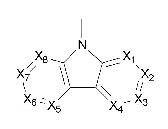
(상기 화학식 5에 있어서,(In Formula 5,
상기 X1 내지 X8은 각각 독립적으로 CR', 및 N로 이루어진 군에서 선택되고,X 1 to X 8 are each independently selected from the group consisting of CR ′ and N,
상기 R'는 각각 독립적으로 수소원자, 치환 또는 비치환된 탄소수 6 내지 30의 아릴기, 치환 또는 비치환된 탄소수 2 내지 30의 헤테로아릴기, 및 치환 또는 비치환된 탄소수 1 내지 30의 알킬기로 이루어진 군에서 선택되는 치환기이다)R 'is each independently a hydrogen atom, a substituted or unsubstituted aryl group having 6 to 30 carbon atoms, a substituted or unsubstituted heteroaryl group having 2 to 30 carbon atoms, and a substituted or unsubstituted alkyl group having 1 to 30 carbon atoms Is a substituent selected from the group consisting of
상기 화학식 1로 표시되는 바이폴라 유기화합물은 하기 화학식 6으로 표시되는 바이폴라 유기화합물인 것이 바람직하다.The bipolar organic compound represented by Formula 1 is preferably a bipolar organic compound represented by Formula 6 below.
[화학식 6][Formula 6]

(상기 화학식 6에서,(In Chemical Formula 6,
상기 Ar3, 및 Ar6은 각각 독립적으로 치환 또는 비치환된 탄소수 6 내지 30의 아릴기 또는 아릴렌기, 치환 또는 비치환된 탄소수 1 내지 30의 알킬기 또는 알킬렌기, 및 치환 또는 비치환된 탄소수 2 내지 30의 헤테로아릴기 또는 헤테로아릴렌기로 이루어진 군에서 선택되고,Ar 3 and Ar 6 are each independently a substituted or unsubstituted aryl group or arylene group having 6 to 30 carbon atoms, a substituted or unsubstituted alkyl group or alkylene group having 1 to 30 carbon atoms, and a substituted or unsubstituted carbon number 2 To heteroaryl group or heteroarylene group of 30 to 30,
상기 Ar4, 및 Ar5은 각각 독립적으로 치환 또는 비치환된 탄소수 6 내지 30의 아릴렌기, 치환 또는 비치환된 탄소수 1 내지 30의 알킬렌기, 및 치환 또는 비치환된 탄소수 2 내지 30의 헤테로아릴렌기로 이루어진 군에서 선택되고,Ar 4 and Ar 5 are each independently a substituted or unsubstituted arylene group having 6 to 30 carbon atoms, a substituted or unsubstituted alkylene group having 1 to 30 carbon atoms, and a substituted or unsubstituted heteroaryl having 2 to 30 carbon atoms. Is selected from the group consisting of Ren group,
상기 R1 내지 R3은 각각 독립적으로 수소원자, 치환 또는 비치환된 탄소수 6 내지 30의 아릴기, 치환 또는 비치환된 탄소수 2 내지 30의 헤테로아릴기, 및 치환 또는 비치환된 탄소수 1 내지 30의 알킬기로 이루어진 군에서 선택되는 치환기이고,R 1 to R 3 are each independently a hydrogen atom, a substituted or unsubstituted aryl group having 6 to 30 carbon atoms, a substituted or unsubstituted heteroaryl group having 2 to 30 carbon atoms, and a substituted or unsubstituted carbon atom 1 to 30 A substituent selected from the group consisting of
상기 R5 내지 R8는 각각 독립적으로 수소원자, 치환 또는 비치환된 탄소수 6 내지 30의 아릴기 또는 아릴렌기, 치환 또는 비치환된 탄소수 2 내지 30의 헤테로아릴기 또는 헤테로아릴렌기, 및 치환 또는 비치환된 탄소수 1 내지 30의 알킬기 또는 알킬렌기로 이루어진 군에서 선택되고,R 5 to R 8 are each independently a hydrogen atom, a substituted or unsubstituted aryl group or arylene group having 6 to 30 carbon atoms, a substituted or unsubstituted heteroaryl group or heteroarylene group having 2 to 30 carbon atoms, and a substituted or It is selected from the group consisting of an unsubstituted alkyl group or alkylene group having 1 to 30 carbon atoms,
상기 R5와 R6는 각각 독립적인 치환기로 존재하거나, 서로 융합되어 고리를 형성하고, 상기 R7와 R8는 각각 독립적인 치환기로 존재하거나, 서로 융합되어 고리를 형성하고,R 5 and R 6 may each be present as independent substituents, or may be fused to each other to form a ring, and R 7 and R 8 may each be independently substituted, or may be fused to each other to form a ring,
상기 m과 n은 0 내지 3의 정수이고, m+n은 1 내지 6의 정수이다)M and n are integers of 0 to 3, and m + n is an integer of 1 to 6)
상기 화학식 1로 표시되는 바이폴라 유기화합물은 하기 화학식 7로 표시되는 바이폴라 유기화합물인 것이 바람직하다.The bipolar organic compound represented by Formula 1 is preferably a bipolar organic compound represented by Formula 7.
[화학식 7][Formula 7]

(상기 화학식 7에서,(In Chemical Formula 7,
상기 R1 내지 R3은 각각 독립적으로 수소원자, 치환 또는 비치환된 탄소수 6 내지 30의 아릴기, 치환 또는 비치환된 탄소수 2 내지 30의 헤테로아릴기, 및 치환 또는 비치환된 탄소수 1 내지 30의 알킬기로 이루어진 군에서 선택되는 치환기이고,R 1 to R 3 are each independently a hydrogen atom, a substituted or unsubstituted aryl group having 6 to 30 carbon atoms, a substituted or unsubstituted heteroaryl group having 2 to 30 carbon atoms, and a substituted or unsubstituted carbon atom 1 to 30 A substituent selected from the group consisting of
상기 R5 내지 R10은 각각 독립적으로 수소원자, 치환 또는 비치환된 탄소수 6 내지 30의 아릴기 또는 아릴렌기, 치환 또는 비치환된 탄소수 2 내지 30의 헤테로아릴기 또는 헤테로아릴렌기, 및 치환 또는 비치환된 탄소수 1 내지 30의 알킬기 또는 알킬렌기로 이루어진 군에서 선택되고,R 5 to R 10 are each independently a hydrogen atom, a substituted or unsubstituted aryl group or arylene group having 6 to 30 carbon atoms, a substituted or unsubstituted heteroaryl group or heteroarylene group having 2 to 30 carbon atoms, and a substituted or It is selected from the group consisting of an unsubstituted alkyl group or alkylene group having 1 to 30 carbon atoms,
상기 R5와 R6 은 각각 독립적인 치환기로 존재하거나, 서로 융합되어 고리를 형성하고, 상기 R7과 R8는 각각 독립적인 치환기로 존재하거나, 서로 융합되어 고리를 형성하고, 상기 R9와 R10는 각각 독립적인 치환기로 존재하거나, 서로 융합되어 고리를 형성한다)R 5 and R 6 are each present as independent substituents or are fused to each other to form a ring, and R 7 and R 8 are each independently substituents or are fused to each other to form a ring, and R 9 and Each R 10 is present as an independent substituent or is fused to each other to form a ring)
상기 본 발명의 일 구현예에 따른 유기광전소자용 재료는 유리전이온도(Tg)가 120℃ 이상이며, 열분해온도(Td)가 400℃ 이상인 것이 바람직하다. 상기 유기광전소자용 재료가 유리전이온도(Tg)가 120℃ 이상이며, 열분해온도(Td)가 400℃ 이상인 경우, 유기광전소자에 사용되기에 충분한 열적 안정성을 가진다.The organic photoelectric device material according to the embodiment of the present invention preferably has a glass transition temperature (Tg) of 120 ° C. or more and a thermal decomposition temperature (Td) of 400 ° C. or more. When the organic photoelectric device material has a glass transition temperature (Tg) of 120 ° C. or higher and a thermal decomposition temperature (Td) of 400 ° C. or higher, the organic photoelectric device has sufficient thermal stability to be used in an organic photoelectric device.
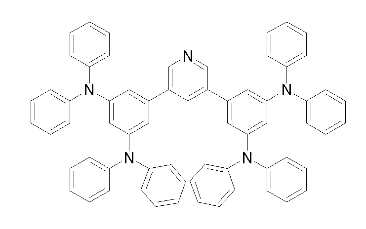
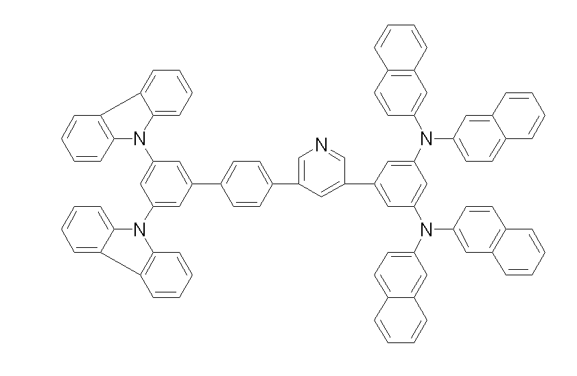
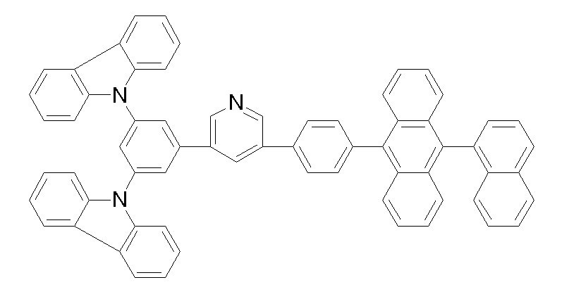
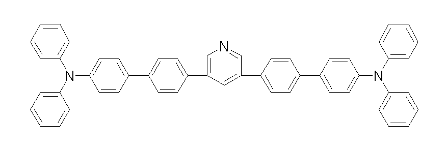
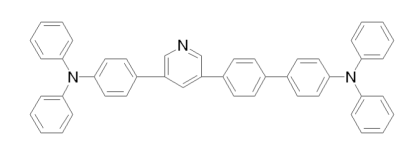
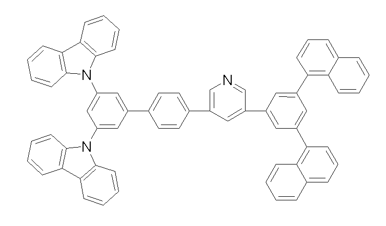
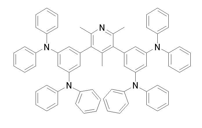
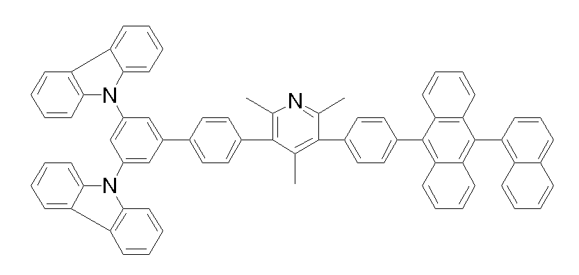
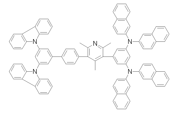
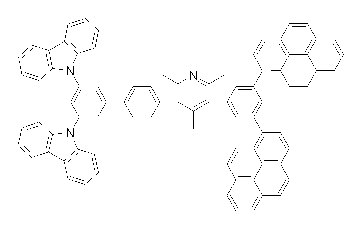
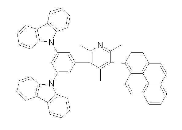
상기 화학식 1, 2, 3, 6, 및 7로 표시되는 바이폴라 유기화합물은 구체적으로 하기 화합물 1-1 내지 1-53으로 표시되는 바이폴라 유기화합물인 것이 더욱 바람직하다.More specifically, the bipolar organic compounds represented by Formulas 1, 2, 3, 6, and 7 are more preferably bipolar organic compounds represented by the following Compounds 1-1 to 1-53.
[화학식 1-1] [화학식 1-2][Formula 1-1] [Formula 1-2]

[화학식 1-3] [화학식 1-4][Formula 1-3] [Formula 1-4]


[화학식 1-5] [화학식 1-6][Formula 1-5] [Formula 1-6]


[화학식 1-7] [화학식 1-8][Formula 1-7] [Formula 1-8]


[화학식 1-9] [화학식 1-10][Formula 1-9] [Formula 1-10]


[화학식 1-11] [화학식 1-12][Formula 1-11] [Formula 1-12]


[화학식 1-13] [화학식 1-14][Formula 1-13] [Formula 1-14]


[화학식 1-15] [화학식 1-16][Formula 1-15] [Formula 1-16]

[화학식 1-17] [화학식 1-18][Formula 1-17] [Formula 1-18]

[화학식 1-19] [화학식 1-20][Formula 1-19] [Formula 1-20]

[화학식 1-21] [화학식 1-22][Formula 1-21] [Formula 1-22]

[화학식 1-23] [화학식 1-24][Formula 1-23] [Formula 1-24]


[화학식 1-25] [화학식 1-26][Formula 1-25] [Formula 1-26]

[화학식 1-27] [화학식 1-28][Formula 1-27] [Formula 1-28]

[화학식 1-29] [화학식 1-30][Formula 1-29] [Formula 1-30]


[화학식 1-31] [화학식 1-32][Formula 1-31] [Formula 1-32]


[화학식 1-33] [화학식 1-34][Formula 1-33] [Formula 1-34]


[화학식 1-35] [화학식 1-36][Formula 1-35] [Formula 1-36]


[화학식 1-37] [화학식 1-38][Formula 1-37] [Formula 1-38]


[화학식 1-39] [화학식 1-40][Formula 1-39] [Formula 1-40]
[화학식 1-41] [화학식 1-42][Formula 1-41] [Formula 1-42]


[화학식 1-43] [화학식 1-44][Formula 1-43] [Formula 1-44]
[화학식 1-45] [화학식 1-46][Formula 1-45] [Formula 1-46]


[화학식 1-47] [화학식 1-48][Formula 1-47] [Formula 1-48]


[화학식 1-49] [화학식 1-50][Formula 1-49] [Formula 1-50]


[화학식 1-51] [화학식 1-52][Formula 1-51] [Formula 1-52]


[화학식 1-53][Formula 1-53]

상기 화학식 1로 표시되는 바이폴라 유기화합물은 발광층, 전자수송층, 전자주입층, 정공수송층, 정공주입층, 정공저지층, 및 이들의 조합으로 이루어진 군에서 선택되는 층에 포함될 수 있다.The bipolar organic compound represented by Chemical Formula 1 may be included in a layer selected from the group consisting of a light emitting layer, an electron transport layer, an electron injection layer, a hole transport layer, a hole injection layer, a hole blocking layer, and a combination thereof.
상기 화학식 1로 표시되는 바이폴라 유기화합물이 전자수송층, 전자주입층, 정공수송층, 정공주입층, 또는 정공저지층에 포함되는 경우 단독으로 사용하는 것도 가능하고, 발광층에 포함되는 경우 도펀트와 결합할 수 있는 호스트(host) 재료로 사용될 수도 있다.When the bipolar organic compound represented by Chemical Formula 1 is included in the electron transport layer, the electron injection layer, the hole transport layer, the hole injection layer, or the hole blocking layer, it may be used alone, or may be combined with the dopant when included in the emission layer. It can also be used as a host material.
도펀트(dopant)란 그 자체는 발광능력이 높은 화합물로서 호스트에 미량 혼합해서 사용하기 때문에 이를 게스트(guest) 또는 도펀트(dopant)라고 한다.A dopant is a guest or dopant because it is a compound having a high luminous ability and used in a small amount in a host.
즉, 도펀트는 호스트 물질에 도핑(doping)되어 발광을 일으키는 물질로서, 일반적으로 3중항 상태 이상으로 여기시키는 다중항 여기(multiplet excitation)에 의해 발광하는 금속 착체(metal complex)와 같은 물질이 사용된다.That is, the dopant is a material that emits light by doping the host material, and generally, a material such as a metal complex that emits light by multiplet excitation that excites above a triplet state is used. .
상기 화학식 1의 화합물이 발광 호스트 물질로 사용될 때, 함께 사용될 수 있는 도펀트로는 적색(R), 녹색(G), 청색(B), 및 백색(W)으로 이루어진 군에서 선택되는 인광 또는 형광 도펀트 물질이 모두 사용가능하나, 인광 도펀트 물질을 사용하는 바람직하며, 기본적으로 발광양자효율이 높을 것, 잘 응집되지 않을 것, 호스트 재료 속에 균일하게(uniformly) 분포될 것이라는 성질을 만족시킬 수 있는 물질이어야 한다.When the compound of Formula 1 is used as a light emitting host material, a dopant that may be used together may be a phosphorescent or fluorescent dopant selected from the group consisting of red (R), green (G), blue (B), and white (W). Although all materials can be used, it is preferable to use a phosphorescent dopant material, and it must be a material that satisfies the property of high luminescence quantum efficiency, poor coagulation, and uniform distribution in the host material. do.
상기 인광 도펀트는 Ir, Pt, Os, Ti, Zr, Hf, Eu, Tb, Tm, 및 이들의 혼합물로 이루어진 군에서 선택된 원소를 포함하는 유기 금속화합물인 것이 바람직하다.The phosphorescent dopant is preferably an organometallic compound containing an element selected from the group consisting of Ir, Pt, Os, Ti, Zr, Hf, Eu, Tb, Tm, and mixtures thereof.
구체적인 예로, 적색 인광 도펀트로는 PtOEP(platinum octaethylporphin), Ir(Piq)2(acac)(여기에서, Piq는 1-페닐이소퀴놀린이고, acac는 펜탄-2,4-디온이다), Ir(Piq)3, RD 61(UDC사) 등을 사용할 수 있으며, 녹색 인광 도펀트로는 Ir(PPy)2(acac)(여기에서 PPy는 2-페닐피리딘이다), Ir(PPy)3, GD48(UDC사) 등을 사용할 수 있으며, 청색 인광 도펀트로는 (4,6-F2PPy)2Irpic(Applied Physics Letters, 79, 2082-2084, 2001 참조)등을 사용할 수 있다.As a specific example, red phosphorescent dopants include platinum octaethylporphin (PtOEP), Ir (Piq) 2 (acac), where Piq is 1-phenylisoquinoline, acac is pentane-2,4-dione, and Ir (Piq). ) 3, and the like RD 61 (UDC Co.), a green phosphorescent dopant Ir (PPy) 2 (acac) ( here PPy is 2-phenylpyridine), Ir (PPy) 3, GD48 (UDC Co. ) And (4,6-F 2 PPy) 2 Irpic (see Applied Physics Letters, 79, 2082-2084, 2001) may be used as the blue phosphorescent dopant.
본 발명의 다른 일 구현예에 따르면 양극과 음극 사이에 상기 유기광전소자용 재료를 함유한 유기 박막층을 포함하는 유기광전소자를 제공한다. 상기 유기광전소자는 유기전기발광소자인 것이 바람직하다.According to another embodiment of the present invention provides an organic photoelectric device comprising an organic thin film layer containing the material for the organic photoelectric device between the anode and the cathode. The organic photoelectric device is preferably an organic electroluminescent device.
이하, 첨부한 도면을 참고로 하여 본 발명의 일 구현예에 대하여 본 발명이 속하는 기술 분야에서 통상의 지식을 가진 자가 용이하게 실시할 수 있도록 상세히 설명한다. 본 발명은 여러 가지 상이한 형태로 구현될 수 있으며 여기에서 설명하는 일 구현예에 한정되지 않는다.Hereinafter, exemplary embodiments of the present invention will be described in detail with reference to the accompanying drawings so that those skilled in the art may easily implement the present invention. As those skilled in the art would realize, the described embodiments may be modified in various different ways, all without departing from the spirit or scope of the present invention.
도 1 내지 도 5는 본 발명의 일 구현예들에 따른 유기광전소자용 재료를 이용하여 제조될 수 있는 유기광전소자에 대한 다양한 구현예들을 나타내는 단면도이다.1 to 5 are cross-sectional views illustrating various embodiments of an organic photoelectric device that may be manufactured using a material for an organic photoelectric device according to embodiments of the present invention.
도 1 내지 도 5를 참조하면, 본 발명의 일 구현예에 따른 유기광전소자(100, 200, 300, 400, 및 500)는 양극(120)과 음극(110)을 사이에 두고 게재되는 한층 이상의 유기 박막층(105)을 포함하는 구조로 되어 있으며, 양극(120)에는 ITO(indium tin oxide) 투명전극을, 음극(110)에는 알루미늄 등과 같은 금속전극을 사용할 수 있다.1 to 5, the organic
먼저, 도 1을 참조하면, 도 1은 유기 박막층(105)으로서 발광층(130)만이 존재하는 유기광전소자(100)를 나타내고 있다.First, referring to FIG. 1, FIG. 1 illustrates an organic
도 2를 참조하면, 도 2에서는 유기박막층(105)으로서 전자수송층(미도시)을 포함하는 발광층(230)과 정공수송층(140)이 존재하는 2층형 유기광전소자(200)를 나타내고 있다. 상기 정공수송층(140)은 ITO와 같은 투명전극과의 접합성이나 정공수송성이 우수한 막으로 이루어진 별도의 층이다.Referring to FIG. 2, FIG. 2 illustrates a two-layered organic
도 3을 참조하면, 도 3에서는 유기박막층(105)으로서 전자수송층(150), 발광층(130), 정공수송층(140)이 존재하는 3층형 유기광전소자(300)로서, 발광층(130)이 독립된 형태로 되어 있고, 전자수송성이나 정공수송성이 우수한 막을 별도의 층 으로 쌓은 형태를 나타내고 있다.Referring to FIG. 3, in FIG. 3, the three-layer organic
도 4를 참조하면, 도 4에서는 유기박막층(105)으로서 전자주입층(160), 발광층(130), 정공수송층(140), 정공주입층(170)이 존재하는 4층형 유기광전소자(400)로서, 상기 도 3에 도시된 3층형 유기광전소자(300)가 가지는 특징에 양극으로 사용되는 ITO와의 접합성을 생각하여 정공주입층(170)이 추가된 형태를 타내고 있다.Referring to FIG. 4, in FIG. 4, a four-layered organic
도 5를 참조하면, 도 5에서는 유기박막층(105)으로서 전자주입층(160), 전자수송층(150), 발광층(130), 정공수송층(140), 정공주입층(170)과 같은 각기 다른 기능을 하는 5개의 층이 존재하는 5층형 유기광전소자(500)를 나타내고 있으며, 상기 유기광전소자(500)는 전자주입층(160)을 별도로 형성하여 저전압화에 효과적인 특징이 있다.Referring to FIG. 5, in FIG. 5, different functions such as an
상기에서 설명한 1층 내지 5층으로 되어 있는 유기박막층(105)을 형성하기 위해서는, 진공증착법(evaporation), 스퍼터링(sputtering), 플라즈마 도금, 및 이온도금과 같은 건식성막법과 스핀코팅(spin coating), 침지법(dipping), 유동코팅법(flow coating)과 같은 습식성막법 등과 같은 공정이 사용될 수 있다.In order to form the organic
본 발명의 일 구현예에 따른 유기광전소자에서 상기 발광층, 전자수송층 및/또는 전자주입층, 정공수송층 및/또는 정공주입층, 정공저지층 중 적어도 한 층은 상기 화학식 1로 표시되는 바이폴라 유기화합물을 포함하는 것이 바람직하다.In the organic photoelectric device according to the embodiment of the present invention, at least one of the light emitting layer, the electron transport layer and / or the electron injection layer, the hole transport layer and / or the hole injection layer, and the hole blocking layer is a bipolar organic compound represented by Chemical Formula 1 It is preferable to include.
또한, 상기 유기박막층(105)은 인광 발광성 화합물을 함유하는 것이 바람직한데, 이러한 인광 발광성 화합물로서는, 3중항 상태 이상으로 여기시키는 다중항 여기(multiplet excitation)에 의해 발광하는 금속 착체 등이 바람직하다.The organic
이하에서는 본 발명의 일 구현예에 따른 유기광전소자용 재료를 제조하기 위한 구체적인 방법과 이러한 방법을 이용하여 제조된 유기광전소자용 재료를 이용하여 실제 유기광전소자를 제조하였을 경우 발광효율이 높고, 구동전압이 낮아지게 된다는 것을 구체적인 실시예, 및 비교예를 들어 설명한다. 다만, 여기에 기재되지 않은 내용은 이 기술 분야에서 숙련된 자이면 충분히 기술적으로 유추할 수 있는 것이므로 그 설명을 생략한다.Hereinafter, a specific method for manufacturing an organic photoelectric device material according to an embodiment of the present invention and a high luminous efficiency when the actual organic photoelectric device is manufactured using the organic photoelectric device material manufactured using the method, It will be described with reference to specific examples and comparative examples that the driving voltage is lowered. However, the content not described herein is omitted because it can be inferred technically sufficient by those skilled in the art.
(( 실시예Example 1: One: 유기광전소자용For organic photoelectric device 재료의 합성) Synthesis of materials)
(( 실시예Example 1-1: 화합물(16)의 합성) 1-1: Synthesis of Compound (16))
하기 화합물(16)을 하기 반응식 1과 같은 6단계 경로를 통해 합성하였다.The following compound (16) was synthesized through a 6 step route as in Scheme 1 below.
[반응식 1]Scheme 1

제1 단계; 중간체 생성물(A)의 합성First step; Synthesis of Intermediate Product (A)
카바졸 40.4g(241mmol), 1,3,5-트리브로모벤젠 38.0g(121mmol), 염화제일구리 2.99g(30 mmol), 및 탄산칼륨 66.7g(483mmol)을 디메틸술폭사이드 171ml에 현탁하여, 질소 분위기 하에서 8시간 가열 환류하였다.40.4 g (241 mmol) of carbazole, 38.0 g (121 mmol) of 1,3,5-tribromobenzene, 2.99 g (30 mmol) of cuprous chloride, and 66.7 g (483 mmol) of potassium carbonate were suspended in 171 ml of dimethyl sulfoxide. It heated and refluxed for 8 hours in nitrogen atmosphere.
상기 가열 환류시킨 반응용액을 실온까지 냉각하고, 메탄올을 사용하여 재결정시켰다. 석출한 결정을 여과에 의해 분리하고, 수득한 잔류물을 실리카겔 컬럼 크로마토그래피로 정제하여, 결정 상태의 중간체 생성물(A) 36.7g(수율62.4%)을 수득하였다.The heated and refluxed reaction solution was cooled to room temperature and recrystallized with methanol. The precipitated crystals were separated by filtration, and the obtained residue was purified by silica gel column chromatography to obtain 36.7 g (yield 62.4%) of the intermediate product (A) in the crystalline state.
제2 단계; 중간체 생성물(B)의 합성Second step; Synthesis of Intermediate Product (B)
중간체 생성물(A) 35.0g(72mmol)을 테트라히드로푸란 350ml에 용해하고, 아르곤 분위기하의 -70oC에서 n-부틸리튬 헥산 용액(1.6M) 61.5ml(98mmol)을 가하여, 수득된 용액을 -70oC 내지 40oC에서 1시간 교반했다. 상기 교반한 반응용액을 -70oC까지 냉각한 후, 이소프로필테트라메틸디옥사보로란 29.3ml(144mmol)를 서서히 적가하였다. 수득된 용액을 -70oC에서 1시간 교반한 후, 실온까지 승온시켜 6시간 동안 교반했다. 수득된 반응용액에 물 200ml를 첨가한 다음 20분간 교반하였다.35.0 g (72 mmol) of the intermediate product (A) were dissolved in 350 ml of tetrahydrofuran, and 61.5 ml (98 mmol) of n-butyllithium hexane solution (1.6 M) was added at -70 o C under argon atmosphere, to thereby obtain a-solution. It stirred at 70 degreeC- 40 degreeC for 1 hour. The stirred reaction solution was cooled to −70 ° C., and then 29.3 ml (144 mmol) of isopropyltetramethyldioxaborolane was slowly added dropwise. The resulting solution was stirred at -70 ° C. for 1 hour, then warmed to room temperature and stirred for 6 hours. 200 ml of water was added to the obtained reaction solution, followed by stirring for 20 minutes.
상기 교반한 반응용액을 2개의 액체층으로 분리한 후, 유기층을 무수황산나트륨으로 건조했다. 상기 건조한 반응용액에서 감압하여 유기용매를 제거한 후, 수득한 잔류물을 실리카겔 컬럼 크로마토그래피로 정제하여, 결정 상태의 중간체 생성물(B) 25.1g(수율65.4%)을 수득했다.The stirred reaction solution was separated into two liquid layers, and then the organic layer was dried over anhydrous sodium sulfate. After the organic solvent was removed under reduced pressure in the dried reaction solution, the obtained residue was purified by silica gel column chromatography to obtain 25.1 g (yield 65.4%) of the intermediate product (B) in the crystalline state.
제3 단계; 중간체 생성물(C)의 합성Third step; Synthesis of Intermediate Product (C)
중간체 생성물(B) 45.1g(84mmol), 3,5-디브로모피리딘 20.0g(84mmol), 및 테트라키스-(트리페닐포스핀)팔라듐 2.44g(2.1mmol)을 테트라히드로푸란 600ml, 및 톨루엔 400ml에 현탁하고, 탄산칼륨 23.3g(169mmol)을 물 400ml에 용해한 용액을 이 현탁액에 가하고, 수득된 혼합물을 9시간 가열 환류하였다. 상기 가열 환류한 반응용액을 2층으로 분리한 후, 유기층을 염화 나트륨 포화수용액으로 세정하고, 무수 황산나트륨으로 건조했다.45.1 g (84 mmol) of intermediate product (B), 20.0 g (84 mmol) of 3,5-dibromopyridine, and 2.44 g (2.1 mmol) of tetrakis- (triphenylphosphine) palladium 600 ml of tetrahydrofuran, and toluene It was suspended in 400 ml, a solution of 23.3 g (169 mmol) of potassium carbonate dissolved in 400 ml of water was added to this suspension, and the obtained mixture was heated to reflux for 9 hours. After separating the heated and refluxed reaction solution into two layers, the organic layer was washed with saturated aqueous sodium chloride solution and dried over anhydrous sodium sulfate.
상기 건조한 반응용액에서 유기용매를 감압 증류하여 제거한 후, 그 잔류물을 톨루엔으로 재결정하여, 석출한 결정을 여과에 의해 분리하고, 톨루엔으로 세정하여, 결정 상태의 중간체 생성물(C) 30.7g(64.4%)을 수득했다.The organic solvent was distilled off under reduced pressure in the dried reaction solution, the residue was recrystallized with toluene, the precipitated crystals were separated by filtration, washed with toluene, and 30.7 g (64.4) of the intermediate product (C) in the crystalline state. %) Was obtained.
제4 단계; 중간체 생성물(D)의 합성A fourth step; Synthesis of Intermediate Product (D)
9, 10- 디브로모벤젠 10g(30mmol), 1-나프탈렌보론산 7.6g(30mmol), 및 테트라키스-(트리페닐포스핀)팔라듐 1.73g(1.5mmol)을 톨루엔 500ml에 현탁하고, 탄산칼륨 4.14g(30mmol)을 물 60ml에 용해한 용액을 이 현탁액에 가하고, 수득된 혼합물을 9시간 가열 환류하였다.10 g (30 mmol) of 9,10-dibromobenzene, 7.6 g (30 mmol) of 1-naphthalene boronic acid, and 1.73 g (1.5 mmol) of tetrakis- (triphenylphosphine) palladium were suspended in 500 ml of toluene, followed by potassium carbonate. A solution of 4.14 g (30 mmol) dissolved in 60 ml of water was added to this suspension, and the obtained mixture was heated to reflux for 9 hours.
상기 가열 환류한 반응용액을 2층으로 분리한 후, 유기층을 염화 나트륨 포화수용액으로 세정하고, 무수 황산나트륨으로 건조했다. 상기 건조한 반응용액에서 유기용매를 감압 증류하여 제거한 후, 그 잔류물을 톨루엔으로 재결정하여, 석출한 결정을 여과에 의해 분리하고, 톨루엔으로 세정하여, 결정 상태의 중간체 생성물(D) 5.97g(52%)을 수득했다.After separating the heated and refluxed reaction solution into two layers, the organic layer was washed with saturated aqueous sodium chloride solution and dried over anhydrous sodium sulfate. The organic solvent was distilled off under reduced pressure in the dried reaction solution, the residue was recrystallized with toluene, the precipitated crystals were separated by filtration, washed with toluene, and 5.97 g (52) of an intermediate (D) in the crystalline state. %) Was obtained.
제5 단계; 중간체 생성물(E)의 합성A fifth step; Synthesis of Intermediate Product (E)
중간체 생성물(D) 5g(13mmol)을 테트라히드로푸란 350ml에 용해하고, 아르곤 분위기하의 -70oC에서 n-부틸리튬 헥산 용액(1.6M) 8.12(13mmol)을 가하고, 수득된 용액을 -70oC 내지 40oC에서 1시간 동안 교반했다. 상기 교반하여 얻어진 반응용액을 -70oC까지 냉각한 후, 이소프로필테트라메틸디옥사보로란 2.41g(13mmol)를 서서 히 적가하였다. 수득된 반응용액을 -70oC에서 1시간 교반한 후, 실온까지 승온시켜 6시간 교반했다. 수득된 반응용액에 물 200ml를 첨가한 다음 20분간 교반했다.5 g (13 mmol) of the intermediate product (D) were dissolved in 350 ml of tetrahydrofuran, n-butyllithium hexane solution (1.6 M) 8.12 (13 mmol) was added at -70 o C under argon atmosphere, and the resulting solution was -70 o. Stirred at C-40 o C for 1 h. The reaction solution obtained by stirring was cooled to −70 ° C., and then 2.41 g (13 mmol) of isopropyl tetramethyldioxaborolane was added dropwise. The resulting reaction solution was stirred at −70 ° C. for 1 hour, and then heated to room temperature and stirred for 6 hours. 200 ml of water was added to the obtained reaction solution, followed by stirring for 20 minutes.
상기 교반한 반응용액을 2개의 액체층으로 분리한 후, 유기층을 무수황산나트륨으로 건조했다. 상기 건조한 반응용액에서 감압하여 유기용매를 제거한 후, 수득한 잔류물을 실리카겔 컬럼 크로마토그래피로 정제하여, 결정 상태의 중간체 생성물(E) 3.5g(수율60%)을 수득했다.The stirred reaction solution was separated into two liquid layers, and then the organic layer was dried over anhydrous sodium sulfate. After the organic solvent was removed under reduced pressure in the dried reaction solution, the obtained residue was purified by silica gel column chromatography to obtain 3.5 g (60%) of an intermediate product (E) in crystalline state.
제6 단계; 화합물 (16)의 합성Sixth step; Synthesis of Compound (16)
중간체 생성물(C) 3g(5.3mmol), 중간체 생성물(E) 2.28(5.3mmol), 및 테트라키스-(트리페닐포스핀)팔라듐 0.3g(0.26mmol)을 테트라히드로푸란 100ml, 및 톨루엔 100ml에 현탁하고, 탄산칼륨 0.73g(5.3mmol)을 물 100ml에 용해한 용액을 이 현탁액에 가하고, 수득된 혼합물을 9시간 가열 환류하였다. 상기 가열 환류한 반응용액을 2층으로 분리한 후, 유기층을 염화 나트륨 포화수용액으로 세정하고, 무수 황산나트륨으로 건조했다.3 g (5.3 mmol) of intermediate product (C), 2.28 (5.3 mmol) of intermediate product (E), and 0.3 g (0.26 mmol) of tetrakis- (triphenylphosphine) palladium are suspended in 100 ml of tetrahydrofuran and 100 ml of toluene. Then, a solution obtained by dissolving 0.73 g (5.3 mmol) of potassium carbonate in 100 ml of water was added to this suspension, and the obtained mixture was heated to reflux for 9 hours. After separating the heated and refluxed reaction solution into two layers, the organic layer was washed with saturated aqueous sodium chloride solution and dried over anhydrous sodium sulfate.
상기 건조한 반응용액에서 유기용매를 감압 증류하여 제거한 후, 그 잔류물을 톨루엔으로 재결정하여, 석출한 결정을 여과에 의해 분리하고, 톨루엔으로 세정하여, 결정 상태의 화합물(16) 2.21g(53%)을 수득했다.The organic solvent was distilled off under reduced pressure in the dried reaction solution, and the residue was recrystallized with toluene, and the precipitated crystals were separated by filtration and washed with toluene to obtain 2.21 g (53%) of the compound (16) in the crystalline state. ) Was obtained.
(( 실시예Example 1-2: 화합물(24)의 합성)1-2: Synthesis of Compound (24))
하기 화합물(24)를 하기 반응식 2과 같은 경로를 통해 합성하였다.Compound (24) was synthesized through the same route as in Scheme 2 below.
[반응식 2]Scheme 2
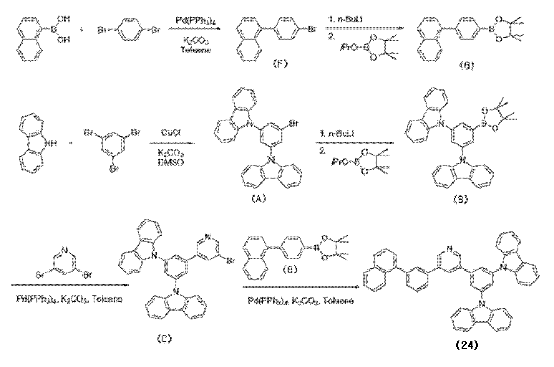
제1 단계; 중간체 생성물(F)의 합성First step; Synthesis of Intermediate Product (F)
1,3-디브로모벤젠 15g(63mmol), 1-나프탈렌보론산 7.66g(44mmol), 탄산칼륨 17.58g(127mmol), 및 테트라키스-(트리페닐포스핀)팔라듐 1.83g(50mmol)를 테트라하이드로푸란 200ml, 톨루엔 200ml, 및 정제수(50ml)에 현탁하여, 질소 분위기하에서 24시간 가열 환류하였다.15 g (63 mmol) of 1,3-dibromobenzene, 7.66 g (44 mmol) of 1-naphthalene boronic acid, 17.58 g (127 mmol) of potassium carbonate, and 1.83 g (50 mmol) of tetrakis- (triphenylphosphine) palladium It was suspended in 200 ml of hydrofuran, 200 ml of toluene, and purified water (50 ml) and heated to reflux for 24 hours in a nitrogen atmosphere.
상기 가열 환류한 반응용액을 실온까지 냉각하고, 상기 반응용액을 2층으로 분리한 후, 유기층의 용매를 감압하여 제거한 후 얻은 유체를 관크로마토그래피(헥산)로 분리한 후, 용매를 제거하여 겔 상태의 중간체 생성물(F) 15g(83%)을 수득했다.The heated and refluxed reaction solution was cooled to room temperature, the reaction solution was separated into two layers, the solvent of the organic layer was removed under reduced pressure, and the obtained fluid was separated by tube chromatography (hexane), and then the solvent was removed to remove the gel. 15 g (83%) of intermediate product (F) in the state was obtained.
제2 단계; 중간체 생성물(G)의 합성Second step; Synthesis of Intermediate Product (G)
중간체 생성물(F) 7g(24mmol)을 테트라하이드로푸란 50ml에 용해하고, 아르곤 분위기하의 -70oC에서 n-부틸리튬 헥산 용액(1.6M) 15ml(24mmol)을 가하여 수득된 용액을 -70oC에서 30분간 교반 후, 반응용액에 이소프로필테트라메틸디옥사보로란 47.9ml(235mmol)을 천천히 적가하였다. 수득된 반응용액을 -70oC에서 1시간 교반한 후, 실온까지 승온시켜 6시간 교반했다. 수득된 반응용액에 물 200ml를 첨가한 다음 20분간 교반했다.Dissolve 7 g (24 mmol) of the intermediate product (F) in 50 ml of tetrahydrofuran and add 15 ml (24 mmol) of n-butyllithium hexane solution (1.6 M) at -70 o C under argon atmosphere to -70 o C. After 30 minutes of stirring, 47.9 ml (235 mmol) of isopropyltetramethyldioxaborolane was slowly added dropwise to the reaction solution. The resulting reaction solution was stirred at −70 ° C. for 1 hour, and then heated to room temperature and stirred for 6 hours. 200 ml of water was added to the obtained reaction solution, followed by stirring for 20 minutes.
상기 교반한 반응용액을 2개의 액체층으로 분리한 후 감압하여 유기용매를 제거한 후, 수득한 잔류물을 실리카겔 관크로마토그래피로 정제하여, 중간체 생성물(G) 6g(73%)을 수득했다.The stirred reaction solution was separated into two liquid layers and then decompressed to remove the organic solvent, and the obtained residue was purified by silica gel column chromatography to obtain 6 g (73%) of an intermediate product (G).
제3 단계; 화합물(24)의 합성Third step; Synthesis of Compound (24)
중간체 생성물(C) 4g(7mmol), 중간체 생성물(G) 2.81g(8.5mmol), 탄산칼륨1.96g(14mmol), 및 테트라키스-(트리페닐포스핀)팔라듐 0.41g(0.3mmol)을 톨루엔 200ml, 테트라하이드로푸란 200ml, 및 정제수(50ml)에 현탁하여 24시간 가열 교반하였다.200 g of toluene in 4 g (7 mmol) of intermediate product (C), 2.81 g (8.5 mmol) of intermediate product (G), 1.96 g (14 mmol) of potassium carbonate, and 0.41 g (0.3 mmol) of tetrakis- (triphenylphosphine) palladium It was suspended in 200 ml of tetrahydrofuran and purified water (50 ml) and stirred with heating for 24 hours.
상기 가열 교반한 반응용액에서 반응온도를 실온까지 냉각하고, 2층으로 분리한 후, 유기층의 용매를 감압 제거하여 수득한 잔유물을 실리카겔 컬럼 크로마토그래피로 정제하여 화합물(24) 4g(82%)을 수득했다.After the reaction temperature was cooled to room temperature in the reaction mixture, which was stirred with heat, and then separated into two layers, the residue obtained by depressurizingly removing the solvent of the organic layer was purified by silica gel column chromatography to obtain 4 g (82%) of Compound (24). Obtained.
(실시예 1-3: 화합물(26)의 합성)Example 1-3 Synthesis of Compound (26)
하기 화합물(26)을 하기 반응식 3과 같은 경로를 통해 합성하였다.Compound (26) was synthesized through the same route as in Scheme 3 below.
[반응식 3]Scheme 3

중간체 생성물(C) 3g(5.3mmol), 파이렌-1-보론산 1.3g(5.3mmol), 및 테트라키스-(트리페닐포스핀)팔라듐 0.3g(0.2mmol)을 테트라히드로푸란 150ml, 및 톨루엔 150ml에 현탁하고, 탄산칼륨 1.38g(10mmol)을 물 20ml에 용해한 용액을 현탁액에 가하여 수득된 혼합물을 9시간 가열 환류하였다. 3 g (5.3 mmol) of intermediate product (C), 1.3 g (5.3 mmol) of pyrene-1-boronic acid, and 0.3 g (0.2 mmol) of tetrakis- (triphenylphosphine) palladium, 150 ml of tetrahydrofuran, and toluene The resulting mixture was suspended in 150 ml and a solution obtained by dissolving 1.38 g (10 mmol) of potassium carbonate in 20 ml of water was added to the suspension, and the resulting mixture was heated to reflux for 9 hours.
상기 가열 환류한 반응용액을 2층으로 분리한 후, 유기층을 염화 나트륨 포화수용액으로 세정하고, 무수 황산나트륨으로 건조했다. 상기 건조한 반응용액에서 유기용매를 감압 증류하여 제거한 후, 그 잔류물을 톨루엔으로 재결정하여, 석출한 결정을 여과에 의해 분리하고, 톨루엔으로 세정하여, 결정 상태의 화합물(26) 2.73g(75%)을 수득했다.After separating the heated and refluxed reaction solution into two layers, the organic layer was washed with saturated aqueous sodium chloride solution and dried over anhydrous sodium sulfate. The organic solvent was distilled off under reduced pressure in the dried reaction solution, and the residue was recrystallized with toluene, and the precipitated crystals were separated by filtration and washed with toluene to obtain 2.73 g (75%) of the compound (26) in the crystalline state. ) Was obtained.
(실시예 1-4: 화합물(51)의 합성)Example 1-4: Synthesis of Compound (51)
하기 화합물(51)을 하기 반응식 4와 같은 경로를 통해 합성하였다.Compound (51) was synthesized through the same route as in Scheme 4 below.
[반응식 4]Scheme 4

제1 단계; 중간체 생성물(H)의 합성First step; Synthesis of Intermediate Product (H)
3,6-디브로모벤젠 3g(9mmol), 벤젠보론산 2.25g(18mmol), 탄산칼륨 5g(36mmol), 및 테트라키스-(트리페닐포스핀)팔라듐 0.2g(0.18mmol)를 톨루엔 200ml, 및 정제수(50ml)에 현탁하여, 질소 분위기하에서 24시간 가열 환류하였다.3 g (9 mmol) of 3,6-dibromobenzene, 2.25 g (18 mmol) of benzeneboronic acid, 5 g (36 mmol) of potassium carbonate, and 0.2 g (0.18 mmol) of tetrakis- (triphenylphosphine)
상기 가열 환류한 반응용액을 2층으로 분리한 후, 유기층을 염화 나트륨 포화수용액으로 세정하고, 무수 황산나트륨으로 건조했다. 상기 건조한 반응용액에서 유기용매를 감압 증류하여 제거한 후, 그 잔류물을 톨루엔으로 재결정하여, 석출한 결정을 여과에 의해 분리하고, 톨루엔으로 세정하여, 결정 상태의 중간체 생성물(H) 1.43g(50%)을 수득했다.After separating the heated and refluxed reaction solution into two layers, the organic layer was washed with saturated aqueous sodium chloride solution and dried over anhydrous sodium sulfate. The organic solvent was distilled off under reduced pressure in the dried reaction solution, and the residue was recrystallized with toluene, and the precipitated crystals were separated by filtration, washed with toluene to obtain 1.43 g (50) of an intermediate product (H) in a crystalline state. %) Was obtained.
제2 단계; 중간체 생성물(I)의 합성Second step; Synthesis of Intermediate Product (I)
1,4-디브로모벤젠 5g(21mmol), 중간체생성물 (H) 6.7g (21mmol), 탄산칼륨 2.9g(21mmol), 및 염화제일구리 200mg(0.018mmol)를 디메틸설폭사이드 200ml에 현탁하여, 질소 분위기하에서 24시간 가열 환류하였다.5 g (21 mmol) of 1,4-dibromobenzene, 6.7 g (21 mmol) of intermediate (H), 2.9 g (21 mmol) of potassium carbonate, and 200 mg (0.018 mmol) of cuprous chloride were suspended in 200 ml of dimethyl sulfoxide, It was heated to reflux for 24 hours in a nitrogen atmosphere.
상기 가열 환류한 반응용액을 2층으로 분리한 후, 유기층을 염화 나트륨 포화수용액으로 세정하고, 무수 황산나트륨으로 건조했다. 상기 건조한 반응용액에서 유기용매를 감압 증류하여 제거한 후, 그 잔류물을 톨루엔으로 재결정하여, 석출한 결정을 여과에 의해 분리하고, 톨루엔으로 세정하여, 결정 상태의 중간체 화합물(I) 4.28g(43%)을 수득했다.After separating the heated and refluxed reaction solution into two layers, the organic layer was washed with saturated aqueous sodium chloride solution and dried over anhydrous sodium sulfate. The organic solvent was distilled off under reduced pressure in the dried reaction solution, the residue was recrystallized with toluene, the precipitated crystals were separated by filtration, washed with toluene, and 4.28 g (43) of the intermediate compound (I) in the crystalline state. %) Was obtained.
제3 단계; 중간체 생성물(J) 합성Third step; Intermediate product (J) synthesis
중간체 생성물(I) 5g(9.5mmol)을 테트라하이드로푸란 200ml에 현탁한 후, -76℃를 유지하며 질소 분위기하에서 1.6M 노르말 부틸리튬 5.93ml(9.5mmol)을 첨가하였다. 30분 후에 상기 현탁액에 이소프로필테트라메틸디옥사보로란 1.76g(9.5mmol)을 첨가하여 반응용액을 얻은 후, 실온까지 온도를 올렸다.5 g (9.5 mmol) of intermediate product (I) were suspended in 200 ml of tetrahydrofuran, followed by addition of 5.93 ml (9.5 mmol) of 1.6 M normal butyllithium under nitrogen atmosphere at −76 ° C. After 30 minutes, 1.76 g (9.5 mmol) of isopropyltetramethyldioxaborolane was added to the suspension to obtain a reaction solution, and the temperature was raised to room temperature.
상기 반응용액을 2층으로 분리한 후, 유기층을 염화 나트륨 포화수용액으로 세정하고, 무수 황산나트륨으로 건조했다. 상기 건조한 반응용액에서 유기용매를 감압 증류하여 제거한 후, 그 잔류물을 톨루엔으로 재결정하여, 석출한 결정을 여과에 의해 분리하고, 헥산으로 세정하여, 결정 상태의 중간체 생성물(J) 3.17g(64%)을 수득했다.After the reaction solution was separated into two layers, the organic layer was washed with saturated aqueous sodium chloride solution and dried over anhydrous sodium sulfate. The organic solvent was distilled off under reduced pressure in the dried reaction solution, the residue was recrystallized with toluene, the precipitated crystals were separated by filtration, washed with hexane, and 3.17 g (64) of the intermediate product (J) in the crystalline state. %) Was obtained.
제4 단계; 화합물(51)의 합성A fourth step; Synthesis of Compound (51)
중간체 생성물(C) 3g(5.3mmol), 중간체 생성물(J) 2.76g(5.3mmol), 탄산칼륨 1.96g(14mmol), 및 테트라키스-(트리페닐포스핀)팔라듐 0.41g(0.3mmol)을 톨루엔 200ml, 및 정제수(50ml)에 현탁하여 24시간 가열 교반하였다.3 g (5.3 mmol) of intermediate product (C), 2.76 g (5.3 mmol) of intermediate product (J), 1.96 g (14 mmol) of potassium carbonate, and 0.41 g (0.3 mmol) of tetrakis- (triphenylphosphine) palladium toluene It was suspended in 200 ml and purified water (50 ml) and stirred with heating for 24 hours.
상기 가열 교반한 반응용액의 온도를 실온까지 냉각하고, 2층으로 분리하여 유기층의 용매를 감압한 후, 제거하여 수득한 잔유물을 실리카겔 컬럼 크로마토그래피로 정제하여 화합물(51) 3.49g(75%)을 수득했다.The reaction mixture was cooled to room temperature, cooled to room temperature, separated into two layers, the solvent of the organic layer was depressurized, and the resulting residue was purified by silica gel column chromatography to give 3.49 g (75%) of Compound (51). Obtained.
(( 실시예Example 1-5: 화합물(53)의 합성) 1-5: Synthesis of Compound (53))
하기 화합물(53)을 하기 반응식 5와 같은 경로를 통해 합성하였다.Compound (53) was synthesized through the same route as in Scheme 5 below.
[반응식 5]Scheme 5
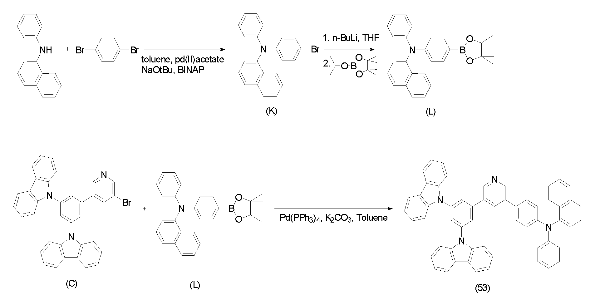
제1 단계; 중간체 생성물(K)의 합성First step; Synthesis of Intermediate Product (K)
3,6-디브로모벤젠 3.22g(13mmol), N-페닐-1-나프틸아민 3g(13mmol), 소디움-t-부톡사이드 1.24g(13mmol), 팔라듐아세테이트 30mg(0.13mmol), 및 바이냅(2,2'-bis(diphenylphosphino)-1,1'-binaphthyl, BINAP) 80mg(0.13mmol)를 톨루엔 200ml에 현탁하여, 질소 분위기하에서 24시간 가열 환류하였다.3,6-dibromobenzene 3.22 g (13 mmol), N-phenyl-1-naphthylamine 3 g (13 mmol), sodium-t-butoxide 1.24 g (13 mmol), palladium acetate 30 mg (0.13 mmol), and bi 80 mg (0.13 mmol) of synapses (2,2'-bis (diphenylphosphino) -1,1'-binaphthyl, BINAP) were suspended in 200 ml of toluene and heated to reflux for 24 hours in a nitrogen atmosphere.
상기 가열 환류한 반응용액을 2층으로 분리한 후, 유기층을 염화 나트륨 포화수용액으로 세정하고, 무수 황산나트륨으로 건조했다. 상기 건조한 반응용액에서 유기용매를 감압하에서 증류하여 제거한 후, 그 잔류물을 톨루엔으로 재결정하여, 석출한 결정을 여과에 의해 분리하고, 톨루엔으로 세정하여, 결정 상태의 중간체 생성물(K) 2.04g(42%)을 수득했다.After separating the heated and refluxed reaction solution into two layers, the organic layer was washed with saturated aqueous sodium chloride solution and dried over anhydrous sodium sulfate. After distilling off the organic solvent from the dried reaction solution under reduced pressure, the residue was recrystallized from toluene, the precipitated crystals were separated by filtration, washed with toluene, and 2.04 g of an intermediate product (K) in a crystalline state. 42%).
제2 단계; 중간체 생성물(L)의 합성Second step; Synthesis of Intermediate Product (L)
중간체 생성물(L) 3g(8mmol)을 테트라하이드로푸란 200ml에 현탁한 후, -76℃를 유지하며 질소 분위기하에서 1.6M 노르말 부틸리튬 5ml(8mmol)을 첨가하여 현탁액을 제조하였다. 30분 후 상기 현탁액에 이소프로필테트라메틸디옥사보로란 1.48g(8mmol)을 첨가하여 반응용액을 얻은 후, 실온까지 온도를 올렸다. Suspension was prepared by suspending 3 g (8 mmol) of the intermediate product (L) in 200 ml of tetrahydrofuran and then adding 5 ml (8 mmol) of 1.6 M normal butyllithium under nitrogen atmosphere at −76 ° C. After 30 minutes, 1.48 g (8 mmol) of isopropyltetramethyldioxaborolane was added to the suspension to obtain a reaction solution, and the temperature was raised to room temperature.
상기 반응용액을 2층으로 분리한 후, 유기층을 염화 나트륨 포화수용액으로 세정하고, 무수 황산나트륨으로 건조했다. 상기 건조한 반응용액에서 유기용매를 감압하에서 증류하여 제거한 후, 그 잔류물을 톨루엔으로 재결정하여, 석출한 결정을 여과에 의해 분리하고, 헥산으로 세정하여, 결정 상태의 중간체 생성물(L) 2.62g(78%)을 수득했다.After the reaction solution was separated into two layers, the organic layer was washed with saturated aqueous sodium chloride solution and dried over anhydrous sodium sulfate. After distilling off the organic solvent from the dried reaction solution under reduced pressure, the residue was recrystallized with toluene, and the precipitated crystals were separated by filtration, washed with hexane to give 2.62 g of an intermediate product (L) in a crystalline state. 78%) was obtained.
제4 단계; 화합물(53)의 합성A fourth step; Synthesis of Compound (53)
중간체 생성물(C) 3g(5.3mmol), 중간체 생성물(L) 2.23g(5.3mmol), 탄산칼륨 1.96g(14mmol), 및 테트라키스-(트리페닐포스핀)팔라듐 0.41g(0.3mmol)을 톨루엔 200ml, 및 정제수(50ml)에 현탁하여 24시간 동안 가열 교반하였다.3 g (5.3 mmol) of intermediate product (C), 2.23 g (5.3 mmol) of intermediate product (L), 1.96 g (14 mmol) of potassium carbonate, and 0.41 g (0.3 mmol) of tetrakis- (triphenylphosphine) palladium toluene It was suspended in 200 ml, and purified water (50 ml) and stirred with heating for 24 hours.
상기 가열 교반한 반응용액의 반응온도를 실온까지 냉각하고, 2층으로 분리한 후, 유기층의 용매를 감압 제거하여 수득한 잔유물을 실리카겔 컬럼 크로마토그래피로 정제하여 화합물(53) 2.68g(65%)을 수득했다.After the reaction temperature of the reaction mixture was cooled to room temperature, separated into two layers, the residue obtained by depressurizingly removing the solvent of the organic layer was purified by silica gel column chromatography to give 2.68 g (65%) of Compound (53). Obtained.
(( 실시예Example 2: 2: 유기광전소자의Organic photoelectric device 제작) making)
(( 실시예Example 2-1) 2-1)
상기 실시예 1-2에서 제조한 화합물(24)를 호스트로, Ir(PPy)3를 도펀트로 사용하여 다음과 같은 구조를 갖는 유기광전소자를 제작하였다,Using the compound (24) prepared in Example 1-2 as a host, Ir (PPy) 3 as a dopant to prepare an organic photoelectric device having the following structure,
양극으로는 ITO를 1000Å의 두께로 사용하였고, 음극으로는 알루미늄(Al)을 1000Å의 두께로 사용하였다.ITO was used as the cathode at a thickness of 1000 kPa, and aluminum (Al) was used as the cathode at a thickness of 1000 kPa.
구체적으로, 유기광전소자의 제조방법을 설명하면, 양극은 15Ψ/cm2 의 면저항값을 가진 ITO 유리 기판을 50mm×50mm×0.7mm크기로 잘라서 아세톤과 이소프로필 알콜과 순수물 속에서 각각 15분 동안 초음파 세정한 후, 30분 동안 UV 오존 세정하여 사용하였다.Specifically, the method of manufacturing the organic photoelectric device, the anode is cut into 50mm × 50mm × 0.7mm size ITO glass substrate having a sheet resistance value of 15Ψ / cm 2 and 15 minutes in acetone, isopropyl alcohol and pure water, respectively Ultrasonic cleaning for 3 minutes followed by UV ozone cleaning for 30 minutes.
상기 ITO 유리 기판 상부에 진공도 650×10-7Pa, 증착속도 0.1 내지 0.3nm/s의 조건으로 DNTPD(N,N'-di(4-(N,N'-diphenyl-amino)phenyl)-N,N'-diphenylbenzidine)와 NPD(N,N'-di-1-naphthyl-N,N'-diphenylbenzidine)를 증착하 여 막 두께 900Å의 정공수송층을 형성하였다.DNTPD (N, N'-di (4- (N, N'-diphenyl-amino) phenyl) -N under conditions of vacuum of 650 × 10 -7 Pa and deposition rate of 0.1 to 0.3 nm / s on the ITO glass substrate , N'-diphenylbenzidine) and NPD (N, N'-di-1-naphthyl-N, N'-diphenylbenzidine) were deposited to form a hole transport layer having a film thickness of 900Å.
이어서, 동일한 진공 증착 조건에서 상기 실시예 1-2에서 제조된 화합물(24)를 이용하여 막 두께 300Å의 발광층을 형성하였으며, 이때 인광 도판트인 Ir(PPy)3(여기에서 PPy는 2-페닐피리딘이다)을 동시 증착하였다.Subsequently, a light emitting layer having a film thickness of 300 μs was formed using the compound (24) prepared in Example 1-2 above under the same vacuum deposition conditions, wherein the phosphorescent dopant Ir (PPy) 3 (where PPy is 2-phenylpyridine). Co-deposited.
이때, 인광 도판트의 증착 속도를 조절하여, 발광층의 전체량을 100 중량%로 했을 때, 인광 도판트의 배합량이 10 중량%가 되도록 증착하였다.At this time, by adjusting the deposition rate of the phosphorescent dopant, when the total amount of the light emitting layer was 100% by weight, the deposition amount was deposited so that the compounding amount of the phosphorescent dopant was 10% by weight.
상기 발광층 상부에 동일한 진공 증착 조건을 이용하여 Balq(Bis(2-methyl-8-quinolinolate)-4-(phenylphenolate)aluminum)를 증착하여 막 두께 50Å의 정공저지층을 형성하였다. 이어서 동일한 진공 증착 조건에서 Alq3(tris(8-hydroxy-quinolate)aluminum)를 증착하여 막 두께 200Å의 전자수송층을 형성하였다. 상기 전자수송층 상부에 LiF와 Al을 순차적으로 증착하여 유기광전소자를 완성하였다.Balq (Bis (2-methyl-8-quinolinolate) -4- (phenylphenolate) aluminum) was deposited on the light emitting layer using the same vacuum deposition conditions to form a hole blocking layer having a thickness of 50 Å. Subsequently, Alq 3 (tris (8-hydroxy-quinolate) aluminum) was deposited under the same vacuum deposition conditions to form an electron transport layer having a thickness of 200 μs. LiF and Al were sequentially deposited on the electron transport layer to complete the organic photoelectric device.
유기광전소자는 5층 구조로 되어 있으며, 구체적으로 ITO/DNTPD(60nm)/NPD(30nm)/화합물(24)+Ir(PPy)3(10wt%, 30nm)/Balq(5nm)/Alq3(20nm)/LiF/Al(100nm)의 5층 구조로 제작하였다.The organic photoelectric device has a five-layer structure, and specifically, ITO / DNTPD (60nm) / NPD (30nm) / Compound (24) + Ir (PPy) 3 (10wt%, 30nm) / Balq (5nm) / Alq 3 ( 20 nm) / LiF / Al (100 nm) was produced.
(( 실시예Example 2-2) 2-2)
상기의 실시예 1-4에서 제조된 화합물(51)을 호스트로, Ir(Piq)2acac를 도펀트로 사용하여 다음과 같은 구조를 갖는 유기광전소자를 제작하였다,Using the compound (51) prepared in Example 1-4 as a host and Ir (Piq) 2 acac as a dopant, an organic photoelectric device having the following structure was prepared.
양극으로는 ITO를 1000Å의 두께로 사용하였고, 음극으로는 알루미늄(Al)을 1000Å의 두께로 사용하였다.ITO was used as the cathode at a thickness of 1000 kPa, and aluminum (Al) was used as the cathode at a thickness of 1000 kPa.
구체적으로, 유기광전소자의 제조방법을 설명하면, 양극은 15Ψ/cm2 의 면저항값을 가진 ITO 유리 기판을 50mm×50mm×0.7mm크기로 잘라서 아세톤과 이소프로필 알콜과 순수물 속에서 각 15분 동안 초음파 세정한 후, 30분 동안 UV 오존 세정하여 사용하였다.Specifically, the method of manufacturing the organic photoelectric device, the anode is cut into 50mm × 50mm × 0.7mm size ITO glass substrate having a sheet resistance value of 15Ψ / cm 2 each 15 minutes in acetone, isopropyl alcohol and pure water Ultrasonic cleaning for 3 minutes followed by UV ozone cleaning for 30 minutes.
상기 기판 상부에 진공도 650×10-7Pa, 증착속도 0.1 내지 0.3nm/s의 조건으로 DNTPD와 NPD를 증착하여 막 두께 900Å의 정공수송층을 형성하였다.DNTPD and NPD were deposited on the substrate at a vacuum degree of 650 × 10 −7 Pa and a deposition rate of 0.1 to 0.3 nm / s to form a hole transport layer having a film thickness of 900 Å.
이어서, 동일한 진공 증착 조건에서 화합물(51)을 이용하여 막 두께 300Å의 발광층을 형성하였으며, 이때 인광 도판트인 Ir(Piq)2acac을 동시 증착하였다.Subsequently, a light emitting layer having a film thickness of 300 Pa was formed using the compound 51 under the same vacuum deposition conditions, and Ir (Piq) 2 acac, which was a phosphorescent dopant, was simultaneously deposited.
이때, 인광 도판트의 증착 속도를 조절하여, 발광층의 전체량을 100 중량%로 했을 때, 인광 도판트의 배합량이 10 중량%가 되도록 증착하였다.At this time, by adjusting the deposition rate of the phosphorescent dopant, when the total amount of the light emitting layer was 100% by weight, the deposition amount was deposited so that the compounding amount of the phosphorescent dopant was 10% by weight.
상기 발광층 상부에 동일한 진공 증착 조건을 이용하여 BCP(2,9-Dimethyl-4,7-diphenyl-1,10-phenanthroline)를 증착하여 막 두께 50Å의 정공저지층을 형성하였다. 이어서 동일한 진공 증착 조건에서 Alq3를 증착하여 막 두께 200Å의 전자수송층을 형성하였다. 상기 전자수송층 상부에 LiF와 Al을 순차적으로 증착하여 유기광전소자를 완성하였다.BCP (2,9-Dimethyl-4,7-diphenyl-1,10-phenanthroline) was deposited on the light emitting layer using the same vacuum deposition conditions to form a hole blocking layer having a thickness of 50 Å. Subsequently, Alq 3 was deposited under the same vacuum deposition conditions to form an electron transport layer having a film thickness of 200 μs. LiF and Al were sequentially deposited on the electron transport layer to complete the organic photoelectric device.
유기광전소자는 5층 구조로 되어 있으며, 구체적으로 ITO/DNTPD(60nm)/NPD(30nm)/화합물(51)+Ir(Piq)2acac(10%[wt%], 30nm)/BCP(5nm)/Alq3(20nm)/LiF/Al(100nm)의 5층 구조로 제작하였다.The organic photoelectric device has a five-layer structure. Specifically, ITO / DNTPD (60 nm) / NPD (30 nm) / Compound (51) + Ir (Piq) 2 acac (10% [wt%], 30 nm) / BCP (5 nm) ) / Alq 3 (20 nm) / LiF / Al (100 nm).
(( 실시예Example 2-3) 2-3)
상기 실시예 1-5에서 제조된 화합물(53)을 호스트로 사용한 것을 제외하고는 실시예 2-2와 동일한 방법을 통하여 유기광전소자를 제조하였다. An organic photoelectric device was manufactured according to the same method as Example 2-2 except for using the compound (53) prepared in Example 1-5 as a host.
(( 비교예Comparative example 1) One)
상기 실시예 2-1에서 호스트로서 화합물(24) 대신 하기 화학식 8로 표시되는 4,4-N,N-다이카바졸바이페닐(CBP)를 이용한 것을 제외하고는 실시예 2-1과 동일하게 실시하여 ITO/DNTPD(60nm)/NPD(30nm)/CBP+Ir(PPy)3(10wt%, 30nm)/Balq(5nm)/Alq3(20nm)/LiF/Al(100nm)의 5층 구조를 갖는 유기광전소자를 제조하였다.As in Example 2-1, except that 4,4-N, N-dicarbazolebiphenyl (CBP) represented by the following Formula 8 was used instead of the compound (24) as the host in Example 2-1 ITO / DNTPD (60nm) / NPD (30nm) / CBP + Ir (PPy) 3 (10wt%, 30nm) / Balq (5nm) / Alq 3 (20nm) / LiF / Al (100nm) An organic photoelectric device having the same was prepared.
[화학식 8][Formula 8]
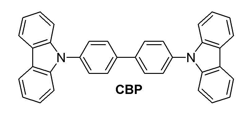
(( 비교예Comparative example 2) 2)
상기 실시예 2-2에서 호스트로서 화합물(51) 대신 상기 화학식 8로 표시되는 CBP를 이용한 것을 제외하고는 실시예 2-2와 동일한 방법으로, ITO/DNTPD(60nm)/NPD(30nm)/CBP+Ir(Piq)2acac(10wt%, 30nm)/BCP(5nm)/Alq3(20nm)/LiF/Al(100nm)의 5층 구조를 갖는 유기광전소자를 제조하였다.ITO / DNTPD (60nm) / NPD (30nm) / CBP in the same manner as in Example 2-2 except for using CBP represented by Formula 8 instead of Compound (51) as a host in Example 2-2. An organic photoelectric device having a five-layer structure of + Ir (Piq) 2 acac (10 wt%, 30 nm) / BCP (5 nm) / Alq 3 (20 nm) / LiF / Al (100 nm) was prepared.
(제조된 (Manufactured 유기광전소자용For organic photoelectric device 재료의 물성 측정) Measurement of material properties)
상기 실시예 1-2에서 제조된 유기광전소자용 재료에 대하여 Bruker 300MHz를 이용하여 1H-NMR을 측정하였고, 실시예 1-2에서 제조된 유기광전소자용 재료는 화합물(24)임을 확인하였다. 1 H-NMR was measured using Bruker 300MHz for the organic photoelectric device material prepared in Example 1-2, and it was confirmed that the organic photoelectric device material prepared in Example 1-2 was Compound (24). .
1H NMR (200MHz, CDCl3) δ 8.95(2H,d), 8.21(5H,m), 8.1(2H,d), 7.91(3H,t), 7.7(2H,m), 7.4(19H,m) ppm. 1 H NMR (200 MHz, CDCl 3 ) δ 8.95 (2H, d), 8.21 (5H, m), 8.1 (2H, d), 7.91 (3H, t), 7.7 (2H, m), 7.4 (19H, m ) ppm.
상기 실시예 1-2, 1-4, 및 1-5에서 제조된 유기광전소자용 재료의 유리전이온도(Tg)와 열분해온도(Td)를 DSC와 TGA로 측정하였다. 상기 실시예 1-2(실시예 2-1에 대응)에서 제조된 유기광전소자용 재료의 유리전이온도와 열분해온도를 하기 표 1에 나타내었고, 상기 실시예 1-4(실시예 2-2에 대응), 1-5(실시예 2-3에 대응)에서 제조된 유기광전소자용 재료의 유리전이온도와 열분해온도를 하기 표 2에 나타내었다.The glass transition temperature (Tg) and the thermal decomposition temperature (Td) of the organic photoelectric device material prepared in Examples 1-2, 1-4, and 1-5 were measured by DSC and TGA. The glass transition temperature and pyrolysis temperature of the organic photoelectric device material prepared in Example 1-2 (corresponding to Example 2-1) are shown in Table 1 below, and Example 1-4 (Example 2-2). The glass transition temperature and the thermal decomposition temperature of the organic photoelectric device material prepared in 1-5 (corresponding to Example 2-3) are shown in Table 2 below.
또한, 비교예 1, 및 2에서 호스트물질로 사용한 CBP의 유리전이온도와 열분 해온도도 DSC와 TGA로 측정하였고, 그 결과를 표 1, 및 표 2에 나타내었다.In addition, the glass transition temperature and thermal decomposition temperature of CBP used as the host material in Comparative Examples 1 and 2 were also measured by DSC and TGA, and the results are shown in Tables 1 and 2.
(( 유기광전소자의Organic photoelectric device 성능 측정) Performance measurement)
상기 실시예 2-1 내지 2-3, 비교예 1, 및 2에서 제조된 각각의 유기광전소자에 대하여 전압에 따른 발광 효율을 측정하였다. 구체적인 측정 방법은 다음과 같다.For each organic photoelectric device manufactured in Examples 2-1 to 2-3, Comparative Examples 1, and 2, light emission efficiency according to voltage was measured. The specific measuring method is as follows.
1) 전압 변화에 따른 전류 밀도의 변화 측정1) Measurement of change in current density according to voltage change
상기 실시예 2-1 내지 2-3, 비교예 1, 및 2에서 제조된 각각의 유기광전소자에 대해, 전압을 0V 부터 14V 까지 상승시키면서 전류-전압계(Keithley 2400)를 이용하여 단위소자에 흐르는 전류값을 측정하고, 측정된 전류값을 면적으로 나누어 전류 밀도를 측정하였다.For each of the organic photoelectric devices manufactured in Examples 2-1 to 2-3, Comparative Examples 1, and 2, the voltage flowed to the unit device using a current-voltmeter (Keithley 2400) while increasing the voltage from 0V to 14V. The current value was measured, and the current density was measured by dividing the measured current value by the area.
2) 전압 변화에 따른 휘도 변화 측정2) Measurement of luminance change according to voltage change
상기 실시예 2-1 내지 2-3, 비교예 1, 및 2에서 제조된 각각의 유기광전소자에 대해, 전압을 0V 부터 14V 까지 상승시키면서 휘도계(Minolta Cs-1000A)를 이용하여 휘도를 측정하였다.For each organic photoelectric device manufactured in Examples 2-1 to 2-3, Comparative Examples 1, and 2, luminance was measured using a luminance meter (Minolta Cs-1000A) while increasing the voltage from 0V to 14V. It was.
3) 발광 효율 측정3) Luminous efficiency measurement
상기 1) 과 2) 로부터 측정된 휘도 값과 전류 밀도, 및 전압을 이용하여 발광 효율을 계산하였고, 실시예 2-1, 및 비교예 1의 결과를 하기 표 1에 정리하였고, 실시예 2-2, 2-3, 및 비교예 2의 결과를 하기 표 2에 정리하였다.Luminous efficiency was calculated using the luminance values, current densities, and voltages measured from the above 1) and 2), and the results of Example 2-1 and Comparative Example 1 are summarized in Table 1 below, and Example 2- The results of 2, 2-3, and Comparative Example 2 are summarized in Table 2 below.
[표 1]TABLE 1
[표 2]TABLE 2
상기 표 1, 및 표 2를 참조하면, 본 발명의 일 구현예에 따른 바이폴라 유기화합물은 대부분의 경우 유리전이온도가 120℃ 이상이고, 열분해온도(Td)가 430℃ 이상의 값을 나타낸다. 따라서, 본 발명의 일 구현예에 따른 바이폴라 유기화합물을 비교예 1, 및 2에서 호스트 재료로 사용된 CBP(110oC)에 비해 매우 높은 열안정성을 갖음을 알 수 있다. Referring to Tables 1 and 2, the bipolar organic compound according to an embodiment of the present invention has a glass transition temperature of 120 ° C. or more and a thermal decomposition temperature (Td) of 430 ° C. or more in most cases. Therefore, it can be seen that the bipolar organic compound according to one embodiment of the present invention has a very high thermal stability compared to CBP (110 ° C.) used as the host material in Comparative Examples 1 and 2.
또한, 본 발명의 일 구현예에 따른 유기광전소자의 휘도 100nit에서 대부분의 구동전압은 6V 이하로 비교예 1, 및 2에 비하여 동등하거나 우수한 소자 성능을 나타내며, 실시예 2-1의 경우는 비교예 1에 비해 1.5V 이상 낮은 구동전압을 나타냄을 알 수 있다. 또한, 실시예 2-2의 경우, 비교예 2와 비교하여 1.5V 이상 낮은 구동전압을 나타내고, 실시예 2-3의 경우, 비교예 2에 비하여 0.5V 이상 낮은 구동전압을 나타내고 있음을 알 수 있다.In addition, most driving voltages of the organic photoelectric device according to the embodiment of the present invention at brightness of 100 nits are 6 V or less, which is equivalent to or superior to those of Comparative Examples 1 and 2, and compared with Example 2-1. It can be seen that the driving voltage is lower than 1.5V compared to Example 1. In addition, in Example 2-2, the driving voltage was lower than 1.5V compared to Comparative Example 2, and in Example 2-3, the driving voltage was lowered by 0.5V or higher than in Comparative Example 2. have.
또한 실시예 2-1의 경우, 비교예 1과 비교하여 향상된 소자 성능을 나타낸다. 상기 표 2에서 실시예 2-2의 경우 비교예 2와 동등한 수준의 발광효율을 나타내었고, 실시예 2-3의 경우, 비교예 2에 비해 전반적으로 높은 소자특성을 나타내 었다. In addition, in the case of Example 2-1, it shows an improved device performance compared to Comparative Example 1. In Table 2, Example 2-2 showed the same level of light emission efficiency as that of Comparative Example 2, and Example 2-3 showed overall higher device characteristics than Comparative Example 2.
따라서, 본 발명의 일 구현예에 따른 유기광전소자용 재료는 높은 열적 안정성을 가지며, 이를 이용하여 제조된 유기광전소자는 낮은 구동전압, 및 높은 발광효율을 나타내었으며, 비정질화의 증가와, 높은 Tg, Td로 인하여 열적 안정성이 증가됨으로써, 유기광전소자의 수명도 증가될 것으로 기대된다.Therefore, the organic photoelectric device material according to the embodiment of the present invention has high thermal stability, and the organic photoelectric device manufactured by using the same has a low driving voltage and high luminous efficiency, and increases in amorphousness and high As thermal stability increases due to Tg and Td, the lifespan of the organic photoelectric device is expected to increase.
이상 첨부된 도면, 및 표를 참조하여 본 발명의 일 구현예를 설명하였으나, 본 발명은 상기 실시예에 한정되는 것이 아니라 서로 다른 다양한 형태로 제조될 수 있으며, 본 발명이 속하는 기술 분야에서 통상의 지식을 가진 자는 본 발명의 기술적 사상이나 필수적인 특징을 변경하지 않고서 다른 구체적인 형태로 실시될 수 있다는 것을 이해할 수 있을 것이다. 그러므로 이상에서 기술한 실시예는 모든 면에서 예시적인 것이며 한정적이 아닌 것으로 이해해야만 한다.Although one embodiment of the present invention has been described above with reference to the accompanying drawings, and the table, the present invention is not limited to the above embodiment, but may be manufactured in various forms, which are common in the art to which the present invention pertains. Those skilled in the art can understand that the present invention can be implemented in other specific forms without changing the technical spirit or essential features of the present invention. Therefore, it should be understood that the embodiments described above are exemplary in all respects and not restrictive.
도 1 내지 도 5는 본 발명의 일 구현예에 따른 유기광전소자용 재료를 이용하여 제조될 수 있는 유기광전소자에 대한 다양한 구현예들을 나타내는 단면도.1 to 5 are cross-sectional views showing various embodiments of the organic photoelectric device that can be manufactured using the material for an organic photoelectric device according to an embodiment of the present invention.
<도면의 주요 부분에 대한 부호의 설명><Explanation of symbols for the main parts of the drawings>
100 : 유기광전소자 110 : 음극100: organic photoelectric device 110: cathode
120 : 양극 105 : 유기 박막층 120: anode 105: organic thin film layer
130 : 발광층 140 : 정공수송층130: light emitting layer 140: hole transport layer
150 : 전자수송층 160 : 전자주입층150: electron transport layer 160: electron injection layer
170 : 정공주입층170: hole injection layer
Claims (12)


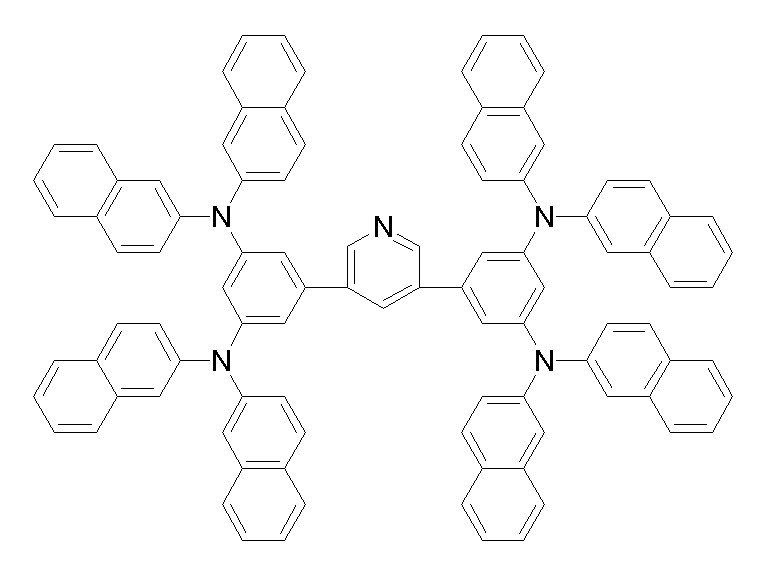
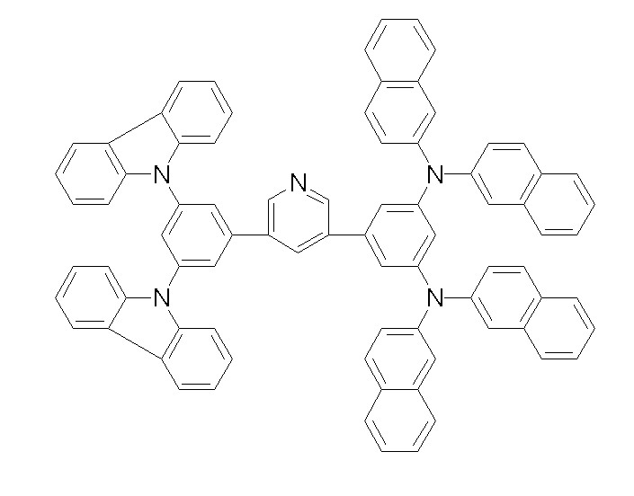

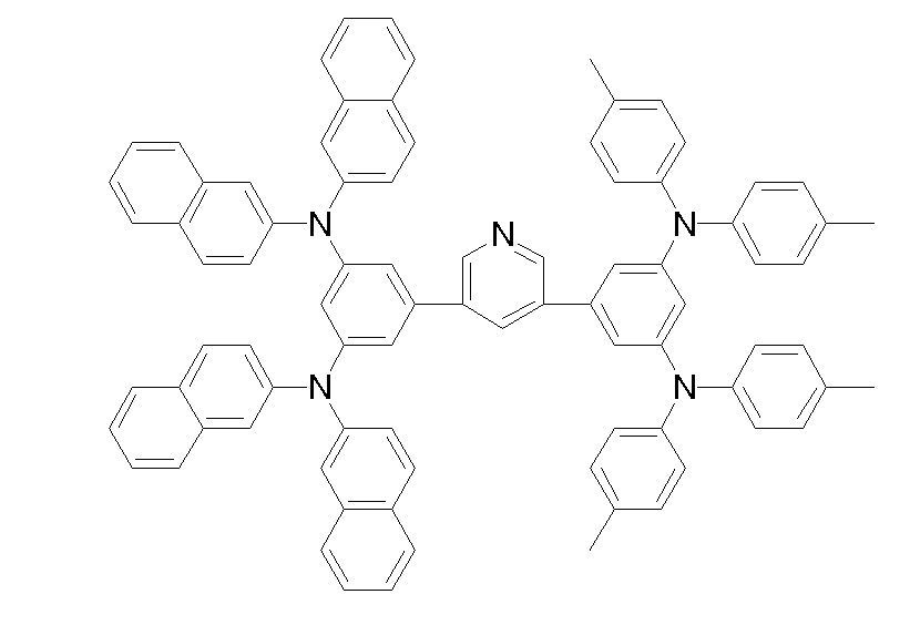


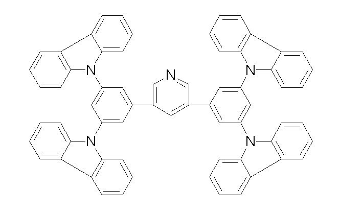
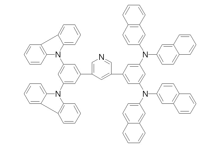

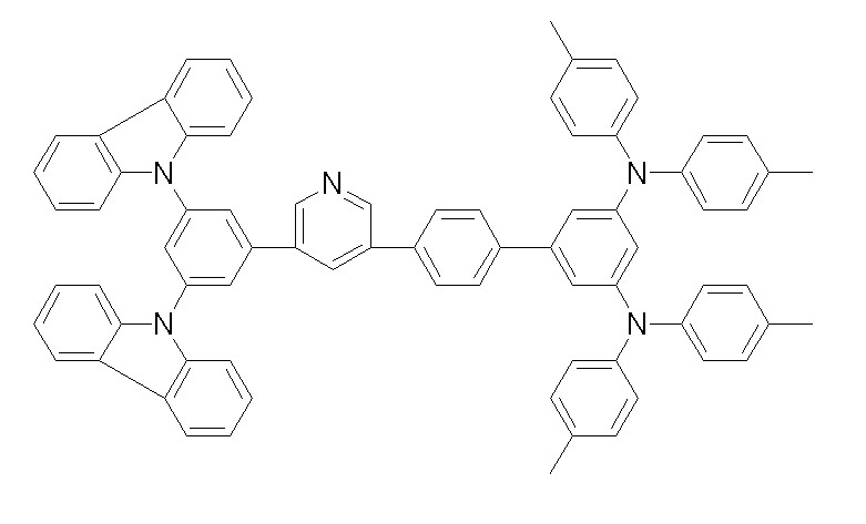
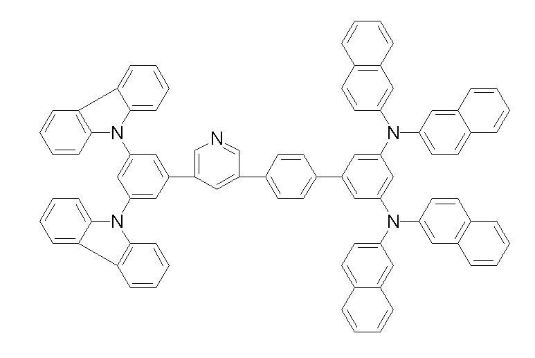


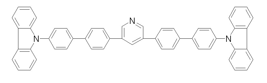


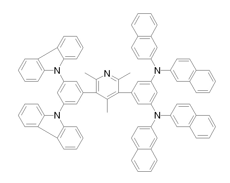
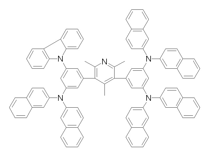


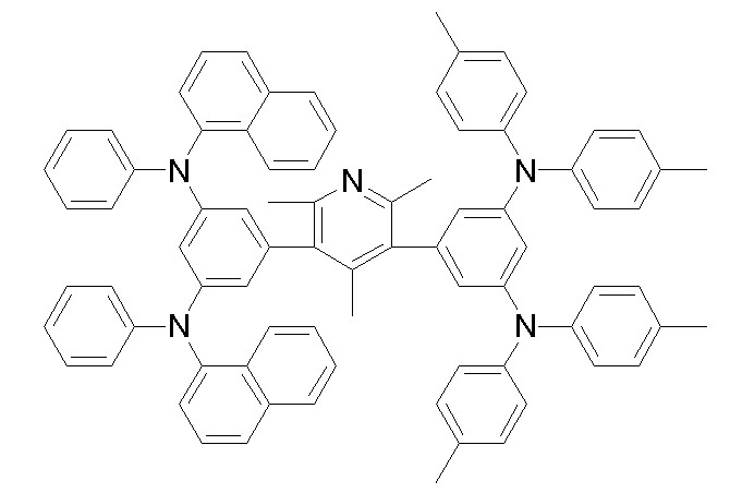


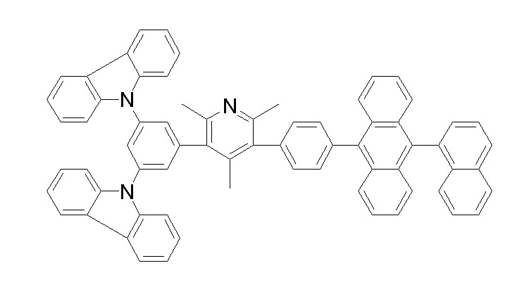


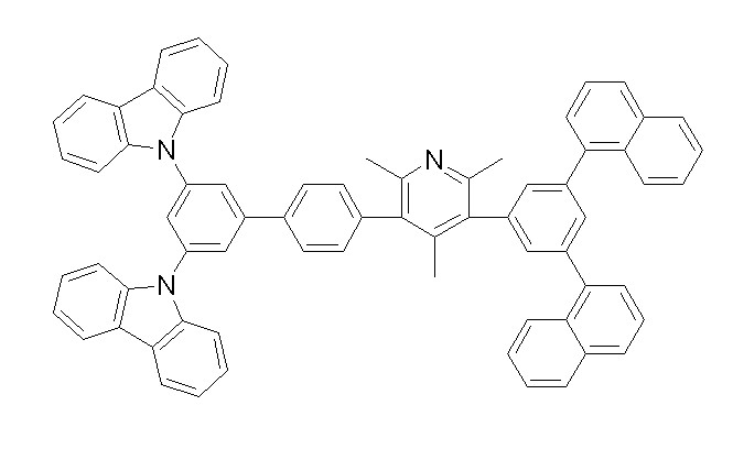
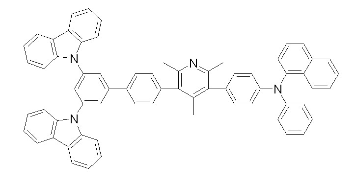


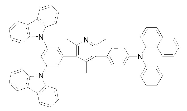


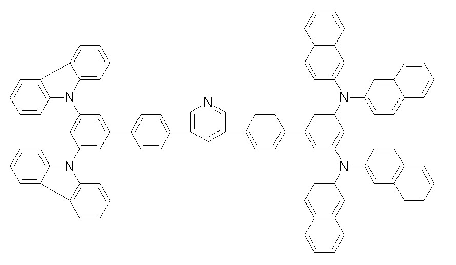

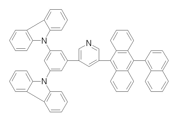
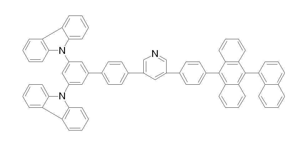
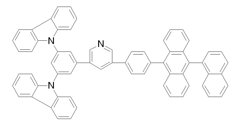
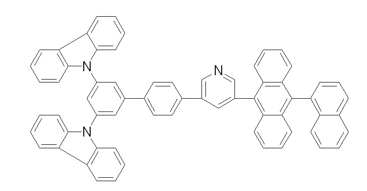


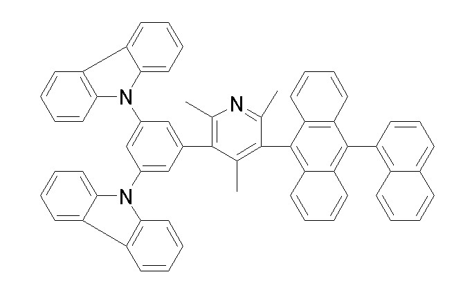


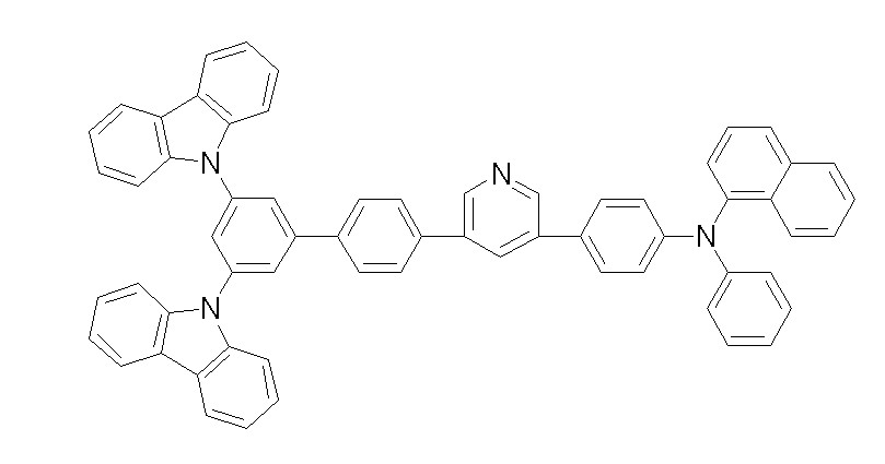
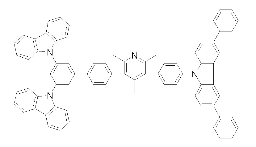
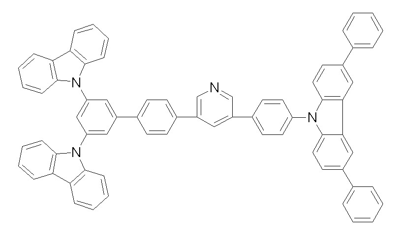

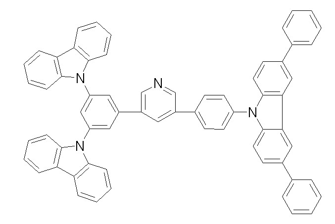

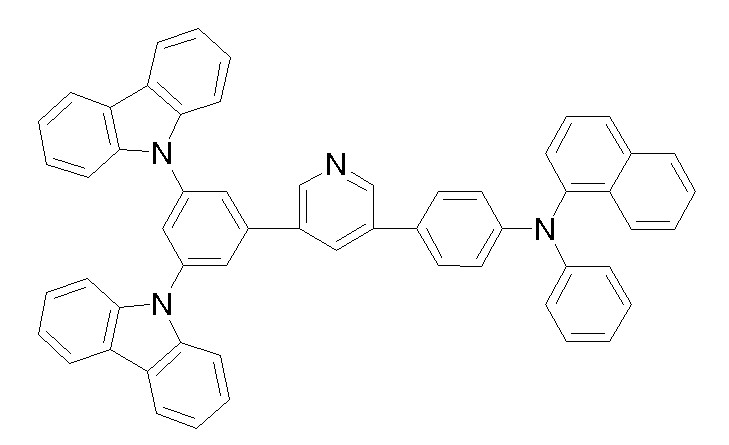
Priority Applications (5)
| Application Number | Priority Date | Filing Date | Title |
|---|---|---|---|
| KR1020070110984A KR100957620B1 (en) | 2007-11-01 | 2007-11-01 | Material for organic photoelectric device, and organic photoelectric device using same |
| PCT/KR2008/006452 WO2009057978A2 (en) | 2007-11-01 | 2008-10-31 | Material for organic photoelectric device, and organic photoelectric device thereby |
| CN2008801085156A CN101809117B (en) | 2007-11-01 | 2008-10-31 | Material for organic photoelectric device and organic photoelectric device |
| US12/662,765 US8120243B2 (en) | 2007-11-01 | 2010-05-03 | Material for organic photoelectric device, and organic photoelectric device thereby |
| US13/242,976 US20120012830A1 (en) | 2007-11-01 | 2011-09-23 | Material for organic photoelectric device, and organic photoelectric device thereby |
Applications Claiming Priority (1)
| Application Number | Priority Date | Filing Date | Title |
|---|---|---|---|
| KR1020070110984A KR100957620B1 (en) | 2007-11-01 | 2007-11-01 | Material for organic photoelectric device, and organic photoelectric device using same |
Publications (2)
| Publication Number | Publication Date |
|---|---|
| KR20090044752A KR20090044752A (en) | 2009-05-07 |
| KR100957620B1 true KR100957620B1 (en) | 2010-05-13 |
Family
ID=40591671
Family Applications (1)
| Application Number | Title | Priority Date | Filing Date |
|---|---|---|---|
| KR1020070110984A Active KR100957620B1 (en) | 2007-11-01 | 2007-11-01 | Material for organic photoelectric device, and organic photoelectric device using same |
Country Status (4)
| Country | Link |
|---|---|
| US (2) | US8120243B2 (en) |
| KR (1) | KR100957620B1 (en) |
| CN (1) | CN101809117B (en) |
| WO (1) | WO2009057978A2 (en) |
Families Citing this family (17)
| Publication number | Priority date | Publication date | Assignee | Title |
|---|---|---|---|---|
| CN101657517B (en) * | 2007-04-13 | 2013-03-27 | 第一毛织株式会社 | Material for organic photoelectric device including electron transporting unit and hole transporting unit, and organic photoelectric device including the same |
| KR101233380B1 (en) | 2009-10-21 | 2013-02-15 | 제일모직주식회사 | Novel compound for organic photoelectric device and organic photoelectric device including the same |
| US8785003B2 (en) | 2010-03-05 | 2014-07-22 | Idemtisu Kosan Co., Ltd. | Material for organic electroluminescence device and organic electroluminescence device using the same |
| KR101319734B1 (en) * | 2010-05-20 | 2013-10-17 | 주식회사 두산 | Novel hybrid organic compounds and organic electroluminescence device comprising the same |
| KR101531612B1 (en) * | 2010-12-02 | 2015-06-25 | 제일모직 주식회사 | Compound for organic photoelectric device and organic photoelectric device including the same |
| KR101497134B1 (en) * | 2011-12-29 | 2015-03-02 | 제일모직 주식회사 | Compound for organic optoelectronic device, organic light emitting diode including the same and display including the organic light emitting diode |
| KR101507001B1 (en) * | 2011-12-30 | 2015-03-31 | 제일모직 주식회사 | Compound for organic optoelectronic device, organic light emitting diode including the same and display including the organic light emitting diode |
| CN103965440B (en) * | 2013-01-31 | 2016-08-24 | 顾玉奎 | an organic semiconductor material |
| CN105646852B (en) * | 2013-01-31 | 2017-11-24 | 南安市鑫灿品牌运营有限公司 | A kind of preparation method of organic semiconducting materials |
| CN103664495B (en) * | 2013-12-10 | 2016-07-06 | 京东方科技集团股份有限公司 | Anthracene derivative and preparation method, application and organic luminescent device |
| CN104151296A (en) * | 2014-06-27 | 2014-11-19 | 南京工业大学 | Synthesis method and application of pyridine derivatives |
| JP6764671B2 (en) * | 2015-04-14 | 2020-10-07 | 株式会社半導体エネルギー研究所 | Heterocyclic compounds, light emitting devices, light emitting devices, electronic devices, and lighting devices |
| EP3609978B1 (en) | 2017-04-13 | 2021-03-17 | cynora GmbH | Organic molecules in particular for use in optoelectronic devices |
| CN109980085B (en) * | 2017-12-28 | 2021-08-31 | 中节能万润股份有限公司 | An organic electroluminescent device containing a cover layer and its use |
| SMT202200134T1 (en) | 2018-03-08 | 2022-05-12 | Incyte Corp | Aminopyrazine diol compounds as pi3k-y inhibitors |
| EP3575377B1 (en) * | 2018-05-31 | 2021-03-17 | Cynora Gmbh | Organic molecules for optoelectronic devices |
| US11046658B2 (en) | 2018-07-02 | 2021-06-29 | Incyte Corporation | Aminopyrazine derivatives as PI3K-γ inhibitors |
Citations (2)
| Publication number | Priority date | Publication date | Assignee | Title |
|---|---|---|---|---|
| EP0926216A1 (en) * | 1997-12-01 | 1999-06-30 | Chisso Corporation | Organic electroluminescent device using a triarylamine derivative |
| JP2007169268A (en) * | 2005-11-22 | 2007-07-05 | Mitsubishi Chemicals Corp | Organic compound, charge transport material, charge transport material composition, and organic electroluminescent device |
Family Cites Families (11)
| Publication number | Priority date | Publication date | Assignee | Title |
|---|---|---|---|---|
| US4769292A (en) * | 1987-03-02 | 1988-09-06 | Eastman Kodak Company | Electroluminescent device with modified thin film luminescent zone |
| JP3170957B2 (en) * | 1993-06-28 | 2001-05-28 | 富士電機株式会社 | Organic thin film light emitting device |
| JP4320811B2 (en) | 1998-12-07 | 2009-08-26 | コニカミノルタホールディングス株式会社 | Organic electroluminescence device |
| JP2001131150A (en) | 1999-10-29 | 2001-05-15 | Toyota Central Res & Dev Lab Inc | Organic electroluminescent device and vinylpyridine derivative compound |
| EP1489155A4 (en) * | 2002-03-22 | 2006-02-01 | Idemitsu Kosan Co | MATERIAL FOR ORGANIC ELECTROLUMINESCENT DEVICES AND ORGANIC ELECTROLUMINESCENT DEVICES PRODUCED WITH THIS MATERIAL |
| JP4223768B2 (en) | 2002-08-30 | 2009-02-12 | 富士フイルム株式会社 | Light emitting element |
| EP2592905B1 (en) * | 2003-07-31 | 2014-11-12 | Mitsubishi Chemical Corporation | Compound, charge transporting material and organic electroluminescent element |
| EP1724323A4 (en) * | 2004-03-08 | 2008-11-05 | Idemitsu Kosan Co | MATERIAL FOR ORGANIC ELECTROLUMINESCENCE DEVICE AND ORGANIC ELECTROLUMINESCENCE DEVICE USING SUCH MATERIAL |
| US20080067922A1 (en) * | 2004-09-22 | 2008-03-20 | Ayataka Endo | Organic Electroluminescent Device |
| KR20120082938A (en) * | 2004-12-24 | 2012-07-24 | 미쓰비시 가가꾸 가부시키가이샤 | Organic compound, charge-transporting material, and organic electroluminescent element |
| JP4372733B2 (en) * | 2005-07-02 | 2009-11-25 | 株式会社ナナオ | Liquid crystal display |
-
2007
- 2007-11-01 KR KR1020070110984A patent/KR100957620B1/en active Active
-
2008
- 2008-10-31 CN CN2008801085156A patent/CN101809117B/en active Active
- 2008-10-31 WO PCT/KR2008/006452 patent/WO2009057978A2/en not_active Ceased
-
2010
- 2010-05-03 US US12/662,765 patent/US8120243B2/en active Active
-
2011
- 2011-09-23 US US13/242,976 patent/US20120012830A1/en not_active Abandoned
Patent Citations (2)
| Publication number | Priority date | Publication date | Assignee | Title |
|---|---|---|---|---|
| EP0926216A1 (en) * | 1997-12-01 | 1999-06-30 | Chisso Corporation | Organic electroluminescent device using a triarylamine derivative |
| JP2007169268A (en) * | 2005-11-22 | 2007-07-05 | Mitsubishi Chemicals Corp | Organic compound, charge transport material, charge transport material composition, and organic electroluminescent device |
Also Published As
| Publication number | Publication date |
|---|---|
| US20100213826A1 (en) | 2010-08-26 |
| WO2009057978A3 (en) | 2009-06-04 |
| KR20090044752A (en) | 2009-05-07 |
| CN101809117A (en) | 2010-08-18 |
| CN101809117B (en) | 2013-06-19 |
| US8120243B2 (en) | 2012-02-21 |
| WO2009057978A2 (en) | 2009-05-07 |
| US20120012830A1 (en) | 2012-01-19 |
Similar Documents
| Publication | Publication Date | Title |
|---|---|---|
| KR100957620B1 (en) | Material for organic photoelectric device, and organic photoelectric device using same | |
| KR101030021B1 (en) | Organic photoelectric device material including bipolar organic compound having both hole transporter and electron transporter in a molecule and organic photoelectric device using same | |
| KR101247626B1 (en) | Compounds for organic photoelectric device and organic photoelectric device containing the same | |
| KR100994083B1 (en) | Compound, charge transport material and organic electroluminescent device | |
| KR101212670B1 (en) | Composition for organic photoelectric device, organic photoelectric device using the same and display device comprising the same | |
| KR101084287B1 (en) | Material for organic photoelectric device comprising fluorene derivative compound and organic photoelectric device comprising same | |
| KR101174090B1 (en) | Material for organic photoelectric device and organic photoelectric device including the same | |
| KR101288557B1 (en) | Novel compound for organic photoelectric device and organic photoelectric device including the same | |
| TWI518071B (en) | Organic light field components | |
| KR20090024998A (en) | Organic photoelectric device material including bipolar organic compound having hole transporter and electron transporter in a molecule and organic photoelectric device using the same | |
| CN101952389B (en) | Luminescent element material and luminescent element | |
| KR101233369B1 (en) | Novel compound for organic photoelectric device and organic photoelectric device including the same | |
| KR20110048840A (en) | Compound for organic photoelectric device and organic photoelectric device comprising same | |
| CN101107244B (en) | Organic compounds, charge transport materials and organic electroluminescence elements | |
| KR101233367B1 (en) | Novel compound for organic photoelectric device and organic photoelectric device including the same | |
| JP2005268199A (en) | Compound, charge transport material and organic electroluminescence device | |
| CN102459507A (en) | Compound for an organic photoelectric element, and an organic photoelectric element comprising the same | |
| KR20100075079A (en) | Novel compound for organic photoelectric device and organic photoelectric device including the same | |
| KR101233375B1 (en) | Novel compound for organic photoelectric device and organic photoelectric device including the same | |
| CN101638380A (en) | Compound, charge transport material, and organic electroluminescent element | |
| KR100951707B1 (en) | Organic photoelectric device material including cyclohexane and organic photoelectric device comprising the same | |
| JP2004131464A (en) | Organometallic complex, luminescent dye, organic electroluminescent device material, and organic electroluminescent device |
Legal Events
| Date | Code | Title | Description |
|---|---|---|---|
| A201 | Request for examination | ||
| PA0109 | Patent application |
Patent event code: PA01091R01D Comment text: Patent Application Patent event date: 20071101 |
|
| PA0201 | Request for examination | ||
| E902 | Notification of reason for refusal | ||
| PE0902 | Notice of grounds for rejection |
Comment text: Notification of reason for refusal Patent event date: 20090326 Patent event code: PE09021S01D |
|
| PG1501 | Laying open of application | ||
| E90F | Notification of reason for final refusal | ||
| PE0902 | Notice of grounds for rejection |
Comment text: Final Notice of Reason for Refusal Patent event date: 20091116 Patent event code: PE09021S02D |
|
| E701 | Decision to grant or registration of patent right | ||
| PE0701 | Decision of registration |
Patent event code: PE07011S01D Comment text: Decision to Grant Registration Patent event date: 20100430 |
|
| GRNT | Written decision to grant | ||
| PR0701 | Registration of establishment |
Comment text: Registration of Establishment Patent event date: 20100504 Patent event code: PR07011E01D |
|
| PR1002 | Payment of registration fee |
Payment date: 20100504 End annual number: 3 Start annual number: 1 |
|
| PG1601 | Publication of registration | ||
| FPAY | Annual fee payment |
Payment date: 20130313 Year of fee payment: 4 |
|
| PR1001 | Payment of annual fee |
Payment date: 20130313 Start annual number: 4 End annual number: 4 |
|
| FPAY | Annual fee payment |
Payment date: 20140401 Year of fee payment: 5 |
|
| PR1001 | Payment of annual fee |
Payment date: 20140401 Start annual number: 5 End annual number: 5 |
|
| FPAY | Annual fee payment |
Payment date: 20160426 Year of fee payment: 7 |
|
| PR1001 | Payment of annual fee |
Payment date: 20160426 Start annual number: 7 End annual number: 7 |
|
| FPAY | Annual fee payment |
Payment date: 20170424 Year of fee payment: 8 |
|
| PR1001 | Payment of annual fee |
Payment date: 20170424 Start annual number: 8 End annual number: 8 |
|
| FPAY | Annual fee payment |
Payment date: 20180503 Year of fee payment: 9 |
|
| PR1001 | Payment of annual fee |
Payment date: 20180503 Start annual number: 9 End annual number: 9 |
|
| FPAY | Annual fee payment |
Payment date: 20190502 Year of fee payment: 10 |
|
| PR1001 | Payment of annual fee |
Payment date: 20190502 Start annual number: 10 End annual number: 10 |
|
| PR1001 | Payment of annual fee |
Payment date: 20200506 Start annual number: 11 End annual number: 11 |
|
| PR1001 | Payment of annual fee |
Payment date: 20210429 Start annual number: 12 End annual number: 12 |
|
| PR1001 | Payment of annual fee |
Payment date: 20220502 Start annual number: 13 End annual number: 13 |
|
| PR1001 | Payment of annual fee |
Payment date: 20230425 Start annual number: 14 End annual number: 14 |
|
| PR1001 | Payment of annual fee |
Payment date: 20240424 Start annual number: 15 End annual number: 15 |
|
| PR1001 | Payment of annual fee |
Payment date: 20250429 Start annual number: 16 End annual number: 16 |