KR100955766B1 - Data transmission method sharing frequency band with existing communication system - Google Patents
Data transmission method sharing frequency band with existing communication system Download PDFInfo
- Publication number
- KR100955766B1 KR100955766B1 KR1020080044864A KR20080044864A KR100955766B1 KR 100955766 B1 KR100955766 B1 KR 100955766B1 KR 1020080044864 A KR1020080044864 A KR 1020080044864A KR 20080044864 A KR20080044864 A KR 20080044864A KR 100955766 B1 KR100955766 B1 KR 100955766B1
- Authority
- KR
- South Korea
- Prior art keywords
- communication system
- existing communication
- impulse response
- max
- receiver
- Prior art date
- Legal status (The legal status is an assumption and is not a legal conclusion. Google has not performed a legal analysis and makes no representation as to the accuracy of the status listed.)
- Expired - Fee Related
Links
Images


Classifications
-
- H—ELECTRICITY
- H04—ELECTRIC COMMUNICATION TECHNIQUE
- H04L—TRANSMISSION OF DIGITAL INFORMATION, e.g. TELEGRAPHIC COMMUNICATION
- H04L27/00—Modulated-carrier systems
- H04L27/0006—Assessment of spectral gaps suitable for allocating digitally modulated signals, e.g. for carrier allocation in cognitive radio
-
- H—ELECTRICITY
- H04—ELECTRIC COMMUNICATION TECHNIQUE
- H04L—TRANSMISSION OF DIGITAL INFORMATION, e.g. TELEGRAPHIC COMMUNICATION
- H04L27/00—Modulated-carrier systems
- H04L27/10—Frequency-modulated carrier systems, i.e. using frequency-shift keying
- H04L27/12—Modulator circuits; Transmitter circuits
-
- H—ELECTRICITY
- H04—ELECTRIC COMMUNICATION TECHNIQUE
- H04L—TRANSMISSION OF DIGITAL INFORMATION, e.g. TELEGRAPHIC COMMUNICATION
- H04L5/00—Arrangements affording multiple use of the transmission path
- H04L5/0001—Arrangements for dividing the transmission path
- H04L5/0028—Variable division
-
- H—ELECTRICITY
- H04—ELECTRIC COMMUNICATION TECHNIQUE
- H04W—WIRELESS COMMUNICATION NETWORKS
- H04W16/00—Network planning, e.g. coverage or traffic planning tools; Network deployment, e.g. resource partitioning or cells structures
- H04W16/14—Spectrum sharing arrangements between different networks
-
- H—ELECTRICITY
- H04—ELECTRIC COMMUNICATION TECHNIQUE
- H04L—TRANSMISSION OF DIGITAL INFORMATION, e.g. TELEGRAPHIC COMMUNICATION
- H04L5/00—Arrangements affording multiple use of the transmission path
- H04L5/003—Arrangements for allocating sub-channels of the transmission path
- H04L5/0058—Allocation criteria
-
- Y—GENERAL TAGGING OF NEW TECHNOLOGICAL DEVELOPMENTS; GENERAL TAGGING OF CROSS-SECTIONAL TECHNOLOGIES SPANNING OVER SEVERAL SECTIONS OF THE IPC; TECHNICAL SUBJECTS COVERED BY FORMER USPC CROSS-REFERENCE ART COLLECTIONS [XRACs] AND DIGESTS
- Y02—TECHNOLOGIES OR APPLICATIONS FOR MITIGATION OR ADAPTATION AGAINST CLIMATE CHANGE
- Y02D—CLIMATE CHANGE MITIGATION TECHNOLOGIES IN INFORMATION AND COMMUNICATION TECHNOLOGIES [ICT], I.E. INFORMATION AND COMMUNICATION TECHNOLOGIES AIMING AT THE REDUCTION OF THEIR OWN ENERGY USE
- Y02D30/00—Reducing energy consumption in communication networks
- Y02D30/70—Reducing energy consumption in communication networks in wireless communication networks
Landscapes
- Engineering & Computer Science (AREA)
- Signal Processing (AREA)
- Computer Networks & Wireless Communication (AREA)
- Physics & Mathematics (AREA)
- Health & Medical Sciences (AREA)
- General Health & Medical Sciences (AREA)
- Spectroscopy & Molecular Physics (AREA)
- Mobile Radio Communication Systems (AREA)
Abstract
기존 통신시스템과 주파수 대역을 공유하는 데이터 전송 방법은 기존 통신시스템의 수신기의 임펄스 응답, 채널의 임펄스 응답 및 기존 통신시스템으로부터의 간섭 신호의 전력 스펙트럼을 이용하여 송신 파형을 구하는 단계 및 상기 송신 파형을 이용하여 데이터를 전송하는 단계를 포함한다. 기존 통신시스템에 대하여 간섭을 일으키지 않으면서 공유 통신시스템의 데이터 전송 성능을 최대화할 수 있다.A data transmission method sharing a frequency band with an existing communication system includes obtaining a transmission waveform using an impulse response of a receiver of an existing communication system, an impulse response of a channel, and a power spectrum of an interference signal from the existing communication system, and using the transmission waveform. And transmitting the data. It is possible to maximize the data transmission performance of the shared communication system without causing interference to the existing communication system.
Description
본 발명은 데이터 전송 방법에 관한 것으로, 보다 상세하게는 기존 통신시스템과 주파수 대역을 공유하는 데이터 전송 방법에 관한 것이다.The present invention relates to a data transmission method, and more particularly, to a data transmission method for sharing a frequency band with an existing communication system.
주파수 자원은 한정되어 있으므로, 이를 효율적으로 활용하여야 한다. 주파수 자원을 효율적으로 활용하기 위한 다양한 방법 중에서 복수의 통신 시스템이 동일한 주파수 대역을 공유하는 방법이 있다. 즉, 기존 통신시스템이 이미 사용하고 있는 주파수 대역을 이용하여 데이터를 전송하는 방법에 관한 다양한 기술이 제안되어 왔다.Because frequency resources are limited, they should be used efficiently. Among various methods for efficiently utilizing frequency resources, a plurality of communication systems share the same frequency band. That is, various techniques for transmitting data using a frequency band already used by the existing communication system have been proposed.
J.H.Cho의 "Joint transmitter and receiver optimization in additive cyclostationary noise", IEEE Transactions on Information Theory 2004년 12월, pp.3396-3405에 의하면 기존 통신시스템과 주파수 대역을 공유하는 통신시스템의 수신기 출력의 평균제곱오차(Mean-Squared Error(이하, MSE라 한다))를 최소화하는 방법이 개시되어 있다. 또한, H.S.Mir와 S.Roy의 "Optimum transmitter/receiver design for a narrowband overlay in noncoordinated subscriber lines", IEEE Transactions on Communications, 2004년 6월, pp.992-998에 의하면 기존 통신시스템의 수신기 출력의 추가적인 평균제곱오차(excess MSE)를 어느 정도 허용하면서 기존 통신시스템과 주파수 대역을 공유하는 통신시스템의 수신기 출력의 평균제곱오차를 최소화하는 방법이 개시되어 있다.JHCho's "Joint transmitter and receiver optimization in additive cyclostationary noise", IEEE Transactions on Information Theory December 2004, pp.3396-3405 According to the present invention, a method of minimizing a mean square error (hereinafter, referred to as MSE) of a receiver output of a communication system sharing a frequency band with an existing communication system is disclosed. Also, according to HSMir and S.Roy's "Optimum transmitter / receiver design for a narrowband overlay in noncoordinated subscriber lines", IEEE Transactions on Communications, June 2004, pp.992-998 A method of minimizing the mean square error of a receiver output of a communication system sharing a frequency band with the existing communication system while allowing a certain additional MSE of the receiver output of the existing communication system is disclosed.
그런데, 종래 기술에 따르면 기존 통신시스템과 주파수 대역을 공유하는 통신시스템이 신호를 송출하는 경우, 그 신호는 기존 통신시스템에 대하여 간섭을 일으켜 기존 통신시스템의 성능을 현저히 떨어뜨린다. However, according to the related art, when a communication system sharing a frequency band with an existing communication system transmits a signal, the signal interferes with the existing communication system, thereby significantly reducing the performance of the existing communication system.
또한, 종래 기술에 따르면 기존 통신시스템과 주파수 대역을 공유하는 통신시스템에 대한 기존 통신시스템의 간섭 영향이 여전히 남아 있어, 그 성능 면에서 개선이 요구된다.In addition, according to the prior art, the interference effect of the existing communication system on the communication system sharing the frequency band with the existing communication system still remains, and the improvement in performance is required.
따라서, 기존 통신시스템과 주파수 대역을 공유하는 통신시스템이 데이터를 전송하는데 있어서, 기존 통신시스템에 대한 간섭 영향을 줄이는 것과 동시에, 상기 기존 통신시스템과 주파수 대역을 공유하는 통신시스템의 데이터 전송 효율을 향상시키기 위한 다양한 시도가 있다.Accordingly, when a communication system sharing a frequency band with an existing communication system transmits data, the interference effect on the existing communication system is reduced, and the data transmission efficiency of the communication system sharing a frequency band with the existing communication system is improved. There are various attempts to make it work.
본 발명의 기술적 과제는 기존 통신시스템과 주파수 대역을 공유하는 통신시스템의 데이터 전송 효율을 향상시키는 것이다.An object of the present invention is to improve data transmission efficiency of a communication system sharing a frequency band with an existing communication system.
본 발명의 다른 기술적 과제는 기존 통신시스템과 주파수 대역을 공유하는 통신시스템이 데이터를 전송함에 있어서 기존 통신시스템에 대하여 간섭을 일으키지 않는 것이다.Another technical problem of the present invention is that a communication system sharing a frequency band with an existing communication system does not cause interference with an existing communication system in transmitting data.
본 발명의 일 양태에 따른 기존 통신시스템과 주파수 대역을 공유하는 데이터 전송 방법은 기존 통신시스템의 수신기의 임펄스 응답, 채널의 임펄스 응답 및 기존 통신시스템으로부터의 간섭 신호의 전력 스펙트럼을 이용하여 송신 파형을 구하는 단계 및 상기 송신 파형을 이용하여 데이터를 전송하는 단계를 포함한다.According to an aspect of the present invention, a data transmission method sharing a frequency band with an existing communication system includes a transmission waveform using an impulse response of a receiver of an existing communication system, an impulse response of a channel, and a power spectrum of an interference signal from the existing communication system. Obtaining and transmitting data using the transmission waveform.
본 발명의 다른 양태에 따른 기존 통신시스템과 주파수 대역을 공유하는 데이터 수신 방법은 송신 파형을 통하여 송신되는 수신 신호를 수신하는 단계 및 상기 수신 신호를 처리하는 단계를 포함하되, 상기 송신 파형은 기존 통신시스템의 수신기의 임펄스 응답과 채널의 임펄스 응답을 이용하여 행렬 G(f)를 구하고, 기존 통신시스템에서 공유 통신시스템으로의 간섭 신호의 전력 스펙트럼과 공유 통신시스템 채널의 임펄스 응답을 이용하여 행렬 C(f)를 구하여, 상기 행렬 G(f)와 C(f)로부터 얻어지는 임시 행렬의 최대 고유값 λmax(f)를 구하며, 상기 최대 고유값 λmax(f)으로부터 얻어지는 최적의 에너지 할당값 aopt(f)와 상기 최대 고유값 λmax(f)의 고유 벡터 v max(f)를 이용하여 구하고, 상기 수신 신호는 사이클릭 위너 필터(Cyclic Wiener Filter)인 LMMSE 수신기를 이용하여 처리한다.A data receiving method for sharing a frequency band with an existing communication system according to another aspect of the present invention includes receiving a received signal transmitted through a transmission waveform and processing the received signal, wherein the transmission waveform is an existing communication The matrix G (f) is obtained using the impulse response of the receiver of the system and the impulse response of the channel, and the matrix C (using the power spectrum of the interference signal from the existing communication system to the shared communication system and the impulse response of the shared communication system channel). f) to obtain the maximum eigenvalue λ max (f) of the temporary matrix obtained from the matrices G (f) and C (f), and the optimal energy allocation value a opt obtained from the maximum eigenvalue λ max (f). (f) and the eigenvector v max (f) of the maximum eigenvalue λ max (f), and the received signal is the number of LMMSEs that are cyclic Wiener filters. Process with fresh air.
본 발명의 또 다른 양태에 따른 기존 통신시스템과 주파수 대역을 공유하도록 송신 파형을 구하는 방법은 송신 가능 주파수 대역과 수신 가능 주파수 대역은 서로 다를 때 가상의 기존 통신시스템 개념을 도입하여 상기 기존 통신시스템의 수신기의 임펄스 응답과 상기 채널의 임펄스 응답과 가상의 기존 통신시스템의 수신기의 임펄스 응답을 이용하여 행렬 G(f)를 구하는 단계, 상기 기존 통신시스템으로부터의 간섭 신호의 전력 스펙트럼과 공유 통신시스템 채널의 임펄스 응답을 이용하여 행렬 C(f)를 구하는 단계, 상기 행렬 G(f)와 C(f)로부터 얻어지는 임시 행렬의 최대 고유값 λmax(f)를 구하는 단계 및 상기 최대 고유값 λmax(f)로부터 얻어지는 최적의 에너지 할당값 aopt(f)와 상기 최대 고유값 λmax(f)의 고유 벡터 v max(f)를 이용하여 송신 파형을 구하는 단계를 포함한다.According to another aspect of the present invention, a method for obtaining a transmission waveform to share a frequency band with an existing communication system includes a concept of a virtual existing communication system when a transmittable frequency band and a receiveable frequency band are different from each other. Obtaining a matrix G (f) using an impulse response of the receiver, an impulse response of the channel, and an impulse response of a receiver of a virtual existing communication system, the power spectrum of the interference signal from the existing communication system, Obtaining a matrix C (f) using an impulse response, obtaining a maximum eigenvalue λ max (f) of the temporary matrix obtained from the matrix G (f) and C (f) and the maximum eigenvalue λ max (f ) optimal energy allocation opt value a (f) and the transmission waveform using the eigenvector v max (f) of the maximum eigenvalue λ max (f) obtained from And a step of obtaining.
본 발명에 따르면 기존 통신시스템에 대하여 간섭을 일으키지 않으면서 기존 통신시스템과 주파수 대역을 공유하는 통신시스템의 데이터 전송 효율을 최대화할 수 있다.According to the present invention, it is possible to maximize data transmission efficiency of a communication system sharing a frequency band with an existing communication system without causing interference with the existing communication system.
이하, 본 발명이 속하는 기술분야에서 통상의 지식을 가진 자가 본 발명을 용이하게 실시할 수 있을 정도로 상세하게 설명하기 위하여, 이 발명의 바람직한 실시예를 첨부된 도면을 참조로 설명하기로 한다. 그러나 본 실시예가 이하에서 개시되는 실시예에 한정할 것이 아니라 서로 다양한 형태로 구현될 것이며, 단지 본 실시예는 본 발명의 개시가 완전하도록 하며, 통상의 지식을 가진 자에게 발명의 범주를 완전하게 알려주기 위해 제공되는 것이다. 도면에서의 요소의 형상등은 보 다 명확한 설명을 강조하기 위하여 과장되게 표현된 부분이 있을 수 있으며, 도면상에서 동일 부호로 표시된 요소는 동일 요소를 의미한다.DETAILED DESCRIPTION Hereinafter, exemplary embodiments of the present invention will be described with reference to the accompanying drawings so that those skilled in the art can easily carry out the present invention. However, the present embodiment is not limited to the embodiments disclosed below, but will be implemented in various forms, and only this embodiment is intended to complete the disclosure of the present invention, and to those skilled in the art to fully understand the scope of the invention. It is provided to inform you. The shape of the elements in the drawings may be exaggerated parts to emphasize a more clear description, and the elements denoted by the same reference numerals in the drawings means the same elements.
본 명세서에서, 기존 통신시스템(Legacy Communication System)이란 관심 주파수 대역을 이미 사용하고 있는 통신시스템을 의미하고, 이는 단수 또는 복수일 수 있다.In the present specification, the legacy communication system refers to a communication system that already uses the frequency band of interest, which may be singular or plural.
본 명세서에서, 공유 통신시스템(Overlay Communication System)이란 기존 통신시스템과 주파수 대역을 공유하기 위하여 새롭게 추가되는 시스템을 의미한다.In the present specification, the shared communication system (Overlay Communication System) means a system newly added to share the frequency band with the existing communication system.
여기서, 통신시스템이란 위성링크, 다중접속(Multiple-Access)채널, 방송(Broadcast) 채널, 무선 인지(Cognitive Radio) 시스템, 릴레이 채널, 애드혹(Ad Hoc) 네트워크, 디지털 가입자 회선(Digital Subscriber Line) 등의 다양한 통신방식에 따른 시스템을 모두 포함한다.Here, the communication system is a satellite link, multiple access channel, broadcast channel, cognitive radio system, relay channel, ad hoc network, digital subscriber line, etc. It includes all of the systems according to various communication methods.
여기서, 공유 통신시스템은 기존 통신시스템과 동일한 심볼 전송율을 가지는 선형 변조(Linear Modulation) 시스템일 수 있다.Here, the shared communication system may be a linear modulation system having the same symbol rate as the existing communication system.
도 1은 기존 통신시스템과 공유 통신시스템의 개략도이다.1 is a schematic diagram of an existing communication system and a shared communication system.
도 1에서 보는 바와 같이, 기존 통신시스템(100, 110, 120)이 임의의 주파수 대역을 이용하여 데이터를 송수신하고 있다. 즉, 기존 통신시스템(100, 110, 120)은 송신기(101, 111, 121)로부터 송신 파형을 이용하여 신호를 보내고, 수신기(102, 112, 122)는 상기 송신기(101, 111, 121)로부터 수신된 신호를 처리한다. 여기에, 상기 임의의 주파수 대역을 공유하는 공유 통신시스템(200)을 추가하고자 한다. 공유 통신시스템(200)은 상기 기존 통신시스템이 이용하고 있는 주파수 대역 에서 송신기(201)로부터 송신 파형을 이용하여 신호를 보내고, 수신기(202)는 상기 송신기(201)로부터 수신된 신호를 처리한다.As shown in FIG. 1, existing
도 2는 기존 통신시스템과 공유 통신시스템의 데이터 송수신 상태를 나타내는 도면이다.2 is a diagram illustrating a data transmission and reception state between an existing communication system and a shared communication system.
도 2에서 보는 바와 같이, 실선 (a)는 기존 통신시스템(100, 110, 120)의 송신기(101, 111, 121) 및 공유 통신시스템(200)의 송신기(201)로부터 각각의 수신기(102, 112, 122, 202)로의 데이터 전송을 나타내고, 실선 (b)는 기존 통신시스템(100, 110, 120)의 송신기(101, 111, 121)로부터 송출된 신호가 다른 기존 통신시스템의 수신기(102, 112, 122)에 대하여 미치는 간섭을 나타내며, 점선 (c)는 기존 통신시스템(100, 110, 120)의 송신기(101, 111, 121)로부터 송출된 신호가 공유 통신시스템(200)의 수신기(202)에 대하여 미치는 간섭을 나타내고, 점선 (d)는 공유 통신시스템(200)의 송신기(201)로부터 송출된 신호가 기존 통신시스템(100, 110, 120)의 수신기(102, 112, 122)에 대하여 미치는 간섭을 나타낸다.As shown in FIG. 2, the solid line a represents each
도 2에서 보는 바와 같이, 기존 통신시스템(100, 110, 120)의 수신기(102, 112, 122)의 임펄스 응답은 w1(-t)*, w2(-t)*, w3(-t)*이다. 여기서, wi(-t)*는 i번째 기존 통신시스템의 수신기의 임펄스 응답을 나타낸다. 또한, 공유 통신시스템(200)의 송신기(201)와 기존 통신시스템(100, 110, 120)의 수신기(102, 112, 122) 사이의 채널의 임펄스 응답은 h1(t), h2(t), h3(t)이다. 여기서, hi(t)는 공유 통신시스템의 송신기와 i번째 기존 통신시스템의 수신기 사이의 채널의 임펄스 응답을 나타 낸다. As shown in Figure 2, the impulse response of the receiver (102, 112, 122) of the existing communication system (100, 110, 120) is w 1 (-t) * , w 2 (-t) * , w 3 (-t) * Here, w i (-t) * denotes an impulse response of the receiver of the i-th existing communication system. In addition, the impulse response of the channel between the
공유 통신시스템(200)에서 송신기(201)의 송신 파형은 s(t)이고, 채널의 임펄스 응답은 h(t)이며, 수신기(202)의 임펄스 응답은 w(-t)*이다. In the shared
공유 통신시스템(200)의 송신기(201)가 신호를 송출하면 그 신호는 임펄스 응답이 hi(t)인 채널을 통과하여 기존 통신시스템의 수신기(102, 112, 122)에 수신된다. 또한, 기존 통신시스템의 송신기(101, 111, 121)가 신호를 송출하면 그 신호는 공유 통신시스템의 수신기(202)에 수신된다. 이는 각각의 통신시스템에 대하여 간섭으로 작용한다.When the
하기의 수학식 1은 도 2에서 도시된 공유 통신시스템(200)의 수신기(202)에 수신되는 신호를 나타낸다.
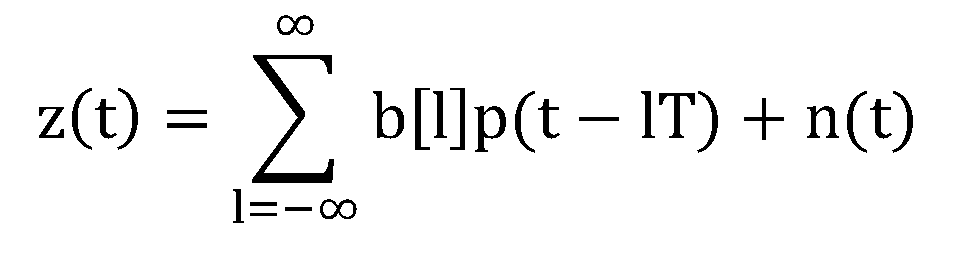
여기서, T는 심볼 전송 주기이고, b[l]은 데이터이다. 송신 파형 s(t)에 대한 채널의 응답은 ![]()
![]()
![]()
![]()
![]()
![]()
하기의 수학식 2는 z(t)가 수신기(202)를 통과하여 주기 T로 샘플링된 z[l]을 나타낸다.
![]()
![]()
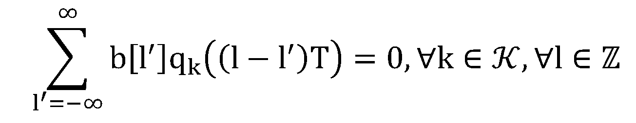
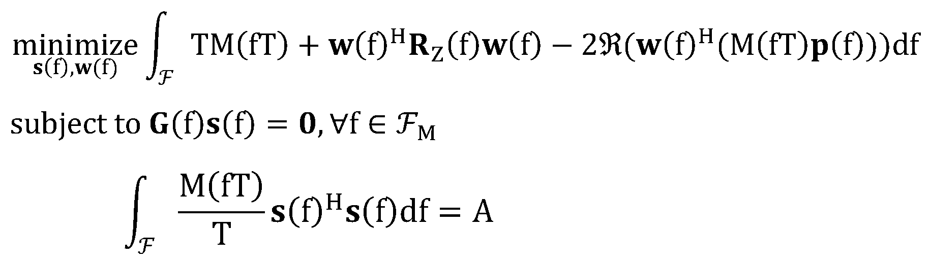
이하에서, 기존 통신시스템에 간섭 영향을 주지 않는 것과 동시에 공유 통신시스템의 데이터 전송 성능을 최대화할 수 있도록 송신 파형을 최적화시키는 방법을 제시한다. 즉, 하기의 수학식 3의 조건을 만족시키는 송신 파형을 찾아야 한다. 즉, 송신기(201)로부터 송출되는 신호의 전력이 제한되어 있고, 기존 통신시스템(100, 110, 120)에 대한 간섭을 0으로 하는 조건 하에서 MSE 값을 최소화하는 최적의 송신 파형을 찾는다. Hereinafter, a method of optimizing a transmission waveform to maximize data transmission performance of a shared communication system while not interfering with an existing communication system. That is, it is necessary to find a transmission waveform that satisfies the condition of
![]()
![]()

여기서, 도 2에서 보다 일반화된 K개의 기존의 통신시스템을 가정하였으며 К는 집합 {1,2, ..., K}로 정의되고, ![]()
![]()
![]()
![]()
![]()
![]()
여기서, 송신 전력이 클수록 수신기 출력의 MSE는 작아질 수 있으므로, 최적의 송수신단을 얻기 위하여 송신 전력을 A로 제한하는 것이 필요하다. Here, since the MSE of the receiver output may be smaller as the transmission power is larger, it is necessary to limit the transmission power to A in order to obtain an optimal transceiver.
이하에서는 상기 수학식 3을 만족하는 송신 파형 s(t)를 구한다.Hereinafter, the transmission waveform s (t) that satisfies the above equation (3) is obtained.
먼저, 수학식 3의 ![]()
![]()
![]()
![]()
여기서, ![]()
![]()
![]()
![]()
수학식 3의 해를 구하기 위하여 공유 통신시스템(200)에 수신되는 총 잡음 n(t)를 고려해야 한다. n(t)는 nI(t)와 nA(t)의 합이고, nI(t)는 도 2의 점선 (c)와 같이 기존 통신시스템(100, 110, 120)의 송신기(101, 111, 121)로부터 송출되는 신 호이며, 주기 T인 광의의 주기정상적(Wide-Sense Cyclostationary(이하, WSCS라 한다))이고, nA(t)는 일반적인 채널의 잡음이며, 광의의 정상적(Wide-Sense Stationary(이하, WSS라 한다))이다. 따라서, WSCS인 nI(t)와 WSS인 nA(t)의 합인 n(t)는 주기가 T인 WSCS가 된다. 이와 같이, WSCS인 잡음의 존재하에, 최소화된 MSE를 얻기 위하여 벡터화된 푸리에 변환(Vectorized Fourier Transform(이하, VFT라 한다))을 적용한다. 여기서, VFT는 하기의 수학식 5에 의하여 정의된다.In order to solve
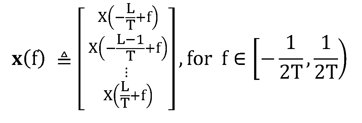
여기서, x(f)는 푸리에 변환을 원소로 가지는 벡터이고, 원소인 X(ζ)는 x(t)의 푸리에 변환식이다(![]()
![]()
![]()
![]()

![]()

![]()
![]()
![]()
![]()
![]()
수학식 3에 VFT를 적용하면 수학식 3은 하기의 수학식 6과 같이 바뀔 수 있다. When the VFT is applied to

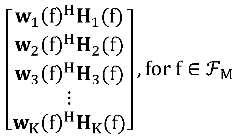
여기서, ![]()
![]()
![]()
![]()
![]()
![]()
![]()
![]()
또한, w k(f)는 k번째 기존 통신시스템의 수신기의 임펄스 응답이며, 행렬 H k(f)는 공유 통신시스템의 수신기로부터 k번째 기존 통신시스템까지 채널의 임펄스 응답을 이용하여 구한 대각 행렬로, ![]()

![]()
수학식 6은 전개 및 치환하여 하기의 수학식 7과 같이 나타낼 수 있다.
여기서, ![]()

![]()
LMMSE 수신기를 만드는 방법을 이용하여 최적화 문제인 수학식 7의 해를 구하면 최적의 수신 파형의 VFT w(f)를 구할 수 있다. 여기에서, LMMSE 수신기는 사이클릭 위너 필터(cyclic Wiener filter)이다. By solving the optimization problem (7) using the method of making the LMMSE receiver, the optimal VFT w (f) of the received waveform can be obtained. Here, the LMMSE receiver is a cyclic Wiener filter.
하기의 수학식 8은 사이클릭 위너 필터의 VFT이다.
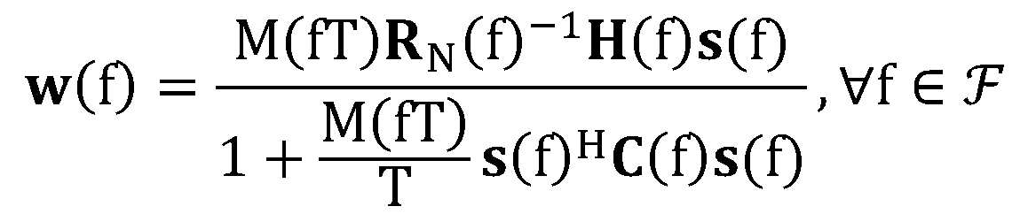
여기서, ![]()
![]()

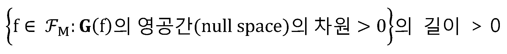
여기서, 송출 신호의 전력값이 A인 조건과 기존 통신시스템에 대한 간섭이 0인 조건을 모두 만족시키면서 수신기 출력의 평균제곱오차가 최소화되도록 하는 최적의 송신기의 송신 파형의 VFT s opt(f)가 0이 아닌 해를 가지기 위한 필요충분조건은 하기 수학식 10과 같다. 따라서, 하기 수학식 10을 만족할 경우에는 공유 통신시스템의 기존 통신시스템에 대한 간섭이 없으므로, 기존 통신시스템과 동일한 주파수 대역을 새로운 통신시스템이 공유할 수 있다. 즉, 하기 수학식 10을 만족할 경우에 기존 통신시스템에 대하여 간섭이 없는 공유 통신시스템을 추가할 수 있는 것으로 판단한다. Here, the VFT s opt (f) of the transmission waveform of the optimal transmitter for minimizing the mean square error of the receiver output while satisfying both the condition that the power value of the outgoing signal is A and the interference of the existing communication system is 0 is satisfied. The necessary and sufficient conditions for having a nonzero solution are as shown in
상기 수학식 9에서 최적의 송신 파형의 VFT s opt(f)은 하기의 수학식 11과 같다.In Equation 9, VFT s opt (f) of an optimal transmission waveform is represented by Equation 11 below.
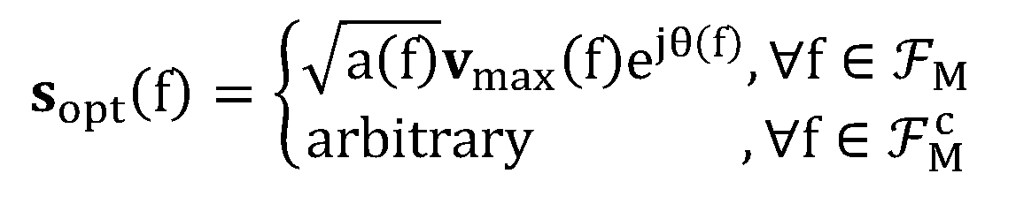
여기서, 에너지 할당값 a(f)는 s(f)H s(f)이고, 고유 벡터 v max(f)는 임시 행렬 P(f)C(f)의 가장 큰 고유값 λmax(f)의 고유 벡터이며, θ(f)는 임의로 정할 수 있다. 여기서, P(f)는 I N (f)-G(f)H(G(f)G(f)H)† G(f))이고, †는 pseudo inverse를 나타낸다. 또한, I N (f)는 N(f)×N(f)의 단위 행렬을 나타내고, N은 G(f)H의 열과 같은 차원이다. Here, the energy allocation a (f) is s (f) H s (f), and the eigenvector v max (f) is the largest eigenvalue λ max (f) of the temporary matrix P (f) C (f). Eigenvectors, and θ (f) can be arbitrarily determined. Where P (f) is I N (f) -G (f) H ( G (f) G (f) H ) † G (f)) and † represents pseudo inverse. In addition, I N (f) represents a unit matrix of N (f) × N (f), and N has the same dimension as a column of G (f) H.
또한, 상기 수학식 11을 이용하여 상기 수학식 9를 하기 수학식 12와 같이 나타낼 수 있다.In addition, Equation 9 may be expressed by

여기서, 최적의 송신 파형의 VFT s opt(f)을 구하기 위하여 최적의 에너지 할당값 aopt(f)를 알아야 한다. 상기 수학식 12의 해인 최적의 에너지 할당값 aopt(f)는 하기의 수학식 13과 같이 주어진다. Here, the optimal energy allocation value a opt (f) must be known in order to obtain the VFT s opt (f) of the optimal transmission waveform. The optimal energy allocation value a opt (f) which is the solution of

여기서, ![]()
![]()
![]()
![]()
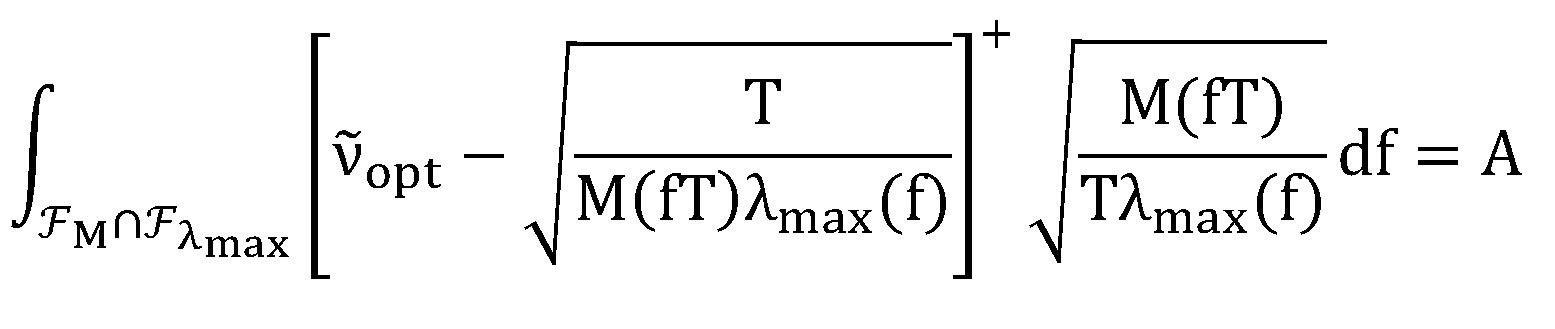
상기 수학식 14에서 구한 최적의 에너지 할당값 aopt(f)와 상기 수학식 8 및 수학식 11을 이용하면 하기 수학식 15와 같은 최적의 송신 파형의 VFT s opt(f), 최 적의 수신 파형의 VFT w opt(f)를 구할 수 있다.Using the optimal energy allocation value a opt (f) obtained from
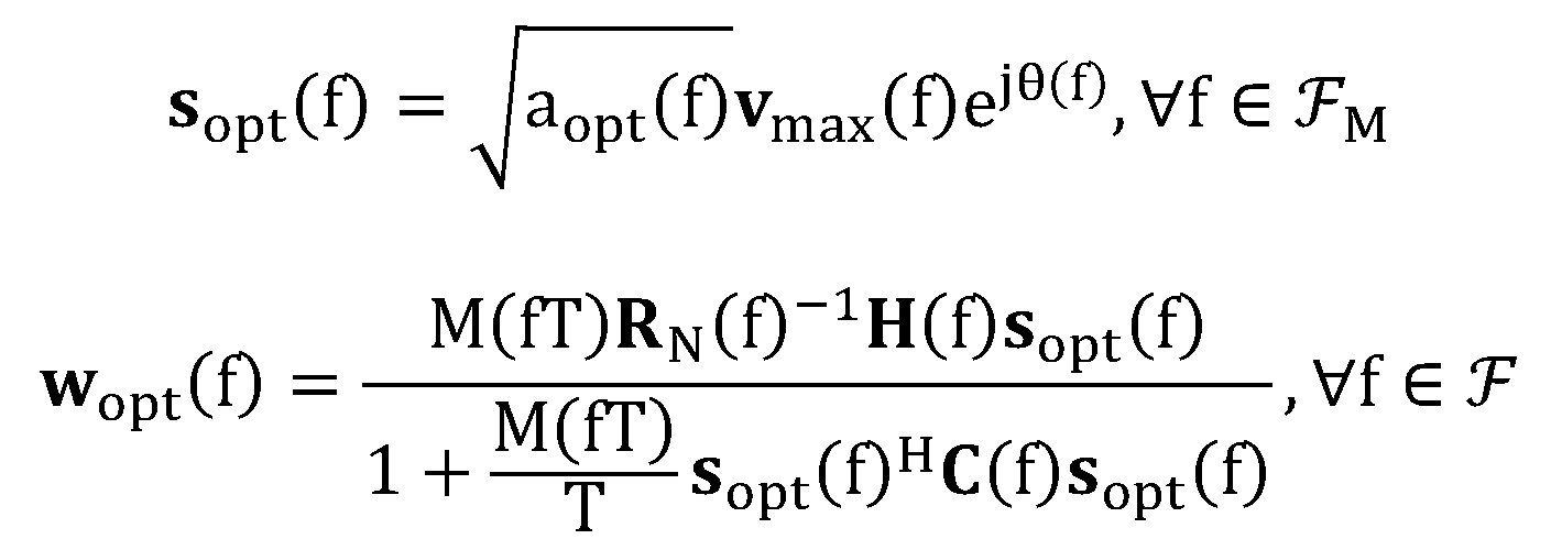
상기 최적의 송신 파형의 VFT s opt(f), 최적의 수신 파형의 VFT w opt(f)는 기존 통신시스템에 간섭을 주지 않으면서 송신기 및 수신기를 동시에 최적화하는 송신 파형 및 수신 파형의 VFT이다.The VFT s opt (f) of the optimal transmission waveform and the VFT w opt (f) of the optimal reception waveform are VFTs of the transmission waveform and the reception waveform which simultaneously optimize the transmitter and the receiver without interfering with the existing communication system.
도 3은 본 발명의 일 실시예에 따른 송신 파형을 사용했을 때 송신 신호의 전력 밀도와 수신 파형의 에너지 밀도를 나타낸 도면이다. 도 3에서 나타낸 바와 같이, 기존 통신시스템 1 및 기존 통신시스템 2로부터 간섭이 존재한다. 여기서, 송수신단의 대역폭은 1/T Hz, 신호대잡음비(SNR)는 10 dB, 기존 통신시스템에 의한 간섭 신호는 공유 통신시스템의 송출 신호보다 5 dB 더 높은 전력을 가지는 것으로 가정하였다. 3 is a view showing the power density of the transmission signal and the energy density of the reception waveform when using the transmission waveform according to an embodiment of the present invention. As shown in FIG. 3, there is interference from existing
본 발명에서는 송신 가능 주파수 대역에서 공유 통신시스템의 송신 파형을 최적화하기 위하여 가상의 기존 통신시스템(Virtual Legacy System) 개념을 도입한다. 공유 통신시스템에 있어서, 송신 가능 주파수 대역과 수신 가능 주파수 대역은 서로 다를 수 있다. 이때, 송신 가능 주파수 대역을 조금 더 넓게 잡는 대신 신호를 보내지 못하는 부분에 가상의 기존 통신시스템이 있는 것으로 등가적으로 바꾸 면 공유 통신시스템의 설계는 더욱 간단해진다. 상기 가상의 기존 통신시스템은 공유 통신시스템이 관심 주파수 대역 이외의 부분과 채널의 주파수 응답이 0인 주파수 대역 부분에 신호를 보내지 않도록 한다.In the present invention, a virtual legacy communication system (Virtual Legacy System) concept is introduced to optimize a transmission waveform of a shared communication system in a transmittable frequency band. In the shared communication system, the transmittable frequency band and the receivable frequency band may be different from each other. In this case, the design of the shared communication system becomes simpler if the existing communication system is virtually changed to the part where the signal cannot be transmitted, instead of holding the transmittable frequency band a little wider. The virtual existing communication system does not allow the shared communication system to signal a portion other than the frequency band of interest and a portion of the frequency band where the frequency response of the channel is zero.
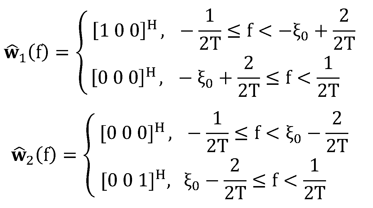
여기서, 가상의 기존 통신시스템에 직교하기 위해 행렬 G(f)에 추가되어야 할 행렬은 하기 수학식 16과 같이 주어진다.Here, the matrix to be added to the matrix G (f) to be orthogonal to the virtual existing communication system is given by Equation 16 below.
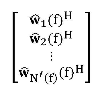
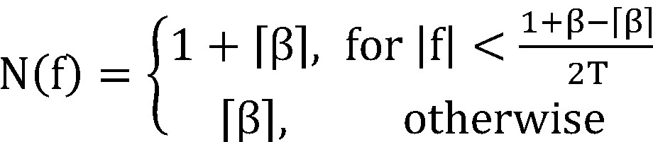
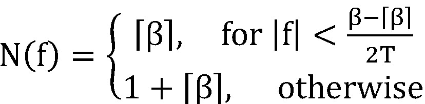
여기서, ![]()
![]()
도 4는 가상의 기존 통신시스템이 적용되는 주파수 대역을 나타낸 도면이다. 도 4에서 볼 수 있는 바와 같이, BT는 공유 통신시스템의 송신이 허용된 주파수 대역이고, BH C는 채널의 주파수 응답 H(ξ)가 0인 주파수 대역이며, BR은 공유 통신시스템의 수신기가 수신이 가능한 주파수 대역이다. 하기의 수학식 17은 도 4와 같이 주어진 가상의 기존 통신시스템의 수신 파형의 VFT를 정하는 방법을 나타낸다.4 is a diagram illustrating a frequency band to which a virtual existing communication system is applied. As can be seen in Figure 4, B T is a frequency band allowed for transmission of the shared communication system, B H C is a frequency band of the frequency response H (ξ) of the
상기 가상의 기존 통신시스템이 존재할 경우에, 상기 수학식 7의 행렬 G(f)는 하기의 수학식 18과 같이 다시 정의된다. When the virtual existing communication system exists, the matrix G (f) of Equation 7 is redefined as Equation 18 below.

여기서, 상기 가상의 기존 통신시스템 존재 하에서도 s opt(f)가 0이 아닌 해를 가지기 위한 필요충분조건은 행렬 G(f)가 상기의 수학식 18과 같이 다시 정의될 때 상기 수학식 10이 적용된다.Here, even in the presence of the virtual existing communication system, a necessary and sufficient condition for having a solution in which s opt (f) is not zero is represented by
도 5는 송신가능 주파수 대역이 수신가능 주파수 대역보다 작은 경우 본 발명의 일 실시예에 따른 송신 파형을 사용했을 때 송신신호의 전력밀도와 수신 파형의 에너지 밀도를 나타낸 도면이다. 도 5에서 나타낸 바와 같이, 최적의 송신신호가 차지하는 주파수 대역보다 넓은 대역에서 수신신호가 존재한다. 여기서, 송신단의 대역폭은 1/T Hz, 수신단의 대역폭은 1.5/T Hz, 신호대잡음비(SNR)는 10 dB, 기 존 통신시스템에 의한 간섭 신호는 공유 통신시스템의 송출 신호보다 5 dB 더 높은 전력을 가지는 것으로 가정하였다.5 is a diagram showing the power density of a transmission signal and the energy density of a reception waveform when a transmission waveform according to an embodiment of the present invention is used when the transmission frequency band is smaller than the reception frequency band. As shown in FIG. 5, the reception signal exists in a band wider than the frequency band occupied by the optimal transmission signal. Here, the bandwidth of the transmitter is 1 / T Hz, the bandwidth of the receiver is 1.5 / T Hz, the signal-to-noise ratio (SNR) is 10 dB, and the interference signal by the existing communication system is 5 dB higher than the transmission signal of the shared communication system. It is assumed to have.
도 6은 기존의 통신시스템에 간섭을 주지 않는 공유 통신시스템의 비트 오율 성능(BER)을 나타낸 그래프이다. 도 6에서 (a)는 기존 통신시스템이 공유 통신시스템에 대하여 미치는 간섭에서 주파수 대역 상관관계를 고려하지 않고 송수신단을 최적화한 경우의 그래프이고, (b)는 본 발명의 일 실시예에 따라 기존 통신시스템이 공유 통신시스템에 대하여 미치는 간섭에서 주파수 대역 상관관계를 고려하여 송수신단을 동시 최적화한 경우의 그래프이다. 도 6에서 알 수 있는 바와 같이, 본 발명의 일 실시예에 따라 공유 통신시스템의 송수신단을 동시 최적화한 경우에 공유 통신시스템의 비트 오율 성능이 현저히 우수하였다.6 is a graph illustrating the bit error rate performance (BER) of a shared communication system that does not interfere with an existing communication system. In FIG. 6, (a) is a graph of the case where the transceiver is optimized without considering the frequency band correlation in the interference of the existing communication system with respect to the shared communication system, and (b) is the existing according to an embodiment of the present invention. It is a graph of the simultaneous optimization of the transmitter and receiver considering the frequency band correlation in the interference of the communication system against the shared communication system. As can be seen in FIG. 6, the bit error rate performance of the shared communication system was remarkably excellent when the transceivers of the shared communication system were simultaneously optimized according to an embodiment of the present invention.
도 7은 기존 통신시스템의 비트 오율 성능을 나타낸 그래프이다. 도 7에서 (a)는 기존 통신시스템에 미치는 간섭을 고려하지 않고 공유 통신시스템을 설계한 경우의 그래프이고, (b)는 본 발명의 일 실시예에 따라 기존 통신시스템에 미치는 간섭을 고려하여 간섭이 0이 되도록 공유 통신시스템을 설계한 경우의 그래프이다. 도 7에서 알 수 있는 바와 같이, 본 발명의 일 실시예에 따라 공유 통신시스템이 기존 통신시스템에 미치는 간섭을 고려하여 공유 통신시스템을 설계한 경우에 기존 통신시스템의 비트 오율 성능이 현저히 우수하였다.7 is a graph showing the bit error rate performance of the existing communication system. In FIG. 7, (a) is a graph when a shared communication system is designed without considering interference on an existing communication system, and (b) is interference when considering interference on an existing communication system according to an embodiment of the present invention. This is a graph when the shared communication system is designed to be zero. As can be seen in FIG. 7, when the shared communication system is designed in consideration of interference of the shared communication system to the existing communication system, the bit error rate performance of the existing communication system is remarkably excellent.
본 발명은 하드웨어, 소프트웨어 또는 이들의 조합으로 구현될 수 있다. 하드웨어 구현에 있어, 상술한 기능을 수행하기 위해 디자인된 ASIC(application specific integrated circuit), DSP(digital signal processing), PLD(programmable logic device), FPGA(field programmable gate array), 프로세서, 제어기, 마이크로 프로세서, 다른 전자 유닛 또는 이들의 조합으로 구현될 수 있다. 소프트웨어 구현에 있어, 상술한 기능을 수행하는 모듈로 구현될 수 있다. 소프트웨어는 메모리 유닛에 저장될 수 있고, 프로세서에 의해 실행된다. 메모리 유닛이나 프로세서는 당업자에게 잘 알려진 다양한 수단을 채용할 수 있다.The invention can be implemented in hardware, software or a combination thereof. In hardware implementation, an application specific integrated circuit (ASIC), a digital signal processing (DSP), a programmable logic device (PLD), a field programmable gate array (FPGA), a processor, a controller, and a microprocessor are designed to perform the above functions. , Other electronic units, or a combination thereof. In the software implementation, the module may be implemented as a module that performs the above-described function. The software may be stored in a memory unit and executed by a processor. The memory unit or processor may employ various means well known to those skilled in the art.
이상, 본 발명의 바람직한 실시예에 대해 상세히 기술하였지만, 본 발명이 속하는 기술분야에 있어서 통상의 지식을 가진 사람이라면, 첨부된 청구 범위에 정의된 본 발명의 정신 및 범위를 벗어나지 않으면서 본 발명을 여러 가지로 변형 또는, 변경하여 실시할 수 있음을 알 수 있을 것이다. 따라서, 본 발명의 앞으로의 실시예들의 변경은 본 발명의 기술을 벗어날 수 없을 것이다.As mentioned above, preferred embodiments of the present invention have been described in detail, but those skilled in the art to which the present invention pertains should understand the present invention without departing from the spirit and scope of the present invention as defined in the appended claims. It will be appreciated that various modifications or changes can be made. Accordingly, modifications of the embodiments of the present invention will not depart from the scope of the present invention.
도 1은 기존 통신시스템과 공유 통신시스템의 개략도이다.1 is a schematic diagram of an existing communication system and a shared communication system.
도 2는 기존 통신시스템과 공유 통신시스템의 데이터 송수신 상태를 나타내는 도면이다. 2 is a diagram illustrating a data transmission and reception state between an existing communication system and a shared communication system.
도 3은 본 발명의 일 실시예에 따른 송수신 파형을 나타낸 도면이다.3 is a diagram illustrating a transmission and reception waveform according to an embodiment of the present invention.
도 4는 본 발명의 일 실시예에서 가상의 기존 통신시스템이 적용되는 주파수 대역을 나타낸 도면이다.4 is a diagram illustrating a frequency band to which a virtual existing communication system is applied in an embodiment of the present invention.
도 5는 본 발명의 일 실시예에서 송신 가능 주파수 대역과 수신 가능 주파수 대역이 다를 경우의 송수신 파형을 나타낸 도면이다.5 is a diagram illustrating transmission and reception waveforms when the transmittable frequency band and the receiveable frequency band are different according to an embodiment of the present invention.
도 6은 본 발명의 일 실시예에서 공유 통신시스템의 비트 오율 성능(BER)을 나타낸 그래프이다.6 is a graph illustrating the bit error rate performance (BER) of a shared communication system in an embodiment of the present invention.
도 7은 본 발명의 일 실시예에서 기존 통신시스템의 비트 오율 성능을 나타낸 그래프이다.7 is a graph showing the bit error rate performance of the existing communication system in an embodiment of the present invention.
Claims (8)


Priority Applications (2)
| Application Number | Priority Date | Filing Date | Title |
|---|---|---|---|
| KR1020080044864A KR100955766B1 (en) | 2008-05-15 | 2008-05-15 | Data transmission method sharing frequency band with existing communication system |
| US12/277,407 US8145133B2 (en) | 2008-05-15 | 2008-11-25 | Method and apparatus of sharing spectrum with legacy communication system |
Applications Claiming Priority (1)
| Application Number | Priority Date | Filing Date | Title |
|---|---|---|---|
| KR1020080044864A KR100955766B1 (en) | 2008-05-15 | 2008-05-15 | Data transmission method sharing frequency band with existing communication system |
Publications (2)
| Publication Number | Publication Date |
|---|---|
| KR20090119050A KR20090119050A (en) | 2009-11-19 |
| KR100955766B1 true KR100955766B1 (en) | 2010-04-30 |
Family
ID=41316621
Family Applications (1)
| Application Number | Title | Priority Date | Filing Date |
|---|---|---|---|
| KR1020080044864A Expired - Fee Related KR100955766B1 (en) | 2008-05-15 | 2008-05-15 | Data transmission method sharing frequency band with existing communication system |
Country Status (2)
| Country | Link |
|---|---|
| US (1) | US8145133B2 (en) |
| KR (1) | KR100955766B1 (en) |
Families Citing this family (29)
| Publication number | Priority date | Publication date | Assignee | Title |
|---|---|---|---|---|
| US8224364B2 (en) * | 2009-11-23 | 2012-07-17 | Motorola Solutions, Inc. | Method for quieting and sensing in a secondary communications system |
| US8749714B2 (en) * | 2010-01-05 | 2014-06-10 | Qualcomm Incorporated | Distinguishing and communicating between white space devices transmitting ATSC-compatible signals |
| EP2695412B1 (en) | 2011-04-08 | 2016-09-14 | Telefonaktiebolaget LM Ericsson (publ) | Method and arrangement for white space device transmission |
| US9124397B2 (en) | 2013-03-15 | 2015-09-01 | Samsung Electronics Co., Ltd. | Wireless communication system with interference mitigation mechanism and method of operation thereof |
| US20160037505A1 (en) * | 2014-07-31 | 2016-02-04 | Purdue Research Foundation | Digital radio system |
| CN104104459B (en) * | 2014-08-07 | 2016-03-02 | 中国电子科技集团公司第五十四研究所 | Based on the wide-band frequency spectrum sensing method of multiple window spectrum estimation |
| TWI674027B (en) | 2014-09-24 | 2019-10-01 | 日商新力股份有限公司 | Telecommunications apparatus and methods |
| AU2015101185A4 (en) * | 2015-07-26 | 2015-10-08 | Macau University Of Science And Technology | Power control method for spectrum sharing cognitive radio network |
| US12294866B2 (en) | 2020-05-01 | 2025-05-06 | Digital Global Systems, Inc. | System, method, and apparatus for providing dynamic, prioritized spectrum management and utilization |
| US12219365B2 (en) | 2020-05-01 | 2025-02-04 | Digital Global Systems, Inc. | System, method, and apparatus for providing dynamic, prioritized spectrum management and utilization |
| US11638160B2 (en) | 2020-05-01 | 2023-04-25 | Digital Global Systems, Inc. | System, method, and apparatus for providing dynamic, prioritized spectrum management and utilization |
| US12309599B2 (en) | 2020-05-01 | 2025-05-20 | Digital Global Systems, Inc. | System, method, and apparatus for providing dynamic, prioritized spectrum management and utilization |
| US12133082B2 (en) | 2020-05-01 | 2024-10-29 | Digital Global Systems, Inc. | System, method, and apparatus for providing dynamic, prioritized spectrum management and utilization |
| US12262213B2 (en) | 2020-05-01 | 2025-03-25 | Digital Global Systems, Inc. | System, method, and apparatus for providing dynamic, prioritized spectrum management and utilization |
| US12096230B2 (en) | 2020-05-01 | 2024-09-17 | Digital Global Systems, Inc. | System, method, and apparatus for providing dynamic, prioritized spectrum management and utilization |
| US12212974B2 (en) | 2020-05-01 | 2025-01-28 | Digital Global Systems, Inc. | System, method, and apparatus for providing dynamic, prioritized spectrum management and utilization |
| US12302113B2 (en) | 2020-05-01 | 2025-05-13 | Digital Global Systems, Inc. | System, method, and apparatus for providing dynamic, prioritized spectrum management and utilization |
| US12192777B2 (en) | 2020-05-01 | 2025-01-07 | Digital Global Systems, Inc. | System, method, and apparatus for providing dynamic, prioritized spectrum management and utilization |
| US11653213B2 (en) | 2020-05-01 | 2023-05-16 | Digital Global Systems. Inc. | System, method, and apparatus for providing dynamic, prioritized spectrum management and utilization |
| US11700533B2 (en) | 2020-05-01 | 2023-07-11 | Digital Global Systems, Inc. | System, method, and apparatus for providing dynamic, prioritized spectrum management and utilization |
| US12256225B2 (en) | 2020-05-01 | 2025-03-18 | Digital Global Systems, Inc. | System, method, and apparatus for providing dynamic, prioritized spectrum management and utilization |
| US12513528B2 (en) | 2020-05-01 | 2025-12-30 | Digital Global Systems, Inc. | System, method, and apparatus for providing dynamic, prioritized spectrum management and utilization |
| US12323812B2 (en) | 2020-05-01 | 2025-06-03 | Digital Global Systems, Inc. | System, method, and apparatus for providing dynamic, prioritized spectrum management and utilization |
| US11395149B2 (en) | 2020-05-01 | 2022-07-19 | Digital Global Systems, Inc. | System, method, and apparatus for providing dynamic, prioritized spectrum management and utilization |
| US11849332B2 (en) | 2020-05-01 | 2023-12-19 | Digital Global Systems, Inc. | System, method, and apparatus for providing dynamic, prioritized spectrum management and utilization |
| US11665547B2 (en) | 2020-05-01 | 2023-05-30 | Digital Global Systems, Inc. | System, method, and apparatus for providing dynamic, prioritized spectrum management and utilization |
| US12262211B2 (en) | 2020-05-01 | 2025-03-25 | Digital Global Systems, Inc. | System, method, and apparatus for providing dynamic, prioritized spectrum management and utilization |
| US12413984B2 (en) | 2020-05-01 | 2025-09-09 | Digital Global Systems, Inc. | System, method, and apparatus for providing dynamic, prioritized spectrum management and utilization |
| US12177679B2 (en) | 2020-05-01 | 2024-12-24 | Digital Global Systems, Inc. | System, method, and apparatus for providing dynamic, prioritized spectrum management and utilization |
Citations (2)
| Publication number | Priority date | Publication date | Assignee | Title |
|---|---|---|---|---|
| KR20040110504A (en) * | 2003-06-19 | 2004-12-31 | 삼성전자주식회사 | UWB wireless transmitter and receiver using UWB linear FM signals having opposite slopes and method thereof |
| JP2006222665A (en) | 2005-02-09 | 2006-08-24 | Ntt Docomo Inc | Control device in wireless communication transmitting / receiving device and wireless communication transmitting / receiving method |
Family Cites Families (1)
| Publication number | Priority date | Publication date | Assignee | Title |
|---|---|---|---|---|
| US7483711B2 (en) * | 2002-10-24 | 2009-01-27 | Bbn Technologies Corp | Spectrum-adaptive networking |
-
2008
- 2008-05-15 KR KR1020080044864A patent/KR100955766B1/en not_active Expired - Fee Related
- 2008-11-25 US US12/277,407 patent/US8145133B2/en not_active Expired - Fee Related
Patent Citations (2)
| Publication number | Priority date | Publication date | Assignee | Title |
|---|---|---|---|---|
| KR20040110504A (en) * | 2003-06-19 | 2004-12-31 | 삼성전자주식회사 | UWB wireless transmitter and receiver using UWB linear FM signals having opposite slopes and method thereof |
| JP2006222665A (en) | 2005-02-09 | 2006-08-24 | Ntt Docomo Inc | Control device in wireless communication transmitting / receiving device and wireless communication transmitting / receiving method |
Also Published As
| Publication number | Publication date |
|---|---|
| US20090286480A1 (en) | 2009-11-19 |
| KR20090119050A (en) | 2009-11-19 |
| US8145133B2 (en) | 2012-03-27 |
Similar Documents
| Publication | Publication Date | Title |
|---|---|---|
| KR100955766B1 (en) | Data transmission method sharing frequency band with existing communication system | |
| AU2017353033B2 (en) | Method for subspace selection, user equipment and computer-readable storage medium | |
| EP2860925B1 (en) | Method and full-duplex communication device for acquiring channel response of self-interfering channel | |
| KR102216777B1 (en) | Modulation and equalization in an orthonormal time-frequency shifting communications system | |
| US9548840B2 (en) | Modulation and equalization in an orthonormal time-frequency shifting communications system | |
| TWI638556B (en) | Method for channel estimation in a wireless communication system, communication unit, terminal and communication system | |
| CN103516407A (en) | Transmission mode selection method, antenna transmitting and receiving combination determination method, apparatus and system thereof | |
| US8331481B2 (en) | Method for channel state feedback by quantization of time-domain coefficients | |
| US10785060B2 (en) | Efficient channel estimation and symbol detection for massive MIMO-OFDM | |
| CN106664273A (en) | Interference cancellation in MIMO same channel full-duplex transceivers | |
| Xia et al. | A practical SDMA protocol for 60 GHz millimeter wave communications | |
| KR100712069B1 (en) | Method for Estimating Channel of Multi-Antenna System | |
| CN119363172A (en) | Transparent coexistence method of data transmission across protocols based on precoding | |
| US8559880B2 (en) | Method and apparatus of improving capacity of channel | |
| KR100636314B1 (en) | Apparatus and method for signal transmission in multi-antenna system | |
| KR100984737B1 (en) | Method for cancelling interference signal of base station in a multiuser mimo relay system | |
| US20080084944A1 (en) | Interference cancellation and spatial multiplexing in wireless local area networks with multiple-input-multiple-output wireless stations | |
| CN114727317B (en) | High-spectral efficiency communication system for realizing relay forwarding by using D2D communication equipment | |
| TR2024017210A2 (en) | INTELLIGENT INTERFERENCE REDUCTION IN FULL-DUPLEX XL-MIMO NETWORKS | |
| KR101018162B1 (en) | Method and device for data transmission sharing frequency band with existing system in multi-antenna system | |
| Pradhan et al. | Full-duplex transceiver for future cellular network: A smart antenna approach | |
| Benyoucef | Pre-coded OFDM in Power Line Communication | |
| Tian et al. | Compressed sensing techniques for dynamic resource allocation in wideband cognitive networks | |
| KR20120056906A (en) | Method and apparatus of improving capacity of channel in overloaded code division multiple access |
Legal Events
| Date | Code | Title | Description |
|---|---|---|---|
| A201 | Request for examination | ||
| PA0109 | Patent application |
St.27 status event code: A-0-1-A10-A12-nap-PA0109 |
|
| PA0201 | Request for examination |
St.27 status event code: A-1-2-D10-D11-exm-PA0201 |
|
| D13-X000 | Search requested |
St.27 status event code: A-1-2-D10-D13-srh-X000 |
|
| D14-X000 | Search report completed |
St.27 status event code: A-1-2-D10-D14-srh-X000 |
|
| E902 | Notification of reason for refusal | ||
| PE0902 | Notice of grounds for rejection |
St.27 status event code: A-1-2-D10-D21-exm-PE0902 |
|
| P11-X000 | Amendment of application requested |
St.27 status event code: A-2-2-P10-P11-nap-X000 |
|
| P13-X000 | Application amended |
St.27 status event code: A-2-2-P10-P13-nap-X000 |
|
| PG1501 | Laying open of application |
St.27 status event code: A-1-1-Q10-Q12-nap-PG1501 |
|
| E701 | Decision to grant or registration of patent right | ||
| PE0701 | Decision of registration |
St.27 status event code: A-1-2-D10-D22-exm-PE0701 |
|
| GRNT | Written decision to grant | ||
| PR0701 | Registration of establishment |
St.27 status event code: A-2-4-F10-F11-exm-PR0701 |
|
| PR1002 | Payment of registration fee |
St.27 status event code: A-2-2-U10-U11-oth-PR1002 Fee payment year number: 1 |
|
| PG1601 | Publication of registration |
St.27 status event code: A-4-4-Q10-Q13-nap-PG1601 |
|
| FPAY | Annual fee payment |
Payment date: 20130410 Year of fee payment: 4 |
|
| PR1001 | Payment of annual fee |
St.27 status event code: A-4-4-U10-U11-oth-PR1001 Fee payment year number: 4 |
|
| PN2301 | Change of applicant |
St.27 status event code: A-5-5-R10-R13-asn-PN2301 St.27 status event code: A-5-5-R10-R11-asn-PN2301 |
|
| R18-X000 | Changes to party contact information recorded |
St.27 status event code: A-5-5-R10-R18-oth-X000 |
|
| LAPS | Lapse due to unpaid annual fee | ||
| PC1903 | Unpaid annual fee |
St.27 status event code: A-4-4-U10-U13-oth-PC1903 Not in force date: 20140424 Payment event data comment text: Termination Category : DEFAULT_OF_REGISTRATION_FEE |
|
| PC1903 | Unpaid annual fee |
St.27 status event code: N-4-6-H10-H13-oth-PC1903 Ip right cessation event data comment text: Termination Category : DEFAULT_OF_REGISTRATION_FEE Not in force date: 20140424 |
|
| PN2301 | Change of applicant |
St.27 status event code: A-5-5-R10-R13-asn-PN2301 St.27 status event code: A-5-5-R10-R11-asn-PN2301 |
|
| PN2301 | Change of applicant |
St.27 status event code: A-5-5-R10-R13-asn-PN2301 St.27 status event code: A-5-5-R10-R11-asn-PN2301 |
|
| R18-X000 | Changes to party contact information recorded |
St.27 status event code: A-5-5-R10-R18-oth-X000 |