KR100936202B1 - Pattern diversity to support a mimo receiver and associated methods - Google Patents
Pattern diversity to support a mimo receiver and associated methods Download PDFInfo
- Publication number
- KR100936202B1 KR100936202B1 KR1020087009621A KR20087009621A KR100936202B1 KR 100936202 B1 KR100936202 B1 KR 100936202B1 KR 1020087009621 A KR1020087009621 A KR 1020087009621A KR 20087009621 A KR20087009621 A KR 20087009621A KR 100936202 B1 KR100936202 B1 KR 100936202B1
- Authority
- KR
- South Korea
- Prior art keywords
- source signals
- mixing matrix
- antenna
- receive
- different
- Prior art date
Links
Images


Classifications
-
- H—ELECTRICITY
- H04—ELECTRIC COMMUNICATION TECHNIQUE
- H04B—TRANSMISSION
- H04B7/00—Radio transmission systems, i.e. using radiation field
- H04B7/02—Diversity systems; Multi-antenna system, i.e. transmission or reception using multiple antennas
- H04B7/04—Diversity systems; Multi-antenna system, i.e. transmission or reception using multiple antennas using two or more spaced independent antennas
- H04B7/0413—MIMO systems
- H04B7/0456—Selection of precoding matrices or codebooks, e.g. using matrices antenna weighting
- H04B7/0486—Selection of precoding matrices or codebooks, e.g. using matrices antenna weighting taking channel rank into account
-
- H—ELECTRICITY
- H04—ELECTRIC COMMUNICATION TECHNIQUE
- H04B—TRANSMISSION
- H04B7/00—Radio transmission systems, i.e. using radiation field
- H04B7/02—Diversity systems; Multi-antenna system, i.e. transmission or reception using multiple antennas
- H04B7/10—Polarisation diversity; Directional diversity
Landscapes
- Engineering & Computer Science (AREA)
- Computer Networks & Wireless Communication (AREA)
- Signal Processing (AREA)
- Radio Transmission System (AREA)
- Mobile Radio Communication Systems (AREA)
Abstract
MIMO 통신 시스템은 송신기, 및 송신기에 연결되며 M개의 소스 신호들을 송신하기 위한 M개의 안테나 소자들을 갖는 송신 안테나 어레이를 포함한다. 수신 안테나 어레이는 수신기에 연결되어 있으며, M개의 소스 신호들의 M개 이상의 상이한 합산들을 수신하는 N개의 안테나 소자를 갖고 있으며, 여기서, N은 M보다 작다. 신호 분리 처리기는 수신기에 연결되어, 혼합 행렬이 적어도 M과 동일한 계수를 갖도록 M개의 소스 신호들의 M개 이상의 상이한 합산들을 포함하는 혼합 행렬을 형성한다. 신호 분리 처리기는 혼합 행렬로부터 원하는 소스 신호들을 분리한다.

The MIMO communication system includes a transmitter and a transmit antenna array coupled to the transmitter and having M antenna elements for transmitting M source signals. The receiving antenna array is connected to the receiver and has N antenna elements that receive M or more different summations of the M source signals, where N is less than M. The signal separation processor is coupled to the receiver to form a mixing matrix comprising M or more different summations of the M source signals such that the mixing matrix has a coefficient equal to at least M. The signal separation processor separates the desired source signals from the mixing matrix.
Description
본 발명은 통신 시스템 분야에 관한 것으로, 보다 구체적으로는 콤팩트한 안테나 어레이를 이용하여 동작하는 다중 입력 다중 출력(MIMO: multiple-input multiple-output) 수신기에 관한 것이다. TECHNICAL FIELD The present invention relates to the field of communications systems, and more particularly, to a multiple-input multiple-output (MIMO) receiver operating using a compact antenna array.
다중 입력 다중 출력(MIMO) 무선 통신 시스템은 송신기에 복수의 안테나 소자 및 수신기에 복수의 안테나 소자를 포함한다. 각각의 안테나 어레이는 자신과 관련된 안테나 소자들에 기초해서 송신기 및 수신기에 형성된다. A multiple input multiple output (MIMO) wireless communication system includes a plurality of antenna elements in a transmitter and a plurality of antenna elements in a receiver. Each antenna array is formed in a transmitter and a receiver based on the antenna elements associated with it.
다중 경로가 많은 환경에서의 다양한 산란 물체들의 존재로 인해, 각 신호들이 다중 경로 전파를 경험하는 것과 같은 환경에서 안테나 소자들이 사용된다. 수신 안테나 소자들이 송신된 신호들을 포착하면, 그 후, 신호 처리 기술이 적용되어 송신된 신호를 분리하고 사용자 데이터를 복구한다.Due to the presence of various scattering objects in a multipath environment, antenna elements are used in an environment where each signal experiences multipath propagation. Once the receiving antenna elements capture the transmitted signals, signal processing techniques are then applied to separate the transmitted signals and recover the user data.
신호 처리 기술은 블라인드 소스 분리(BSS; blind source separation) 프로세스일 수 있다. 이 분리가 송신 신호, 송신 신호의 소스, 그리고 이 송신 신호에 영향을 미치는 전파 채널의 영향에 대해 제한된 정보로 수행되기 때문에, 이러한 분리는 "블라인드(blind)"하다. 통상 이용되는 3가지 블라인드 신호 분리 기술은 주성분 분석(PCA; principal component analysis), 독립 성분 분석(ICA; independent component analysis), 및 고유치 분해(SVD; singular value decomposition)이다.The signal processing technique may be a blind source separation (BSS) process. This separation is "blind" because this separation is performed with limited information about the transmission signal, the source of the transmission signal, and the influence of the propagation channel affecting the transmission signal. Three blind signal separation techniques commonly used are principal component analysis (PCA), independent component analysis (ICA), and singular value decomposition (SVD).
MIMO 통신 시스템은 송신기와 수신기 사이의 무선 링크의 용량이 개선될 수 있다는 점에서 이점이 있다. 다중 경로가 많은 환경은 송신기와 수신기 사이에서 다중 직교 채널이 생성되는 것을 가능하게 한다. 그 후, 단일 사용자에 대한 데이터는 이들 채널들 상에서 평행하게 전파를 통해, 그리고 동시에 동일 대역폭을 이용하여 송신될 수 있다. MIMO communication systems are advantageous in that the capacity of the radio link between the transmitter and the receiver can be improved. Multipathy environments enable multiple orthogonal channels to be created between the transmitter and the receiver. The data for a single user can then be transmitted over the air on these channels in parallel and simultaneously using the same bandwidth.
현재의 MIMO 통신 시스템은 형성될 수 있는 직교 채널의 수가 줄어들지 않도록 공간 다이버시티 안테나 소자를 사용한다. 이와 같은 구현이 갖는 문제는 MIMO 통신 시스템의 성능이 사용되는 안테나 소자의 수에 일반적으로 비례한다는 것이다. Current MIMO communication systems use spatial diversity antenna elements such that the number of orthogonal channels that can be formed is not reduced. The problem with such an implementation is that the performance of the MIMO communication system is generally proportional to the number of antenna elements used.
안테나 소자의 수가 증가하면 MIMO 통신 시스템의 안테나 어레이의 크기도 증가한다. MIMO 수신기가 소형 포터블 통신 장치내에 구현되는 경우, 다수의 안테나 소자에 대한 이용 가능한 용적이 거의 없고, 통신 장치의 외부에 안테나 소자를 장착하는 것은 사용자에게 문제가 된다. As the number of antenna elements increases, the size of the antenna array of the MIMO communication system also increases. When a MIMO receiver is implemented in a small portable communication device, there is little volume available for many antenna elements, and mounting the antenna element outside of the communication device is a problem for the user.
MIMO 수신기에 보다 콤팩트한 안테나 어레이를 제공하는 한 가지 방식이 미국 특허 번호 제6,870,515호에 개시되어 있다. 공간 다이버시티 안테나 소자들을 이용하는 대신에, 편파 다이버시티(polarization diversity)가 이용된다. 빽빽하게 이격된 안테나 소자들이 사용되기 때문에, 콤팩트한 안테나 어레이가 MIMO 수신기 에 제공되는 것을 가능하게 한다. One way of providing a more compact antenna array for a MIMO receiver is disclosed in US Pat. No. 6,870,515. Instead of using spatial diversity antenna elements, polarization diversity is used. Since tightly spaced antenna elements are used, it is possible to provide a compact antenna array to the MIMO receiver.
보다 콤팩트한 안테나 어레이가 제공되었지만, MIMO 통신 시스템의 성능은 여전히 송신기에서의 안테나 소자들의 수보다 크거나 같은, 수신기에서의 안테나 소자들의 수에 기초한다. 예컨대, 상기 미국 특허 제6,870,515호는 수신 안테나 소자들의 수가 송신 안테나 소자들의 수보다 크거나 같은 것으로 개시하고 있다. Although a more compact antenna array has been provided, the performance of a MIMO communication system is still based on the number of antenna elements at the receiver, which is greater than or equal to the number of antenna elements at the transmitter. For example, US Pat. No. 6,870,515 discloses that the number of receive antenna elements is greater than or equal to the number of transmit antenna elements.
전술한 배경 기술을 고려하여, 본 발명의 목적은 MIMO 송신기의 안테나 소자들의 수와 비교해서 MIMO 수신기의 안테나 소자들의 수를 줄이면서 여전히 강력한 MIMO 통신 시스템을 제공하는 것이다. In view of the foregoing background, it is an object of the present invention to provide a still powerful MIMO communication system while reducing the number of antenna elements of a MIMO receiver as compared to the number of antenna elements of a MIMO transmitter.
본 발명에 따른 이러한 목적, 특징 및 이점들과 다른 목적, 특징 및 이점들은 송신기 및 송신기에 연결되고 M개의 소스 신호들을 송신하기 위한 M개의 안테나 소자를 포함하는 송신 안테나 어레이를 포함하는 MIMO 통신 시스템에 의해 제공된다. These objects, features and advantages and other objects, features and advantages according to the present invention are directed to a MIMO communication system comprising a transmitter and an antenna array coupled to the transmitter and including an M antenna element for transmitting M source signals. Provided by
수신 측에서, 수신 안테나 어레이는 수신기에 연결되고 M개의 소스 신호들의 M개 이상의 상이한 합산들을 수신하는 N개의 안테나 소자를 포함하되, N은 M보다 작다. 신호 분리 처리기는 수신기에 연결되어, 혼합 행렬이 적어도 M과 동일한 계수(rank)를 갖도록 M개의 소스 신호들의 M개 이상의 상이한 합산들을 포함하는 혼합 행렬을 형성할 수 있다. 신호 분리 처리기는 혼합 행렬로부터 원하는 소스 신호들을 분리한다.At the receiving side, the receiving antenna array includes N antenna elements connected to the receiver and receiving at least M different summations of the M source signals, where N is less than M. The signal separation processor may be coupled to the receiver to form a mixing matrix comprising M or more different summations of the M source signals such that the mixing matrix has at least the same rank as M. The signal separation processor separates the desired source signals from the mixing matrix.
신호 분리 처리기는 블라인드 신호 분리 처리기일 수 있다. 블라인드 신호 분리 처리기는 주성분 분석(PCA), 독립 성분 분석(ICA), 및 고유치 분해(SVD) 중 적어도 하나에 기초하여 혼합 행렬로부터 원하는 소스 신호들을 분리할 수 있다. The signal separation processor may be a blind signal separation processor. The blind signal separation processor may separate the desired source signals from the mixing matrix based on at least one of principal component analysis (PCA), independent component analysis (ICA), and eigenvalue decomposition (SVD).
다른 방법으로, 신호 분리 처리기는 정보 기반 처리 신호 추출 프로세스에 기초하여 혼합 행렬로부터 원하는 소스 신호들을 분리할 수 있다. 정보 기반 신호 분리(추출) 프로세스는 ZF(zero forcing) 프로세스, 및 MMSE(minimum mean squared estimation) 프로세스 중 적어도 하나에 기초하여 혼합 행렬로부터 원하는 소스 신호를 분리할 수 있다. Alternatively, the signal separation processor may separate the desired source signals from the mixing matrix based on the information based processing signal extraction process. The information-based signal separation (extraction) process may separate a desired source signal from the mixing matrix based on at least one of a zero forcing (ZF) process and a minimum mean squared estimation (MMSE) process.
수신 안테나 어레이는 N개의 안테나 소자들을 이용하여 M개의 소스 신호들의 M개의 상이한 합산들을 바람직하게 수신하며, N < M이다. N개의 안테나 소자들은 M개의 소스 신호들의 M개의 상이한 합산들을 수신하기 위하여 M개 이상의 상이한 안테나 패턴들을 발생시킨다. 수신 안테나 어레이에서 N개의 안테나 소자들에 의해 수신되는, M개의 소스 신호들의 M개의 상이한 합산들은 혼합 행렬이 적어도 M과 동일한 계수를 갖도록 혼합 행렬을 채우는데(populate) 이용된다. The receiving antenna array preferably receives M different summations of M source signals using N antenna elements, where N < M. The N antenna elements generate M or more different antenna patterns to receive M different summations of the M source signals. M different summations of the M source signals, received by the N antenna elements in the receive antenna array, are used to populate the mixing matrix such that the mixing matrix has at least the same coefficient as M.
혼합 행렬의 계수는 얼마나 많은 신호들이 실제로 분리될 수 있는지를 결정한다. 계수가 클수록 보다 많은 신호가 분리될 수 있다. 결과적으로, 송신 어레이에서의 M개의 안테나 소자들보다 적은 N개의 안테나 소자들을 갖는 콤패트한 안테나 어레이가 MIMO 수신기에 의해 이용될 수 있으면서, 여전히 강력한 MIMO 통신 시스템을 제공할 수 있다.The coefficients of the mixing matrix determine how many signals can actually be separated. The larger the coefficient, the more signals can be separated. As a result, a compact antenna array having fewer N antenna elements than M antenna elements in the transmit array can be used by the MIMO receiver, while still providing a powerful MIMO communication system.
수신 안테나 어레이의 복수의 다른 실시예들이 있다. N개의 안테나 소자들이 위상 어레이(phased array)를 형성하도록 상관화될 수 있다. 다른 실시예에서, N개의 상관화된 안테나 소자들은 스위치형 빔 안테나를 형성하기 위하여, 1개 이상의 능동 안테나 소자들과 N-1개까지의 수동 안테나 소자들을 포함할 수 있다. 또한, N개의 상관화된 안테나 소자들 중 적어도 2개의 상관화된 안테나 소자들이 상이한 편파(polarization)를 가질 수 있다. There are a plurality of other embodiments of the receiving antenna array. N antenna elements may be correlated to form a phased array. In another embodiment, the N correlated antenna elements may include one or more active antenna elements and up to N-1 passive antenna elements to form a switched beam antenna. In addition, at least two correlated antenna elements of the N correlated antenna elements may have different polarizations.
수신 안테나 어레이의 다른 실시예는 M개의 소스 신호들의 수신된 M개의 상이한 합산들에서 승수 효과를 가질 수 있다. 이것은 수신 안테나 어레이에서의 N개의 안테나 소자들의 갯수를 증가시킬 필요없이, 혼합 행렬의 계수를 바람직하게 추가로 증가시킬 수 있게 한다. 혼합 행렬의 계수를 증가시킴으로써, 보다 많은 신호가 블라인드 신호 분리 처리기에 의해 분리될 수 있다. Another embodiment of the receive antenna array may have a multiplier effect at the received M different summations of the M source signals. This makes it possible to preferably further increase the coefficient of the mixing matrix, without having to increase the number of N antenna elements in the receive antenna array. By increasing the coefficients of the mixing matrix, more signals can be separated by the blind signal separation processor.
M개의 소스 신호들의 수신된 M개의 수신된 상이한 합산들의 갯수에서의 승수 효과는 이하의 것 중 하나 또는 조합을 이용하여 실현될 수 있다. 어레이 편향은 소스 신호들의 부가적인 합산들을 수신하기 위하여 안테나 패턴의 고도를 변경하는 것을 수반한다. 경로 선택은 혼합 행렬을 채우는데 이용되는 소스 신호들의 모든 합산들이 상관 처리되고 및/또는 통계적으로 독립되도록 수행될 수 있다. 또한 혼합 행렬을 추가로 채우기 위하여 신호 분할이 이용될 수 있다. 상이한 합산 신호들은 확산 코드들을 이용하여 분할될 수 있거나, 또는 동상(I) 성분 및 직교 위상(Q) 성분으로 분할될 수 있다. The multiplier effect on the number of received M received different summations of the M source signals can be realized using one or a combination of the following. Array deflection involves changing the height of the antenna pattern to receive additional summations of the source signals. Path selection may be performed such that all summations of the source signals used to populate the mixing matrix are correlated and / or statistically independent. Signal segmentation can also be used to further fill the mixing matrix. Different summation signals may be split using spreading codes, or may be split into in-phase (I) components and quadrature phase (Q) components.
M개의 선형 독립적 합산은 M개의 송신 안테나 소자들의 완전한 MIMO 구현을 지원하는데 필요한 최소한의 것이지만, M을 초과하는 것에 이점이 있다. 예를 들어, 수신 안테나 어레이에서의 N개의 안테나 소자들 모두가 M개의 선형 독립적 합산들을 수신하도록 방향 지어질 수 있는 것은 아니다. 마찬가지로, 수신된 합산 모두가 충분히 선형 독립적인 것은 아니다. M linearly independent summation is the minimum necessary to support a full MIMO implementation of M transmit antenna elements, but has an advantage over M. For example, not all N antenna elements in the receive antenna array can be directed to receive M linear independent summations. Likewise, not all received sums are sufficiently linearly independent.
추가로, 방해하는 간섭 소스 또는 잡음 소스가 있다면, 이들 신호를 분리하는데 부가적인 혼합 행렬 계수가 필요할 수 있다. 간섭 소스 또는 잡음 소스를 분리하는 또 다른 이점은 결과적으로 신호 대 잡음 비를 감소시켜, 데이터 전송률을 높이고, 에러율을 낮추며, 및/또는 송신 전력을 감소가능하게 한다. In addition, if there are interfering interference sources or noise sources, additional mixing matrix coefficients may be needed to separate these signals. Another advantage of isolating interference sources or noise sources results in a reduction in signal-to-noise ratio, resulting in higher data rates, lower error rates, and / or reduced transmit power.
위의 2가지 이유로, 이용가능한 채널의 갯수와 관련되어 있는 M 보다 더 크게 혼합 행렬의 계수를 증가시키는 것이 바람직하다. 통상의 M개에 L개의 부가적인 합의 이러한 증가는 보다 강력한 MIMO 구현을 제공할 수 있다. 혼합 행렬을 증가시키는데 이용가능한 수단에 의존하여, 수신 안테나 소자들의 갯수는 종래의 MIMO의 M개보다 여전히 적을 수 있거나, 또는 혼합 행렬 계수가 N + L > M로 증가할 수 있도록 M개 이상으로 증가될 수 있다.For the above two reasons, it is desirable to increase the coefficient of the mixing matrix to be larger than M, which is related to the number of available channels. This increase in L additional sums of typical Ms can provide a more robust MIMO implementation. Depending on the means available to increase the mixing matrix, the number of receive antenna elements may still be less than M of conventional MIMO, or increase to M or more so that the mixing matrix coefficient may increase to N + L> M Can be.
본 발명의 다른 양태는 상술한 MIMO 통신 시스템을 동작시키기 위한 방법에 관한 것이다. Another aspect of the invention is directed to a method for operating the above-described MIMO communication system.
도 1은 본 발명에 따른 MIMO 통신 시스템의 블록도이다. 1 is a block diagram of a MIMO communication system in accordance with the present invention.
도 2는 도 1에 도시된 바와 같은 MIMO 통신 시스템의 수신측 소자의 보다 상세한 블록도이다. FIG. 2 is a more detailed block diagram of the receiving element of the MIMO communication system as shown in FIG.
도 3은 본 발명에 따른 블라인드 신호 분리 처리에 대해 신호의 상이한 합산을 제공하기 위해 어레이 편향에 기초하여 동작하는 MIMO 수신기의 블록도이다. 3 is a block diagram of a MIMO receiver operating based on array deflection to provide different summation of signals for blind signal separation processing in accordance with the present invention.
도 4는 본 발명에 따른 블라인드 신호 분리 처리에 대해 신호의 상이한 합산을 제공하기 위해 경로 선택에 기초하여 동작하는 MIMO 수신기의 블록도이다. 4 is a block diagram of a MIMO receiver operating based on path selection to provide different summation of signals for blind signal separation processing in accordance with the present invention.
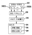
도 5는 본 발명에 따른 블라인드 신호 분리 처리에 대해 신호의 부가적인 합산을 제공하기 위해 확산 코드에 기초하여 동작하는 MIMO 수신기의 블록도이다. 5 is a block diagram of a MIMO receiver operating based on a spreading code to provide additional summation of signals for blind signal separation processing in accordance with the present invention.
도 6은 본 발명에 따른 블라인드 신호 분리 처리에 대해 신호의 부가적인 합산을 제공하기 위해 동상 신호 성분 및 직교 위상 신호 성분에 기초하여 동작하는 MIMO 수신기의 블록도이다.6 is a block diagram of a MIMO receiver operating based on in-phase signal components and quadrature phase signal components to provide additional summation of the signals for blind signal separation processing in accordance with the present invention.
이제, 본 발명은 이하에서 본 발명의 바람직한 실시예들을 도시한 첨부 도면을 참조하여 보다 완전하게 설명될 것이다. 그러나, 본 발명은 많은 다른 형태로 실시될 수도 있고, 여기에 기술된 실시예들에 한정되는 것으로 이해해서는 안된다. 오히려, 이러한 실시예들은 본 발명이 철저하고 완전하게 되도록 제공되며, 당업자에게 본 발명의 범위를 완전하게 전달할 것이다. 동일한 참조 번호는 도면에 걸쳐 동일한 소자들을 나타낸다.The invention will now be described more fully hereinafter with reference to the accompanying drawings, in which preferred embodiments of the invention are shown. However, the invention may be embodied in many other forms and should not be construed as limited to the embodiments set forth herein. Rather, these embodiments are provided so that this invention will be thorough and complete, and will fully convey the scope of the invention to those skilled in the art. Like numbers refer to like elements throughout the drawings.
먼저, 도 1을 참조하여, MIMO 통신 시스템(20)을 설명할 것이다. MIMO 통신 시스템(20)은 송신기(30), 송신 안테나 어레이(32), 수신기(40), 및 수신 안테나 어레이(42)를 포함한다. 당업자라면 용이하게 알 수 있는 바와 같이, 송신기(30)와 수신기(40)는 트랜시버로 대체될 수 있다. 따라서, 이들 각각의 안테나 어레이들(32, 42)은 양방향 데이터 교환을 지원한다. 그러나, 본 발명을 설명하기 위해서, 송신기(30)와 수신기(40)를 참조할 것이다.First, the
송신 안테나 어레이(32)는 M개의 소스 신호들[34(1)-34(M)]을 송신하는 M개의 안테나 소자들[33(1)-33(M)]을 포함한다. 예를 들어, 안테나 소자들[33(1)-33(M)]은 공간적으로 상관화될 수 있다. 소스 신호들[34(1)-34(M)]은 일반적으로 참조 번호 34로 참조되고, 안테나 소자들[33(1)-33(M)]은 일반적으로 참조 번호 33으로 참조될 수 있다. The transmit
수신 안테나 어레이(42)는 M개의 소스 신호들의 M개 이상의 상이한 합산을 수신하는 N개의 안테나 소자들[43(1)-43(N)]을 포함하고, N는 M 미만이다. N < M이기 때문에, 콤팩트한 안테나 어레이가 수신기(40)에 이용되는 동안, 이후에 보다 상세히 설명될 것처럼, 여전히 강력한 MIMO 통신 시스템(20)을 획득할 수 있다. 안테나 소자들[43(1)-43(N)]은 일반적으로 참조 번호 43으로 참조될 수 있다. Receive
다중 경로가 많은 환경에서 다양한 산란 물체들(빌딩들, 차들, 언덕들 등)의 존재로 인해, 각 신호들이 다중 경로 전파를 경험하는 것과 같은 환경에서 각각의 안테나 어레이들(32, 42)이 사용된다. 각각의 경로는 상이한 통신 채널로서 간주될 수 있다. 그래서, 도 1의 참조 번호 50은 송신 안테나 어레이(32)와 수신 안테나 어레이(42) 사이의 다중 경로 채널을 초래하는 산란 환경을 나타낸다. 데이터는 당업계에 공지된 바와 같은 시공간 부호화(STC; space-time coding) 송신 방법을 이용하여 송신 안테나 어레이(32)로부터 송신된다. Due to the presence of various scattering objects (buildings, cars, hills, etc.) in a multipath environment, each
M개의 소스 신호들 이외에, 간섭자(37)로부터의 L개의 간섭 소스 신호들(35)이 산란 환경(50) 내에 존재하여, 원하는 소스 신호들의 분리를 방해한다. 바람직하게, 혼합 행렬을 증가시키는 다양한 수단들이 이후에 보다 상세히 설명될 것처 럼, 계수 M 이상의 혼합 행렬을 채우는데 이용될 수 있다. In addition to the M source signals, L interfering source signals 35 from the
수신 안테나 어레이(42)가 M개의 소스 신호들(34)의 M개의 상이한 합산을 포착하면 신호 처리 기술이 적용되어 그 신호들을 분리한다. 블라인드 신호 분리(BSS) 처리기(44)가 수신기(40)에 연결되어 혼합 행렬이 적어도 M과 동일한 계수를 갖도록 M개의 소스 신호들의 M개 이상의 상이한 합산을 포함하는 혼합 행렬(46)을 형성한다. 블라인드 신호 분리 처리기(44)는 혼합 행렬(46)로부터 원하는 소스 신호들을 분리한다. If receive
본 출원에 보다 상세하게 설명된 바와 같이, 블라인드 신호 분리 기술에 속해 있는 3가지 공통 기술은 주성분 분석(PCA), 독립 성분 분석(ICA), 및 및 고유치 분해(SVD)이다. 신호가 일부 측정할 수 있는 특성에 독립적인 한, 그리고 이들 신호의 합들이 서로에 대해 선형 독립적이면, 하나 이상의 이러한 블라인드 신호 분리 기술들은 소스 신호들의 혼합으로부터 독립적인 소스 신호 또는 원하는 소스 신호들을 분리하는데 이용될 수 있다. 측정할 수 있는 특성은 대개 신호들의 제1, 제2, 제3 또는 제4 모멘트의 일부 조합이다. As described in more detail in this application, three common techniques belonging to blind signal separation techniques are principal component analysis (PCA), independent component analysis (ICA), and eigenvalue decomposition (SVD). As long as the signal is independent of some measurable characteristic, and if the sum of these signals is linearly independent of each other, one or more of these blind signal separation techniques are used to separate the independent source signal or desired source signals from the mix of source signals. Can be used. The measurable characteristic is usually some combination of the first, second, third or fourth moments of the signals.
PCA는 신호를 백색화하고, 제1 모멘트 및 제2 모멘트를 이용하며, 상관 특성에 기초하여 데이터 세트를 회전한다. 소스 신호들의 신호 대 잡음 비가 높은 경우, 신호 분리 프로세스는 PCA로 중단할 수 있다. The PCA whitens the signal, uses the first and second moments, and rotates the data set based on the correlation characteristics. If the signal-to-noise ratio of the source signals is high, the signal separation process can stop with PCA.
소스 신호들의 신호 대 잡음 비가 낮다면, ICA는 소스 신호의 제3 모멘트 및 제4 모멘트를 수반하는 통계적 속성에 기초하여 소스 신호들을 분리한다. 일부 소스 신호들은 정규 분포이며, 이들의 제3 모멘트 및 제4 모멘트는 제1 모멘트 및 제 2 모멘트에 의존한다. 랜덤 노이즈 소스는 정규 분포일 수 있으며, 확산 스펙트럼 신호들은 그들의 특정 확산 코드 이외의 확산 코드에 의해 디코더에 정규 분포를 나타내도록 설계된다. 특정 조건하에서, 전체 신호는 중심 극한 정리(central limit theorem)로 인해 정규 분포를 나타낼 수 있다. ICA 방식은 하나의 정규 분포 신호를 분리할 수 있다. ICA 및 PCA와는 다른 방법으로, SVD는 혼합 소스 신호들의 고유치(eigenvalue)에 기초하여 혼합 소스 신호들로부터 소스 신호들을 분리한다.If the signal-to-noise ratio of the source signals is low, ICA separates the source signals based on the statistical properties accompanying the third and fourth moments of the source signal. Some source signals are normally distributed and their third and fourth moments depend on the first and second moments. The random noise source may be a normal distribution and spread spectrum signals are designed to exhibit a normal distribution to the decoder by spreading codes other than their specific spreading code. Under certain conditions, the overall signal may exhibit a normal distribution due to the central limit theorem. The ICA scheme can separate one normal distribution signal. In a different way from ICA and PCA, SVD separates source signals from mixed source signals based on eigenvalues of the mixed source signals.
블라인드 신호 분리 처리기의 대안으로서, 신호 분리 처리기를 이용하여 정보 기반 처리 신호 추출 프로세스에 기초하여 혼합 행렬로부터 원하는 소스 신호들을 분리할 수 있다. 정보 기반 신호 분리(추출) 프로세스는 예컨대 ZF(zero forcing) 프로세스, 및 MMSE(minimum mean squared estimation) 프로세스 중 적어도 하나에 기초하여 혼합 행렬로부터 원하는 소스 신호를 분리한다. As an alternative to the blind signal separation processor, a signal separation processor may be used to separate the desired source signals from the mixing matrix based on the information based processing signal extraction process. The information based signal separation (extraction) process separates a desired source signal from the mixing matrix based on at least one of, for example, a zero forcing (ZF) process and a minimum mean squared estimation (MMSE) process.
MIMO 통신 시스템(20)의 수신측 상의 상이한 소자들은 도 2를 참조하여 보다 상세하게 설명될 것이다. 수신 안테나 어레이(42)는 M개의 소스 신호들(34)의 M개 이상의 상이한 합산을 수신하는 N개의 안테나 소자들[43(1)-43(N)]을 포함하고, N과 M은 1보다 크고, N는 M 미만이다. 수신 안테나 어레이(42)는 임의의 특정 구성으로 한정되지 않는다. 수신 안테나 어레이(42)는 하나 이상의 안테나 소자들(43)을 포함할 수 있다. 안테나 소자들(43)은, 예컨대 안테나 어레이가 위상 어레이 또는 스위치형 빔 안테나를 형성하도록 구성될 수도 있다.Different elements on the receiving side of the
혼합 행렬(46)을 만들기 위해, 신호의 상이한 합을 생성하는 것을 목표로 한다. 실제로, 이 애플리케이션에서 관심 신호는 간섭자보다 항상 낮을 수 있고, 여 전히 분리될 수 있다. 목적에서 이러한 상당한 차이 때문에, 안테나 소자들(43) 간의 거리는 일반적으로 능동 빔 형성 안테나 어레이와 수동 빔 형성 안테나 어레이로 요구되는 바와 같이 특정하게 분리될 필요가 없다.To make the mixing
수신기(40)는 M개의 소스 신호들(34)의 M개 이상의 상이한 합산을 수신하는 수신 안테나 어레이(42)에 하류측에 연결된다. 블라인드 신호 분리 처리기(44)는 수신기(40)에 하류측에 연결된다. 블라인드 신호 분리 처리기(44)가 수신기(40)와 분리된 것으로 도시되어 있지만, 블라인드 신호 분리 처리기는 또한 수신기 내에 포함될 수도 있다. 수신기(40)에 의해 수신된 M개의 소스 신호들(34)의 상이한 합산은 혼합 행렬(46)을 채우는데 이용된다. 그러면, 혼합 행렬(46)은 블라인드 신호 분리 처리기(44) 내에 있는 하나 이상의 블라인드 신호 분리 처리 모듈들(62, 64, 66)에 의해 처리된다.
블라인드 신호 분리 처리 모듈들은 PCA 모듈(62), ICA 모듈(64), 및 SVD 모듈(66)을 포함한다. 이 모듈들(62, 64, 66)은 블라인드 신호 분리 처리기(44)의 일부분으로서 구성될 수도 있다. PCA 모듈(62)이 수신된 소스 신호들의 상이한 합산의 제1 및 제2 모멘트에 기초하여 동작하는 반면, ICA 모듈(64)은 동일한 신호들의 제3 및 제4 모멘트에 기초하여 동작한다. SVD 모듈(66)은 수신된 소스 신호들의 상이한 합산의 고유치에 기초하여 신호 분리를 수행한다.The blind signal separation processing modules include a
PCA 모듈(62)에 의해 초기에 수행되는 상관 처리가 소스 신호들의 상이한 합산에 대한 초기 분리 행렬[68(1)]을 결정하면, ICA 모듈(64)은 혼합 행렬(46)에서 소스 신호들을 분리하는 개선된 분리 행렬[68(2)]을 결정한다. 신호들이 SVD 모 듈(66)에 의해 분리되면, 혼합 행렬(46)에서 수신된 소스 신호들의 상이한 합산을 분리하는 분리 행렬[68(3)]이 또한 결정된다.If the correlation processing initially performed by the
각각의 분리 행렬[68(1)-68(3)]로부터 분리된 신호들은 참조 번호 49로 나타낸다. 그 후, 분리 신호(49)는 어떤 신호가 관심 신호이고 어떤 신호가 간섭 신호인지를 결정하기 위해 신호 분석 모듈(70)에 의한 신호 분석을 겪게 된다. 애플리케이션 의존 처리 모듈(72)이 신호 분석 모듈(70)로부터의 신호 출력을 처리한다. Signals separated from each separation matrix 68 (1) -68 (3) are indicated by
어떤 신호가 관심 신호인지에 대한 결정은 디코딩될 최종 신호를 항상 수반하는 것은 아니다. 예를 들어, 애플리케이션은 간섭자들을 식별하고 수신된 소스 신호들의 상이한 합산으로부터 그 간섭자들을 차감하여, 파형 디코더에 감소된 신호를 제공하도록 요청할 수 있다. 이 경우에, 관심 신호는 마지막으로 거부되는 것으로 끝나는 신호이다. The determination of which signal is the signal of interest is not always accompanied by the final signal to be decoded. For example, the application may identify the interferers and subtract those interferers from the different summations of the received source signals, asking the waveform decoder to provide the reduced signal. In this case, the signal of interest is the signal that ends with the last rejection.
혼합 행렬(46)의 계수는 얼마나 많은 신호들이 실제로 분리될 수 있는가를 결정한다. 예컨대, 계수 4를 갖는 혼합 행렬은 4개의 소스 신호들이 분리될 수 있음을 의미한다. 이상적으로, 혼합 행렬(46)의 계수는 적어도 소스 신호들의 수(M)와 동일해야 한다. 계수가 클수록, 보다 많은 신호들이 분리될 수 있다. 소스 신호의 수(M)가 증가함에 따라, 요구되는 안테나 소자의 수(N)도 증가한다. 배경 기술에서 설명된 미국 특허 번호 제6,870,515호는 수신기의 안테나 소자의 수(N)는 송신기의 안테나 소자의 수(M) 보다 크거나 같음을 개시한다(즉, N≥M). The coefficient of the mixing
바람직하게, 수신 안테나 어레이(42)는 N개의 안테나 소자들(33)을 이용하여 M개의 소스 신호들(34)의 M개의 상이한 합산을 수신하며, 여기서 N < M 이다. N개 의 안테나 소자들(43)은 M개의 소스 신호들의 M개의 상이한 합산을 수신하는 M개 이상의 상이한 안테나 패턴을 생성한다. 수신 안테나 어레이(42)에서 N개의 안테나 소자들(43)에 의해 수신된 M개의 소스 신호들(34)의 M개의 상이한 합산은 혼합 행렬(46)을 채우는데 이용되어 그 혼합 행렬이 적어도 M과 동일한 계수를 갖도록 한다.Preferably, receive
전술한 바와 같이, 혼합 행렬(46)의 계수는 얼마나 많은 신호들이 실제로 분리될 수 있는가를 결정한다. 계수가 클수록, 보다 많은 신호들이 분리될 수 있다. 따라서, 송신 안테나 어레이(32)의 M개의 안테나 소자들(33)보다 적은 N개의 안테나 소자들(43)을 갖는 콤팩트한 수신 안테나 어레이(42)는 MIMO 수신기(40)에 의해 이용될 수 있으면서 여전히 강력한 MIMO 통신 시스템(20)을 제공할 수 있다.As mentioned above, the coefficients of the mixing
M개의 선형 독립적 합산이 M개의 송신 안테나 소자들(34)의 완전한 MIMO 구현을 지원하기 위해 필요한 최소한의 것이지만, M을 초과하는 것에 이점이 있다. 예를 들어, 수신 안테나 어레이(42)에서의 N개의 안테나 소자들(43) 모두가 M개의 선형 독립적 합산을 수신하도록 방향 지어지는 것은 아니다. 마찬가지로, 수신된 합산 모두가 충분히 선형 독립적이지 않다. 분리될 M개의 알려진 신호 스트림이외에, 신호 대 잡음 비를 악화시키는 L개의 다른 신호들이 또한 있을 수 있다.M linearly independent summation is the minimum necessary to support a full MIMO implementation of M transmit
따라서, 가능한 경우 M+L로 혼합 행렬의 계수를 증가시키는 이점을 취하는 것이 바람직하다. 간섭 또는 노이즈 소스를 분리시키는 것의 다른 이점은 결과적으로 신호 대 잡음 비가 결과적으로 줄어들어, 데이터 전송률을 높이고, 에러율을 낮추고 및/또는 송신 전력을 감소시키는 것이 가능하다. Therefore, it is desirable to take advantage of increasing the coefficients of the mixing matrix by M + L where possible. Another advantage of isolating interference or noise sources is that the signal-to-noise ratio is consequently reduced as a result, which makes it possible to increase the data rate, lower the error rate and / or reduce the transmit power.
예컨대, 혼합 행렬로부터 원하는 소스 신호들(34)의 분리를 방해하는 L개의 간섭 소스 신호들(35)이 존재할 수 있으며, 여기서 L은 1보다 크다. 혼합 행렬의 계수를 증가시키는 것이 부가적인 안테나 소자들을 추가해야만 하는 것 없이 소진된다면, 하나 이상의 부가적인 안테나 소자를 추가하는 것은 부가적인 수단을 제공하여 혼합 행렬의 계수를 증가시킬 것이다. 부가적인 소자들을 추가하는 것은 종래의 MIMO 방식의 M개 미만의 소자들의 수를 고수하지 않을 수 있고, 또는 소자들의 수를 M개로 되돌리거나, 또는 소자들의 수를 M 이상으로 증가시킬 수도 있다. 혼합 행렬 계수를 증가시킴으로써 획득된 이득에 따라, 부가적인 소자들을 추가하는 것이 수신기 안테나 소자의 수를 증가시키더라도, 여전히 가치가 있다. 예컨대, M개의 소자를 요구하는 M+L 계수의 혼합 행렬은 대개 종래의 처리 방식의 MIMO 수신기를 이용한 M개의 소자 구현보다 우수한 구현이다. 그러나, 본 발명을 설명하기 위해, 이하 논의는 M개의 소스 신호들에 초점을 맞출 것이다. For example, there may be L interference source signals 35 that interfere with the separation of the desired source signals 34 from the mixing matrix, where L is greater than one. If increasing the coefficient of the mixing matrix is exhausted without having to add additional antenna elements, adding one or more additional antenna elements will provide additional means to increase the coefficient of the mixing matrix. Adding additional elements may not adhere to the number of elements less than M of conventional MIMO schemes, or may return the number of elements to M, or increase the number of elements to M or more. Depending on the gain obtained by increasing the mixing matrix coefficients, adding additional elements is still valuable, although increasing the number of receiver antenna elements. For example, a mixing matrix of M + L coefficients requiring M elements is usually an implementation superior to M element implementations using conventional processing MIMO receivers. However, to illustrate the present invention, the following discussion will focus on the M source signals.
수신 안테나 어레이(42)의 다수의 상이한 실시예들이 있다. N개의 안테나 소자들(43)이 상관화되어 위상 어레이를 형성한다. 다른 실시예에서, N개의 상관 안테나 소자들(43)은 스위치형 빔 안테나를 형성하기 위하여 하나 이상의 능동 안테나 소자와 N-1개 까지의 수동 안테나 소자를 포함할 수 있다. 게다가, N개의 상관 안테나 소자들 중 적어도 2개는 상이한 편파를 가질 수 있다.There are a number of different embodiments of receive
수신 안테나 어레이(42)에 대한 다른 실시예들은 M개의 소스 신호들의 수신된 M개의 상이한 합산에서 승수 효과를 가질 수 있다. 바람직하게, 이것은 수신 안테나 어레이(42)에서 N개의 안테나 소자들(43)의 수를 증가시켜야만 하는 것 없이 혼합 행렬(46)의 계수가 추가로 증가될 수 있게 한다. 혼합 행렬(46)의 계수를 증가시킴으로써, 보다 많은 신호들이 블라인드 신호 분리 처리기(44)에 의해 분리될 수 있다. Other embodiments for receive
M개의 소스 신호들(34)의 수신된 M개의 상이한 합산의 수에서의 승수 효과는 이하의 것 중 하나 또는 이하의 조합을 이용하여 달성될 수 있다. 어레이 편향은 소스 신호들(34)의 부가적인 합산을 수신하기 위해 안테나 패턴의 고도 변경을 수반한다. 혼합 행렬(46)을 채우는데 이용되는 소스 신호들(34)의 모든 합산이 상관화되고 및/또는 통계적으로 독립되도록 경로 선택이 수행될 수 있다. 또한, 혼합 행렬(46)을 추가로 채우기 위해 신호 분할이 이용될 수도 있다. 상이한 합산 신호들은 확산 코드를 이용하여 분할될 수 있거나, 또는 동상(I) 성분 및 직교 위상(Q) 성분으로 분할될 수도 있다.The multiplier effect on the number of received M different summations of the M source signals 34 may be achieved using one or a combination of the following. Array deflection involves varying the height of the antenna pattern to receive additional summation of the source signals 34. Path selection may be performed such that all summations of the source signals 34 used to populate the mixing
수신 안테나 어레이에 대한 상이한 실시예들이 이제 도 3 내지 도 6을 참조하여 보다 상세하게 설명될 것이다. 이제, 도 3을 참조하여 어레이 편향이 논의될 것이다. 수신 안테나 어레이(142)는 M개의 소스 신호들의 N개의 상이한 합산을 수신하기 위해 N개의 초기 안테나 패턴들을 발생시키기 위하여 N개의 안테나 소자들(143)을 포함한다. 수신 안테나 어레이(142)는 또한 하나 이상의 부가적인 안테나 패턴을 발생시켜 그것에 의해 M개의 소스 신호들의 하나 이상의 부가적인 상이한 합산을 수신하도록, N개의 초기 안테나 패턴들 중 하나 이상의 고도를 선택적으로 변경하기 위한 고도 제어기(141)를 포함한다.Different embodiments for the receive antenna array will now be described in more detail with reference to FIGS. 3 to 6. Array deflection will now be discussed with reference to FIG. 3. Receive
수신기(140)가 수신 안테나 어레이(142)에 연결되고, N개의 초기 안테나 패 턴들을 이용하여 M개의 소스 신호들의 N개의 상이한 합산을 수신하고, 또한 하나 이상의 부가적인 안테나 패턴을 이용하여 M개의 소스 신호들의 하나 이상의 부가적인 상이한 합산을 수신한다.
블라인드 신호 분리 처리기(144)가 수신기(140)에 연결되어, M개의 소스 신호들의 N개의 상이한 합산 및 M개의 소스 신호들의 하나 이상의 부가적인 상이한 합산을 포함하는 혼합 행렬(146)을 형성한다. 혼합 행렬은 부가적인 안테나 패턴들을 이용하여 수신된 M개의 소스 신호들의 부가적인 상이한 합산의 수와 N을 더한 것과 동일한 계수를 갖는다. 혼합 행렬(146)의 결과 계수는 적어도 M과 동일하다. 블라인드 신호 분리 처리기(144)는 혼합 행렬(146)로부터 원하는 신호를 분리한다.A blind signal separation processor 144 is coupled to the
일반적으로, 혼합 행렬의 계수를 증가시키는데 적합한 신호 합을 제공하는 임의의 안테나 어레이 수단들이 편향 메커니즘에 이용될 수도 있다. 이 편향은 안테나 어레이 수단 각각에 대한 신호 합들을 이용할 수 있는 2개의 별개의 혼합 행렬을 생성할 것이다. 그러므로, 이 기술의 활용에 의해 2배의 승수 효과를 얻는다.In general, any antenna array means may be used in the deflection mechanism that provides a signal sum suitable for increasing the coefficient of the mixing matrix. This deflection will produce two separate mixing matrices that can utilize the signal sums for each antenna array means. Therefore, the double multiplier effect is obtained by utilizing this technique.
어레이 편향은 안테나와 관련된 K개의 개별 영역으로 분할되고, K개의 영역 각각은 2개의 독립 편향 영역을 제공할 수 있고, 혼합 행렬에 입력된다. 예를 들어, 안테나 어레이가 스스로 N개의 합산을 제공할 수 있고, K개의 개별 편향 영역이 있다면, 혼합 행렬에서 신호 합의 수는 2NK일 수 있다. Array deflection is divided into K separate regions associated with the antenna, each of the K regions may provide two independent deflection regions, and is input to the mixing matrix. For example, if the antenna array can provide N sums by itself and there are K separate deflection regions, the number of signal sums in the mixing matrix can be 2NK.
경로 선택에 기초하여 M개의 신호 소스들에 의해 제공된 소스 신호들을 분리하는 것을 도 4를 참조하여 설명할 것이다. 수신 안테나 어레이(242)는 M개의 소스 신호들의 N개 이상의 상이한 합산을 수신하는 N개 이상의 안테나 빔을 형성하기 위 한 N개의 소자들(243)을 포함하며, N과 M은 2보다 크다. Separating the source signals provided by the M signal sources based on the path selection will be described with reference to FIG. 4. Receive
제어기(250)가 안테나 어레이(242)에 연결되어 N개 이상의 안테나 빔들을 선택적으로 형성한다. 수신기 어셈블리(240)가 안테나 어레이(242)에 연결되어 M개의 소스 신호들의 N개 이상의 상이한 합산을 수신한다. 블라인드 신호 분리 처리기(244)가 수신기 어셈블리(240)에 연결되어 M개의 소스 신호들의 적어도 N개 까지의 상이한 합산을 포함하는 혼합 행렬(246)을 형성한다.
블라인드 신호 분리 처리기(244)는 또한 M개의 소스 신호들의 상이한 합산이 상관화되어 있는지 또는 통계적으로 독립되어 있는지를 결정하고, 만약 그렇지 않다면, 혼합 행렬(246)에서 상관화되지 않거나 통계적으로 독립적이지 않은 M개의 소스 신호들의 상이한 합산을 대체하기 위해서, 제어기(250)와 협력하여 M개의 소스 신호들의 새로운 상이한 합산을 수신하는 상이한 빔을 형성한다. 그 결과, 소스 신호들의 M개 이상의 상이한 합산들은 혼합 행렬이 적어도 M과 동일한 계수를 갖도록 수신된다. 그러면, 원하는 소스 신호들은 혼합 행렬(246)로부터 분리된다. The blind
레이크 수신기(rake receiver)는 다중 경로 페이딩의 영향에 대항하도록 설계된 무선 수신기이다. 이것은 개개의 다중 경로 성분을 수신하기 위해서 각각 약간씩 지연된 몇 개의 독립적인 수신기를 이용하여 행해진다. 이것은 대부분의 종류의 무선 액세스 네트워크에 의해 이용될 수 있다. 이것은 확산 코드 형태의 변조에 특히 유익한 것으로 발견되었다. 특정한 입사 신호 경로를 선택하는 능력은 블라인드 신호 분리 처리기(244)에 공급되는 경로들을 변경하기 위한 수단으로서 적합하다.A rake receiver is a wireless receiver designed to counter the effects of multipath fading. This is done using several independent receivers, each delayed slightly to receive individual multipath components. This can be used by most kinds of radio access networks. This has been found to be particularly beneficial for modulation in the form of spreading codes. The ability to select a particular incident signal path is suitable as a means for changing the paths supplied to the blind
전술한 바와 같이 N개의 안테나 빔들을 선택적으로 형성하는 것은 당업자에 의해 용이하게 이해되는 바처럼 모든 무선 액세스 네트워크들에 적용될 수 있다. CDMA 시스템의 경우, 수신기 어셈블리(240)는 N개의 레이크 수신기들(256)을 포함한다. 각각의 레이크 수신기(256)는 k개의 핑거(finger)를 포함하여 그것에 연결된 각각의 안테나 소자에 의해 수신된 M개의 소스 신호들의 N개의 상이한 합산들 각각에 대해 k개의 상이한 다중 경로 성분을 선택한다. 이 구성에서, 블라인드 신호 분리 처리기(244)는 N개의 레이크 수신기들(256)에 연결되어 혼합 행렬(246)을 형성한다. 혼합 행렬(246)은 M개의 소스 신호들의 N개 이상의 상이한 합산의 적어도 kN개 까지의 상이한 다중 경로 성분만큼을 포함하고, 혼합 행렬은 최대 kN과 동일한 계수를 갖고, 여기서 kN은 적어도 M과 동일하다. Selectively forming the N antenna beams as described above can be applied to all radio access networks as will be readily understood by those skilled in the art. In the case of a CDMA system,
특히, CDMA 파형들이 전파되는 경우, CDMA 파형들은 대개 소스부터 목적지까지 다중 경로들과 마주친다. 레이크 수신기(256)는 다수의 이러한 개별 사례들을 포착하고, 보다 강력한 신호 디코딩을 위해 이들을 결합하도록 특정하게 설계된다. 원천 신호들이 각각의 경로를 따라 전파되는 동안, 신호의 특성은 경로의 고유 특성으로 인해 변형된다. 일부 상황에서, 수신된 신호의 상관 관계 및/또는 통계적 속성에 대한 변형은, 이들이 분리할 수 있는 신호 스트림으로서 처리될 수 있을 정도로 매우 클 수 있다. 변형된 레이크 수신기(256)는 각각의 변형된 스트림을 추출하는데 이용되어, 그것을 혼합 행렬(246)에 고유한 입력으로서 공급할 수 있다. 계수를 증가시키는 이 수단이 항상 이용가능한 것은 아니지만, 이것이 아마도 필요한 경우에 높은 다중 경로 환경에서 이용가능하게 되기 쉽다.In particular, when CDMA waveforms are propagated, CDMA waveforms usually encounter multiple paths from source to destination.
레이크 수신기(256)가 상이한 경로들을 이용할 수 있지만, 임의의 변조 기술에 적용가능한 보다 일반적인 방식은 빔 형성이다. 빔 형성이 원하는 신호의 개선은 물론 원하는 신호의 거절에도 이용되기 때문에 이것은 레이크 수신기(256)와는 다르다. 그러나, 그 차이는 거절된 신호가 실질적으로는 수신기를 향하는 신호의 다른 버전일 수도 있다는 것이다. 그러나, 수신기 어셈블리(240)는 혼합 행렬(246)을 충분한 계수로 만들기 위해서 동일 신호의 다수의 고유한 전파 경로 버전들을 검출할 필요가 있다. Although
또한, 혼합 행렬(A)을 추가로 채우기 위해 신호 분할(signal splitting)이 이용될 수도 있다. 일 방식에서, 합산 신호들은 확산 코드를 이용하여 분할된다. 다른 방식에서, 합산 신호들은 동상(I) 성분 및 직교 위상(Q) 성분 모듈을 이용하여 분할된다.In addition, signal splitting may be used to further fill the mixing matrix A. FIG. In one scheme, the summation signals are split using a spreading code. In another way, the summation signals are split using in-phase (I) component and quadrature (Q) component module.
이제, 확산 코드를 이용하는 신호 분할을 도 5를 참조하여 설명할 것이다. 수신 안테나 어레이(342)는 M개의 소스 신호들의 N개 이상의 상이한 합산을 수신하기 위하여 N개의 안테나 소자들(343)을 포함한다. 코드 역확산기(350)가 N개의 안테나 소자들(343)에 연결되어 M개의 소스 신호들의 N개 이상의 상이한 합산들을 디코딩한다. N개의 상이한 합산의 각각은 그것과 관련된 M개의 소스 신호들의 k개의 상이한 합산을 제공하는 k개의 코드들을 포함한다. Signal division using spreading code will now be described with reference to FIG. Receive
수신기 어셈블리(340)가 코드 역확산기(350)에 연결되어 M개의 소스 신호들의 kN개 이상의 상이한 합산을 수신한다. 블라인드 신호 분리 처리기(344)가 수신기 어셈블리(340)에 연결되어 M개의 소스 신호들의 kN개 이상의 상이한 합산을 포 함하는 혼합 행렬(346)을 형성한다. 혼합 행렬(346)은 kN 만큼과 동일한 계수를 가지며, 결과 계수는 적어도 M과 동일하다. 블라인드 신호 분리 처리기(344)는 혼합 행렬(346)로부터 원하는 소스 신호들을 분리한다.
수신된 신호의 변조에 따라, 전술한 신호 분할은 N개의 안테나 소자의 수를 증가시킴 없이 혼합 행렬의 계수를 증가시키는데 이용될 수 있다. 확산 코드들이 이용되는 대역 확산 통신 시스템의 예로 CDMA IS-95, CDMA 2000 및 WCDMA가 있다. 공통 쓰레드(common thread)는 보다 넓은 주파수 대역을 통해 데이터를 확산하기 위해 고유 코드를 각각의 신호로 처리하는 것이다. Depending on the modulation of the received signal, the aforementioned signal division can be used to increase the coefficient of the mixing matrix without increasing the number of N antenna elements. Examples of spread spectrum communication systems in which spreading codes are used are CDMA IS-95, CDMA 2000 and WCDMA. A common thread is to process a unique code into each signal to spread data over a wider frequency band.
동일한 확산 코드가 수신된 신호 합(원하는 신호, 원하지 않는 신호 및 미지의 노이즈 소스들)으로 처리된다. 이것은 원하는 신호를 그 원래의 주파수 대역폭으로 다시 재구성하면서, 간섭자는 넓은 주파수 대역으로 확산시킨다. The same spreading code is processed with the received signal sum (desired signal, unwanted signal and unknown noise sources). This reconstructs the desired signal back to its original frequency bandwidth while spreading the interferer over a wide frequency band.
앞서 나열된 CDMA 구현들은 동일한 주파수 대역을 동시에 이용하는 수많은 신호 스트림들을 실제로 갖고 있다. 각각의 신호 스트림은 이상적으로 모든 다른 신호들에 직교하는 코드를 이용한다. 이 조건이 디코더에 부합한다면, 이것은 오직 관심 신호만을 역확산시킨다는 것을 의미한다.The CDMA implementations listed above actually have numerous signal streams using the same frequency band simultaneously. Each signal stream uses a code that is ideally orthogonal to all other signals. If this condition matches the decoder, this means that only the signal of interest is despread.
대개 CDMA 신호들 간에는 일부의 상관 관계가 있어서, 간섭 신호들은 원하는 신호와 함께 어느정도 재구성된다. 이것은 대개 개별 신호들이 경험하는 지연으로 인한 것이고, 또한 신호들의 다중 경로 발생에 의한 것이다. 원하지 않는 신호의 일부, 특히 CDMA 신호의 값이 증가할 것이다. 이 증가는 원하는 신호만큼 중요한 것은 아니지만, 전체 노이즈 값을 증가시켜, 신호 대 잡음 비를 감소시킨다.Usually there is some correlation between the CDMA signals, so that the interfering signals are reconstructed to some extent with the desired signal. This is usually due to the delay experienced by the individual signals and also by the multipath generation of the signals. Some of the unwanted signals, in particular the value of the CDMA signal, will increase. This increase is not as important as the desired signal, but increases the overall noise value, reducing the signal-to-noise ratio.
역확산 신호 수학식의 형태 및 신호 자체가 블라인드 신호 분리 처리의 기준에 부합한다. 실제로, 디스프레딩 코드들 중 하나가 수신기 어셈블리(340)에 의해 수신된 각각의 알려진 신호에 개별적으로 적용되면, ICA 모델 요건에 부합하는 개별 합산을 획득한다.The form of the despread signal equation and the signal itself meet the criteria of blind signal separation processing. Indeed, if one of the despreading codes is individually applied to each known signal received by
그러므로, 알려진 코드로서 혼합 행렬에 이용할 수 있는 수많은 행 엔트리(row entry)들이 있고, 물론 행 엔트리 각각은 선형 독립적인 중요한 값을 생성하는 것으로 가정한다. 정상적인 상황에서, 이것은 코드들의 수보다 큰 값으로 혼합 행렬의 증가를 허용할 것이다. 예컨대, N개의 안테나 소자들과 M개의 코드들은 NM개의 행렬 행을 제공할 수 있다.Therefore, there are a number of row entries that can be used in a mixing matrix as known code, and of course it is assumed that each row entry produces an important value that is linearly independent. Under normal circumstances, this will allow an increase of the mixing matrix to a value greater than the number of codes. For example, N antenna elements and M codes may provide NM matrix rows.
설명을 위해, 3개의 코드들이 알려진 것으로 가정하고, 3개의 알려진 코드 신호들은 자신의 직교성을 유지한다. 코드 역확산기(350)에서, 혼합 행렬(A)은, 각각의 스트림이 3개의 알려진 코드들에 의해 역확산된 후에 안테나 스트림으로 인해 상부에 3개의 행과 하부에 3개의 행을 각각 갖는다. 코드들의 직교성으로 인해 비대각 (off diagonal)의 값은 0이 된다. 열 엔트리(4, 5, 6)는 동일한 인덱스의 미지의 신호들에 대한 일반적인 경우이다. For illustrative purposes, assume three codes are known, and the three known code signals maintain their orthogonality. In

열 엔트리(4, 5, 6)에 대응하는 신호들은 알려진 코드의 다른 경로 버전일 수 있고, 또는 미지의 코드의 다른 셀 신호들일 수 있다. 또한, 하나의 신호는 정규 분포 신호일 수 있고, 다른 신호는 중심 극한 정리를 준수하는 CDMA 신호 그룹의 어느 신호일 수 있어서, 이들은 단일 정규 분포 신호(예컨대, 릴리즈 4 채널들)로서 나타날 수 있다. 다시 말하면, 충분한 양의 랜덤하지 않은 신호들이 정규 분포 신호에 부가될 것이다. 간섭자들은 비정규 분포 신호 소스 또는 네트워크에서 모르는 많아야 하나의 정규 분포 신호일 수 있다.The signals corresponding to column entries 4, 5, 6 may be different path versions of known code, or may be other cell signals of unknown code. In addition, one signal may be a normal distribution signal, and the other signal may be any signal in the CDMA signal group that conforms to the center limit theorem, so that they may appear as a single normal distribution signal (eg, Release 4 channels). In other words, a sufficient amount of non-random signals will be added to the normal distribution signal. The interferers can be at most one normally distributed signal that is unknown to the nonnormally distributed signal source or network.
코드 역확산기(350)에서 알려진 코드들을 디스프레딩한 후에, 블라인드 신호 분리 처리기(344)는 계수 6의 혼합 행렬(346)을 수신한다. 계수 6은 3개의 코드가 알려졌기 때문에 3배로 곱해진 2개의 안테나 소자들에 기초하여 유도된다. After despreading known codes in
6개의 신호들이 블라인드 신호 분리 처리기(344)에 적용되고, 여기서 계수 6을 갖는 혼합 행렬(346)이 형성된다. 블라인드 신호 분리 처리기(344)는 오직 채널에 의해 변경된 수신 신호들(x = As)로부터 분리 행렬(W)을 결정하고, 여기서 A는 혼합 행렬이다. 설명된 예에서, 6개의 신호들이 분리될 수 있다.Six signals are applied to the blind
블라인드 신호 분리 처리기(344)는 디코딩될 신호들을 선택한다. 예컨대, 간섭 신호들은 탈락되고 원하는 신호들의 모든 버전들이 선택될 수 있다. 선택된 신호들은 복조를 위해 복조기 모듈에 적용된다. 복조기는 동일한 신호의 다중 경로 버전을 결합하는 잘 알려진 등화 기법(equalization technique)을 이용한다. The blind
보다 일반적인 경우에, 비대각의 값은 앞에서 간단히 0으로서 나타내었지만, 실질적으로 0이 아닐 수 있다. 이것은 코딩된 신호들 간의 상관 특성이 완전하지 않은 경우 보다 일반적인 경우이다. 이것은 부가적인 노이즈를 각각의 분리된 신호들로 표현한다. 그러나, 앞서 도시한 바와 같이, 행렬의 계수가 이들 신호들을 분리하는데 충분하므로, 비대각의 값은 블라인드 신호 분리 처리 이후에 상당히 감소될 것이다. 이것은 잡음의 감소, 신호 대 잡음 비의 증가, 및 섀넌의 법칙(Shannon' s law)에 나타난 바와 같이 채널 용량의 증가에 이르게 된다. In the more general case, the non-diagonal value is shown simply as 0 above, but may not be substantially zero. This is a more common case where the correlation characteristics between coded signals are not perfect. This expresses additional noise into separate signals. However, as shown above, since the coefficients of the matrix are sufficient to separate these signals, the non-diagonal value will be significantly reduced after the blind signal separation process. This leads to a reduction in noise, an increase in the signal-to-noise ratio, and an increase in channel capacity, as indicated by Shannon's law.
도 6을 참조하면, N개의 안테나 소자의 수를 증가시킴 없이 혼합 행렬(A)의 계수를 증가시키는 다른 방식은 수신된 혼합 신호를 동상(I) 성분 및 직교 위상(Q) 성분으로 분리하는 것이다. 가간섭성 RF 신호(coherent RF signal)의 I 성분 및 Q 성분은 진폭이 동일하지만 위상은 90도 차이나는 성분들이다.Referring to FIG. 6, another way of increasing the coefficient of the mixing matrix A without increasing the number of N antenna elements is to separate the received mixed signal into in-phase (I) and quadrature (Q) components. . The I and Q components of the coherent RF signal are the same in amplitude but 90 degrees out of phase.
수신 안테나 어레이(442)는 M개의 소스 신호들의 N개 이상의 상이한 합산을 수신하기 위하여 N개의 안테나 소자들(443)을 포함한다. 각각의 동상 및 직교 위상 모듈(450)이 각 안테나 소자(443)의 하류에 있어 안테나 소자에 수신된 M개의 소스 신호들의 N개의 상이한 합산을 각각 동상 및 직교 위상 성분 세트로 분리한다. Receive
수신기 어셈블리(440)가 각각의 동상 및 직교 위상 모듈(450)의 하류에 있어 M개의 소스 신호들의 N개 이상의 상이한 합산에 대해 N개 이상의 동상 및 직교 위상 성분 세트를 수신한다. 블라인드 신호 분리 처리기(444)가 수신기 어셈블리(440)의 하류에 있어 M개의 소스 신호들의 2N개 이상의 상이한 합산을 포함하는 혼합 행렬(446)을 형성한다. 각각의 동상 및 직교 위상 성분 세트는 혼합 행렬(446)에 2개의 입력을 제공한다. 혼합 행렬(446)은 2N 만큼과 동일한 계수를 가지며, 블라인드 신호 분리 처리기(444)는 혼합 행렬(512)로부터 원하는 소스 신호 들(514)을 분리한다.
수신된 혼합 신호들을 I 성분 및 Q 성분으로 분리함으로써, 혼합 행렬의 크기는 2배로 증가한다. I 성분 및 Q 성분이 상이한 데이터 스트림들을 이용하여 인코딩되는 한, 임의의 안테나 소자에서 수신된 혼합 신호는 2개의 상이한 혼합 신호들로 분할될 수 있다.By separating the received mixed signals into I and Q components, the size of the mixing matrix is doubled. As long as the I and Q components are encoded using different data streams, the mixed signal received at any antenna element may be divided into two different mixed signals.
차동 인코딩의 경우, 변조의 성격은 I 및 Q가 선형 요건에 부합하는지를 결정하기 위해 분석될 필요가 있다. 예를 들어, GSM의 경우, GMSK 인코딩은 적절한 필터링에 이용되는 경우 선형으로 가정될 수 있고, BPSK 인코딩인 것처럼 수신기에서 처리될 수 있음을 보여준다. BPSK가 블라인드 신호 분리 처리에 대한 요건에 부합하기 때문에, 설명된 I 및 Q 프로세스가 이용될 수 있다.For differential encoding, the nature of the modulation needs to be analyzed to determine whether I and Q meet the linear requirements. For GSM, for example, GMSK encoding can be assumed linear when used for proper filtering and shows that it can be processed at the receiver as if it were BPSK encoding. Since the BPSK meets the requirements for blind signal separation processing, the I and Q processes described can be used.
I 성분 및 Q 성분은 혼합 행렬(A)을 채우기 위해 전술한 안테나 어레이 실시예들 중 임의의 것에 이용할 수 있다. I 및 Q가 이용되는 경우, 2배의 안테나 소자의 수가 이용되는 것처럼 혼합 행렬(A)을 채울 수 있다. 안테나 소자는 비상관, 상관 또는 편파와 같은 임의의 다이버시티 형태일 수 있다. 각 소자들의 신호 합을 I 성분 및 Q 성분으로 분할하는 N개의 안테나 소자들은 2N개의 독립적인 혼합 신호 합을 제공한다. 그 결과, 혼합 행렬의 계수는 2N이고, 여기서 2N은 적어도 M과 동일하거나 M보다 크다. The I component and the Q component can be used in any of the above described antenna array embodiments to populate the mixing matrix (A). When I and Q are used, the mixing matrix A can be filled as if the number of antenna elements is doubled. The antenna element may be in the form of any diversity such as uncorrelated, correlated or polarized. N antenna elements that divide the signal sum of each element into I and Q components provide 2N independent mixed signal sums. As a result, the coefficient of the mixing matrix is 2N, where 2N is at least equal to or greater than M.
또한, 이 메커니즘은 신호의 보다 많은 합을 생성하기 위해 안테나 어레이 편향 기술로도 이용될 수 있다. 또한, 이러한 합의 각각은 차례로 I 성분 및 Q 성분으로 분리될 수 있다. I 및 Q로 인한 2배의 증가, N개의 안테나 소자들, 및 안테 나 어레이에 대한 k개의 편향 영역은 혼합 행렬에 대해 2kN개의 합을 제공한다.This mechanism can also be used as an antenna array deflection technique to generate more sum of signals. In addition, each of these sums may in turn be separated into I and Q components. The doubled increase due to I and Q, the N antenna elements, and the k deflection regions for the antenna array provide 2kN sums for the mixing matrix.
당업자라면 발명의 많은 변경 및 다른 실시예들이 전술한 설명 및 관련 도면에 나타난 기술들의 이점을 갖는다는 것을 이해할 것이다. 그러므로, 본 발명은 개시된 특정 실시예들에 한정되지 않고, 첨부된 청구의 범위 내에 변경 및 다른 실시예들이 포함될 수 있는 것은 당연하다.Those skilled in the art will appreciate that many modifications and other embodiments of the invention will benefit from the techniques presented in the foregoing descriptions and the associated drawings. Therefore, it is to be understood that the invention is not limited to the specific embodiments disclosed and that modifications and other embodiments can be included within the scope of the appended claims.
Claims (25)
Applications Claiming Priority (4)
| Application Number | Priority Date | Filing Date | Title |
|---|---|---|---|
| US11/233,329 US8031117B2 (en) | 2004-09-23 | 2005-09-22 | Blind signal separation using polarized antenna elements |
| US11/233,329 | 2005-09-22 | ||
| US11/326,042 | 2006-01-05 | ||
| US11/326,042 US7627052B2 (en) | 2004-09-23 | 2006-01-05 | Pattern diversity to support a MIMO receiver and associated methods |
Publications (2)
| Publication Number | Publication Date |
|---|---|
| KR20080050626A KR20080050626A (en) | 2008-06-09 |
| KR100936202B1 true KR100936202B1 (en) | 2010-01-11 |
Family
ID=39805837
Family Applications (1)
| Application Number | Title | Priority Date | Filing Date |
|---|---|---|---|
| KR1020087009621A KR100936202B1 (en) | 2005-09-22 | 2006-09-22 | Pattern diversity to support a mimo receiver and associated methods |
Country Status (6)
| Country | Link |
|---|---|
| JP (1) | JP2009510840A (en) |
| KR (1) | KR100936202B1 (en) |
| CN (1) | CN101273278A (en) |
| BR (1) | BRPI0617544A2 (en) |
| IL (1) | IL190368A0 (en) |
| RU (1) | RU2387079C2 (en) |
Families Citing this family (3)
| Publication number | Priority date | Publication date | Assignee | Title |
|---|---|---|---|---|
| CN102215048A (en) * | 2011-07-27 | 2011-10-12 | 中国人民解放军总参谋部第六十三研究所 | Receiving method and receiving device of spread spectrum signals |
| CN104601233B (en) * | 2013-10-30 | 2018-06-12 | 中南大学 | MIMO visible light communication methods based on carrier wave distribution with ICA algorithm |
| CN107948114B (en) * | 2017-11-15 | 2021-02-05 | 桂林电子科技大学 | MIMO blind source signal separation system and signal separation method |
Citations (2)
| Publication number | Priority date | Publication date | Assignee | Title |
|---|---|---|---|---|
| US20040047426A1 (en) * | 2002-09-09 | 2004-03-11 | Nissani Nissensohn Daniel Nathan | Multi input multi output wireless communication method and apparatus providing extended range and extended rate across imperfectly estimated channels |
| US6760388B2 (en) * | 2001-12-07 | 2004-07-06 | Qualcomm Incorporated | Time-domain transmit and receive processing with channel eigen-mode decomposition for MIMO systems |
Family Cites Families (8)
| Publication number | Priority date | Publication date | Assignee | Title |
|---|---|---|---|---|
| US20040032910A1 (en) * | 2002-08-13 | 2004-02-19 | Jyhchau Horng | MIMO systems with STTD encoding and dynamic power allocation |
| US20050259005A1 (en) * | 2004-05-20 | 2005-11-24 | Interdigital Technology Corporation | Beam forming matrix-fed circular array system |
| US7627052B2 (en) * | 2004-09-23 | 2009-12-01 | Interdigital Technology Corporation | Pattern diversity to support a MIMO receiver and associated methods |
| US7113129B2 (en) * | 2004-09-23 | 2006-09-26 | Interdigital Technology Corporation | Blind signal separation using a combination of correlated and uncorrelated antenna elements |
| US8031117B2 (en) * | 2004-09-23 | 2011-10-04 | Interdigital Technology Corporation | Blind signal separation using polarized antenna elements |
| US7190308B2 (en) * | 2004-09-23 | 2007-03-13 | Interdigital Technology Corporation | Blind signal separation using signal path selection |
| US7116271B2 (en) * | 2004-09-23 | 2006-10-03 | Interdigital Technology Corporation | Blind signal separation using spreading codes |
| US7123191B2 (en) * | 2004-09-23 | 2006-10-17 | Interdigital Technology Corporation | Blind signal separation using I and Q components |
-
2006
- 2006-09-22 KR KR1020087009621A patent/KR100936202B1/en not_active IP Right Cessation
- 2006-09-22 CN CNA2006800350329A patent/CN101273278A/en active Pending
- 2006-09-22 BR BRPI0617544-9A patent/BRPI0617544A2/en not_active IP Right Cessation
- 2006-09-22 RU RU2008115506/09A patent/RU2387079C2/en not_active IP Right Cessation
- 2006-09-22 JP JP2008532436A patent/JP2009510840A/en active Pending
-
2008
- 2008-03-23 IL IL190368A patent/IL190368A0/en unknown
Patent Citations (2)
| Publication number | Priority date | Publication date | Assignee | Title |
|---|---|---|---|---|
| US6760388B2 (en) * | 2001-12-07 | 2004-07-06 | Qualcomm Incorporated | Time-domain transmit and receive processing with channel eigen-mode decomposition for MIMO systems |
| US20040047426A1 (en) * | 2002-09-09 | 2004-03-11 | Nissani Nissensohn Daniel Nathan | Multi input multi output wireless communication method and apparatus providing extended range and extended rate across imperfectly estimated channels |
Also Published As
| Publication number | Publication date |
|---|---|
| KR20080050626A (en) | 2008-06-09 |
| RU2387079C2 (en) | 2010-04-20 |
| RU2008115506A (en) | 2009-10-27 |
| IL190368A0 (en) | 2009-09-22 |
| JP2009510840A (en) | 2009-03-12 |
| BRPI0617544A2 (en) | 2011-07-26 |
| CN101273278A (en) | 2008-09-24 |
Similar Documents
| Publication | Publication Date | Title |
|---|---|---|
| KR100904470B1 (en) | Pattern diversity to support a mimo communications system and associated methods | |
| US9923617B2 (en) | Communication channel optimization systems and methods in multi-user communication systems | |
| EP1575188B1 (en) | Apparatus and method for receiving signal in a multiple-input multiple-output communication system | |
| CN101207600B (en) | Method, system and apparatus for MIMO transmission of multi transmitting antennas | |
| KR20050015731A (en) | Method and apparatus for deciding shuffling pattern in double space-time transmit diversity system using minimum signal to noise ratio | |
| AU2006295451A1 (en) | Pattern diversity to support a MIMO receiver and associated methods | |
| US8077758B2 (en) | Signal separation techniques to provide robust spread spectrum signal decoding | |
| KR100936202B1 (en) | Pattern diversity to support a mimo receiver and associated methods | |
| de Figueiredo et al. | Uplink performance evaluation of massive MU-MIMO systems | |
| Mudulodu et al. | A simple multiplexing scheme for MIMO systems using multiple spreading codes | |
| Senaratne et al. | Spatial multipath resolution for MIMO systems | |
| Ng et al. | A novel spread space-spectrum multiple access scheme for the forward link | |
| Zhu et al. | Signalling wavelength in an antenna array for space-time wireless over LOS channels | |
| Alaamer | Enhanced Performance of the MIMO Channel by Using the Beamforming Technique and the Rack Receiver | |
| Chen et al. | Multi-User MIMO Systems Using Semi-Orthogonal Space Division Multiplexing with Alamouti Code | |
| Lundahl | High Branch Transmit Diversity in WCDMA | |
| Melvasalo | Advanced receivers for high data rate mobile communications | |
| Jin et al. | Modified precoding strategy over MIMO double-correlated channels | |
| CN103595452A (en) | Multi-input Multi-output communication system |
Legal Events
| Date | Code | Title | Description |
|---|---|---|---|
| A201 | Request for examination | ||
| PA0105 | International application |
Patent event date: 20080422 Patent event code: PA01051R01D Comment text: International Patent Application |
|
| PA0201 | Request for examination | ||
| PG1501 | Laying open of application | ||
| E701 | Decision to grant or registration of patent right | ||
| PE0701 | Decision of registration |
Patent event code: PE07011S01D Comment text: Decision to Grant Registration Patent event date: 20091029 |
|
| GRNT | Written decision to grant | ||
| PR0701 | Registration of establishment |
Comment text: Registration of Establishment Patent event date: 20100104 Patent event code: PR07011E01D |
|
| PR1002 | Payment of registration fee |
Payment date: 20100105 End annual number: 3 Start annual number: 1 |
|
| PG1601 | Publication of registration | ||
| FPAY | Annual fee payment |
Payment date: 20121220 Year of fee payment: 4 |
|
| PR1001 | Payment of annual fee |
Payment date: 20121220 Start annual number: 4 End annual number: 4 |
|
| FPAY | Annual fee payment |
Payment date: 20131219 Year of fee payment: 5 |
|
| PR1001 | Payment of annual fee |
Payment date: 20131219 Start annual number: 5 End annual number: 5 |
|
| LAPS | Lapse due to unpaid annual fee | ||
| PC1903 | Unpaid annual fee |
Termination category: Default of registration fee Termination date: 20151209 |