KR100891819B1 - Direct sampling wireless receiver and method - Google Patents
Direct sampling wireless receiver and method Download PDFInfo
- Publication number
- KR100891819B1 KR100891819B1 KR1020070049833A KR20070049833A KR100891819B1 KR 100891819 B1 KR100891819 B1 KR 100891819B1 KR 1020070049833 A KR1020070049833 A KR 1020070049833A KR 20070049833 A KR20070049833 A KR 20070049833A KR 100891819 B1 KR100891819 B1 KR 100891819B1
- Authority
- KR
- South Korea
- Prior art keywords
- signal
- frequency
- reference signal
- signals
- digital
- Prior art date
- Legal status (The legal status is an assumption and is not a legal conclusion. Google has not performed a legal analysis and makes no representation as to the accuracy of the status listed.)
- Expired - Fee Related
Links
Images


Classifications
-
- H—ELECTRICITY
- H04—ELECTRIC COMMUNICATION TECHNIQUE
- H04L—TRANSMISSION OF DIGITAL INFORMATION, e.g. TELEGRAPHIC COMMUNICATION
- H04L27/00—Modulated-carrier systems
- H04L27/0014—Carrier regulation
-
- H—ELECTRICITY
- H04—ELECTRIC COMMUNICATION TECHNIQUE
- H04B—TRANSMISSION
- H04B1/00—Details of transmission systems, not covered by a single one of groups H04B3/00 - H04B13/00; Details of transmission systems not characterised by the medium used for transmission
- H04B1/06—Receivers
- H04B1/16—Circuits
-
- H—ELECTRICITY
- H04—ELECTRIC COMMUNICATION TECHNIQUE
- H04B—TRANSMISSION
- H04B1/00—Details of transmission systems, not covered by a single one of groups H04B3/00 - H04B13/00; Details of transmission systems not characterised by the medium used for transmission
- H04B1/06—Receivers
-
- H—ELECTRICITY
- H04—ELECTRIC COMMUNICATION TECHNIQUE
- H04L—TRANSMISSION OF DIGITAL INFORMATION, e.g. TELEGRAPHIC COMMUNICATION
- H04L27/00—Modulated-carrier systems
- H04L27/0014—Carrier regulation
- H04L2027/0024—Carrier regulation at the receiver end
-
- H—ELECTRICITY
- H04—ELECTRIC COMMUNICATION TECHNIQUE
- H04L—TRANSMISSION OF DIGITAL INFORMATION, e.g. TELEGRAPHIC COMMUNICATION
- H04L27/00—Modulated-carrier systems
- H04L27/0014—Carrier regulation
- H04L2027/0044—Control loops for carrier regulation
- H04L2027/0046—Open loops
Landscapes
- Engineering & Computer Science (AREA)
- Computer Networks & Wireless Communication (AREA)
- Signal Processing (AREA)
- Digital Transmission Methods That Use Modulated Carrier Waves (AREA)
Abstract
본 발명은 무선 통신용 수신장치에 있어서 무선 통신용 수신장치에 있어서 반송 주파수 직접 변환 방식을 다이렉트 샘플링 방식의 낮은 샘플링율을 사용하고 멀티 포트 네트워크를 채용하여 비선형성 및 DC 옵셋을 개선한 다이렉트 샘플링 방식 무선 수신장치 및 방법에 관한 것이다.
본 발명은 RF 신호의 주파수 대역 폭에 비례하는 주파수를 갖는 제1 기준신호와, 상기 제1 기준 신호 보다 높은 주파수를 갖는 제2 기준 신호를 제공하는 기준 신호 생성부와, 상기 제1 기준 신호에 따라 상기 RF 신호를 샘플링하는 샘플링부와, 상기 샘플링부로부터의 샘플링된 신호를 상기 제2 기준 신호에 따라 디지털 신호로 변환하는 아날로그-디지털 변환부와, 상기 아날로그-디지털 변환부로부터의 디지털 신호를 복수의 신호로 분배하고, 상기 디지털 신호의 주기에 따라 서로 다른 위상을 갖는 복수의 반송파 신호를 생성하여, 상기 복수의 반송파 신호와 상기 복수의 신호를 각각 가산하여 서로 다른 위상을 갖는 복수의 위상 신호를 출력하는 다중 입출력부를 포함한다.

다이렉트 샘플링, 멀티 포트 네트워크, SDR(sotfware defined radio)
In the present invention, the wireless communication receiver has a direct sampling method using a low sampling rate of a direct sampling method and a multi-port network to improve the nonlinearity and DC offset. An apparatus and method are provided.
The present invention provides a first reference signal having a frequency proportional to a frequency band width of an RF signal, a reference signal generator for providing a second reference signal having a higher frequency than the first reference signal, and a first reference signal. A sampling unit for sampling the RF signal, an analog-digital converter for converting the sampled signal from the sampling unit into a digital signal according to the second reference signal, and a digital signal from the analog-digital converter. A plurality of signal signals are divided into a plurality of signals, and a plurality of carrier signals having different phases are generated according to the period of the digital signal, and the plurality of carrier signals and the plurality of signals are added to each other, thereby providing a plurality of phase signals having different phases. It includes a multiple input and output unit for outputting.
Direct sampling, multi-port networks, software defined radio (SDR)
Description
도 1은 본 발명의 무선 수신장치의 구조.1 is a structure of a wireless receiver of the present invention.
도 2는 본 발명의 무선 수신방법을 나타내는 플로우 챠트.2 is a flow chart showing a wireless receiving method of the present invention.
도 3의 (a) 및 (b)는 무선 수신장치의 샘플링 그래프.3 (a) and 3 (b) are sampling graphs of a wireless receiver.
도 4의 (a) 및 (b)는 무선 수신장치의 I신호 및 Q신호의 분포도.4 (a) and 4 (b) are distribution charts of I and Q signals of a radio receiver.
<도면의 주요 부호에 대한 상세한 설명><Detailed Description of Major Symbols in Drawing>
100...무선 수신장치 110...샘플링부100 ...
120...기준신호 생성부 121...발진기120 ... reference signal generator 121 ... oscillator
122...주파수 체배기 130...아날로그-디지털 변환부122
140...다중입출력부 141...분배기140 ...
142...정현파 발생기 143...위상변환기142 ... Sine
144...가산기 그룹 150...연산부144.Adder
151...제곱기 152...필터151
160...I/Q 신호 생성기160 ... I / Q Signal Generator
본 발명은 무선 수신장치 및 방법에 관한 것으로 보다 상세하게는 무선 통신용 수신장치에 있어서 반송 주파수 직접 변환 방식을 다이렉트 샘플링 방식의 낮은 샘플링율을 사용하고 멀티 포트 네트워크를 채용하여 비선형성 및 DC 옵셋을 개선한 다이렉트 샘플링 방식 무선 수신장치 및 방법에 관한 것이다.The present invention relates to a wireless receiver and a method, and more particularly, to a non-linearity and a DC offset in a wireless communication receiver using a direct sampling method using a low sampling rate and a multi-port network. A direct sampling wireless receiver and method are provided.
최근 들어, 무선 통신 분야의 기술 발달에 따라 다양한 무선 통신 기술이 개발되고 있는 실정이다.In recent years, various wireless communication technologies are being developed according to the development of technology in the wireless communication field.
이러한 무선 통신 기술은 주로 RF(Radio Frequency) 신호를 IF(Intermediate Frequency)로 하향 변환(Down Conversion)하고 이를 다시 기저대역(baseband)신호로 변환하여 원 신호에 담긴 정보를 복원하여 사용하는 방식을 주로 채용하고 있다. The wireless communication technology mainly converts a radio frequency (RF) signal down to an intermediate frequency (IF) and converts it back to a baseband signal to recover information contained in the original signal. I adopt it.
상술한 무선 통신 기술은 IF 하향 변환과 다시 기저대역 변환에 따른 많은 RF 소자가 필요하고 시스템 변경 시 RF 소자 특성 및 구조를 모두 변환해 주어야 하는 단점이 있다. 따라서 IF 하향 변환을 사용하지 않은 반송주파수 직접 변환 방식이 사용되어 왔다. The wireless communication technology described above has a disadvantage in that many RF devices are required according to IF downconversion and baseband conversion, and the RF device characteristics and structure must be converted when the system is changed. Therefore, the carrier frequency direct conversion method without using the IF down conversion has been used.
하지만 이러한 반송 주파수 직접 변환 방식의 경우, 시스템 변경에는 용이하나, 직접 변환에 따른 DC 옵셋(offset)이나 I/Q 신호의 위상불일치(phase mismatch) 부분이 발생하여 성능 열화를 야기시키고, 반송 주파수 직접 변환 방식에 채용되는 회로 전체를 디지털 시스템으로 변환하기 위해서는 반송주파수의 2배 높은 주파수를 사용하여 아날로그 신호를 디지털 신호로 변환해야 한다. However, the carrier frequency direct conversion method is easy to change the system, but a DC offset or a phase mismatch of the I / Q signal occurs due to the direct conversion, causing performance deterioration. In order to convert the entire circuit employed in the conversion method into a digital system, an analog signal is converted into a digital signal using a frequency twice as high as the carrier frequency.
만약, 사용 주파수 대역이 수 GHz에 이를 경우 이를 2배 이상 높은 주파수로 샘플링하기 위해서는 샘플링 처리 속도가 고속인 장치를 사용하여야 하는데 이러한 장치는 고성능의 연산 처리를 요구하여 가격의 높아지고 부피가 커져 경박단소화하고자 하는 무선 통신 장치의 경향에 따라 적용하기 불가능한 문제점이 있다.If the frequency band reaches several GHz, in order to sample the frequency more than twice as high, it is necessary to use a device with a high sampling rate. There is a problem that cannot be applied according to the tendency of the wireless communication device to extinguish.
따라서, 상술한 문제점을 해결하기 위해서는 새로운 샘플링 방식의 무선 통신 장치가 필요한 실정이다. Therefore, in order to solve the above problem, a situation in which a new sampling method of a wireless communication device is required.
상술한 문제점을 해결하기 위해 본 발명의 목적은 무선 통신용 수신장치에 있어서 반송 주파수 직접 변환 방식을 다이렉트 샘플링 방식의 낮은 샘플링율을 사용하고 낮은 샘플링율을 사용하고 멀티 포트 네트워크를 채용하여 비선형성 및 DC 옵셋을 개선한 다이렉트 샘플링 방식 무선 수신 장치 및 방법을 제공하는 것이다.In order to solve the above problems, an object of the present invention is to provide a non-linearity and DC by using a direct sampling method, a low sampling rate, a low sampling rate, and adopting a multi-port network. The present invention provides a direct sampling method and a wireless receiver apparatus with improved offset.
상술한 목적을 달성하기 위해, 본 발명의 무선 수신장치는 사전에 설정된 주파수를 갖는 제1 기준신호와, 상기 제1 기준 신호 보다 높은 주파수를 갖는 제2 기준 신호를 제공하는 기준 신호 생성부와, 상기 제1 기준 신호에 따라 상기 RF 신호를 샘플링하는 샘플링부와, 상기 제2 기준 신호에 따라 상기 샘플링부로부터의 샘플링된 신호를 디지털 신호로 변환하는 아날로그-디지털 변환부와, 상기 아날로그-디지털 변환부로부터의 디지털 신호를 복수의 신호로 분배하고, 상기 디지털 신호의 위상을 쉬프트하여 서로 다른 위상을 갖는 복수의 반송파 신호를 생성하여, 상 기 복수의 반송파 신호와 상기 복수의 신호를 각각 가산하여 서로 다른 위상을 갖는 복수의 위상 신호를 출력하는 다중 입출력부를 포함하는 것을 특징으로 한다.In order to achieve the above object, the wireless receiver of the present invention includes a reference signal generator for providing a first reference signal having a preset frequency, a second reference signal having a higher frequency than the first reference signal; A sampling unit for sampling the RF signal according to the first reference signal, an analog-digital converter for converting the sampled signal from the sampling unit into a digital signal according to the second reference signal, and the analog-digital conversion The digital signal from the negative portion is divided into a plurality of signals, the phase of the digital signal is shifted to generate a plurality of carrier signals having different phases, and the plurality of carrier signals and the plurality of signals are added to each other. And multiple input / output units for outputting a plurality of phase signals having different phases.
본 발명의 일 실시형태에 따르면, 상기 제1 기준 신호는 상기 RF 신호의 주파수 대역 폭에 따라 설정되는 주파수를 가질 수 있다.According to an embodiment of the present invention, the first reference signal may have a frequency set according to the frequency bandwidth of the RF signal.
본 발명의 일 실시형태에 따르면, 상기 제1 기준 신호는 수식
![]()
![]()
![]()

![]()
![]()
![]()
![]()
![]()
본 발명의 일 실시형태에 따르면, 상기 제2 기준 신호는 상기 제1 기준 신호의 주파수 보다 2배 이상 높은 주파수를 가질 수 있다.According to an embodiment of the present invention, the second reference signal may have a frequency two times higher than the frequency of the first reference signal.
본 발명의 일 실시형태에 따르면, 상기 기준 신호 발생부는 상기 제1 기준 신호를 발생하는 발진기와, 상기 발진기로부터의 상기 제1 기준 신호를 주파수 체 배하여 상기 제2 기준 신호를 발생하는 주파수 체배기를 포함할 수 있다.According to an embodiment of the present invention, the reference signal generator includes an oscillator for generating the first reference signal, and a frequency multiplier for generating the second reference signal by frequency multiplying the first reference signal from the oscillator. It may include.
본 발명의 일 실시형태에 따르면, 상기 다중 입출력부는 상기 아날로그-디지털 변환부로부터의 상기 디지털 신호의 주기에 따라 정현파 신호를 발생하는 정현파 발생기와, 상기 디지털 신호를 상기 복수의 신호로 분배하는 분배기와, 상기 정현파 신호의 위상을 서로 다르게 쉬프트시켜 서로 다른 위상을 갖는 복수의 반송파 신호를 생성하는 위상변환기와, 상기 분배기로부터의 복수의 신호와 상기 위상변환기로부터의 복수의 반송파 신호를 각각 가산하는 복수의 가산기를 갖는 가산기 그룹을 포함할 수 있다.According to an embodiment of the present invention, the multiple input / output unit includes a sine wave generator for generating a sine wave signal according to the period of the digital signal from the analog-digital converter, and a divider for distributing the digital signal into the plurality of signals. And a phase shifter for generating a plurality of carrier signals having different phases by shifting the phases of the sinusoidal signals differently, and a plurality of signals added from the splitter and a plurality of carrier signals from the phase shifter, respectively. And an adder group having an adder.
본 발명의 일 실시형태에 따르면, 상기 다중 입출력부로부터의 상기 복수의 위상 신호의 크기를 연산하는 연산부를 더 포함할 수 있다.According to one embodiment of the present invention, a calculation unit for calculating the magnitude of the plurality of phase signals from the multiple input and output unit may be further included.
본 발명의 일 실시형태에 따르면, 상기 연산부로부터의 연산된 신호의 크기에 기초하여 I신호와 Q신호를 생성하는 I/Q 신호 생성부를 더 포함할 수 있다.According to the exemplary embodiment of the present invention, the method may further include an I / Q signal generator which generates an I signal and a Q signal based on the magnitude of the calculated signal from the calculator.
본 발명의 일 실시형태에 따르면, 상기 연산부는 상기 다중 입출력부로부터의 상기 복수의 위상 신호의 크기를 각각 제곱하는 제곱기와, 상기 제곱기로부터의 제곱된 복수의 위상 신호의 노이즈를 각각 제거하는 필터를 포함할 수 있다.According to an embodiment of the present invention, the computing unit is a square that squares the magnitudes of the plurality of phase signals from the multiple input / output units, respectively, and a filter that removes noise of the plurality of squared phase signals from the squarer, respectively. It may include.
본 발명의 일 실시형태에 따르면, 상기 다중 입출력부, 연산부 및 I/Q 신호 생성부는 적어도 하나의 프로그래밍 가능한 IC에 소프트웨어로 구성되는 SDR(Software Defined Radio) 시스템일 수 있다.According to an embodiment of the present invention, the multiple input / output unit, arithmetic unit, and I / Q signal generation unit may be a software defined radio (SDR) system configured with software in at least one programmable IC.
본 발명의 다른 목적을 달성하기 위해, 본 발명의 무선 수신 방법은 사전에 설정된 주파수를 갖는 제1 기준신호에 따라 상기 RF 신호를 샘플링하는 단계와, 상기 제1 기준 신호 보다 높은 주파수를 갖는 제2 기준 신호에 따라 샘플링된 신호를 디지털 신호로 변환하는 단계와, 상기 디지털 신호를 복수의 신호로 분배하고, 상기 디지털 신호의 위상을 쉬프트하여 서로 다른 위상을 갖는 복수의 반송파 신호를 생성하며, 상기 복수의 반송파 신호와 상기 복수의 신호를 각각 가산하여 서로 다른 위상을 갖는 복수의 위상 신호를 생성하는 단계를 포함하는 것을 특징으로 한다.In order to achieve another object of the present invention, the wireless reception method of the present invention comprises the steps of sampling the RF signal according to a first reference signal having a predetermined frequency, and a second having a higher frequency than the first reference signal Converting a sampled signal according to a reference signal into a digital signal, distributing the digital signal into a plurality of signals, shifting a phase of the digital signal to generate a plurality of carrier signals having different phases, And adding the carrier signals and the plurality of signals, respectively, to generate a plurality of phase signals having different phases.
본 발명의 일 실시형태에 따르면, 상기 제1 기준 신호는 상기 RF 신호의 주파수 대역 폭에 따라 설정되는 주파수를 가질 수 있다.According to an embodiment of the present invention, the first reference signal may have a frequency set according to the frequency bandwidth of the RF signal.
본 발명의 일 실시형태에 따르면, 상기 제1 기준 신호는 수식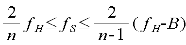
![]()
![]()
![]()

![]()
![]()
![]()
![]()
![]()
본 발명의 일 실시형태에 따르면, 상기 제2 기준 신호는 상기 제1 기준 신호의 주파수 보다 2배 이상 높은 주파수를 가질 수 있다.According to an embodiment of the present invention, the second reference signal may have a frequency two times higher than the frequency of the first reference signal.
본 발명의 일 실시형태에 따르면, 상기 복수의 위상 신호의 크기를 연산하는 단계를 더 포함할 수 있다.According to an embodiment of the present invention, the method may further include calculating magnitudes of the plurality of phase signals.
본 발명의 일 실시형태에 따르면, 상기 복수의 위상 신호의 크기에 기초하여 I신호 및 Q신호를 생성하는 단계를 더 포함할 수 있다.According to an embodiment of the present invention, the method may further include generating an I signal and a Q signal based on the magnitudes of the plurality of phase signals.
본 발명의 일 실시형태에 따르면, 상기 연산하는 단계는 상기 복수의 위상 신호의 크기를 제곱하는 단계와, 제곱된 복수의 위상 신호의 노이즈를 제거하는 단계를 포함할 수 있다.According to an embodiment of the present invention, the calculating may include squaring the magnitudes of the plurality of phase signals, and removing noise of the plurality of squared phase signals.
이하, 도면을 참조하여 본 발명을 상세히 설명하도록 한다.Hereinafter, the present invention will be described in detail with reference to the accompanying drawings.
도 1은 본 발명의 무선 수신 장치의 구성도이다.1 is a block diagram of a wireless receiving apparatus of the present invention.
도 1을 참조하면, 본 발명의 무선 수신 장치(100)는 샘플링부(110)와 기준 신호 생성부(120), 아날로그-디지털 변환부(130) 및 다중 입출력부(140)를 포함한다.Referring to FIG. 1, the
샘플링부(110)는 사전에 설정된 주파수를 갖는 제1 기준 신호에 따라 RF 신호를 샘플링한다. 이때, 상기 RF 신호는 안테나로부터 수신되어 대역 통과된 후 저잡음 증폭되어 샘플링부(110)에 전달될 수 있다. 이에 따라, 샘플링부(110)의 앞단에는 대역 통과 필터(F)와 저잡음 증폭기(P)가 더 포함될 수 있다. 샘플링부(110)는 제1 기순 신호에 따라 상기 RF 신호를 스위칭하여 상기 RF 신호를 샘플링하는 스위치로 형성될 수 있다.The
기준 신호 생성부(120)는 사전에 설정된 주파수를 갖는 제1 기준신호와 상기 제1 기준 신호 보다 높은 주파수를 갖는 제2 기준 신호를 생성한다. 기준 신호 생성부(120)는 상기 제1 기준신호를 제공하는 발진기(121)와 발진기(121)로부터의 상기 제1 기준신호의 주파수를 체배하는 주파수 체배기(122)를 포함할 수 있다. The
상기 제2 기준 신호는 아날로그-디지털 변환부(130)에 전달된다.The second reference signal is transmitted to the analog-
아날로그-디지털 변환부(130)는 상기 제2 기준 신호에 따라 샘플링부(110)로 부터의 샘플링된 신호를 디지털 신호로 변환한다. 변환된 디지털 신호는 다중 입출력부(140)로 전달된다.The analog-
다중 입출력부(140)는 아날로그-디지털 변환부(130)로부터의 상기 디지털 신호를 전달받아 복수의 신호로 분배하고, 상기 디지털 신호에 따라 발생되는 정현파의 위상을 쉬프트한 복수의 반송파 신호와 상기 복수의 신호를 가산한다.The multiple input /
이에 따라, 다중 입출력부(140)는 상기 디지털 신호를 복수의 신호로 분배하는 분배기(141), 상기 디지털 신호에 따라 정현파를 발생하는 정현파 발생기(142), 정현파 발생기(142)로부터의 정현파의 위상을 쉬프트한 복수의 반송파 신호를 발생시키는 위상변환기(143) 및 상기 복수의 신호와 상기 복수의 반송파 신호를 각각 가산하는 복수의 가산기를 갖는 가산기 그룹(144)을 포함할 수 있다.Accordingly, the multi-input /
본 발명의 무선 수신 장치(100)는 연산부(150) 및 I/Q 신호 생성부(160)을 더 포함할 수 있다.The
연산부(150)는 다중 입출력부(140)로부터의 복수의 위상 신호를 연산한다. 이에 따라, 연산부(150)는 상기 복수의 위상 신호의 크기를 제곱하는 제곱기(151)를 포함할 수 있으며, 더하여 제곱된 복수의 위상 신호의 노이즈를 각각 제거하는 필터(152)를 더 포함할 수 있다.The
필터(152)로부터 노이즈 제거된 복수의 위상 신호는 I/Q 신호 생성부(160)에 전달된다. I/Q 신호 생성부(160)는 복수의 위상 신호의 위상 변화에 기초하여 I신 호 및 Q신호를 생성한다.The plurality of phase signals from which the noise is removed from the
상술한 상기 다중 입출력부(140), 연산부(150) 및 I/Q 신호 생성부(160)는 적어도 하나의 프로그래밍 가능한 IC에 소프트웨어로 구성되는 SDR(Software Defined Radio) 시스템일 수 있다. 이에 따라, 다양한 무선 통신 수신 장치에 적용될 수 있으며, 유지 보수 및 설계 변경이 용이하다.The multiple input /
도 2는 본 발명의 무선 수신방법을 나타내는 플로우 챠트이다.2 is a flow chart showing a radio receiving method of the present invention.
도 2를 참조하면, 본 발명의 무선 수신 방법을 볼 수 있다.2, a wireless reception method of the present invention can be seen.
도 3의 (a) 및 (b)는 무선 수신장치의 샘플링 그래프이다.3A and 3B are sampling graphs of a wireless receiver.
도 3을 참조하면 , 도 3의 (a)는 무선 수신 장치의 샘플링시 신호 간섭이 일어난 샘플링 그래프이고, 도 3의 (b)는 무선 수신 장치의 샘플링시 사전에 설정된 수식에 따라 샘플링 주파수를 설정하여 신호 간섭을 배제한 샘플링 그래프이다. Referring to FIG. 3, FIG. 3A is a sampling graph in which signal interference occurs during sampling of a wireless receiving apparatus, and FIG. 3B is a sampling frequency set according to a formula previously set during sampling of the wireless receiving apparatus. Is a sampling graph excluding signal interference.
도 4의 (a) 및 (b)는 무선 수신장치의 I신호 및 Q신호의 분포도이다.4 (a) and 4 (b) are distribution charts of I and Q signals of the radio receiver.
도 4를 참조하면, 도 4의 (a)는 무선 수신 장치에 있어서 다중 입출력부만을 채용한 경우 I신호 및 Q신호의 분포도이고, 도 4의 (b)는 본 발명의 무선 수신 장치와 같이 샘플링부와 다중 입출력부를 채용하여 구분된 I신호 및 Q신호의 분포도이다.Referring to FIG. 4, FIG. 4A is a distribution diagram of I and Q signals in the case of employing only multiple input / output units in the wireless receiver, and FIG. 4B is sampling like the wireless receiver of the present invention. A distribution diagram of I and Q signals divided by a negative input unit and a multiple input / output unit.
이하, 도면을 참조하여 본 발명의 작용 및 효과에 대하여 상세히 설명하도록 한다.Hereinafter, with reference to the drawings will be described in detail the operation and effect of the present invention.
도 1 내지 도 4를 참조하면, 먼저 RF신호가 안테나를 통해 입력된다. 상기 RF 신호는 대역 통과 및 저잡음 증폭될 수 있다. 상술한 전처리가 행해진 RF신호는 샘플링부(110)에 전달된다. 샘플링부(110)는 사전에 설정된 주파수를 갖는 제1 기준신호에 따라 RF신호를 샘플링한다(S10).1 to 4, first, an RF signal is input through an antenna. The RF signal can be band pass and low noise amplified. The RF signal subjected to the above-described preprocessing is transmitted to the
여기서, 상기 제1 기준신호의 주파수는 다음과 같은 수식에 따라 결정될 수 있다.Here, the frequency of the first reference signal may be determined according to the following equation.
수식) 
![]()
![]()
![]()

![]()
![]()
![]()
![]()
![]()
상술한 바와 같은 수식을 적용하여 주파수를 결정하는 이유는 샘플링 주파수 대역을 설정시 신호 간섭이 발생할 수 있기 때문이며, 이는 도 3의 (a)와 같이 샘플링된 신호가 서로 겹쳐져 신호 간섭이 발생하는 현상이 발생하기 때문이다. The reason for determining the frequency by applying the above-described formula is that signal interference may occur when setting the sampling frequency band. This is because a phenomenon in which signal interference occurs because the sampled signals overlap with each other as shown in FIG. Because it occurs.
상술한 수식에 따라 결정되는 주파수는 RF신호의 주파수의 2배가 아닌 RF 신호의 사용 주파수 대역폭의 2배로 설정하여, RF신호의 주파수의 2배로 샘플링할 때보다 낮은 샘플링속도로 RF 신호를 샘플링할 수 있다. 이는 회로 설계를 용이하게 하고 저전력화할 수 있다.The frequency determined according to the above formula is set not to twice the frequency of the RF signal but to twice the frequency bandwidth of the RF signal, so that the RF signal can be sampled at a lower sampling rate than when sampling at twice the frequency of the RF signal. have. This can facilitate circuit design and lower power.
다음으로, 아날로그-디지털 변환부(130)는 샘플링부(110)로부터의 샘플링된 신호를 제2 기준 신호에 따라 디지털 신호로 변환한다. 여기서, 상기 제2 기준신호의 주파수는 원신호의 정확한 복원을 위해 나이키스트 이론에 따라 상기 제1 기준 신호의 주파수보다 2배 이상 높아야 한다(S20).Next, the analog-
이후, 아날로그-디지털 변환부(130)로부터의 상기 디지털 신호는 다중 입출력부(140)에 전달되고, 다중 입출력부(140)는 상기 디지털 신호에 따라 복수의 위상 신호를 생성한다.(S30)Thereafter, the digital signal from the analog-
이를 보다 상세히 설명하면, 상기 디지털 신호는 분배기(141)를 통해 복수의 신호로 분배되고, 더하여 상기 디지털 신호에 따라 정현파 발생기(142)를 통해 위상을 갖는 정현파가 발생된다(S31, S32). 상기 정현파는 위상변환기(143)를 통해 위상이 쉬프트되어 서로 다른 위상을 갖는 복수의 반송파 신호로 변환되고, 가산기 그룹(144)의 각 가산기(ADD1, ADD2, ADD3)를 통해 상기 복수의 반송파 신호와 상기 복수의 신호는 복수의 위상 신호로 가산된다(S33).In more detail, the digital signal is divided into a plurality of signals through the
다음으로, 상기 복수의 위상 신호는 연산부(150)에 전달되어 연산처리된다(S40). 보다 상세하게는 상기 복수의 위상 신호는 제곱기(151)에 전달되어 신호의 크기가 제곱되고(S41), 제곱된 복수의 위상 신호는 필터(152)를 통해 노이즈가 제거된다(S42).Next, the plurality of phase signals are transferred to the
마지막으로, 연산부(150)를 거친 복수의 위상 신호는 I/Q 신호 생성부(160)에 전달되어, I/Q 신호 생성부(160)는 상기 복수의 위상 신호의 위상에 기초하여 I 신호 및 Q 신호를 생성한다(S50).Finally, the plurality of phase signals that have passed through the
보다 상세하게는 I/Q 신호 생성부(160)는 복수의 위상 신호의 위상 변화에 기초하여 I/Q 신호의 재생에 사용되는 초기 파라미터를 계산하고, 계산된 초기 I/Q 재생 파라미터의 위상을 보정하여 보정 I/Q 재생 파라미터를 정규화하여 최종적으로 I 신호 및 Q 신호를 생성하게 된다.More specifically, the I /
생성된 I 신호 및 Q 신호의 분포도는 도 4와 같이 도시될 수 있다.The distribution of the generated I and Q signals may be shown as shown in FIG. 4.
도 4의 (a)를 참조하면, 본 발명의 샘플링부를 적용하지 않은 무선 수신 장치의 I 신호 및 Q 신호의 분포도를 볼 수 있다. 도 4의 (a)에 도시된 바에 따르면, 본 발명의 샘플링부를 적용하지 않은 무선 수신 장치의 경우 반송파 신호의 주파수가 RF 신호의 주파수 보다 높게 설정이 되기 때문에 이를 다시 복조하기가 어려움으로 I 신호 및 Q 신호의 분리가 어려워지며, 이를 분리하기 위해서는 높은 차수의 필터가 필요하게 된다.Referring to Figure 4 (a), it can be seen the distribution of the I signal and the Q signal of the radio receiver without applying the sampling unit of the present invention. As shown in (a) of FIG. 4, since the frequency of the carrier signal is set higher than the frequency of the RF signal in the wireless receiving apparatus to which the sampling unit of the present invention is not applied, it is difficult to demodulate it again. The separation of the Q signal becomes difficult, and a high order filter is required to separate it.
반면에, 도 4의 (b)를 참조하면, 본 발명의 무선 수신 장치의 I 신호 및 Q 신호의 분포도를 볼 수 있다. 도 4의 (b)에 도시된 바에 따르면, 본 발명의 샘플링부는 RF 신호의 사용 주파수 대역에 비례한 기준 신호에 따라 샘플링을 수행하므로 상대적으로 낮은 주파수의 반송파 신호를 사용할 수 있고, 이에 따라 복조가 용이하여 I 신호 및 Q 신호의 분리가 용이하다.On the other hand, referring to Figure 4 (b), it can be seen the distribution of the I signal and the Q signal of the radio receiver of the present invention. As shown in (b) of FIG. 4, since the sampling unit of the present invention performs sampling according to a reference signal proportional to the frequency band of the RF signal, a relatively low frequency carrier signal can be used. It is easy to separate the I signal and the Q signal.
이상에서 설명한 본 발명은 전술한 실시예 및 첨부된 도면에 의해 한정되는 것이 아니고 후술하는 특허청구범위에 의해 한정되며, 본 발명의 구성은 본 발명의 기술적 사상을 벗어나지 않는 범위 내에서 그 구성을 다양하게 변경 및 개조할 수 있다는 것을 본 발명이 속하는 기술 분야에서 통상의 지식을 가진 자는 쉽게 알 수 있다.The present invention described above is not limited to the above-described embodiment and the accompanying drawings, but is defined by the claims below, and the configuration of the present invention may be modified in various ways without departing from the technical spirit of the present invention. It will be apparent to those skilled in the art that the present invention may be changed and modified.
상술한 바와 같이, 본 발명에 따르면 무선 통신 수신장치에 있어서, 수신되는 RF 신호의 주파수 대역폭에 비례하는 기준신호를 이용하여 RF 신호를 샘플링함으로써 샘플링 속도를 저감시킬 수 있는 효과가 있고, 다중 입출력부를 채용함으로써 전력 소모를 줄이고 광대역 특성을 갖는 효과가 있다. 더하여, 수신 장치의 대부분을 소프트웨어화 함으로써 RF신호 특성의 변화에 따른 대처 및 회로설계가 용이하며 제품을 소형화할 수 있는 효과가 있다.As described above, according to the present invention, there is an effect that the sampling rate can be reduced by sampling the RF signal using a reference signal proportional to the frequency bandwidth of the received RF signal, and the multiple input / output unit Employment has the effect of reducing power consumption and having broadband characteristics. In addition, since most of the receiving devices are softwareized, it is easy to cope with the change of the RF signal characteristics and to design the circuit, and the product can be miniaturized.
Claims (17)


Priority Applications (2)
| Application Number | Priority Date | Filing Date | Title |
|---|---|---|---|
| KR1020070049833A KR100891819B1 (en) | 2007-05-22 | 2007-05-22 | Direct sampling wireless receiver and method |
| US12/124,881 US7953184B2 (en) | 2007-05-22 | 2008-05-21 | Direct sampling type wireless receiver and method using the same |
Applications Claiming Priority (1)
| Application Number | Priority Date | Filing Date | Title |
|---|---|---|---|
| KR1020070049833A KR100891819B1 (en) | 2007-05-22 | 2007-05-22 | Direct sampling wireless receiver and method |
Publications (2)
| Publication Number | Publication Date |
|---|---|
| KR20080102848A KR20080102848A (en) | 2008-11-26 |
| KR100891819B1 true KR100891819B1 (en) | 2009-04-07 |
Family
ID=40072380
Family Applications (1)
| Application Number | Title | Priority Date | Filing Date |
|---|---|---|---|
| KR1020070049833A Expired - Fee Related KR100891819B1 (en) | 2007-05-22 | 2007-05-22 | Direct sampling wireless receiver and method |
Country Status (2)
| Country | Link |
|---|---|
| US (1) | US7953184B2 (en) |
| KR (1) | KR100891819B1 (en) |
Families Citing this family (4)
| Publication number | Priority date | Publication date | Assignee | Title |
|---|---|---|---|---|
| DK2521221T4 (en) | 2011-05-06 | 2024-08-12 | Oticon As | HEARING DEVICE AND PROCEDURE |
| US9024815B2 (en) * | 2011-05-27 | 2015-05-05 | Brooks Engineering International, Llc | Direct-to-digital software-defined radar |
| US20150256207A1 (en) * | 2012-09-26 | 2015-09-10 | Telefonaktiebolaget L M Ericsson (Publ) | Multi-band receiver and signal processing method thereof |
| KR101997802B1 (en) * | 2019-01-23 | 2019-07-08 | 엘아이지넥스원 주식회사 | Method and Apparatus for Multi-Channel Narrow-Band Hopping Communication Based on Polyphase Filter Bank |
Citations (1)
| Publication number | Priority date | Publication date | Assignee | Title |
|---|---|---|---|---|
| KR20050096163A (en) * | 2003-01-28 | 2005-10-05 | 레이티언 캄파니 | Mixed technology mems/sige bicmos digitizing analog front end with direct rf sampling |
Family Cites Families (5)
| Publication number | Priority date | Publication date | Assignee | Title |
|---|---|---|---|---|
| US4841544A (en) * | 1987-05-14 | 1989-06-20 | The Charles Stark Draper Laboratory, Inc. | Digital direct sequence spread spectrum receiver |
| US5692014A (en) * | 1995-02-03 | 1997-11-25 | Trw Inc. | Subsampled carrier recovery for high data rate demodulators |
| US5937013A (en) * | 1997-01-03 | 1999-08-10 | The Hong Kong University Of Science & Technology | Subharmonic quadrature sampling receiver and design |
| GB0126067D0 (en) * | 2001-10-31 | 2001-12-19 | Zarlink Semiconductor Ltd | Method of and apparatus for detecting impulsive noise method of operating a demodulator demodulator and radio receiver |
| JP5019313B2 (en) * | 2006-03-07 | 2012-09-05 | パナソニック株式会社 | Discrete time direct sampling circuit and receiver |
-
2007
- 2007-05-22 KR KR1020070049833A patent/KR100891819B1/en not_active Expired - Fee Related
-
2008
- 2008-05-21 US US12/124,881 patent/US7953184B2/en not_active Expired - Fee Related
Patent Citations (1)
| Publication number | Priority date | Publication date | Assignee | Title |
|---|---|---|---|---|
| KR20050096163A (en) * | 2003-01-28 | 2005-10-05 | 레이티언 캄파니 | Mixed technology mems/sige bicmos digitizing analog front end with direct rf sampling |
Also Published As
| Publication number | Publication date |
|---|---|
| KR20080102848A (en) | 2008-11-26 |
| US7953184B2 (en) | 2011-05-31 |
| US20080292023A1 (en) | 2008-11-27 |
Similar Documents
| Publication | Publication Date | Title |
|---|---|---|
| CN106817084B (en) | Apparatus and method for phase synchronization of local oscillators in transceivers | |
| KR101636016B1 (en) | Apparatus for receiving signal and compensating phase mismatch method thereof | |
| RU2370889C2 (en) | Device and method of pre-emphasising digital signal of the main frequency band | |
| KR102141257B1 (en) | Method and system for aligning signals widely spaced in frequency for wideband digital predistortion in wireless communication systems | |
| CA2479684C (en) | System and method for eliminating signal zero crossings in single and multiple channel communication systems | |
| US20110142177A1 (en) | Apparatus and method for compensating for delay mismatch between amplitude component signal and phase component signal | |
| JPWO2018116943A1 (en) | Noise suppression device, noise suppression method, and reception device and reception method using the same | |
| KR100891819B1 (en) | Direct sampling wireless receiver and method | |
| JP2011146979A (en) | Transmission apparatus, radio communication apparatus, and transmission method | |
| JP2017513362A (en) | Signal processing method and apparatus based on compressed sensing | |
| KR101980862B1 (en) | Apparatus and methods for phase synchronization of local oscillators in a transceiver | |
| KR100960022B1 (en) | Digital Intermediate Frequency Radio Transmitter, High Frequency Modulation Device and Method | |
| JP4583196B2 (en) | Communication device | |
| CN101002394A (en) | A radio transmitter and a method of operating a radio transmitter | |
| CN101795252A (en) | Direct variable frequency modulation method and modulation device thereof | |
| JP6264149B2 (en) | Wireless device and wireless access system | |
| JP4214635B2 (en) | Digital radio equipment | |
| KR100638592B1 (en) | Dc offset cancelling apparatus and method thereof | |
| KR100916049B1 (en) | IB signal generator in multiport network | |
| JP2017098708A (en) | Phase synchronization circuit, RF front end circuit, wireless transmission / reception circuit, portable wireless communication terminal device | |
| JP4829096B2 (en) | Transmitter | |
| KR101806646B1 (en) | Apparatus and method for receiving optical coherent | |
| EP3163826B1 (en) | Receiver and signal processing method | |
| US20180083823A1 (en) | Transmission and reception circuit, transceiver, and method of correcting time difference of signal | |
| KR20100037835A (en) | Iq imbalance estimation and compensation apparatus and method for the same |
Legal Events
| Date | Code | Title | Description |
|---|---|---|---|
| A201 | Request for examination | ||
| PA0109 | Patent application |
St.27 status event code: A-0-1-A10-A12-nap-PA0109 |
|
| PA0201 | Request for examination |
St.27 status event code: A-1-2-D10-D11-exm-PA0201 |
|
| D13-X000 | Search requested |
St.27 status event code: A-1-2-D10-D13-srh-X000 |
|
| D14-X000 | Search report completed |
St.27 status event code: A-1-2-D10-D14-srh-X000 |
|
| E902 | Notification of reason for refusal | ||
| PE0902 | Notice of grounds for rejection |
St.27 status event code: A-1-2-D10-D21-exm-PE0902 |
|
| P11-X000 | Amendment of application requested |
St.27 status event code: A-2-2-P10-P11-nap-X000 |
|
| P13-X000 | Application amended |
St.27 status event code: A-2-2-P10-P13-nap-X000 |
|
| E902 | Notification of reason for refusal | ||
| PE0902 | Notice of grounds for rejection |
St.27 status event code: A-1-2-D10-D21-exm-PE0902 |
|
| T11-X000 | Administrative time limit extension requested |
St.27 status event code: U-3-3-T10-T11-oth-X000 |
|
| PG1501 | Laying open of application |
St.27 status event code: A-1-1-Q10-Q12-nap-PG1501 |
|
| T11-X000 | Administrative time limit extension requested |
St.27 status event code: U-3-3-T10-T11-oth-X000 |
|
| E701 | Decision to grant or registration of patent right | ||
| PE0701 | Decision of registration |
St.27 status event code: A-1-2-D10-D22-exm-PE0701 |
|
| GRNT | Written decision to grant | ||
| PR0701 | Registration of establishment |
St.27 status event code: A-2-4-F10-F11-exm-PR0701 |
|
| PR1002 | Payment of registration fee |
St.27 status event code: A-2-2-U10-U11-oth-PR1002 Fee payment year number: 1 |
|
| PG1601 | Publication of registration |
St.27 status event code: A-4-4-Q10-Q13-nap-PG1601 |
|
| PR1001 | Payment of annual fee |
St.27 status event code: A-4-4-U10-U11-oth-PR1001 Fee payment year number: 4 |
|
| FPAY | Annual fee payment |
Payment date: 20130111 Year of fee payment: 5 |
|
| PR1001 | Payment of annual fee |
St.27 status event code: A-4-4-U10-U11-oth-PR1001 Fee payment year number: 5 |
|
| FPAY | Annual fee payment |
Payment date: 20131224 Year of fee payment: 6 |
|
| PR1001 | Payment of annual fee |
St.27 status event code: A-4-4-U10-U11-oth-PR1001 Fee payment year number: 6 |
|
| R18-X000 | Changes to party contact information recorded |
St.27 status event code: A-5-5-R10-R18-oth-X000 |
|
| FPAY | Annual fee payment |
Payment date: 20150202 Year of fee payment: 7 |
|
| PR1001 | Payment of annual fee |
St.27 status event code: A-4-4-U10-U11-oth-PR1001 Fee payment year number: 7 |
|
| FPAY | Annual fee payment |
Payment date: 20160111 Year of fee payment: 8 |
|
| PR1001 | Payment of annual fee |
St.27 status event code: A-4-4-U10-U11-oth-PR1001 Fee payment year number: 8 |
|
| LAPS | Lapse due to unpaid annual fee | ||
| PC1903 | Unpaid annual fee |
St.27 status event code: A-4-4-U10-U13-oth-PC1903 Not in force date: 20170328 Payment event data comment text: Termination Category : DEFAULT_OF_REGISTRATION_FEE |
|
| PC1903 | Unpaid annual fee |
St.27 status event code: N-4-6-H10-H13-oth-PC1903 Ip right cessation event data comment text: Termination Category : DEFAULT_OF_REGISTRATION_FEE Not in force date: 20170328 |
|
| R18-X000 | Changes to party contact information recorded |
St.27 status event code: A-5-5-R10-R18-oth-X000 |