KR100829400B1 - Biosensor - Google Patents
Biosensor Download PDFInfo
- Publication number
- KR100829400B1 KR100829400B1 KR1020060120043A KR20060120043A KR100829400B1 KR 100829400 B1 KR100829400 B1 KR 100829400B1 KR 1020060120043 A KR1020060120043 A KR 1020060120043A KR 20060120043 A KR20060120043 A KR 20060120043A KR 100829400 B1 KR100829400 B1 KR 100829400B1
- Authority
- KR
- South Korea
- Prior art keywords
- electrode
- sample
- lower substrate
- enzyme reaction
- reaction layer
- Prior art date
- Legal status (The legal status is an assumption and is not a legal conclusion. Google has not performed a legal analysis and makes no representation as to the accuracy of the status listed.)
- Expired - Fee Related
Links
Images


Classifications
-
- G—PHYSICS
- G01—MEASURING; TESTING
- G01N—INVESTIGATING OR ANALYSING MATERIALS BY DETERMINING THEIR CHEMICAL OR PHYSICAL PROPERTIES
- G01N33/00—Investigating or analysing materials by specific methods not covered by groups G01N1/00 - G01N31/00
- G01N33/48—Biological material, e.g. blood, urine; Haemocytometers
-
- C—CHEMISTRY; METALLURGY
- C12—BIOCHEMISTRY; BEER; SPIRITS; WINE; VINEGAR; MICROBIOLOGY; ENZYMOLOGY; MUTATION OR GENETIC ENGINEERING
- C12Q—MEASURING OR TESTING PROCESSES INVOLVING ENZYMES, NUCLEIC ACIDS OR MICROORGANISMS; COMPOSITIONS OR TEST PAPERS THEREFOR; PROCESSES OF PREPARING SUCH COMPOSITIONS; CONDITION-RESPONSIVE CONTROL IN MICROBIOLOGICAL OR ENZYMOLOGICAL PROCESSES
- C12Q1/00—Measuring or testing processes involving enzymes, nucleic acids or microorganisms; Compositions therefor; Processes of preparing such compositions
- C12Q1/001—Enzyme electrodes
-
- G—PHYSICS
- G01—MEASURING; TESTING
- G01N—INVESTIGATING OR ANALYSING MATERIALS BY DETERMINING THEIR CHEMICAL OR PHYSICAL PROPERTIES
- G01N27/00—Investigating or analysing materials by the use of electric, electrochemical, or magnetic means
-
- G—PHYSICS
- G01—MEASURING; TESTING
- G01N—INVESTIGATING OR ANALYSING MATERIALS BY DETERMINING THEIR CHEMICAL OR PHYSICAL PROPERTIES
- G01N27/00—Investigating or analysing materials by the use of electric, electrochemical, or magnetic means
- G01N27/26—Investigating or analysing materials by the use of electric, electrochemical, or magnetic means by investigating electrochemical variables; by using electrolysis or electrophoresis
- G01N27/28—Electrolytic cell components
- G01N27/30—Electrodes, e.g. test electrodes; Half-cells
- G01N27/327—Biochemical electrodes, e.g. electrical or mechanical details for in vitro measurements
- G01N27/3271—Amperometric enzyme electrodes for analytes in body fluids, e.g. glucose in blood
- G01N27/3272—Test elements therefor, i.e. disposable laminated substrates with electrodes, reagent and channels
Landscapes
- Chemical & Material Sciences (AREA)
- Life Sciences & Earth Sciences (AREA)
- Health & Medical Sciences (AREA)
- Physics & Mathematics (AREA)
- General Health & Medical Sciences (AREA)
- Immunology (AREA)
- Biochemistry (AREA)
- Analytical Chemistry (AREA)
- Engineering & Computer Science (AREA)
- Molecular Biology (AREA)
- Organic Chemistry (AREA)
- Pathology (AREA)
- General Physics & Mathematics (AREA)
- Electrochemistry (AREA)
- Wood Science & Technology (AREA)
- Proteomics, Peptides & Aminoacids (AREA)
- Chemical Kinetics & Catalysis (AREA)
- Zoology (AREA)
- Biophysics (AREA)
- Hematology (AREA)
- Bioinformatics & Cheminformatics (AREA)
- Microbiology (AREA)
- Biotechnology (AREA)
- General Engineering & Computer Science (AREA)
- Genetics & Genomics (AREA)
- Biomedical Technology (AREA)
- Urology & Nephrology (AREA)
- Food Science & Technology (AREA)
- Medicinal Chemistry (AREA)
- Apparatus Associated With Microorganisms And Enzymes (AREA)
- Measuring Or Testing Involving Enzymes Or Micro-Organisms (AREA)
Abstract
본 발명에 따른 바이오센서는, 전극 리드선을 통해 리드 단자와 연결되는 작동 전극과 기준 전극과, 시료 내에 존재하는 분석물질과 반응하는 효소반응층이 상기 전극들 위에 형성되는 절연성 하부기판, 하부기판과 소정의 상부기판을 접착하며 시료가 효소반응층을 따라 전극들의 위치까지 흡입되도록 유도하는 시료도입공간이 형성되는 스페이서 및 스페이서를 통해 하부기판과 마주보게 접착되는 절연성 상부기판을 포함하며, 하부기판에는 작동 전극 및 기준 전극과 이격되게 설치되어 효소 반응층을 고정하며 전극 리드선과 연결되지 않는 더미(dummy) 전극이 형성된 것을 특징으로 한다.The biosensor according to the present invention includes an insulating lower substrate and a lower substrate on which the working electrode and the reference electrode connected to the lead terminal through the electrode lead wire, and the enzyme reaction layer reacting with the analyte present in the sample are formed on the electrodes. It includes a spacer for adhering a predetermined upper substrate and bonded to the lower substrate facing the lower substrate through the spacer and the sample introduction space is formed to guide the sample is sucked to the position of the electrode along the enzyme reaction layer, the lower substrate It is installed to be spaced apart from the working electrode and the reference electrode to fix the enzyme reaction layer, characterized in that a dummy electrode is formed that is not connected to the electrode lead wire.
Description
도 1은 본 발명에 따른 바이오센서의 분해사시도,1 is an exploded perspective view of a biosensor according to the present invention;
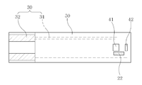
도 2는 도1 실시예에 따른 바이오센서의 부분 평면도,2 is a partial plan view of the biosensor according to the embodiment of FIG. 1;
도 3은 본 발명의 일 실시예에 따른 하부 기판의 평면도,3 is a plan view of a lower substrate according to an embodiment of the present invention;
도 4는 본 발명의 다른 실시예에 따른 하부 기판의 평면도,4 is a plan view of a lower substrate according to another embodiment of the present invention;
도 5는 본 발명의 다른 실시예에 따른 바이오센서의 분해사시도,5 is an exploded perspective view of a biosensor according to another embodiment of the present invention;
도 6은 도1 실시예에 따른 바이오센서의 단면도,6 is a cross-sectional view of the biosensor according to the embodiment of FIG. 1;
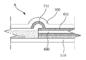
도 7 및 도 8은 도 6에 도시된 바이오센서의 일부를 확대한 도면,7 and 8 are enlarged views of a part of the biosensor shown in FIG. 6;
도 9는 본 발명의 일 실시예에 따른 바이오센서의 효과를 도시한 참고도이다.9 is a reference diagram showing the effect of the biosensor according to an embodiment of the present invention.
<도면부호의 간단한 설명><Brief Description of Drawings>
20,21,22 : 더미 전극20,21,22: dummy electrode
30 : 리드부30: lead part
31 : 리드선 32 : 리드 단자31: lead wire 32: lead terminal
41 : 기준 전극 42 : 작동 전극41: reference electrode 42: working electrode
50 : 절연막 70, 120 : 효소반응층50:
100 : 바이오센서100: biosensor
110 : 하부 기판110: lower substrate
130, 600 : 스페이서130, 600: spacer
131, 610 : 시료도입공간131, 610: sample introduction space
150, 700 : 상부 기판150, 700: upper substrate
151 : 만곡홈 153, 710 : 공기 배출공간151:
본 발명은 바이오센서에 관한 것으로, 특히 생체시료 내에 존재하는 분석물질을 전기화학적으로 측정하는 바이오센서에 관련된다. The present invention relates to a biosensor, and more particularly to a biosensor for electrochemically measuring analyte present in a biological sample.
바이오센서는 전기절연성의 기판상에 스크린 인쇄 등의 방법으로 복수의 전극을 포함하는 전극계를 형성하고, 형성된 전극계상에 친수성 고분자와 산화환원효소 및 전자수용체로 이루어지는 효소반응층을 형성한 것이다. 이러한 바이오센서는 전기화학적으로 시료 내의 분석물질을 측정하는 것으로 미국특허등록공보 제5,171,689호와 제5,387,328호에 기재되어 있다. The biosensor forms an electrode system including a plurality of electrodes on the electrically insulating substrate by screen printing or the like, and forms an enzyme reaction layer including a hydrophilic polymer, a redox enzyme, and an electron acceptor on the formed electrode system. Such biosensors are described in US Pat. Nos. 5,171,689 and 5,387,328 as electrochemically measuring analytes in a sample.
일반적으로, 전기화학적으로 시료 내의 분석물질을 측정하는 바이오센서는 작동 전극(Working electrode) 및 기준 전극(Reference electrode)을 구비한다. 일예로 산화환원효소(Oxidoreductase)와 전자전달매개물질을 이용한 전기화학적 센서의 측정 원리를 보면 아래의 반응식과 같다.In general, a biosensor for measuring analytes in a sample electrochemically includes a working electrode and a reference electrode. For example, the measuring principle of the electrochemical sensor using Oxidoreductase and an electron transfer mediator is shown below.
[반응식][Scheme]
분석물질 + 효소(환원상태) + 전자전달매개물질(산화상태) ===> 반응결과물질 + 효소(산화상태) + 전자전달매개물질(환원상태)Analyte + Enzyme (Reduced State) + Electron Transfer Mediator (oxidized state) ===> Reaction Result + Enzyme (oxidized State) + Electron Transfer Mediator (reduced state)
이 반응식에서 시료 내의 분석물질과 반응하여 생성된 환원상태의 전자전달매개물질은 시료 내에 존재하는 분석물질의 농도에 비례한다. 이를 이용하여 기준 전극(Reference electrode)을 기준으로 작동 전극(Working electrode)에 일정한 전압을 인가하여 환원상태의 전자전달매개물질을 산화시키며 이때 발생하는 산화 전류의 양을 측정하여 시료 내의 분석물질을 정량할 수 있다.In this scheme, the reduced electron transfer mediator produced by reacting with the analyte in the sample is proportional to the concentration of the analyte present in the sample. By using this, a certain voltage is applied to the working electrode based on the reference electrode to oxidize the electron transfer mediator in a reduced state, and the analyte in the sample is quantified by measuring the amount of oxidation current generated at this time. can do.
작동 전극(Working electrode) 및 기준 전극(Reference electrode)이 카본과 같은 물질로 이루어질 경우, 작동 전극(Working electrode)에서 전자전달 매개물질의 산화반응이 일어나면, 기준 전극(Reference electrode)에서는 환원 반응이 일어나게 되어 산화환원의 전자수를 맞추게 된다. 그런데 작동 전극(Working electrode) 및 기준 전극(Reference electrode)의 거리가 너무 가깝게 되면, 생체 시료가 효소 반응층에 주입되는 경우 기준 전극(Reference electrode)에서의 전자전달 매개물질(환원상태)이 작동 전극(Working electrode) 쪽으로 확산(diffusion)될 수 있다. 즉, 전극간 거리가 너무 가깝게 되면 작동 전극(Working electrode) 위에서 산화전류가 더 많이 발생이 되어, 전극 측정오차가 발생하게 된다. 이에 작동 전극(Working electrode) 및 기준 전극(Reference electrode) 간의 거리가 어느 정도 떨어져 있어야 한다. When the working electrode and the reference electrode are made of a material such as carbon, the oxidation reaction of the electron transfer mediator at the working electrode causes a reduction reaction at the reference electrode. The number of electrons of the redox is adjusted. However, when the distance between the working electrode and the reference electrode is too close, when the biological sample is injected into the enzyme reaction layer, the electron transfer mediator (reduced state) at the reference electrode becomes the working electrode. It may be diffused toward the working electrode. In other words, if the distance between the electrodes is too close, more oxidation current is generated on the working electrode, the electrode measurement error occurs. Thus, the distance between the working electrode and the reference electrode should be somewhat separated.
그러나, 작동 전극(Working electrode) 및 기준 전극(Reference electrode)의 거리가 너무 멀게 되면, 작동 전극(Working electrode) 및 기준 전극(Reference electrode) 사이에 노출되는 기판의 면적이 증가하게 된다. 그런데, 통상적으로 효소 수용액은 카본으로 형성된 전극 위에 잘 도포되지만 절연성 기판 위에는 잘 도포되지 않는다. 이는 전기절연성 기판은 카본보다 물에 대한 표면장력이 크기 때문이다. 또한, 절연성 기판은 카본으로 형성된 전극보다도 건조된 효소 반응층에 대한 흡착력이 좋지 못해서 건조된 효소반응층이 전극보다 기판에서 더 많이 들뜬다. 이에 두 전극 위에 놓여져 있는 효소반응층이 예컨대 생체 시료액 주입 시에 씻겨져 나가 정확한 측정이 이루어지지 않는 문제점이 있다. However, if the distance between the working electrode and the reference electrode is too far, the area of the substrate exposed between the working electrode and the reference electrode increases. By the way, the aqueous solution of enzyme is usually applied well on the electrode formed of carbon, but not well on the insulating substrate. This is because the electrically insulating substrate has a larger surface tension against water than carbon. In addition, the insulating substrate has a poor adsorption force on the dried enzyme reaction layer than the electrode formed of carbon, so that the dried enzyme reaction layer is more excited on the substrate than the electrode. Thus, there is a problem in that the enzyme reaction layer placed on the two electrodes is washed away, for example, when the biological sample solution is injected, so that accurate measurement is not performed.
본 발명은 상기와 같은 배경에서 제안된 것으로, 본 발명의 목적은 생체 시료액의 신속한 흡입을 유도하며 나아가 효소반응층에 생체 시료액 주입 시 용해된 효소가 작동 전극 또는 기준 전극에서 완전히 씻겨지는 것을 방지하여 측정오차를 최소화하는 바이오센서를 제공하는 것이다.The present invention has been proposed in the background as described above, and an object of the present invention is to induce rapid inhalation of a biological sample solution and furthermore, that the dissolved enzyme is completely washed off from the working electrode or the reference electrode when the biological sample solution is injected into the enzyme reaction layer. It is to provide a biosensor that prevents and minimizes measurement errors.
본 발명의 다른 목적은 바이오센서 제조 시, 효소 반응층이 하부 기판이나 절연막에서 들뜨는 것을 방지하는 바이오센서를 제공하는 것이다. Another object of the present invention is to provide a biosensor that prevents the enzyme reaction layer from being lifted up from the lower substrate or the insulating layer when the biosensor is manufactured.
상기 목적을 달성하기 위한 본 발명의 일 양상에 따른 바이오센서는, 전극 리드선을 통해 리드 단자와 연결되는 작동 전극과 기준 전극과, 시료 내에 존재하는 분석물질과 반응하는 효소반응층이 상기 전극들 위에 형성되는 절연성 하부기판, 하부기판과 소정의 상부기판을 접착하며 시료가 효소반응층을 따라 전극들의 위치까지 흡입되도록 유도하는 시료도입공간이 형성되는 스페이서 및 스페이서를 통해 하부기판과 마주보게 접착되는 절연성 상부기판을 포함하며, 하부기판에는 작동 전극 및 기준 전극과 이격되게 설치되어 효소 반응층을 고정하며 전극 리드선과 연결되지 않는 더미(dummy) 전극이 형성된 것을 특징으로 한다.In accordance with an aspect of the present invention, a biosensor includes a working electrode and a reference electrode connected to a lead terminal through an electrode lead wire, and an enzyme reaction layer reacting with an analyte present in a sample on the electrodes. The insulating lower substrate, the lower substrate and the predetermined upper substrate is bonded to each other and the insulating substrate is bonded to face the lower substrate through the spacer and the spacer is formed a sample introduction space for inducing the sample to be sucked to the position of the electrode along the enzyme reaction layer It includes an upper substrate, the lower substrate is spaced apart from the working electrode and the reference electrode is fixed to the enzyme reaction layer, characterized in that a dummy electrode is formed that is not connected to the electrode lead wire.
이 같은 양상에 따라 본 발명의 바이오센서는 하부 기판에 작동 전극 및 기준 전극외에 효소반응층을 고정하는 더미(dummy) 전극이 형성됨으로써, 효소 반응층에 생체 시료액이 주입되는 경우 용해된 효소가 작동 전극 또는 기준 전극에서 완전히 씻겨지는 것을 방지할 수 있다. 더 나아가 본 발명의 바이오센서 제조 시, 효소반응층이 기판이나 절연막에서 들뜨는 것을 방지할 수 있다.According to this aspect, the biosensor of the present invention has a dummy electrode for fixing the enzyme reaction layer in addition to the working electrode and the reference electrode on the lower substrate, so that the dissolved enzyme is injected when the biological sample solution is injected into the enzyme reaction layer. It can be prevented from being completely washed in the working electrode or the reference electrode. Furthermore, when manufacturing the biosensor of the present invention, it is possible to prevent the enzyme reaction layer from being lifted off the substrate or the insulating film.
바람직하게는, 하부기판에 형성되는 더미(dummy) 전극은 작동 전극 및 기준 전극과 동일한 재질, 예컨대 탄소, 흑연, 백금-탄소, 은, 금, 팔라듐, 또는 백금 중 하나로 구현된다. 이에 따라 본 발명의 바이오센서 제조공정은 하부 기판에 더미(dummy) 전극을 형성하기 위한 별도의 추가 공정이 필요치 않아 기존의 제조 공정을 그대로 유지할 수 있다. Preferably, the dummy electrode formed on the lower substrate is made of one of the same materials as the working electrode and the reference electrode, such as carbon, graphite, platinum-carbon, silver, gold, palladium, or platinum. Accordingly, the biosensor manufacturing process of the present invention does not need a separate additional process for forming a dummy electrode on the lower substrate can maintain the existing manufacturing process as it is.
전술한, 그리고 추가적인 본 발명의 양상들은 후술하는 실시예를 통해 더욱 명확해질 것이다. 이하에서는 첨부된 도면을 참조하여 기술되는 바람직한 실시예를 통하여 본 발명을 당업자가 용이하게 이해하고 재현할 수 있도록 상세히 설명하기로 한다. The foregoing and further aspects of the present invention will become apparent from the following examples. Hereinafter, the present invention will be described in detail with reference to the accompanying drawings so that those skilled in the art can easily understand and reproduce the present invention.
도 1은 본 발명의 다른 실시예에 따른 바이오센서의 분해사시도이고, 도 2는 바이오센서의 부분 평면도이다. 도 1및 도 2를 참조하면, 본 실시예에 따른 바이오센서는 크게 절연성 하부기판(110), 스페이서(600) 및 상부기판(700)을 포함한다. 1 is an exploded perspective view of a biosensor according to another embodiment of the present invention, and FIG. 2 is a partial plan view of the biosensor. 1 and 2, the biosensor according to the present exemplary embodiment includes an insulating
본 발명에 따라 시료 내에 존재하는 분석물질을 측정하는 바이오센서는, 적어도 하나 이상의 전극을 구비하고 시료 내에 존재하는 분석물질과 반응하는 효소반응층을 전극위에 형성하는 절연성 하부기판(110)과, 하부기판(600)과 상부기판(700)을 접착하며 시료가 효소반응층(120)을 따라 전극들(21,41,42)의 위치까지 흡입되도록 유도하는 시료도입공간(610)을 형성하는 스페이서(600) 및 하부기판과 마주보며 시료도입공간을 통해 시료와 함께 흡입된 공기가 배출되는 공기배출공간(710)을 구비한 절연성 상부기판(700)을 포함하며, 공기배출공간(710)은 시료도입공간(610)과 별개의 다른 층(layer)에 형성되는 입체모양인 것을 특징으로 한다.According to the present invention, a biosensor for measuring an analyte present in a sample includes an insulating
이 때, 공기배출공간은 시료의 흡입속도를 높이기 위하여 시료도입공간(610)과 별개의 다른 층에 터널 형태로 형성되는 것이 바람직하며, 특히 공기배출공간(710)은 시료의 흡입방향과 수직한 방향으로 형성된 반원통형의 형상인 것이 바람직하다.At this time, the air discharge space is preferably formed in a tunnel form in a different layer separate from the
하부기판(110)은 50~400um의 두께를 가지는 절연성 물질이 사용될 수 있다. 하부기판(110)은 일측 끝단에 리드 단자(32)와 각각의 리드 단자(32)로부터 뻗어 있는 리드선(31)을 포함하는 리드부(30)가 형성된다. 또한, 하부기판(110)은 리드선(31)과 연결되는 전극들(21,41,42)이 스크린 프린팅 기법으로 형성된다. 전극들(21,41,42)은 탄소, 흑연, 백금 처리된 탄소, 은, 금, 팔라듐 또는 백금 성분 등을 이용하여 제작된다. 예를 들면, 탄소나 백금 처리된 탄소로 구성된 잉크, 또는 팔라듐을 포함하는 잉크를 사용하여 하부 기판(110)에 전극을 인쇄할 수 있다. The
이러한 전극들(21,41,42)에서 참조부호 21은 더미(dummy) 전극이며, 41은 기 준 전극이며, 42는 작동 전극이다. 여기서 기준 전극(41)과 작동 전극(42)은 후술할 효소반응층(70)에서 전자수용체 산화 혹은 환원시 발생하는 전류량을 검출하는 역할을 수행한다. 더미(dummy) 전극(21)은 작동 전극(42) 및 기준 전극(41)과 이격되어 효소반응층(70)을 고정하며 전극 리드선과 연결되지 않는다. 이러한 더미(dummy) 전극(21)은 효소 반응층(70)에 생체 시료액이 주입되는 경우 용해된 효소가 작동 전극(42) 또는 기준 전극(41)에서 완전히 씻겨지는 것을 방지하고, 나아가 본 발명의 바이오센서 제조 시, 효소반응층(70)이 하부기판(110)이나 절연막(50)에 완전히 고정되지 않고 들뜨는 것을 방지하는 역활을 한다. 도1에 도시한 바와 같이, 더미(dummy) 전극(21)은 작동 전극(42)과 기준 전극(41) 사이에 형성될 수 있다. In these
효소반응층(120)은 시료가 흡입되어 반응을 일으키기 위한 층으로, 시료 내의 분석물질과 반응하는 효소와, 효소와 반응하는 전자전달매개물질, 그리고 완충용액 물질, 효소 안정제, 기타 이러한 구성 물질들을 전극 위에 고정하는 고분자 지지체로 구성된다. 효소반응층(120)은 전극들(21,41,42) 위에 도포되어 고정된다. The
여기서, 효소로는 글루코스 산화효소, 락테이트 산화효소, 콜레스테롤 산화효소, 알코올 산화효소 등 여러 종류의 산화환원효소와, 글루코스 탈수소효소, GOT(glutamate oxaloacPETate trnasmianse), GPT(glutamate pyruvate trnasmianse)등 여러 종류의 전이효소와 가수분해효소가 사용될 수 있다. 또한, 전자전달매개물질로는 포타슘페리시안나이드(potassium ferricyanide), 포타슘페로시안나이 드(potassium ferrocyanide), 헥사아민루세늄클로라이드(hexaamineruthenium chloride), 페로센(ferrocene) 및 그 유도체, 퀴논(quinine) 및 그 유도체 등 효소와 반응하여 산화 또는 환원 할 수 있는 물질들이 사용될 수 있다.Here, enzymes include various kinds of oxidoreductases such as glucose oxidase, lactate oxidase, cholesterol oxidase, alcohol oxidase, glucose dehydrogenase, GOT (glutamate oxaloac PET trnasmianse) and GPT (glutamate pyruvate trnasmianse). Transferase and hydrolase may be used. In addition, as the electron transfer mediators, potassium ferricyanide, potassium ferrocyanide, hexaamineruthenium chloride, ferrocene and its derivatives, quinine and quinine Substances that can be oxidized or reduced by reacting with enzymes such as derivatives thereof can be used.
효소 반응층(120)에 분석물질을 포함한 시료를 떨어뜨리면, 시료에 의해 효소반응층(120)이 용해되며 시료 내에 포함된 분석물질과 효소(Enzyme)가 반응하여 분석물질이 산화되고, 이에 따라 전자수용체가 환원된다. 효소반응 종료 후 이 환원된 전자수용체를 전기화학적으로 산화하여 얻어지는 산화 전류치를 전극(41 ,42)과 연결된 리드선(32)에 접촉되는 측정 장치(도면 도시 생략)를 통해 측정함으로써 시료 중에 포함된 분석물질의 농도를 구할 수 있다.When the sample containing the analyte is dropped in the
스페이서(600)는 상부기판(700)과 하부기판(110)을 접착하여 형성되는 시료도입공간(610)를 통해 모세관을 형성한다. 스페이서(600)의 두께는 효소반응층(120)의 두께보다 적어도 같거나 두꺼워야 한다. 그 이유는 시료가 효소반응층(120)에 흡입 시 시료 주입을 보다 용이하도록 하기 위함이다. 즉, 스페이서(600)의 두께가 효소반응층(120)의 두께보다 클 경우 그 여유 공간으로 시료 주입이 용이해진다. 스페이서(600)는 양면테이프로 구성되며 10~300um의 두께를 가지는 양면테이프를 사용할 수 있다. 특히, 주입되는 시료의 양을 최소로 하기 위하여 양면테이프의 두께를 10~150um로 하는 것이 바람직하다. 시료도입공간(610)을 통해 측정하고자 하는 시료가 모세관 현상으로 자동 주입되며, 시료도입공간(610)에 존재하던 공기는 시료의 유입으로 인해 상부기판(700)에 형성된 공기배출공간(710)을 통해 외부로 배출된다.The
이 때, 공기배출공간(710)은 시료의 흡입속도를 높이기 위하여 시료도입공간과 별개의 다른 층(layer)에 형성되는 입체모양인 것이 바람직하며, 특히 시료도입공간(610)과 별개의 다른 층에 터널 형태로 형성되는 것이 바람직하다. 즉, 공기배출공간(710)은 시료와 효소반응층(120)이 존재할 수 없는 층(layer)에 형성되는 것으로 이를 통해서 공기만 빠져나가게 된다. 특히 공기배출공간(710)은 시료의 흡입방향과 수직한 방향으로 형성된 반원통형의 형상인 것이 바람직하며, 그 이외에도 다양한 입체형상으로 구현될 수 있다.In this case, the
이에 따라, 효소반응층(120)에 시료가 흡입되기 시작하면, 효소반응층 주변에 존재하던 공기는 점점 시료도입공간(610) 안쪽으로 밀리게 되고, 압력에 의해 상부기판(700)에 시료주입방향과 수직한 방향으로 형성된 공기배출공간(710)을 통해 공기가 외부로 배출되게 된다. 시료도입공간(610)과 별개의 다른 층에 터널 형태로 형성되는 공기배출공간(710)을 통해 공기만 외부로 배출됨에 따라 시료흡입 속도가 향상되게 된다.Accordingly, when the sample is sucked into the
즉, 본원 발명은 종래의 기술들과는 달리 산화 반응이 일어나는 효소반응층(120)과 공기가 배출되는 공기배출공간(710)이 별도의 다른 층(Layer)에 형성되므로, 측정에 필요한 시료의 양이 공기배출공간(710)의 크기에 무관하여 시료 양을 효소반응층(120) 크기만큼으로 줄일 수 있다. 또한, 공기배출공간(710)을 효소반응층(120)의 크기에 상관없이 늘릴 수 있어 효율적인 공기배출이 가능하며, 공기배출이 효소반응층(120)을 거치지 않고 일어나게 되어 공기 배출 속도와 시료 주입속도가 무관하고, 이에 따라 기체인 공기의 움직임이 액체인 시료의 움직임 보다 윌 등히 빠르므로 공기배출 속도가 향상되어 결과적으로 시료흡입속도를 높일 수 있다. 나아가, 측정 후 바이오센서(스트립)를 측정장치에서 제거할 때 시료가 손에 묻을 염려가 적다.That is, in the present invention, unlike the conventional techniques, since the
이하, 도 3 내지 도 4는 더미(dummy) 전극이 하부 기판 상에 배치되는 실시예를 도시한다. 본 실시예에서는 더미(dummy) 전극이 1개인 것을 예시하지만, 본 발명은 이에 한정되지 않고 2개이상 사용될 수 있다. 또한, 작동 전극과 기준 전극이 각각 1개인 것을 예시하였지만, 본 발명은 이에 한정되지 않고, 작동 전극이 2개인 바이오센서에도 하부 기판 상에 더미(dummy) 전극이 형성될 수 있다. 3 to 4 illustrate embodiments in which a dummy electrode is disposed on a lower substrate. In the present exemplary embodiment, one dummy electrode is illustrated, but the present invention is not limited thereto, and two or more dummy electrodes may be used. In addition, although one working electrode and one reference electrode have been exemplified, the present invention is not limited thereto, and a dummy electrode may be formed on a lower substrate even in a biosensor having two working electrodes.
도 3 에 도시한 바와 같이, 더미(dummy) 전극(22)은 작동 전극(42) 및 기준 전극(41)과 이웃하는 위치에 형성될 수 있으며, 도 4 에 도시한 바와 같이, 더미(dummy) 전극(23)은 효소반응층(70)이 형성되는 하부기판의 끝단에서 기판의 중심 방향으로 형성될 수 있다. 바이오센서 절단면에 효소반응층(70)과 흡착력이 좋은 더미(dummy) 전극(22)이 형성됨으로써, 바이오센서를 절단하는 공정에서 효소 반응층이 깨지는 위험성을 줄일 수 있다. As shown in FIG. 3, the
도 5는 본 발명에 따른 바이오센서의 분해사시도이다. 도시한 바와 같이, 본 발명에 따른 바이오센서(100)는 크게 하부 기판(110)과 스페이서(130)와 상부 기판(150)을 포함한다. 5 is an exploded perspective view of the biosensor according to the present invention. As shown, the
하부기판(110)은 50~400um의 두께를 가지는 절연성 물질이 사용될 수 있다. 하부기판(110)은 일측 끝단에 리드 단자(32)와 각각의 리드 단자(32)로부터 뻗어 있는 리드선(31)을 포함하는 리드부(30)가 형성된다. 또한, 하부기판(110)은 리드 선(31)과 연결되는 전극들(21,41,42)이 스크린 프린팅 기법으로 형성된다. 전극들(21,41,42)은 탄소, 흑연, 백금 처리된 탄소, 은, 금, 팔라듐 또는 백금 성분 등을 이용하여 제작된다. 예를 들면, 탄소나 백금 처리된 탄소로 구성된 잉크, 또는 팔라듐을 포함하는 잉크를 사용하여 하부 기판(110)에 전극을 인쇄할 수 있다. The
이러한 전극들(21,41,42)에서 참조부호 21은 더미(dummy) 전극이며, 41은 기준 전극이며, 42는 작동 전극이다. 여기서 기준 전극(41)과 작동 전극(42)은 후술할 효소반응층(70)에서 전자수용체 산화 혹은 환원시 발생하는 전류량을 검출하는 역할을 수행한다. 더미(dummy) 전극(21)은 작동 전극(42) 및 기준 전극(41)과 이격되어 효소반응층(70)을 고정하며 전극 리드선과 연결되지 않는다. 이러한 더미(dummy) 전극(21)은 효소 반응층(70)에 생체 시료액이 주입되는 경우 용해된 효소가 작동 전극(42) 또는 기준 전극(41)에서 완전히 씻겨지는 것을 방지하고, 나아가 본 발명의 바이오센서 제조 시, 효소반응층(70)이 하부기판(110)이나 절연막(50)에 완전히 고정되지 않고 들뜨는 것을 방지하는 역활을 한다. 도1에 도시한 바와 같이, 더미(dummy) 전극(21)은 작동 전극(42)과 기준 전극(41) 사이에 형성될 수 있다. In these
또한, 하부기판(110)은 전극들(21,41,42) 위에 효소반응층(70)이 도포되어 고정된다. 효소반응층(70)은 시료 내의 분석물질과 반응하는 효소와, 효소와 반응하는 전자전달매개물질, 그리고 완충용액 물질, 효소 안정제, 기타 이러한 구성 물질들을 전극들(21,41,42)에 고정하는 고분자 지지체로 구성된다. In addition, the
스페이서(130)는 하부기판(110)과 상부기판(150)을 접착하며 시료가 효소반 응층(70)을 따라 전극들(21,41,42)의 위치까지 흡입되도록 유도하는 시료도입공간(131)이 형성된다.The
상부기판(150)은 PET, PVC 또는 폴리카본에이트로 구성된 얇은 판이 사용될 수 있다. 상부기판(150)은 모세관 현상에 의해 시료(예 :혈액)가 효소반응층(70)에 주입되도록 스페이서(130)에 의해 형성되는 시료도입공간(131) 내의 공기를 배출시키는 공기배출구(153)가 형성된다. 이러한 공기배출구(153)는 상부기판(150)의 일 끝단에서 전극들(21,41,42)이 형성되어 있는 방향으로 만곡되어 있는 만곡홈(151)으로부터 형성되기 시작하여 적어도 전극들(21,41,42) 위까지 연장된다. The
도 6은 도1 실시예에 따른 바이오센서의 단면도이다. 도 6을 참조하면, 절연성 하부기판(110) 위에 전극들(21,41,42)이 형성되며, 전극들(21,41,42) 위에는 효소반응층(120)이 고정된다. 이러한 하부기판(110)은 시료도입공간(610)을 가지는 스페이서(600)에 의해 상부기판(700)과 결합된다. 상부 기판(700)에는 시료도입공간(610)를 통해 시료가 주입됨에 따라 공기가 배출되는 공기배출공간(710)이 시료주입방향과 수직한 방향의 터널 형태로 형성되어 있다. 6 is a cross-sectional view of the biosensor according to the embodiment of FIG. 1. Referring to FIG. 6,
본 발명의 바이오센서는 공기배출공간(710)을 통해 공기만 빠른 속도로 배출되고 시료는 외부로 유출되지 않는 피 퍼짐 현상을 방지하고자 다양한 해결책을 구비하고 있다. 도 7 및 도 8은 도 6에 도시된 바이오센서의 일부를 확대한 도면이다.Biosensor of the present invention has a variety of solutions in order to prevent the spreading phenomenon that only the air is discharged at a high speed through the
피 퍼짐 현상을 방지하기 위한 첫 번째 해결책은 공기배출공간(710)의 폭(Width)과 높이(Height)를 제한하는 것이다. 공기배출공간의 단면이 너무 작을 경우 모세관 현상(capillary action)에 의해 피 퍼짐 현상이 발생할 수 있다. 따라서 공기배출공간(710)의 단면적을 크게 할수록 모세관 현상을 방지하고 공기의 배출속도를 높여 시료흡입속도를 향상시킬 수 있다. 그러나, 공기배출공간(710)을 무제한 크게 할 수는 없다. 공기배출공간의 모양이 터널 형태의 입체모양이므로 단면적이 너무 커지면 바이오센서 제작과정에서 공기배출공간의 모양(forming)을 제대로 형성하기 힘들며, 공기배출공간을 형성한 후에도 눌리거나 모양이 틀어질 염려가 있기 때문이다.The first solution to prevent the spreading phenomenon is to limit the width and height of the air discharge space (710). If the cross section of the air outlet space is too small, the phenomenon of blood flow may be caused by a capillary action. Therefore, as the cross-sectional area of the
따라서, 실험적으로 얻어진 결과에 따르면 본 발명에 따른 바이오센서에 있어서, 공기배출공간(710)의 단면은 약 0.3mm ~ 3mm 내외의 폭과, 약 0.1mm ~ 3mm 내외의 높이를 가지는 것이 바람직하다. 이때 시료도입공간을 통해 주입되는 시료는 약 1㎕이하인 것이 특히 바람직하다. Therefore, according to the experimentally obtained results, in the biosensor according to the present invention, it is preferable that the cross section of the
피 퍼짐 현상을 방지하기 위한 두 번째 해결책은 시료 및 시료에 용해된 효소반응층(120)이 친수성인 성질을 이용하여 소수성 재질로 공기배출공간(710)의 내부를 도포하는 것이다.The second solution to prevent the spreading phenomenon is to apply the inside of the
도 7 및 도 8에 도시된 바와 같이, 터널 형태의 공기배출공간의 내벽은 피 퍼짐 현상을 방지하기 위하여 소수성이 강한 물질로 도포하는 것이 바람직하다. 이에 따라 친수성이 강한 시료가 공기배출공간(710)으로 퍼져나가지 못하도록 피 퍼짐 현상을 방지할 수 있다. 또한, 스페이서는 피 퍼짐을 방지하기 위하여 소수성 재질을 사용하는 것이 바람직하다. 나아가 도 7 및 도 8에 도시된 바와 같이, 스페이서(600)의 상부기판이나 하부기판과 접촉하는 면에 소수성이 강한 재질의 접착 제를 도포하는 것이 바람직하다. As shown in Figures 7 and 8, it is preferable that the inner wall of the tunnel-type air discharge space is coated with a material having a high hydrophobicity in order to prevent the spreading phenomenon. Accordingly, the spreading phenomenon may be prevented so that the hydrophilic sample does not spread to the
즉, 시료가 효소반응층(120)에 흡입될 때 시료가 효소반응층(120) 외부로 스며들지 않도록 하기위해, 효소반응층(120)에 흡입되는 친수성(Hydrophilic) 있는 시료의 진로를 방해할 수 있는 소수성(Hydrophobic) 재질을 이용해 효소반응층(120)주변을 구현함으로써 센서 내/외부로 시료가 스며들지 않도록 할 수 있다. That is, in order to prevent the sample from penetrating outside the
피 퍼짐 현상을 방지하기 위한 세 번째 해결책은 스페이서(600)에 형성되는 시료도입공간(610)의 끝부분 모양을 점차 좁아지도록 형성하는 것이다. 도 9에 도시된 바와 같이 시료도입공간(610)은 공기배출공간(710)과 만나는 끝부분에서의 피 퍼짐을 방지하기 위하여 시료도입공간(610)의 끝부분을 점차 좁아지도록 형성하는 것이 바람직하다.A third solution to prevent the spreading phenomenon is to form the end shape of the
도 9는 본 발명의 일 실시예에 따른 바이오센서의 효과를 도시한 참고도이다. 도 9를 참조하면, 본 발명의 특징적인 양상에 따라 형성되는 바이오센서에 의해 주입되는 시료는 효소반응층(120)과 같은 모양의 시료도입공간(610) 내에만 머물고 주변으로 퍼지지 않아 피 퍼짐 현상을 방지할 수 있으며 측정에 필요한 시료의 양을 최소화할 수 있다. 동시에 시료도입공간(610)과 별도의 층에 형성된 입체 모양으로 형성되어 상대적으로 부피가 큰 공기배출공간(710)을 통해 공기만 원활하게 빠져 나갈 수 있다. 이에 따라 시료 흡입 속도는 향상되면서도 피 퍼짐 현상을 방지할 수 있는 효율적인 바이오센서가 제공된다.9 is a reference diagram showing the effect of the biosensor according to an embodiment of the present invention. Referring to FIG. 9, the sample injected by the biosensor formed according to the characteristic aspect of the present invention stays in the
상술한 바와 같이, 본 발명에 따른 바이오센서는 시료도입공간이 상부 기판 의 공기배출구에 의해 오픈되어 있기 때문에 모세관 효과가 극대화되어 생체 시료액의 유입이 신속하게 이루질 수 있는 유용한 효과가 있다. As described above, the biosensor according to the present invention has a useful effect that the capillary effect is maximized because the sample introduction space is opened by the air outlet of the upper substrate, so that the inflow of the biological sample liquid can be made quickly.
또한, 본 발명의 바이오센서는 하부 기판에 작동 전극 및 기준 전극외에 효소반응층을 고정하는 더미(dummy) 전극이 형성됨으로써, 효소 반응층에 생체 시료액이 주입되는 경우 용해된 효소가 작동 전극 또는 기준 전극에서 완전히 씻겨지는 것을 방지할 수 있는 유용한 효과가 있다. 또한 본 발명의 바이오센서 제조 시, 효소 반응층이 절연성 기판이나 절연막에 완전히 고정되지 않고 들뜨는 것을 방지할 수 있는 유용한 효과가 있다. 또한, 하부기판에 형성되는 더미(dummy) 전극이 작동 전극 및 기준 전극과 동일한 재질로 구현됨으로써, 본 발명의 바이오센서 제조공정은 하부 기판에 더미(dummy) 전극을 형성하기 위한 별도의 추가 공정이 필요치 않아 기존의 제조 공정을 그대로 유지할 수 있는 유용한 효과가 있다. In addition, the biosensor of the present invention is formed in the lower substrate by the dummy electrode for fixing the enzyme reaction layer in addition to the working electrode and the reference electrode, when the biological sample solution is injected into the enzyme reaction layer is dissolved enzyme working electrode or There is a useful effect that can be prevented from being completely washed at the reference electrode. In addition, when manufacturing the biosensor of the present invention, there is a useful effect that the enzyme reaction layer can be prevented from lifting without being completely fixed to the insulating substrate or the insulating film. In addition, the dummy electrode formed on the lower substrate is implemented by the same material as the working electrode and the reference electrode, the biosensor manufacturing process of the present invention is a separate additional process for forming a dummy electrode on the lower substrate Since it is not necessary, there is a useful effect of maintaining the existing manufacturing process as it is.
본 발명에 따른 시료 흡입속도를 향상한 바이오센서는 시료주입방향과 되도록이면 수직한 방향으로 시료주입공간과는 별개의 다른 층에 상부기판에 입체모양의 공기배출공간을 형성함으로써, 시료 흡입시 공기가 외부로 매우 효과적으로 배출됨으로써 시료흡입속도를 향상시킬 수 있다. 또한, 시료가 공기배출공간을 통해 주변으로 퍼져나가지 않도록 다양한 해결책을 제시하여 시료 누출의 염려가 없는 유용한 효과를 가진다.The biosensor with improved sample suction speed according to the present invention forms a three-dimensional air discharge space on the upper substrate on a different layer from the sample injection space in a direction perpendicular to the sample injection direction, preferably in a direction perpendicular to the sample injection direction. Can be effectively discharged to the outside to improve the sample suction rate. In addition, by presenting a variety of solutions so that the sample does not spread to the surroundings through the air discharge space has a useful effect without fear of sample leakage.
본 발명은 첨부된 도면을 참조하여 바람직한 실시예를 중심으로 기술되었지만 당업자라면 이러한 기재로부터 본 발명의 범주를 벗어남이 없이 많은 다양한 자명한 변형이 가능하다라는 것은 명백하다. 따라서, 이러한 많은 변형예들을 포함하 도록 기술된 특허청구범위에 의해서 해석되어져야 할 것이다.Although the present invention has been described with reference to the accompanying drawings, it will be apparent to those skilled in the art that many various obvious modifications are possible without departing from the scope of the invention from this description. Therefore, it should be interpreted by the claims described to include many such variations.
Claims (8)
Priority Applications (4)
| Application Number | Priority Date | Filing Date | Title |
|---|---|---|---|
| KR1020060120043A KR100829400B1 (en) | 2006-11-30 | 2006-11-30 | Biosensor |
| EP07003914A EP1927851A3 (en) | 2006-11-30 | 2007-02-26 | Biosensor |
| CN2007100056238A CN101191783B (en) | 2006-11-30 | 2007-03-06 | Biosensor and method for measuring the same |
| US11/682,910 US20080128278A1 (en) | 2006-11-30 | 2007-03-07 | Biosensor |
Applications Claiming Priority (1)
| Application Number | Priority Date | Filing Date | Title |
|---|---|---|---|
| KR1020060120043A KR100829400B1 (en) | 2006-11-30 | 2006-11-30 | Biosensor |
Publications (1)
| Publication Number | Publication Date |
|---|---|
| KR100829400B1 true KR100829400B1 (en) | 2008-05-15 |
Family
ID=39144575
Family Applications (1)
| Application Number | Title | Priority Date | Filing Date |
|---|---|---|---|
| KR1020060120043A Expired - Fee Related KR100829400B1 (en) | 2006-11-30 | 2006-11-30 | Biosensor |
Country Status (4)
| Country | Link |
|---|---|
| US (1) | US20080128278A1 (en) |
| EP (1) | EP1927851A3 (en) |
| KR (1) | KR100829400B1 (en) |
| CN (1) | CN101191783B (en) |
Cited By (2)
| Publication number | Priority date | Publication date | Assignee | Title |
|---|---|---|---|---|
| KR101507317B1 (en) | 2013-04-02 | 2015-03-31 | (주)에스팩솔루션 | A biomaterial sensing semiconductor chip |
| WO2019083206A1 (en) * | 2017-10-23 | 2019-05-02 | 주식회사 비바이오 | Biosensor robust against coffee ring effect |
Families Citing this family (10)
| Publication number | Priority date | Publication date | Assignee | Title |
|---|---|---|---|---|
| USD587142S1 (en) | 2006-12-22 | 2009-02-24 | Abbott Diabetes Care Inc. | Sensors |
| CN103454321B (en) * | 2013-03-28 | 2015-09-09 | 利多(香港)有限公司 | Biosensor and its manufacturing method |
| CN103412012B (en) * | 2013-03-28 | 2015-09-09 | 利多(香港)有限公司 | biological sensor |
| US9523653B2 (en) | 2013-05-09 | 2016-12-20 | Changsha Sinocare Inc. | Disposable test sensor with improved sampling entrance |
| US9518951B2 (en) | 2013-12-06 | 2016-12-13 | Changsha Sinocare Inc. | Disposable test sensor with improved sampling entrance |
| US9897566B2 (en) | 2014-01-13 | 2018-02-20 | Changsha Sinocare Inc. | Disposable test sensor |
| US9939401B2 (en) | 2014-02-20 | 2018-04-10 | Changsha Sinocare Inc. | Test sensor with multiple sampling routes |
| TWI551860B (en) * | 2015-07-17 | 2016-10-01 | 台欣生物科技研發股份有限公司 | Test strip |
| WO2019003328A1 (en) * | 2017-06-28 | 2019-01-03 | 佳則 山口 | Measuring pipette tip, and measurement device and measurement method using said measuring pipette tip |
| USD912843S1 (en) | 2018-11-06 | 2021-03-09 | Lumiradx Uk Ltd | Test strip |
Citations (3)
| Publication number | Priority date | Publication date | Assignee | Title |
|---|---|---|---|---|
| KR960024350A (en) * | 1994-12-08 | 1996-07-20 | 구자홍 | Multi-electrode Biosensor |
| WO2003098165A1 (en) * | 2002-05-14 | 2003-11-27 | Abbott Laboratories | Biosensor having electrode for determining the rate of flow of a liquid |
| US20040197935A1 (en) | 1997-10-16 | 2004-10-07 | Forrow Nigel J. | Biosensor electrode mediators for regeneration of cofactors |
Family Cites Families (9)
| Publication number | Priority date | Publication date | Assignee | Title |
|---|---|---|---|---|
| US5582697A (en) * | 1995-03-17 | 1996-12-10 | Matsushita Electric Industrial Co., Ltd. | Biosensor, and a method and a device for quantifying a substrate in a sample liquid using the same |
| US5628890A (en) * | 1995-09-27 | 1997-05-13 | Medisense, Inc. | Electrochemical sensor |
| US6340428B1 (en) * | 1998-04-02 | 2002-01-22 | Matsushita Electric Industrial Co., Inc. | Device and method for determining the concentration of a substrate |
| JP2000046782A (en) * | 1998-07-30 | 2000-02-18 | Matsushita Electric Ind Co Ltd | Biosensor |
| JP3267936B2 (en) * | 1998-08-26 | 2002-03-25 | 松下電器産業株式会社 | Biosensor |
| US20030175946A1 (en) * | 2001-04-16 | 2003-09-18 | Hiroyuki Tokunaga | Biosensor |
| KR100426638B1 (en) * | 2001-07-07 | 2004-04-08 | 주식회사 인포피아 | Glucose strip sensor and glucose measurement method by the strip sensor |
| US6942770B2 (en) * | 2002-04-19 | 2005-09-13 | Nova Biomedical Corporation | Disposable sub-microliter volume biosensor with enhanced sample inlet |
| US20060070878A1 (en) * | 2004-10-06 | 2006-04-06 | Shu-Mei Wu | Electrochemical biosensor strip |
-
2006
- 2006-11-30 KR KR1020060120043A patent/KR100829400B1/en not_active Expired - Fee Related
-
2007
- 2007-02-26 EP EP07003914A patent/EP1927851A3/en not_active Withdrawn
- 2007-03-06 CN CN2007100056238A patent/CN101191783B/en not_active Expired - Fee Related
- 2007-03-07 US US11/682,910 patent/US20080128278A1/en not_active Abandoned
Patent Citations (3)
| Publication number | Priority date | Publication date | Assignee | Title |
|---|---|---|---|---|
| KR960024350A (en) * | 1994-12-08 | 1996-07-20 | 구자홍 | Multi-electrode Biosensor |
| US20040197935A1 (en) | 1997-10-16 | 2004-10-07 | Forrow Nigel J. | Biosensor electrode mediators for regeneration of cofactors |
| WO2003098165A1 (en) * | 2002-05-14 | 2003-11-27 | Abbott Laboratories | Biosensor having electrode for determining the rate of flow of a liquid |
Cited By (2)
| Publication number | Priority date | Publication date | Assignee | Title |
|---|---|---|---|---|
| KR101507317B1 (en) | 2013-04-02 | 2015-03-31 | (주)에스팩솔루션 | A biomaterial sensing semiconductor chip |
| WO2019083206A1 (en) * | 2017-10-23 | 2019-05-02 | 주식회사 비바이오 | Biosensor robust against coffee ring effect |
Also Published As
| Publication number | Publication date |
|---|---|
| CN101191783B (en) | 2011-12-21 |
| EP1927851A2 (en) | 2008-06-04 |
| US20080128278A1 (en) | 2008-06-05 |
| CN101191783A (en) | 2008-06-04 |
| EP1927851A3 (en) | 2009-01-21 |
Similar Documents
| Publication | Publication Date | Title |
|---|---|---|
| CN101178373B (en) | biological sensor | |
| CN101191783B (en) | Biosensor and method for measuring the same | |
| US7138041B2 (en) | Electrochemical biosensor by screen printing and method of fabricating same | |
| JP4879459B2 (en) | Electrochemical biosensor strip for analysis of liquid samples | |
| CN1205474C (en) | biological sensor | |
| CN100339701C (en) | Biosensor | |
| CN1207563C (en) | Biosensor | |
| US8357276B2 (en) | Small volume test strips with large sample fill ports, supported test strips, and methods of making and using same | |
| CN1514937A (en) | Electrochemical Biosensor | |
| KR20060089464A (en) | Electrochemical Biosensor | |
| CN104280431A (en) | Reagent composition for biosensor and biosensor comprising same | |
| JP2018036091A (en) | Biosensor and method of manufacturing the same | |
| TW201506396A (en) | Electrochemical-based analytical test strip with a soluble electrochemically-active coating opposite a bare electrode | |
| US20040251132A1 (en) | Reduced volume strip | |
| KR100903946B1 (en) | Biosensor | |
| CN219245429U (en) | Biological sensor | |
| US7655120B2 (en) | Biosensor | |
| KR100739865B1 (en) | Biosensor | |
| KR100879797B1 (en) | Bio sensor | |
| EP1909096A1 (en) | Biosensor | |
| CN101162213A (en) | Biosensor and method for measuring the same |
Legal Events
| Date | Code | Title | Description |
|---|---|---|---|
| A201 | Request for examination | ||
| PA0109 | Patent application |
St.27 status event code: A-0-1-A10-A12-nap-PA0109 |
|
| PA0201 | Request for examination |
St.27 status event code: A-1-2-D10-D11-exm-PA0201 |
|
| P11-X000 | Amendment of application requested |
St.27 status event code: A-2-2-P10-P11-nap-X000 |
|
| P13-X000 | Application amended |
St.27 status event code: A-2-2-P10-P13-nap-X000 |
|
| D13-X000 | Search requested |
St.27 status event code: A-1-2-D10-D13-srh-X000 |
|
| D14-X000 | Search report completed |
St.27 status event code: A-1-2-D10-D14-srh-X000 |
|
| E902 | Notification of reason for refusal | ||
| PE0902 | Notice of grounds for rejection |
St.27 status event code: A-1-2-D10-D21-exm-PE0902 |
|
| P11-X000 | Amendment of application requested |
St.27 status event code: A-2-2-P10-P11-nap-X000 |
|
| P13-X000 | Application amended |
St.27 status event code: A-2-2-P10-P13-nap-X000 |
|
| PN2301 | Change of applicant |
St.27 status event code: A-3-3-R10-R13-asn-PN2301 St.27 status event code: A-3-3-R10-R11-asn-PN2301 |
|
| E701 | Decision to grant or registration of patent right | ||
| PE0701 | Decision of registration |
St.27 status event code: A-1-2-D10-D22-exm-PE0701 |
|
| GRNT | Written decision to grant | ||
| PR0701 | Registration of establishment |
St.27 status event code: A-2-4-F10-F11-exm-PR0701 |
|
| PR1002 | Payment of registration fee |
St.27 status event code: A-2-2-U10-U11-oth-PR1002 Fee payment year number: 1 |
|
| PG1601 | Publication of registration |
St.27 status event code: A-4-4-Q10-Q13-nap-PG1601 |
|
| R18-X000 | Changes to party contact information recorded |
St.27 status event code: A-5-5-R10-R18-oth-X000 |
|
| R18-X000 | Changes to party contact information recorded |
St.27 status event code: A-5-5-R10-R18-oth-X000 |
|
| PR1001 | Payment of annual fee |
St.27 status event code: A-4-4-U10-U11-oth-PR1001 Fee payment year number: 4 |
|
| PR1001 | Payment of annual fee |
St.27 status event code: A-4-4-U10-U11-oth-PR1001 Fee payment year number: 5 |
|
| FPAY | Annual fee payment |
Payment date: 20130507 Year of fee payment: 6 |
|
| PR1001 | Payment of annual fee |
St.27 status event code: A-4-4-U10-U11-oth-PR1001 Fee payment year number: 6 |
|
| R18-X000 | Changes to party contact information recorded |
St.27 status event code: A-5-5-R10-R18-oth-X000 |
|
| FPAY | Annual fee payment |
Payment date: 20140605 Year of fee payment: 7 |
|
| PR1001 | Payment of annual fee |
St.27 status event code: A-4-4-U10-U11-oth-PR1001 Fee payment year number: 7 |
|
| FPAY | Annual fee payment |
Payment date: 20150430 Year of fee payment: 8 |
|
| PR1001 | Payment of annual fee |
St.27 status event code: A-4-4-U10-U11-oth-PR1001 Fee payment year number: 8 |
|
| R18-X000 | Changes to party contact information recorded |
St.27 status event code: A-5-5-R10-R18-oth-X000 |
|
| FPAY | Annual fee payment |
Payment date: 20160426 Year of fee payment: 9 |
|
| PR1001 | Payment of annual fee |
St.27 status event code: A-4-4-U10-U11-oth-PR1001 Fee payment year number: 9 |
|
| R18-X000 | Changes to party contact information recorded |
St.27 status event code: A-5-5-R10-R18-oth-X000 |
|
| PN2301 | Change of applicant |
St.27 status event code: A-5-5-R10-R13-asn-PN2301 St.27 status event code: A-5-5-R10-R11-asn-PN2301 |
|
| LAPS | Lapse due to unpaid annual fee | ||
| PC1903 | Unpaid annual fee |
St.27 status event code: A-4-4-U10-U13-oth-PC1903 Not in force date: 20170508 Payment event data comment text: Termination Category : DEFAULT_OF_REGISTRATION_FEE |
|
| PC1903 | Unpaid annual fee |
St.27 status event code: N-4-6-H10-H13-oth-PC1903 Ip right cessation event data comment text: Termination Category : DEFAULT_OF_REGISTRATION_FEE Not in force date: 20170508 |
|
| R18-X000 | Changes to party contact information recorded |
St.27 status event code: A-5-5-R10-R18-oth-X000 |
|
| PN2301 | Change of applicant |
St.27 status event code: A-5-5-R10-R13-asn-PN2301 St.27 status event code: A-5-5-R10-R11-asn-PN2301 |
|
| R18-X000 | Changes to party contact information recorded |
St.27 status event code: A-5-5-R10-R18-oth-X000 |