[go: up one dir, main page]

KR100787221B1 - LED-based optical system and its aging compensation method - Google Patents

LED-based optical system and its aging compensation method Download PDF

Info

Publication number
KR100787221B1
KR100787221B1 KR1020060093439A KR20060093439A KR100787221B1 KR 100787221 B1 KR100787221 B1 KR 100787221B1 KR 1020060093439 A KR1020060093439 A KR 1020060093439A KR 20060093439 A KR20060093439 A KR 20060093439A KR 100787221 B1 KR100787221 B1 KR 100787221B1
Authority
KR
South Korea
Prior art keywords
led
block
color
sensor
compensation
Prior art date
Legal status (The legal status is an assumption and is not a legal conclusion. Google has not performed a legal analysis and makes no representation as to the accuracy of the status listed.)
Expired - Fee Related
Application number
KR1020060093439A
Other languages
Korean (ko)
Inventor
루스탐 압둘라에프
최훈
Original Assignee
삼성전자주식회사
Priority date (The priority date is an assumption and is not a legal conclusion. Google has not performed a legal analysis and makes no representation as to the accuracy of the date listed.)
Filing date
Publication date
Application filed by 삼성전자주식회사 filed Critical 삼성전자주식회사
Priority to KR1020060093439A priority Critical patent/KR100787221B1/en
Priority to US11/697,992 priority patent/US7920111B2/en
Priority to EP07108327.3A priority patent/EP1906710B1/en
Priority to CN2007101046093A priority patent/CN101154338B/en
Application granted granted Critical
Publication of KR100787221B1 publication Critical patent/KR100787221B1/en
Expired - Fee Related legal-status Critical Current
Anticipated expiration legal-status Critical

Links

Images

Classifications

    • GPHYSICS
    • G09EDUCATION; CRYPTOGRAPHY; DISPLAY; ADVERTISING; SEALS
    • G09GARRANGEMENTS OR CIRCUITS FOR CONTROL OF INDICATING DEVICES USING STATIC MEANS TO PRESENT VARIABLE INFORMATION
    • G09G3/00Control arrangements or circuits, of interest only in connection with visual indicators other than cathode-ray tubes
    • G09G3/20Control arrangements or circuits, of interest only in connection with visual indicators other than cathode-ray tubes for presentation of an assembly of a number of characters, e.g. a page, by composing the assembly by combination of individual elements arranged in a matrix no fixed position being assigned to or needed to be assigned to the individual characters or partial characters
    • G09G3/34Control arrangements or circuits, of interest only in connection with visual indicators other than cathode-ray tubes for presentation of an assembly of a number of characters, e.g. a page, by composing the assembly by combination of individual elements arranged in a matrix no fixed position being assigned to or needed to be assigned to the individual characters or partial characters by control of light from an independent source
    • G09G3/3406Control of illumination source
    • G09G3/342Control of illumination source using several illumination sources separately controlled corresponding to different display panel areas, e.g. along one dimension such as lines
    • G09G3/3426Control of illumination source using several illumination sources separately controlled corresponding to different display panel areas, e.g. along one dimension such as lines the different display panel areas being distributed in two dimensions, e.g. matrix
    • GPHYSICS
    • G09EDUCATION; CRYPTOGRAPHY; DISPLAY; ADVERTISING; SEALS
    • G09GARRANGEMENTS OR CIRCUITS FOR CONTROL OF INDICATING DEVICES USING STATIC MEANS TO PRESENT VARIABLE INFORMATION
    • G09G3/00Control arrangements or circuits, of interest only in connection with visual indicators other than cathode-ray tubes
    • G09G3/20Control arrangements or circuits, of interest only in connection with visual indicators other than cathode-ray tubes for presentation of an assembly of a number of characters, e.g. a page, by composing the assembly by combination of individual elements arranged in a matrix no fixed position being assigned to or needed to be assigned to the individual characters or partial characters
    • G09G3/2007Display of intermediate tones
    • G09G3/2014Display of intermediate tones by modulation of the duration of a single pulse during which the logic level remains constant
    • GPHYSICS
    • G09EDUCATION; CRYPTOGRAPHY; DISPLAY; ADVERTISING; SEALS
    • G09GARRANGEMENTS OR CIRCUITS FOR CONTROL OF INDICATING DEVICES USING STATIC MEANS TO PRESENT VARIABLE INFORMATION
    • G09G3/00Control arrangements or circuits, of interest only in connection with visual indicators other than cathode-ray tubes
    • G09G3/20Control arrangements or circuits, of interest only in connection with visual indicators other than cathode-ray tubes for presentation of an assembly of a number of characters, e.g. a page, by composing the assembly by combination of individual elements arranged in a matrix no fixed position being assigned to or needed to be assigned to the individual characters or partial characters
    • G09G3/34Control arrangements or circuits, of interest only in connection with visual indicators other than cathode-ray tubes for presentation of an assembly of a number of characters, e.g. a page, by composing the assembly by combination of individual elements arranged in a matrix no fixed position being assigned to or needed to be assigned to the individual characters or partial characters by control of light from an independent source
    • G09G3/3406Control of illumination source
    • G09G3/3413Details of control of colour illumination sources
    • HELECTRICITY
    • H05ELECTRIC TECHNIQUES NOT OTHERWISE PROVIDED FOR
    • H05BELECTRIC HEATING; ELECTRIC LIGHT SOURCES NOT OTHERWISE PROVIDED FOR; CIRCUIT ARRANGEMENTS FOR ELECTRIC LIGHT SOURCES, IN GENERAL
    • H05B45/00Circuit arrangements for operating light-emitting diodes [LED]
    • H05B45/10Controlling the intensity of the light
    • H05B45/12Controlling the intensity of the light using optical feedback
    • HELECTRICITY
    • H05ELECTRIC TECHNIQUES NOT OTHERWISE PROVIDED FOR
    • H05BELECTRIC HEATING; ELECTRIC LIGHT SOURCES NOT OTHERWISE PROVIDED FOR; CIRCUIT ARRANGEMENTS FOR ELECTRIC LIGHT SOURCES, IN GENERAL
    • H05B45/00Circuit arrangements for operating light-emitting diodes [LED]
    • H05B45/20Controlling the colour of the light
    • H05B45/22Controlling the colour of the light using optical feedback
    • GPHYSICS
    • G09EDUCATION; CRYPTOGRAPHY; DISPLAY; ADVERTISING; SEALS
    • G09GARRANGEMENTS OR CIRCUITS FOR CONTROL OF INDICATING DEVICES USING STATIC MEANS TO PRESENT VARIABLE INFORMATION
    • G09G2320/00Control of display operating conditions
    • G09G2320/02Improving the quality of display appearance
    • G09G2320/0233Improving the luminance or brightness uniformity across the screen
    • GPHYSICS
    • G09EDUCATION; CRYPTOGRAPHY; DISPLAY; ADVERTISING; SEALS
    • G09GARRANGEMENTS OR CIRCUITS FOR CONTROL OF INDICATING DEVICES USING STATIC MEANS TO PRESENT VARIABLE INFORMATION
    • G09G2320/00Control of display operating conditions
    • G09G2320/02Improving the quality of display appearance
    • G09G2320/0242Compensation of deficiencies in the appearance of colours
    • GPHYSICS
    • G09EDUCATION; CRYPTOGRAPHY; DISPLAY; ADVERTISING; SEALS
    • G09GARRANGEMENTS OR CIRCUITS FOR CONTROL OF INDICATING DEVICES USING STATIC MEANS TO PRESENT VARIABLE INFORMATION
    • G09G2320/00Control of display operating conditions
    • G09G2320/04Maintaining the quality of display appearance
    • G09G2320/043Preventing or counteracting the effects of ageing
    • GPHYSICS
    • G09EDUCATION; CRYPTOGRAPHY; DISPLAY; ADVERTISING; SEALS
    • G09GARRANGEMENTS OR CIRCUITS FOR CONTROL OF INDICATING DEVICES USING STATIC MEANS TO PRESENT VARIABLE INFORMATION
    • G09G2320/00Control of display operating conditions
    • G09G2320/06Adjustment of display parameters
    • G09G2320/0626Adjustment of display parameters for control of overall brightness
    • G09G2320/064Adjustment of display parameters for control of overall brightness by time modulation of the brightness of the illumination source
    • GPHYSICS
    • G09EDUCATION; CRYPTOGRAPHY; DISPLAY; ADVERTISING; SEALS
    • G09GARRANGEMENTS OR CIRCUITS FOR CONTROL OF INDICATING DEVICES USING STATIC MEANS TO PRESENT VARIABLE INFORMATION
    • G09G2320/00Control of display operating conditions
    • G09G2320/06Adjustment of display parameters
    • G09G2320/0666Adjustment of display parameters for control of colour parameters, e.g. colour temperature
    • GPHYSICS
    • G09EDUCATION; CRYPTOGRAPHY; DISPLAY; ADVERTISING; SEALS
    • G09GARRANGEMENTS OR CIRCUITS FOR CONTROL OF INDICATING DEVICES USING STATIC MEANS TO PRESENT VARIABLE INFORMATION
    • G09G2320/00Control of display operating conditions
    • G09G2320/06Adjustment of display parameters
    • G09G2320/0693Calibration of display systems
    • GPHYSICS
    • G09EDUCATION; CRYPTOGRAPHY; DISPLAY; ADVERTISING; SEALS
    • G09GARRANGEMENTS OR CIRCUITS FOR CONTROL OF INDICATING DEVICES USING STATIC MEANS TO PRESENT VARIABLE INFORMATION
    • G09G2360/00Aspects of the architecture of display systems
    • G09G2360/14Detecting light within display terminals, e.g. using a single or a plurality of photosensors
    • G09G2360/145Detecting light within display terminals, e.g. using a single or a plurality of photosensors the light originating from the display screen
    • GPHYSICS
    • G09EDUCATION; CRYPTOGRAPHY; DISPLAY; ADVERTISING; SEALS
    • G09GARRANGEMENTS OR CIRCUITS FOR CONTROL OF INDICATING DEVICES USING STATIC MEANS TO PRESENT VARIABLE INFORMATION
    • G09G3/00Control arrangements or circuits, of interest only in connection with visual indicators other than cathode-ray tubes
    • G09G3/20Control arrangements or circuits, of interest only in connection with visual indicators other than cathode-ray tubes for presentation of an assembly of a number of characters, e.g. a page, by composing the assembly by combination of individual elements arranged in a matrix no fixed position being assigned to or needed to be assigned to the individual characters or partial characters
    • G09G3/34Control arrangements or circuits, of interest only in connection with visual indicators other than cathode-ray tubes for presentation of an assembly of a number of characters, e.g. a page, by composing the assembly by combination of individual elements arranged in a matrix no fixed position being assigned to or needed to be assigned to the individual characters or partial characters by control of light from an independent source
    • G09G3/3406Control of illumination source
    • G09G3/342Control of illumination source using several illumination sources separately controlled corresponding to different display panel areas, e.g. along one dimension such as lines

Landscapes

  • Engineering & Computer Science (AREA)
  • Physics & Mathematics (AREA)
  • Computer Hardware Design (AREA)
  • General Physics & Mathematics (AREA)
  • Theoretical Computer Science (AREA)
  • Circuit Arrangement For Electric Light Sources In General (AREA)
  • Led Devices (AREA)
  • Control Of Indicators Other Than Cathode Ray Tubes (AREA)

Abstract

본 발명은, LED 기반 광시스템 및 그의 노화 보상방법에 관한 것이다. 본 LED 기반 광시스템은, 소정 갯수의 LED로 이루어진 적어도 하나의 LED블럭, 각 LED블럭의 출력치를 감지하는 센서, 초기상태에서 상기 각 LED블럭의 초기 출력치와 비교시점에서 상기 센서로부터 감지된 상기 각 LED블럭에 대한 비교 출력치를 비교하여 소정의 보상비율을 생성하고 보상비율에 따라 상기 각 LED블럭으로 제공되는 전류량을 제어하는 제어블럭을 포함한다. 이에 의해, 노화로 인해 발생하는 각 LED블럭간의 색상 불균일을 제거할 수 있으므로, 화질을 향상시키고 사용자의 만족을 도모할 수 있다. The present invention relates to an LED based optical system and an aging compensation method thereof. The present LED-based optical system, at least one LED block consisting of a predetermined number of LEDs, a sensor for detecting the output value of each LED block, the initial state detected by the sensor compared with the initial output value of each LED block in the initial state And a control block for generating a predetermined compensation ratio by comparing the comparison output values for each LED block and controlling the amount of current provided to each of the LED blocks according to the compensation ratio. As a result, color unevenness between LED blocks generated due to aging can be eliminated, so that image quality can be improved and user satisfaction can be achieved.

Description

LED 기반 광시스템 및 그의 노화 보상방법{OPTICAL SYSTEM BASED ON LED AND METHOD FOR AGING COMPENSATION THEREOF} LED-based optical system and its aging compensation method {OPTICAL SYSTEM BASED ON LED AND METHOD FOR AGING COMPENSATION THEREOF}

도 1은 LED 기반 광시스템의 일 실시예에 따른 백라이트의 구성 블럭도,1 is a block diagram illustrating a configuration of a backlight according to an embodiment of an LED-based optical system;

도 2(a) 및 도 2(b)는 본 발명에 따른 각 센서의 위치를 표시한 백라이트의 간략한 구성도,2 (a) and 2 (b) is a simplified configuration diagram of a backlight indicating the position of each sensor according to the present invention,

도 3은 본 발명에 따른 LED 기반 광시스템 제어블럭의 상세한 구성 블럭도, 3 is a detailed configuration block diagram of an LED-based optical system control block according to the present invention;

도 4는 도 3의 출력감지 제어부에서 초기 출력치와 비교 출력치를 추출하는 과정을 보인 흐름도, 4 is a flowchart illustrating a process of extracting an initial output value and a comparative output value from the output detection controller of FIG. 3;

도 5는 본 발명에 따른 LED 기반 광시스템의 노화 보상과정을 보인 흐름도이다. 5 is a flowchart illustrating an aging compensation process of the LED-based optical system according to the present invention.

* 도면의 주요 부분에 대한 부호의 설명 *Explanation of symbols on the main parts of the drawings

10 : LED블럭 11 : R색 LED군10: LED block 11: R color LED group

12 : G색 LED군 13 : B색 LED군 12: G color LED group 13: B color LED group

20 : LED 드라이버 30 : 제어블럭 20: LED driver 30: control block

31 : 출력감지 제어부 32 : 출력변화율 산출부31: output detection control unit 32: output change rate calculation unit

33 : 평균 산출부 34 : 보상판단부33: average calculation unit 34: compensation judgment unit

35 : 보상비율 산출부 36 : 펄스폭 산출부35: compensation ratio calculator 36: pulse width calculator

40 : 저장부 50 : RGB 센서40: storage 50: RGB sensor

본 발명은 LED 기반 광시스템 및 그의 노화 보상방법에 관한 것으로서, 보다 상세하게는, 각 LED블럭간의 노화속도의 상이함에 따라 발생하는 출력의 불균일을 보상할 수 있도록 함으로써, 균일한 화질을 보장할 수 있도록 하는 LED 기반 광시스템 및 그의 노화 보상방법에 관한 것이다. The present invention relates to an LED-based optical system and a method for compensating for aging thereof, and more particularly, to ensure uniform image quality by compensating for variations in output generated by different aging rates between LED blocks. The present invention relates to an LED-based optical system and an aging compensation method thereof.

최근 LED(Light Emitting Diode:발광 다이오드)는 조명용 용도로 관심을 받고 있으며, 그 중 백라이트로의 개발이 한창이다. LED는 사용된 반도체 물질의 밴드갭에 의해 좌우되는 상대적으로 좁은 스펙트럼의 빛을 생성하며, 적색, 녹색, 청색 LED를 혼합하여 혼합광과 백색광원을 생성한다. 이러한 혼합광과 백색광원의 생성시, 각 색상 LED간의 혼합비율의 근소한 차이는 혼합된 색상의 변화로 나타난다. 따라서, LED를 이용하여 조명을 제작할 경우에는 각 색상 LED간의 혼합비율이 일정하도록 설계하게 된다. Recently, light emitting diodes (LEDs) are receiving attention for lighting purposes, and development of backlights is in full swing. LEDs produce a relatively narrow spectrum of light, which is governed by the bandgap of the semiconductor material used, and mixes red, green, and blue LEDs to produce mixed and white light sources. In the generation of such mixed light and white light source, a slight difference in the mixing ratio between each color LED appears as a change in the mixed color. Therefore, when manufacturing the lighting using the LED is designed so that the mixing ratio between each color LED is constant.

이러한 LED는 자체 특성과 주위환경에 따라 그 광학특성이 변화하며, 광학특성의 변화가 영구적인 것을 노화 또는 퇴화라고 한다. 노화는 LED의 특성에 따라 그 진행속도가 상이하며, LED의 주위 온도가 높거나 높은 와트의 전원이 공급될 때 노화속도는 빨라진다. These LEDs change their optical characteristics according to their own characteristics and the surrounding environment, and the permanent change in optical characteristics is called aging or degeneration. The aging rate varies depending on the characteristics of the LED, and the aging rate increases when the ambient temperature of the LED is high or when a high wattage is supplied.

한편, 일반적으로 넓은 면적의 디스플레이 패널에 설치되는 LED들은, 인접하 는 다수의 LED들을 하나의 LED블럭으로 형성하여 제어하며, 하나의 LED블럭에는 유사한 출력특성을 갖는 LED들이 배치되도록 한다. 여기서, 출력특성이란 동일한 전류량의 공급시 LED에서 출력되는 에너지의 양으로서, 출력특성이 유사한 LED들을 하나의 LED블럭으로 배치함으로써, LED의 출력특성에 따라 제어가 가능하도록 한다. 이에 따라, 각 LED의 출력특성의 차이에 따라 각 LED블럭간의 발생할 수 있는 출력차를 방지하게 된다. On the other hand, LEDs installed in a display panel having a large area are generally formed by controlling a plurality of adjacent LEDs into one LED block, and LEDs having similar output characteristics are arranged in one LED block. Here, the output characteristic is an amount of energy output from the LED when the same amount of current is supplied, and by disposing the LEDs having similar output characteristics into one LED block, control is possible according to the output characteristics of the LED. Accordingly, the output difference that may occur between the LED blocks according to the difference in the output characteristics of each LED is prevented.

그런데, 넓은 면적의 디스플레이 패널의 경우, 위치에 따라 각 LED블럭간의 온도의 차이가 발생하게 되며, 온도가 높은 영역에 배치된 LED블럭의 노화속도는 온도가 낮은 영역에 배치된 LED블럭의 노화속도보다 두배이상 빠를 수 있다. However, in the case of the display panel having a large area, a difference in temperature occurs between the LED blocks according to the position, and the aging rate of the LED blocks disposed in the high temperature region is the aging rate of the LED blocks disposed in the low temperature region. It can be twice as fast.

이렇게 LED블럭간의 노화속도의 차이가 발생하면, 동일한 색상을 출력하도록 제어되더라도 각 LED블럭에서 출력되는 색상에 차이가 발생하게 된다. 이러한 LED블럭간의 색상 편차에 의해, 전체 디스플레이 패널에서 부분적인 색상의 불균일이 발생하게 되므로, 화질이 저하되고 사용자의 불만족을 유발할 수 있다. When the difference in the aging speed between the LED blocks occurs, even if controlled to output the same color, a difference occurs in the color output from each LED block. Due to the color variation between the LED blocks, partial color unevenness occurs in the entire display panel, and thus, image quality may be degraded and user dissatisfaction may occur.

이에 따라, 각 LED블럭간의 노화속도 차에 따라 발생하는 각 LED블럭간의 색상의 불균일성을 최소화할 수 있는 보상방법을 모색하여야 할 것이다. Accordingly, it is necessary to seek a compensation method that can minimize the color nonuniformity between the LED blocks generated by the difference in the aging speed between each LED block.

따라서, 본 발명의 목적은, 노화속도 차이에 따라 발생하는 각 LED블럭간의 색상의 불균일성을 제거할 수 있는 LED 기반 광시스템 및 그의 노화 보상방법을 제공하는 것이다. Accordingly, it is an object of the present invention to provide an LED-based optical system and an aging compensation method thereof capable of eliminating color non-uniformity between LED blocks generated by aging rate differences.

이러한 목적을 달성하기 위한 본 발명의 구성은, 소정 갯수의 LED로 이루어진 적어도 하나의 LED블럭; 상기 각 LED블럭의 출력치를 감지하는 센서; 및, 초기상태에서 상기 각 LED블럭에 대한 초기 출력치와, 비교시점에서 상기 센서로부터 감지된 상기 각 LED블럭에 대한 비교 출력치를 비교하여 소정의 보상비율을 생성하고, 상기 보상비율에 따라 상기 각 LED블럭으로 제공되는 전류량을 제어하는 제어블럭;을 포함하는 것을 특징으로 한다. The configuration of the present invention for achieving this object, at least one LED block consisting of a predetermined number of LEDs; A sensor for sensing an output value of each LED block; And generating a predetermined compensation ratio by comparing an initial output value for each LED block in an initial state with a comparison output value for each LED block detected from the sensor at a comparison time, and generating a predetermined compensation ratio. And a control block for controlling the amount of current provided to the LED block.

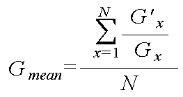
상기 제어블럭은, 상기 각 LED블럭에 대해 초기 출력치와 비교 출력치의 비율인 출력변화율을 산출하는 출력변화율 산출부와, 상기 각 LED블럭의 출력변화율 중 최대값을 추출하고, 상기 각 LED블럭의 출력변화율을 상기 최대값에서 나누어 보상비율을 산출하는 보상비율 산출부를 포함할 수 있다. The control block may include: an output change rate calculating unit configured to calculate an output change rate, which is a ratio of an initial output value and a comparative output value, for each LED block; and extracting a maximum value of the output change rate of each LED block, And a compensation ratio calculator configured to calculate a compensation ratio by dividing the output change rate by the maximum value.

상기 출력변화율은 상기 LED블럭에 포함된 상이한 색상의 R(적)색 LED군, G(녹)색 LED군, B(청)색 LED군에 대해 각각 산출되는 것이 바람직하다. The output change rate is preferably calculated for each of the R (red) LED group, G (green) LED group, B (blue) color LED group of different colors included in the LED block.

상기 제어블럭은, 상기 각 색상 LED군에 대한 출력변화율을 평균하여 색상별로 평균 출력변화율을 각각 산출하는 평균 산출부를 포함할 수 있다. The control block may include an average calculator configured to calculate an average output change rate for each color by averaging the output change rate for each color LED group.

상기 제어블럭은, 색상별 상기 평균 출력변화율과, 상기 각 LED블럭의 각 색상 LED군에 대한 출력변화율 간의 차이에 따라, 상기 각 LED블럭의 상기 각 색상 LED군에 대한 출력 보상이 가능한지 여부를 판단하는 보상 판단부를 더 포함할 수 있다. The control block determines whether output compensation for each color LED group of each LED block is possible according to the difference between the average output change rate for each color and the output change rate for each color LED group of each LED block. The apparatus may further include a compensation determining unit.

상기 보상 판단부는, 상기 차이가 일정 값을 초과하면, 상기 해당 색상 LED군이 손상되거나, 측정에러로 판단하여 상기 보상이 불가능하다고 판단할 수 있다.When the difference exceeds a predetermined value, the compensation determining unit may determine that the compensation is impossible because the corresponding color LED group is damaged or is determined as a measurement error.

상기 보상비율 산출부는, 상기 최대값을 색상에 따라 추출하며, 상기 각 LED블럭의 각 색상 LED군의 출력변화율을 상기 최대값으로 나누어 보상비율을 산출할 수 있다. The compensation ratio calculation unit may extract the maximum value according to color, and calculate a compensation ratio by dividing the output change rate of each color LED group of each LED block by the maximum value.

상기 제어블럭은, 보상이 가능하다고 판단된 상기 각 LED블럭의 각 색상 LED군에 제공되는 펄스신호의 펄스폭을 상기 보상비율에 대응되도록 산출하는 펄스폭 산출부를 더 포함할 수 있다. The control block may further include a pulse width calculator configured to calculate a pulse width of a pulse signal provided to each color LED group of each of the LED blocks determined to be compensated to correspond to the compensation ratio.

상기 각 LED블럭의 각 색상 LED군의 작동을 제어하는 LED 드라이버;를 더 포함하며; 상기 제어블럭은, 상기 산출된 펄스폭에 대한 정보를 상기 LED 드라이버로 제공하고, 상기 LED 드라이버는 상기 펄스폭을 갖는 펄스신호를 상기 각 LED블럭의 각 색상 LED군에 제공할 수 있다. And a LED driver for controlling the operation of each color LED group of each LED block. The control block may provide information about the calculated pulse width to the LED driver, and the LED driver may provide a pulse signal having the pulse width to each color LED group of each LED block.

상기 센서는, 상기 R(적)색 LED군, 상기 G(녹)색 LED군, 상기 B(청)색 LED군의 출력 감지를 위해, R센서, G센서, B센서를 포함하는 것이 바람직하다. Preferably, the sensor includes an R sensor, a G sensor, and a B sensor for output detection of the R (red) LED group, the G (green) LED group, and the B (blue) LED group. .

상기 R센서, 상기 G센서, 상기 B센서는 각각 하나씩 장착될 수 있다. The R sensor, the G sensor, and the B sensor may be mounted one by one.

상기 R센서, 상기 G센서, 상기 B센서는 감도의 조절이 가능한 것이 바람직하다. The R sensor, the G sensor, the B sensor is preferably capable of adjusting the sensitivity.

상기 R센서, 상기 G센서, 상기 B센서는 하나의 센서쌍을 이루며, 복수의 센서쌍이 군집하여 장착될 수 있다. The R sensor, the G sensor, and the B sensor form one sensor pair, and a plurality of sensor pairs may be clustered and mounted.

복수의 상기 R센서, 복수의 상기 G센서, 복수의 상기 B센서는, 동일한 색상의 센서내에서 상호 상이한 감도를 갖는 것이 바람직하다. It is preferable that the plurality of R sensors, the plurality of G sensors, and the plurality of B sensors have mutually different sensitivity in the same color sensor.

상기 R센서, 상기 G센서, 상기 B센서는 하나의 센서쌍을 이루며, 복수의 상 기 센서쌍이 상호 소정 간격을 두고 장착될 수 있다.The R sensor, the G sensor, and the B sensor form one sensor pair, and the plurality of sensor pairs may be mounted at predetermined intervals from each other.

상기 각 센서쌍은 동일한 감도를 갖는 것이 바람직하다.Each sensor pair preferably has the same sensitivity.

상기 각 LED블럭의 초기 출력치 또는 비교 출력치의 감지시, 상기 각 LED블럭을 교번적으로 턴온시켜 상기 각 LED블럭을 하나씩 감지할 수 있다. When the initial output value or the comparative output value of each LED block is detected, each of the LED blocks may be alternately turned on to detect each of the LED blocks one by one.

상기 각 LED블럭의 초기 출력치 또는 비교 출력치의 감지시, 감지순서가 된 상기 LED블럭에 포함된 R색 LED군, G색 LED군, B색 LED군을 교번적으로 턴온시킬 수 있다. When the initial output value or the comparative output value of each LED block is detected, the R-color LED group, the G-color LED group, and the B-color LED group included in the LED blocks in the sensing order may be alternately turned on.

상기 각 LED블럭의 초기 출력치 또는 비교 출력치의 감지시, 감지순서가 된 상기 LED블럭에 포함된 R색 LED군, G색 LED군, B색 LED군을 한꺼번에 턴온시킬 수 있다. Upon detection of the initial output value or the comparative output value of each LED block, the R-color LED group, the G-color LED group, and the B-color LED group included in the LED blocks in the detection order may be turned on at once.

한편, 본 발명의 LED 기반 광시스템의 노화 보상방법은, 소정 갯수의 LED로 이루어진 적어도 하나의 LED블럭에 대해 초기상태에서의 상기 각 LED블럭에 대한 초기 출력치를 생성하는 단계; 비교시점에서 상기 각 LED블럭의 출력치를 감지하여 상기 각 LED블럭에 대한 비교 출력치를 생성하는 단계; 상기 각 LED블럭에 대해 초기 출력치와 비교 출력치간의 차이에 따라 소정의 보상비율을 생성하는 단계; 및, 상기 보상비율에 따라 상기 각 LED블럭의 출력을 보상하는 단계;를 포함하는 것을 특징으로 한다. On the other hand, the aging compensation method of the LED-based optical system of the present invention, generating an initial output value for each of the LED block in the initial state for at least one LED block consisting of a predetermined number of LEDs; Generating a comparison output value for each LED block by sensing an output value of each LED block at a comparison time point; Generating a predetermined compensation ratio for each LED block according to a difference between an initial output value and a comparative output value; And compensating for the output of each LED block according to the compensation ratio.

이하에서는 첨부도면을 참조하여 본 발명을 상세히 설명한다. Hereinafter, the present invention will be described in detail with reference to the accompanying drawings.

도 1은 LED 기반 광시스템의 일 실시예에 따른 백라이트의 구성 블럭도이다. 1 is a block diagram illustrating a backlight according to an embodiment of an LED based optical system.

백라이트는 복수의 LED블럭(10-1~10-N), LED 드라이버(20), RGB 센서(50), 제어블럭(30), 저장부(40)를 포함한다. The backlight includes a plurality of LED blocks 10-1 to 10 -N, an LED driver 20, an RGB sensor 50, a control block 30, and a storage 40.

하나의 백라이트는 복수의 LED블럭(10-1~10-N)으로 형성되며, 각 LED블럭(10-1~10-N)은 다수의 R(Red)색 LED, G(Green)색 LED, B(Blue)색 LED를 포함한다. 여기서, 복수의 R색 LED는 상호 직렬로 연결되어 하나의 R색 LED군(11)을 이루며, 복수의 G색 LED와, 복수의 B색 LED들도 각각 상호 직렬로 연결되어 각각 G색 LED군(12)과 B색 LED군(13)을 형성한다. R색 LED군(11), G색 LED군(12), B색 LED군(13)은 상호 병렬로 연결되어 있으며, 각각 LED 드라이버(20)에 연결되어 펄스신호를 제공받는다. One backlight is formed of a plurality of LED blocks (10-1 to 10-N), each LED block (10-1 to 10-N) is a plurality of R (Red) color LED, G (Green) color LED, Contains B (Blue) color LED. Here, the plurality of R-color LEDs are connected in series to each other to form one R-color LED group 11, and the plurality of G-color LEDs and the plurality of B-color LEDs are also connected in series to each other, respectively, to each G-color LED group 12 and the B-color LED group 13 are formed. The R color LED group 11, the G color LED group 12, and the B color LED group 13 are connected in parallel with each other, and are connected to the LED driver 20 to receive a pulse signal.

LED 드라이버(20)에는, 하나 또는 복수의 LED블럭(10-1~10-N)이 연결되어 있으며, 하나의 백라이트를 형성하는 모든 LED블럭(10-1~10-N)이 연결되어 있을 수도 있고, 그 중 일부의 LED블럭(10)만이 연결되어 있을 수도 있다. LED 드라이버(20)는, 제어블럭(30)으로부터의 제어에 따라, 각 LED블럭(10-1~10-N)의 R색 LED군(11), G색 LED군(12), B색 LED군(13)으로 제공되는 전류량을 결정하는 펄스신호의 펄스폭을 제어한다. 펄스신호의 펄스폭이 넓을수록, 즉 듀티비가 클수록 각 LED군(11,12,13)으로 제공되는 전류량이 증가하게 된다. One or more LED blocks 10-1 to 10 -N are connected to the LED driver 20, and all the LED blocks 10-1 to 10 -N forming one backlight may be connected to the LED driver 20. And, only some of the LED block 10 may be connected. According to the control from the control block 30, the LED driver 20 performs R-color LED group 11, G-color LED group 12, and B-color LED of each LED block 10-1 to 10-N. The pulse width of the pulse signal for determining the amount of current provided to the group 13 is controlled. As the pulse width of the pulse signal is wider, that is, the duty ratio is larger, the amount of current provided to each of the LED groups 11, 12, 13 increases.

RGB센서(50)는 R색 LED군(11), G색 LED군(12), B색 LED군(13)에서 출력되는 에너지를 각각 감지하는 R센서(51), G센서(52), B센서(53)와, 각 센서(51,52,53)로부터 감지된 에너지를 데이터화하여 R색 LED군(11), G색 LED군(12), B색 LED군(13)의 출력치를 생성하는 센서보드(57)를 포함한다. 여기서, 각 센서(51,52,53)는 포토 다이오드로 마련될 수 있다.RGB sensor 50 is R sensor 51, G sensor 52, B for detecting the energy output from the R-color LED group 11, G-color LED group 12, B-color LED group 13, respectively. The sensor 53 and the energy detected from each of the sensors 51, 52, and 53 are dataized to generate output values of the R-color LED group 11, the G-color LED group 12, and the B-color LED group 13. The sensor board 57 is included. Here, each of the sensors 51, 52, and 53 may be provided as a photodiode.

이러한 각 센서(51,52,53)는, 조립의 편의성이나 설계상 이유 등에 따라, 백라이트에 각각 하나씩 장착될 수도 있고, R센서(51), G센서(52), B센서(53)가 쌍을 이루어 복수의 센서쌍(51,52,53)이 상호 소정 간격을 두고 장착될 수도 있으며, 복수의 센서쌍(51,52,53)이 백라이트의 일측에 한꺼번에 장착될 수도 있다.Each of the sensors 51, 52, and 53 may be mounted on the backlight one by one for ease of assembly, design reasons, or the like, and the R sensor 51, the G sensor 52, and the B sensor 53 are paired. The plurality of sensor pairs 51, 52, and 53 may be mounted at predetermined intervals, and the plurality of sensor pairs 51, 52, and 53 may be mounted at one side of the backlight at a time.

도 2(a)에는 6개의 LED블럭(10)으로 형성된 백라이트가 도시되어 있으며, 각 센서(51,52,53)는 상단에 배열된 한 쌍의 LED블럭(10) 사이에 장착되어 있다. 도 2(a)는 센서를 하나로 표시하였으나, 해당 위치에는 하나의 센서쌍(51,52,53)이 장착될 수도 있고, 복수의 센서쌍(51,52,53)이 장착될 수도 있음은 물론이다. In FIG. 2A, a backlight formed of six LED blocks 10 is illustrated, and each sensor 51, 52, 53 is mounted between a pair of LED blocks 10 arranged at the top thereof. 2 (a) shows one sensor, one sensor pair 51, 52, 53 may be mounted at a corresponding position, and a plurality of sensor pairs 51, 52, 53 may be mounted, of course. to be.

하나의 센서쌍(51,52,53)이 장착된 경우, 각 센서쌍(51,52,53)은 상호 상이한 거리에 위치한 각 LED블럭(10)의 출력을 감지해야 하므로, R센서(51), G센서(52), B센서(53) 각각은 감도가 조절되는 센서로 마련하는 것이 바람직하다. 즉, 센서쌍(51,52,53)과 인접하게 배치된 LED블럭(10)의 출력을 감지할 때는 R센서(51), G센서(52), B센서(53)의 감도를 감소시키고, 센서쌍(51,52,53)으로부터 멀리 이격된 LED블럭(10)의 출력을 감지할 때는 R센서(51), G센서(52), B센서(53)의 감도를 증가시킴으로써, 각 LED블럭(10)의 출력을 감지할 수 있다. When one sensor pair 51, 52, 53 is mounted, each sensor pair 51, 52, 53 must sense the output of each LED block 10 located at a different distance from each other, so that the R sensor 51 , Each of the G sensor 52 and the B sensor 53 is preferably provided as a sensor whose sensitivity is adjusted. That is, when sensing the output of the LED block 10 disposed adjacent to the sensor pairs 51, 52, 53, the sensitivity of the R sensor 51, G sensor 52, B sensor 53 is reduced, When sensing the output of the LED block 10 spaced apart from the sensor pairs 51, 52, 53, the respective LED blocks are increased by increasing the sensitivity of the R sensor 51, the G sensor 52, and the B sensor 53. The output of 10 can be detected.

복수의 센서쌍(51,52,53)이 장착된 경우에는, 각 센서쌍(51,52,53)의 감도를 달리 설정하고, 각 LED블럭(10)에 대해 출력을 감지하는 센서쌍(51,52,53)을 대응시킴으로써, 각 LED블럭(10)의 출력을 감지하도록 한다.When a plurality of sensor pairs 51, 52, 53 are mounted, sensor pairs 51 for differently setting the sensitivity of each sensor pair 51, 52, 53 and sensing an output for each LED block 10 are provided. By corresponding to, 52, 53, to detect the output of each LED block 10.

도 2(b)에는 N개의 블럭으로 형성된 백라이트가 도시되어 있으며, 각 센서쌍(51,52,53)은 상호 일정 간격을 두고 장착되어 있다. 이에 따라, 각 센서 쌍(51,52,53)은 인접하게 배치된 하나 또는 그 이상의 LED블럭(10)의 출력을 감지하게 된다. 이 때, 각 센서쌍(51,52,53)과, 측정하고자 하는 각 LED블럭(10)간의 거리는 거의 동일하므로, 각 센서쌍(51,52,53)은 동일한 감도를 갖는 것이 바람직하다. 2 (b) shows a backlight formed of N blocks, and the sensor pairs 51, 52, and 53 are mounted at regular intervals from each other. Accordingly, each sensor pair 51, 52, 53 senses the output of one or more LED blocks 10 arranged adjacently. At this time, since the distance between each sensor pair 51, 52, 53 and each LED block 10 to be measured is almost the same, it is preferable that each sensor pair 51, 52, 53 has the same sensitivity.

한편, 도 2(a) 및 도 2(b)을 참조하여 설명한 각 경우, 즉, 하나의 센서쌍(51,52,53)만 장착하는 경우, 복수의 센서쌍(51,52,53)을 한 곳에 장착하는 경우, 복수의 센서쌍(51,52,53)을 분산하여 장착하는 경우에 상관없이 각 LED블럭(10)의 R색 LED군(11), G색 LED군(12), B색 LED군(13)을 각각 턴온시키거나 한꺼번에 턴온시켜 각 LED블럭(10)의 출력을 감지할 수 있다. Meanwhile, in each case described with reference to FIGS. 2A and 2B, that is, when only one sensor pair 51, 52, 53 is mounted, a plurality of sensor pairs 51, 52, 53 are provided. In the case of mounting in one place, the R-color LED group 11, the G-color LED group 12, B of each LED block 10 regardless of the case in which a plurality of sensor pairs 51, 52, 53 are distributed and mounted. The color LED group 13 may be turned on or turned on at the same time to sense the output of each LED block 10.

즉, 각 LED블럭(10)의 출력을 감지할 때, 각 LED블럭(10) 별로 R색 LED군(11), G색 LED군(12), B색 LED군(13)을 각각 순차적으로 턴온시킴으로써, R센서(51), G센서(52), B센서(53)에서 순차적으로 R색 LED군(11), G색 LED군(12), B색 LED군(13)의 출력을 감지하도록 할 수 있다. 그리고, 하나의 LED블럭(10)에 포함되는 R색 LED군(11), G색 LED군(12), B색 LED군(13)을 한꺼번에 턴온시키어, R센서(51), G센서(52), B센서(53)에서 한번에 R색 LED군(11), G색 LED군(12), B색 LED군(13)의 출력을 감지하도록 할 수도 있다. 후자의 경우, 각 센서(51,52,53)에서 출력을 감지하는데 소요되는 시간이 감소하게 된다. That is, when sensing the output of each LED block 10, each of the LED block 10 to turn on the R color LED group 11, G color LED group 12, B color LED group 13 in sequence Thus, the R sensor 51, the G sensor 52, the B sensor 53 to sequentially detect the output of the R color LED group 11, G color LED group 12, B color LED group 13 can do. Then, the R-color LED group 11, the G-color LED group 12, and the B-color LED group 13 included in one LED block 10 are turned on at once, and the R sensor 51 and the G sensor 52 ), The B sensor 53 may sense the output of the R-color LED group 11, the G-color LED group 12, the B-color LED group 13 at a time. In the latter case, the time required for sensing the output by each sensor 51, 52, 53 is reduced.

제어블럭(30)은, 초기상태에서 RGB센서(50)로부터 감지된 초기 출력치(

Figure 112006069821400-pat00001
,
Figure 112006069821400-pat00002
,
Figure 112006069821400-pat00003
)와, 비교시점에서의 비교 출력치(
Figure 112006069821400-pat00004
,
Figure 112006069821400-pat00005
,
Figure 112006069821400-pat00006
)를 비교하여 소정 의 보상비율을 생성하고, 보상비율에 따라 각 LED블럭(10-1~10-N)에 포함되는 각 색상 LED군(11,12,13)으로 제공되는 전류량을 조절하여 출력을 보상한다. The control block 30, the initial output value detected from the RGB sensor 50 in the initial state (
Figure 112006069821400-pat00001
,
Figure 112006069821400-pat00002
,
Figure 112006069821400-pat00003
) And the comparison output value (
Figure 112006069821400-pat00004
,
Figure 112006069821400-pat00005
,
Figure 112006069821400-pat00006
) To generate a predetermined compensation ratio, and adjust the amount of current provided to each color LED group (11, 12, 13) included in each LED block (10-1 ~ 10-N) according to the compensation ratio and output To compensate.

도 3에 도시된 바와 같이, 제어블럭(30)은, 출력감지 제어부(31), 출력변화율 산출부(32), 평균 산출부(33), 보상 판단부(34), 보상비율 산출부(35), 펄스폭 산출부(36)를 포함한다. As shown in FIG. 3, the control block 30 includes an output sensing control unit 31, an output change rate calculating unit 32, an average calculating unit 33, a compensation determining unit 34, and a compensation ratio calculating unit 35. ), The pulse width calculating section 36 is included.

출력감지 제어부(31)는, 각 LED블럭(10-1~10-N)의 각 색상 LED군(11,12,13)의 출력감지를 제어하고, RGB센서(50)로부터 감지된 각 LED블럭(10-1~10-N)의 각 색상 LED군(11,12,13)에 대한 출력치를 저장부(40)에 저장한다. 이 때, 출력감지 제어부(31)는, 초기 출력치(

Figure 112006069821400-pat00007
,
Figure 112006069821400-pat00008
,
Figure 112006069821400-pat00009
)와 비교 출력치(
Figure 112006069821400-pat00010
,
Figure 112006069821400-pat00011
,
Figure 112006069821400-pat00012
)를 저장부(40)에 저장하며, 초기 출력치(
Figure 112006069821400-pat00013
,
Figure 112006069821400-pat00014
,
Figure 112006069821400-pat00015
)는, 백라이트의 제품검사시 또는 처음 전원인가시 등의 초기상태에서 각 LED블럭(10-1~10-N)의 각 색상 LED군(11,12,13)에 대해 감지된 값이고, 비교 출력치(
Figure 112006069821400-pat00016
,
Figure 112006069821400-pat00017
,
Figure 112006069821400-pat00018
)는, 임의의 비교시점에서 각 LED블럭(10-1~10-N)의 각 색상 LED군(11,12,13)에 대해 RGB센서(50)에서 감지된 값이다. The output detection control unit 31 controls the output detection of each color LED group 11, 12, 13 of each LED block 10-1 to 10 -N, and detects each LED block detected by the RGB sensor 50. The output values for the color LED groups 11, 12, and 13 of (10-1 to 10-N) are stored in the storage unit 40. At this time, the output detection control unit 31 performs the initial output value (
Figure 112006069821400-pat00007
,
Figure 112006069821400-pat00008
,
Figure 112006069821400-pat00009
) And comparison output (
Figure 112006069821400-pat00010
,
Figure 112006069821400-pat00011
,
Figure 112006069821400-pat00012
) Is stored in the storage unit 40, and the initial output value (
Figure 112006069821400-pat00013
,
Figure 112006069821400-pat00014
,
Figure 112006069821400-pat00015
) Is a value detected for each color LED group (11, 12, 13) of each LED block (10-1 ~ 10-N) in the initial state, such as during the product inspection of the backlight or when the power is first applied. Output value (
Figure 112006069821400-pat00016
,
Figure 112006069821400-pat00017
,
Figure 112006069821400-pat00018
) Is a value detected by the RGB sensor 50 for each color LED group 11, 12, 13 of each LED block 10-1 to 10 -N at an arbitrary comparison time point.

저장부(40)는 EEPROM으로 마련될 수도 있고, 플레쉬 메모리(Flash Memory)와 같은 메모리 소자로 마련될 수도 있으며, 초기 출력치(

Figure 112006069821400-pat00019
,
Figure 112006069821400-pat00020
,
Figure 112006069821400-pat00021
)를 저장하는 초기값 저장파트(41)와, 비교 출력치(
Figure 112006069821400-pat00022
,
Figure 112006069821400-pat00023
,
Figure 112006069821400-pat00024
)를 저장하는 비교값 저장파트(42)를 포함한다. 여기서, 초기값 저장파트(41)와 비교값 저장파트(42)는 상이 한 주소를 갖는다. The storage unit 40 may be provided as an EEPROM, or may be provided as a memory device such as a flash memory, and the initial output value (
Figure 112006069821400-pat00019
,
Figure 112006069821400-pat00020
,
Figure 112006069821400-pat00021
) And the comparison output value (
Figure 112006069821400-pat00022
,
Figure 112006069821400-pat00023
,
Figure 112006069821400-pat00024
) And a comparison value storage part 42 for storing (). Here, the initial value storage part 41 and the comparison value storage part 42 have different addresses.

출력감지 제어부(31)는, 도 4를 참조하여 후술하는 바와 같은 과정을 거쳐 저장부(40)의 초기값 저장파트(41)와 비교값 저장파트(42)에 초기 출력치(

Figure 112006069821400-pat00025
,
Figure 112006069821400-pat00026
,
Figure 112006069821400-pat00027
)와 비교 출력치(
Figure 112006069821400-pat00028
,
Figure 112006069821400-pat00029
,
Figure 112006069821400-pat00030
)를 각각 저장한다. The output detection control unit 31 passes the initial output value () to the initial value storage part 41 and the comparison value storage part 42 of the storage unit 40 by the process described below with reference to FIG. 4.
Figure 112006069821400-pat00025
,
Figure 112006069821400-pat00026
,
Figure 112006069821400-pat00027
) And comparison output (
Figure 112006069821400-pat00028
,
Figure 112006069821400-pat00029
,
Figure 112006069821400-pat00030
Save each).

출력변화율 산출부(32)는, 각 LED블럭(10-1~10-N)에 대해 저장부(40)에 저장된 초기 출력치(

Figure 112006069821400-pat00031
,
Figure 112006069821400-pat00032
,
Figure 112006069821400-pat00033
)와 비교 출력치(
Figure 112006069821400-pat00034
,
Figure 112006069821400-pat00035
,
Figure 112006069821400-pat00036
)의 비율인 출력변화율(
Figure 112006069821400-pat00037
,
Figure 112006069821400-pat00038
,
Figure 112006069821400-pat00039
)을 산출하며, 출력변화율(
Figure 112006069821400-pat00040
,
Figure 112006069821400-pat00041
,
Figure 112006069821400-pat00042
)은 초기 출력치(
Figure 112006069821400-pat00043
,
Figure 112006069821400-pat00044
,
Figure 112006069821400-pat00045
)를 비교 출력치(
Figure 112006069821400-pat00046
,
Figure 112006069821400-pat00047
,
Figure 112006069821400-pat00048
)로 나눈 값이다. 이 때, 출력변화율 산출부(32)는, 각 LED블럭(10-1~10-N)에 포함된 상이한 색상의 R색 LED군(11), G색 LED군(12), B색 LED군(13)에 대해 각각 출력변화율(
Figure 112006069821400-pat00049
,
Figure 112006069821400-pat00050
,
Figure 112006069821400-pat00051
)을 산출한다. The output change rate calculation unit 32 includes an initial output value (stored in the storage unit 40 for each of the LED blocks 10-1 to 10-N).
Figure 112006069821400-pat00031
,
Figure 112006069821400-pat00032
,
Figure 112006069821400-pat00033
) And comparison output (
Figure 112006069821400-pat00034
,
Figure 112006069821400-pat00035
,
Figure 112006069821400-pat00036
The rate of change of output, which is the ratio of
Figure 112006069821400-pat00037
,
Figure 112006069821400-pat00038
,
Figure 112006069821400-pat00039
) And output change rate (
Figure 112006069821400-pat00040
,
Figure 112006069821400-pat00041
,
Figure 112006069821400-pat00042
) Is the initial output value (
Figure 112006069821400-pat00043
,
Figure 112006069821400-pat00044
,
Figure 112006069821400-pat00045
) To compare output value (
Figure 112006069821400-pat00046
,
Figure 112006069821400-pat00047
,
Figure 112006069821400-pat00048
Divided by). At this time, the output change rate calculation unit 32 includes the R-color LED group 11, the G-color LED group 12, and the B-color LED group of different colors included in each LED block 10-1 to 10-N. (13) for each output change rate (
Figure 112006069821400-pat00049
,
Figure 112006069821400-pat00050
,
Figure 112006069821400-pat00051
) Is calculated.

이에 따라, N개의 LED블럭(10-1~10-N)에 대해 R색 LED군(11), G색 LED군(12), B색 LED군(13) 각각에 대한 3*N개의 출력변화율(

Figure 112006069821400-pat00052
,
Figure 112006069821400-pat00053
,
Figure 112006069821400-pat00054
)이 생성된다. 여기서, 첫번째 LED블럭(10-1)의 R색 LED군(11)에 대한 출력변화율(
Figure 112006069821400-pat00055
)은 R1'/R1로 표현되고, G색 LED군(12)에 대한 출력변화율(
Figure 112006069821400-pat00056
)은 G1'/G1로 표현되고, B색 LED군(13)에 대한 출력변화율(
Figure 112006069821400-pat00057
)은 B1'/B1로 표현된다. 마찬가지로, N번째 LED블럭(10-N)의 R색 LED군(11)에 대한 출력변화율(
Figure 112006069821400-pat00058
)은 RN'/RN로 표현되고, G색 LED군(12)에 대한 출력변화율(
Figure 112006069821400-pat00059
)은 GN'/GN로 표현되고, B색 LED군(13)에 대한 출력변화율(
Figure 112006069821400-pat00060
)은 BN'/BN로 표현된다.Accordingly, 3 * N output change rates for each of the R-color LED group 11, the G-color LED group 12, and the B-color LED group 13 for the N LED blocks 10-1 to 10-N. (
Figure 112006069821400-pat00052
,
Figure 112006069821400-pat00053
,
Figure 112006069821400-pat00054
) Is generated. Here, the output change rate for the R-color LED group 11 of the first LED block 10-1 (
Figure 112006069821400-pat00055
) Is expressed as R 1 '/ R 1 , and the output change rate (
Figure 112006069821400-pat00056
) Is expressed as G 1 '/ G 1 , and the output change rate (
Figure 112006069821400-pat00057
) Is represented by B 1 '/ B 1 . Similarly, the output change rate of the R-color LED group 11 of the N-th LED block 10-N (
Figure 112006069821400-pat00058
) Is expressed as R N '/ R N , and the output change rate (
Figure 112006069821400-pat00059
) Is expressed as G N '/ G N , and the output change rate (
Figure 112006069821400-pat00060
) Is represented by B N '/ B N.

평균 산출부(33)는, 모든 LED블럭(10-1~10-N)에 포함된 R색 LED군(11), G색 LED군(12), B색 LED군(13)에 대해 각각 출력변화율(

Figure 112006069821400-pat00061
,
Figure 112006069821400-pat00062
,
Figure 112006069821400-pat00063
)을 평균하여 각 색상 LED군(11,12,13)에 대한 평균 출력변화율을 산출한다. 즉, 평균 산출부(33)는, 다음의 수학식 1에 나타난 바와 같이, 모든 LED블럭(10-1~10-N)에 포함된 R색 LED군(11)의 출력변화율(
Figure 112006069821400-pat00064
)을 모두 합산하고, 이를 LED블럭(10-1~10-N)의 수인 N으로 나누어 R색 LED군(11)의 평균 출력변화율(Rmean)을 산출한다. 마찬가지 방법으로 평균 산출부(33), G색 LED군(12)의 평균 출력변화율(Gmean)과, B색 LED군(13)의 평균 출력변화율(Bmean)을 산출한다. 따라서, 평균 산출부(33)에서 산출된 평균 출력변화율(Rmean, Gmean, Bmean)은 각 색상에 대해 1개씩으로 총 3개가 된다. The average calculator 33 outputs the R-color LED group 11, the G-color LED group 12, and the B-color LED group 13 included in all the LED blocks 10-1 to 10-N, respectively. Rate of change
Figure 112006069821400-pat00061
,
Figure 112006069821400-pat00062
,
Figure 112006069821400-pat00063
) Is averaged to calculate the average output change rate for each color LED group (11, 12, 13). That is, the average calculation unit 33, as shown in the following equation 1, the output change rate (R) of the R-color LED group 11 included in all the LED blocks (10-1 ~ 10-N) (
Figure 112006069821400-pat00064
) Are added together and divided by N, which is the number of LED blocks 10-1 to 10-N, to calculate an average output change rate R mean of the R-color LED groups 11. In the same way to calculate the average calculating unit (33), the average output variation rate G (G mean) and, B average output rate (mean B) of the color LED groups (13) of the color LED groups (12). Therefore, the average output change rate (R mean , G mean , B mean ) calculated by the average calculating unit 33 is three in total, one for each color.

Figure 112006069821400-pat00065

Figure 112006069821400-pat00066

Figure 112006069821400-pat00067

보상 판단부(34)는, 수학식 2에 나타난 바와 같이, R, G, B색 LED군(13)의 각 평균 출력변화율(Rmean, Gmean, Bmean)과, 각 LED블럭(10-1~10-N)의 각 색상 LED군(11,12,13)에 대한 출력변화율(

Figure 112006069821400-pat00068
,
Figure 112006069821400-pat00069
,
Figure 112006069821400-pat00070
) 간의 차이를 각 색상에 따라 미리 설정한 보상범위값(FaultRangeR, FaultRangeG, FaultRangeB)과 비교하여, 각 LED블럭(10-1~10-N)의 각 색상 LED군(11,12,13)에 대한 보상이 가능한지 여부를 판단한다. The compensation determination unit 34, as shown in equation (2), each of the average output change rate (R mean , G mean , B mean ) of the R, G, B color LED group 13, and each LED block (10-) Change rate of output for each LED group (11, 12, 13) of 1 ~ 10-N
Figure 112006069821400-pat00068
,
Figure 112006069821400-pat00069
,
Figure 112006069821400-pat00070
) Is compared with the preset compensation range values (FaultRange R , FaultRange G , and FaultRange B ) according to each color, and the LED group (11, 12, It is determined whether the compensation for 13) is possible.

Figure 112006069821400-pat00071

Figure 112006069821400-pat00072

Figure 112006069821400-pat00073

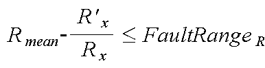
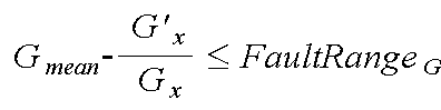
여기서, x는 LED블럭(10-1~10-N)의 번호로서, 수학식 2가 모든 LED블럭(10-1~10-N)의 모든 색상 LED군(11,12,13)에 대해 보상가능여부가 판단된다는 것을 뜻한다. 즉, 3*N개의 색상 LED군(11,12,13)에 대해 보상가능여부가 판단된다. Here, x is the number of the LED blocks 10-1 to 10-N, and Equation 2 compensates for all the color LED groups 11, 12, and 13 of all the LED blocks 10-1 to 10-N. It means that the possibility is judged. That is, it is determined whether the 3 * N color LED groups 11, 12, and 13 can be compensated.

보상 판단부(34)는, 각 LED블럭(10-1~10-N)의 각 색상 LED군(11,12,13)의 출력변화율(

Figure 112006069821400-pat00074
,
Figure 112006069821400-pat00075
,
Figure 112006069821400-pat00076
)과, 각 색상 LED군(11,12,13)의 평균 출력변화율(Rmean, Gmean, Bmean) 간의 차이가 보상범위값을 넘는 경우에는 보상이 불가능하다고 판단하고, 보상범위값내에 포함되는 경우에는 보상이 가능하다고 판단한다. 이는 양자간의 차가 보상범위값보다 크면, 해당 LED블럭(10-1~10-N)의 해당 색상 LED군(11,12,13)에 포함된 LED가 손상되거나 측정상에 에러가 발생한 것으로 간주하기 때문이다. 따라서, 보상범위값은 LED가 손상되거나 측정상 에러가 발생하지 아니한다는 전제하에 산출될 수 있는 평균 출력변화율(Rmean, Gmean, Bmean)과 출력변화율(
Figure 112006069821400-pat00077
,
Figure 112006069821400-pat00078
,
Figure 112006069821400-pat00079
) 간의 차로 설정된다. Compensation determination unit 34, the output change rate of each color LED group (11, 12, 13) of each LED block (10-1 ~ 10-N) (
Figure 112006069821400-pat00074
,
Figure 112006069821400-pat00075
,
Figure 112006069821400-pat00076
) And when the difference between the average output change rate (R mean , G mean , B mean ) of each color LED group (11, 12, 13) exceeds the compensation range value, it is determined that compensation is impossible and included in the compensation range value. If it does, it is determined that compensation is possible. If the difference between them is larger than the compensation range value, it is assumed that the LEDs included in the corresponding color LED groups 11, 12 and 13 of the corresponding LED blocks 10-1 to 10-N are damaged or have an error in measurement. Because. Therefore, the compensation range values are the average output change rate (R mean , G mean , B mean ) and output change rate (which can be calculated under the assumption that the LED is not damaged or no measurement error occurs).
Figure 112006069821400-pat00077
,
Figure 112006069821400-pat00078
,
Figure 112006069821400-pat00079
) Is set.

보상비율 산출부(35)는, 보상이 가능하다고 판단된 LED블럭(10-1~10-N)의 각 색상 LED군(11,12,13)에 대해 보상비율(

Figure 112006069821400-pat00080
,
Figure 112006069821400-pat00081
,
Figure 112006069821400-pat00082
)을 산출한다. 이를 위해, 보상 비율 산출부(35)는, 수학식 3에 나타난 바와 같이, LED블럭(10-1~10-N)의 각 색상 LED군(11,12,13)에 대한 출력변화율(
Figure 112006069821400-pat00083
,
Figure 112006069821400-pat00084
,
Figure 112006069821400-pat00085
) 중 최대값(
Figure 112006069821400-pat00086
,
Figure 112006069821400-pat00087
,
Figure 112006069821400-pat00088
)을 추출하고, 최대값(
Figure 112006069821400-pat00089
,
Figure 112006069821400-pat00090
,
Figure 112006069821400-pat00091
)을 각 LED블럭(10-1~10-N)의 각 색상 LED군(11,12,13)의 출력변화율(
Figure 112006069821400-pat00092
,
Figure 112006069821400-pat00093
,
Figure 112006069821400-pat00094
)로 나누어 보상비율(
Figure 112006069821400-pat00095
,
Figure 112006069821400-pat00096
,
Figure 112006069821400-pat00097
)을 산출한다. The compensation ratio calculator 35 calculates a compensation ratio (for each color LED group 11, 12, 13 of the LED blocks 10-1 to 10 -N that are determined to be compensated).
Figure 112006069821400-pat00080
,
Figure 112006069821400-pat00081
,
Figure 112006069821400-pat00082
) Is calculated. To this end, the compensation ratio calculation unit 35, as shown in the equation (3), the output change rate for each color LED group (11, 12, 13) of the LED blocks (10-1 ~ 10-N) (
Figure 112006069821400-pat00083
,
Figure 112006069821400-pat00084
,
Figure 112006069821400-pat00085
Of ()
Figure 112006069821400-pat00086
,
Figure 112006069821400-pat00087
,
Figure 112006069821400-pat00088
), And the maximum value (
Figure 112006069821400-pat00089
,
Figure 112006069821400-pat00090
,
Figure 112006069821400-pat00091
) Is the change rate of the output of each LED group (11, 12, 13) of each LED block (10-1 ~ 10-N)
Figure 112006069821400-pat00092
,
Figure 112006069821400-pat00093
,
Figure 112006069821400-pat00094
) Divided by)
Figure 112006069821400-pat00095
,
Figure 112006069821400-pat00096
,
Figure 112006069821400-pat00097
) Is calculated.

Figure 112006069821400-pat00098

Figure 112006069821400-pat00099

Figure 112006069821400-pat00100

여기서, 보상비율(

Figure 112006069821400-pat00101
,
Figure 112006069821400-pat00102
,
Figure 112006069821400-pat00103
)은 각 LED블럭(10-1~10-N) 간의 상대적인 출력변화율(
Figure 112006069821400-pat00104
,
Figure 112006069821400-pat00105
,
Figure 112006069821400-pat00106
)의 비율을 나타내며, 출력변화율(
Figure 112006069821400-pat00107
,
Figure 112006069821400-pat00108
,
Figure 112006069821400-pat00109
)을 최대값(
Figure 112006069821400-pat00110
,
Figure 112006069821400-pat00111
,
Figure 112006069821400-pat00112
)으로 나누었으므로, 1보다 작거나 같은 값을 갖게 된다. 따라서, 출력변화율(
Figure 112006069821400-pat00113
,
Figure 112006069821400-pat00114
,
Figure 112006069821400-pat00115
)이 최대값(
Figure 112006069821400-pat00116
,
Figure 112006069821400-pat00117
,
Figure 112006069821400-pat00118
)과 동일한 LED블럭(10-1~10-N)의 해당 색상 LED군(11,12,13)은, 보상비율(
Figure 112006069821400-pat00119
,
Figure 112006069821400-pat00120
,
Figure 112006069821400-pat00121
)이 1이 되며, 출력변화율(
Figure 112006069821400-pat00122
,
Figure 112006069821400-pat00123
,
Figure 112006069821400-pat00124
)이 최대값(
Figure 112006069821400-pat00125
,
Figure 112006069821400-pat00126
,
Figure 112006069821400-pat00127
)보다 작은 LED블럭(10-1~10-N)의 해당 색상 LED군(11,12,13)은 보상비율(
Figure 112006069821400-pat00128
,
Figure 112006069821400-pat00129
,
Figure 112006069821400-pat00130
)은 1보다 작게 된다. Where compensation ratio (
Figure 112006069821400-pat00101
,
Figure 112006069821400-pat00102
,
Figure 112006069821400-pat00103
) Is the relative output change rate between each LED block (10-1 ~ 10-N)
Figure 112006069821400-pat00104
,
Figure 112006069821400-pat00105
,
Figure 112006069821400-pat00106
) And the rate of change of output (
Figure 112006069821400-pat00107
,
Figure 112006069821400-pat00108
,
Figure 112006069821400-pat00109
) To the maximum value (
Figure 112006069821400-pat00110
,
Figure 112006069821400-pat00111
,
Figure 112006069821400-pat00112
Divided by), so it will have a value less than or equal to 1. Therefore, the output change rate (
Figure 112006069821400-pat00113
,
Figure 112006069821400-pat00114
,
Figure 112006069821400-pat00115
) Is the maximum value (
Figure 112006069821400-pat00116
,
Figure 112006069821400-pat00117
,
Figure 112006069821400-pat00118
), The corresponding LED group (11, 12, 13) of the same LED block (10-1 ~ 10-N), the compensation ratio (
Figure 112006069821400-pat00119
,
Figure 112006069821400-pat00120
,
Figure 112006069821400-pat00121
) Becomes 1, and the output change rate (
Figure 112006069821400-pat00122
,
Figure 112006069821400-pat00123
,
Figure 112006069821400-pat00124
) Is the maximum value (
Figure 112006069821400-pat00125
,
Figure 112006069821400-pat00126
,
Figure 112006069821400-pat00127
Corresponding color LED group (11, 12, 13) of LED block (10-1 ~ 10-N) smaller than
Figure 112006069821400-pat00128
,
Figure 112006069821400-pat00129
,
Figure 112006069821400-pat00130
) Becomes smaller than one.

이 때, 보상비율(

Figure 112006069821400-pat00131
,
Figure 112006069821400-pat00132
,
Figure 112006069821400-pat00133
)이 1인 LED블럭(10-1~10-N)의 해당 색상 LED군(11,12,13)에는 타 LED블럭(10-1~10-N)보다 많은 전류량이 제공되어야 한다. 그러나, 각 LED에 제공되는 전류량은 LED의 특성에 따라 임계치가 정해져 있으므로 무한정 전류량을 증가시킬 수 없고, 보상이 가능한 LED블럭(10-1~10-N)의 해당 색상 LED군(11,12,13)의 전류량을 전반적으로 증가시킬 경우, LED의 수명을 저하시키고 전력소모가 커지게 된다. At this time, the compensation ratio (
Figure 112006069821400-pat00131
,
Figure 112006069821400-pat00132
,
Figure 112006069821400-pat00133
Corresponding color LED groups 11, 12, and 13 of LED blocks 10-1 to 10-N having 1) should be provided with a larger amount of current than other LED blocks 10-1 to 10-N. However, since the amount of current provided to each LED has a threshold value determined according to the characteristics of the LED, it is impossible to increase the amount of current indefinitely, and the corresponding color LED group 11, 12, Increasing the amount of current in 13) will reduce the life of LED and increase power consumption.

따라서, 보상비율(

Figure 112006069821400-pat00134
,
Figure 112006069821400-pat00135
,
Figure 112006069821400-pat00136
)이 1인 LED블럭(10-1~10-N)의 해당 색상 LED군(11,12,13)에 대해서는, 보상을 수행하지 아니하고, 즉, 종래와 동일한 전류량을 공급하여야 한다. 반면, 보상비율(
Figure 112006069821400-pat00137
,
Figure 112006069821400-pat00138
,
Figure 112006069821400-pat00139
)이 1보다 작은 LED블럭(10-1~10-N)의 해당 색상 LED군(11,12,13)에 대해서는 보상이 수행되어 종래보다 작은 전류량이 공급되어야 한다. Therefore, the compensation ratio (
Figure 112006069821400-pat00134
,
Figure 112006069821400-pat00135
,
Figure 112006069821400-pat00136
For the corresponding color LED groups 11, 12, and 13 of the LED blocks 10-1 to 10-N having 1), compensation is not performed, that is, the same amount of current as before should be supplied. On the other hand, the compensation ratio (
Figure 112006069821400-pat00137
,
Figure 112006069821400-pat00138
,
Figure 112006069821400-pat00139
Compensation is performed on the corresponding color LED groups 11, 12, and 13 of the LED blocks 10-1 to 10-N having a smaller than 1 to supply a smaller amount of current than the conventional art.

펄스폭 산출부(36)는, 수학식 4에 따라, 보상비율(

Figure 112006069821400-pat00140
,
Figure 112006069821400-pat00141
,
Figure 112006069821400-pat00142
)을 갖는 LED 블럭(10-1~10-N)의 해당 색상 LED군(11,12,13)에 제공되는 펄스신호의 펄스폭을 산출한다. The pulse width calculator 36 calculates a compensation ratio (
Figure 112006069821400-pat00140
,
Figure 112006069821400-pat00141
,
Figure 112006069821400-pat00142
The pulse widths of the pulse signals provided to the corresponding color LED groups 11, 12, and 13 of the LED blocks 10-1 to 10-N having the?

Figure 112006069821400-pat00143

Figure 112006069821400-pat00144

Figure 112006069821400-pat00145

여기서, PWMR, PWMG, PWMB는 기존에 각 LED블럭(10-1~10-N)의 각 색상 LED군(11,12,13)에 제공되던 펄스신호의 펄스폭이고, PWMRx, PWMGx, PWMBx는 보상된 펄스신호의 펄스폭이다. Here, PWMR, PWMG, PWMB is the pulse width of the pulse signal provided to each color LED group (11, 12, 13) of each LED block (10-1 ~ 10-N), PWMR x , PWMG x , PWMB x is the pulse width of the compensated pulse signal.

이 때, 보상비율 산출부(35)에서 산출된 보상비율(

Figure 112006069821400-pat00146
,
Figure 112006069821400-pat00147
,
Figure 112006069821400-pat00148
)이 1보다 작은 경우에만 펄스신호의 펄스폭을 산출하며, 보상비율(
Figure 112006069821400-pat00149
,
Figure 112006069821400-pat00150
,
Figure 112006069821400-pat00151
)이 1보다 작기 때문에 펄스신호의 펄스폭은 기존에 비해 작아지게 된다. 즉, 출력변화율(
Figure 112006069821400-pat00152
,
Figure 112006069821400-pat00153
,
Figure 112006069821400-pat00154
)이 최대값(
Figure 112006069821400-pat00155
,
Figure 112006069821400-pat00156
,
Figure 112006069821400-pat00157
)에 도달하여 보상비율(
Figure 112006069821400-pat00158
,
Figure 112006069821400-pat00159
,
Figure 112006069821400-pat00160
)이 1인 LED블럭(10-1~10-N)의 해당 색상 LED군(11,12,13)의 경우에는 기존과 동일한 펄스폭을 갖는 펄스신호가 제공되며, 출력변화율(
Figure 112006069821400-pat00161
,
Figure 112006069821400-pat00162
,
Figure 112006069821400-pat00163
)이 최대값(
Figure 112006069821400-pat00164
,
Figure 112006069821400-pat00165
,
Figure 112006069821400-pat00166
)보다 작아서 보상비 율(
Figure 112006069821400-pat00167
,
Figure 112006069821400-pat00168
,
Figure 112006069821400-pat00169
)이 1보다 작은 LED블럭(10-1~10-N)의 해당 색상 LED군(11,12,13)의 경우에는 기존보다 좁은 펄스폭을 갖는 펄스신호가 제공된다. 결과적으로 노화가 가장 많이 이루어진 LED블럭(10-1~10-N)의 해당 색상 LED군(11,12,13)의 경우에는 기존과 동일한 전류량이 제공되고, 노화가 덜된 LED블럭(10-1~10-N)의 해당 색상 LED군(11,12,13)의 경우에는 기존보다 적은 전류량이 제공된다. At this time, the compensation ratio calculated by the compensation ratio calculation unit 35 (
Figure 112006069821400-pat00146
,
Figure 112006069821400-pat00147
,
Figure 112006069821400-pat00148
The pulse width of the pulse signal is calculated only when) is less than 1, and the compensation ratio (
Figure 112006069821400-pat00149
,
Figure 112006069821400-pat00150
,
Figure 112006069821400-pat00151
Since) is smaller than 1, the pulse width of the pulse signal is smaller than before. That is, output change rate (
Figure 112006069821400-pat00152
,
Figure 112006069821400-pat00153
,
Figure 112006069821400-pat00154
) Is the maximum value (
Figure 112006069821400-pat00155
,
Figure 112006069821400-pat00156
,
Figure 112006069821400-pat00157
) To the reward percentage (
Figure 112006069821400-pat00158
,
Figure 112006069821400-pat00159
,
Figure 112006069821400-pat00160
In the case of the corresponding color LED group (11, 12, 13) of the LED block (10-1 ~ 10-N) of 1) is provided with a pulse signal having the same pulse width as the existing,
Figure 112006069821400-pat00161
,
Figure 112006069821400-pat00162
,
Figure 112006069821400-pat00163
) Is the maximum value (
Figure 112006069821400-pat00164
,
Figure 112006069821400-pat00165
,
Figure 112006069821400-pat00166
Less than)
Figure 112006069821400-pat00167
,
Figure 112006069821400-pat00168
,
Figure 112006069821400-pat00169
In the case of the corresponding color LED group (11, 12, 13) of the LED block (10-1 ~ 10-N) is smaller than 1 is provided a pulse signal having a narrower pulse width than conventional. As a result, in the corresponding color LED group (11, 12, 13) of the most aging LED block (10-1 ~ 10-N) is provided the same amount of current as before, LED block (10-1) less aging In the case of the corresponding color LED groups 11, 12 and 13 of ˜10-N), a smaller amount of current is provided.

이에 따라, 노화의 정도에 따라 각 LED블럭(10-1~10-N)의 해당 색상 LED군(11,12,13)에 제공되는 전류량이 변화하여 노화에 따른 각 LED블럭(10-1~10-N)간의 불균일을 보상할 수 있게 된다. Accordingly, according to the degree of aging, the amount of current provided to the corresponding color LED groups 11, 12, and 13 of each of the LED blocks 10-1 to 10-N changes so that each LED block 10-1 to 10-N) non-uniformity can be compensated.

한편, 이러한 보상과정에서 가장 노화가 많이된 LED블럭(10-1~10-N)의 해당 색상 LED군(11,12,13)을 기준으로 백라이트의 밝기가 조정되므로, 전체적으로 백라이트의 밝기가 어두워질 수 있다. 이러한 밝기의 감소는 기존에 모니터 등에서 사용하고 있는 밝기 조절 기능을 이용하여 조절할 수 있다. On the other hand, since the brightness of the backlight is adjusted based on the corresponding color LED group (11, 12, 13) of the most aged LED block (10-1 ~ 10-N) in the compensation process, the brightness of the backlight is dark overall Can lose. This decrease in brightness can be controlled using the brightness control function used in the existing monitors.

펄스폭 산출부(36)는, 산출된 펄스신호의 펄스폭을 LED 드라이버(20)로 제공하고, LED 드라이버(20)에서는 산출된 펄스폭을 가진 펄스신호를 해당 LED군(11,12,13)의 해당 색상 LED군(11,12,13)으로 제공한다. The pulse width calculating unit 36 provides the pulse width of the calculated pulse signal to the LED driver 20, and the LED driver 20 supplies the pulse signal having the calculated pulse width to the corresponding LED group 11, 12, 13. ) To the corresponding color LED group (11, 12, 13).

도 4은 도 3의 출력감지 제어부에서 초기 출력치(

Figure 112006069821400-pat00170
,
Figure 112006069821400-pat00171
,
Figure 112006069821400-pat00172
)와 비교 출력치(
Figure 112006069821400-pat00173
,
Figure 112006069821400-pat00174
,
Figure 112006069821400-pat00175
)를 추출하는 과정을 보인 흐름도이다. 4 is an initial output value of the output detection controller of FIG.
Figure 112006069821400-pat00170
,
Figure 112006069821400-pat00171
,
Figure 112006069821400-pat00172
) And comparison output (
Figure 112006069821400-pat00173
,
Figure 112006069821400-pat00174
,
Figure 112006069821400-pat00175
Is a flow chart showing the process of extracting.

먼저, 출력감지 제어부(31)는 저장부(40)의 초기값 저장파트(41)와 비교값 저장파트(42)의 마커를 체크하고(S301), 초기 출력치(

Figure 112006069821400-pat00176
,
Figure 112006069821400-pat00177
,
Figure 112006069821400-pat00178
)가 저장되어 있는지 확인한다(S302). First, the output detection control unit 31 checks the markers of the initial value storage part 41 and the comparison value storage part 42 of the storage unit 40 (S301), and the initial output value (
Figure 112006069821400-pat00176
,
Figure 112006069821400-pat00177
,
Figure 112006069821400-pat00178
) Is stored (S302).

초기값 저장파트(41)에 초기 출력치(

Figure 112006069821400-pat00179
,
Figure 112006069821400-pat00180
,
Figure 112006069821400-pat00181
)가 저장되어 있지 아니한 경우(S302-N), 출력감지 제어부(31)는 초기값 저장파트(41)의 주소를 정렬한다(S303). 주소 정렬은 초기상태에서 RGB센서(50)로부터 측정된 초기 출력치(
Figure 112006069821400-pat00182
,
Figure 112006069821400-pat00183
,
Figure 112006069821400-pat00184
)를 저장할 수 있도록 하기 위한 것이다. Initial output value to initial value storage part 41
Figure 112006069821400-pat00179
,
Figure 112006069821400-pat00180
,
Figure 112006069821400-pat00181
) Is not stored (S302-N), the output detection control unit 31 sorts the addresses of the initial value storage part 41 (S303). The address alignment is the initial output value measured from the RGB sensor 50 in the initial state.
Figure 112006069821400-pat00182
,
Figure 112006069821400-pat00183
,
Figure 112006069821400-pat00184
) So that it can be saved.

그런 다음, 모든 LED블럭(10-1~10-N)에 제공되는 전원을 턴오프하여 전류를 차단하고(S306), 각 LED블럭(10-1~10-N)의 전원을 하나씩 교번적으로 턴온시킨다(S307). 그리고, 턴온된 LED블럭(10-1~10-N)에 대해, RGB센서(50)를 이용하여 해당 LED블럭(10-1)의 각 색상 LED군(11,12,13)에 대한 초기 출력치(

Figure 112006069821400-pat00185
,
Figure 112006069821400-pat00186
,
Figure 112006069821400-pat00187
)를 측정한다(S308). 출력감지 제어부(31)는, 마지막 LED블럭(10-N)까지 초기 출력치(
Figure 112006069821400-pat00188
,
Figure 112006069821400-pat00189
,
Figure 112006069821400-pat00190
)가 측정되었는지 확인하고(S309), 모든 LED블럭(10-1~10-N)에 대해 초기 출력치(
Figure 112006069821400-pat00191
,
Figure 112006069821400-pat00192
,
Figure 112006069821400-pat00193
)가 측정되면 측정된 각 LED블럭(10-1~10-N)의 초기 출력치(
Figure 112006069821400-pat00194
,
Figure 112006069821400-pat00195
,
Figure 112006069821400-pat00196
)를 저장부(40)의 초기값 저장파트(41)에 저장한다(S310). Then, the current is cut off by turning off the power provided to all the LED blocks 10-1 to 10-N (S306), and the power of each LED block 10-1 to 10-N alternately one by one. Turn on (S307). For the turned-on LED blocks 10-1 to 10 -N, an initial output of each color LED group 11, 12, 13 of the corresponding LED block 10-1 using the RGB sensor 50 is performed. Chi (
Figure 112006069821400-pat00185
,
Figure 112006069821400-pat00186
,
Figure 112006069821400-pat00187
) Is measured (S308). The output detection control unit 31 has the initial output value (the last LED block 10-N).
Figure 112006069821400-pat00188
,
Figure 112006069821400-pat00189
,
Figure 112006069821400-pat00190
) Is measured (S309), the initial output value for all LED blocks (10-1 ~ 10-N) (
Figure 112006069821400-pat00191
,
Figure 112006069821400-pat00192
,
Figure 112006069821400-pat00193
) Is measured, the initial output value of each measured LED block (10-1 ~ 10-N)
Figure 112006069821400-pat00194
,
Figure 112006069821400-pat00195
,
Figure 112006069821400-pat00196
) Is stored in the initial value storage part 41 of the storage unit 40 (S310).

한편, S302단계에서, 초기 출력치(

Figure 112006069821400-pat00197
,
Figure 112006069821400-pat00198
,
Figure 112006069821400-pat00199
)가 저장되어 있는 경 우(S302-Y), 출력감지 제어부(31)는 비교값 저장파트(42)의 주소를 정렬시킨다(S304). 그런 다음, 출력감지 제어부(31)는 LED블럭(10-1~10-N)간의 출력 불균일을 보상할 비교시점이 도래하였는지를 판단한다(S305). On the other hand, in step S302, the initial output value (
Figure 112006069821400-pat00197
,
Figure 112006069821400-pat00198
,
Figure 112006069821400-pat00199
) Is stored (S302-Y), the output detection control unit 31 aligns the address of the comparison value storage part 42 (S304). Then, the output detection control unit 31 determines whether the comparison time point to compensate for the output unevenness between the LED blocks 10-1 to 10-N has arrived (S305).

비교시점이 도래하였으면(S305-Y), 출력감지 제어부(31)는 모든 LED블럭(10-1~10-N)의 전원을 턴오프시키고(S306), 각 LED블럭(10-1~10-N)을 하나씩 교번적으로 턴온시킨다(S307). 그리고 턴온된 LED블럭(10-1~10-N)에 대해, 각 색상 LED군(11,12,13)에 대한 비교 출력치(

Figure 112006069821400-pat00200
,
Figure 112006069821400-pat00201
,
Figure 112006069821400-pat00202
)를 측정한다(S308). When the comparison point has arrived (S305-Y), the output detection control unit 31 turns off the power of all the LED blocks 10-1 to 10-N (S306), and each LED block 10-1 to 10-. N) turns on one by one (S307). For the turned-on LED blocks 10-1 to 10-N, the comparative output values for the respective LED groups 11, 12, and 13 (
Figure 112006069821400-pat00200
,
Figure 112006069821400-pat00201
,
Figure 112006069821400-pat00202
) Is measured (S308).

이 때, 각 LED블럭(10-1~10-N)의 모든 색상 LED군(11,12,13)을 한꺼번에 턴온시켜 백색광이 형성된 상태에서, 각 색상 LED군(11,12,13)에 대한 비교 출력치(

Figure 112006069821400-pat00203
,
Figure 112006069821400-pat00204
,
Figure 112006069821400-pat00205
)를 측정할 수도 있음은 물론이다. At this time, all the color LED group (11, 12, 13) of each LED block (10-1 ~ 10-N) is turned on at the same time to form a white light, for each color LED group (11, 12, 13) Comparative output value
Figure 112006069821400-pat00203
,
Figure 112006069821400-pat00204
,
Figure 112006069821400-pat00205
) Can also be measured.

모든 LED블럭(10-1~10-N)에 대해 비교 출력치(

Figure 112006069821400-pat00206
,
Figure 112006069821400-pat00207
,
Figure 112006069821400-pat00208
)가 측정되면(S309), 측정된 각 LED블럭(10-1~10-N)의 비교 출력치(
Figure 112006069821400-pat00209
,
Figure 112006069821400-pat00210
,
Figure 112006069821400-pat00211
)는 저장부(40)의 비교값 저장파트(42)에 저장된다(S310). Comparison output value for all LED blocks (10-1 ~ 10-N)
Figure 112006069821400-pat00206
,
Figure 112006069821400-pat00207
,
Figure 112006069821400-pat00208
) Is measured (S309), the comparative output value of each measured LED block (10-1 ~ 10-N) (
Figure 112006069821400-pat00209
,
Figure 112006069821400-pat00210
,
Figure 112006069821400-pat00211
) Is stored in the comparison value storage part 42 of the storage unit 40 (S310).

이러한 비교 출력치(

Figure 112006069821400-pat00212
,
Figure 112006069821400-pat00213
,
Figure 112006069821400-pat00214
)를 측정하는 비교시점은, 백라이트를 턴온시킬 때마다, 또는 백라이트의 턴온시간이 일정 시간 이상 경과할 때마다 등 다양하게 설정될 수 있으며, 비교시점은 사용자에 의해 임의로 선택될 수도 있다. 그리고 최초의 비교 출력치(
Figure 112006069821400-pat00215
,
Figure 112006069821400-pat00216
,
Figure 112006069821400-pat00217
) 측정 이후, 다시 비교 출력 치(
Figure 112006069821400-pat00218
,
Figure 112006069821400-pat00219
,
Figure 112006069821400-pat00220
)를 측정하는 경우에는, 상술한 S305 내지 S310 과정을 반복한다. These comparison outputs (
Figure 112006069821400-pat00212
,
Figure 112006069821400-pat00213
,
Figure 112006069821400-pat00214
) Can be variously set each time the backlight is turned on or when the backlight's turn-on time elapses for a predetermined time. The comparison time can be arbitrarily selected by the user. And the first comparison output (
Figure 112006069821400-pat00215
,
Figure 112006069821400-pat00216
,
Figure 112006069821400-pat00217
After measurement, compare output value (
Figure 112006069821400-pat00218
,
Figure 112006069821400-pat00219
,
Figure 112006069821400-pat00220
) Is measured, the above-described process S305 to S310 are repeated.

도 5를 참조하여 LED 백라이트의 노화 보상과정을 설명하면 다음과 같다. Referring to Figure 5 describes the aging compensation process of the LED backlight as follows.

먼저, 도 4에 도시된 바와 같이, 출력감지 제어부(31)는, RGB센서(50)를 이용하여 각 LED블럭(10-1~10-N)의 각 색상 LED군(11,12,13)에 대한 초기 출력치(

Figure 112006069821400-pat00221
,
Figure 112006069821400-pat00222
,
Figure 112006069821400-pat00223
)를 감지하고, 감지된 초기 출력치(
Figure 112006069821400-pat00224
,
Figure 112006069821400-pat00225
,
Figure 112006069821400-pat00226
)를 저장부(40)의 초기값 저장파트(41)에 저장한다. 그리고 노화 보상과정을 수행하여야 하는 시점이 도래하면, 출력감지 제어부(31)는 각 LED블럭(10-1~10-N)의 각 색상 LED군(11,12,13)에 대해 비교 출력치(
Figure 112006069821400-pat00227
,
Figure 112006069821400-pat00228
,
Figure 112006069821400-pat00229
)를 감지하여 저장부(40)의 비교값 저장파트(42)에 저장한다(S401). First, as shown in FIG. 4, the output detection control unit 31 uses the RGB sensor 50 to display each color LED group 11, 12, 13 of each LED block 10-1 to 10 -N. Initial output for
Figure 112006069821400-pat00221
,
Figure 112006069821400-pat00222
,
Figure 112006069821400-pat00223
), And the detected initial output value (
Figure 112006069821400-pat00224
,
Figure 112006069821400-pat00225
,
Figure 112006069821400-pat00226
) Is stored in the initial value storage part 41 of the storage unit 40. When the time point at which the aging compensation process is to be performed arrives, the output detection control unit 31 compares the output values of the respective color LED groups 11, 12, and 13 of the LED blocks 10-1 to 10 -N.
Figure 112006069821400-pat00227
,
Figure 112006069821400-pat00228
,
Figure 112006069821400-pat00229
) Is detected and stored in the comparison value storage part 42 of the storage unit 40 (S401).

그런 다음, 출력변화율 산출부(32)는 저장부(40)의 초기값 저장파트(41)와 비교값 저장파트(42)로부터 초기 출력치(

Figure 112006069821400-pat00230
,
Figure 112006069821400-pat00231
,
Figure 112006069821400-pat00232
)와 비교 출력치(
Figure 112006069821400-pat00233
,
Figure 112006069821400-pat00234
,
Figure 112006069821400-pat00235
)를 인출하고(S402), 인출된 초기 출력치(
Figure 112006069821400-pat00236
,
Figure 112006069821400-pat00237
,
Figure 112006069821400-pat00238
)와 비교 출력치(
Figure 112006069821400-pat00239
,
Figure 112006069821400-pat00240
,
Figure 112006069821400-pat00241
)를 이용하여 각 LED블럭(10-1~10-N)의 각 색상 LED군(11,12,13)에 대해 출력변화율(
Figure 112006069821400-pat00242
,
Figure 112006069821400-pat00243
,
Figure 112006069821400-pat00244
)을 산출한다(S403). 그러면, 평균 산출부(33)에서는, 수학식 1을 이용하여 각 색상 LED군(11,12,13)에 대해 평균 출력변화율(Rmean, Gmean, Bmean)을 산출한다(S404). Then, the output change rate calculator 32 calculates the initial output value from the initial value storage part 41 and the comparison value storage part 42 of the storage part 40.
Figure 112006069821400-pat00230
,
Figure 112006069821400-pat00231
,
Figure 112006069821400-pat00232
) And comparison output (
Figure 112006069821400-pat00233
,
Figure 112006069821400-pat00234
,
Figure 112006069821400-pat00235
) And withdraw the initial output value (
Figure 112006069821400-pat00236
,
Figure 112006069821400-pat00237
,
Figure 112006069821400-pat00238
) And comparison output (
Figure 112006069821400-pat00239
,
Figure 112006069821400-pat00240
,
Figure 112006069821400-pat00241
), The change rate of output for each color LED group (11, 12, 13) of each LED block (10-1 ~ 10-N)
Figure 112006069821400-pat00242
,
Figure 112006069821400-pat00243
,
Figure 112006069821400-pat00244
) Is calculated (S403). Then, the average calculating unit 33 calculates the average output change rate R mean , G mean , B mean for each color LED group 11, 12, 13 using Equation 1 (S404).

이렇게 산출된 출력변화율(

Figure 112006069821400-pat00245
,
Figure 112006069821400-pat00246
,
Figure 112006069821400-pat00247
)과 평균 출력변화율(Rmean, Gmean, Bmean)이 산출되면, 보상 판단부(34)는, 수학식 2를 이용하여 각 LED블럭(10-1~10-N)의 각 색상 LED군(11,12,13)에 대해 보상이 가능한지 여부를 판단한다(S405). 이 때, 미리 설정된 보상범위값을 초과하는 LED블럭(10-1~10-N)의 해당 색상 LED군(11,12,13)에 대해서는 보상이 이루어지지 아니하고 보상과정을 종료한다(S405-N). The output change rate thus calculated (
Figure 112006069821400-pat00245
,
Figure 112006069821400-pat00246
,
Figure 112006069821400-pat00247
) And the average output change rate (R mean , G mean , B mean ) are calculated, the compensation determination unit 34, using the equation (2) of each color LED group of each LED block (10-1 ~ 10-N) It is determined whether compensation is possible for (11, 12, 13) (S405). At this time, the compensation process is not performed for the corresponding color LED groups 11, 12, and 13 of the LED blocks 10-1 to 10-N exceeding the preset compensation range value (S405-N). ).

보상이 가능하다고 판단된 LED블럭(10-1~10-N)의 해당 색상 LED군(11,12,13)에 대한 보상비율(

Figure 112006069821400-pat00248
,
Figure 112006069821400-pat00249
,
Figure 112006069821400-pat00250
)을 결정하기 위해, 보상비율 산출부(35)는, 출력변화율(
Figure 112006069821400-pat00251
,
Figure 112006069821400-pat00252
,
Figure 112006069821400-pat00253
) 중 각 색상에 따라 최대값(
Figure 112006069821400-pat00254
,
Figure 112006069821400-pat00255
,
Figure 112006069821400-pat00256
)을 추출하고(S406), 수학식 3을 이용하여 추출된 최대값(
Figure 112006069821400-pat00257
,
Figure 112006069821400-pat00258
,
Figure 112006069821400-pat00259
)과 출력변화율(
Figure 112006069821400-pat00260
,
Figure 112006069821400-pat00261
,
Figure 112006069821400-pat00262
)간의 비율을 각 LED블럭(10-1~10-N)의 해당 색상 LED군(11,12,13)에 대한 보상비율(
Figure 112006069821400-pat00263
,
Figure 112006069821400-pat00264
,
Figure 112006069821400-pat00265
)로 산출한다(S407). Compensation ratio of the corresponding LED group (11, 12, 13) of the LED block (10-1 ~ 10-N) that is determined to be compensated (
Figure 112006069821400-pat00248
,
Figure 112006069821400-pat00249
,
Figure 112006069821400-pat00250
In order to determine), the compensation ratio calculator 35 calculates an output change rate (
Figure 112006069821400-pat00251
,
Figure 112006069821400-pat00252
,
Figure 112006069821400-pat00253
) Depending on each color
Figure 112006069821400-pat00254
,
Figure 112006069821400-pat00255
,
Figure 112006069821400-pat00256
) Is extracted (S406), and the maximum value extracted using Equation 3 (
Figure 112006069821400-pat00257
,
Figure 112006069821400-pat00258
,
Figure 112006069821400-pat00259
) And output change rate (
Figure 112006069821400-pat00260
,
Figure 112006069821400-pat00261
,
Figure 112006069821400-pat00262
) And the ratio of compensation for the corresponding color LED group (11, 12, 13) of each LED block (10-1 ~ 10-N)
Figure 112006069821400-pat00263
,
Figure 112006069821400-pat00264
,
Figure 112006069821400-pat00265
It is calculated by (S407).

그런 다음, 펄스폭 산출부(36)에서는 보상비율(

Figure 112006069821400-pat00266
,
Figure 112006069821400-pat00267
,
Figure 112006069821400-pat00268
)을 펄스신호의 펄스폭으로 환산하여 각 LED블럭(10-1~10-N)의 해당 색상 LED군(11,12,13)에 대해 제공되는 전류량을 제어하기 위한 펄스신호의 펄스폭을 결정한다(S408). Then, the pulse width calculator 36 compensates for the compensation ratio (
Figure 112006069821400-pat00266
,
Figure 112006069821400-pat00267
,
Figure 112006069821400-pat00268
) Is converted into the pulse width of the pulse signal to determine the pulse width of the pulse signal for controlling the amount of current provided to the corresponding color LED group 11, 12, 13 of each LED block 10-1 to 10-N. (S408).

결정된 펄스신호의 펄스폭에 대한 정보는 LED 드라이버(20)로 제공되 고(S409), LED 드라이버(20)에서는 제공된 펄스폭에 대응되는 펄스신호를 해당 LED블럭(10-1~10-N)의 해당 색상 LED군(11,12,13)으로 제공함으로써(S410), 해당 LED블럭(10-1~10-N)의 해당 색상 LED군(11,12,13)으로 제공되는 전류량을 제어한다. Information on the pulse width of the determined pulse signal is provided to the LED driver 20 (S409), the LED driver 20 sends a pulse signal corresponding to the provided pulse width of the corresponding LED block (10-1 ~ 10-N) By providing the corresponding color LED group (11, 12, 13) (S410), the amount of current provided to the corresponding color LED group (11, 12, 13) of the corresponding LED block (10-1 ~ 10-N).

이 때, 보상비율(

Figure 112006069821400-pat00269
,
Figure 112006069821400-pat00270
,
Figure 112006069821400-pat00271
)이 1보다 크기 때문에 보상이 이루어지는 LED블럭(10-1~10-N)의 해당 색상 LED군(11,12,13)의 펄스신호는 기존에 비해 펄스폭이 좁아지므로, 기존에 비해 적은 전류량을 제공받게 된다. At this time, the compensation ratio (
Figure 112006069821400-pat00269
,
Figure 112006069821400-pat00270
,
Figure 112006069821400-pat00271
Since the pulse signal of the corresponding color LED group (11, 12, 13) of the LED block (10-1 ~ 10-N) that is compensated because the larger than 1, the pulse width is narrower than the conventional one, the amount of current less than the conventional Will be provided.

이상에서 설명한 바와 같이, 본 LED 기반 광시스템의 노화 보상방법에 따르면, 각 LED블럭의 각 색상 LED군의 노화정도를 각 LED블럭간의 출력차이를 이용하여 판단하고, 노화된 LED군에 대해서는 타 LED군에 비해 상대적으로 많은 전류가 공급되도록 한다. 이에 따라, 노화로 인해 발생하는 각 LED블럭간의 색상 불균일을 제거할 수 있으므로, 화질을 향상시키고 사용자의 만족을 도모할 수 있다. As described above, according to the aging compensation method of the LED-based optical system, the degree of aging of each color LED group of each LED block is judged using the output difference between each LED block, and other LEDs for the aged LED group Allow more current to be supplied compared to the group. Accordingly, color unevenness between LED blocks generated due to aging can be eliminated, so that image quality can be improved and user satisfaction can be achieved.

또한, 본 발명의 상세한 설명에서는 구체적인 실시형태에 관해 설명하였으나, 이는 예시적인 것으로 받아들여져야 하며, 본 발명의 기술적 사상에서 벗어나지 않는 한도내에서 여러 가지 변형이 가능함은 물론이다. 그러므로, 본 발명의 범위는 설명된 실시 형태에 국한되어 정해져서는 안되며 후술하는 특허청구범위 뿐만 아니라 이 특허청구범위와 균등한 것들에 의해 정해져야 한다. Further, in the detailed description of the present invention, specific embodiments have been described, which should be taken as exemplary, and various modifications may be made without departing from the technical spirit of the present invention. Therefore, the scope of the present invention should not be limited to the described embodiments, but should be defined not only by the claims below, but also by the equivalents of the claims.

Claims (31)

소정 갯수의 LED로 이루어진 적어도 하나의 LED블럭; At least one LED block composed of a predetermined number of LEDs; 상기 각 LED블럭의 출력치를 감지하는 센서; 및, A sensor for sensing an output value of each LED block; And, 초기상태에서 상기 각 LED블럭에 대한 초기 출력치와, 비교시점에서 상기 센서로부터 감지된 상기 각 LED블럭에 대한 비교 출력치를 비교하여 소정의 보상비율을 생성하고, 상기 보상비율에 따라 상기 각 LED블럭으로 제공되는 전류량을 제어하는 제어블럭;을 포함하는 것을 특징으로 하는 LED 기반 광시스템. Comparing the initial output value for each LED block in the initial state with the comparison output value for each LED block detected from the sensor at the time of comparison to generate a predetermined compensation ratio, the respective LED blocks according to the compensation ratio LED-based optical system comprising a; control block for controlling the amount of current provided to. 제 1 항에 있어서, The method of claim 1, 상기 제어블럭은, The control block, 상기 각 LED블럭에 대해 초기 출력치와 비교 출력치의 비율인 출력변화율을 산출하는 출력변화율 산출부와; An output change rate calculating unit for calculating an output change rate which is a ratio of an initial output value and a comparative output value for each of the LED blocks; 상기 각 LED블럭의 출력변화율 중 최대값을 추출하고, 상기 각 LED블럭의 출력변화율을 상기 최대값으로 나누어 보상비율을 산출하는 보상비율 산출부를 포함하는 것을 특징으로 하는 LED 기반 광시스템. And a compensation ratio calculating unit configured to extract a maximum value of the output change rate of each LED block, and calculate a compensation ratio by dividing the output change rate of each LED block by the maximum value. 제 2 항에 있어서,The method of claim 2, 상기 출력변화율은 상기 각 LED블럭에 포함된 상이한 색상의 R(적)색 LED군, G(녹)색 LED군, B(청)색 LED군에 대해 각각 산출되는 것을 특징으로 하는 LED 기반 광시스템. The output change rate is calculated based on the R (red) LED group, G (green) LED group, B (blue) color LED group of different colors included in each LED block, respectively, LED-based optical system . 제 3 항에 있어서, The method of claim 3, wherein 상기 제어블럭은, 상기 각 색상 LED군에 대한 출력변화율을 평균하여 색상별로 평균 출력변화율을 각각 산출하는 평균 산출부를 포함하는 것을 특징으로 하는 LED 기반 광시스템. The control block, LED-based optical system, characterized in that the average calculation unit for calculating the average output change rate for each color by averaging the output change rate for each color LED group. 제 4 항에 있어서, The method of claim 4, wherein 상기 제어블럭은, 색상별 상기 평균 출력변화율과, 상기 각 LED블럭의 각 색상 LED군에 대한 출력변화율 간의 차이에 따라, 상기 각 LED블럭의 상기 각 색상 LED군에 대한 출력 보상이 가능한지 여부를 판단하는 보상 판단부를 더 포함하는 것을 특징으로 하는 LED 기반 광시스템. The control block determines whether output compensation for each color LED group of each LED block is possible according to the difference between the average output change rate for each color and the output change rate for each color LED group of each LED block. LED-based optical system, characterized in that it further comprises a compensation determination unit. 제 5 항에 있어서, The method of claim 5, 상기 보상 판단부는, 상기 차이가 일정 값을 초과하면, 상기 해당 색상 LED군이 손상되거나, 측정에러로 판단하여 상기 보상이 불가능하다고 판단하는 것을 특징으로 하는 LED 기반 광시스템. The compensation determining unit, when the difference exceeds a predetermined value, the corresponding color LED group is damaged or judges that the compensation is impossible by determining as a measurement error LED-based optical system, characterized in that. 제 2 항 또는 제 3 항에 있어서, The method of claim 2 or 3, 상기 보상비율 산출부는, 상기 최대값을 색상에 따라 추출하며, 상기 각 LED블럭의 각 색상 LED군의 출력변화율을 상기 최대값으로 나누어 상기 각 LED블럭의 각 색상 LED군에 대해 보상비율을 산출하는 것을 특징으로 하는 LED 기반 광시스 템. The compensation ratio calculating unit extracts the maximum value according to color, and calculates a compensation ratio for each color LED group of each LED block by dividing the output change rate of each color LED group of each LED block by the maximum value. LED-based optical system, characterized in that. 제 7 항에 있어서, The method of claim 7, wherein 상기 제어블럭은, 보상이 가능하다고 판단된 상기 각 LED블럭의 각 색상 LED군에 대해 기존에 제공된 펄스신호의 펄스폭에 상기 보상비율을 곱하여 새로이 적용될 펄스폭을 산출하는 펄스폭 산출부를 더 포함하는 것을 특징으로 하는 LED 기반 광시스템. The control block may further include a pulse width calculation unit configured to calculate a newly applied pulse width by multiplying the compensation ratio by a pulse width of a pulse signal previously provided for each color LED group of each of the LED blocks determined to be compensated. LED-based optical system, characterized in that. 제 8 항에 있어서, The method of claim 8, 상기 각 LED블럭의 각 색상 LED군의 작동을 제어하는 LED 드라이버;를 더 포함하며;And a LED driver for controlling the operation of each color LED group of each LED block. 상기 제어블럭은, 상기 산출된 펄스폭에 대한 정보를 상기 LED 드라이버로 제공하고, 상기 LED 드라이버는 상기 펄스폭을 갖는 펄스신호를 상기 각 LED블럭의 각 색상 LED군에 제공하는 것을 특징으로 하는 LED 기반 광시스템. The control block provides the information on the calculated pulse width to the LED driver, and the LED driver provides a pulse signal having the pulse width to each color LED group of each LED block. Based optical system. 제 1 항 또는 제 3 항에 있어서, The method according to claim 1 or 3, 상기 센서는, 상기 R(적)색 LED군, 상기 G(녹)색 LED군, 상기 B(청)색 LED군의 출력 감지를 위해, R센서, G센서, B센서를 포함하는 것을 특징으로 하는 LED 기반 광시스템. The sensor may include an R sensor, a G sensor, and a B sensor for output detection of the R (red) LED group, the G (green) LED group, and the B (blue) LED group. LED-based optical system. 제 10 항에 있어서, The method of claim 10, 상기 R센서, 상기 G센서, 상기 B센서는 각각 하나씩 장착된 것을 특징으로 하는 LED 기반 광시스템. The R sensor, the G sensor, and the B sensor is LED-based optical system, characterized in that each one mounted. 제 11 항에 있어서, The method of claim 11, 상기 R센서, 상기 G센서, 상기 B센서는 감도의 조절이 가능한 것을 특징으로 하는 LED 기반 광시스템. The R sensor, the G sensor, the B sensor is LED-based optical system, characterized in that the sensitivity can be adjusted. 제 10 항에 있어서, The method of claim 10, 상기 R센서, 상기 G센서, 상기 B센서는 하나의 센서쌍을 이루며, 복수의 센서쌍이 군집하여 장착된 것을 특징으로 하는 LED 기반 광시스템. The R-sensor, the G-sensor, the B-sensor constitutes a sensor pair, and a plurality of sensor pairs are clustered and mounted. 제 13 항에 있어서, The method of claim 13, 복수의 상기 R센서, 복수의 상기 G센서, 복수의 상기 B센서는, 동일한 색상의 센서내에서 상호 상이한 감도를 갖는 것을 특징으로 하는 LED 기반 광시스템. And a plurality of the R sensors, the plurality of G sensors, and the plurality of B sensors have different sensitivity to each other in the same color sensor. 제 10 항에 있어서, The method of claim 10, 상기 R센서, 상기 G센서, 상기 B센서는 하나의 센서쌍을 이루며, 복수의 상기 센서쌍이 상호 소정 간격을 두고 장착된 것을 특징으로 하는 LED 기반 광시스템.The R-sensor, the G-sensor, the B-sensor constitutes one sensor pair, and a plurality of the sensor pairs are mounted at predetermined intervals from each other. 제 15 항에 있어서, The method of claim 15, 상기 각 센서쌍은 동일한 감도를 갖는 것을 특징으로 하는 LED 기반 광시스템.LED-based optical system, characterized in that each sensor pair has the same sensitivity. 제 1 항에 있어서, The method of claim 1, 상기 각 LED블럭의 초기 출력치 또는 비교 출력치의 감지시, 상기 각 LED블럭을 교번적으로 턴온시켜 상기 각 LED블럭을 하나씩 감지하는 것을 특징으로 하는 LED 기반 광시스템. And detecting each of the LED blocks one by one by alternately turning on each of the LED blocks when sensing an initial output value or a comparative output value of each of the LED blocks. 제 3 항 또는 제 17 항에 있어서, The method according to claim 3 or 17, 상기 각 LED블럭의 초기 출력치 또는 비교 출력치의 감지시, 감지순서가 된 상기 LED블럭에 포함된 R색 LED군, G색 LED군, B색 LED군을 교번적으로 턴온시키는 것을 특징으로 하는 LED 기반 광시스템. When detecting the initial output value or the comparative output value of each LED block, LED, characterized in that to turn on the R color LED group, G color LED group, B color LED group included in the LED block in the detection order alternately Based optical system. 제 3 항 또는 제 17 항에 있어서, The method according to claim 3 or 17, 상기 각 LED블럭의 초기 출력치 또는 비교 출력치의 감지시, 감지순서가 된 상기 LED블럭에 포함된 R색 LED군, G색 LED군, B색 LED군을 한꺼번에 턴온시키는 것을 특징으로 하는 LED 기반 광시스템. When detecting the initial output value or the comparative output value of each LED block, LED-based light, characterized in that turned on at the same time the R-color LED group, G-color LED group, B-color LED group included in the LED block in the detection order system. 소정 갯수의 LED로 이루어진 적어도 하나의 LED블럭에 대해 초기상태에서의 상기 각 LED블럭에 대한 초기 출력치를 생성하는 단계; Generating an initial output value for each LED block in an initial state for at least one LED block consisting of a predetermined number of LEDs; 비교시점에서 상기 각 LED블럭의 출력치를 감지하여 상기 각 LED블럭에 대한 비교 출력치를 생성하는 단계; Generating a comparison output value for each LED block by sensing an output value of each LED block at a comparison time point; 상기 각 LED블럭에 대해 초기 출력치와 비교 출력치를 비교하여 소정의 보상비율을 생성하는 단계; 및, Generating a predetermined compensation ratio by comparing an initial output value and a comparative output value with respect to each of the LED blocks; And, 상기 보상비율에 따라 상기 각 LED블럭의 출력을 보상하는 단계;를 포함하는 것을 특징으로 하는 LED 기반 광시스템의 노화 보상방법. Compensating the output of each of the LED block according to the compensation ratio; Compensation for aging of the LED-based optical system comprising a. 제 20 항에 있어서, The method of claim 20, 상기 소정의 보상비율을 생성하는 단계는, Generating the predetermined compensation ratio, 상기 각 LED블럭에 대해 초기 출력치와 비교 출력치의 비율인 출력변화율을 산출하는 단계; Calculating an output change rate which is a ratio of an initial output value and a comparative output value for each of the LED blocks; 상기 출력변화율 중 최대값을 추출하는 단계; 및,Extracting a maximum value of the output change rate; And, 상기 각 LED블럭의 출력변화율을 상기 최대값으로 나누어 보상비율을 산출하는 단계;를 더 포함하는 것을 특징으로 하는 LED 기반 광시스템의 노화 보상방법. And calculating a compensation ratio by dividing the output change rate of each of the LED blocks by the maximum value. 제 21 항에 있어서,The method of claim 21, 상기 출력변화율을 산출하는 단계는, 상기 각 LED블럭에 포함된 상이한 색상의 R(적)색 LED군, G(녹)색 LED군, B(청)색 LED군에 대해 각각 상기 출력변화율을 산출하는 단계인 것을 특징으로 하는 LED 기반 광시스템의 노화 보상방법. The calculating of the output change rate may include calculating the output change rate for each of the R (red) LED group, the G (green) LED group, and the B (blue) LED group of different colors included in each LED block. Aging compensation method of the LED-based optical system, characterized in that the step. 제 22 항에 있어서, The method of claim 22, 상기 소정의 보상비율을 생성하는 단계는, Generating the predetermined compensation ratio, 색상별로 상기 출력변화율을 평균하여 평균 출력변화율을 산출하는 단계를 더 포함하는 것을 특징으로 하는 LED 기반 광시스템의 노화 보상방법. Aging compensation method of the LED-based optical system, characterized in that further comprising the step of calculating the average output change rate by averaging the output change rate for each color. 제 23 항에 있어서, The method of claim 23, 색상별 상기 평균 출력변화율과, 상기 각 LED블럭의 각 색상 LED군에 대한 출력변화율 간의 차이에 따라, 상기 각 LED블럭의 각 색상 LED군에 대한 보상이 가능한지 여부를 판단하는 단계를 더 포함하는 것을 특징으로 하는 LED 기반 광시스템의 노화 보상방법. And determining whether compensation for each color LED group of each LED block is possible according to a difference between the average output change rate for each color and the output change rate for each color LED group of each LED block. Aging compensation method of LED-based optical system characterized in that. 제 24 항에 있어서, The method of claim 24, 상기 차이가 일정 값을 초과하면, 상기 해당 색상 LED군이 손상되거나, 측정에러로 판단하여 상기 보상이 불가능하다고 판단하는 단계를 더 포함하는 것을 특징으로 하는 LED 기반 광시스템의 노화 보상방법. If the difference exceeds a predetermined value, the corresponding color LED group is damaged or the aging compensation method of the LED-based optical system, characterized in that further comprising the step of determining that the compensation is impossible due to the measurement error. 제 21 항 또는 제 25 항에 있어서, The method of claim 21 or 25, 상기 최대값을 추출하는 단계는, 상기 출력변화율 중 색상별로 최대값을 추 출하는 단계이며; The extracting of the maximum value may include extracting a maximum value for each color of the output change rate; 상기 보상비율을 산출하는 단계는, 보상이 가능하다고 판단된 상기 각 LED블럭의 각 색상 LED군에 대해 상기 출력변화율을 상기 최대값으로 나누어 보상비율을 산출하는 단계;인 것을 특징으로 하는 LED 기반 광시스템의 노화 보상방법. The calculating of the compensation ratio may include calculating a compensation ratio by dividing the output change rate by the maximum value for each color LED group of each of the LED blocks determined to be compensated. Aging compensation method of system. 제 26 항에 있어서, The method of claim 26, 상기 출력을 보상하는 단계는, Compensating the output, 상기 보상이 가능하다고 판단된 각 LED블럭의 각 색상 LED군에 대해 기존에 제공된 펄스신호의 펄스폭에 상기 보상비율을 곱하여 새로이 적용될 펄스신호의 펄스폭을 산출하는 단계를 더 포함하는 것을 특징으로 하는 LED 기반 광시스템의 노화 보상방법. And calculating the pulse width of the newly applied pulse signal by multiplying the compensation ratio by the pulse width of the previously provided pulse signal for each color LED group of each of the LED blocks determined to be compensated. Aging compensation method of LED based optical system. 제 27 항에 있어서, The method of claim 27, 상기 펄스폭을 갖는 펄스신호를 상기 각 LED블럭의 각 색상 LED군에 제공하는 단계를 더 포함하는 것을 특징으로 하는 LED 기반 광시스템의 노화 보상방법. And providing a pulse signal having the pulse width to each color LED group of each of the LED blocks. 제 20 항에 있어서, The method of claim 20, 상기 각 LED블럭의 초기 출력치 또는 비교 출력치의 감지시, 상기 각 LED블럭을 교번적으로 턴온시켜 상기 각 LED블럭을 하나씩 감지하는 것을 특징으로 하는 LED 기반 광시스템의 노화 보상방법. The aging compensation method of the LED-based optical system, characterized in that when detecting the initial output value or the comparative output value of each LED block, by turning on each of the LED block alternately to detect each of the LED block. 제 22 항 또는 제 29 항에 있어서, The method of claim 22 or 29, 상기 각 LED블럭의 초기 출력치 또는 비교 출력치의 감지시, 감지순서가 된 상기 LED블럭에 포함된 R색 LED군, G색 LED군, B색 LED군을 교번적으로 턴온시키는 것을 특징으로 하는 LED 기반 광시스템의 노화 보상방법. When detecting the initial output value or the comparative output value of each LED block, LED, characterized in that to turn on the R color LED group, G color LED group, B color LED group included in the LED block in the detection order alternately Aging Compensation Method for Based Optical System. 제 22 항 또는 제 29 항에 있어서, The method of claim 22 or 29, 상기 각 LED블럭의 초기 출력치 또는 비교 출력치의 감지시, 감지순서가 된 상기 LED블럭에 포함된 R색 LED군, G색 LED군, B색 LED군을 한꺼번에 턴온시키는 것을 특징으로 하는 LED 기반 광시스템의 노화 보상방법.When detecting the initial output value or the comparative output value of each LED block, LED-based light, characterized in that turned on at the same time the R-color LED group, G-color LED group, B-color LED group included in the LED block in the detection order Aging compensation method of system.
KR1020060093439A 2006-09-26 2006-09-26 LED-based optical system and its aging compensation method Expired - Fee Related KR100787221B1 (en)

Priority Applications (4)

Application Number Priority Date Filing Date Title
KR1020060093439A KR100787221B1 (en) 2006-09-26 2006-09-26 LED-based optical system and its aging compensation method
US11/697,992 US7920111B2 (en) 2006-09-26 2007-04-09 LED-based optical system and method of compensating for aging thereof
EP07108327.3A EP1906710B1 (en) 2006-09-26 2007-05-16 LED-based optical system and method of compensating for aging thereof
CN2007101046093A CN101154338B (en) 2006-09-26 2007-05-18 LED-Based Optical System and Its Aging Compensation Method

Applications Claiming Priority (1)

Application Number Priority Date Filing Date Title
KR1020060093439A KR100787221B1 (en) 2006-09-26 2006-09-26 LED-based optical system and its aging compensation method

Publications (1)

Publication Number Publication Date
KR100787221B1 true KR100787221B1 (en) 2007-12-21

Family

ID=38846977

Family Applications (1)

Application Number Title Priority Date Filing Date
KR1020060093439A Expired - Fee Related KR100787221B1 (en) 2006-09-26 2006-09-26 LED-based optical system and its aging compensation method

Country Status (4)

Country Link
US (1) US7920111B2 (en)
EP (1) EP1906710B1 (en)
KR (1) KR100787221B1 (en)
CN (1) CN101154338B (en)

Families Citing this family (9)

* Cited by examiner, † Cited by third party
Publication number Priority date Publication date Assignee Title
FI122051B (en) * 2008-06-27 2011-07-29 Valopaa Oy Lighting fixture and control procedure
CN102450099B (en) * 2009-06-02 2016-01-20 杜比实验室特许公司 Multi-die LED package and the back light unit using it
US20120293985A1 (en) * 2010-01-28 2012-11-22 Sharp Kabushiki Kaisha Lighting device and display device
US9370064B2 (en) 2011-10-06 2016-06-14 National Semiconductor Corporation LED driver having non-linear compensation
US20160247295A1 (en) * 2013-11-15 2016-08-25 Sony Corporation Mitigating backlight deficiencies by using pixel processing
CN105912293B (en) * 2016-03-31 2019-02-22 Oppo广东移动通信有限公司 Intelligent terminal equipment
WO2019089450A1 (en) * 2017-10-30 2019-05-09 Carrier Corporation Compensator in a detector device
US10723263B2 (en) 2018-11-07 2020-07-28 Continental Automotive Systems, Inc. Specific color generation with multicolor LED for precise color backlight illumination applications
CN112097911B (en) * 2020-09-08 2023-01-24 南方科技大学 Micro LED array thermal stability determination method, device, computer equipment and medium

Citations (5)

* Cited by examiner, † Cited by third party
Publication number Priority date Publication date Assignee Title
JPH07103816A (en) * 1993-10-06 1995-04-21 Hiroki Inoue Service life detector for illumination light source
JPH10302976A (en) 1997-04-30 1998-11-13 Toshiba Lighting & Technol Corp Lighting device for high pressure discharge lamp
JP2000187215A (en) 1998-12-24 2000-07-04 Nec Eng Ltd Lifetime-detecting method for backlight and lifetime detecting device using the same
JP2000260581A (en) 1999-03-09 2000-09-22 Nissei Electric Co Ltd Light source device and light amount correction method thereof
JP2002260883A (en) 2001-02-27 2002-09-13 Iwasaki Electric Co Ltd Lamp spot detection device for lighting equipment

Family Cites Families (15)

* Cited by examiner, † Cited by third party
Publication number Priority date Publication date Assignee Title
US4810937A (en) * 1986-04-28 1989-03-07 Karel Havel Multicolor optical device
US6495964B1 (en) * 1998-12-18 2002-12-17 Koninklijke Philips Electronics N.V. LED luminaire with electrically adjusted color balance using photodetector
US6153985A (en) * 1999-07-09 2000-11-28 Dialight Corporation LED driving circuitry with light intensity feedback to control output light intensity of an LED
US6441558B1 (en) * 2000-12-07 2002-08-27 Koninklijke Philips Electronics N.V. White LED luminary light control system
US6411046B1 (en) * 2000-12-27 2002-06-25 Koninklijke Philips Electronics, N. V. Effective modeling of CIE xy coordinates for a plurality of LEDs for white LED light control
EP1481226A2 (en) * 2002-03-06 2004-12-01 Advanced Photometrics, Inc. Method and apparatus for radiation encoding and analysis
US7161566B2 (en) * 2003-01-31 2007-01-09 Eastman Kodak Company OLED display with aging compensation
KR20040077211A (en) * 2003-02-28 2004-09-04 삼성전자주식회사 Apparatus of driving light device for display device
US7615939B2 (en) * 2003-03-17 2009-11-10 C&D Zodiac, Inc. Spectrally calibratable multi-element RGB LED light source
JP3813144B2 (en) * 2003-09-12 2006-08-23 ローム株式会社 Light emission control circuit
US6995519B2 (en) * 2003-11-25 2006-02-07 Eastman Kodak Company OLED display with aging compensation
US7348949B2 (en) 2004-03-11 2008-03-25 Avago Technologies Ecbu Ip Pte Ltd Method and apparatus for controlling an LED based light system
US7339332B2 (en) 2004-05-24 2008-03-04 Honeywell International, Inc. Chroma compensated backlit display
US7474294B2 (en) 2004-09-07 2009-01-06 Avago Technologies Ecbu Ip (Singapore) Pte. Ltd. Use of a plurality of light sensors to regulate a direct-firing backlight for a display
DE102004047669A1 (en) * 2004-09-30 2006-04-13 Patent-Treuhand-Gesellschaft für elektrische Glühlampen mbH Lighting device and method of control

Patent Citations (5)

* Cited by examiner, † Cited by third party
Publication number Priority date Publication date Assignee Title
JPH07103816A (en) * 1993-10-06 1995-04-21 Hiroki Inoue Service life detector for illumination light source
JPH10302976A (en) 1997-04-30 1998-11-13 Toshiba Lighting & Technol Corp Lighting device for high pressure discharge lamp
JP2000187215A (en) 1998-12-24 2000-07-04 Nec Eng Ltd Lifetime-detecting method for backlight and lifetime detecting device using the same
JP2000260581A (en) 1999-03-09 2000-09-22 Nissei Electric Co Ltd Light source device and light amount correction method thereof
JP2002260883A (en) 2001-02-27 2002-09-13 Iwasaki Electric Co Ltd Lamp spot detection device for lighting equipment

Also Published As

Publication number Publication date
EP1906710B1 (en) 2018-03-07
EP1906710A3 (en) 2012-01-25
US20080077363A1 (en) 2008-03-27
CN101154338A (en) 2008-04-02
US7920111B2 (en) 2011-04-05
CN101154338B (en) 2010-10-13
EP1906710A2 (en) 2008-04-02

Similar Documents

Publication Publication Date Title
US9307616B2 (en) Method, system and apparatus for dynamically monitoring and calibrating display tiles
US8471807B2 (en) Calibration of displays having spatially-variable backlight
US8749172B2 (en) Luminance control for illumination devices
JP4860701B2 (en) LIGHTING DEVICE, BACKLIGHT DEVICE, LIQUID CRYSTAL DISPLAY DEVICE, LIGHTING DEVICE CONTROL METHOD, LIQUID CRYSTAL DISPLAY DEVICE CONTROL METHOD
US8044899B2 (en) Methods and apparatus for backlight calibration
CN101154338B (en) LED-Based Optical System and Its Aging Compensation Method
WO2006112459A1 (en) Lighting device and display device using same
KR20080106234A (en) Voltage Controlled LED Light Driver
US7847785B2 (en) Backlight device
US8284348B2 (en) Backlight apparatus and liquid crystal display apparatus
US20120236044A1 (en) Image display device, control method therefor, and image display system
KR20080024323A (en) LCD and driving method of LCD
JP5016324B2 (en) LED control system
WO2018224120A1 (en) System and method for determining and optimizing lifetimes of backlight panel leds
WO2008141277A1 (en) Backlight device
HK1211733B (en) A method, system and apparatus for dynamically monitoring and calibrating display tiles
KR20080089252A (en) Backlight control unit

Legal Events

Date Code Title Description
A201 Request for examination
PA0109 Patent application

St.27 status event code: A-0-1-A10-A12-nap-PA0109

PA0201 Request for examination

St.27 status event code: A-1-2-D10-D11-exm-PA0201

D13-X000 Search requested

St.27 status event code: A-1-2-D10-D13-srh-X000

D14-X000 Search report completed

St.27 status event code: A-1-2-D10-D14-srh-X000

E902 Notification of reason for refusal
PE0902 Notice of grounds for rejection

St.27 status event code: A-1-2-D10-D21-exm-PE0902

P11-X000 Amendment of application requested

St.27 status event code: A-2-2-P10-P11-nap-X000

P13-X000 Application amended

St.27 status event code: A-2-2-P10-P13-nap-X000

E701 Decision to grant or registration of patent right
PE0701 Decision of registration

St.27 status event code: A-1-2-D10-D22-exm-PE0701

GRNT Written decision to grant
PR0701 Registration of establishment

St.27 status event code: A-2-4-F10-F11-exm-PR0701

PR1002 Payment of registration fee

St.27 status event code: A-2-2-U10-U11-oth-PR1002

Fee payment year number: 1

PG1601 Publication of registration

St.27 status event code: A-4-4-Q10-Q13-nap-PG1601

PR1001 Payment of annual fee

St.27 status event code: A-4-4-U10-U11-oth-PR1001

Fee payment year number: 4

PR1001 Payment of annual fee

St.27 status event code: A-4-4-U10-U11-oth-PR1001

Fee payment year number: 5

R18-X000 Changes to party contact information recorded

St.27 status event code: A-5-5-R10-R18-oth-X000

FPAY Annual fee payment

Payment date: 20121129

Year of fee payment: 6

PR1001 Payment of annual fee

St.27 status event code: A-4-4-U10-U11-oth-PR1001

Fee payment year number: 6

FPAY Annual fee payment

Payment date: 20131128

Year of fee payment: 7

PR1001 Payment of annual fee

St.27 status event code: A-4-4-U10-U11-oth-PR1001

Fee payment year number: 7

FPAY Annual fee payment

Payment date: 20141127

Year of fee payment: 8

PR1001 Payment of annual fee

St.27 status event code: A-4-4-U10-U11-oth-PR1001

Fee payment year number: 8

FPAY Annual fee payment

Payment date: 20151127

Year of fee payment: 9

PR1001 Payment of annual fee

St.27 status event code: A-4-4-U10-U11-oth-PR1001

Fee payment year number: 9

FPAY Annual fee payment

Payment date: 20161129

Year of fee payment: 10

PR1001 Payment of annual fee

St.27 status event code: A-4-4-U10-U11-oth-PR1001

Fee payment year number: 10

FPAY Annual fee payment

Payment date: 20171129

Year of fee payment: 11

PR1001 Payment of annual fee

St.27 status event code: A-4-4-U10-U11-oth-PR1001

Fee payment year number: 11

PN2301 Change of applicant

St.27 status event code: A-5-5-R10-R11-asn-PN2301

PN2301 Change of applicant

St.27 status event code: A-5-5-R10-R14-asn-PN2301

LAPS Lapse due to unpaid annual fee
PC1903 Unpaid annual fee

St.27 status event code: A-4-4-U10-U13-oth-PC1903

Not in force date: 20181213

Payment event data comment text: Termination Category : DEFAULT_OF_REGISTRATION_FEE

PC1903 Unpaid annual fee

St.27 status event code: N-4-6-H10-H13-oth-PC1903

Ip right cessation event data comment text: Termination Category : DEFAULT_OF_REGISTRATION_FEE

Not in force date: 20181213

P22-X000 Classification modified

St.27 status event code: A-4-4-P10-P22-nap-X000

P22-X000 Classification modified

St.27 status event code: A-4-4-P10-P22-nap-X000