KR100770019B1 - Apparatus and Method for correction of the image distortion of stereo-camera - Google Patents
Apparatus and Method for correction of the image distortion of stereo-camera Download PDFInfo
- Publication number
- KR100770019B1 KR100770019B1 KR1020050038568A KR20050038568A KR100770019B1 KR 100770019 B1 KR100770019 B1 KR 100770019B1 KR 1020050038568 A KR1020050038568 A KR 1020050038568A KR 20050038568 A KR20050038568 A KR 20050038568A KR 100770019 B1 KR100770019 B1 KR 100770019B1
- Authority
- KR
- South Korea
- Prior art keywords
- image
- distortion
- camera
- parallax
- distortion correction
- Prior art date
- Legal status (The legal status is an assumption and is not a legal conclusion. Google has not performed a legal analysis and makes no representation as to the accuracy of the status listed.)
- Expired - Fee Related
Links
Images


Classifications
-
- G—PHYSICS
- G06—COMPUTING OR CALCULATING; COUNTING
- G06T—IMAGE DATA PROCESSING OR GENERATION, IN GENERAL
- G06T7/00—Image analysis
- G06T7/80—Analysis of captured images to determine intrinsic or extrinsic camera parameters, i.e. camera calibration
- G06T7/85—Stereo camera calibration
-
- H—ELECTRICITY
- H04—ELECTRIC COMMUNICATION TECHNIQUE
- H04N—PICTORIAL COMMUNICATION, e.g. TELEVISION
- H04N13/00—Stereoscopic video systems; Multi-view video systems; Details thereof
- H04N2013/0074—Stereoscopic image analysis
- H04N2013/0077—Colour aspects
Landscapes
- Engineering & Computer Science (AREA)
- Computer Vision & Pattern Recognition (AREA)
- Physics & Mathematics (AREA)
- General Physics & Mathematics (AREA)
- Theoretical Computer Science (AREA)
- Testing, Inspecting, Measuring Of Stereoscopic Televisions And Televisions (AREA)
- Stereoscopic And Panoramic Photography (AREA)
- Image Processing (AREA)
Abstract
1. 청구범위에 기재된 발명이 속한 기술분야1. TECHNICAL FIELD OF THE INVENTION
본 발명은 스테레오 카메라의 영상왜곡 보정 장치 및 그 방법에 관한 것임.The present invention relates to a device for correcting image distortion of a stereo camera and a method thereof.
2. 발명이 해결하려고 하는 기술적 과제2. The technical problem to be solved by the invention
본 발명은, 스테레오 카메라를 통하여 획득된 3차원 영상의 왜곡(좌/우 영상간의 칼라분포 불일치, 렌즈왜곡, 시차왜곡)을 보정함으로써, 3차원 영상 관찰자로 하여금 시각 피로없이 편안하게 3차원 영상을 관찰할 수 있게 하는, 스테레오 카메라의 영상왜곡 보정 장치 및 그 방법을 제공하는데 그 목적이 있음.According to the present invention, by correcting the distortion (color distribution mismatch between the left and right image, lens distortion, parallax distortion) of the three-dimensional image obtained through a stereo camera, the three-dimensional image viewer can comfortably view the three-dimensional image without visual fatigue. It is an object of the present invention to provide an apparatus and method for correcting image distortion of a stereo camera that can be observed.
3. 발명의 해결방법의 요지3. Summary of Solution to Invention
본 발명은, 스테레오 카메라의 영상 왜곡을 보정하는 장치에 있어서, 상기 스테레오 카메라에 의하여 획득된 좌/우 영상과 카메라 정보를 입력받기 위한 입력 수단; 상기 카메라 정보로부터 상기 좌/우 영상 간의 시차오차를 나타내는 시차왜곡 보정 파라미터를 산출하여 저장하기 위한 카메라 파라미터 생성/저장 수단; 및 상기 좌/우 영상간의 시차 왜곡을 제거하기 위하여, 상기 시차왜곡 보정 파라미터를 이용하여 상기 좌/우 영상을 보정하기 위한 시차 왜곡 보정 수단을 포함함.The present invention provides a device for correcting image distortion of a stereo camera, comprising: input means for receiving input of left and right images and camera information obtained by the stereo camera; Camera parameter generation / storing means for calculating and storing a parallax distortion correction parameter representing a parallax error between the left and right images from the camera information; And parallax distortion correction means for correcting the left and right images using the parallax distortion correction parameter to remove parallax distortion between the left and right images.
4. 발명의 중요한 용도4. Important uses of the invention
본 발명은 스테레오 카메라의 영상왜곡 보정 등에 이용됨.The present invention is used for image distortion correction of a stereo camera.
스테레오 카메라, 3차원 영상, 영상 왜곡, 시야각, FOV, 왜곡 보정, 시차 왜곡 Stereo camera, 3D image, image distortion, field of view, FOV, distortion correction, parallax distortion
Description
도 1 은 본 발명에 따른 스테레오 카메라의 영상왜곡 보정 장치의 제 1실시예 구성도,1 is a configuration diagram of a first embodiment of an image distortion correction apparatus of a stereo camera according to the present invention;
도 2 는 본 발명에 따른 스테레오 카메라의 영상왜곡 보정 장치의 제 2실시예 구성도,2 is a block diagram of a second embodiment of the image distortion correction apparatus of the stereo camera according to the present invention;
도 3a 는 배럴 왜곡(Barrel Distortion)에 대한 설명도,3A is an explanatory diagram for barrel distortion;
도 3b 는 배럴 왜곡(Barrel Distortion)이 보정된 영상에 대한 설명도,3B is an explanatory diagram of an image in which barrel distortion is corrected;
도 4 는 거리 D에 위치한 면 상에서의 일정 간격마다의 광 경로에 대한 설명도,4 is an explanatory diagram of optical paths at regular intervals on a plane located at a distance D;
도 5 는 거리 D에 위치한 면에서 스테레오 영상을 획득할 때의 광 경로에 대한 설명도,5 is an explanatory diagram of an optical path when a stereo image is acquired from a plane located at a distance D;
도 6 은 거리 D에 위치한 면에서 스테레오 영상을 획득할 때 주시각 포인트가 동일한 면에 위치하도록 보정된 광 경로에 대한 설명도,6 is an explanatory diagram of an optical path corrected such that a vergence point is located at the same plane when a stereo image is acquired at the plane located at distance D;
도 7 은 시야각(FOV)에 따른 양안차 오차(Disparity Error)의 분포도,7 is a distribution chart of binocular disparity error according to the field of view (FOV),
도 8 은 시차 왜곡 분포에 대한 설명도,8 is an explanatory diagram of parallax distortion distribution;
도 9 는 본 발명에 따른 카메라 파라미터 생성/저장부의 일실시예 구성도이다.9 is a diagram illustrating an embodiment of a camera parameter generation / storage unit according to the present invention.
* 도면의 주요 부분에 대한 부호 설명* Explanation of symbols on the main parts of the drawing
100, 200: 입력부 110, 210: 입체 영상 보정부100, 200:
111, 115, 211: 영상칼라 보정부 112, 116, 212: 렌즈왜곡 보정부111, 115, 211: Image
113, 117, 213: 시차왜곡 보정부 114, 214: 카메라 파라미터 생성/저장부113, 117, 213: parallax
120, 220: 출력부 204: 3차원 영상 다중화부120, 220: output unit 204: 3D image multiplexer
본 발명은 스테레오 카메라의 영상왜곡 보정 장치 및 그 방법에 관한 것으로, 더욱 상세하게는 스테레오 카메라를 통하여 획득된 3차원 영상의 왜곡(좌/우 영상간의 칼라분포 불일치, 렌즈왜곡, 시차왜곡)을 보정함으로써, 3차원 영상 관찰자로 하여금 시각 피로없이 편안하게 3차원 영상을 관찰할 수 있게 하는, 스테레오 카메라의 영상왜곡 보정 장치 및 그 방법에 관한 것이다.The present invention relates to a device for correcting image distortion of a stereo camera and a method thereof, and more particularly, to correct a distortion (color distribution mismatch, lens distortion, parallax distortion between left and right images) obtained through a stereo camera. The present invention relates to a device for correcting image distortion of a stereo camera and a method thereof, by which a 3D image observer can comfortably observe a 3D image without visual fatigue.
일반적으로, 인간이 입체감을 느끼는 가장 큰 요인은 하나의 물체에 좌/우의 눈이 다른 방향에서 물체를 봄으로써 생기는 좌/우 망막상의 공간적인 차이의 효과때문이다. 이러한 효과를 이용하여 좌/우 양안에 각각 서로 다른 영상, 즉 스테레 오 스코픽 영상(3차원 영상)을 디스플레이하는 방법이 사용되었다. 이러한 스테레오 스코픽 영상(3차원 영상) 디스플레이 방법은 안경을 쓰고 3차원 영상을 관찰하는 방법과, 안경을 쓰지 않고 3차원 영상을 관찰하는 방법으로 나뉘어진다. In general, the biggest factor for humans to feel three-dimensional is due to the effect of spatial differences on the left and right retinas caused by the left and right eyes looking at an object in one direction. Using these effects, a method of displaying different images, that is, stereoscopic images (three-dimensional images), on both left and right eyes was used. The stereoscopic image display method is divided into a method of observing a 3D image with glasses and a method of observing a 3D image without glasses.
첫째, 안경을 쓰고 3차원 영상을 관찰하는 방법은 극장과 같은 넓은 공간에서 3차원 영상을 관찰하는 방법으로서, 이에는 관찰자가 편광안경을 착용하고 2안식의 스테레오 스코픽 영상(3차원 영상)을 관찰할 수 있는 편광안경 방식이 있다.First, the method of observing three-dimensional images with glasses is to observe three-dimensional images in a large space such as a theater, and the observer wears polarized glasses and observes two-eye stereoscopic images (three-dimensional images). There is a polarizing glasses method that can be done.
둘째, 안경을 쓰지 않고 3차원 영상을 보는 방법은 주로 소수 관찰자가 관찰 위치가 정해져 있는 위치에서 3차원 영상을 관찰하는 방법으로서, 이에는 패럴렉스 베리어 또는 렌티큘라를 영상 디스플레이 판에 부착하여 3차원 영상을 관찰하는 방법이 있다.Second, the method of viewing a 3D image without wearing glasses is mainly a method of observing a 3D image at a position where a small number of observers have been determined. This includes a parallax barrier or a lenticular attached to an image display plate. There is a way to observe the image.
3차원 영상을 획득하기 위해, 두개 이상의 카메라를 이용하여 3차원 영상을 획득한다. 이때 사용되는 카메라의 렌즈 초점 거리는 일반적으로 28mm 이상이다. 하지만 휴대 단말 장치의 디스플레이 기술이 발전함에 따라 휴대단말 장치에 두개 이상의 카메라를 부착하여 3차원 영상을 획득하는 시스템 개발이 시도되고 있으며, 휴대용 단말 장치에 부착되는 카메라는 초점거리가 5mm 정도인 어안렌즈(fish-eye lens)를 이용한다. In order to acquire a 3D image, two or more cameras are used to acquire the 3D image. In this case, the lens focal length of the camera used is generally 28 mm or more. However, with the development of display technology of portable terminal devices, a system for acquiring three-dimensional images by attaching two or more cameras to a portable terminal device has been attempted. The camera attached to the portable terminal device has a focal length of about 5 mm. (fish-eye lens) is used.
즉, 카메라의 초점거리가 짧아질수록 시야각(FOV: Field Of View)은 커지게 되고, FOV가 커짐에 따라 시차 왜곡(Parallax Distortion)도 증가하게 된다. 그리고 최근에 단말장치의 디스플레이 장치가 소형화가 되고 있으며, 단말장치에 스테레오 카메라를 부착하여 FOV가 큰 카메라를 이용하여 3차원 영상을 획득하는 것이 시도되고 있다.That is, as the focal length of the camera becomes shorter, the field of view (FOV) becomes larger, and as the FOV increases, the parallax distortion increases. Recently, the display device of the terminal device has been miniaturized, and it has been attempted to acquire a 3D image using a camera having a large FOV by attaching a stereo camera to the terminal device.
하지만 이렇게 획득된 영상에는 카메라의 렌즈 초점 거리에 따라 달라지는 시야각(FOV)으로 인하여 시차 왜곡(Parallax Distortion)이 발생되고, 이로 인해 3차원 영상을 관찰할 때 시각 피로를 유발하게 된다는 문제점이 있었다.However, parallax distortion occurs due to a field of view (FOV) that varies according to the lens focal length of the camera, thereby causing visual fatigue when observing a 3D image.
본 발명은 상기 문제점을 해결하기 위하여 제안된 것으로, 스테레오 카메라를 통하여 획득된 3차원 영상의 왜곡(좌/우 영상간의 칼라분포 불일치, 렌즈왜곡, 시차왜곡)을 보정함으로써, 3차원 영상 관찰자로 하여금 시각 피로없이 편안하게 3차원 영상을 관찰할 수 있게 하는, 스테레오 카메라의 영상왜곡 보정 장치 및 그 방법을 제공하는데 그 목적이 있다. The present invention has been proposed to solve the above problems, and by correcting the distortion (color distribution mismatch between the left and right image, lens distortion, parallax distortion) obtained by the stereo camera, the 3D image observer It is an object of the present invention to provide an image distortion correction device and a method of a stereo camera, which can observe a three-dimensional image comfortably without visual fatigue.
본 발명의 다른 목적 및 장점들은 하기의 설명에 의해서 이해될 수 있으며, 본 발명의 실시예에 의해 보다 분명하게 알게 될 것이다. 또한, 본 발명의 목적 및 장점들은 특허청구범위에 나타낸 수단 및 그 조합에 의해 실현될 수 있음을 쉽게 알 수 있을 것이다.Other objects and advantages of the present invention can be understood by the following description, and will be more clearly understood by the embodiments of the present invention. It will also be appreciated that the objects and advantages of the present invention may be realized by the means and combinations thereof indicated in the claims.
상기 목적을 달성하기 위한 본 발명은, 스테레오 카메라의 영상 왜곡을 보정하는 장치에 있어서, 상기 스테레오 카메라에 의하여 획득된 좌/우 영상과 카메라 정보를 입력받기 위한 입력 수단; 상기 카메라 정보로부터 상기 좌/우 영상 간의 시차오차를 나타내는 시차왜곡 보정 파라미터를 산출하여 저장하기 위한 카메라 파라미터 생성/저장 수단; 및 상기 좌/우 영상간의 시차 왜곡을 제거하기 위하여, 상기 시차왜곡 보정 파라미터를 이용하여 상기 좌/우 영상을 보정하기 위한 시차 왜곡 보정 수단을 포함한다. 또한, 상기 본 발명의 장치는, 상기 좌/우 영상 간의 칼라분포를 일치시키기 위한 영상 칼라 보정 수단; 및 렌즈왜곡 파라미터(이는 카메라 파라미터 생성/저장 수단이 상기 카메라 정보로부터 산출하여 저장하는 것임)를 이용하여 상기 좌/우 영상 각각에 대하여 렌즈 왜곡을 보정하기 위한 렌즈 왜곡 보정 수단을 더 포함한다.
그리고, 상기 본 발명의 장치는, 상기 입력 수단이 입력받은 좌/우 영상을 3차원 영상 포맷에 따라 다중화하여 하나의 3 차원 영상을 생성하기 위한 3차원 영상 다중화 수단을 더 포함하고; 상기 시차 왜곡 보정 수단, 상기 영상 칼라 보정 수단, 또는 렌즈 왜곡 보정 수단은, 상기 3차원 영상 내의 좌/우 영상을 식별하여 좌/우 영상 각각에 대하여 해당 보정 과정을 수행하는 것을 특징으로 한다.According to an aspect of the present invention, there is provided an apparatus for correcting image distortion of a stereo camera, comprising: input means for receiving input of left and right images and camera information obtained by the stereo camera; Camera parameter generation / storing means for calculating and storing a parallax distortion correction parameter representing a parallax error between the left and right images from the camera information; And parallax distortion correction means for correcting the left and right images using the parallax distortion correction parameter to remove parallax distortion between the left and right images. In addition, the apparatus of the present invention, the image color correction means for matching the color distribution between the left and right image; And lens distortion correction means for correcting lens distortion for each of the left and right images using lens distortion parameters (which are calculated and stored by the camera parameter generating / storing means from the camera information).
The apparatus of the present invention further includes three-dimensional image multiplexing means for generating one three-dimensional image by multiplexing the left / right image input by the input means according to a three-dimensional image format; The parallax distortion correcting means, the image color correcting means, or the lens distortion correcting means may identify a left / right image in the 3D image and perform a corresponding correction process on each of the left and right images.
한편, 본 발명은, 스테레오 카메라의 영상 왜곡을 보정하는 방법에 있어서, 상기 스테레오 카메라에 의하여 획득된 좌/우 영상과 카메라 정보를 입력받는 입력단계; 상기 카메라 정보로부터 상기 좌/우 영상 간의 시차오차를 나타내는 시차왜곡 보정 파라미터를 산출하는 시차왜곡 보정 파라미터 산출 단계; 및 소정의 거리에 있는 객체들의 양안차(Disparaty) 분포가 균일하게 되도록, 상기 시차왜곡 보정 파라미터를 이용하여 상기 좌/우 영상을 보정하는 시차왜곡 보정 단계를 포함한다. 상기 본 발명의 방법은, 상기 좌/우 영상 간의 칼라분포를 일치시키는 영상 칼라 보정 단계; 상기 카메라 정보로부터 렌즈왜곡 파라미터를 산출하는 렌즈왜곡 파라미터 산출 단계; 및 상기 렌즈왜곡 파라미터를 이용하여, 상기 좌/우 영상 각각에 대하여 렌즈 왜곡을 보정하는 렌즈왜곡 보정 단계를 더 포함한다.On the other hand, the present invention, a method for correcting the image distortion of the stereo camera, the input step of receiving the left and right image and the camera information obtained by the stereo camera; Calculating a parallax distortion correction parameter representing a parallax distortion parameter representing a parallax error between the left and right images from the camera information; And a parallax distortion correction step of correcting the left / right image using the parallax distortion correction parameter so that a distribution of objects of a distance at a predetermined distance is uniform. The method of the present invention comprises: an image color correction step of matching color distribution between the left and right images; A lens distortion parameter calculating step of calculating a lens distortion parameter from the camera information; And a lens distortion correction step of correcting lens distortion for each of the left and right images by using the lens distortion parameter.
그리고, 상기 본 발명의 방법은, 상기 입력 단계에서 입력받은 좌/우 영상을 3차원 영상 포맷에 따라 다중화하여 하나의 3 차원 영상을 생성하는 3차원 영상 다중화 단계를 더 포함하고; 상기 시차 왜곡 보정 단계, 상기 영상 칼라 보정 단계, 또는 렌즈왜곡 보정 단계는, 상기 3차원 영상 내의 좌/우 영상을 식별한 후 상기 식별된 좌/우 영상 각각에 대하여 해당 보정 과정을 수행하는 것을 특징으로 한다.The method may further include a three-dimensional image multiplexing step of generating one three-dimensional image by multiplexing the left / right image received in the input step according to a three-dimensional image format; The parallax distortion correction step, the image color correction step, or the lens distortion correction step, after identifying left and right images in the 3D image, perform a corresponding correction process on each of the identified left and right images. It is done.
상술한 목적, 특징 및 장점은 첨부된 도면과 관련한 다음의 상세한 설명을 통하여 보다 분명해 질 것이며, 그에 따라 본 발명이 속하는 기술분야에서 통상의 지식을 가진 자가 본 발명의 기술적 사상을 용이하게 실시할 수 있을 것이다. 또한, 본 발명을 설명함에 있어서 본 발명과 관련된 공지 기술에 대한 구체적인 설명이 본 발명의 요지를 불필요하게 흐릴 수 있다고 판단되는 경우에 그 상세한 설명을 생략하기로 한다. 이하, 첨부된 도면을 참조하여 본 발명에 따른 바람직한 일실시예를 상세히 설명하기로 한다.The above objects, features and advantages will become more apparent from the following detailed description taken in conjunction with the accompanying drawings, whereby those skilled in the art may easily implement the technical idea of the present invention. There will be. In addition, in describing the present invention, when it is determined that the detailed description of the known technology related to the present invention may unnecessarily obscure the gist of the present invention, the detailed description thereof will be omitted. Hereinafter, exemplary embodiments of the present invention will be described in detail with reference to the accompanying drawings.
도 1 은 본 발명에 따른 스테레오 카메라의 영상왜곡 보정 장치의 제 1실시예 구성도이다. 이하에서는 스테레오 카메라의 영상왜곡 보정 장치에서 수행되는 스테레오 카메라의 영상왜곡 보정 방법도 함께 설명하기로 한다.1 is a configuration diagram of a first embodiment of an image distortion correction apparatus of a stereo camera according to the present invention. Hereinafter, the image distortion correction method performed by the image distortion correction apparatus of the stereo camera will be described together.
본 발명에 따른 제 1실시예인 스테레오 카메라의 영상왜곡 보정 장치는, 도 1에 도시된 바와 같이 입력부(100), 입체 영상 보정부(110), 및 출력부(120)를 포 함하여 이루어지는 것으로서, 좌(左) 영상(이하, 제 1 영상이라 한다)과 우(右) 영상(이하, 제 2 영상이라 한다)을 각각 개별적으로 보정하는 방식을 사용하는 것이다.The image distortion correction apparatus of the stereo camera according to the first embodiment of the present invention includes an
먼저, 입력부(100)는 카메라로부터 획득된 제 1 영상을 입력받는 제 1 영상 입력부(101), 카메라로부터 획득된 제 2 영상을 입력받는 제 2 영상 입력부(102), 및 외부(예를 들면, 카메라 또는 사용자 등)로부터 카메라의 정보를 입력받는 카메라정보 입력부(103)를 포함하여 이루어진다.First, the
그리고, 입체 영상 보정부(110)는 제 1 영상의 보정과 관련된 제 1 영상 칼라 보정부(111), 제 1 렌즈 왜곡 보정부(112), 제 1 시차 왜곡 보정부(113)과; 제 2 영상의 보정과 관련된 제 2 영상 칼라 보정부(115), 제 2 렌즈 왜곡 보정부(116), 제 2 시차 왜곡 보정부(117); 그리고 카메라파라미터 테이블 생성/저장부(114)를 포함한다.The stereoscopic
제 1 영상 칼라 보정부(111)와 제 2 영상 칼라 보정부(115)는 제 1 영상과 제 2 영상을 입력받아 두 영상간의 칼라 분포가 동일하게 되도록 칼라 보정을 수행한다. 이 때, 제 1 영상을 기준으로 제 2 영상을 칼라보정할 수 있고, 또는 제 2 영상을 기준으로 칼라보정을 할 수도 있다.The first
그러면, 제 1 렌즈 왜곡 보정부(112)와 제 2 렌즈 왜곡 보정부(116)는 카메라파라미터 룩업 테이블을 이용하여, 제 1 영상 칼라 보정부(111)와 제 2 칼라 영상 보정부(115)에서 칼라 보정된 제 1 영상과 제 2 영상의 배럴 왜곡(Barrel Distortion)과 핀쿠션 왜곡(Pincushion Distortion)을 보정하게 된다. 여기서, 렌 즈 왜곡 보정에 이용되는 파라미터는 렌즈 왜곡 파라미터(k)이다.Then, the first lens
제 1 시차 왜곡 보정부(113)와 제 2 시차 왜곡 보정부(117)는 카메라파라미터 룩업 테이블을 이용하여, 제 1 렌즈 왜곡 보정부(112)와 제 2 렌즈 왜곡 보정부(116)에서 렌즈왜곡이 보정된 제 1 영상과 제 2 영상에서 카메라의 FOV에 따른 왜곡을 보정하게 된다. 즉, 제 1 시차 왜곡 보정부(113)와 제 2 시차 왜곡 보정부(117)는, 스테레오 카메라를 이용하여 좌/우 영상을 획득할 때 카메라의 렌즈 초점 거리에 따라 달라지는 시야각(FOV)으로 인하여 발생되는 시차 왜곡을 보정하는 것이다.The first parallax
한편, 카메라 파라미터 생성/저장부(114)는 카메라 정보를 입력받아 렌즈 왜곡의 보정에 필요한 파라미터를 산출하여 룩업(look-up) 테이블로 저장한다.On the other hand, the camera parameter generation /
마지막으로, 출력부(120)는 제 1 보정영상 출력부(121)와 제 2 보정영상 출력부(122)를 포함한다. 제 1, 제 2 보정영상 출력부(121, 122)는 입체 영상 보정부(110)를 통하여 칼라보정, 렌즈왜곡 보정, 시차왜곡 보정이 이루어진 제 1, 제 2 보정 영상을 출력하는 기능을 수행한다. Finally, the
이하, 입체 영상 보정부(110)에서의 각 보정 과정을 상세히 설명하기로 한다.Hereinafter, each correction process in the stereoscopic
좌/우 카메라를 이용하여 획득한 스테레오 영상(입체 영상), 즉 제 1 영상(좌 영상)과 제 2 영상(우 영상)은 물리적으로 서로 다른 카메라와 서로 다른 위치, 및 서로 다른 각도에서 촬영되어 획득된 것이기 때문에, 제 1 영상과 제 2 영상은 칼라 비일치, 렌즈 왜곡, 시차(양안시차) 왜곡 등이 발생하게 된다. 따라서 입체 영상 보정부(110)는 상기와 같은 왜곡을 보정하여 왜곡이 보정된 제 1 영상과 제 2 영상을 생성하게 된다. Stereo images (stereoscopic images) obtained by using the left and right cameras, that is, the first image (left image) and the second image (right image) are photographed from different cameras, at different positions, and at different angles. Since the first and second images are acquired, color mismatch, lens distortion, and parallax (binocular parallax) distortion are generated. Accordingly, the
먼저, 제 1 영상 칼라 보정부(111)와 제 2 칼라 영상 보정부(115)에서의 칼라보정 과정을 상세히 설명하기로 한다.First, a color correction process in the first
제 1 영상과 제 2 영상은 물리적으로 서로 다른 카메라와 서로 다른 위치에서 획득된 영상이기 때문에 카메라에 입사되는 광량 및 빛의 성분 분포가 서로 다르게 되고, 이로 인하여 제 1 영상과 제 2 영상은 서로 다른 칼라 분포를 갖게 된다. Since the first image and the second image are images obtained from physically different cameras and different locations, the amount of light incident on the camera and the distribution of light components are different from each other. Thus, the first and second images are different from each other. It has a color distribution.
따라서, 서로 다른 칼라 분포의 특성을 갖는 제 1 영상과 제 2 영상을 이용하여 3차원 영상을 관찰할 경우, 인간은 쉽게 피로감을 느끼게 되고, 또한 어색함을 느끼게 된다. Therefore, when a 3D image is observed using a first image and a second image having different color distributions, humans easily feel tired and feel awkward.
이를 해결하기 위하여 제 1 영상 칼라 보정부(111) 및 제 2 영상 칼라 보정부(115)는 히스토그램 매칭 등의 칼라 보정 알고리즘을 이용하여 제 1 영상과 제 2 영상 간의 칼라 분포를 동일하게 만든다. 여기서, 제 1 영상과 제 2 영상의 칼라 분포를 동일하게 하는 방법에는 제 1 영상을 기준으로 제 2 영상의 칼라분포를 보정하는 방식과 제 2 영상을 기준으로 제 1 영상의 칼라분포를 보정하는 방식이 있다.In order to solve this problem, the first
상기와 같은 과정을 통하여 칼라 분포가 동일하게 보정된 각각의 제 1 영상과 제 2 영상은 카메라 렌즈로 인한 왜곡을 보정하기 위하여 제 1 렌즈 왜곡 보정부(112) 및 제 2 렌즈 왜곡 보정부(116)로 입력된다. Each of the first image and the second image whose color distribution is equally corrected through the above process may include the first lens
다음은, 제 1 렌즈 왜곡 보정부(112)와 제 2 렌즈 왜곡 보정부(116)에서의 렌즈 왜곡 과정을 상세히 설명하기로 한다.Next, a lens distortion process of the first lens
카메라를 이용하여 근접거리의 객체(Object) 또는 원거리의 객체에 대한 영상을 획득하게 되는데, 이 때 망원렌즈(telephoto lens) 또는 어안렌즈 등을 이용한다. 이와 같은 렌즈를 이용하여 영상을 획득할 경우, 렌즈에 의한 배럴 왜곡(Barrel Distortion) 또는 핀쿠션 왜곡(Pincushion Distortion)이 발생하게 된다(도 3a 참조).Using a camera, an image of an object of a close distance or an object of a long distance is obtained, and at this time, a telephoto lens or a fisheye lens is used. When an image is acquired using such a lens, barrel distortion or pincushion distortion due to the lens is generated (see FIG. 3A).
도 3a와 같이 왜곡된 3차원 영상을 관찰할 경우, 관찰자는 왜곡된 영상을 보게 되고, 이로 인하여 시각피로도 증가하게 된다. 따라서 본 발명에서는 제 1 렌즈 왜곡 보정부(112)와 제 2 렌즈 왜곡 보정부(116)를 통하여 상기와 같은 왜곡을 보정하게 된다.When observing a distorted 3D image as shown in FIG. 3A, the observer sees the distorted image, thereby increasing visual fatigue. Therefore, in the present invention, the above distortion is corrected through the first lens
다음의 [수학식 1]은 배럴 왜곡(Barrel Distortion) 모델을 나타낸다.

여기서, ![]()
![]()
![]()
![]()
![]()
![]()
따라서 입력부(100)로부터 받은 카메라 정보를 이용하여 렌즈의 왜곡 파라미 터(k)를 산출한 뒤, 이를 룩업(Look-up) 테이블에 저장한다.Therefore, after calculating the distortion parameter (k) of the lens using the camera information received from the
그리고 제 1 렌즈 왜곡 보정부(112)와 제 2 렌즈 왜곡 보정부(116)는 카메라 파라미터 테이블의 렌즈의 왜곡 파라미터(k)를 이용하여 렌즈 왜곡을 보정하게 된다.The first lens
상기와 같은 방법으로 배럴 왜곡(Barrel Distortion) 및 핀쿠션 왜곡(Pincushion Distortion)이 보정된 제 1 영상 및 제 2 영상은 제 1 시차 왜곡 보정부(113)와 제 2 시차 왜곡 보정부(117)에 입력된다. The first and second images in which barrel distortion and pincushion distortion are corrected in the same manner as described above are input to the first parallax
다음은 제 1 시차 왜곡 보정부(113)와 제 2 시차 왜곡 보정부(117)에서의 시차 왜곡 보정을 상세히 설명하면, 다음과 같다.Next, the parallax distortion correction in the first parallax
제 1 영상과 제 2 영상은 서로 다른 위치 및 서로 다른 각도에서 획득되기 때문에 시차 왜곡을 갖게 된다(도 5 참조). Since the first image and the second image are acquired at different positions and different angles, parallax distortions occur (see FIG. 5).
렌즈 왜곡이 없는 카메라를 이용하여 교차축 방식으로 입체 영상을 획득할 경우, 주시각 포인트가 거리 D만큼 떨어진 동일한 면에 위치하지 않게 된다(도 5 참조). 즉, 3차원 영상을 획득할 때 거리 D에 있는 객체의 영상을 획득할 경우, 주시각 포인트의 거리에서의 양안차(Disparity)가 비선형으로 분포하게 된다. 주시각 포인트에서의 양안차(Disparity) 분포가 다르다는 의미는 동일 면에서의 깊이 감이 다르다는 것을 의미한다. When a stereoscopic image is acquired by using a camera without lens distortion in a cross-axis manner, the vergence points are not positioned on the same plane separated by a distance D (see FIG. 5). That is, when acquiring an image of an object at a distance D when acquiring a 3D image, the disparity in the distance of the vergence point is distributed nonlinearly. Different disparity distributions at the vertex points mean that the sense of depth in the same plane is different.
따라서, 모든 광 경로에서 주시각 포인트가 거리 D에 위치하도록(도 6 참조) 시차왜곡을 보정할 필요가 있게 된다. 즉, 시각 피로가 적고 안정된 3차원 영상을 획득하기 위해서는, 시차 왜곡을 보정해야 한다. Therefore, it is necessary to correct the parallax distortion so that the vergence point is located at the distance D in all the optical paths (see FIG. 6). That is, parallax distortion should be corrected to obtain a stable three-dimensional image with low visual fatigue.
도 5에 도시된 바와 같은 양안차 오차(DE: Disparity error)는 다음의 [수학식 2]와 같이 나타낼 수 있다.The binocular disparity error (DE) as shown in FIG. 5 may be represented by Equation 2 below.
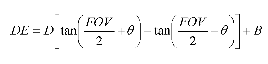
여기서, D는 카메라와 주시각 포인트까지의 거리, FOV(Field of View)는 카메라의 FOV, ![]()
![]()
따라서, [수학식 2]로부터, FOV 및 B가 커짐에 따라 양안차 오차(Disparity error)가 증가하여 시차(Parallax) 왜곡이 증가함을 알 수 있으며, 이는 도 7에 나타낸 바와 같다. Accordingly, it can be seen from Equation 2 that as the FOV and B increase, the disparity error increases and the parallax distortion increases, as shown in FIG. 7.
이러한 시차 왜곡은, 다음의 [수학식 3]과 [수학식 4]를 통하여 계산된 시차왜곡 보정 파라미터(시차 오차)만큼 보간(interpolation)함으로써 보정될 수 있다. 즉, [수학식 3]과 [수학식 4]를 이용하여 시차왜곡 보정 파라미터(시차 오차)를 계산하고, 그 계산된 시차왜곡 보정 파라미터(시차 오차)만큼을 보간함으로써 시차 왜곡을 보정할 수 있게 된다.Such parallax distortion can be corrected by interpolating by the parallax distortion correction parameter (parallax error) calculated through the following Equations 3 and 4 below. That is, by calculating the parallax distortion correction parameter (disparity error) using [Equation 3] and [Equation 4], and by interpolating the calculated parallax distortion correction parameter (disparity error), the parallax distortion can be corrected. do.


여기서, ![]()
![]()
![]()
![]()
![]()
![]()
![]()
![]()
![]()
![]()
![]()
![]()
![]()
![]()
만약, 우측 카메라로부터 획득된 영상(우 영상)의 경우에는, [수학식 3]의 ![]()
![]()
![]()
![]()
상기 ![]()
![]()
![]()
![]()
도 2 는 본 발명에 따른 스테레오 카메라의 영상왜곡 보정 장치의 제 2실시예 구성도이다.2 is a block diagram of a second embodiment of the image distortion correction apparatus of the stereo camera according to the present invention.
도 1에 도시된 바와 같은 스테레오 카메라의 영상왜곡 보정 장치(제 1 실시예)는 제 1 영상과 제 2 영상을 각각 개별적으로 보정하는 방식을 사용한다. 이렇게 개별적으로 보정된 제 1 영상과 제 2 영상은 다중화를 통하여 다양한 3차원 영상이 될 것이다.The image distortion correction apparatus (first embodiment) of the stereo camera as shown in FIG. 1 uses a method of individually correcting the first image and the second image. The individually corrected first and second images will be various three-dimensional images through multiplexing.
한편, 도 2에 도시된 바와 같은 스테레오 카메라의 영상왜곡 보정 장치(제 2 실시예)는 도 2에 도시된 바와 같이, 입력부(200), 입체 영상 보정부(210), 및 출력부(220)를 포함하여 이루어지는 것으로서, 미리 제 1 영상(좌 영상)과 제 2 영상(우 영상)을 다중화하여 하나의 3차원 영상을 생성한 후에 보정을 하는 방식을 사용하는 것이다.On the other hand, the image distortion correction device (second embodiment) of the stereo camera as shown in Figure 2, as shown in Figure 2, the
먼저, 입력부(200)를 상세히 설명하면, 다음과 같다.First, the
입력부(200)는 카메라로부터 획득된 제 1 영상을 입력받는 제 1 영상 입력부(201), 카메라로부터 획득된 제 2 영상을 입력받는 제 2 영상 입력부(202), 외부(예를 들면, 카메라 또는 사용자 등)로부터 카메라의 정보를 입력받는 카메라정보 입력부(203), 및 제 1 영상과 제 2 영상을 Side-by-Side, 또는 Top-Down, Field- by-Field 등의 3차원 영상 포맷에 따라 다중화하여 하나의 3차원 영상을 생성하는 3차원영상 다중화부(204)를 포함하여 이루어진다.The
다음은, 입체 영상 보정부(210)에 대하여 설명하기로 한다.Next, the stereoscopic
입체 영상 보정부(210)는 영상 칼라 보정부(211), 렌즈 왜곡 보정부(212), 시차 왜곡 보정부(213), 및 카메라파라미터 테이블 생성/저장부(214)를 포함한다.The
영상 칼라 보정부(211)는 3차원영상 다중화부(204)에서 다중화된 3차원 영상 내의 제 1 영상과 제 2 영상(좌/우 영상) 간의 칼라 분포가 동일하게 되도록 칼라 보정을 한다. The
그러면, 렌즈 왜곡 보정부(212)는 카메라파라미터 룩업 테이블을 이용하여, 칼라 보정된 3차원 영상의 배럴 왜곡(Barrel Distortion)과 핀쿠션 왜곡(Pincushion Distortion)을 보정한다Then, the lens
이후, 시차 왜곡 보정부(213)는 카메라파라미터 룩업 테이블을 이용하여, 렌즈 왜곡이 보정된 3차원 영상에서 카메라의 FOV에 따른 시차 왜곡을 보정한다.Thereafter, the parallax
한편, 카메라 파라미터 생성/저장부(214)는 카메라정보 입력부(203)로부터 카메라 정보를 입력받아, 이로부터 렌즈 왜곡의 보정에 필요한 파라미터를 생성(산출)하여 룩업(look-up) 테이블로 저장한다. 이에 대해서는 도 9에서 상세히 설명하기로 한다.On the other hand, the camera parameter generation /
마지막으로, 출력부(220)는 입체 영상 보정부(210)에 의해 칼라보정, 렌즈왜곡 보정, 시차왜곡 보정이 이루어진 3차원 보정 영상을 출력하는 기능을 수행한다. Finally, the
요컨대, 도 2에 도시된 바와 같은 제 2 실시예에 따른 영상왜곡 보정 장치에 서의 보정 방법은 기본적으로는 제 1 실시예에 따른 영상왜곡 보정 장치(도 1 참조)에서의 보정 방법과 같다. 즉, 제 2 실시예에서는 3차원 영상 내의 좌/우 영상을 식별하고, 그 식별된 좌/우 영상 각각에 대하여 보정을 하게 되는데, 그 보정 방법은 제 1 실시예에서와 동일하다. 다만, 제 2 실시예에 의하면, 시스템이 간단하고 메모리도 적게 차지하는 장점이 있다.In other words, the correction method in the image distortion correction apparatus according to the second embodiment as shown in Fig. 2 is basically the same as the correction method in the image distortion correction apparatus (see Fig. 1) according to the first embodiment. That is, in the second embodiment, the left and right images in the three-dimensional image are identified, and each of the identified left and right images is corrected. The correction method is the same as in the first embodiment. However, according to the second embodiment, there is an advantage that the system is simple and takes less memory.
도 3a 는 배럴 왜곡(Barrel Distortion)에 대한 설명도이고, 도 3b 는 배럴 왜곡(Barrel Distortion)이 보정된 영상에 대한 설명도이다.3A is an explanatory diagram for barrel distortion, and FIG. 3B is an explanatory diagram for an image in which barrel distortion is corrected.
카메라를 이용하여 근접거리의 객체(Object) 또는 원거리의 객체에 대한 영상을 획득하게 되는데, 이 때 망원렌즈(telephoto lens) 또는 어안렌즈 등을 이용한다. 이와 같은 렌즈를 이용하여 영상을 획득할 경우, 도 3a에 도시된 바와 같은 렌즈에 의한 배럴 왜곡(Barrel Distortion) 또는 핀쿠션 왜곡(Pincushion Distortion)이 발생하게 된다 도 3a와 같이 왜곡된 3차원 영상을 관찰할 경우, 관찰자는 왜곡된 영상을 보게 되고, 이로 인하여 시각피로도 증가하게 된다Using a camera, an image of an object of a close distance or an object of a long distance is obtained, and at this time, a telephoto lens or a fisheye lens is used. When an image is acquired using such a lens, barrel distortion or pincushion distortion is generated by the lens as shown in FIG. 3A. A distorted 3D image is observed as shown in FIG. 3A. In this case, the observer sees the distorted image, which increases visual fatigue.
도 4 는 거리 D에 위치한 면 상에서의 I 간격마다의 광 경로에 대한 설명도이고, 도 5 는 거리 D에 위치한 면에서 스테레오 영상을 획득할 때의 광 경로에 대한 설명도이며, 도 6 은 거리 D에 위치한 면에서 스테레오 영상을 획득할 때 주시각 포인트가 동일한 면에 위치하도록 보정된 광 경로에 대한 설명도이다. 이하, 도 4 내지 도 6을 함께 설명하기로 한다.4 is an explanatory diagram of the optical path for each I interval on the plane located at the distance D, FIG. 5 is an explanatory diagram of the optical path when acquiring stereo images on the plane located at the distance D, and FIG. It is an explanatory diagram of the optical path corrected so that the vergence point is located on the same plane when acquiring stereo images from the plane located at D. Hereinafter, FIGS. 4 to 6 will be described together.
도 4는 렌즈 왜곡이 없는 카메라를 이용하여 거리 D(카메라로부터 떨어진 거리)에 위치한 면에서 영상을 획득했을 때, 거리 D에 위치한 면 상에서의 I 간격마 다의 광 경로를 나타낸 것이다. 이는 렌즈의 수차 및 렌즈 왜곡을 보정한 것과 동일한 것임을 의미한다. FIG. 4 shows an optical path every I interval on the plane located at distance D when an image is acquired at the plane located at distance D (distance from the camera) using a camera without lens distortion. This means that it is the same as correcting lens aberration and lens distortion.
이러한 렌즈 왜곡이 없는 카메라를 이용하여 교차축 방식으로 입체 영상을 획득할 경우, 도 5에 도시된 바와 같이, 주시각 포인트가 거리 D만큼 떨어진 동일한 면에 위치하지 않게 된다. 즉, 3차원 영상을 획득할 때 거리 D에 있는 객체의 영상을 획득할 경우, 주시각 포인트의 거리에서의 양안차(Disparity)는 비선형으로 분포하게 된다. 이를 보정할 경우, 도 6에 도시된 바와 같이 모든 광 경로에서 주시각 포인트가 거리 D에 위치하게 된다. When a stereoscopic image is acquired by using a camera without such lens distortion in a cross-axis manner, as shown in FIG. 5, the vergence points are not positioned on the same plane separated by a distance D. That is, when acquiring an image of an object at a distance D when acquiring a 3D image, the disparity in the distance of the vergence point is distributed non-linearly. When correcting this, as shown in FIG. 6, the vergence point is located at the distance D in all the optical paths.
도 7 은 시야각(FOV)에 따른 양안차 오차(Disparity Error)의 분포도로서, 카메라의 렌즈 초점 거리에 따라 시야각(FOV)이 달라짐을 나타내고, 또한 FOV가 커짐에 따라 양안차 오차(Disparity error)가 증가하여 시차(Parallax) 왜곡이 증가함을 나타낸다. FIG. 7 is a distribution diagram of the disparity error according to the field of view (FOV), and shows that the field of view (FOV) varies according to the lens focal length of the camera, and as the FOV increases, the disparity error is increased. Increasing, indicating an increase in parallax distortion.
도 8 은 시차 왜곡 분포에 대한 설명도로서, ![]()
![]()
![]()
![]()
도 9 는 본 발명에 따른 카메라 파라미터 생성/저장부의 일실시예 구성도이다.9 is a diagram illustrating an embodiment of a camera parameter generation / storage unit according to the present invention.
카메라 파라미터 생성/저장부(900)는 도 9에 도시된 바와 같이, 카메라 파라미터 생성부(901)와 카메라 파라미터 저장부(902)를 포함한다.As illustrated in FIG. 9, the camera parameter generation /
카메라 파라미터 생성부(901)는 카메라정보 입력부(103)가 외부로부터 입력받은 카메라 정보를 전달받고, 그 전달받은 카메라 정보와 사전에 입력된 CCD(Charge Coupled Device) 센서의 직경정보를 이용하여 카메라 파라미터를 생성한다. 그리고, 카메라 정보 등이 갱신된 경우에는 그에 따라 카메라 파라미터도 다시 생성한다. 여기서, 카메라 정보에는 카메라 렌즈의 초점거리(f: Lens focal length), 카메라의 회전각(θ: Camera rotation angle), 카메라와 주 객체간의 거리(Dv: Object Distance), 및 카메라 간의 거리(B: Base Line) 등이 포함된다. The
보다 상세하게, 카메라 파라미터 생성부(901)는 초점 거리에 따른 렌즈의 왜곡 파라미터(k)를 미리 연산을 통해 생성하여 저장해 둔다. 즉, 카메라 파라미터 생성부(901)는 카메라의 CCD 직경 정보 및 초점 거리(f)를 이용하여 FOV를 산출하고, 그 산출된 FOV를 이용하여 렌즈왜곡 파라미터(k)를 산출하여 카메라 파라미터 저장부(902)에 저장한다.In more detail, the
한편, 카메라 파라미터 생성부(901)는 카메라와 주 객체간의 거리(Dv)와 카메라 간의 거리(B)를 이용하여 시차왜곡이 보정되어야 할 위치인 DC 를 산출한다. 그리고, 카메라와 주 객체간의 거리(Dv), 카메라 간의 거리(B), 및 산출된 DC 를 이용하여 시차왜곡 보정 파라미터인 ![]()
![]()
![]()
![]()
한편, 카메라 파라미터 저장부(902)는 카메라 파라미터 생성부(901)에서 생성(산출)된 카메라 파라미터들을 룩업테이블(Look-Up Table)로 구성하여 저장한다. 따라서 카메라 렌즈에 의한 렌즈 왜곡 보정 및 시차 왜곡 보정을 할 때 이 룩업 (Look-up) 테이블만을 참조하여 고속으로 보정을 할 수 있게 된다. On the other hand, the camera
상술한 바와 같은 본 발명의 방법은 프로그램으로 구현되어 컴퓨터로 읽을 수 있는 형태로 기록매체(씨디롬, 램, 롬, 플로피 디스크, 하드 디스크, 광자기 디스크 등)에 저장될 수 있다. 이러한 과정은 본 발명이 속하는 기술 분야에서 통상의 지식을 가진 자가 용이하게 실시할 수 있으므로 더 이상 상세히 설명하지 않기로 한다.As described above, the method of the present invention may be implemented as a program and stored in a recording medium (CD-ROM, RAM, ROM, floppy disk, hard disk, magneto-optical disk, etc.) in a computer-readable form. Since this process can be easily implemented by those skilled in the art will not be described in more detail.
이상에서 설명한 본 발명은, 본 발명이 속하는 기술분야에서 통상의 지식을 가진 자에게 있어 본 발명의 기술적 사상을 벗어나지 않는 범위 내에서 여러 가지 치환, 변형 및 변경이 가능하므로 전술한 실시예 및 첨부된 도면에 의해 한정되는 것이 아니다.The present invention described above is capable of various substitutions, modifications, and changes without departing from the technical spirit of the present invention for those skilled in the art to which the present invention pertains. It is not limited by the drawings.
상기와 같은 본 발명은, 3차원 영상의 시차왜곡을 보정함으로써, 즉 일정거리에 있는 촬영 객체들의 양안차(Disparity) 분포를 균일하게 함으로써, 3차원 영상 관찰자로 하여금 시각 피로없이 편안하게 3차원 영상을 관찰할 수 있게 하는 효과가 있다. The present invention as described above, by correcting the parallax distortion of the three-dimensional image, that is, by uniformizing the distribution of binocular disparity (disparity) of the photographing objects at a certain distance, allows the three-dimensional image observer comfortable three-dimensional image It is effective to observe.
또한, 본 발명에 따라 왜곡이 보정된 3차원 영상을 3차원 영상 디스플레이 등에 활용할 경우, 왜곡에 의해 중앙의 돌출감 및 칼라 비일치로 인한 어색함, 렌즈 왜곡에 의한 부자연스러운 3차원 입체 효과 등의 제거로 인한, 자연스럽고 시각 피로도 낮은 3차원 입체 영상을 제공하는 효과가 있다.In addition, when using a three-dimensional image with distortion correction according to the present invention, such as a three-dimensional image display, the removal of awkwardness due to the center of the protrusion and color mismatch by the distortion, unnatural three-dimensional stereoscopic effect due to lens distortion, etc. Due to this, there is an effect of providing a three-dimensional stereoscopic image that is natural and low visual fatigue.
Claims (17)


Priority Applications (2)
| Application Number | Priority Date | Filing Date | Title |
|---|---|---|---|
| JP2007545366A JP4995092B2 (en) | 2004-12-06 | 2005-12-06 | Stereo camera image distortion correction apparatus and method |
| PCT/KR2005/004140 WO2006062325A1 (en) | 2004-12-06 | 2005-12-06 | Apparatus for correcting image distortion of stereo-camera and method thereof |
Applications Claiming Priority (2)
| Application Number | Priority Date | Filing Date | Title |
|---|---|---|---|
| KR20040101775 | 2004-12-06 | ||
| KR1020040101775 | 2004-12-06 |
Publications (2)
| Publication Number | Publication Date |
|---|---|
| KR20060063575A KR20060063575A (en) | 2006-06-12 |
| KR100770019B1 true KR100770019B1 (en) | 2007-10-25 |
Family
ID=37159549
Family Applications (1)
| Application Number | Title | Priority Date | Filing Date |
|---|---|---|---|
| KR1020050038568A Expired - Fee Related KR100770019B1 (en) | 2004-12-06 | 2005-05-09 | Apparatus and Method for correction of the image distortion of stereo-camera |
Country Status (2)
| Country | Link |
|---|---|
| JP (1) | JP4995092B2 (en) |
| KR (1) | KR100770019B1 (en) |
Cited By (3)
| Publication number | Priority date | Publication date | Assignee | Title |
|---|---|---|---|---|
| US10375337B2 (en) | 2015-09-25 | 2019-08-06 | Samsung Electronics Co., Ltd. | Method controlling image sensor parameters |
| KR20210080646A (en) * | 2019-12-20 | 2021-07-01 | (주)제이에스씨스템 | Tracking path replay device and method for coaching billiard thereof |
| KR102360522B1 (en) | 2021-03-04 | 2022-02-08 | 한남대학교 산학협력단 | 3D spatial information acquisition system using parallax phenomenon |
Families Citing this family (15)
| Publication number | Priority date | Publication date | Assignee | Title |
|---|---|---|---|---|
| KR101311896B1 (en) * | 2006-11-14 | 2013-10-14 | 삼성전자주식회사 | Displacement adjustment method of stereoscopic image and stereoscopic image device applying the same |
| JP5348687B2 (en) * | 2009-04-17 | 2013-11-20 | Necカシオモバイルコミュニケーションズ株式会社 | Terminal device and program |
| JP5297899B2 (en) * | 2009-06-01 | 2013-09-25 | 株式会社エヌエイチケイメディアテクノロジー | Stereoscopic image adjustment device, stereoscopic image adjustment system, and program |
| CN102113013A (en) | 2009-07-22 | 2011-06-29 | 松下电器产业株式会社 | Parallax detection apparatus, ranging apparatus and parallax detection method |
| JP2011049733A (en) * | 2009-08-26 | 2011-03-10 | Clarion Co Ltd | Camera calibration device and video distortion correction device |
| JP5481337B2 (en) * | 2010-09-24 | 2014-04-23 | 株式会社東芝 | Image processing device |
| JP5742179B2 (en) * | 2010-11-05 | 2015-07-01 | ソニー株式会社 | Imaging apparatus, image processing apparatus, image processing method, and program |
| WO2012066768A1 (en) * | 2010-11-19 | 2012-05-24 | パナソニック株式会社 | Stereo image generation device and stereo image generation method |
| CN103430094B (en) * | 2011-03-30 | 2017-03-01 | 株式会社尼康 | Image processing device, photographing device, and image processing program |
| KR101276208B1 (en) | 2011-05-30 | 2013-06-18 | 전자부품연구원 | Calibration system for stereo camera and calibration apparatus for calibrating strero image |
| KR101316196B1 (en) | 2011-12-23 | 2013-10-08 | 연세대학교 산학협력단 | Apparatus and method for enhancing stereoscopic image, recording medium thereof |
| EP2804369A4 (en) * | 2012-01-10 | 2016-03-09 | Konica Minolta Inc | Image processing method, image processing apparatus, and image processing program |
| KR101373471B1 (en) * | 2012-10-15 | 2014-03-13 | 세종대학교산학협력단 | Apparatus and method for compensation of stereo image |
| KR101558805B1 (en) | 2014-09-03 | 2015-10-07 | 현대자동차주식회사 | Interpolation factors correction apparatus for stereo matching |
| KR102620873B1 (en) * | 2020-11-27 | 2024-01-05 | 한국과학기술원 | Image stitching method and apparatus for performing the same |
Citations (2)
| Publication number | Priority date | Publication date | Assignee | Title |
|---|---|---|---|---|
| KR960028194A (en) * | 1994-12-23 | 1996-07-22 | 양승택 | Image Distortion Correction Method of Camera Using Neural Network |
| KR20040063656A (en) * | 2003-01-08 | 2004-07-14 | 엘지전자 주식회사 | Digital convergence device based on 3-d virtual screen of video display system |
Family Cites Families (11)
| Publication number | Priority date | Publication date | Assignee | Title |
|---|---|---|---|---|
| JPH0843055A (en) * | 1994-07-29 | 1996-02-16 | Canon Inc | Three-dimensional object shape recognition method and device |
| JPH08126034A (en) * | 1994-10-20 | 1996-05-17 | Canon Inc | Stereoscopic image display device and method |
| JP3147002B2 (en) * | 1996-09-26 | 2001-03-19 | 富士電機株式会社 | Correction method of distance detection value |
| JP3284190B2 (en) * | 1998-05-14 | 2002-05-20 | 富士重工業株式会社 | Image correction device for stereo camera |
| JPH11341522A (en) * | 1998-05-22 | 1999-12-10 | Fuji Photo Film Co Ltd | Stereoscopic image photographing device |
| JP3263931B2 (en) * | 1999-09-22 | 2002-03-11 | 富士重工業株式会社 | Stereo matching device |
| JP3261115B2 (en) * | 1999-09-22 | 2002-02-25 | 富士重工業株式会社 | Stereo image processing device |
| JP2002250857A (en) * | 2001-02-26 | 2002-09-06 | Olympus Optical Co Ltd | Range finder |
| JP2003329439A (en) * | 2002-05-15 | 2003-11-19 | Honda Motor Co Ltd | Distance detection device |
| JP4397573B2 (en) * | 2002-10-02 | 2010-01-13 | 本田技研工業株式会社 | Image processing device |
| JP3728460B2 (en) * | 2003-05-15 | 2005-12-21 | 独立行政法人 宇宙航空研究開発機構 | Method and system for determining optimal arrangement of stereo camera |
-
2005
- 2005-05-09 KR KR1020050038568A patent/KR100770019B1/en not_active Expired - Fee Related
- 2005-12-06 JP JP2007545366A patent/JP4995092B2/en not_active Expired - Fee Related
Patent Citations (2)
| Publication number | Priority date | Publication date | Assignee | Title |
|---|---|---|---|---|
| KR960028194A (en) * | 1994-12-23 | 1996-07-22 | 양승택 | Image Distortion Correction Method of Camera Using Neural Network |
| KR20040063656A (en) * | 2003-01-08 | 2004-07-14 | 엘지전자 주식회사 | Digital convergence device based on 3-d virtual screen of video display system |
Cited By (7)
| Publication number | Priority date | Publication date | Assignee | Title |
|---|---|---|---|---|
| US10375337B2 (en) | 2015-09-25 | 2019-08-06 | Samsung Electronics Co., Ltd. | Method controlling image sensor parameters |
| US10868993B2 (en) | 2015-09-25 | 2020-12-15 | Samsung Electronics Co., Ltd. | Method controlling image sensor parameters |
| US11184570B2 (en) | 2015-09-25 | 2021-11-23 | Samsung Electronics Co., Ltd. | Method controlling image sensor parameters |
| US11699218B2 (en) | 2015-09-25 | 2023-07-11 | Samsung Electronics Co., Ltd. | Method controlling image sensor parameters |
| KR20210080646A (en) * | 2019-12-20 | 2021-07-01 | (주)제이에스씨스템 | Tracking path replay device and method for coaching billiard thereof |
| KR102294082B1 (en) | 2019-12-20 | 2021-08-27 | (주)제이에스씨스템 | Tracking path replay device and method for coaching billiard thereof |
| KR102360522B1 (en) | 2021-03-04 | 2022-02-08 | 한남대학교 산학협력단 | 3D spatial information acquisition system using parallax phenomenon |
Also Published As
| Publication number | Publication date |
|---|---|
| JP2008524673A (en) | 2008-07-10 |
| JP4995092B2 (en) | 2012-08-08 |
| KR20060063575A (en) | 2006-06-12 |
Similar Documents
| Publication | Publication Date | Title |
|---|---|---|
| KR100770019B1 (en) | Apparatus and Method for correction of the image distortion of stereo-camera | |
| US7557824B2 (en) | Method and apparatus for generating a stereoscopic image | |
| EP2357841B1 (en) | Method and apparatus for processing three-dimensional images | |
| US8116557B2 (en) | 3D image processing apparatus and method | |
| EP2532166B1 (en) | Method, apparatus and computer program for selecting a stereoscopic imaging viewpoint pair | |
| KR100456952B1 (en) | Stereoscopic cg moving image generating apparatus | |
| US20150358539A1 (en) | Mobile Virtual Reality Camera, Method, And System | |
| EP1089573A2 (en) | Method of producing a stereoscopic image | |
| KR20110124473A (en) | 3D image generating device and method for multi-view image | |
| US9443338B2 (en) | Techniques for producing baseline stereo parameters for stereoscopic computer animation | |
| WO2006062325A1 (en) | Apparatus for correcting image distortion of stereo-camera and method thereof | |
| US20110157319A1 (en) | Method and apparatus for processing three-dimensional images | |
| US9571824B2 (en) | Stereoscopic image display device and displaying method thereof | |
| JP6585938B2 (en) | Stereoscopic image depth conversion apparatus and program thereof | |
| KR20120030005A (en) | Image processing device and method, and stereoscopic image display device | |
| KR100439341B1 (en) | Depth of field adjustment apparatus and method of stereo image for reduction of visual fatigue | |
| JP6113411B2 (en) | Image processing device | |
| KR100952045B1 (en) | Apparatus and method for displaying three-dimensional image without distortion | |
| JP3054312B2 (en) | Image processing apparatus and method | |
| JP2022550168A (en) | Method and apparatus for processing image content | |
| JP2012134885A (en) | Image processing system and image processing method | |
| CN116704114A (en) | A Depth Map Synthesis Method for High-Resolution Wide Field of View Virtual Viewpoint Generation | |
| JP2012227798A (en) | Stereoscopic image generation method and stereoscopic image generation system | |
| KR20040018858A (en) | Depth of field adjustment apparatus and method of stereo image for reduction of visual fatigue | |
| WO2012063540A1 (en) | Virtual viewpoint image generating device |
Legal Events
| Date | Code | Title | Description |
|---|---|---|---|
| A201 | Request for examination | ||
| PA0109 | Patent application |
St.27 status event code: A-0-1-A10-A12-nap-PA0109 |
|
| PA0201 | Request for examination |
St.27 status event code: A-1-2-D10-D11-exm-PA0201 |
|
| PG1501 | Laying open of application |
St.27 status event code: A-1-1-Q10-Q12-nap-PG1501 |
|
| E902 | Notification of reason for refusal | ||
| PE0902 | Notice of grounds for rejection |
St.27 status event code: A-1-2-D10-D21-exm-PE0902 |
|
| P11-X000 | Amendment of application requested |
St.27 status event code: A-2-2-P10-P11-nap-X000 |
|
| P13-X000 | Application amended |
St.27 status event code: A-2-2-P10-P13-nap-X000 |
|
| E701 | Decision to grant or registration of patent right | ||
| PE0701 | Decision of registration |
St.27 status event code: A-1-2-D10-D22-exm-PE0701 |
|
| GRNT | Written decision to grant | ||
| PR0701 | Registration of establishment |
St.27 status event code: A-2-4-F10-F11-exm-PR0701 |
|
| PR1002 | Payment of registration fee |
St.27 status event code: A-2-2-U10-U11-oth-PR1002 Fee payment year number: 1 |
|
| PG1601 | Publication of registration |
St.27 status event code: A-4-4-Q10-Q13-nap-PG1601 |
|
| PN2301 | Change of applicant |
St.27 status event code: A-5-5-R10-R13-asn-PN2301 St.27 status event code: A-5-5-R10-R11-asn-PN2301 |
|
| PR1001 | Payment of annual fee |
St.27 status event code: A-4-4-U10-U11-oth-PR1001 Fee payment year number: 4 |
|
| PR1001 | Payment of annual fee |
St.27 status event code: A-4-4-U10-U11-oth-PR1001 Fee payment year number: 5 |
|
| FPAY | Annual fee payment |
Payment date: 20121011 Year of fee payment: 6 |
|
| PR1001 | Payment of annual fee |
St.27 status event code: A-4-4-U10-U11-oth-PR1001 Fee payment year number: 6 |
|
| L13-X000 | Limitation or reissue of ip right requested |
St.27 status event code: A-2-3-L10-L13-lim-X000 |
|
| U15-X000 | Partial renewal or maintenance fee paid modifying the ip right scope |
St.27 status event code: A-4-4-U10-U15-oth-X000 |
|
| FPAY | Annual fee payment |
Payment date: 20130923 Year of fee payment: 7 |
|
| PR1001 | Payment of annual fee |
St.27 status event code: A-4-4-U10-U11-oth-PR1001 Fee payment year number: 7 |
|
| LAPS | Lapse due to unpaid annual fee | ||
| PC1903 | Unpaid annual fee |
St.27 status event code: A-4-4-U10-U13-oth-PC1903 Not in force date: 20141019 Payment event data comment text: Termination Category : DEFAULT_OF_REGISTRATION_FEE |
|
| PN2301 | Change of applicant |
St.27 status event code: A-5-5-R10-R13-asn-PN2301 St.27 status event code: A-5-5-R10-R11-asn-PN2301 |
|
| PC1903 | Unpaid annual fee |
St.27 status event code: N-4-6-H10-H13-oth-PC1903 Ip right cessation event data comment text: Termination Category : DEFAULT_OF_REGISTRATION_FEE Not in force date: 20141019 |
|
| P22-X000 | Classification modified |
St.27 status event code: A-4-4-P10-P22-nap-X000 |
|
| P22-X000 | Classification modified |
St.27 status event code: A-4-4-P10-P22-nap-X000 |
|
| P22-X000 | Classification modified |
St.27 status event code: A-4-4-P10-P22-nap-X000 |