KR100714690B1 - Method and apparatus for detecting topology of nodes and bridges in network - Google Patents
Method and apparatus for detecting topology of nodes and bridges in network Download PDFInfo
- Publication number
- KR100714690B1 KR100714690B1 KR1020050029096A KR20050029096A KR100714690B1 KR 100714690 B1 KR100714690 B1 KR 100714690B1 KR 1020050029096 A KR1020050029096 A KR 1020050029096A KR 20050029096 A KR20050029096 A KR 20050029096A KR 100714690 B1 KR100714690 B1 KR 100714690B1
- Authority
- KR
- South Korea
- Prior art keywords
- node
- nodes
- information
- network
- message
- Prior art date
- Legal status (The legal status is an assumption and is not a legal conclusion. Google has not performed a legal analysis and makes no representation as to the accuracy of the status listed.)
- Expired - Fee Related
Links
Images


Classifications
-
- H—ELECTRICITY
- H04—ELECTRIC COMMUNICATION TECHNIQUE
- H04L—TRANSMISSION OF DIGITAL INFORMATION, e.g. TELEGRAPHIC COMMUNICATION
- H04L41/00—Arrangements for maintenance, administration or management of data switching networks, e.g. of packet switching networks
- H04L41/12—Discovery or management of network topologies
-
- H—ELECTRICITY
- H04—ELECTRIC COMMUNICATION TECHNIQUE
- H04L—TRANSMISSION OF DIGITAL INFORMATION, e.g. TELEGRAPHIC COMMUNICATION
- H04L12/00—Data switching networks
- H04L12/28—Data switching networks characterised by path configuration, e.g. LAN [Local Area Networks] or WAN [Wide Area Networks]
- H04L12/46—Interconnection of networks
- H04L12/4604—LAN interconnection over a backbone network, e.g. Internet, Frame Relay
- H04L12/462—LAN interconnection over a bridge based backbone
-
- H—ELECTRICITY
- H04—ELECTRIC COMMUNICATION TECHNIQUE
- H04L—TRANSMISSION OF DIGITAL INFORMATION, e.g. TELEGRAPHIC COMMUNICATION
- H04L12/00—Data switching networks
- H04L12/28—Data switching networks characterised by path configuration, e.g. LAN [Local Area Networks] or WAN [Wide Area Networks]
- H04L12/2803—Home automation networks
- H04L12/283—Processing of data at an internetworking point of a home automation network
- H04L12/2832—Interconnection of the control functionalities between home networks
-
- H—ELECTRICITY
- H04—ELECTRIC COMMUNICATION TECHNIQUE
- H04L—TRANSMISSION OF DIGITAL INFORMATION, e.g. TELEGRAPHIC COMMUNICATION
- H04L12/00—Data switching networks
- H04L12/28—Data switching networks characterised by path configuration, e.g. LAN [Local Area Networks] or WAN [Wide Area Networks]
- H04L12/2803—Home automation networks
- H04L2012/2847—Home automation networks characterised by the type of home appliance used
- H04L2012/285—Generic home appliances, e.g. refrigerators
Landscapes
- Engineering & Computer Science (AREA)
- Computer Networks & Wireless Communication (AREA)
- Signal Processing (AREA)
- Automation & Control Theory (AREA)
- Computing Systems (AREA)
- Small-Scale Networks (AREA)
- Data Exchanges In Wide-Area Networks (AREA)
Abstract
네트워크를 구성하는 노드들과 브리지의 위상을 검출하는 방법 및 장치에 관한 것이다.A method and apparatus for detecting a topology of nodes and a bridge constituting a network.
본 발명의 일 실시예에 따른 네트워크를 구성하는 노드들과 브리지의 위상을 검출하는 방법은 네트워크를 구성하는 노드들에게 모드 변경을 요청하는 메시지를 송신하는 단계, 상기 노드들에게 체크 메시지를 송신하는 단계, 상기 노드들이 상기 체크 메시지를 수신한 결과인 수신노드 정보를 상기 노드들로부터 수신하는 단계, 상기 수신노드 정보에서 같은 회선에 결합한 노드들의 결합 정보를 계산하는 단계, 및 상기 결합 정보와 상기 수신노드 정보를 통해 브리지와 노드들의 위상 정보를 추출하는 단계를 포함한다.According to an embodiment of the present invention, a method for detecting a topology of nodes and a bridge constituting a network may include transmitting a message requesting a mode change to nodes constituting the network, and transmitting a check message to the nodes. Receiving, from the nodes, receiving node information that is the result of receiving the check message from the nodes, calculating combining information of nodes coupled to the same line in the receiving node information, and receiving the combining information and the receiving information. Extracting topology information of the bridge and the nodes through the node information.
전패킷 수신 모드(Promiscuous mode), 브리지(Bridge), 위상(Topology), 네트워크 Promiscuous mode, Bridge, Topology, Network
Description
도 1은 브리지의 동작을 간략히 보여주는 예시도이다.1 is an exemplary view briefly showing the operation of the bridge.
도 2는 종래의 네트워크에서 스패닝 트리 프로토콜이 동작하는 과정을 보여주는 예시도이다.2 is an exemplary view illustrating a process of operating a spanning tree protocol in a conventional network.
도 3은 본 발명의 일 실시예에 따른 네트워크의 위상과 브리지의 연결 상태를 검출하기 위해 송수신되는 메시지의 흐름을 보여주는 예시도이다.3 is an exemplary diagram showing a flow of messages transmitted and received to detect a topology of a network and a connection state of a bridge according to an embodiment of the present invention.
도 4는 본 발명의 일 실시예에 따른 네트워크의 위상과 브리지의 연결 상태를 검출하기 위해 상기 도 3 이후에 송수신되는 메시지와 동작을 보여주는 예시도이다. 4 is an exemplary diagram illustrating a message and an operation transmitted and received after FIG. 3 to detect a topology of a network and a connection state of a bridge according to an embodiment of the present invention.
도 5는 본 발명의 일 실시예에 따른 브리지를 검출하는 알고리즘이다. 5 is an algorithm for detecting a bridge according to an embodiment of the present invention.
도 6은 본 발명의 일 실시예에 따른 브리지의 위상을 계산하는 알고리즘이다.6 is an algorithm for calculating the phase of a bridge according to an embodiment of the present invention.
도 7은 본 발명의 일 실시예에 따른 마스터에서의 작업의 순서를 보여주는 순서도이다.7 is a flow chart showing the sequence of operations in the master according to an embodiment of the present invention.
도 8은 본 발명의 일 실시예에 따른 네트워크 위상 정보를 추출하는 네트워 크 장치의 구성도이다.8 is a configuration diagram of a network device for extracting network topology information according to an embodiment of the present invention.
<도면의 주요 부분에 대한 부호의 설명><Explanation of symbols for the main parts of the drawings>
100 : 브리지 200 : 노드100: bridge 200: node
501, 502, 503 : 회선501, 502, 503 line
본 발명은 네트워크를 구성하는 노드들과 브리지의 위상을 검출하는 방법 및 장치에 관한 것이다.The present invention relates to a method and apparatus for detecting a phase of a node and a bridge constituting a network.
통신 네트워크에서, 브리지(Bridge)는 하나의 랜을 이더넷이나 토큰링과 같이 서로 같은 프로토콜을 쓰고 있는 다른 랜과 연결시켜주는 제품을 말하며, 각 랜에 연결되어 있는 스테이션들은 프로토콜을 바꾸지 않고서도 랜이 확장되는 혜택을 받을 수 있게 된다. 브리지는 랜 상의 각 메시지들을 조사한 다음, 같은 랜으로 보내야할 메시지는 받아들이고, 연결되어 있는 다른 랜으로 보내야 할 것들은 넘겨주는 식으로 동작한다. In a communication network, a bridge is a product that connects one LAN with another LAN using the same protocol as Ethernet or Token Ring. Stations connected to each LAN are connected to each other without changing protocols. You will be able to receive extended benefits. The bridge works by examining each message on the LAN, accepting messages that need to be sent to the same LAN, and passing those that need to be sent to other connected LANs.
브리지로 연결된 네트워크들에서 컴퓨터나 노드의 주소들은 실제 위치와 특별한 상관관계가 없다. 이러한 이유로, 모든 메시지들은 네트워크 상의 모든 주소로 보내지지만, 그 메시지들은 오직 목적지 노드에 의해서만 받아들여진다. 브리지는 어떤 주소들이 어떤 네트워크에 있는지를 미리 파악하고, 메시지들을 정확히 다른 네트워크로 전달할 수 있도록 미리 표를 작성해 놓는다. 이러한 표를 필터링 데 이터베이스(Filtering Database)라고 한다.In bridged networks, the address of a computer or node has no special correlation with its actual location. For this reason, all messages are sent to all addresses on the network, but the messages are only accepted by the destination node. The bridge knows in advance which addresses are on which networks, and pre-populates the tables so that messages can be forwarded to exactly the other network. Such a table is called a filtering database.
브리지로 연결된 네트워크들은 일반적으로 항상 랜에 상호 연결되어 있고, 모든 메시지들을 브로드캐스팅하기 때문에 대형 네트워크인 경우 불필요한 네트워크 트래픽들이 쇄도할 수도 있다. 이러한 이유로, 인터넷과 같은 라우팅 네트워크는 각 노드에 주소를 할당함으로써, 메시지나 패킷들이 모든 방향으로 전달되는 대신에 한 방향으로만 전달될 수 있도록 하고 있다. Bridged networks are usually always interconnected to the LAN and broadcast all messages, which can flood unnecessary network traffic in large networks. For this reason, routing networks such as the Internet assign addresses to each node so that messages or packets can be delivered in only one direction instead of in all directions.
브리지는 네트워크의 데이터링크 계층에서, 통신 선로를 따라 한 네트워크에서 그 다음 네트워크로 데이터 프레임을 복사하는 일을 한다. The bridge is responsible for copying data frames from one network to the next along the communication line at the datalink layer of the network.
브리지에 연결되어 통신을 수행하는 각 개체들을 노드(Node)라 한다. 네트워크를 구성시 다수의 브리지가 노드들 사이에 존재할 수 있다. 따라서 네트워크를 관리하기 위해서 브리지의 위상을 관리하고 어떤 브리지에 어떤 노드가 연결되어 있는지에 대한 정보를 얻는 것이 필요하다. Each entity connected to the bridge and performing communication is called a node. In constructing a network, multiple bridges may exist between nodes. Therefore, in order to manage the network, it is necessary to manage the topology of the bridge and obtain information about which node is connected to which bridge.
도 1은 브리지의 동작을 간략히 보여주는 예시도이다. 도 1에서 브리지(100)를 중심으로 노드 1(201), 노드 2(202)가 동일한 회선에 연결되어 있으며, 노드 3(203)는 다른 회선에 연결되어 있다. 한편 브리지(100)는 자신의 양 포트(포트 1, 포트 2)에 연결된 노드가 어떤 노드인지를 테이블 또는 데이터베이스화하여 필터링 데이터베이스(Filtering Database)에 저장한다. 1 is an exemplary view briefly showing the operation of the bridge. In FIG. 1,
포트 1에는 노드 1, 노드 2가 연결되어 있다는 정보와 노드 1, 노드 2의 MAC 주소가 191에 저장되어 있다. 포트 2에는 노드 3이 연결되어 있다는 정보와 노드 3의 MAC 주소가 192에 저장되어 있다. 브리지(100)는 포트 1을 통해 들어온 데이터 가 포트 2에 연결된 데이터인지를 판단하여, 포트 2로 연결된 노드로 보내는 것이라면 포트 1을 통해 들어온 데이터를 포트 2로 보낸다. 그러나 포트 2에 연결된 노드가 아니라면 데이터는 버린다. 만약 포트가 다수가 존재하며, 특정 포트를 통해 들어온 데이터가, 상기 특정 포트 이외의 다른 포트에 보내질 데이터가 아니라면, 브리지가 데이터를 버리는(discard) 메커니즘을 취한다.
만약 노드 1(201)이 노드 2(202)로 데이터를 송신한다면, 브리지(100)는 포트 1을 통해 들어온 데이터를 포트 2로 넘기지 않는다. 노드 1(201)과 노드 2(202)는 동일 회선에 연결되어 있으므로 노드 2(202)는 데이터를 받을 수 있다. 한편, 노드 1(201)이 노드 3(203)으로 데이터를 송신한다면, 브리지(100)는 포트 2에 노드 3이 연결되어 있다는 정보를 192에 저장하고 있으므로, 수신한 데이터를 포트 2를 통해 송신한다.If
과거 브리지가 연결된 위상을 검출하기 위해 스패닝 트리 프로토콜(Spanning Tree Protocol)을 사용하였다. 위상을 검출하는 것은 브리지로 구성된 네트워크에서 루프(Loop)가 발생하는 것을 막아서, 메시지가 루프를 통해 과도하게 많이 전달되는 현상을 막기 위함이다. 스패닝 트리 프로토콜에 대한 상세한 정보는 802.1d에 명시되어 있다. 스패닝 트리의 동작은 도 2와 같다. In the past, the Spanning Tree Protocol was used to detect the topology of bridges. Detecting the phase is to prevent the loop from occurring in the bridge network, and to prevent the excessive propagation of the message through the loop. Detailed information about the Spanning Tree Protocol is specified in 802.1d. The operation of the spanning tree is shown in FIG.
도 2는 종래의 네트워크에서 스패닝 트리 프로토콜이 동작하는 과정을 보여주는 예시도이다. 먼저 루트 브리지(Root Bridge)(101)를 선택한다. 이때 루트 브리지를 선택하기 위해서는 다양한 기준을 적용할 수 있다. 예를 들어 가장 우선순위가 낮은 브리지를 선택하고, 둘 이상의 경우 MAC 주소가 가장 낮은 브리지를 루 트로 선택한다. 그리고 각 브리지에서 루트로 가기위한 최적의 경로를 선택한 후에 루트 포트를 선정한다. 2 is an exemplary view illustrating a process of operating a spanning tree protocol in a conventional network. First, the
루트 포트(Root Port)는 루트 브리지와 연결된 포트를 의미한다. 이후 루트 브리지까지의 경로상에 있는 브리지의 비용을 모두 합하여 루트 코스트(Root Cost)를 계산한다. 그리고 각 브로드캐스트 세그먼트(Broadcast Segment)에서 루트 브리지까지의 통신을 책임질 지정 브리지(Designated Bridge)(104)를 선정한다. 마지막으로 루트 포트와 지정 포트(Designated Port)를 제외한 막힌 포트(Blocking Port)를 결정한다. 막힌 포트는 다른 포트를 통해 데이터가 전송되므로 데이터를 보낼 필요가 없는 포트를 의미한다. 지정 브리지(104)가 존재하므로, 102 브리지는 데이터를 보낼 필요가 없으므로 막힌 포트를 가지게 된다.Root Port means the port connected to the Root Bridge. The root cost is then calculated by summing all the costs of the bridges on the path to the root bridge. A designated
이러한 과정을 통해 불필요한 메시지가 중복되어 전송되는 루프를 막고 최적의 경로를 통해 메시지를 보낼 수 있다. This prevents loops in which unnecessary messages are duplicated and sends messages through the optimal path.
그런데, 이러한 프로토콜은 브리지의 위상을 검출하여 루프를 방지하기 위한 것이며, 네트워크를 구성하는 노드들의 위상을 검출하기 위한 것이 아니다. 또한 라우터(Router)에서 사용되는 프로토콜은 라우팅만을 위해 사용되고 실제 서브네트워크 내에 존재하는 브리지는 검출할 수 없었다. 특히, 홈 네트워크와 같은 소규모 네트워크를 구성하는 브리지는 복잡한 프로토콜을 지원하지 않는 경우가 많으므로, 간단하게 브리지와 노드의 위상을 검출하여 관리할 수 있는 방안이 필요하다.However, such a protocol is to prevent loops by detecting a phase of a bridge and not to detect a phase of nodes constituting a network. In addition, the protocol used in the router is used only for routing and could not detect a bridge existing in the actual subnetwork. In particular, bridges constituting small networks, such as home networks, often do not support complex protocols. Therefore, there is a need for a method of simply detecting and managing the topology of bridges and nodes.
본 발명의 기술적 과제는 네트워크를 구성하는 브리지와 노드의 위상 정보를 검출하는 데 있다.An object of the present invention is to detect the phase information of the bridge and the node constituting the network.
본 발명의 다른 기술적 과제는 홈 네트워크와 같은 소규모 네트워크에 존재하는 브리지에 복잡한 프로토콜을 부가하지 않고 네트워크를 관리하는데 있다.Another technical problem of the present invention is to manage a network without adding a complicated protocol to a bridge existing in a small network such as a home network.
본 발명의 목적들은 이상에서 언급한 목적들로 제한되지 않으며, 언급되지 않은 또 다른 목적들은 아래의 기재로부터 당업자에게 명확하게 이해될 수 있을 것이다.The objects of the present invention are not limited to the above-mentioned objects, and other objects that are not mentioned will be clearly understood by those skilled in the art from the following description.
네트워크를 구성하는 노드들과 브리지의 위상을 검출하는 방법 및 장치에 관한 것이다.A method and apparatus for detecting a topology of nodes and a bridge constituting a network.
본 발명의 일 실시예에 따른 네트워크를 구성하는 노드들과 브리지의 위상을 검출하는 방법은 네트워크를 구성하는 노드들에게 모드 변경을 요청하는 메시지를 송신하는 단계, 상기 노드들에게 체크 메시지를 송신하는 단계, 상기 노드들이 상기 체크 메시지를 수신한 결과인 수신노드 정보를 상기 노드들로부터 수신하는 단계, 상기 수신노드 정보에서 같은 회선에 결합한 노드들의 결합 정보를 계산하는 단계, 및 상기 결합 정보와 상기 수신노드 정보를 통해 브리지와 노드들의 위상 정보를 추출하는 단계를 포함한다.According to an embodiment of the present invention, a method for detecting a topology of nodes and a bridge constituting a network may include transmitting a message requesting a mode change to nodes constituting the network, and transmitting a check message to the nodes. Receiving, from the nodes, receiving node information that is the result of receiving the check message from the nodes, calculating combining information of nodes coupled to the same line in the receiving node information, and receiving the combining information and the receiving information. Extracting topology information of the bridge and the nodes through the node information.
본 발명의 다른 실시예에 따른 네트워크를 구성하는 노드들과 브리지의 위상을 검출하는 방법은 제 1 노드로부터 모드 변경을 요청하는 메시지를 수신하여 모드를 변경하는 단계, 상기 변경한 모드에서 제 2 노드로부터 체크 메시지를 수신하는 단계 및 상기 수신한 체크 메시지의 수신자 정보를 포함하는 수신노드 정보를 제 3 노드로 송신하는 단계를 포함한다.According to another embodiment of the present invention, a method for detecting a topology of nodes and a bridge constituting a network includes changing a mode by receiving a message requesting a mode change from a first node, and a second node in the changed mode. And receiving a check message from a receiving node information including recipient information of the received check message to a third node.
본 발명의 일 실시예에 따른 네트워크 장치는 모드 변경을 요청하는 메시지와 체크 메시지를 생성하는 메시지 생성부, 상기 메시지들을 네트워크를 구성하는 노드들에게 송신하는 송신부, 상기 노드들이 상기 체크 메시지를 수신한 결과인 수신노드 정보를 수신하는 수신부, 상기 수신노드 정보에서 같은 회선에 결합한 노드들의 결합 정보를 계산하는 결합 정보 계산부, 및 상기 결합 정보와 상기 수신노드 정보를 통해 브리지와 노드들의 위상 정보를 추출하는 위상 정보 추출부를 포함한다.According to an embodiment of the present invention, a network device includes a message generator for generating a mode request message and a check message, a transmitter for transmitting the messages to nodes constituting a network, and the nodes receiving the check message. A receiving unit for receiving the resultant receiving node information, a combining information calculating unit for calculating combining information of nodes coupled to the same line from the receiving node information, and extracting topology information of bridges and nodes through the combining information and the receiving node information; And a phase information extracting unit.
기타 실시예들의 구체적인 사항들은 상세한 설명 및 도면들에 포함되어 있다.Specific details of other embodiments are included in the detailed description and the drawings.
본 발명의 이점 및 특징, 그리고 그것들을 달성하는 방법은 첨부되는 도면과 함께 상세하게 후술되어 있는 실시예들을 참조하면 명확해질 것이다. 그러나 본 발명은 이하에서 개시되는 실시예들에 한정되는 것이 아니라 서로 다른 다양한 형태로 구현될 수 있으며, 단지 본 실시예들은 본 발명의 개시가 완전하도록 하고, 본 발명이 속하는 기술분야에서 통상의 지식을 가진 자에게 발명의 범주를 완전하게 알려주기 위해 제공되는 것이며, 본 발명은 청구항의 범주에 의해 정의될 뿐이다. 명세서 전체에 걸쳐 동일 참조 부호는 동일 구성 요소를 지칭한다.Advantages and features of the present invention and methods for achieving them will be apparent with reference to the embodiments described below in detail with the accompanying drawings. However, the present invention is not limited to the embodiments disclosed below, but can be implemented in various different forms, and only the embodiments make the disclosure of the present invention complete, and the general knowledge in the art to which the present invention belongs. It is provided to fully inform the person having the scope of the invention, which is defined only by the scope of the claims. Like reference numerals refer to like elements throughout.
이하, 첨부된 도면을 참조하여 본 발명의 바람직한 실시예를 상세히 설명하기로 한다. Hereinafter, exemplary embodiments of the present invention will be described in detail with reference to the accompanying drawings.
설명에 앞서 본 명세서에서 사용하는 용어의 의미를 간략히 설명한다. 그러 나 용어의 설명은 본 명세서의 이해를 돕기 위한 것으로서 명시적으로 본 발명을 한정하는 사항으로 기재하지 않은 경우에 본 발명의 기술적 사상을 한정하는 의미로 사용하는 것이 아님을 주의해야 한다.Prior to the description, the meaning of terms used in the present specification will be briefly described. However, it should be noted that the terminology is used to limit the technical spirit of the present invention unless it is explicitly described as limiting the present invention as an explanation of the present specification.
- 노드(Node)Node
노드는 네트워크를 구성하는 각각의 디바이스를 통칭한다. 컴퓨터, 노트북, 팩스 등을 포함한다. 또한 홈 네트워크에 있어서 홈 네트워크에 연결된 가전 제품들, 예를 들어 TV, 냉장고, 오디오 등을 포함한다. A node is a collective term for each device constituting a network. Computer, laptop, fax, and the like. Also included in the home network are home appliances connected to the home network, such as TVs, refrigerators, audio, and the like.
- 전패킷 수신 모드(Promiscuous mode)Promiscuous mode
이 모드는 해당 회선에 송수신되는 데이터인 패킷 또는 프레임이 자신이 수신자가 아니라도 일단 그 프레임을 수신하는 모드를 의미한다. 따라서 다른 노드가 받을 프레임도 받을 수 있다. 통상 네트워크를 관리하거나 트래픽을 모니터링 하는 에이전트 노드에서 사용한다. 전패킷 수신 모드가 되면, 하나의 회선에 물리적으로 연결되어 있는 다른 노드들에 수신될 데이터를 감지할 수 있다. 즉, 자신이 연결되어 있는 회선을 통해 송수신되는 모든 데이터 패킷을 읽을 수 있는 모드이다.This mode refers to a mode in which a packet or frame, which is data transmitted and received on a corresponding line, receives the frame even if it is not the receiver. Therefore, other nodes can receive frames. Typically used by agent nodes that manage networks or monitor traffic. In full packet reception mode, data to be received by other nodes that are physically connected to one circuit can be detected. That is, it is a mode that can read all data packets transmitted and received through the line to which it is connected.
- 위상(Topology)Topology
노드들의 연결 상태를 의미한다. 위상 정보는 네트워크에 결합한 여러 디바이스들이 어떤 형태로, 어떤 방식으로 구현되었는지를 알려준다. 위상 정보를 사용하여 네트워크의 과부하를 막고 전송 품질을 적절히 조절할 수 있다. 도 3과 도 4의 연결된 흐름을 통해 별도의 프로토콜을 제공하지 않아도 브리지와 노드간의 위상을 알 수 있다.The connection status of nodes. Topology information tells you how, and in what ways, the different devices that have joined the network. The phase information can be used to avoid overloading the network and to properly adjust the transmission quality. The connected flows of FIG. 3 and FIG. 4 show the phase between the bridge and the node without providing a separate protocol.
도 3은 본 발명의 일 실시예에 따른 네트워크의 위상과 브리지의 연결 상태를 검출하기 위해 송수신되는 메시지의 흐름을 보여주는 예시도이다.3 is an exemplary diagram showing a flow of messages transmitted and received to detect a topology of a network and a connection state of a bridge according to an embodiment of the present invention.
도 3은 두 개의 브리지에 네개의 노드가 결합된 상태이다. 노드 중에서 마스터인 노드 1(211)이 시작 메시지(Start Message)를 브로드캐스트 모드(Broadcast mode)로 전송한다. 브로드캐스트 모드는 모든 노드에게 데이터를 보내는 모드를 의미한다. 시작 메시지는 모든 노드들에 전달되고, 네트워크를 구성하는 노드들은 전패킷 수신 모드(Promiscuous mode)로 전환한다. 전패킷 수신 모드로 전환한 결과 모든 노드들은 자신들이 결합된 회선을 통해 송수신되는 패킷, 프레임과 같은 모든 데이터를 읽을 수 있다. 수신 모드를 변경한 후에 마스터인 노드1 (211)은 네트워크에 존재하는 모든 노드들에 유니캐스트(unicast)로 체크 메시지를 송신한다. 유니캐스트로 보낸다는 의미는 수신자가 되는 노드에게만 메시지를 전달함을 의미한다. 그런데, 유니캐스트 모드로 보내지만, 네트워크의 모든 노드들은 전패킷 수신 모드로 변경되었기 때문에 다른 노드에 전달될 체크 메시지를 감지할 수 있다. 노드 1부터 살펴보면 다음과 같다.3 shows four nodes coupled to two bridges.
먼저 노드 1(211)이 노드 1(211)에게 유니캐스트로 메시지를 전송한다. 브리지 1(111)은 501 회선과 연결된 포트 1에 노드 1이 연결되어 있음을 알기 때문에 포트 2로 체크 메시지를 전송하지 않는다. 어떤 포트에 어떤 노드가 연결되어 있는지에 대한 필터링 데이터베이스(Filtering Database)의 구성에 대해서는 후술하고자 한다. 따라서 노드 1(211)이 노드 1(211)에게 보낸 체크 메시지는 노드 1(211)만이 감지할 수 있다. First,
한편 노드 1(211)이 노드 2(212)에게 체크 메시지를 보낼 경우, 이는 브리지 1(111)을 거쳐 회선 502를 통해 노드 2(212)로 전송된다. 따라서 회선 502에는 노드 1(211)이 보낸 체크 메시지가 전송되며, 전패킷 수신 모드인 노드 3(213)도 체크 메시지를 수신할 수 있다. 따라서 노드 2(212)와 노드 3(213) 모드 노드 2에 대한 체크 메시지를 수신한 것이 된다. 한편, 브리지 2(112)는 포트 1에 연결된 회선 502에 노드 2가 연결되어 있음을 필터링 데이터베이스 등을 통해 알고 있으므로 체크 메시지를 포트 2를 통해 503 회선으로 전달하지 않는다. 그 결과 노드 4(214)는 전패킷 수신 모드이지만 503을 통해 체크 메시지가 전송되지 않았으므로 노드 2에 대한 체크 메시지를 수신하지 못한다. 물론, 노드 1(211)의 경우, 체크 메시지를 보내므로 501 회선을 통해 전패킷 수신 모드인 노드 1(211) 역시 체크 메시지를 수신할 수 있다. On the other hand, when
같은 원리로 노드 1(211)이 노드 3(212)에 체크 메시지를 보낼 경우에도, 노드 2(212)와 노드 3(213)이 수신한다. 물론, 노드 1(211)이 체크 메시지를 보내므로 501 회선을 통해 전패킷 수신 모드인 노드 1(211) 역시 체크 메시지를 수신할 수 있다. 같은 원리로 노드 4(214)는 브리지 2(112)를 통해 체크 메시지가 전달되지 않으므로, 전패킷 수신 모드라 하여도 노드 3에 대한 체크 메시지를 수신하지 못한다.Similarly, when
다음으로 노드 1(211)이 노드 4(214)에 체크 메시지를 송신한다. 체크 메시지는 501 회선을 통해 브리지 1(111)을 통과하여 502 회선을 통해 다시 브리지 2(112)를 통과하여 503 회선을 통해 노드 4(214)에 수신된다. 따라서 501, 502, 503 회선에 연결된 노드 1, 노드 2, 노드 3, 노드 4 모두 노드 4에 대한 체크 메시지를 수신한다.
모든 노드에 대한 체크 메시지 송신이 끝났으면, 체크 메시지 수신결과를 수신하여 브리지와 노드의 구조를 검토한다. 이는 도 4에서 이어서 살펴본다.When the check message is sent to all nodes, the check message is received and the structure of the bridge and the node are examined. This will be described later in FIG. 4.
도 4는 본 발명의 일 실시예에 따른 네트워크의 위상과 브리지의 연결 상태를 검출하기 위해 상기 도 3 이후에 송수신되는 메시지와 동작을 보여주는 예시도이다. 4 is an exemplary diagram illustrating a message and an operation transmitted and received after FIG. 3 to detect a topology of a network and a connection state of a bridge according to an embodiment of the present invention.
각 노드들(211, 212, 213, 214)은 전패킷 수신 모드 상태에서 자신이 수신한 체크 메시지의 수신자 정보를 취합한다. 노드 1(211)은 노드 1, 노드 2, 노드 3, 노드 4에 대한 체크 메시지를 감지했으므로 이를 집합으로 나타내면 S1= {1, 2, 3, 4}가 된다. Si는 i번째 노드가 감지한 체크 메시지의 수신 노드 번호에 대한 집합이다. S2 = {2, 3, 4}가 되며 S3 = {2, 3, 4}, 그리고 S4 = {4} 가 된다. 각 노드(211, 212, 213, 214)는 자신이 취합한 수신노드 정보인 S1, S2, S3, S4를 마스터인 노드 1(211)에 송신한다. 노드 1(211)는 취합한 정보에서 어떤 노드들이 하나의 회선을 구성하고, 어떤 회선 사이에 브리지가 연결되어있는지를 검토하여 브리지의 위상과 노드간의 연결 상태를 추출한다.Each of the
도 4에서 각 노드들이 송신하는 수신노드 정보는 체크 메시지의 수신자 정보를 취합한 것이다. 여기서 체크 메시지의 수신자가 자신이거나 혹은 자신이 아니라도 같은 회선에 연결되거나 자신이 연결된 회선을 통해 송신될 경우에는 그 수신자 정보가 수신노드 정보에 추가된다. 따라서 수신노드 정보가 동일한 경우에는 두 노 드가 동일한 회선에 연결되어 있다는 것을 의미한다.In FIG. 4, the reception node information transmitted by each node is a collection of receiver information of a check message. In this case, when the receiver of the check message is transmitted to the same line or transmitted through the line to which the check message is transmitted, even if it is itself or not, the receiver information is added to the reception node information. Therefore, if the receiving node information is the same, it means that both nodes are connected to the same line.
도 3, 4에서 살펴본 바와 같이 브리지는 특정 포트로 들어온 데이터를 다른 포트로 넘겨줄 것인지, 혹은 포트가 여러 개인 경우 어느 포트로 넘길 것인지를 결정해야 한다. 이를 위해서는 어느 포트에 어느 노드가 연결되어 있는지, 혹은 어느 포트를 통해 해당 노드가 도달 가능한지를 알고 있어야 하는데, 이러한 정보가 저장된 것이 필터링 데이터베이스(Filtering database)이다. 네트워크가 운영되는 중에는 이러한 정보는 데이터 송수신에 의해 미리 저장되어 있다. 다만, 네트워크가 리셋되거나, 새로이 동작할 때에는 이러한 정보가 없다. 따라서 필터링 데이터베이스를 통해 그러한 정보가 없을 시에는 ARP(Address Resolution Protocol) 패킷을 통해, 해당 노드의 MAC 주소를 받아오면서, 어느 포트를 통해 ARP에 대한 응답이 오고갔는지를 판단한다. 설명의 편의를 위해 도면에서 브리지의 왼쪽은 포트 1로, 오른쪽은 포트 2로 한다. As illustrated in FIGS. 3 and 4, the bridge must decide whether to pass data entered to a specific port to another port or to which port in case of multiple ports. To do this, it is necessary to know which node is connected to which port, or which node is reachable through which port. This information is stored in a filtering database. This information is stored in advance by data transmission and reception while the network is operating. However, this information is not available when the network is reset or newly operated. Therefore, if there is no such information through the filtering database, it receives the MAC address of the node through an ARP (Address Resolution Protocol) packet and determines which port the response to ARP is coming through. For convenience of illustration, the left side of the bridge is
예를 들어, 도 3에서 노드 1이 노드 2에게 유니캐스트로 체크 메시지를 보내고자 할 때, 노드 2의 MAC 주소를 모르는 상태인 경우, 먼저 노드 2의 IP 주소 또는 식별자 등을 ARP 패킷에 설정하여 노드 1이 보낸다. ARP 패킷은 네트워크 전체로 전달 될 수 있지만, 이에 대한 응답은 노드 2만이 할 수 있다. ARP 패킷에 대한 응답은 브리지 1(111)을 통해 전달되므로, 브리지 1(111)는 포트 2를 통해 노드 2가 도달 가능하다는 결론을 내릴 수 있다. 그 결과 브리지 1(111)는 포트 2의 필터링 데이터베이스에 노드 2의 정보를 설정한다. For example, in FIG. 3, when
한편 노드 4에 대해서 노드 1이 유니캐스트로 체크 메시지를 보낼 경우, 역 시 노드 4의 MAC 주소를 모르는 상태이므로, 먼저 노드 4의 IP 주소 또는 식별자 등을 ARP 패킷에 설정하여 노드 1이 보낸다. ARP 패킷은 네트워크 전체로 전달 될 수 있지만, 이에 대한 응답은 노드 4만이 할 수 있다. ARP 패킷에 대한 응답은 브리지 2(112)를 통해 전달되므로 브리지 2(112)는 포트 2를 통해 노드 2가 도달 가능하다는 결론을 내릴 수 있다. 그 결과 브리지 2(112)는 포트 2의 필터링 데이터베이스에 노드 4의 정보를 설정한다. 마찬가지로 ARP 패킷에 대한 응답은 브리지 1(111)을 통해 노드 1로 전달되므로 역시 브리지 1(111)의 포트 2 역시 노드 4가 도달 가능하다는 정보를 설정한다. 필터링 데이터 베이스에 노드들의 정보를 채우면 불필요하게 다른 회선으로 데이터를 송신하지 않게 된다. 예를 들어, 노드 1이 노드 3에게 데이터를 송신할 때, 브리지 1(111)은 데이터를 통과시키지만 브리지 2(112)는 데이터를 통과시키지 않게 된다. On the other hand, when
도 5는 본 발명의 일 실시예에 따른 브리지를 검출하는 알고리즘이다. 집합 S(Set S)는 도 4에서 각 노드들이 노드 1에게 보낸 Si들로 이루어진 집합이다. 도 4의 예에서 S는 {{1, 2, 3, 4}, {2, 3, 4}, {2, 3, 4}, {4}}이다. P는 모든 노드 수만큼의 집합을 원소로 갖는 집합으로 {{}, ..., {}}이 기본값이다. F는 모든 노드 수만큼의 원소를 갖는 플래그(Flag)의 집합으로 {-1, ..., -1}이 기본값이다. P는 도 5의 알고리즘을 통해 노드 i와 같은 회선에 연결되어 있는 노드들의 집합인 Pi 들의 집합이다. 즉, 같은 회선에 결합한 노드들의 결합 정보를 의미한다. F는 각 노드가 어떤 노드들의 집합에 포함되는지에 대한 계산이 완료되었는지 여부를 나타 낸다. 알고리즘에 의해 계산하기 전이므로 모두 -1값을 가진다. Fi 는 노드 i에 대한 정보를 나타낸다. Pi 가 구해지면 같은 Pi 에 존재하는 다른 노드들 역시 같은 정보를 가지게 되므로 더 이상 계산하지 않는다.5 is an algorithm for detecting a bridge according to an embodiment of the present invention. Set S is a set of Sis sent from
S10 에서 Fi 가 0인지 검토한다. 0이면 이미 i 노드가 포함된 집합 Pi가 구해졌음을 의미하므로 다음 노드인 노드 i+1로 진행한다. 그러나 0이 아니라면, Pi를 구하기 위한 과정인 S20을 수행한다.Check if F i is 0 in S10. 0 means that the set P i is already found, which contains i nodes, so it proceeds to the next node, i + 1. However, if not 0, S20 is performed to obtain P i .
S21에서 Pi 에 노드 i를 추가한다. 노드 i가 결합한 회선에는 노드 i가 당연히 결합되어 있는 것이 당연하기 때문이다. 다음으로 노드 i 이후의 노드들에 대해 결합 여부를 검토한다. 이때, 노드 i 이후의 노드부터 검사하는 것은, i 번째 이전 노드들은 이미 S20 과정을 거쳤기 때문이다. 노드 i 이후의 노드부터 노드 n까지 검사를 수행하기 위해서, j라는 인자를 사용한다. 먼저 Fj가 0인지를 검사한다. 0인 경우, 이미 노드 j에 대한 Pj 는 구해졌음을 의미한다. 이는 i번째 이전 노드인 k가 Pk 를 구하는 과정에서 j를 포함하여 더 이상 진행할 필요가 없기 때문이다. 그러나 Fj 가 0이 아닌 -1이라면, 아직 다른 Pk 그룹에 속한 것이 아니므로, Sj를 비교한다. In S21, the node i is added to P i . This is because the node i is naturally coupled to the circuit to which the node i is coupled. Next, we check the joining of nodes after node i. In this case, the first node after the node i is checked because the nodes before the i th node have already undergone the S20 process. To perform a check from node after node i to node n, we use the argument j. First we check that F j is zero. If 0, P j for node j has already been found. This is because k, i-th previous node, does not need to proceed any further including j in the process of finding P k . However, if F j is -1 instead of 0, then Sj is compared because it is not yet in another P k group.
Si와 Sj가 같다면 동일한 회선에 결합되어 있으므로 Fj 를 0으로 하고, Pi 에 노드 j를 추가한다(S22). Fj 를 0으로 하여 추후 중복 계산을 막게 된다. 그리고 다음번 노드에 대해서 역시 S20 과정을 수행한다. 그러한 결과에 따라 같은 회선에 연결된 노드끼리 그룹을 짓게 된다. 도 4에서 생성된 결과에 의해 P를 구하면 {{1}, {2, 3}, {}, {4}}가 된다. P의 의미는 노드 1이 단독으로 회선에 연결되어 있으며, 노드 2와 노드 3이 같은 회선에 연결되어 있고, 노드 4 역시 단독으로 회선에 연결되어 있음을 의미한다. 따라서 P를 통해 같은 회선에 결합한 노드들의 결합 정보를 알 수 있다. If Si and Sj are the same, F j is set to 0 and node j is added to P i since they are connected to the same line (S22). Set F j to 0 to prevent duplicate calculations later. And the next node also performs the S20 process. As a result, nodes connected to the same line are grouped together. When P is obtained from the result generated in FIG. 4, {{1}, {2, 3}, {}, and {4}} are obtained. P means that
한편 어떤 노드들이 같은 회선을 공유하는지에 대한 결과인 P를 구했으므로, 다음으로 이들 회선과 회선을 연결하는 브리지의 위상이 어떠한지를 계산하는 과정이 필요하다. On the other hand, since P is obtained as a result of which nodes share the same line, the next step is to calculate the phase of the bridge connecting the line with those lines.
도 6은 본 발명의 일 실시예에 따른 브리지의 위상을 계산하는 알고리즘이다. 도 5의 알고리즘을 통해 구해진 P와 S를 이용하여 B라는 n x n 행렬을 채울 수 있다. B[i][j]가 0인 경우 Pi 와 Pj 가 브리지로 연결되어 있지 않음을 의미한다. 그리고 B[i][j]가 1인 경우 Pi 와 Pj 가 브리지로 연결되어 있음을 의미한다. 따라서 B[i][j]와 B[i][j]는 같은 값을 가진다. S30에서 두 Pi 와 Pj 간에 브리지가 있는지를 검토한다. Si와 Sj의 차이가 Pi 인 경우에 Pi 와 Pj 는 연결되어 있으므로 B[i][j]에 1을 할당한다.6 is an algorithm for calculating the phase of a bridge according to an embodiment of the present invention. By using P and S obtained through the algorithm of FIG. 5, an nxn matrix B may be filled. If B [i] [j] is 0, it means that P i and P j are not connected by a bridge. If B [i] [j] is 1, it means that P i and P j are connected by a bridge. Therefore, B [i] [j] and B [i] [j] have the same value. In S30, examine whether there is a bridge between two P i and P j . If the difference between Si and Sj is P i , P i and P j are connected, and thus assign 1 to B [i] [j].
도 6의 알고리즘을 통해 산출된 결과는 다음과 같다.The result calculated through the algorithm of FIG. 6 is as follows.
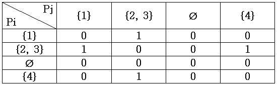
상기의 결과를 통해, 노드 1이 연결된 회선과 노드 2와 노드 3이 연결된 회선 사이에 브리지가 존재함을 알 수 있다. 또한 노드 2와 노드 3이 연결된 회선과 노드 4가 연결된 회선 사이에도 브리지가 존재함을 알 수 있다. 행렬 B를 통해 어떤 브리지가 어떤 회선 사이에 존재하는지에 대한 위상 정보를 알 수 있다. 또한 전술한 P를 통해 어떤 노드들이 같은 회선에 연결되었는지 알 수 있으므로, P와 B를 통해서 노드와 브리지들의 위상 정보를 알 수 있다.From the above result, it can be seen that a bridge exists between the circuit to which
도 5와 도 6에서 살펴본 알고리즘은 노드간의 회선 연결을 살펴보기 위한 일 실시예로서의 알고리즘이며 도 5와 도 6에 개시되지 않은 다른 방법으로도 다양하게 구현될 수 있다.The algorithms described with reference to FIGS. 5 and 6 are algorithms as an example for examining circuit connections between nodes, and may be variously implemented in other methods not disclosed in FIGS. 5 and 6.
도 7은 본 발명의 일 실시예에 따른 마스터에서의 작업의 순서를 보여주는 순서도이다. 우선 마스터가 되는 노드가 정해져야 한다. 이는 특정 노드가 될 수 있으며, 또는 사용자의 지정에 의해 계속 변경될 수도 있다. 마스터는 모드 변경을 요청하는 시작 메시지를 전체 노드에 송신한다(S110). 이는 브로드캐스트(Broadcast) 방식으로 송신하여 다른 노드들의 MAC 주소를 몰라도 전송이 되도록 한다. 시작 메시지를 받은 노드들은 자신의 수신 모드를 전패킷 수신 모드(Promiscuous mode)로 전환한다. 이렇게 함으로써, 노드들은 자신이 결합한 회선을 통과하는 모든 패킷을 수신할 수 있다. 7 is a flow chart showing the sequence of operations in the master according to an embodiment of the present invention. First, the node to be master must be determined. This may be a particular node or may continue to change by user specification. The master transmits a start message requesting a mode change to all nodes (S110). This is transmitted in a broadcast manner so that transmission is performed without knowing the MAC addresses of other nodes. Nodes receiving the start message switch their receive mode to promiscuous mode. By doing this, the nodes can receive all packets passing through the circuit to which they have joined.
마스터가 되는 노드는 체크 메시지를 송신한다(S112). 이 때, 체크 메시지는 유니캐스트(unicast)로 하여, 한 노드에 하나의 체크 메시지를 보낸다. 유니캐스트로 보낸다는 것은 하나의 노드만을 수신자로 하여 메시지를 보냄을 의미한다. 그런데, 모든 노드들이 전패킷 수신 모드로 전환하였으므로, 자신의 회선에 결합된 다른 노드를 수신자로 하는 체크 메시지도 수신할 수 있다. 이렇게 전체 노드들에 대해 각각 유니캐스트로 체크 메시지를 보내면, 각 노드들은 자신을 수신자로 하거나, 혹은 자신이 결합된 또는 연결된 회선의 다른 노드를 수신자로 하는 체크 메시지를 수신할 수 있으며, 자신이 수신한 체크 메시지의 수신자 정보를 취합하여 수신노드 정보를 생성한다. The node serving as the master transmits a check message (S112). At this time, the check message is unicast, and one check message is sent to one node. Sending unicast means sending a message with only one node as the receiver. However, since all nodes have switched to the full packet reception mode, it is also possible to receive a check message to the other node coupled to its line as a receiver. By sending a check message in unicast to each of these nodes, each node can receive a check message to itself as a receiver, or to another node on its combined or connected line, and receive it. Receive node information is generated by collecting recipient information of one check message.
마스터는 다른 노드들로부터 이 수신노드 정보를 수신한다(S114). 수신노드 정보의 일 실시예로 도 4에서의 Si이다. 그리고 수신노드 정보에서 마스터는 결합 정보를 계산한다(S116). 결합정보의 일 실시예로는 도 5의 알고리즘을 통해 얻은 Pi 이다. 마지막으로 마스터는 수신노드 정보와 결합정보에서 노드들과 브리지의 위상 정보를 추출한다(S118). S118 과정은 도 6의 알고리즘을 일 실시예로 한다.The master receives this receiving node information from other nodes (S114). One embodiment of the reception node information is Si in FIG. In operation S116, the master calculates combined information from the received node information. One embodiment of the combined information is P i obtained through the algorithm of FIG. 5. Finally, the master extracts topology information of nodes and bridges from the received node information and the combined information (S118). The process S118 uses the algorithm of FIG. 6 as an embodiment.
도 7은 하나의 노드가 마스터가 되어 시작 메시지를 송신하고, 체크 메시지를 송신하며, 그 결과를 수신하여 위상 정보를 추출하는 과정을 모두 수행하고 있 다. 그러나 이는 반드시 하나의 노드에서 수행될 필요는 없다. 예를 들어, 제 1 노드가 특정 시간에 시작 메시지를 송신하면서, 시작 메시지 내에 체크 메시지를 보낼 제 2 노드를 지정한다. 그러면 다른 노드들이 전패킷 수신 모드로 변경한 후에, 제 2 노드가 체크 메시지를 보낼 수 있다. 또한, 이 체크 메시지를 수신하여 각 노드들이 생성한 수신노드 정보 역시 제 3 노드에 전송하여 제 3 노드가 계산을 수행할 수 있다. 이는 체크 메시지 또는 시작 메시지에 제 3 노드의 IP 또는 식별 정보를 포함시킴으로써 가능하다. 따라서, 도 7에서 살펴본 과정은 하나 이상의 노드에서 나누어 수행할 수 있다.In FIG. 7, one node becomes a master, transmits a start message, transmits a check message, receives the result, and extracts phase information. However, this does not necessarily have to be done on one node. For example, while the first node sends a start message at a particular time, it designates a second node to send a check message within the start message. The second node may then send a check message after other nodes change to full packet receive mode. In addition, the node receives the check message and transmits received node information generated by each node to the third node so that the third node can perform the calculation. This is possible by including the IP or identification information of the third node in the check message or the start message. Therefore, the process described with reference to FIG. 7 may be divided and performed in one or more nodes.
또한, 시작 메시지의 전송을 필요로 하지 않을 수 있다. 일정 시간에 위상 정보를 얻도록 각 노드들을 설정할 수 있다. 그러면 일정 시간이 되면 모든 노드들이 자동으로 전패킷 수신 모드로 변경한 뒤, 마스터가 되는 노드가 체크 메시지를 보낸다. 그리고 체크 메시지를 수신한 각 노드들로부터 수신노드 정보를 수신하여 도 7의 S116, S118 과정을 수행할 수 있다.It may also not require the transmission of a start message. Each node may be set to obtain phase information at a certain time. Then, after a certain time, all nodes automatically change to full packet reception mode, and the master node sends a check message. In addition, receiving node information from each node receiving the check message may perform processes S116 and S118 of FIG. 7.
도 8은 본 발명의 일 실시예에 따른 네트워크 위상 정보를 추출하는 네트워크 장치의 구성도이다.8 is a configuration diagram of a network device for extracting network topology information according to an embodiment of the present invention.
본 실시예에서 사용되는 '~부'라는 용어, 즉 '~모듈' 또는 '~테이블' 등은 소프트웨어, FPGA 또는 ASIC과 같은 하드웨어 구성요소를 의미하며, 모듈은 어떤 기능들을 수행한다. 그렇지만 모듈은 소프트웨어 또는 하드웨어에 한정되는 의미는 아니다. 모듈은 어드레싱할 수 있는 저장 매체에 있도록 구성될 수도 있고 하나 또는 그 이상의 프로세서들을 재생시키도록 구성될 수도 있다. 따라서, 일 예로서 모 듈은 소프트웨어 구성요소들, 객체지향 소프트웨어 구성요소들, 클래스 구성요소들 및 태스크 구성요소들과 같은 구성요소들과, 프로세스들, 함수들, 속성들, 프로시저들, 서브루틴들, 프로그램 코드의 세그먼트들, 드라이버들, 펌웨어, 마이크로코드, 회로, 데이터, 데이터베이스, 데이터 구조들, 테이블들, 어레이들, 및 변수들을 포함한다. 구성요소들과 모듈들 안에서 제공되는 기능은 더 작은 수의 구성요소들 및 모듈들로 결합되거나 추가적인 구성요소들과 모듈들로 더 분리될 수 있다. 뿐만 아니라, 구성요소들 및 모듈들은 디바이스 내의 하나 또는 그 이상의 CPU들을 재생시키도록 구현될 수도 있다.The term '~ part' used in this embodiment, that is, '~ module' or '~ table' means a hardware component such as software, FPGA or ASIC, and the module performs certain functions. However, modules are not meant to be limited to software or hardware. The module may be configured to be in an addressable storage medium and may be configured to play one or more processors. Thus, as an example, a module may include components such as software components, object-oriented software components, class components, and task components, as well as processes, functions, properties, procedures, and subs. Routines, segments of program code, drivers, firmware, microcode, circuits, data, databases, data structures, tables, arrays, and variables. The functionality provided within the components and modules may be combined into a smaller number of components and modules or further separated into additional components and modules. In addition, the components and modules may be implemented to reproduce one or more CPUs in a device.
네트워크 장치는 다른 장치와 데이터를 송수신하는 것이 가능한 장치를 의미한다. 여기에는 컴퓨터, 노트북, PDA, 팩스 등의 통신이 주된 기능인 경우 외에도, 홈 네트워크를 구성하는 냉장고, 텔레비전, 전자레인지 등도 통신을 위한 기능을 갖추는 경우 네트워크 장치에 해당한다. 그리고 네트워크 장치는 전술한 노드를 의미한다. 네트워크 장치(200)는 메시지 생성부(291), 송신부(292), 수신부(293), 결합 정보 계산부(294) 및 위상 정보 추출부(295)를 포함한다.The network device refers to a device capable of transmitting and receiving data with another device. In addition to the case where communication of a computer, a notebook, a PDA, a fax, etc. are the main functions, a refrigerator, a television, a microwave oven, etc. constituting a home network also correspond to a network device. In addition, the network device means the aforementioned node. The
메시지 생성부(291)는 다른 노드에게 위상 추출을 위해 모드를 변경할 것을 요청하는 시작 메시지와 각 노드들에게 보낼 체크 메시지를 생성한다. 송신부(292)는 생성된 메시지를 다른 노드들에게 보낸다. 일 실시예로 모드 변경을 요청하는 시작 메시지는 브로드캐스트(broadcast) 방식으로 보내어 모든 노드가 시작 메시지를 수신할 수 있게 한다. 한편 각 노드들에게 보내질 체크 메시지는 유니캐스트(unicast)로 보내어, 수신자로 지정된 노드만이 수신하도록 할 수 있다. 다만, 본 발명의 일 실시예에 따라 전패킷 수신모드로 변경된 노드들은 같은 회선에 결합한 다른 노드를 수신자로 하는 체크 메시지를 수신할 수 있다. The
수신부(293)는 체크 메시지를 수신한 노드들이 생성하여 전송하는 수신노드 정보를 수신하여 이를 결합 정보 계산부(294)로 전달한다. 결합 정보 계산부(294)는 수신노드 정보를 통해 어떤 노드들이 하나의 회선에 결합되었는지를 계산한다. 일 실시예로 도 5에서 살펴본 알고리즘을 수행할 수 있다.The receiving
각 노드들이 결합된 정보를 얻게되면, 위상 정보 추출부(295)는 브리지와 노드들 간의 위상 정보를 추출한다. 위상 정보는 브리지가 어떤 노드들의 결합 사이에 존재하는지, 그리고 어떤 노드들이 어떤 브리지에 연결되어 있는지 등의 정보를 의미한다.When each node obtains the combined information, the
도 8은 시작 메시지와 체크 메시지를 송신하는 마스터가 위상 정보를 계산하는 역할도 수행하는 경우의 일 실시예이다. 만약 마스터가 시작 메시지와 체크 메시지를 보내면서, 상기 체크 메시지를 수신하여 위상 정보를 추출할 노드를 지정하거나 미리 정해져 있는 경우에는 메시지 생성부(291)를 포함하지 않을 수 있다.FIG. 8 illustrates an embodiment in which the master transmitting the start message and the check message also calculates phase information. If the master sends the start message and the check message, the node may receive the check message and designate a node to extract the phase information, or the
본 발명이 속하는 기술분야의 통상의 지식을 가진 자는 본 발명이 그 기술적 사상이나 필수적인 특징을 변경하지 않고서 다른 구체적인 형태로 실시될 수 있다는 것을 이해할 수 있을 것이다. 그러므로 이상에서 기술한 실시예들은 모든 면에서 예시적인 것이며 한정적이 아닌 것으로 이해해야만 한다. 본 발명의 범위는 상기 상세한 설명보다는 후술하는 특허청구의 범위에 의하여 나타내어지며, 특허청구의 범위의 의미 및 범위 그리고 그 균등 개념으로부터 도출되는 모든 변경 또는 변 형된 형태가 본 발명의 범위에 포함되는 것으로 해석되어야 한다.Those skilled in the art will appreciate that the present invention can be embodied in other specific forms without changing the technical spirit or essential features of the present invention. Therefore, it should be understood that the embodiments described above are exemplary in all respects and not restrictive. The scope of the present invention is indicated by the scope of the claims, which will be described later rather than the detailed description, and all changes or modifications derived from the meaning and scope of the claims and the equivalent concept are included in the scope of the present invention. Should be interpreted.
본 발명을 구현함으로써 네트워크를 구성하는 브리지와 노드의 위상 정보를 검출할 수 있다.By implementing the present invention, it is possible to detect topology information of bridges and nodes constituting the network.
본 발명을 구현함으로써 홈 네트워크와 같은 소규모 네트워크에 존재하는 브리지에 복잡한 프로토콜을 부가하지 않고 네트워크를 관리할 수 있다.By implementing the present invention, the network can be managed without adding complicated protocols to bridges existing in small networks such as home networks.
Claims (24)
Priority Applications (6)
| Application Number | Priority Date | Filing Date | Title |
|---|---|---|---|
| KR1020050029096A KR100714690B1 (en) | 2005-04-07 | 2005-04-07 | Method and apparatus for detecting topology of nodes and bridges in network |
| JP2006088663A JP4242876B2 (en) | 2005-04-07 | 2006-03-28 | Phase detection method and apparatus for nodes and bridges constituting network |
| DE602006004634T DE602006004634D1 (en) | 2005-04-07 | 2006-03-28 | Method and device for detection of network topology |
| EP06111862A EP1710958B1 (en) | 2005-04-07 | 2006-03-28 | Method and apparatus for detecting topology of network |
| CNB2006100731318A CN100490394C (en) | 2005-04-07 | 2006-04-06 | Method and apparatus for detecting topology of network |
| US11/398,604 US20060250984A1 (en) | 2005-04-07 | 2006-04-06 | Method and apparatus for detecting topology of network |
Applications Claiming Priority (1)
| Application Number | Priority Date | Filing Date | Title |
|---|---|---|---|
| KR1020050029096A KR100714690B1 (en) | 2005-04-07 | 2005-04-07 | Method and apparatus for detecting topology of nodes and bridges in network |
Publications (2)
| Publication Number | Publication Date |
|---|---|
| KR20060107094A KR20060107094A (en) | 2006-10-13 |
| KR100714690B1 true KR100714690B1 (en) | 2007-05-04 |
Family
ID=36728423
Family Applications (1)
| Application Number | Title | Priority Date | Filing Date |
|---|---|---|---|
| KR1020050029096A Expired - Fee Related KR100714690B1 (en) | 2005-04-07 | 2005-04-07 | Method and apparatus for detecting topology of nodes and bridges in network |
Country Status (6)
| Country | Link |
|---|---|
| US (1) | US20060250984A1 (en) |
| EP (1) | EP1710958B1 (en) |
| JP (1) | JP4242876B2 (en) |
| KR (1) | KR100714690B1 (en) |
| CN (1) | CN100490394C (en) |
| DE (1) | DE602006004634D1 (en) |
Families Citing this family (9)
| Publication number | Priority date | Publication date | Assignee | Title |
|---|---|---|---|---|
| US8533253B2 (en) * | 2005-06-09 | 2013-09-10 | Whirlpool Corporation | Distributed object-oriented appliance control system |
| CN102123044B (en) * | 2011-01-14 | 2013-08-28 | 北京邮电大学 | Detection device and method of network topology consistency based on topology discovery technology |
| US9300491B2 (en) | 2011-02-11 | 2016-03-29 | Qualcomm Incorporated | Frame delivery path selection in hybrid communication networks |
| US8897169B2 (en) * | 2011-03-02 | 2014-11-25 | Qualcomm Incorporated | Discovery of conventional devices and bridges in hybrid communication networks |
| US9007955B1 (en) * | 2011-03-08 | 2015-04-14 | Symantec Corporation | Systems and methods for mapping network topologies |
| US20150046826A1 (en) * | 2013-08-08 | 2015-02-12 | Alcatel Lucent Canada, Inc. | Visual Rendering of Diameter Network Topology |
| CN104518927A (en) * | 2014-12-15 | 2015-04-15 | 清华大学 | Detecting method and device of error connection in data center network |
| US12284055B2 (en) * | 2020-04-10 | 2025-04-22 | Fuji Corporation | Communication system and work apparatus |
| CN114240442B (en) * | 2021-12-01 | 2025-08-29 | 北京达佳互联信息技术有限公司 | Resource transfer data verification method, device, electronic device and storage medium |
Citations (4)
| Publication number | Priority date | Publication date | Assignee | Title |
|---|---|---|---|---|
| KR200329512Y1 (en) * | 2003-07-19 | 2003-10-10 | 한경환 | Supporting device of panel for the bones of a deceased person custody stand |
| KR20040102201A (en) * | 2002-05-01 | 2004-12-03 | 메시네트웍스, 인코포레이티드 | A system and method for using an ad-hoc routing algorithm based on activity detection in an ad-hoc network |
| KR20050000642A (en) * | 2003-06-24 | 2005-01-06 | 삼성전자주식회사 | Efficient Path Selecting Method Between Network Nodes |
| KR200491675Y1 (en) * | 2018-03-26 | 2020-05-18 | 강상길 | Moving type device for watering |
Family Cites Families (9)
| Publication number | Priority date | Publication date | Assignee | Title |
|---|---|---|---|---|
| US5226120A (en) * | 1990-05-21 | 1993-07-06 | Synoptics Communications, Inc. | Apparatus and method of monitoring the status of a local area network |
| US5546540A (en) * | 1991-01-14 | 1996-08-13 | Concord Communications, Inc. | Automatic topology monitor for multi-segment local area network |
| US5293635A (en) * | 1991-04-30 | 1994-03-08 | Hewlett-Packard Company | Detection on a network by a mapping application of a relative location of a first device to a second device |
| US5734824A (en) * | 1993-02-10 | 1998-03-31 | Bay Networks, Inc. | Apparatus and method for discovering a topology for local area networks connected via transparent bridges |
| GB9625020D0 (en) * | 1996-11-29 | 1997-01-15 | Northern Telecom Ltd | Network restoration |
| US6374316B1 (en) * | 1999-03-19 | 2002-04-16 | Sony Corporation | Method and system for circumscribing a topology to form ring structures |
| US7039696B1 (en) * | 2000-10-31 | 2006-05-02 | Hewlett-Packard Development Company, L.P. | Method and system for processing data for network connections |
| DE10146550A1 (en) * | 2001-09-21 | 2003-04-24 | Siemens Ag | Method for the automated acquisition of topological data of a communication network, switching nodes, headend, control program for switching nodes and control program for headend |
| EP1387527A1 (en) * | 2002-07-30 | 2004-02-04 | Agilent Technologies Inc. | Identifying network routers and paths |
-
2005
- 2005-04-07 KR KR1020050029096A patent/KR100714690B1/en not_active Expired - Fee Related
-
2006
- 2006-03-28 JP JP2006088663A patent/JP4242876B2/en not_active Expired - Fee Related
- 2006-03-28 DE DE602006004634T patent/DE602006004634D1/en active Active
- 2006-03-28 EP EP06111862A patent/EP1710958B1/en not_active Ceased
- 2006-04-06 US US11/398,604 patent/US20060250984A1/en not_active Abandoned
- 2006-04-06 CN CNB2006100731318A patent/CN100490394C/en not_active Expired - Fee Related
Patent Citations (4)
| Publication number | Priority date | Publication date | Assignee | Title |
|---|---|---|---|---|
| KR20040102201A (en) * | 2002-05-01 | 2004-12-03 | 메시네트웍스, 인코포레이티드 | A system and method for using an ad-hoc routing algorithm based on activity detection in an ad-hoc network |
| KR20050000642A (en) * | 2003-06-24 | 2005-01-06 | 삼성전자주식회사 | Efficient Path Selecting Method Between Network Nodes |
| KR200329512Y1 (en) * | 2003-07-19 | 2003-10-10 | 한경환 | Supporting device of panel for the bones of a deceased person custody stand |
| KR200491675Y1 (en) * | 2018-03-26 | 2020-05-18 | 강상길 | Moving type device for watering |
Also Published As
| Publication number | Publication date |
|---|---|
| EP1710958B1 (en) | 2009-01-07 |
| EP1710958A2 (en) | 2006-10-11 |
| EP1710958A3 (en) | 2006-10-25 |
| KR20060107094A (en) | 2006-10-13 |
| CN1845511A (en) | 2006-10-11 |
| JP4242876B2 (en) | 2009-03-25 |
| US20060250984A1 (en) | 2006-11-09 |
| CN100490394C (en) | 2009-05-20 |
| DE602006004634D1 (en) | 2009-02-26 |
| JP2006295917A (en) | 2006-10-26 |
Similar Documents
| Publication | Publication Date | Title |
|---|---|---|
| US7701936B2 (en) | Obtaining path information related to a bridged network | |
| US6538997B1 (en) | Layer-2 trace method and node | |
| CN103166876B (en) | Data transmission method for uplink and device between OpenFlow network domains | |
| JP5069356B2 (en) | Techniques for address resolution in data transmission networks. | |
| US6795403B1 (en) | Automatic discovery of switch devices in a network | |
| EP1891526B1 (en) | System and methods for providing a network path verification protocol | |
| US7171504B2 (en) | Transmission unit | |
| EP1811724B1 (en) | Determining data link (L2) network paths | |
| EP3934183B1 (en) | Service function chain sfc-based communication methods, and apparatuses | |
| JP2011501537A (en) | Operation status monitoring using IP network and Ethernet OAM | |
| US20180139173A1 (en) | Method and apparatus for implementing a fibre channel zone policy | |
| JP2007129702A (en) | Method and system for discovering and providing near real-time updates of VPN topology | |
| US12212488B2 (en) | Discovering a reverse path for initiating bidirectional forwarding detection (BFD) | |
| CN101115071B (en) | Apparatus and method for UPNP service in public network environment | |
| KR100714690B1 (en) | Method and apparatus for detecting topology of nodes and bridges in network | |
| JP2022160653A (en) | Packet processing methods and gateway devices | |
| WO2017000802A1 (en) | Service fault location method and device | |
| US20080298258A1 (en) | Information transfer capability discovery apparatus and techniques | |
| CN104702478B (en) | Method and device for processing virtual routing and forwarding instances | |
| CN104168132B (en) | Method for diagnosing faults, equipment and system | |
| CN114531392B (en) | Multicast service design method, server and storage medium | |
| US8228823B2 (en) | Avoiding high-speed network partitions in favor of low-speed links | |
| CN115776459A (en) | Message processing method, node, network, electronic device and storage medium | |
| WO2009067909A1 (en) | A method, network node device and system for configuring a squelch table automatically | |
| CN104885417A (en) | Control apparatus, communication system, communication node control method and program |
Legal Events
| Date | Code | Title | Description |
|---|---|---|---|
| A201 | Request for examination | ||
| PA0109 | Patent application |
St.27 status event code: A-0-1-A10-A12-nap-PA0109 |
|
| PA0201 | Request for examination |
St.27 status event code: A-1-2-D10-D11-exm-PA0201 |
|
| PN2301 | Change of applicant |
St.27 status event code: A-3-3-R10-R13-asn-PN2301 St.27 status event code: A-3-3-R10-R11-asn-PN2301 |
|
| PN2301 | Change of applicant |
St.27 status event code: A-3-3-R10-R13-asn-PN2301 St.27 status event code: A-3-3-R10-R11-asn-PN2301 |
|
| E902 | Notification of reason for refusal | ||
| PE0902 | Notice of grounds for rejection |
St.27 status event code: A-1-2-D10-D21-exm-PE0902 |
|
| PG1501 | Laying open of application |
St.27 status event code: A-1-1-Q10-Q12-nap-PG1501 |
|
| P11-X000 | Amendment of application requested |
St.27 status event code: A-2-2-P10-P11-nap-X000 |
|
| P13-X000 | Application amended |
St.27 status event code: A-2-2-P10-P13-nap-X000 |
|
| E701 | Decision to grant or registration of patent right | ||
| PE0701 | Decision of registration |
St.27 status event code: A-1-2-D10-D22-exm-PE0701 |
|
| GRNT | Written decision to grant | ||
| PR0701 | Registration of establishment |
St.27 status event code: A-2-4-F10-F11-exm-PR0701 |
|
| PR1002 | Payment of registration fee |
St.27 status event code: A-2-2-U10-U11-oth-PR1002 Fee payment year number: 1 |
|
| PG1601 | Publication of registration |
St.27 status event code: A-4-4-Q10-Q13-nap-PG1601 |
|
| PR1001 | Payment of annual fee |
St.27 status event code: A-4-4-U10-U11-oth-PR1001 Fee payment year number: 4 |
|
| PR1001 | Payment of annual fee |
St.27 status event code: A-4-4-U10-U11-oth-PR1001 Fee payment year number: 5 |
|
| FPAY | Annual fee payment | ||
| PR1001 | Payment of annual fee |
St.27 status event code: A-4-4-U10-U11-oth-PR1001 Fee payment year number: 6 |
|
| R18-X000 | Changes to party contact information recorded |
St.27 status event code: A-5-5-R10-R18-oth-X000 |
|
| FPAY | Annual fee payment | ||
| PR1001 | Payment of annual fee |
St.27 status event code: A-4-4-U10-U11-oth-PR1001 Fee payment year number: 7 |
|
| PR1001 | Payment of annual fee |
St.27 status event code: A-4-4-U10-U11-oth-PR1001 Fee payment year number: 8 |
|
| PR1001 | Payment of annual fee |
St.27 status event code: A-4-4-U10-U11-oth-PR1001 Fee payment year number: 9 |
|
| FPAY | Annual fee payment |
Payment date: 20160330 Year of fee payment: 10 |
|
| PR1001 | Payment of annual fee |
St.27 status event code: A-4-4-U10-U11-oth-PR1001 Fee payment year number: 10 |
|
| LAPS | Lapse due to unpaid annual fee | ||
| PC1903 | Unpaid annual fee |
St.27 status event code: A-4-4-U10-U13-oth-PC1903 Not in force date: 20170428 Payment event data comment text: Termination Category : DEFAULT_OF_REGISTRATION_FEE |
|
| PC1903 | Unpaid annual fee |
St.27 status event code: N-4-6-H10-H13-oth-PC1903 Ip right cessation event data comment text: Termination Category : DEFAULT_OF_REGISTRATION_FEE Not in force date: 20170428 |
|
| P22-X000 | Classification modified |
St.27 status event code: A-4-4-P10-P22-nap-X000 |