KR100712420B1 - Gripper and Grip Device with Him - Google Patents
Gripper and Grip Device with Him Download PDFInfo
- Publication number
- KR100712420B1 KR100712420B1 KR1020060048832A KR20060048832A KR100712420B1 KR 100712420 B1 KR100712420 B1 KR 100712420B1 KR 1020060048832 A KR1020060048832 A KR 1020060048832A KR 20060048832 A KR20060048832 A KR 20060048832A KR 100712420 B1 KR100712420 B1 KR 100712420B1
- Authority
- KR
- South Korea
- Prior art keywords
- groove
- gripper
- grip
- air
- air flow
- Prior art date
- Legal status (The legal status is an assumption and is not a legal conclusion. Google has not performed a legal analysis and makes no representation as to the accuracy of the status listed.)
- Expired - Fee Related
Links
Images


Classifications
-
- C—CHEMISTRY; METALLURGY
- C12—BIOCHEMISTRY; BEER; SPIRITS; WINE; VINEGAR; MICROBIOLOGY; ENZYMOLOGY; MUTATION OR GENETIC ENGINEERING
- C12M—APPARATUS FOR ENZYMOLOGY OR MICROBIOLOGY; APPARATUS FOR CULTURING MICROORGANISMS FOR PRODUCING BIOMASS, FOR GROWING CELLS OR FOR OBTAINING FERMENTATION OR METABOLIC PRODUCTS, i.e. BIOREACTORS OR FERMENTERS
- C12M23/00—Constructional details, e.g. recesses, hinges
- C12M23/02—Form or structure of the vessel
- C12M23/04—Flat or tray type, drawers
-
- C—CHEMISTRY; METALLURGY
- C12—BIOCHEMISTRY; BEER; SPIRITS; WINE; VINEGAR; MICROBIOLOGY; ENZYMOLOGY; MUTATION OR GENETIC ENGINEERING
- C12M—APPARATUS FOR ENZYMOLOGY OR MICROBIOLOGY; APPARATUS FOR CULTURING MICROORGANISMS FOR PRODUCING BIOMASS, FOR GROWING CELLS OR FOR OBTAINING FERMENTATION OR METABOLIC PRODUCTS, i.e. BIOREACTORS OR FERMENTERS
- C12M33/00—Means for introduction, transport, positioning, extraction, harvesting, peeling or sampling of biological material in or from the apparatus
- C12M33/04—Means for introduction, transport, positioning, extraction, harvesting, peeling or sampling of biological material in or from the apparatus by injection or suction, e.g. using pipettes, syringes, needles
Landscapes
- Health & Medical Sciences (AREA)
- Life Sciences & Earth Sciences (AREA)
- Organic Chemistry (AREA)
- Engineering & Computer Science (AREA)
- Bioinformatics & Cheminformatics (AREA)
- Chemical & Material Sciences (AREA)
- Zoology (AREA)
- Wood Science & Technology (AREA)
- Sustainable Development (AREA)
- Microbiology (AREA)
- Biotechnology (AREA)
- Biomedical Technology (AREA)
- Biochemistry (AREA)
- General Engineering & Computer Science (AREA)
- General Health & Medical Sciences (AREA)
- Genetics & Genomics (AREA)
- Molecular Biology (AREA)
- Clinical Laboratory Science (AREA)
- Manipulator (AREA)
Abstract
본 발명은 그리퍼 및 그를 구비한 그립 장치에 관한 것으로, 공기가 흡입되고 배출되는 입구(Inlet)홈과, 상기 입구홈에 연결된 채널홈과, 상기 채널홈에 연결된 그립홈이 형성되어 있는 하부 기판과; 상기 입구홈에 대응되는 관통홀이 형성되어 있고, 상기 하부 기판에 접합되어 있는 상부 기판으로 구성된다.The present invention relates to a gripper and a grip device having the same, an inlet groove through which air is sucked in and discharged, a lower substrate having a channel groove connected to the inlet groove, and a grip groove connected to the channel groove; ; The through hole corresponding to the inlet groove is formed, and consists of an upper substrate bonded to the lower substrate.
그러므로, 본 발명은 공기를 흡입 및 배출하여 그립홈에 대상물을 흡착하여 그립할 수 있고, 대상물을 쉽게 이탈시킬 수 있는 효과가 있다.Therefore, the present invention can suction and discharge the object by suction and discharge the air to grip the object in the grip groove, there is an effect that can easily detach the object.
또한, 본 발명은 그립홈의 일부 영역이 상부 기판의 끝단의 선상으로부터 돌출되어 있으면, 대상물을 그립홈에 안착시켜 보다 안전하게 그립할 수 있는 효과가 있다.In addition, according to the present invention, when a part of the grip groove protrudes from the line of the end of the upper substrate, the object can be gripped more securely by seating the object in the grip groove.
더불어, 본 발명은 아답터를 구비하여, 공기의 누출됨이 없이 그립퍼를 아답터를 통하여 펌프에 연결시킬 수 있는 효과가 있다. In addition, the present invention is equipped with an adapter, there is an effect that can be connected to the pump through the adapter without the leak of air.
게다가, 본 발명은 그립홈의 폭을 채널홈의 폭보다 크게 하여, 채널홈의 폭보다 큰 대상물을 원활하게 흡착하여 그립할 수 있는 효과가 있다.In addition, the present invention has the effect of making the width of the grip groove larger than the width of the channel groove, so as to smoothly attract and grip an object larger than the width of the channel groove.
흡착, 그리퍼, 그립홈, 아답터, 폭 Suction, Gripper, Grip Groove, Adapter, Width
Description
도 1은 종래 기술에 따른 마이크로 그리퍼의 개략적인 사시도1 is a schematic perspective view of a micro gripper according to the prior art
도 2a와 2b는 종래 기술에 따른 마이크로 그리퍼의 구동 방법을 설명하기 위한 개략적인 단면도2A and 2B are schematic cross-sectional views illustrating a method of driving a micro gripper according to the related art.
도 3a와 3b는 본 발명에 따른 그리퍼의 개략적인 평면도3A and 3B are schematic plan views of grippers according to the present invention.
도 4는 본 발명에 따른 그리퍼의 개략적인 평면도4 is a schematic plan view of a gripper according to the present invention;
도 5는 본 발명에 따른 그리퍼의 하부 기판의 개략적인 평면도5 is a schematic plan view of a lower substrate of a gripper according to the present invention;
도 6a와 6b는 본 발명에 따른 그리퍼가 대상물을 그립하는 공작을 설명하기 위한 단면도6A and 6B are cross-sectional views for explaining the operation in which the gripper grips the object according to the present invention.
도 7a와 7b는 본 발명에 따른 그리퍼의 하부기판에서 개략적인 대상물을 그립한 상태를 도시한 평면도7A and 7B are plan views showing a state in which a rough object is gripped on the lower substrate of the gripper according to the present invention;
도 8은 본 발명에 따른 그리퍼의 하부기판에 형성된 그립홈의 다른 형상을 도시한 단면도Figure 8 is a cross-sectional view showing another shape of the grip groove formed in the lower substrate of the gripper according to the present invention
도 9는 본 발명에 따른 펌프와 연결하기 위한 그리퍼의 아답터를 설명하기 위한 단면도Figure 9 is a cross-sectional view for explaining the adapter of the gripper for connecting with the pump according to the invention
도 10은 본 발명에 따른 그리퍼를 갖는 그립 장치의 개략적인 단면도10 is a schematic cross-sectional view of a grip device with a gripper according to the present invention.
<도면의 주요부분에 대한 부호의 설명><Description of the symbols for the main parts of the drawings>
100 : 기판 110 : 입구(Inlet)홈100: substrate 110: inlet groove
120,121,122,123 : 채널홈 130 : 그립홈120,121,122,123: Channel groove 130: Grip groove
200 : 상부 기판 210 : 관통홀200: upper substrate 210: through hole
300,301,302 : 대상물 400 : 아답터300,301,302: Object 400: Adapter
410 : 공기 유통로 500 : 펌프410: air flow path 500: pump
510 : 공기 유통관510: air distribution pipe
본 발명은 그리퍼 및 그를 구비한 그립 장치에 관한 것으로, 보다 상세하게는 공기를 흡입 및 배출하여 그립홈에 대상물을 흡착하여 그립할 수 있고, 대상물을 쉽게 이탈시킬 수 있는 그리퍼 및 그를 구비한 그립 장치에 관한 것이다.The present invention relates to a gripper and a grip device having the same, and more particularly, a gripper and a grip device having the same, which can suck and grip an object in a grip groove by suctioning and discharging air, and can easily detach the object. It is about.
최근, 나노의 시대로 접어듦에 따라, 제작되는 소자의 크기가 점점 작아지고 있으며, 연구되는 대상 또한 점점 작아지고 있다. In recent years, as the age of nanocomposites has increased, the size of devices fabricated is becoming smaller and the objects studied are becoming smaller.
특히, 세포와 같은 생체 물질의 경우, 현재 하나의 세포를 조작하는 단계에까지 와 있는 상태이다. In particular, in the case of a biological material such as a cell, it is currently in the stage of manipulating one cell.
그러나, 이러한 미세한 물체를 조작하는 방법은 아직 기초적인 방법에 머물고 있으며, 보다 쉽고 정밀한 조작을 위한 여러 가지 연구들이 활발히 행해지고 있다. However, the method of manipulating such fine objects remains a basic method, and various studies for easier and more precise manipulation are actively conducted.
이러한 연구들 중의 하나가 바로 미세 물체를 정확한 위치에서 잡는 마이크로 그리퍼에 대한 연구이다. One such study is the study of micro grippers that hold micro-objects in the correct position.
그리퍼는 1980년대 후반 UC 버클리의 김창진 박사가 처음 만든 이후, 현재는 나노 소자를 이용한 나노 그리퍼까지 개발되고 있는 상황이다. Since the gripper was first created by Dr. Chang-Jin Kim of UC Berkeley in the late 1980s, it is now being developed as a nano gripper using nano devices.
그러나, 대부분의 그리퍼들이 두 개의 집게로 잡는 형태를 띄고 있기 때문에, 실제로 물체를 잡은 상태에서 다른 측정을 하기가 어려운 실정이다. However, since most grippers are in the form of two grips, it is difficult to make another measurement while actually holding an object.
따라서, 미세한 물체의 특성을 측정하기 위해서는, 측정이 용이한 형태로, 원하는 곳에 정확히 고정시키는 작업을 할 수 있는 그리퍼의 개발이 필요하다 할 수 있다. Therefore, in order to measure the characteristics of a fine object, it may be necessary to develop a gripper that can be fixed to a desired position in a form that is easy to measure.
현재, 전자부품의 소형 경량화가 진행됨에 따라 반도체 공정을 이용하여 미세 구조물 및 마이크로 센서나 엑츄에이터(Actuator)에 대한 개발이 진행되고 있다.At present, as miniaturization and weight reduction of electronic components are progressed, development of microstructures and micro sensors or actuators using a semiconductor process is in progress.
또한, 인체에 대한 관심이 증폭되어 바이오 셀(Bio Cell) 등을 조작하는 새로운 연구가 진행되고 있다. In addition, the interest in the human body has been amplified, and new researches for manipulating bio-cells and the like are in progress.
그러나 상기와 같은 미세 구조물이나 바이오 셀 등과 같은 물질을 이동, 고정, 조합할 수 있는 장비가 없는 실정이다. However, there is no equipment capable of moving, fixing, or combining materials such as microstructures or biocells.
따라서, 상기 미세 구조물 및 엑츄에이터 등과 같은 미소 전자부품 및 생체 용 바이오 셀 등과 같은 물질을 고정, 이동, 조합 등의 동작을 하기 위하여 정밀하게 움직일 수 있는 마이크로 그리퍼(Micro Gripper)에 대한 연구가 필요한 실정이다.Therefore, there is a need for a study on a micro gripper that can move precisely in order to fix, move, or combine materials such as microelectronic components such as the microstructures and actuators, and bio-cells for living organisms. .
한편, 마이크로 그리퍼란 마이크로 부품 조립, 초정밀 위치 제어 등을 위해 초소형 형상의 물체를 집거나 원하는 곳에 떨어뜨려 놓기 위한 기구를 말하며, 구동 방법에 따라 열(Thermal), 정전(Electrostatic), 압전(Piezoelectric), 공압(Pneumatic), 혼합(Hybrid) 구동 방식으로 나눌 수 있다. On the other hand, the micro gripper refers to a mechanism for picking up or dropping an ultra-small object or dropping it to a desired place for assembling micro parts and controlling ultra-precise position, and according to a driving method, thermal, electrostatic, and piezoelectric. It can be divided into Pneumatic and Hybrid drive.
상기 열 구동 마이크로 그리퍼는 인가하는 전압에 의해 발생되는 줄(Joule) 열에 의한 물질의 열팽창을 이용하는 방식을 이용하여 그리핑하므로, 큰 구동 전압과 에너지 소비 문제 및 바이오 분야에의 응용이 다소 어렵다는 단점이 있다.The thermally driven micro gripper grips using a method of utilizing thermal expansion of a material due to Joule heat generated by an applied voltage, so that a large driving voltage, energy consumption problem, and application to biotechnology are somewhat difficult. have.
그리고, 정전형 마이크로 그리퍼는 인가되는 두 전하 사이의 정전력을 이용하여 물체를 그리핑하는 방식으로 전압에 대한 구동 변위 및 그리핑의 힘이 작다는 단점이 있으며, 그리핑 후 물체를 놓을 때 정전력에 의한 스틱션(Stiction)으로 물체를 제대로 놓지 못하는 경우가 있다.In addition, the electrostatic micro gripper has a disadvantage in that the driving displacement with respect to the voltage and the force of the gripping are small by gripping an object by using an electrostatic force between two applied electric charges. In some cases, objects may not be properly placed due to power stiction.
또한, 압전 구동 마이크로 그리퍼는 정밀한 구동 제어 및 그리핑의 힘이 크다는 장점이 있으나, 압전 물질이 가지는 고유의 히스테리시스 형상을 최소화해야 한다는 문제점이 있다.In addition, the piezoelectric driving micro gripper has the advantage of high precision driving control and gripping force, but has a problem in that the inherent hysteresis shape of the piezoelectric material must be minimized.
상기 공압 마이크로 그리퍼는 공압을 이용하므로 전압과 같은 특별한 에너지원이 필요하지 않으며, 바이오 등과 같이 여러 가지 응용분야에 응용이 가능하다. Since the pneumatic micro gripper uses pneumatic pressure, no special energy source such as voltage is required, and the pneumatic micro gripper is applicable to various applications such as bio.
또한, 사람의 손가락 관절과 같은 형태로도 제작이 가능하므로 그리핑시 물 체를 잘 집을 수 있는 장점이 있다. In addition, since it can be manufactured in the form of a human finger joint, there is an advantage that the object can be picked up well when gripping.
그러나 물체를 그리핑시 그리핑의 힘이 적으며, 공압 제어 및 공정이 어렵고, 공기가 들어가기 위해 별도의 패키지 공정이 필요하므로 전체적으로 제조 단가가 올라가는 문제점이 있었다.However, when gripping the object, the gripping force is small, the pneumatic control and the process is difficult, and a separate packaging process is required to enter the air, there is a problem that the overall manufacturing cost increases.
도 1은 종래 기술에 따른 마이크로 그리퍼의 개략적인 사시도로서, 마이크로 그리퍼(10)는 상호 이격되어 마주보고 있는 한 쌍의 마이크로 그리퍼 조(Gripper Jaw)의 구조물(11,12)로 이루어져 있다.1 is a schematic perspective view of a micro gripper according to the prior art, in which the
이러한, 마이크로 그리퍼(10)는 엑츄에이터에 의해 그리핑(Gripping) 동작을 수행하여 미소 부품 및 바이오 셀을 정밀 조작할 수 있는 장점을 갖고 있다.Such a
이 엑츄에이터는 압전에 의하여 구동되는 방식을 주로 사용하고 있다.This actuator mainly uses a system driven by piezoelectricity.
도 2a와 2b는 종래 기술에 따른 마이크로 그리퍼의 구동 방법을 설명하기 위한 개략적인 단면도로서, 도 2a에 도시된 바와 같이, 한 쌍의 마이크로 그리퍼 조(Gripper Jaw)의 구조물(11,12)은 엑츄에이터의 구동으로 간격이 좁아져 대상물체(20)를 잡는다.2A and 2B are schematic cross-sectional views illustrating a method of driving a micro gripper according to the related art. As shown in FIG. 2A,
그 후, 한 쌍의 마이크로 그리퍼 조(Gripper Jaw)의 구조물(11,12)의 간격을 넓혀 대상물체(20)를 잡는 힘을 해제한다.Thereafter, the distance between the
이 때, 도 2b에 도시된 바와 같이, 마이크로 그리퍼는 100㎛ 이하의 물체를 잡을 경우 대상물체(20)와 그리퍼 조(Gripper Jaw)의 구조물(11,12) 사이에 정전기력(Electrostatic Force)이 발생하여 그리퍼 조의 구조물(11,12)에 대상물체(20)가 달라 붙는 스틱션 현상이 발생하게 된다.In this case, as shown in FIG. 2B, when the micro gripper catches an object of 100 μm or less, an electrostatic force is generated between the
이와 같이, 종래 기술에 따른 마이크로 그리퍼는 미소 물체를 잡거나 제어하는데 있어 어려움을 발생하여 미소 물체를 원하는 위치에 놓기가 어려운 문제점이 있었다.As described above, the micro gripper according to the related art has a problem in that it is difficult to place the micro object in a desired position due to difficulty in catching or controlling the micro object.
본 발명은 상기한 바와 같은 문제점을 해결하기 위하여, 공기를 흡입 및 배출하여 그립홈에 대상물을 흡착하여 그립할 수 있고, 대상물을 쉽게 이탈시킬 수 있는 그리퍼 및 그를 구비한 그립 장치를 제공하는 데 목적이 있다.In order to solve the problems as described above, an object of the present invention is to provide a gripper and a grip device having the same, which can suck and suck an object to a grip groove by suctioning and discharging air, and can easily detach the object. There is this.
본 발명의 다른 목적은 그립홈의 일부 영역이 상부 기판의 끝단의 선상으로부터 돌출되어 있으면, 대상물을 그립홈에 안착시켜 보다 안전하게 그립할 수 있는 그리퍼 및 그를 구비한 그립 장치를 제공하는 데 있다.Another object of the present invention is to provide a gripper and a grip device having the same, when a part of the grip groove protrudes from the line of the end of the upper substrate, the object can be gripped more securely by seating the object in the grip groove.
본 발명의 또 다른 목적은 아답터를 구비하여, 공기의 누출됨이 없이 그립퍼를 아답터를 통하여 펌프에 연결시킬 수 있는 그리퍼 및 그를 구비한 그립 장치를 제공하는 데 있다.Still another object of the present invention is to provide a gripper having an adapter, which can connect the gripper to the pump through the adapter without leaking air, and a grip device having the same.
상기한 본 발명의 목적들을 달성하기 위한 바람직한 제 1 양태(樣態)는, A first preferred aspect for achieving the above objects of the present invention is
공기가 흡입되고 배출되는 입구(Inlet)홈과, 상기 입구홈에 연결된 채널홈과, 상기 채널홈에 연결된 그립홈이 형성되어 있는 하부 기판과; A lower substrate having an inlet groove through which air is sucked in and discharged, a channel groove connected to the inlet groove, and a grip groove connected to the channel groove;
상기 입구홈에 대응되는 관통홀이 형성되어 있고, 상기 하부 기판에 접합되어 있는 상부 기판으로 구성된 그리퍼가 제공된다.A through-hole corresponding to the inlet groove is formed, and a gripper composed of an upper substrate bonded to the lower substrate is provided.
상기한 본 발명의 목적들을 달성하기 위한 바람직한 제 2 양태(樣態)는, A second preferred aspect for achieving the above objects of the present invention is
공기가 흡입되고 배출되는 입구(Inlet)홈과, 상기 입구홈에 연결된 채널홈과, 상기 채널홈에 연결된 그립홈이 형성되어 있는 하부 기판과; 상기 입구홈에 대응되는 관통홀이 형성되어 있고, 상기 하부 기판에 접합되어 있는 상부 기판으로 구성된 그리퍼와; A lower substrate having an inlet groove through which air is sucked in and discharged, a channel groove connected to the inlet groove, and a grip groove connected to the channel groove; A gripper having a through hole corresponding to the inlet groove and formed of an upper substrate bonded to the lower substrate;
상기 그리퍼의 상부 기판에 형성된 관통홀과 연통되는 공기 유통로가 형성되어 있고, 상기 공기 유통로의 일단이 상기 관통홀과 연결될 때 상기 공기 유통로의 일단 주위의 영역이 상기 상부 기판의 상부면과 접촉되고, 상기 공기 유통로의 타단이 존재하는 영역이 노즐 형상으로 형성되어 있는 아답터와; An air flow path is formed in communication with the through hole formed in the upper substrate of the gripper, and when one end of the air flow path is connected with the through hole, an area around one end of the air flow path is connected to the upper surface of the upper substrate. An adapter in contact with and formed in a nozzle shape in a region in which the other end of the air flow passage exists;
상기 아답터의 상기 공기 유통로의 타단이 존재하는 영역에 체결되어 있는 공기 유통관과; An air distribution pipe fastened to a region where the other end of the adapter exists in the air flow passage;
상기 공기 유통관과 연결되어 있는 펌프로 구성된 그리퍼를 구비한 그립 장치가 제공된다.Provided is a grip device having a gripper composed of a pump connected to the air distribution pipe.
이하, 첨부된 도면을 참조하여 본 발명의 바람직한 실시예를 설명하면 다음과 같다. Hereinafter, exemplary embodiments of the present invention will be described with reference to the accompanying drawings.
도 3a와 3b는 본 발명에 따른 그리퍼의 개략적인 평면도로서, 먼저, 공기가 흡입되고 배출되는 입구(Inlet)홈(110)과, 상기 입구홈(110)에 연결된 채널홈(120)과, 상기 채널홈(120)에 연결된 그립홈(130)이 형성되어 있는 하부 기판(100)과; 상기 입구홈(110)에 대응되는 관통홀(210)이 형성되어 있고, 상기 하부 기판(100)에 접합되어 있는 상부 기판(200)으로 구성된다.3A and 3B are schematic plan views of a gripper according to the present invention. First, an
이렇게 구성된 본 발명의 그리퍼는 상기 관통홀(210)을 통하여 공기를 흡입 및 배출하여, 상기 그립홈(130)에서 대상물을 그리핑(Gripping)하거나, 그리핑을 해제한다.The gripper of the present invention configured as described above sucks and discharges air through the through-
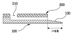
도 4는 본 발명에 따른 그리퍼의 개략적인 평면도로서, 상부 기판(200)의 관통홀(210)이 하부 기판(100)의 입구홈(110)에 연통되게 하고, 상기 상부 기판(200)을 하부 기판(100)에 접합한다.4 is a schematic plan view of a gripper according to the present invention, which allows the through
그러면, 도 4에 도시된 바와 같이, 상기 상부 기판(200)은 하부 기판(100)에 접합되어 있는 상태에서, 그립홈의 일부 영역은 상부 기판의 끝단의 선상으로부터 돌출되어 있게 된다.Then, as shown in FIG. 4, while the
이렇게, 그립홈의 일부 영역이 상부 기판의 끝단의 선상으로부터 돌출되어 있으면, 대상물을 그립홈에 안착시켜 보다 안전하게 그립할 수 있는 장점이 있다.As such, when a part of the grip groove protrudes from the line of the end of the upper substrate, there is an advantage that the object can be gripped more securely by seating the object in the grip groove.
도 5는 본 발명에 따른 그리퍼의 하부 기판의 개략적인 평면도로서, 하부 기판(100)에 형성된 채널홈(120)은 복수개의 채널홈들(121,122,123)로 분기되어 그립홈(130)에 연결되어 있다.5 is a schematic plan view of the lower substrate of the gripper according to the present invention, in which the
도 6a와 6b는 본 발명에 따른 그리퍼가 대상물을 그립하는 공작을 설명하기 위한 단면도로서, 상부 기판(200)의 관통홀(210)을 통하여 공기를 흡입하면, 하부 기판(100)의 그립홈(130), 입구홈(110)과 채널홈(120)을 통하여 외부 공기가 흡입됨으로, 도 6a에 도시된 바와 같이, 상기 그립홈(130)에서는 대상물(300)을 흡착할 수 있게 된다.6A and 6B are cross-sectional views illustrating a gripper grip operation of an object according to the present invention. When the air is sucked in through the through
그리고, 상부 기판(200)의 관통홀(210)을 통하여 공기를 배출하면, 하부 기판(100)의 그립홈(130), 입구홈(110)과 채널홈(120)을 통하여 공기가 배출됨으로, 도 6b와 같이, 대상물(300)은 상기 그립홈(130)으로부터 이탈되어, 그리퍼는 대상물(300)의 이탈 공정을 수행하게 된다.When the air is discharged through the through
도 7a와 7b는 본 발명에 따른 그리퍼의 하부기판에서 개략적인 대상물을 그립한 상태를 도시한 평면도로서, 그리퍼에 대상물이 흡착될 때, 대상물은 하부 기판(100)의 그립홈(130)의 넓은 측벽에 접촉되어 흡착됨으로써, 대상물의 그립(Grip)이 원활해진다.7A and 7B are plan views illustrating a state in which a rough object is gripped on the lower substrate of the gripper according to the present invention. When the object is adsorbed to the gripper, the object is wide in the
즉, 상기 그립홈(130)의 폭은 채널홈(120)의 폭보다 크기 때문에, 작은 채널홈(120)을 통하여 공기를 흡입하고, 상기 채널홈(120)보다 상대적으로 큰 면적의 그립홈(130)의 측벽에서 대상물을 흡착하게 된다.That is, since the width of the
그리고, 상기 그립홈(130)은 상기 채널홈(120)과 접촉되는 영역이 깔대기 형상으로 형성되어 있어, 상기 채널홈(120)의 폭보다 큰 대상물을 흡착할 수 있는 장점이 있다.In addition, the
즉, 본 발명의 그리퍼의 그립동작시, 도 7a에 도시된 바와 같은 원판 형상의 대상물(301) 및 도 7b와 같은 육각 형상의 대상물(302)은 그립홈(130)의 측벽에 흡착된다.That is, in the grip operation of the gripper of the present invention, the disk-shaped
도 8은 본 발명에 따른 그리퍼의 하부기판에 형성된 그립홈의 다른 형상을 도시한 단면도로서, 그립홈(130)의 일부 영역은 상부 기판(200)의 끝단의 선상으로 부터 돌출되어 있으며, 그 돌출된 그립홈(130) 영역의 상부는 경사져 있는 것이 바람직하다.8 is a cross-sectional view showing another shape of the grip groove formed on the lower substrate of the gripper according to the present invention, a part of the
이렇게, 돌출된 그립홈(130) 영역의 상부가 경사져 있으면, 대상물을 흡착시킬 때, 상기 그립홈(130)으로 대상물의 이동이 용이해져, 본 발명의 그리퍼는 그립 동작을 보다 쉽게 수행할 수 있게 된다.When the upper portion of the protruding
도 9는 본 발명에 따른 펌프와 연결하기 위한 그리퍼의 아답터를 설명하기 위한 단면도로서, 본 발명의 그리퍼의 구조적인 특징으로 인하여, 공기의 누출됨이 없이 상부 기판의 관통홀(210)과 펌프에 연결된 유통관을 쉽게 연결하기 위해서는 보조적인 수단이 필요하다.Figure 9 is a cross-sectional view for explaining the adapter of the gripper for connecting with the pump according to the present invention, due to the structural features of the gripper of the present invention, the through
그러므로, 그리퍼의 상부 기판(200)에 형성된 관통홀(210)과 아답터를 연결한 후, 이 아답터를 통하여 펌프에 연결하는 것이 바람직하다.Therefore, after connecting the adapter and the through-
도 9에 도시된 바와 같이, 아답터(400)는 그리퍼의 상부 기판(200)의 상부면 및 측면과 하부 기판(100)의 측면과 체결되는 구조를 가지고 있어야 되고, 아답터(400) 내부에 공기가 유통되는 통로가 있어야 바람직하다.As shown in FIG. 9, the
더불어, 펌프와 연결된 공기 유통관과의 체결을 원활하게 하기 위한 노즐 형태의 구조가 있는 것이 바람직하다.In addition, it is preferable that there is a nozzle-type structure for smoothly fastening with the air distribution pipe connected to the pump.
따라서, 상기 아답터(400)는 그리퍼의 상부 기판(200)에 형성된 관통홀(210)과 연통되는 공기 유통로(410)가 형성되어 있고, 상기 공기 유통로(410)의 일단이 상기 관통홀(210)과 연결될 때 상기 공기 유통로(410)의 일단 주위의 영역(421)이 상기 상부 기판(200)의 상부면과 접촉되고, 상기 공기 유통로(410)의 타단이 존재 하는 영역(422)이 노즐 형상으로 형성되어 있다.Accordingly, the
결과적으로, 본 발명은 아답터를 구비하여, 공기의 누출됨이 없이 그립퍼를 아답터를 통하여 펌프에 연결시킬 수 있는 장점이 있다.As a result, the present invention has the advantage that the gripper can be connected to the pump through the adapter without leaking air.
도 10은 본 발명에 따른 그리퍼를 갖는 그립 장치의 개략적인 단면도로서, 전술된 그리퍼가 구비된 그립 장치는, 공기가 흡입되고 배출되는 입구(Inlet)홈(110)과, 상기 입구홈(110)에 연결된 채널홈(120)과, 상기 채널홈(120)에 연결된 그립홈(130)이 형성되어 있는 하부 기판(100)과; 상기 입구홈(110)에 대응되는 관통홀(210)이 형성되어 있고, 상기 하부 기판(100)에 접합되어 있는 상부 기판(200)으로 구성된 그리퍼와; 상기 그리퍼의 상부 기판(200)에 형성된 관통홀(210)과 연통되는 공기 유통로(410)가 형성되어 있고, 상기 공기 유통로(410)의 일단이 상기 관통홀(210)과 연결될 때 상기 공기 유통로(410)의 일단 주위의 영역(421)이 상기 상부 기판(200)의 상부면과 접촉되고, 상기 공기 유통로(410)의 타단이 존재하는 영역(422)이 노즐 형상으로 형성되어 있는 아답터와; 상기 아답터의 상기 공기 유통로(410)의 타단이 존재하는 영역(422)에 체결되어 있는 공기 유통관(510)과; 상기 공기 유통관(510)과 연결되어 있는 펌프(500)로 구성된다.10 is a schematic cross-sectional view of a grip device having a gripper according to the present invention, wherein the grip device with a gripper described above includes an
즉, 상기 그리퍼는 아답터 및 공기 유통관(510)을 통하여 펌프(500)에 연결된다.That is, the gripper is connected to the
이상 상술한 바와 같이, 본 발명은 공기를 흡입 및 배출하여 그립홈에 대상 물을 흡착하여 그립할 수 있고, 대상물을 쉽게 이탈시킬 수 있는 효과가 있다.As described above, the present invention has the effect that the suction and discharge the air to grip the target water by the suction of the grip groove, the object can be easily separated.
또한, 본 발명은 그립홈의 일부 영역이 상부 기판의 끝단의 선상으로부터 돌출되어 있으면, 대상물을 그립홈에 안착시켜 보다 안전하게 그립할 수 있는 효과가 있다.In addition, according to the present invention, when a part of the grip groove protrudes from the line of the end of the upper substrate, the object can be gripped more securely by seating the object in the grip groove.
더불어, 본 발명은 아답터를 구비하여, 공기의 누출됨이 없이 그립퍼를 아답터를 통하여 펌프에 연결시킬 수 있는 효과가 있다. In addition, the present invention is equipped with an adapter, there is an effect that can be connected to the pump through the adapter without the leak of air.
게다가, 본 발명은 그립홈의 폭을 채널홈의 폭보다 크게 하여, 채널홈의 폭보다 큰 대상물을 원활하게 흡착하여 그립할 수 있는 효과가 있다.In addition, the present invention has the effect of making the width of the grip groove larger than the width of the channel groove, so as to smoothly attract and grip an object larger than the width of the channel groove.
본 발명은 구체적인 예에 대해서만 상세히 설명되었지만 본 발명의 기술사상 범위 내에서 다양한 변형 및 수정이 가능함은 당업자에게 있어서 명백한 것이며, 이러한 변형 및 수정이 첨부된 특허청구범위에 속함은 당연한 것이다.Although the invention has been described in detail only with respect to specific examples, it will be apparent to those skilled in the art that various modifications and variations are possible within the spirit of the invention, and such modifications and variations belong to the appended claims.
Claims (9)
Priority Applications (1)
| Application Number | Priority Date | Filing Date | Title |
|---|---|---|---|
| KR1020060048832A KR100712420B1 (en) | 2006-05-30 | 2006-05-30 | Gripper and Grip Device with Him |
Applications Claiming Priority (1)
| Application Number | Priority Date | Filing Date | Title |
|---|---|---|---|
| KR1020060048832A KR100712420B1 (en) | 2006-05-30 | 2006-05-30 | Gripper and Grip Device with Him |
Publications (1)
| Publication Number | Publication Date |
|---|---|
| KR100712420B1 true KR100712420B1 (en) | 2007-04-27 |
Family
ID=38182550
Family Applications (1)
| Application Number | Title | Priority Date | Filing Date |
|---|---|---|---|
| KR1020060048832A Expired - Fee Related KR100712420B1 (en) | 2006-05-30 | 2006-05-30 | Gripper and Grip Device with Him |
Country Status (1)
| Country | Link |
|---|---|
| KR (1) | KR100712420B1 (en) |
Cited By (1)
| Publication number | Priority date | Publication date | Assignee | Title |
|---|---|---|---|---|
| KR20190001038A (en) | 2017-06-26 | 2019-01-04 | 한양대학교 에리카산학협력단 | Device for Substrate Grip |
Citations (6)
| Publication number | Priority date | Publication date | Assignee | Title |
|---|---|---|---|---|
| JP2003225895A (en) * | 2002-01-31 | 2003-08-12 | Yoshikazu Nakayama | Diode-type nanotweezers and nanomanipulator device using the same |
| KR20040070192A (en) * | 2001-11-29 | 2004-08-06 | 가부시키가이샤 테크노 네트워크 시코쿠 | Nano gripper and method of manufacturing the nano gripper |
| US20040207219A1 (en) * | 2003-01-29 | 2004-10-21 | Gernot Schmierer | Suction grip arm |
| KR20050023483A (en) * | 2003-08-28 | 2005-03-10 | 재단법인서울대학교산학협력재단 | An improved method of intracytoplasmic sperm injection |
| KR20050105479A (en) * | 2003-02-21 | 2005-11-04 | 프라운호퍼-게젤샤프트 추르 푀르데룽 데어 안제반텐 포르슝 에 파우 | Method and devices for non-traumatic movement of a probe through biological cell material |
| KR20060013025A (en) * | 2004-08-05 | 2006-02-09 | 삼성전자주식회사 | Electrostatically Driven Nano Forceps |
-
2006
- 2006-05-30 KR KR1020060048832A patent/KR100712420B1/en not_active Expired - Fee Related
Patent Citations (6)
| Publication number | Priority date | Publication date | Assignee | Title |
|---|---|---|---|---|
| KR20040070192A (en) * | 2001-11-29 | 2004-08-06 | 가부시키가이샤 테크노 네트워크 시코쿠 | Nano gripper and method of manufacturing the nano gripper |
| JP2003225895A (en) * | 2002-01-31 | 2003-08-12 | Yoshikazu Nakayama | Diode-type nanotweezers and nanomanipulator device using the same |
| US20040207219A1 (en) * | 2003-01-29 | 2004-10-21 | Gernot Schmierer | Suction grip arm |
| KR20050105479A (en) * | 2003-02-21 | 2005-11-04 | 프라운호퍼-게젤샤프트 추르 푀르데룽 데어 안제반텐 포르슝 에 파우 | Method and devices for non-traumatic movement of a probe through biological cell material |
| KR20050023483A (en) * | 2003-08-28 | 2005-03-10 | 재단법인서울대학교산학협력재단 | An improved method of intracytoplasmic sperm injection |
| KR20060013025A (en) * | 2004-08-05 | 2006-02-09 | 삼성전자주식회사 | Electrostatically Driven Nano Forceps |
Cited By (1)
| Publication number | Priority date | Publication date | Assignee | Title |
|---|---|---|---|---|
| KR20190001038A (en) | 2017-06-26 | 2019-01-04 | 한양대학교 에리카산학협력단 | Device for Substrate Grip |
Similar Documents
| Publication | Publication Date | Title |
|---|---|---|
| Beyeler et al. | Monolithically fabricated microgripper with integrated force sensor for manipulating microobjects and biological cells aligned in an ultrasonic field | |
| Chen et al. | Active release of microobjects using a MEMS microgripper to overcome adhesion forces | |
| Kim et al. | Nanonewton force-controlled manipulation of biological cells using a monolithic MEMS microgripper with two-axis force feedback | |
| Xie et al. | High-precision automated micromanipulation and adhesive microbonding with cantilevered micropipette probes in the dynamic probing mode | |
| Savia et al. | Contact micromanipulation—Survey of strategies | |
| Peng et al. | EWOD (electrowetting on dielectric) digital microfluidics powered by finger actuation | |
| KR101014226B1 (en) | Gripper and its driving method | |
| US8919840B2 (en) | Mechanical gripper for manipulation of micro-sized objects | |
| Kim et al. | Micronewton force-controlled manipulation of biomaterials using a monolithic MEMS microgripper with two-axis force feedback | |
| CN104760928B (en) | The capillary force pickup of hydrophobic surface dropwise condensation and micro-object operation apparatus of vibration control and method | |
| US20160016318A1 (en) | Suction device | |
| WO2010094102A1 (en) | Device for grasping and active release of micro and nano objects | |
| Park et al. | A hybrid-type micro-gripper with an integrated force sensor | |
| KR100712420B1 (en) | Gripper and Grip Device with Him | |
| Lee et al. | Fabrication of an electrothermally actuated electrostatic microgripper | |
| KR100660316B1 (en) | Micro Gripper and Its Driving Method | |
| Rabenorosoa et al. | Study of forces during microassembly tasks using two-sensing-fingers grippers | |
| CN112757257B (en) | A kind of electrowetting micro-gripper and clamping method for small and micro objects | |
| Krishnan et al. | A multi-fingered micromechanism for coordinated micro/nano manipulation | |
| KR100705797B1 (en) | Adsorption type micro gripper and manufacturing method | |
| US7770951B2 (en) | Micro gripper and method for manufacturing the same | |
| Hoxhold et al. | Batch fabrication of micro grippers with integrated actuators | |
| Mayyas et al. | Design tradeoffs for electrothermal microgrippers | |
| Choi et al. | Microhand with internal visual system | |
| Otsuka et al. | Active Optical Sensor Microrobot Equipped With Multi-DoF Gripper Arm Based on Kinetic Electronics |
Legal Events
| Date | Code | Title | Description |
|---|---|---|---|
| A201 | Request for examination | ||
| PA0109 | Patent application |
St.27 status event code: A-0-1-A10-A12-nap-PA0109 |
|
| PA0201 | Request for examination |
St.27 status event code: A-1-2-D10-D11-exm-PA0201 |
|
| D13-X000 | Search requested |
St.27 status event code: A-1-2-D10-D13-srh-X000 |
|
| D14-X000 | Search report completed |
St.27 status event code: A-1-2-D10-D14-srh-X000 |
|
| E701 | Decision to grant or registration of patent right | ||
| PE0701 | Decision of registration |
St.27 status event code: A-1-2-D10-D22-exm-PE0701 |
|
| GRNT | Written decision to grant | ||
| PR0701 | Registration of establishment |
St.27 status event code: A-2-4-F10-F11-exm-PR0701 |
|
| PR1002 | Payment of registration fee |
St.27 status event code: A-2-2-U10-U11-oth-PR1002 Fee payment year number: 1 |
|
| PG1601 | Publication of registration |
St.27 status event code: A-4-4-Q10-Q13-nap-PG1601 |
|
| PR1001 | Payment of annual fee |
St.27 status event code: A-4-4-U10-U11-oth-PR1001 Fee payment year number: 4 |
|
| PR1001 | Payment of annual fee |
St.27 status event code: A-4-4-U10-U11-oth-PR1001 Fee payment year number: 5 |
|
| PR1001 | Payment of annual fee |
St.27 status event code: A-4-4-U10-U11-oth-PR1001 Fee payment year number: 6 |
|
| FPAY | Annual fee payment |
Payment date: 20130111 Year of fee payment: 7 |
|
| PR1001 | Payment of annual fee |
St.27 status event code: A-4-4-U10-U11-oth-PR1001 Fee payment year number: 7 |
|
| PN2301 | Change of applicant |
St.27 status event code: A-5-5-R10-R13-asn-PN2301 St.27 status event code: A-5-5-R10-R11-asn-PN2301 |
|
| FPAY | Annual fee payment |
Payment date: 20131231 Year of fee payment: 8 |
|
| PR1001 | Payment of annual fee |
St.27 status event code: A-4-4-U10-U11-oth-PR1001 Fee payment year number: 8 |
|
| FPAY | Annual fee payment |
Payment date: 20150109 Year of fee payment: 9 |
|
| PR1001 | Payment of annual fee |
St.27 status event code: A-4-4-U10-U11-oth-PR1001 Fee payment year number: 9 |
|
| LAPS | Lapse due to unpaid annual fee | ||
| PC1903 | Unpaid annual fee |
St.27 status event code: A-4-4-U10-U13-oth-PC1903 Not in force date: 20160424 Payment event data comment text: Termination Category : DEFAULT_OF_REGISTRATION_FEE |
|
| P22-X000 | Classification modified |
St.27 status event code: A-4-4-P10-P22-nap-X000 |
|
| PC1903 | Unpaid annual fee |
St.27 status event code: N-4-6-H10-H13-oth-PC1903 Ip right cessation event data comment text: Termination Category : DEFAULT_OF_REGISTRATION_FEE Not in force date: 20160424 |
|
| P22-X000 | Classification modified |
St.27 status event code: A-4-4-P10-P22-nap-X000 |
|
| R18-X000 | Changes to party contact information recorded |
St.27 status event code: A-5-5-R10-R18-oth-X000 |
|
| PN2301 | Change of applicant |
St.27 status event code: A-5-5-R10-R13-asn-PN2301 St.27 status event code: A-5-5-R10-R11-asn-PN2301 |
|
| PN2301 | Change of applicant |
St.27 status event code: A-5-5-R10-R13-asn-PN2301 St.27 status event code: A-5-5-R10-R11-asn-PN2301 |