KR100709860B1 - An electrode comprising a Si-containing material layer and a porous membrane and a lithium battery employing the same - Google Patents
An electrode comprising a Si-containing material layer and a porous membrane and a lithium battery employing the same Download PDFInfo
- Publication number
- KR100709860B1 KR100709860B1 KR1020050066867A KR20050066867A KR100709860B1 KR 100709860 B1 KR100709860 B1 KR 100709860B1 KR 1020050066867 A KR1020050066867 A KR 1020050066867A KR 20050066867 A KR20050066867 A KR 20050066867A KR 100709860 B1 KR100709860 B1 KR 100709860B1
- Authority
- KR
- South Korea
- Prior art keywords
- group
- carbon atoms
- electrode
- material layer
- och
- Prior art date
- Legal status (The legal status is an assumption and is not a legal conclusion. Google has not performed a legal analysis and makes no representation as to the accuracy of the status listed.)
- Expired - Fee Related
Links
Images


Classifications
-
- H—ELECTRICITY
- H01—ELECTRIC ELEMENTS
- H01M—PROCESSES OR MEANS, e.g. BATTERIES, FOR THE DIRECT CONVERSION OF CHEMICAL ENERGY INTO ELECTRICAL ENERGY
- H01M4/00—Electrodes
- H01M4/02—Electrodes composed of, or comprising, active material
- H01M4/62—Selection of inactive substances as ingredients for active masses, e.g. binders, fillers
-
- H—ELECTRICITY
- H01—ELECTRIC ELEMENTS
- H01M—PROCESSES OR MEANS, e.g. BATTERIES, FOR THE DIRECT CONVERSION OF CHEMICAL ENERGY INTO ELECTRICAL ENERGY
- H01M4/00—Electrodes
- H01M4/02—Electrodes composed of, or comprising, active material
- H01M4/13—Electrodes for accumulators with non-aqueous electrolyte, e.g. for lithium-accumulators; Processes of manufacture thereof
- H01M4/134—Electrodes based on metals, Si or alloys
-
- H—ELECTRICITY
- H01—ELECTRIC ELEMENTS
- H01M—PROCESSES OR MEANS, e.g. BATTERIES, FOR THE DIRECT CONVERSION OF CHEMICAL ENERGY INTO ELECTRICAL ENERGY
- H01M10/00—Secondary cells; Manufacture thereof
- H01M10/05—Accumulators with non-aqueous electrolyte
- H01M10/052—Li-accumulators
- H01M10/0525—Rocking-chair batteries, i.e. batteries with lithium insertion or intercalation in both electrodes; Lithium-ion batteries
-
- H—ELECTRICITY
- H01—ELECTRIC ELEMENTS
- H01M—PROCESSES OR MEANS, e.g. BATTERIES, FOR THE DIRECT CONVERSION OF CHEMICAL ENERGY INTO ELECTRICAL ENERGY
- H01M10/00—Secondary cells; Manufacture thereof
- H01M10/42—Methods or arrangements for servicing or maintenance of secondary cells or secondary half-cells
- H01M10/4235—Safety or regulating additives or arrangements in electrodes, separators or electrolyte
-
- H—ELECTRICITY
- H01—ELECTRIC ELEMENTS
- H01M—PROCESSES OR MEANS, e.g. BATTERIES, FOR THE DIRECT CONVERSION OF CHEMICAL ENERGY INTO ELECTRICAL ENERGY
- H01M10/00—Secondary cells; Manufacture thereof
- H01M10/42—Methods or arrangements for servicing or maintenance of secondary cells or secondary half-cells
- H01M10/52—Removing gases inside the secondary cell, e.g. by absorption
-
- H—ELECTRICITY
- H01—ELECTRIC ELEMENTS
- H01M—PROCESSES OR MEANS, e.g. BATTERIES, FOR THE DIRECT CONVERSION OF CHEMICAL ENERGY INTO ELECTRICAL ENERGY
- H01M4/00—Electrodes
- H01M4/02—Electrodes composed of, or comprising, active material
- H01M4/64—Carriers or collectors
- H01M4/66—Selection of materials
- H01M4/665—Composites
- H01M4/667—Composites in the form of layers, e.g. coatings
-
- H—ELECTRICITY
- H01—ELECTRIC ELEMENTS
- H01M—PROCESSES OR MEANS, e.g. BATTERIES, FOR THE DIRECT CONVERSION OF CHEMICAL ENERGY INTO ELECTRICAL ENERGY
- H01M50/00—Constructional details or processes of manufacture of the non-active parts of electrochemical cells other than fuel cells, e.g. hybrid cells
- H01M50/40—Separators; Membranes; Diaphragms; Spacing elements inside cells
- H01M50/409—Separators, membranes or diaphragms characterised by the material
- H01M50/446—Composite material consisting of a mixture of organic and inorganic materials
-
- H—ELECTRICITY
- H01—ELECTRIC ELEMENTS
- H01M—PROCESSES OR MEANS, e.g. BATTERIES, FOR THE DIRECT CONVERSION OF CHEMICAL ENERGY INTO ELECTRICAL ENERGY
- H01M50/00—Constructional details or processes of manufacture of the non-active parts of electrochemical cells other than fuel cells, e.g. hybrid cells
- H01M50/40—Separators; Membranes; Diaphragms; Spacing elements inside cells
- H01M50/46—Separators, membranes or diaphragms characterised by their combination with electrodes
-
- H—ELECTRICITY
- H01—ELECTRIC ELEMENTS
- H01M—PROCESSES OR MEANS, e.g. BATTERIES, FOR THE DIRECT CONVERSION OF CHEMICAL ENERGY INTO ELECTRICAL ENERGY
- H01M4/00—Electrodes
- H01M4/02—Electrodes composed of, or comprising, active material
- H01M2004/026—Electrodes composed of, or comprising, active material characterised by the polarity
- H01M2004/027—Negative electrodes
-
- H—ELECTRICITY
- H01—ELECTRIC ELEMENTS
- H01M—PROCESSES OR MEANS, e.g. BATTERIES, FOR THE DIRECT CONVERSION OF CHEMICAL ENERGY INTO ELECTRICAL ENERGY
- H01M4/00—Electrodes
- H01M4/02—Electrodes composed of, or comprising, active material
- H01M4/13—Electrodes for accumulators with non-aqueous electrolyte, e.g. for lithium-accumulators; Processes of manufacture thereof
- H01M4/133—Electrodes based on carbonaceous material, e.g. graphite-intercalation compounds or CFx
-
- H—ELECTRICITY
- H01—ELECTRIC ELEMENTS
- H01M—PROCESSES OR MEANS, e.g. BATTERIES, FOR THE DIRECT CONVERSION OF CHEMICAL ENERGY INTO ELECTRICAL ENERGY
- H01M4/00—Electrodes
- H01M4/02—Electrodes composed of, or comprising, active material
- H01M4/13—Electrodes for accumulators with non-aqueous electrolyte, e.g. for lithium-accumulators; Processes of manufacture thereof
- H01M4/139—Processes of manufacture
-
- H—ELECTRICITY
- H01—ELECTRIC ELEMENTS
- H01M—PROCESSES OR MEANS, e.g. BATTERIES, FOR THE DIRECT CONVERSION OF CHEMICAL ENERGY INTO ELECTRICAL ENERGY
- H01M50/00—Constructional details or processes of manufacture of the non-active parts of electrochemical cells other than fuel cells, e.g. hybrid cells
- H01M50/40—Separators; Membranes; Diaphragms; Spacing elements inside cells
- H01M50/46—Separators, membranes or diaphragms characterised by their combination with electrodes
- H01M50/461—Separators, membranes or diaphragms characterised by their combination with electrodes with adhesive layers between electrodes and separators
-
- Y—GENERAL TAGGING OF NEW TECHNOLOGICAL DEVELOPMENTS; GENERAL TAGGING OF CROSS-SECTIONAL TECHNOLOGIES SPANNING OVER SEVERAL SECTIONS OF THE IPC; TECHNICAL SUBJECTS COVERED BY FORMER USPC CROSS-REFERENCE ART COLLECTIONS [XRACs] AND DIGESTS
- Y02—TECHNOLOGIES OR APPLICATIONS FOR MITIGATION OR ADAPTATION AGAINST CLIMATE CHANGE
- Y02E—REDUCTION OF GREENHOUSE GAS [GHG] EMISSIONS, RELATED TO ENERGY GENERATION, TRANSMISSION OR DISTRIBUTION
- Y02E60/00—Enabling technologies; Technologies with a potential or indirect contribution to GHG emissions mitigation
- Y02E60/10—Energy storage using batteries
-
- Y—GENERAL TAGGING OF NEW TECHNOLOGICAL DEVELOPMENTS; GENERAL TAGGING OF CROSS-SECTIONAL TECHNOLOGIES SPANNING OVER SEVERAL SECTIONS OF THE IPC; TECHNICAL SUBJECTS COVERED BY FORMER USPC CROSS-REFERENCE ART COLLECTIONS [XRACs] AND DIGESTS
- Y02—TECHNOLOGIES OR APPLICATIONS FOR MITIGATION OR ADAPTATION AGAINST CLIMATE CHANGE
- Y02E—REDUCTION OF GREENHOUSE GAS [GHG] EMISSIONS, RELATED TO ENERGY GENERATION, TRANSMISSION OR DISTRIBUTION
- Y02E60/00—Enabling technologies; Technologies with a potential or indirect contribution to GHG emissions mitigation
- Y02E60/30—Hydrogen technology
- Y02E60/50—Fuel cells
Landscapes
- Chemical & Material Sciences (AREA)
- Chemical Kinetics & Catalysis (AREA)
- Electrochemistry (AREA)
- General Chemical & Material Sciences (AREA)
- Engineering & Computer Science (AREA)
- Materials Engineering (AREA)
- Manufacturing & Machinery (AREA)
- Composite Materials (AREA)
- Inorganic Chemistry (AREA)
- Battery Electrode And Active Subsutance (AREA)
- Secondary Cells (AREA)
Abstract
본 발명은 Si 함유 물질층 및 다공성막을 포함하는 전극 및 이를 채용한 리튬 전지에 관한 것으로, 더욱 전극 집전체 및/또는 전극 활물질층 위에 Si 함유물질을 도포하여 전극 집전체의 표면을 보호하여 산화를 방지하는 한편, 전극 집전체 및 전극 활물질 사이의 접착력을 강화시켜 수명특성을 강화시키고, 전극 활물질과 다공성막 사이의 밀착력을 좋게 하여 저항을 감소시키며, 오믹컨택트(ohmiccontact)를 향상시키고, 쇼트키-배리어(Shottkey-barrier)를 낮출 수 있는 한편, 세퍼레이터 기능을 하는 다공성막을 포함하므로써 별도의 세퍼레이터 없이도 과충전, 열노출에서 안전한 전지를 제조할 수 있는 전극 및 이를 채용한 리튬전지에 관한 것이다.The present invention relates to an electrode including a Si-containing material layer and a porous film, and a lithium battery employing the same, furthermore, by coating a Si-containing material on the electrode current collector and / or the electrode active material layer to protect the surface of the electrode current collector to oxidize In addition, the adhesion between the electrode current collector and the electrode active material is enhanced to enhance the lifespan characteristics, the adhesion between the electrode active material and the porous membrane is improved, the resistance is reduced, the ohmic contact is improved, and the Schottky- The present invention relates to an electrode capable of lowering a barrier (bartkey-barrier) and including a porous membrane functioning as a separator so that a battery which is safe from overcharging and thermal exposure without a separate separator and a lithium battery employing the same.
HMDS, 이차전지, 전극판 HMDS, secondary battery, electrode plate
Description
도 1은 본 발명의 일 실시예에 따른 전극조립체 사시도이다.1 is a perspective view of an electrode assembly according to an embodiment of the present invention.
도 2a 내지 도 2c는 본 발명의 일 실시예에 따른 전극의 단면도이다.2A to 2C are cross-sectional views of electrodes according to an embodiment of the present invention.
도 3은 통상의 리튬 전지의 부분 확대 단면도이다.3 is a partially enlarged cross-sectional view of a conventional lithium battery.
도 4는 본 발명의 실시예에 따른 전극 표면 상의 반응 설명도이다.4 is an explanatory view of a reaction on an electrode surface according to an embodiment of the present invention.
도 5는 본 발명에 따른 전극의 접착력 실험용 시편 제작을 나타내는 평면도이다.5 is a plan view showing a test specimen for the adhesion of the electrode according to the present invention.
도 6은 본 발명에 따른 전극의 접착력 실험 방법을 나타내는 흐름도이다.6 is a flow chart showing a method for testing the adhesion of the electrode according to the present invention.
<도면 부호에 대한 간단한 설명><Short description of drawing symbols>
100 : 전극 조립체 110, 120, 200, 300, 400, 500 : 전극판100:
115, 125 : 전극 탭 130, 140 :세퍼레이터115, 125: Electrode
200, 300, 400, 500 : 전극200, 300, 400, 500: electrode
210, 310, 410, 510 : 전극 집전체 220, 320, 420 : Si 함유 물질층210, 310, 410, 510: electrode
230, 330, 430, 530 : 전극 활물질층 240, 340, 440, 540 : 다공성막230, 330, 430, 530: electrode
본 발명은 Si 함유 물질층 및 다공성막을 포함하는 전극 및 이를 채용한 리튬 전지에 관한 것으로, 더욱 전극 집전체 및/또는 전극 활물질층 위에 Si 함유물질을 도포하여 전극 집전체의 표면을 보호하여 산화를 방지하는 한편, 전극 집전체 및 전극 활물질 사이의 접착력을 강화시켜 수명특성을 강화시키고, 전극 활물질과 다공성막 사이의 밀착력을 좋게 하여 저항을 감소시키며, 오믹컨택트(ohmiccontact)를 향상시키고, 쇼트키-배리어(Shottkey-barrier)를 낮출 수 있는 한편, 세퍼레이터 기능을 하는 다공성막을 포함하므로써 별도의 세퍼레이터 없이도 과충전, 열노출에서 안전한 전지를 제조할 수 있는 전극 및 이를 채용한 리튬전지에 관한 것이다. The present invention relates to an electrode including a Si-containing material layer and a porous film, and a lithium battery employing the same, furthermore, by coating a Si-containing material on the electrode current collector and / or the electrode active material layer to protect the surface of the electrode current collector to oxidize In addition, the adhesion between the electrode current collector and the electrode active material is enhanced to enhance the lifespan characteristics, the adhesion between the electrode active material and the porous membrane is improved, the resistance is reduced, the ohmic contact is improved, and the Schottky- The present invention relates to an electrode capable of lowering a barrier (bartkey-barrier) and including a porous membrane functioning as a separator so that a battery which is safe from overcharging and thermal exposure without a separate separator and a lithium battery employing the same.
최근에는 휴대폰, 노트북 컴퓨터등, 콤팩트하고 경량화된 전기/전자장치들이 활발하게 개발 및 생산되고 있다. 이러한 휴대용 전기/전자 장치에는 별도의 전원이 없이도 작동될 수 있도록 전지 팩을 내장하고 있으며, 이러한 전지 팩은 적어도 하나의 전지를 구비하고 있으며, 경제적 측면을 고려하여 최근에는 충방전이 가능한 이차전지를 채용하고 있다. 이차전지에는 대표적으로, 니켈-카드뮴(Ni-Cd) 전지와 니켈-수소(Ni-H)전지 및 리튬(Li) 전지와 리튬 이온(Li ion) 전지 등의 리튬 이 차 전지 등이 있다.Recently, compact and lightweight electric / electronic devices such as mobile phones and notebook computers have been actively developed and produced. The portable electric / electronic device includes a battery pack that can be operated without a separate power source. The battery pack includes at least one battery, and recently, a rechargeable battery that can be charged and discharged is considered in consideration of economic aspects. I adopt it. Representative secondary batteries include lithium secondary batteries such as nickel-cadmium (Ni-Cd) batteries, nickel-hydrogen (Ni-H) batteries, lithium (Li) batteries, and lithium ion (Li ion) batteries.
특히, 리튬 2차 전지는 리튬의 흡장, 방출 반응을 이용하여 재충전이 가능하고 소형 및 대용량화가 용이한 전지로서, 작동 전압이 니켈-카드뮴 전지나, 니켈-수소 전지보다 3배나 높고, 단위 중량당 에너지 밀도가 높다는 측면에서 초기에 많은 연구의 대상이 되었다. 그러나, 리튬 금속을 음극으로 사용할 경우 충전시에 리튬 표면에 많은 수지상 리튬이 석출하게 되어 충방전 효율이 저하되거나, 양극과 단락(덴드라이트)을 일으킬 수 있고 또한 리튬 자체의 불안전성, 즉 높은 반응성이 문제가 되었다. In particular, the lithium secondary battery is a battery that can be recharged by using the lithium occlusion and release reaction, and is easy to be compact and large in capacity. The operating voltage is three times higher than that of a nickel-cadmium battery or a nickel-hydrogen battery, and the energy per unit weight is increased. In terms of high density, many were initially studied. However, when lithium metal is used as the negative electrode, a large amount of dendritic lithium precipitates on the surface of the lithium during charging, which may lower the charge and discharge efficiency, cause short circuit (dendrite) with the positive electrode, and also cause instability of lithium itself, that is, high reactivity. It was a problem.
이러한 문제점을 해결하기 위하여 탄소재를 음극에 사용하는 연구가 이루어졌다. 이런 종류의 음극은 예를 들어 일본 특허 공개 제5-299073호, 특허 공개 제평2-121258호, 특허공개 제7-335623호에 개시되어 있다. 그러나 이러한 연구는 충방전에 의한 팽창이나 수축은 상기 리튬 또는 리튬 합금의 경우에 비해 적어지지만 리튬등을 이용한 경우에 비하여 용량이 저하되고 초기 충방전 효율이 낮아지는 등의 문제가 있었다.In order to solve this problem, researches on using carbon materials for the negative electrode have been made. A cathode of this kind is disclosed, for example, in Japanese Patent Laid-Open No. 5-299073, Japanese Patent Laid-Open No. 2-121258, and Japanese Patent Laid-Open No. 7-335623. However, these studies have a problem that the expansion and contraction due to the charge and discharge is less than the case of the lithium or lithium alloy, but the capacity is lowered and the initial charge and discharge efficiency is lower than when using the lithium or the like.
따라서, 다시 리튬 등의 금속을 음극에 도입하여 전지의 용량을 향상시키려는 연구가 활발히 시도되고 있으나, 합금 또는 금속을 단독으로 사용할 경우 수지상 리튬의 석출 및 급격한 부피 변화로 인한 문제점을 고려하여 이들을 탄소계 소재와 적절히 혼합하여, 전기용량을 증가시키면서도 단락 등의 문제를 피하고자 하는 방향으로 연구가 진행되어 왔다. 이러한 복합 소재를 사용한 것으로, 일본 특허 공개 제1993-286763호에서는 유사 크기의 탄소계 물질과 금속 물질을 혼합한 뒤 그 혼합물을 유기 화합물로 피복하고 소성시킨 음극재료를 개시하고 있으며, 일본 특허 공개 제평6-349482호에서는 음극 또는 양극 활물질에 사용하는 탄소에 전도제로서 금속을 첨가함으로써 활물질끼리의 접촉저항을 저하시키고, 또는 집전체와 활물질간의 접촉저항을 저하시켜, 고율방전에서도 급속한 용량 저하를 억제시킬 수 있는 방법을 개시하고 있다. Accordingly, researches to improve the capacity of batteries by introducing metals such as lithium to the negative electrode have been actively attempted. However, when using alloys or metals alone, carbon-based compounds are considered in consideration of problems due to precipitation of dendritic lithium and rapid volume changes. Research has been conducted in a direction to avoid problems such as short circuits while increasing the capacitance by properly mixing with the material. In such a composite material, Japanese Patent Laid-Open Publication No. 199-286763 discloses a negative electrode material obtained by mixing a carbon-based material and a metal material of a similar size, then coating the mixture with an organic compound and firing the same. In 6-349482, by adding a metal as a conductive agent to carbon used in a negative electrode or a positive electrode active material, the contact resistance between the active materials is reduced, or the contact resistance between the current collector and the active material is lowered, and a rapid drop in capacity is suppressed even at high rate discharge. It discloses a method that can be made.
그러나, 전극 집전체에 전극 활물질을 직접 접촉시킨 구조는 전극활물질과 전극 집전체가 접한 부분과 접하지 못한 부분 사이의 오믹컨택트의 차이에 의해 전자 밀도의 집중에 차이가 발생하게 되고, 이로 인해 전극집전체의 이온화가 진행되어, 금속 산화에 의해 전지 저항이 증가되고 저전압에서도 이온화가 용이해지는 문제점이 있다. 또한 전기력선이 집중되지 않는 부분에서는 전극집전체의 이온이 금속으로 석출하여 덴드라이트 현상을 발생시키는 문제점이 있다.However, in the structure in which the electrode active material is in direct contact with the electrode current collector, a difference in concentration of electrons occurs due to a difference in ohmic contact between the electrode active material and a portion in contact with the electrode current collector and a portion not in contact with the electrode current collector. Ionization of the current collector progresses, there is a problem that the battery resistance is increased by metal oxidation, and the ionization becomes easy even at low voltage. In addition, there is a problem in that a portion of the electric power line is not concentrated, the ions of the electrode current collector is precipitated as a metal to cause a dendrite phenomenon.
따라서, 전극집전체의 이온화에 따른 저항 증가, 오믹컨택트의 저하, 수명 용량의 저하 등을 개선시키고, 밀착력을 높일 필요성이 있다. Accordingly, there is a need to improve resistance due to ionization of the electrode current collector, decrease in ohmic contact, decrease in lifespan capacity, and the like, and increase adhesion.
또한, 리튬 이온 이차전지에서는 전해질의 이온전도도가 낮다. 전해질의 낮은 이온전도도는 전지의 내부 임피던스를 크게하여 내부 전압강하를 크게하고, 특히 대전류 방전이 필요할 때 전지의 전류를 제한하고 출력을 제한하는 요인이 된다. In addition, in the lithium ion secondary battery, the ion conductivity of the electrolyte is low. The low ion conductivity of the electrolyte increases the internal impedance of the battery, thereby increasing the internal voltage drop, and is a factor in limiting the current and limiting the output of the battery, especially when a large current discharge is required.
더욱이, 세퍼레이터도 두 전극 사이에서 리튬 이온의 이동을 제한하는 요인이 된다. 그러나 한편, 리튬 이온 전지의 세퍼레이터는 자체가 전지의 과열을 방지하는 안전장치의 역할도 하게 된다. 세퍼레이터의 통상적 재료가 되는 폴리올레핀 계통의 미다공성 막은 전지의 이상으로 인하여 일정 이상의 온도가 되면, 연화되고 부분적으로 용융상태가 된다. 따라서, 전해액의 연결통로, 리튬 이온의 통로가 되는 미다공성 막의 미세 통공이 폐쇄된다(shut down). 리튬 이온의 이동은 중단되고, 전지의 내외부 전류의 흐름이 멈추어 전류에 의한 전지의 온도 상승도 멈추게 된다. 그러나, 전지의 고용량화 경향에 따라 이차 전지에서 단시간에 많은 전류가 흐를 수 있게 된다. 이런 경우, 이차 전지에서 일단 이상 과전류가 흐르게 되면, 세퍼레이터의 미세 통공 폐쇄가 이루어져도 전류 차단에 의해 바로 전지의 온도가 낮아지기보다는 이미 발생된 열에 의해 세퍼레이터의 용융이 계속되어 세퍼레이터 파손에 의한 내부 단락이 발생할 가능성이 커지고 있다. Moreover, the separator also becomes a factor that limits the movement of lithium ions between the two electrodes. However, the separator of the lithium ion battery also serves as a safety device that prevents the battery from overheating. The polyolefin-based microporous membrane, which is a conventional material of the separator, becomes soft and partially melted when the temperature is higher than a predetermined temperature due to an abnormal battery. Therefore, the micro-pores of the microporous membrane serving as the connection passage of the electrolyte solution and the passage of lithium ions are shut down. The movement of lithium ions is stopped, and the flow of internal and external currents of the battery stops, so that the temperature rise of the battery due to the current also stops. However, according to the tendency of high capacity of the battery, a large amount of current can flow in the secondary battery in a short time. In this case, once the abnormal current flows in the secondary battery, even if the micropores are closed, the melting of the separator is continued due to the heat generated, rather than the temperature of the battery being immediately lowered by the current blocking, and the internal short circuit caused by the breakage of the separator is prevented. The probability of occurrence is increasing.
이런 상황에서는 세퍼레이터의 개공 폐쇄에 의한 전류 차단도 중요하지만 전지 과열시 세퍼레이터가 용융되거나 수축되는 문제가 더욱 중요한 문제가 된다. 즉, 전극 사이의 내부 단락을 가령 200℃ 이상의 비교적 높은 온도에서도 안정적으로 방지하는 것이 요청된다. In such a situation, the interruption of the current by the opening of the separator is also important, but the problem that the separator melts or shrinks when the battery is overheated becomes more important. That is, it is desired to stably prevent the internal short circuit between the electrodes even at a relatively high temperature of 200 ° C. or higher.
따라서, 리튱이온의 원할한 이동이 가능하고 고온에서도 안전한 리튬이온 이차전지의 개발이 필요하게 되었다. Therefore, it is necessary to develop lithium ion secondary batteries that can smoothly move lithium ion and are safe even at high temperatures.
따라서, 본 발명은 상기 종래 기술의 문제점을 해결하기 위해 고안된 것으로서, 본 발명이 이루고자 하는 첫 번째 기술적 과제는 전극 집전체의 산화를 방지하여 전극의 저항을 낮추는 한편, 전극 집전체와 전극활물질의 접착력을 증가시켜 오 믹컨택트를 향상시켜, 쇼트키-배리어가 낮으면서도, 전극활물질층과 다공막층과의 밀착력을 강화시켜 전극활물질이 부서지거나 떨어지지 않아 와인딩이 용이한 전극을 제공하는 것이다.Therefore, the present invention is designed to solve the problems of the prior art, the first technical problem to be achieved by the present invention is to prevent the oxidation of the electrode current collector to lower the resistance of the electrode, while the adhesion between the electrode current collector and the electrode active material Increase the ohmic contact to improve the ohmic contact, while the low Schottky-barrier, to enhance the adhesion between the electrode active material layer and the porous membrane layer to provide an electrode that is easy to wind the electrode active material does not break or fall.
본 발명의 두 번째 과제는 세퍼레이터 기능을 갖는 다공성막을 전극에 형성하여, 별도의 세퍼레이터 없이도 과충전과 열노출에서 안정한 전지를 제조할 수 있는 전극을 제공하는 것이다. The second object of the present invention is to provide an electrode that can form a porous membrane having a separator function on the electrode, a battery that is stable in overcharge and thermal exposure without a separate separator.
본 발명의 세 번째 과제는 상기 전극을 채용하여 전지의 용량 및 수명, 고율 특성이 향상된 리튬 전지를 제공하는 것이다.The third object of the present invention is to provide a lithium battery having improved capacity, lifetime, and high rate characteristics of the battery by employing the electrode.
상기 본 발명의 기술적 과제를 이루기 위하여, 본 발명은In order to achieve the technical problem of the present invention, the present invention
전극 집전체;Electrode current collectors;
Si 함유 물질층; 및Si containing material layer; And
전극 활물질층을 포함하는 전극을 제공한다.It provides an electrode comprising an electrode active material layer.
상기 본 발명의 기술적 과제를 이루기 위하여, 본 발명은In order to achieve the technical problem of the present invention, the present invention
전극 집전체;Electrode current collectors;
Si 함유 물질층Si-containing material layer
다공성막; 및Porous membrane; And
전극 활물질층을 포함하는 전극을 제공한다.It provides an electrode comprising an electrode active material layer.
상기 본 발명의 기술적 과제를 해결하기 위하여, 본 발명은In order to solve the technical problem of the present invention, the present invention
전극 집전체, 상기 전극 집전체의 적어도 어느 한 면에 Si 함유 물질층, 전극 활물질층 및 다공성막이 순서대로 적층되거나;An electrode current collector, a Si-containing material layer, an electrode active material layer, and a porous film are sequentially stacked on at least one surface of the electrode current collector;
전극 집전체, 상기 전극 집전체의 적어도 어느 한 면에 전극활물질층, Si 함유 물질층 및 다공성막이 순서대로 적층되거나; 또는An electrode current collector, an electrode active material layer, a Si-containing material layer, and a porous film are sequentially stacked on at least one surface of the electrode current collector; or
전극 집전체, 상기 전극 집전체의 적어도 어느 한 면에 Si 함유 물질층, 전극활물질, Si 함유 물질층 및 다공성막의 순서대로 적층된 전극을 제공한다.An electrode current collector and an electrode stacked on at least one surface of the electrode current collector in the order of a Si-containing material layer, an electrode active material, a Si-containing material layer, and a porous film are provided.
본 발명의 기술적 과제를 해결하기 위하여, 본 발명은In order to solve the technical problem of the present invention, the present invention
전해액;Electrolyte solution;
음극; 및cathode; And
양극을 포함하는 것으로서, 적어도 하나의 전극이 상술한 구성의 전극을 채용한 리튬 전지를 제공한다.Provided is a lithium battery including an anode, in which at least one electrode employs an electrode having the above-described configuration.
본 발명의 기술적 과제를 해결하기 위하여, 본 발명은In order to solve the technical problem of the present invention, the present invention
전해액;Electrolyte solution;
음극;cathode;
양극; 및anode; And
다공성막의 세퍼레이터를 포함하는 것으로서, 적어도 하나의 전극이 상술한 전극을 채용한 리튬 전지를 제공한다.A lithium battery comprising a separator of a porous membrane, wherein at least one electrode employs the electrode described above.
여기서 Si 함유 물질층을 전극집전체의 표면에 도포하는 경우 Si 함유 물질층의 Si는 전극집전체의 표면에 있는 OH기와 반응하여 전극집전체의 산화를 막아 수명을 보장하는 한편, 오믹컨택트를 향상시켜 전극활물질과 전극집전체의 밀착력을 증가시키는 역할을 한다. 또한 전극활물질층 위에 Si 함유 물질을 도포하는 경우 Si 함유 물질층의 Si는 음극상의 OH와 반응하여 OH기를 제거시켜 전해액과 음극활물질간의 접촉각을 감소시켜 전해액의 함습을 증가시킴으써 주액성을 향상시킨다.In this case, when the Si-containing material layer is applied to the surface of the electrode current collector, the Si of the Si-containing material layer reacts with the OH groups on the surface of the electrode current collector to prevent oxidation of the electrode current collector to ensure lifetime, while improving ohmic contact. It serves to increase the adhesion between the electrode active material and the electrode current collector. In addition, when the Si-containing material is applied on the electrode active material layer, the Si of the Si-containing material layer reacts with OH on the negative electrode to remove OH groups, thereby reducing the contact angle between the electrolyte and the negative electrode active material, thereby increasing the wettability of the electrolyte, thereby improving the liquid-liquidity. .
본 발명에 따르면 상기 Si 함유 물질층은 하기 일반식(I)의 화합물을 포함하여 이루어진다.According to the present invention, the Si-containing material layer comprises a compound of the following general formula (I).

상기 식에서, R1, R2, R3는 각각 독립적으로 수소원자, 할로겐원자, 히드록시기, 치환 또는 비치환된 아민기, 치환 또는 비치환된 티올기, 치환 또는 비치환된 탄소수 1 내지 20의 알킬기, 치환 또는 비치환된 탄소수 3~20의 시클로 알킬기, 치 환 또는 비치환된 탄소수 1 내지 20의 알케닐기, 치환 또는 비치환된 탄소수 1 내지 20의 알콕시기, 치환 또는 비치환된 탄소수 6 내지 30의 아릴기, 치환 또는 비치환된 탄소수 6 내지 30의 아릴옥시기, 치환 또는 비치환된 탄소수 1 내지 20의 알킬카르보닐기를 나타내며, Wherein R 1 , R 2 and R 3 are each independently a hydrogen atom, a halogen atom, a hydroxy group, a substituted or unsubstituted amine group, a substituted or unsubstituted thiol group, a substituted or unsubstituted alkyl group having 1 to 20 carbon atoms , Substituted or unsubstituted C3-C20 cycloalkyl group, substituted or unsubstituted C1-C20 alkenyl group, substituted or unsubstituted C1-C20 alkoxy group, substituted or unsubstituted C6-C30 An aryl group, a substituted or unsubstituted aryloxy group having 6 to 30 carbon atoms, a substituted or unsubstituted alkylcarbonyl group having 1 to 20 carbon atoms,
X는 -NR-(여기서 R은 수소, 알킬기 등 가능한 치환기이다), -O-, -SO3-, 치환 또는 비치환된 탄소수 1 내지 20의 알킬렌기, 치환 또는 비치환된 탄소수 2 내지 20의 알케닐렌기, 치환 또는 비치환된 실라닐렌기, 치환 또는 비치환된 탄소수 6 내지 30의 아릴렌기, 치환 또는 비치환된 펩틸기, 치환 또는 비치환된 카르보닐렌기, 치환 또는 비치환된 탄소수 1 내지 20의 옥시 알킬렌기, 헤테로알킬렌기이며, X is -NR- (where R is a possible substituent such as hydrogen, alkyl group), -O-, -SO 3- , substituted or unsubstituted alkylene group having 1 to 20 carbon atoms, substituted or unsubstituted carbon atoms of 2 to 20 Alkenylene group, substituted or unsubstituted silanylene group, substituted or unsubstituted arylene group having 6 to 30 carbon atoms, substituted or unsubstituted peptyl group, substituted or unsubstituted carbonylene group, substituted or
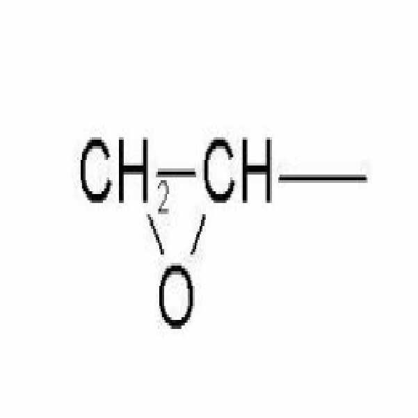
A는 수소원자, 할로겐원자, 티올기, 치환 또는 비치환 아미노기, 치환 또는 치환되지 않은 탄소수 2 내지 15의 헤테로 시클로 알킬기, 치환 또는 비치환된 탄소수 2 내지 20의 알케닐기, 치환 또는 비치환된 탄소수 1 내지 10의 실라닐기, 치환 또는 비치환된 탄소수 6~20의 아릴기를 나타낸다.A is a hydrogen atom, a halogen atom, a thiol group, a substituted or unsubstituted amino group, a substituted or unsubstituted heterocycloalkyl group having 2 to 15 carbon atoms, a substituted or unsubstituted alkenyl group having 2 to 20 carbon atoms, a substituted or unsubstituted carbon number The silanyl group of 1-10, a substituted or unsubstituted C6-C20 aryl group is shown.
본 발명의 일 실시예에 의하면, 상기 화학식 I의 화합물로서는 하기 화학식 II의 화합물이 바람직하다.According to one embodiment of the present invention, the compound of formula II is preferable as the compound of formula I.
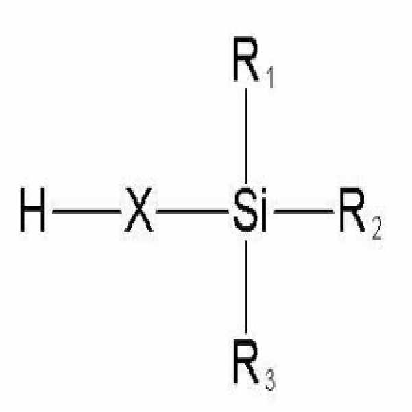
(식중, R1, R2, R3 및 X는 상기 정의한 바와 같다)Wherein R 1 , R 2 , R 3 and X are as defined above.
본 발명의 또 다른 실시예에 따르면, 상기 화학식 I의 화합물로서는 하기 화학식 III의 화합물이 바람직하다.According to another embodiment of the present invention, the compound of formula III is preferable as the compound of formula I.

식중, R1, R2, R3 는 상기 정의한 바와 같으며, R4, R5 및 R6는 각각 독립적으로 수소원자, 할로겐원자, 히드록시기, 치환 또는 비치환된 아민기, -SH, 치환 또는 비치환된 탄소수 1 내지 20의 알킬기, 치환 또는 비치환된 탄소수 3~20의 시클로 알킬기, 치환 또는 비치환된 탄소수 1 내지 20의 알케닐기, 치환 또는 비치환된 탄소수 1 내지 20의 알콕시기, 치환 또는 비치환된 탄소수 6 내지 30의 아릴기, 치환 또는 비치환된 탄소수 6 내지 30의 아릴옥시기, 치환 또는 비치환된 탄소수 1 내지 20의 알킬카르보닐기를 나타내며,Wherein R 1 , R 2 , R 3 are as defined above, and R 4 , R 5 and R 6 are each independently a hydrogen atom, a halogen atom, a hydroxy group, a substituted or unsubstituted amine group, -SH, substituted or Unsubstituted C1-C20 alkyl group, substituted or unsubstituted C3-C20 cycloalkyl group, substituted or unsubstituted C1-C20 alkenyl group, substituted or unsubstituted C1-C20 alkoxy group, substituted Or an unsubstituted aryl group having 6 to 30 carbon atoms, a substituted or unsubstituted aryloxy group having 6 to 30 carbon atoms, a substituted or unsubstituted alkyl carbonyl group having 1 to 20 carbon atoms,
X1는 -O-, -NH-, 치환 또는 비치환된 탄소수 1 내지 20의 알킬렌기, 치환 또는 비치환된 탄소수 2 내지 20의 알케닐렌기, 치환 또는 비치환된 탄소수 6 내지 30의 아릴렌기이다. X 1 is —O—, —NH—, a substituted or unsubstituted alkylene group having 1 to 20 carbon atoms, a substituted or unsubstituted alkenylene group having 2 to 20 carbon atoms, a substituted or unsubstituted arylene group having 6 to 30 carbon atoms to be.
본 발명의 또 다른 실시예에 따르면, 상기 화학식 I의 화합물로서는 하기 화학식 IV의 화합물이 바람직하다.According to another embodiment of the present invention, the compound of formula IV is preferable as the compound of formula I.

식중, R1 내지 R6 은 상기 정의한 바와 같다.In the formula, R 1 To R 6 are as defined above.
본 발명의 또 다른 실시예에 따르면, 상기 화학식 I의 화합물로서는 하기 화학식 V의 화합물이 바람직하다.According to another embodiment of the present invention, the compound of formula (V) is preferred as the compound of formula (I).

식중, R1 내지 R6 은 상기 정의한 바와 같으며, R7 및 R8은 각각 독립적으로 수소원자, 할로겐원자, 히드록시기, 치환 또는 비치환된 아민기, 치환 또는 비치환된 티올기, 치환 또는 비치환된 탄소수 1 내지 20의 알킬기, 치환 또는 비치환된 탄소수 3~20의 시클로 알킬기, 치환 또는 비치환된 탄소수 1 내지 20의 알케닐기, 치환 또는 비치환된 탄소수 1 내지 20의 알콕시기, 치환 또는 비치환된 탄소수 6 내지 30의 아릴기, 치환 또는 비치환된 탄소수 6 내지 30의 아릴옥시기, 치환 또는 비치환된 탄소수 1 내지 20의 알킬카르보닐기를 나타낸다.Wherein R 1 to R 6 are as defined above, and R 7 and R 8 are each independently a hydrogen atom, a halogen atom, a hydroxy group, a substituted or unsubstituted amine group, a substituted or unsubstituted thiol group, a substituted or unsubstituted A substituted C1-C20 alkyl group, a substituted or unsubstituted C3-C20 cycloalkyl group, a substituted or unsubstituted C1-C20 alkenyl group, a substituted or unsubstituted C1-C20 alkoxy group, substituted or An unsubstituted aryl group having 6 to 30 carbon atoms, a substituted or unsubstituted aryloxy group having 6 to 30 carbon atoms, and a substituted or unsubstituted alkyl carbonyl group having 1 to 20 carbon atoms.
본 발명의 또 다른 실시예에 따르면, 상기 화학식 I의 화합물로서는 하기 화학식 VI의 화합물이 바람직하다.According to another embodiment of the present invention, the compound of formula VI is preferable as the compound of formula I.

식중, R1, R2 및 R3은 상기 정의한 바와 같으며, R9 및 R10은 각각 독립적으로 수소원자, 할로겐원자, 히드록시기, 치환 또는 비치환된 아민기, 치환 또는 비치환된 티올기, 치환 또는 비치환된 탄소수 1 내지 20의 알킬기, 치환 또는 비치환된 탄소수 3~20의 시클로 알킬기, 치환 또는 비치환된 탄소수 1 내지 20의 알케닐기, 치환 또는 비치환된 탄소수 1 내지 20의 알콕시기, 치환 또는 비치환된 탄소수 6 내지 30의 아릴기, 치환 또는 비치환된 탄소수 6 내지 30의 아릴옥시기, 치환 또는 비치환된 탄소수 1 내지 20의 알킬카르보닐기를 나타내며,Wherein R 1 , R 2 and R 3 are as defined above, R 9 and R 10 are each independently a hydrogen atom, a halogen atom, a hydroxy group, a substituted or unsubstituted amine group, a substituted or unsubstituted thiol group, Substituted or unsubstituted C1-C20 alkyl group, substituted or unsubstituted C3-C20 cycloalkyl group, substituted or unsubstituted C1-C20 alkenyl group, substituted or unsubstituted C1-C20 alkoxy group , A substituted or unsubstituted aryl group having 6 to 30 carbon atoms, a substituted or unsubstituted aryloxy group having 6 to 30 carbon atoms, a substituted or unsubstituted alkyl carbonyl group having 1 to 20 carbon atoms,
X2는 치환 또는 비치환된 탄소수 1 내지 20의 알킬렌기, 치환 또는 비치환된 탄소수 2 내지 20의 알케닐렌기, 치환 또는 비치환된 탄소수 6 내지 30의 아릴렌기이다. X 2 is a substituted or unsubstituted alkylene group having 1 to 20 carbon atoms, a substituted or unsubstituted alkenylene group having 2 to 20 carbon atoms, a substituted or unsubstituted arylene group having 6 to 30 carbon atoms.
이하 본 발명을 더욱 상세히 설명한다.Hereinafter, the present invention will be described in more detail.
상기 본 발명의 화합물에서 사용되는 치환기인 알킬기는 탄소수 1 내지 20 갖는 직선 또는 가지 단가 알킬기들을 포함하며, 바람직하게는 1 내지 15의 탄소원자를 갖는 직선 또는 가지 단가 알킬기를 포함한다. 상기 용어는 메틸, 에틸, n-프로필, 이소프로필, n-부틸, 이소부틸, tert-부틸, n-헥실, n-옥틸, n-노닐, n-도데실, 트리데실, 펜타데실, n-펜틸 및 이들의 직선 또는 사슬형 유사물과 같은 작용기들에 의해 예시된다. 더욱 바람직한 알킬기는 1 내지 6의 탄소원자를 갖는 저급 알킬기이며, 더욱 더 바람직한 알킬기는 1 내지 3의 탄소원자를 갖는 저급 알킬기이다. The alkyl group, which is a substituent used in the compound of the present invention, includes straight or branched monovalent alkyl groups having 1 to 20 carbon atoms, and preferably includes straight or branched monovalent alkyl groups having 1 to 15 carbon atoms. The term is methyl, ethyl, n-propyl, isopropyl, n-butyl, isobutyl, tert-butyl, n-hexyl, n-octyl, n-nonyl, n-dodecyl, tridecyl, pentadecyl, n- Illustrated by functional groups such as pentyl and their straight or chained analogs. More preferred alkyl groups are lower alkyl groups having 1 to 6 carbon atoms, and even more preferred alkyl groups are lower alkyl groups having 1 to 3 carbon atoms.
여기서 알케닐기는 탄소-탄소 이중결합을 함유하는 탄소수 2 내지 30의 직선형 또는 가지형의 지방족 탄화수소기를 나타낸다. 바람직한 알케닐기는 사슬에 2 내지 15의 탄소원자를 가지며, 더욱 바람직하게는 사슬에 2 내지 6의 탄소원자를 갖는다. 가지형은 하나 이상의 저급 알킬 또는 저급 알케닐기가 알케닐 사슬에 부착된 것을 말한다. 이러한 알케닐기는 치환되지 않거나, 할로겐 원자, 카르복시, 히드록시, 포밀 등을 포함하는 하나 이상의 치환기에 의해 독립적으로 치환될 수 있다. 이들의 예로서 에테닐, n-2-프로페닐, 카르복시에테닐, 카르복시프로페닐 등이 있다.Alkenyl group represents a C2-C30 linear or branched aliphatic hydrocarbon group containing a carbon-carbon double bond here. Preferred alkenyl groups have 2 to 15 carbon atoms in the chain, more preferably 2 to 6 carbon atoms in the chain. Branched refers to one or more lower alkyl or lower alkenyl groups attached to an alkenyl chain. Such alkenyl groups may be unsubstituted or may be independently substituted by one or more substituents including halogen atoms, carboxy, hydroxy, formyl and the like. Examples thereof include ethenyl, n-2-propenyl, carboxyethenyl, carboxypropenyl and the like.
여기서 알콕시기는 -O-R기를 나타내며, 여기서 R은 "C1-C12-알킬", 또는 "아릴", 또는 "헤테로아릴", 또는 "C1-C12-알킬 아릴" 또는 "C1-C12-알킬 헤테로아릴"을 포함한다. 바람직한 알콕시기는 1 내지 6의 탄소원자를 갖는 저급 알콕시기이며, 더욱 바람직한 것으로는 탄소수 1 내지 3의 저급 알콕시기 이다. 예를 들면 메톡시, 에톡시, 프로폭시, 부톡시 및 t-부톡시를 포함한다. 상기 알콕시기는 플루오로, 클로로 또는 브로모와 같은 하나 이상의 할로 원자로 더 치환되어 할로알콕시기를 제공할 수 있다. 1 내지 3개의 탄소원자를 갖는 저급 할로알콕시기가 더욱 바람직하다. 예로서, 플루오로메톡시, 클로로메톡시, 트리플루오로메톡시, 트리플루오로에톡시, 플루오로에톡시 등을 포함한다.Wherein the alkoxy group represents an —OR group, wherein R is “C 1 -C 12 -alkyl”, or “aryl”, or “heteroaryl”, or “C 1 -C 12 -alkyl aryl” or “C 1 -C 12 -Alkyl heteroaryl ". Preferred alkoxy groups are lower alkoxy groups having 1 to 6 carbon atoms, more preferably lower alkoxy groups having 1 to 3 carbon atoms. For example methoxy, ethoxy, propoxy, butoxy and t-butoxy. The alkoxy group may be further substituted with one or more halo atoms such as fluoro, chloro or bromo to provide a haloalkoxy group. More preferred are lower haloalkoxy groups having from 1 to 3 carbon atoms. Examples include fluoromethoxy, chloromethoxy, trifluoromethoxy, trifluoroethoxy, fluoroethoxy and the like.
여기서 아릴기는 단일 고리(single ring)(예를 들면 페닐) 또는 다중 축합 고리(condensed ring)(예를 들면 나프틸)를 갖는 탄소수 6 내지 20의 불포화, 방향족 탄소고리기를 나타낸다. 상기 아릴기는 히드록시, 할로, 할로알킬, 니트로, 시아노, 알콕시 및 저급 알킬아미노와 같은 치환기를 1 내지 3개 가질 수 있다. 아릴 기는 페닐, 나프틸, 테트라히드로나프틸, 인단 및 비페닐과 같은 방향족 라디칼을 포함하며, 바람직한 아릴은 탄소수 6 내지 9의 방향족 라디칼이며, 예로는 페닐 및 이와 유사한 것을 포함한다.The aryl group here represents an unsaturated, aromatic carbocyclic group having 6 to 20 carbon atoms having a single ring (for example phenyl) or multiple condensed ring (for example naphthyl). The aryl group may have 1 to 3 substituents such as hydroxy, halo, haloalkyl, nitro, cyano, alkoxy and lower alkylamino. Aryl groups include aromatic radicals such as phenyl, naphthyl, tetrahydronaphthyl, indane and biphenyl, preferred aryls are aromatic radicals having 6 to 9 carbon atoms, examples include phenyl and the like.
여기서 아릴옥시기는 아릴-O-를 의미하며, 아릴옥시기중 아릴에 대한 정의는 상기한 바와 같다.Herein, the aryloxy group means aryl-O-, and the definition of aryl in the aryloxy group is as described above.
여기서 알킬카르보닐기는 -COOR기를 나타내며, 여기서 R은 "C1-C12-알킬", 또는 "아릴", 또는 "헤테로아릴", 또는 "C1-C12-알킬 아릴" 또는 "C1-C12-알킬 헤테로아릴"을 포함한다. 바람직한 카르보닐기는 탄소수 1 내지 3의 저급 알킬카르보닐이며, 예로는 메틸카르보닐, t-부틸카르보닐 및 이와 유사한 것을 포함한다.Wherein the alkylcarbonyl group represents a -COOR group, where R is "C 1 -C 12 -alkyl", or "aryl", or "heteroaryl", or "C 1 -C 12 -alkyl aryl" or "C 1 -C 12 -alkyl heteroaryl ". Preferred carbonyl groups are lower alkylcarbonyls having 1 to 3 carbon atoms, examples include methylcarbonyl, t-butylcarbonyl and the like.
여기서 알킬렌기는 구조식 -CnH2n -(n은 0 내지 20의 정수이다)으로 나타내진다. 상기 알킬렌기는 직선형 또는 가지형이 있으며, 바람직하게는 1 내지 15의 탄소원자를 갖는 직선 또는 가지 단가 알킬렌기를 포함한다. 상기 용어는 메틸렌, 에틸렌, n-프로필렌, 이소프로필렌, n-부틸렌, 이소부틸렌, tert-부틸렌, n-헥실렌, n-옥틸렌, n-노닐렌, n-도데실렌, 트리데실렌, 펜타데실렌, n-펜틸렌 및 이들의 직선 또는 사슬형 유사물과 같은 작용기들에 의해 예시된다. 더욱 바람직한 알킬렌기는 1 내지 6의 탄소수를 갖는 저급 알킬렌기이며, 더욱 더 바람직한 알킬렌기는 1 내지 3의 탄소원자를 갖는 저급 알킬렌기이다. The alkylene group formula -C n H 2n - is represented by (n is an integer from 0 to 20). The alkylene group may be linear or branched, and preferably includes a straight or branched monovalent alkylene group having 1 to 15 carbon atoms. The term is methylene, ethylene, n-propylene, isopropylene, n-butylene, isobutylene, tert-butylene, n-hexylene, n-octylene, n-nonylene, n-dodecylene, tride Illustrated by functional groups such as styrene, pentadecylene, n-pentylene and their straight or chained analogs. More preferred alkylene groups are lower alkylene groups having 1 to 6 carbon atoms, and even more preferred alkylene groups are lower alkylene groups having 1 to 3 carbon atoms.
여기서 알케닐렌기는 구조식 -CnH2n -2- (n은 2 내지 20의 정수임)으로 나타내진다. Wherein the alkenylene group is represented by the formula -C n H 2n -2- where n is an integer from 2 to 20.
여기서 아릴렌기는 방향족 고리를 포함하는 치환기이고 아릴알킬 또는 아릴알케닐기를 포함할 수 있다. 방향족 고리로는 벤젠고리, 나프탈렌고리, 안트라센고리 등이 이용될 수 있다. Wherein the arylene group is a substituent including an aromatic ring and may include an arylalkyl or arylalkenyl group. As the aromatic ring, a benzene ring, naphthalene ring, anthracene ring and the like can be used.
여기서 실라닐렌기는 구조식 -SiR2-으로 1~6 원자, 바람직하게는 1~4의 원자, 특히 바람직하게는 1~3의 원자를 포함하며, 적어도 하나 이상의 실리콘 원자를 함유하는 치환기이며, 치환기의 원자들은 0~2개의 산소원자, 0~2개의 질소원자, 0~4개의 탄소원자를 함유할 수 있다. 실리콘 및 탄소 원자들은 비치환되거나 또는 같거나 다른 1 내지 2의 할로겐, 알킬 실라닐 또는 실라알킬기로 치환될 수도 있다. 예로는 디알킬실라닐렌[-R2Si-], 디알킬실라자닐렌[-R2SiNH-], 펩티딜실라닐렌[-CO-NH-SiR2-], 트리할로알킬옥시실라닐렌[-CX3R-O-SiR2-], 테트라알킬디실라닐렌[-SiR2-SiR2-], 및 디알킬실록시(디알킬)실라닐렌[-R2SiO2-SiR2-]이 포함된다.Wherein the silanylene group is a substituent containing 1 to 6 atoms, preferably 1 to 4 atoms, particularly preferably 1 to 3 atoms, and containing at least one silicon atom in the formula -SiR 2- ; Atoms can contain 0-2 oxygen atoms, 0-2 nitrogen atoms, and 0-4 carbon atoms. Silicon and carbon atoms may be unsubstituted or substituted with the same or different halogen, alkyl silanyl or silaalkyl groups. Examples include dialkylsilanylene [-R 2 Si-], dialkylsilazanilene [-R 2 SiNH-], peptidylsilanylene [-CO-NH-SiR 2- ], trihaloalkyloxysilanylene [ -CX 3 RO-SiR 2- ], tetraalkyldisylanylene [-SiR 2 -SiR 2- ], and dialkylsiloxy (dialkyl) silanylene [-R 2 SiO 2 -SiR 2- ]. .
여기서 헤테로알킬렌기는 N, O, 또는 S 중에서 선택된 1 내지 3의 헤테로 원자를 포함하고 나머지 원자가 C인 탄소수 1~20의 직선 또는 가지형의 알킬렌을 의미하며, 바람직하게는 탄소수 1~15의 저급 헤테로알킬렌, 더욱 바람직하게는 1~6의 저급 헤테로알킬렌이다. 예로서, 에틸아미노프로필렌, 아미노프로필렌등을 포함한다.Here, the heteroalkylene group means a straight or branched alkylene having 1 to 3 carbon atoms containing 1 to 3 hetero atoms selected from N, O, or S, and the remaining atoms are C, preferably 1 to 15 carbon atoms. Lower heteroalkylene, more preferably 1-6 lower heteroalkylene. Examples include ethylaminopropylene, aminopropylene and the like.
여기서, 헤테로 시클로 알킬기 N, O, 또는 S 중에서 선택된 1 내지 3의 헤테로 원자를 포함하고, 나머지 고리원자가 C인 고리 원자수 3 내지 10의 모노 사이클릭 또는 비사이클릭 알킬을 의미하며, 바람직하게는 탄소 원자수 1~6의 저급 헤테 로시클로알킬이 바람직하다. 예로서, 옥시 시클로프로필, 옥시 시클로부틸등을 포함한다. Here, it means a monocyclic or bicyclic alkyl having 3 to 10 ring atoms containing 1 to 3 heteroatoms selected from a heterocyclo alkyl group N, O, or S, and the remaining ring atoms are C. Lower heterocycloalkyl having 1 to 6 carbon atoms is preferred. Examples include oxy cyclopropyl, oxy cyclobutyl and the like.
본 발명에 의한 일 실시예에 따르면 Si 함유 물질은 하기 표1의 화합물을 포함한다. According to an embodiment of the present invention, the Si-containing material includes the compound of Table 1 below.
표 1Table 1

![]()
![]()

그 중 본 발명에 의한 일 실시예에 따르면 Si 함유 물질로는 HMDS(hexamethyl disilazane)이 바람직하다. According to one embodiment of the present invention, the Si-containing material is preferably hexamethyl disilazane (HMDS).
본 발명에 의한 일 실시예에 따르면 상기 Si 함유 물질 코팅층의 두께는 0.005㎛~1㎛, 바람직하게는 0.01㎛~0.05㎛, 더욱 바람직하게는 0.02㎛~0.03㎛이 바람직하다.According to an embodiment of the present invention, the Si-containing material coating layer has a thickness of 0.005 μm to 1 μm, preferably 0.01 μm to 0.05 μm, and more preferably 0.02 μm to 0.03 μm.
이하, 첨부된 도면을 참조하여 본 발명의 실시예에 따른 전극 및 리튬전지에 대하여 더욱 상세히 설명한다.Hereinafter, an electrode and a lithium battery according to an exemplary embodiment of the present invention will be described in detail with reference to the accompanying drawings.
도 1은 본 발명에 따른 리튬전지를 구비하는 전극 조립체의 사시도를 나타낸다. 도 2a~2c는 본 발명이 실시예에 따른 전극의 단면도를 나타낸다. 도 3은 통상의 전극의 부분 확대 단면도이다. 도 4는 본 발명에 따른 전극 표면의 반응설명도이다. 1 is a perspective view of an electrode assembly having a lithium battery according to the present invention. 2A to 2C show cross-sectional views of electrodes according to an embodiment of the present invention. 3 is a partially enlarged cross-sectional view of a conventional electrode. 4 is an explanatory view of the reaction of the electrode surface according to the present invention.
본 발명의 일 실시예에 따른 전극을 채용한 리튬전지의 전극 조립체(100)는 양극집전체의 소정영역에 양극활물질층이 형성된 양극전극판(110), 음극집전체의 소정 영역에 음극활물질층이 형성된 음극전극판(120)이 젤리-롤 형상으로 권취되어 형성되거나, 상기 양극전극판(110), 상기 음극전극판(120), 상기 양극전극판(110) 및 음극 전극판(120) 상이에 위치하여 상기 양극전극판(110)과 음극전극판(120)의 쇼트를 방지하고, 리튬 이온의 이동만 가능하게 하는 세퍼레이터(130, 140)가 젤리-롤 형상으로 권취되어 형성된다. The
이때 양극전극판(110) 및 음극전극판(120)중 전극집전체의 적어도 한 면에 다공막층이 도포되어, 과충전, 고온에서 안정한 이차전지를 제공한다. 이때, 서로 대향하게 될 상기 두 전극의 전극면들 가운데 적어도 한 쪽에 다공막이 존재하도록 하려면, 가령, 두 전극을 적층하고, 권취하여 이루어지는 젤리롤 형 전극 조립체에서는, 두 전극 각각의 바깥쪽 면에 다공막을 형성한다. 혹은, 두 전극 각각의 내측 면에 다공막을 형성하거나, 두 전극 중 한 전극의 내측 면 및 바깥측 면 모두에 다공막을 형성할 수도 있다. In this case, the porous membrane layer is coated on at least one surface of the electrode collector of the
이때, 다공막은 별도의 필름으로 형성되지 않고, 전극의 활물질 슬러리가 덮인 표면들 가운데 적어도 한 면에 다공막액 혹은 다공막의 전구체 액을 도포한 뒤 다공막액에서 용제 성분을 제거하거나, 전구체를 큐어링하는 방법으로 형성된다. 바인더와 용매로 이루어진 액상 물질에 2차 입자를 고르게 분산시킨 다공막액에 전극을 담그는 방법을 사용할 경우, 그 전극의 내측 면 및 바깥쪽 면과 상하의 좁은 면에도 다공막이 덮이게 된다. 그러므로, 다공막으로 덮인 전극과 다른 전극과의 단락이 보다 효과적으로 방지될 수 있다.In this case, the porous membrane is not formed as a separate film, and after coating the porous membrane liquid or the precursor liquid of the porous membrane on at least one of the surfaces covered with the active material slurry of the electrode, the solvent component is removed from the porous membrane liquid, or the precursor It is formed by the method of curing. When the electrode is immersed in a porous membrane liquid in which secondary particles are evenly dispersed in a liquid substance composed of a binder and a solvent, the porous membrane is also covered on the inner and outer surfaces of the electrode and a narrow upper and lower sides thereof. Therefore, a short circuit between the electrode covered with the porous membrane and another electrode can be prevented more effectively.
이때, 다공막액 형성을 위해 먼저 바인더 물질, 용매, 세라믹 분말이 액상의 혼합물을 이룬다. 다공막액 형성을 위해 이들 2차 입자로 이루어진 분말을 바인더 및 용매와 섞는다. 바인더의 이온전도도에 관계없이 다공막의 이온전도도를 높이기 위해서는, 바인더는 다공막 형성용 슬러리 내에 소량 사용되는 것이 바람직하다. 본 발명의 다공막에서 세라믹 물질과 바인더의 비율은 질량 기준으로 98:2 내지 85:15이 바람직하다. 이로서, 바인더가 필러 물질을 덮어 필러 물질 내로 이온 전도가 제한되는 문제를 피할 수 있다. 바인더의 양을 줄이기 위해서는 바인더를 고르게 분산시킬 필요가 있으며, 본 발명에 따라 일부 소결한 세라믹 재료를 필러로 이용하고, 아크릴 고무계 바인더를 사용하면, 바인더의 분산이 용이하여 소량의 바인더로 큰 공극율을 가진 막을 얻을 수 있다. In this case, first, a binder material, a solvent, and a ceramic powder form a liquid mixture to form a porous membrane liquid. The powder composed of these secondary particles is mixed with a binder and a solvent to form a porous membrane solution. Regardless of the ion conductivity of the binder, in order to increase the ion conductivity of the porous membrane, the binder is preferably used in a small amount in the slurry for forming the porous membrane. In the porous membrane of the present invention, the ratio of the ceramic material and the binder is preferably 98: 2 to 85:15 by mass. This avoids the problem that the binder covers the filler material and the ion conduction into the filler material is limited. In order to reduce the amount of binder, it is necessary to disperse the binder evenly, and when using a sintered ceramic material as a filler according to the present invention and using an acrylic rubber binder, it is easy to disperse the binder so that a large amount of voids can be obtained with a small amount of binder. You can get a membrane.
이런 상태의 혼합물을 정해진 전극면에 도포한다. 혼합물 도포는 전극면에 대해 전면 인쇄의 방법, 스프레이 방법으로 이루어질 수 있다. 본 발명의 일 실시예에서는 전극판을 액상의 혼합물에 담그고, 그라비아(gravure) 롤러로 막두께를 제어한 후, 베이킹 하는 방법으로 다공막을 형성할 수 있으며, 또 다른 실시예에서는 전극 표면상에 딥 방법으로 혼합액을 코팅하고, 120℃의 건조기에 전극을 통과시켜 용매를 제거하고, 전극 면에 다공막을 얻는 등, 기타 다양한 방법을 사용할 수 있다. The mixture in this state is applied to a predetermined electrode surface. Application of the mixture may be carried out by the method of front printing or spraying on the electrode surface. In one embodiment of the present invention, the electrode plate is immersed in a liquid mixture, the film thickness is controlled by a gravure roller, and then a porous film is formed by baking, and in another embodiment, a dip is formed on the electrode surface. Various methods can be used, such as coating a mixed liquid by a method, passing an electrode through a 120 degreeC dryer, removing a solvent, and obtaining a porous film on an electrode surface.
본 발명의 다공막의 두께는 1.5 내지 30 ㎛ 정도로 이루어질 수 있다.The thickness of the porous membrane of the present invention may be made about 1.5 to 30 ㎛.
본 발명에 의한 일 실시예에 따르면 상기 다공막 층은 밴드 갭을 가지는 세라믹 필러의 1차 입자가 부분 소결 또는 재결정 결합한 2차 입자를 바인더로 결합하여 이루어지는 다공막을 가지는 것을 특징으로 한다. 본 발명에서 다공막의 2차 입자는 방상(포도송이 모양) 혹은 층상의 입자군인 것이 바람직하다. 또한, 본 발명에서 1차 입자 자체가 방상 입자군이나 비늘형 입자가 적층상으로 결속된 층상 입자군일 수도 있다. 이때, 응집된 2차 입자를 만드는 방법은, 다양한 화학적, 물리적 방법 등을 사용할 수 있으며, 그 가운데 용이한 방법의 하나로는 입자 재질의 용융 온도 부근까지 가열을 통해 재질의 온도를 상승시키고, 넥킹(necking)시키는 방법을 들 수 있다. 입자들을 일부 용융 혹은 일부 소결시켜 응집시키는 가공을 할 때의 세라믹 재료를 얼마나 용융시킬 것인가는 이후 세라믹 재료에 바인더 및 용매 를 섞어 페이스트(paste)나 분산상의 다공막액을 만들 때의 재료 교반 과정에서 본 발명의 특징적 입자 형상이 일정 정도로 유지될 수 있고, 형성된 다공막의 밀도가 낮도록 결정되는 것이 바람직하다. According to an embodiment of the present invention, the porous membrane layer is characterized by having a porous membrane formed by combining secondary particles, in which primary particles of a ceramic filler having a band gap are partially sintered or recrystallized, with a binder. In the present invention, the secondary particles of the porous membrane are preferably in the form of a staple (grape-shaped) or layered particle group. Further, in the present invention, the primary particles themselves may be a layered particle group or a layered particle group in which scale particles are bound in a stack. At this time, a method of making agglomerated secondary particles may use a variety of chemical and physical methods, and one of the easy methods among them is to raise the temperature of the material by heating to near the melting temperature of the particle material, necking ( necking). How much of the ceramic material is melted when the particles are partially melted or partially sintered to be agglomerated is determined in the process of stirring the material when a binder or a solvent is mixed with the ceramic material to form a paste or dispersed porous membrane solution. It is preferable that the characteristic particle shape of the present invention can be maintained to a certain degree and determined so that the density of the formed porous membrane is low.
본 발명에서 바인더는 주로 고분자 수지로 이루어지며, 고분자 수지로는 200℃ 이상의 열에도 견딜 수 있는 아크릴레이트나 메타크릴레이트의 중합체 또는 이들의 공중합체로 이루어지는 것이 바람직하다.In the present invention, the binder is mainly composed of a polymer resin, and the polymer resin is preferably made of a polymer of acrylate or methacrylate or a copolymer thereof that can withstand heat of 200 ° C. or higher.
본 발명에서 세라믹 재질로는 지르코늄 산화물(가령 ZrO2), 알루미나(Al2O3) 실리카(SiO2), 티타늄 산화물(TiO2), 이온 전도성 유리 등의 각각과 이들의 혼합물을 사용할 수 있으며, 특히 지르코늄 산화물을 사용하는 것이 바람직하다. 기타, 다공막을 이루는 세라믹 재질로는 지르코늄, 알미늄, 실리콘, 티타늄 각각의 절연성 질화물, 수산화물, 케톤화물, 혹은 이러한 화합물들의 혼합물이 사용될 수 있다. 여기서, 티타늄 나이드라이드(TiN) 등은 도전성을 가지므로 본 발명의 세라믹 재질로 적합하지 않기 때문에 절연성 질화물로 한정한다. 이들을 많이 사용한 다공막은 국부적으로 300℃ 정도의 고온에도 수축 변형이나 용융 같은 전극간 단락을 유발하는 변형을 방지하는 역할을 한다. 또한, 이들 재료는 전체적으로 세퍼레이터막의 보존 유지성을 향상시키고, 일부 소결된 방상 구조는 공공율 혹은 공극율을 높일 수 있다는 장점이 있다.In the present invention, as the ceramic material, each of zirconium oxide (eg, ZrO 2 ), alumina (Al 2 O 3 ) silica (SiO 2 ), titanium oxide (TiO 2 ), ion conductive glass, and mixtures thereof may be used. In particular, it is preferable to use zirconium oxide. In addition, as a ceramic material constituting the porous film, an insulating nitride, a hydroxide, a ketone, or a mixture of these compounds may be used, respectively, for zirconium, aluminum, silicon, and titanium. Herein, titanium nitride (TiN) and the like are conductive and are not suitable for the ceramic material of the present invention, so they are limited to insulating nitride. Porous membranes using many of them serve to prevent deformation that causes short-circuit between electrodes such as shrinkage deformation and melting even at a high temperature of about 300 ° C. In addition, these materials have the advantage of improving the preservation and retention of the separator film as a whole, and partly sintered rectangular structure can increase the porosity or the porosity.
이들 세라믹 재료를 이용할 때 본 발명의 방상의 입자군 혹은 2차 입자를 이 루는 개별 입자는 0.01 내지 0.3㎛ 이고, 층상의 입자군을 형성하는 비늘 모양의 개별 박편은 너비가 100nm 내지 1㎛ 인 것이 바람직하다. 이러한 입자 크기는 양호한 특성을 내는 재료를 형성한 뒤 주사전자 현미경(SEM) 사진을 관찰하여 확인할 수 있다. 본 발명에서 다공막 층을 구성하는 세라믹 재료는 200℃ 온도에서 열팽창율이 0.2% 이내, 400℃ 온도에서 열팽창율이 0.1 내지 0.4%인 것이 바람직하다. 이러한 열팽창율보다 높은 열팽창율을 가진 세라믹 재료는 전지 내부의 압력 증가로 인해 전지 자체의 형상을 변형시키는 문제가 있다. When using these ceramic materials, the individual particle which forms the particle group or secondary particle of this invention is 0.01-0.3 micrometer, and the scale-shaped individual flake which forms a layered particle group has a width of 100 nm-1 micrometer. It is preferable. This particle size can be confirmed by observing a scanning electron microscope (SEM) photograph after forming a material having good properties. In the present invention, the ceramic material constituting the porous membrane layer preferably has a coefficient of thermal expansion of 0.2% or less at 200 ° C and 0.1 to 0.4% of thermal expansion at 400 ° C. Ceramic materials having a thermal expansion rate higher than the thermal expansion rate have a problem of deforming the shape of the battery itself due to an increase in pressure inside the battery.
본 발명에서 세라믹 재료와 고분자 수지로 이루어진 다공막은 공공율이 50% 이상으로 형성되는 것이 바람직하다. 이때, 공공율은 대상 물체를 절단한 전체 단면에서 빈 공간에 해당하는 면적이 차지하는 비율로서, 부피 기준의 공극율과 함께 대상 물질에서 다공성의 정도를 나타낸다. 공공율은 재료의 절단면에 대한 전자현미경(SEM) 사진을 통해 판단될 수 있다. In the present invention, the porous film made of a ceramic material and a polymer resin is preferably formed with a porosity of 50% or more. In this case, the porosity is the ratio occupied by the area corresponding to the empty space in the entire cross section of the cut object, and indicates the degree of porosity in the target material together with the porosity based on the volume. Porosity can be determined by electron microscopy (SEM) photography of the cut surface of the material.
이렇게 형성된 다공막은 세라믹 재료 자체의 미다공성, 방상 구조를 형성하는 입자군의 개개의 1차 입자 사이의 공극, 바인더에 의해서 결합된 방상 입자군들 사이의 공극, 모두가 다공막의 공공율을 높이는 데 기여하며, 결과적으로, 이들 공극 모두가 다공막 내에서의 전해액 투과성, 리튬 이온 이동도를 높이는 데 기여하게 된다. The porous membrane thus formed has the microporosity of the ceramic material itself, the voids between the individual primary particles of the particle group forming the spherical structure, the voids between the group of the spherical particle groups bound by the binder, and the porosity of the porous membrane. As a result, all of these pores contribute to increasing electrolyte permeability and lithium ion mobility in the porous membrane.
도 2a~2c는 본 발명의 일 실시예에 따른 전극의 단면도이다.2A to 2C are cross-sectional views of electrodes according to an embodiment of the present invention.
도 2a~2c에 따라, 다공막 자체가 세퍼레이터의 역할을 할 수 있으므로 두 전 극 사이에 별도의 세퍼레이터를 설치하는 것은 생략될 수 있다. 이 경우, 세퍼레이터의 셧 다운(shot down)을 통한 전류 차단의 역할을 할 수 없게 된다. 그러나, 과충전시나 기타 온도 상승이 있을 때 다공성 막층과 전극 사이의 밀착성이 좋지 않은 부분에서 발생하는 리튬 석출로부터 생기는 미소 단락, 세라믹 재료와 리튬 포함 물질 사이에 고온시 발생하는 p/n 반도체 기능에 의해 이온의 이동이 억제된다. 이런 작용에 의해 셧 다운에 대응되는 전류 차단 역할이 이루어지고, 안전성 확보가 가능하게 된다.According to FIGS. 2A to 2C, since the porous membrane itself may serve as a separator, installing a separate separator between two electrodes may be omitted. In this case, it becomes impossible to act as a current interruption through the shot down of the separator. However, due to micro short circuits resulting from lithium precipitation, which occurs in areas of poor adhesion between the porous membrane layer and the electrode during overcharging or other temperature rises, and due to the p / n semiconductor function occurring at high temperatures between ceramic materials and lithium-containing materials. Movement of ions is suppressed. This action serves to cut off the current corresponding to the shutdown, ensuring safety.
또는, 권취된 상태의 두 전극 사이에는 종래의 리튬 전지와 같이 별도의 폴리올레핀계 수지로 이루어진 절연막이 존재할 수 있다. 이런 경우, 다공막과 이들 폴리올레핀계 수지 절연막이 함께 전지 내에서 세퍼레이터로 작용하게 된다. Alternatively, an insulating film made of a separate polyolefin resin may exist between two electrodes in a wound state, as in a conventional lithium battery. In this case, the porous membrane and these polyolefin resin insulating films together act as separators in the battery.
도 2a~2d에 따라, 전극 표면에 세퍼레이터 기능을 갖는 다공막을 형성하는 방법은 전극과 별도의 세퍼레이터를 형성하는 통상의 방법에 비해 몇 가지 유리한 점을 가진다. According to Figs. 2A to 2D, the method of forming a porous film having a separator function on the electrode surface has several advantages over the conventional method of forming a separator separate from the electrode.
즉, 종래와 같이 세퍼레이터가 별도로 형성될 경우, 두 전극과 세퍼레이터를 적층하거나 적층 후 와형으로 권취하여 전극 조립체를 형성할 때 세퍼레이터의 정렬이 어긋나서 두 전극 사이에 단락이 이루어지는 문제가 발생될 수 있다. 그러나, 세퍼레이터가 전극 표면을 커버하도록 전극과 함께 형성되면 세퍼레이터를 전극 사이에 끼워 정렬할 필요가 없어지고, 정렬 불량에 따른 문제도 없어진다. That is, when the separator is formed separately as in the related art, when the two electrodes and the separator are laminated or wound up after lamination to form an electrode assembly, the separator may be misaligned and a short circuit may occur between the two electrodes. . However, when the separator is formed with the electrode to cover the electrode surface, there is no need to sandwich the separator between the electrodes, and the problem due to misalignment is also eliminated.
그리고, 세퍼레이터가 전극과 별도로 형성된 경우는 전지가 과열될 때 전지 내의 세퍼레이터가 수축 작용을 일으키고, 이에 따라 전극 사이의 단락을 일으킬 수 있다. 그러나, 세퍼레이터가 일단 전극과 결착되어 형성되면 전지가 과열되어도 그 결착력에 의해 세퍼레이터가 열을 받아 수축되거나, 단락을 일으키는 확률을 낮출 수 있다. 또한, 별개의 세퍼레이터로 형성하는 경우에 비해 전극에 세퍼레이터 역할을 하는 다공막이 결착되도록 한 본 발명 실시예의 전지에서는 전지 생산 공정 중 세퍼레이터가 찢어지는 등의 손상을 입을 확율을 낮출 수 있다. In the case where the separator is formed separately from the electrode, the separator in the battery may cause a contraction action when the battery is overheated, thereby causing a short circuit between the electrodes. However, once the separator is formed by binding to the electrode, even if the battery is overheated, the binding force can reduce the probability that the separator receives heat and contracts or causes a short circuit. In addition, compared to the case of forming a separate separator, in the battery of the embodiment of the present invention in which the porous membrane serving as the separator is bound to the electrode, the probability of damaging the separator during the battery production process may be lowered.
또한, 저항 길이가 짧을수록 저항이 줄어들듯이 세퍼레이터가 얇을수록 통상적으로 세퍼레이터를 통한 이온전도도가 늘어나고, 전지의 고출력 특성이 좋아진다. 다공막을 전극 표면에 형성하여 전극과 세퍼레이터를 일체로 하는 경우, 세퍼레이터는, 가공을 위해 자체를 지탱할 정도의 기계적 강도를 가질 필요가 없으므로 기계적 강도의 제약 없이 연한 재질로 얇게 형성될 수 있다.In addition, as the resistance length decreases as the resistance length decreases, the thinner the separator, the ion conductivity through the separator typically increases, and the high output characteristics of the battery are improved. When the porous membrane is formed on the surface of the electrode to integrate the electrode and the separator, the separator may be thinly formed with a soft material without restricting the mechanical strength since the separator does not have to have a mechanical strength sufficient to support itself for processing.
본 발명의 일 실시예에 따른 전극(200)은 도 2a를 참조하면, 전극집전체(210), Si 함유 물질층(220), 전극활물질층(230), 다공막층(240)을 포함하여 형성된다. Referring to FIG. 2A, an
도 2a를 참조하면, 본 발명에 따른 일 실시예에서는 전극의 전극집전체 사이에 Si 함유 물질층이 도포되어, 양극활물질층 또는 음극활물질층과 전극집전체 사이의 접착력을 증가시키는 한편, 전극집전체의 산화를 방지하고, 전극활물질의 탈리를 막아준다. 또한 전극활물질을 코팅, 압연한 후 전극활물질층 위에 Si 함유 물질층을 도포함으로써, 전극상의 OH기를 제거시켜 전해액과 전극활물질간의 접촉각을 감소시킴으로써, 전해액의 함습을 증가시켜 전지의 주액성을 향상시킬 수 있게 된다. 또한, 전극 활물질층 위에 다공성 막을 형성하여, 별도의 세퍼레이터 없이도 두 전극 사이의 단락을 방지하는 한편, 별도의 세퍼레이터를 갖는 전지보다 저항이 낮고, 이온 전도도가 증가함에 따른 출력특성이 좋아진다.Referring to FIG. 2A, in one embodiment according to the present invention, a Si-containing material layer is applied between electrode collectors of an electrode to increase adhesion between the cathode active material layer or the anode active material layer and the electrode collector, and It prevents oxidation of the whole and prevents detachment of electrode active material. In addition, after coating and rolling the electrode active material, the Si-containing material layer is coated on the electrode active material layer to remove OH groups on the electrode, thereby reducing the contact angle between the electrolyte and the electrode active material, thereby increasing the moisture content of the electrolyte and improving the liquid-liquidity of the battery. It becomes possible. In addition, a porous membrane is formed on the electrode active material layer to prevent short circuits between the two electrodes even without a separate separator, and has a lower resistance than a battery having a separate separator, thereby improving output characteristics due to an increase in ion conductivity.
본 발명에 따른 전극은 Si 함유 물질층을 포함한다. 따라서, 종래의 전극과 비교할 때, 도 3를 참조하면, 전극집전체(510)와 전극활물질층(530) 사이의 밀착력이 좋지 않아서, 전극활물질과 전극집전체 사이에 접한 부분(접착지점: 520)과 접하지 못한 부분(540)이 발생하여, 전극활물질과 접한 부분의 전기력선은 B와 같이 직선으로 흐를 수 있으나, 접하지 못한 부분은 A와 같이 접착지점으로 전기력선이 갈라져서 흐르게 된다. 따라서, 접착지점에서는 전자밀도가 집중되어 전극집전체의 이온화가 진행된다. 전극집전체의 이온화가 계속되면 금속의 용출반응에 의해 접점부가 파괴됨에 따라 전극활물질과 전극집전체의 밀착성이 떨어짐과 동시에 접착성능도 나빠지게 되며, 또한 이로 인해 수명 용량이 떨어지는 원인이 되었다. 또한 전기력선이 흐르지 않는 부분에서는, 금속 이온이 석출(덴드라이트)된다. 활물질의 구성으로부터 전지 제작 초기에 3.5V를 가지고 있기 때문에 그 시점에서 이 반응이 진행된다. 즉, 전지 조립 후 초기 에이징 시점에서 경시적으로 금속 덴드라이트가 생길 수 있고, 이로 인해 OCV 불량을 일으킬 수 있다. 또한 금속 이온은 이동가능하므로 양극상에서 덴드라이트가 형성될 가능성도 있다. 그러나 본 발명에 따르면, 도 4를 참조하면, 전극집전체에 Si 함유 물질층(본 실시예에서는 HMDS: hexamethyl disilazane)을 도포함으로써, 공기 또는 수분 중의 산소가 전극집전체와 반응하여 금속 박막에 남아있던 OH기와 Si 함유 물질의 Si가 탈수소 반응을 하여 전극집전체 상의 OH기를 제거함과 동시에 Si-O 결합을 형성함으로써, 금속집전체와 전극활물질의 밀착성을 증가시켜 전면적으로 고른 접착이 가능하여 전류가 집중되는 것을 막을 수 있다. 이로 인해, 금속집전체의 산화를 방지하여, 전지 저항의 상승을 막고, 전압상승에 따른 이온화를 방지할 수 있다. 한편, 오믹컨택트를 향상시켜, 쇼트키-배리어를 낮추게 된다. 따라서 음극의 저항은 약 40% 감소, 전지로서는 Si 함유 물질층 미처리 전지 대비 약 20%의 저항 감소 효과가 있다. 또한, 전극집전체와 전극활물질의 밀착성이 향상되어 박리가 없고 강도가 향상되었다. 따라서, 본 발명에 따른 전극을 사용하는 경우 저항의 저하, 수명 특성이 향상된 전지를 제조할 수 있다.The electrode according to the invention comprises a Si containing material layer. Therefore, as compared with the conventional electrode, referring to FIG. 3, the adhesion between the electrode
도 2b는 본 발명의 또 다른 실시예에 따른 전극의 단면도이다. 2B is a cross-sectional view of an electrode according to another embodiment of the present invention.
본 발명에 따른 전극(300)은 전극집전체(310), 전극활물질층(320), Si 함유 물질층(330) 및 다공성막(340)을 포함하여 형성된다.The
상기 Si 함유 물질층(330)은 전극활물질층 위에 형성된다. 도 4를 참고하면, 전극활물질층(320) 위에 Si 함유 물질층(HMDS)을 도포함으로써, 공기 또는 수분 중의 산소가 전극집전체와 반응하여 금속 박막에 남아있던 OH기와 Si 함유 물질의 Si가 탈수소 반응을 하여 전극집전체 상의 OH기를 제거함으로써, 전극활물질과 전해액 사이의 접촉각을 감소시켜 전해액 함습을 증가시켜 주액성을 향상시키게 된다.The Si-containing
도 2c는 본 발명의 또 다른 실시예에 따른 전극의 단면도이다. 본 발명에 따른 전극(400)은 전극집전체(410), Si 함유 물질층(420), 전극 활물질(430), Si 함유 물질층(420), 및 다공성막(440)의 순서로 적층된다. 이로서, 상술한 바와 같이 전극집전체(410)와 전극활물질층(430) 사이의 밀착성이 증가되어, 전극집전체의 산화를 방지하는 한편, 전극활물질의 탈리를 방지하여 수명 특성을 높이고, 전극활물질과 전해액의 접촉각을 감소시킴에 따라 주액성을 향상시키는 한편, 전극활물질과 다공성막 사이의 밀착력을 증가시켜, 이를 채용한 전지는 수명특성이 뛰어나며, 전지 저항이 낮고, 고용량이며, 내단락성 및 내열성 등의 안전성이 뛰어나다.2C is a cross-sectional view of an electrode according to another embodiment of the present invention. The
이때 Si 함유 물질층의 도포는 음극 전극판에 형성하는 것이 비용 대비면에서 효과적이다.In this case, it is effective to form the Si-containing material layer on the cathode electrode plate in terms of cost.
본 발명의 일 실시예에 따르면 상기 Si 함유 물질층은 기상 증착의 방법으로 도포되는 것이 바람직하다.According to an embodiment of the present invention, the Si-containing material layer is preferably applied by vapor deposition.
본 발명에서 상기 전극집전체는 통상의 이차전지에서 사용되는 금속, 예를 들면, 알루미늄 금속 또는 구리 금속으로 이루어질 수 있다. In the present invention, the electrode current collector may be made of a metal, for example, aluminum metal or copper metal, used in a conventional secondary battery.
본 발명에서 상기 전극활물질은 통상의 이차전지에서 사용되는 전극활물질, 예를 들면, 양극활물질로는 LiCoO2, LiMn2O4, LiNiO2, LiMnO2 등의 리튬 산화물이 사 용되며, 음극활물질로는 천연흑연, 인조 흑연 또는 그 혼합물이거나, Si, Sn, 산화주석, 주석합금 복합체(composite tin alloys), 전이 금속 산화물, 리튬 금속 나이트라이드 또는 리튬 금속 산화물 등이 사용된다.In the present invention, the electrode active material is an electrode active material used in a conventional secondary battery, for example, lithium oxide such as LiCoO 2 , LiMn 2 O 4 , LiNiO 2 , LiMnO 2 is used as the cathode active material, Is natural graphite, artificial graphite, or mixtures thereof, or Si, Sn, tin oxide, composite tin alloys, transition metal oxides, lithium metal nitrides or lithium metal oxides, and the like are used.
본 발명에 따라 전극집전체, 전극활물질층, Si 함유 물질층 및 다공막층을 포함한 전극이 적층되어 권취된다. According to the present invention, electrodes including an electrode current collector, an electrode active material layer, a Si-containing material layer, and a porous membrane layer are laminated and wound up.
본 발명에 따른 일 실시예에서의 리튬 전지의 형성방법은, 전극집전체에 바인더용 수지와 전극 활물질을 포함하는 슬러리를 도포하여 전극을 형성하는 단계, 전지 내에서 서로 대향하게 될 상기 두 전극의 전극면들 가운데 적어도 한 쪽에 다공막이 존재하도록 상기 전극면에 상기 다공막을 형성하는 단계, 상기 전극집전체 및/또는 상기 전극활물질 위에 Si 함유 물질층을 형성하는 단계, 상기 전극을 적어도 하나 이상 포함하는 전극조립체를 형성하는 단계를 포함하여 이루어진다.In a method of forming a lithium battery according to an embodiment of the present invention, forming an electrode by applying a slurry including a binder resin and an electrode active material to an electrode current collector, and forming the electrode, the two electrodes to be opposed to each other in the battery. Forming the porous film on the electrode surface such that the porous film exists on at least one of the electrode surfaces, forming a Si-containing material layer on the electrode current collector and / or the electrode active material, and including at least one electrode It comprises a step of forming an electrode assembly.
또한 본 발명에 따른 전극을 채용한 전지는 다음과 같이 제조될 수 있다. In addition, the battery employing the electrode according to the present invention can be manufactured as follows.
먼저, 양극활물질, 도전재, 결합재 및 용매를 혼합하여 양극활물질 조성물을 준비한다. 상기 양극활물질 조성물을 전극집전체에 직접 코팅 및 건조하여 양극판을 준비한다. 상기 양극활물질 조성물을 별도의 지지체상에 캐스팅한 다음, 이 지지체로부터 박리하여 얻은 필름을 전극집전체 상에 라미네이션하여 양극을 제조하는 것도 가능하다. First, a cathode active material composition is prepared by mixing a cathode active material, a conductive material, a binder, and a solvent. The cathode active material composition is directly coated and dried on an electrode current collector to prepare a cathode plate. The cathode active material composition may be cast on a separate support, and then a film obtained by peeling from the support may be laminated on an electrode current collector to prepare a cathode.
상기 양극활물질로는 리튬함유 금속 산화물로서, 당업계에서 통상적으로 사용되는 것이면 모두 사용가능하며, 예컨대, LiCoO2, LiMnxO2x, LiNi1 - XMnxO2X(x=1, 2), Ni1-X-Y CoXMnO2등을 들 수 있으며, 보다 구체적으로는 LiMn2O4, LiCoO2, LiNiO2, LiFeO2, V2O5, TiS 및 MoS 등의 리튬의 산화 환원이 가능한 화합물들이다. The positive electrode active material may be any lithium-containing metal oxide, as long as it is commonly used in the art. For example, LiCoO 2 , LiMn x O 2x , LiNi 1 - X MnxO 2X (x = 1, 2), Ni 1 -XY Co X MnO 2 , and the like, and more specifically, compounds capable of redoxing lithium, such as LiMn 2 O 4 , LiCoO 2 , LiNiO 2 , LiFeO 2 , V 2 O 5 , TiS, and MoS.
도전재로는 카본 블랙을 사용하며, 결합재로는 비닐리덴 플루오라이드/헥사플루오로프로필렌 코폴리머, 폴리비닐리덴플루오라이드, 폴리아크릴로니트릴, 폴리메틸메타크릴레이트, 폴리테트라플루오로에틸렌 및 그 혼합물, 스티렌 부타디엔 고무계 폴리머를 사용하며, 용매로는 N-메틸피롤리돈, 아세톤, 물 등을 사용한다. 이때 양극활물질, 도전재, 결합재 및 용매의 함량은 리튬전지에서 통상적으로 사용하는 수준이다. Carbon black is used as the conductive material, and vinylidene fluoride / hexafluoropropylene copolymer, polyvinylidene fluoride, polyacrylonitrile, polymethyl methacrylate, polytetrafluoroethylene and mixtures thereof , Styrene butadiene rubber-based polymer is used, N-methylpyrrolidone, acetone, water and the like is used as the solvent. At this time, the content of the positive electrode active material, the conductive material, the binder and the solvent is a level commonly used in lithium batteries.
세퍼레이터로는 리튬전지에서 사용되는 것이라면 모두 사용가능하다. 특히 전해질의 이온 이동에 대해 저저항이면서 전해액 함습능력이 우수한 것이 바람직하다. 이를 보다 구체적으로 설명하면, 유리섬유, 폴리에스테르, 테프론, 폴리에틸렌, 폴리프로필렌, 폴리테트라플루오로에틸렌(PTFE) 또는 이들 중에서 선택된 재질로서, 부직포 또는 직포 형태이어도 무방하다. As the separator, any one used in a lithium battery can be used. In particular, it is preferable that it is low resistance to the ion migration of electrolyte, and is excellent in electrolyte-moisture capability. In more detail, glass fiber, polyester, Teflon, polyethylene, polypropylene, polytetrafluoroethylene (PTFE) or a material selected from these may be non-woven or woven fabric.
전해액으로는 리튬전지에서 사용되는 것이라면 모두 사용가능하며, 예를 들면, 프로필렌 카보네이트, 에틸렌 카보네이트, 디에틸 카보네이트, 에틸 메틸 카보네이트, 메틸 프로필 카보네이트, 부틸렌 카보네이트, 벤조 니트릴 아세토니트릴, 테트라히드로퓨란, 2-메틸테트라히드로퓨란, γ-부티로락톤, 디옥소란, 4-메틸디옥 소란, N,N-디메틸포름아미드, 디메틸아세트아미드, 디메틸설폭사이드, 디옥산, 1,2-디메톡시에탄, 설포란, 디클로로에탄, 클로로벤젠, 니트로벤젠, 디메틸카보네이트, 메틸에틸카보네이트, 디에틸카보네이트, 메틸프로필카보네이트, 메틸이소프로필카보네이트, 에틸프로필카보네이트, 디프로필카보네이트, 디부틸카보네이트, 디에틸렌글리콜 또는 디메틸에테르 등의 용매 또는 이들의 혼합 용매에 LiPF6, LiBF4, LiSbF, LiAsF6, LiClO4, LiCF3SO3, Li(CF3SO2)2N, LiC4F9SO3, LiSbF6, LiAlO4, LiAlCl4, LiN(CXF2X +1SO2)(CyF2y +1SO2)(단 x,y는 자연수), LiCl, LiI 등의 리튬염으로 이루어진 전해질 중 1종 또는 이들을 2종 이상 혼합한 것을 용해하여 사용할 수 있다. Any electrolyte can be used as long as it is used in a lithium battery. For example, propylene carbonate, ethylene carbonate, diethyl carbonate, ethyl methyl carbonate, methyl propyl carbonate, butylene carbonate, benzonitrile acetonitrile, tetrahydrofuran, 2 -Methyltetrahydrofuran, γ-butyrolactone, dioxolane, 4-methyldioxolane, N, N-dimethylformamide, dimethylacetamide, dimethylsulfoxide, dioxane, 1,2-dimethoxyethane, sulf Porane, dichloroethane, chlorobenzene, nitrobenzene, dimethyl carbonate, methyl ethyl carbonate, diethyl carbonate, methyl propyl carbonate, methyl isopropyl carbonate, ethyl propyl carbonate, dipropyl carbonate, dibutyl carbonate, diethylene glycol or dimethyl ether In a solvent or a mixed solvent of LiPF 6 , LiBF 4 , LiSbF, LiAsF 6 , LiClO 4 , LiCF 3 SO 3 , Li (CF 3 SO 2 ) 2 N, LiC 4 F 9 SO 3 , LiSbF 6 , LiAlO 4 , LiAlCl 4 , LiN (C X F 2X +1 SO 2 ) (CyF 2y +1 SO 2 ) ( However, x, y can be used by dissolving one kind or a mixture of two or more kinds of electrolytes made of lithium salts such as natural water), LiCl, LiI and the like.
본 발명에 따라, 다공성막을 함유하는 양극과 음극 사이에 세퍼레이터를 배치하거나 세퍼레이터 없이 배치하거나, 다공성막과 Si 함유 물질층을 적어도 하나의 전극판 한 면에 구비한 양극과 음극 사이에 세퍼레이터를 배치하거나 세퍼레이터 없이 배치하여 전지 조립체를 형성한다. 이러한 전지 조립체를 와인딩하거나 접어서 원통형 전지 케이스나 각형 전지 케이스에 넣은 다음 전해액을 주입하면 전지가 완성된다. According to the present invention, a separator is disposed between a cathode and a cathode containing a porous membrane or without a separator, or a separator is disposed between an anode and a cathode having a porous membrane and a Si-containing material layer on at least one electrode plate. Place without separators to form a battery assembly. The battery assembly is completed by winding or folding the battery assembly into a cylindrical battery case or a square battery case and injecting an electrolyte solution.
이하, 실시예 및 비교예를 통하여 본 발명을 더욱 상세하게 설명한다. 단, 실시예는 본 발명을 예시하기 위한 것이며, 이들만으로 본 발명의 범위를 한정하는 것은 아니다. Hereinafter, the present invention will be described in more detail with reference to Examples and Comparative Examples. However, an Example is for illustrating this invention and does not limit the scope of the present invention only by these.
음극의 제조Preparation of Cathode
실시예 1Example 1
PVDF 바인더 50g, 평균지름 20㎛의 그라파이트 1000g를 용매 NMP 700g에 투입한 뒤, 기계식 교반기를 사용하여 30분간 교반하여 음극활물질 슬러리를 제조한 후, 이를 구리 집전체 위에 약 150㎛ 두께로 도포하고 건조한 후 진공, 150℃의 조건에서 다시 한번 건조하였다. 이후, 다공성막을 형성하기 위하여, 지르코늄 산화물을 900℃에서 10분정도 가열하여 얻은 소결된 입자에 결합제 95g와 가용성 변성 아크릴로니트릴 고무(일본 제온㈜제, 상품명 BM~720H) 5g(지르코늄 산화물:결합제=95:5 중량비)를 용매 150㎖에 혼합하여 액상의 혼합물을 만들었다. 상기의 전극판을 액상의 혼합물에 담그고, 그라비아(gravure) 롤러로 막두께를 20㎛ 두께로 제어한 후, 120℃에서 건조시키고, 바인더의 폴리머리제이션을 위해 다시 150℃에서 열처리하여 베이킹 하는 방법으로 다공막을 형성하여, 본 발명에 따른 음극판을 제조하였다. 50 g of PVDF binder and 1000 g of graphite having an average diameter of 20 μm were added to 700 g of solvent NMP, followed by stirring for 30 minutes using a mechanical stirrer to prepare a negative electrode active material slurry, which was then coated to a thickness of about 150 μm on a copper current collector and dried. After drying under vacuum and 150 ° C. Subsequently, in order to form a porous membrane, 95 g of a binder and 5 g of a soluble modified acrylonitrile rubber (trade name BM-720H manufactured by Xeon Co., Ltd., Japan) are sintered particles obtained by heating zirconium oxide at 900 ° C. for about 10 minutes. = 95: 5 weight ratio) was mixed with 150 ml of solvent to form a liquid mixture. Dip the electrode plate in a liquid mixture, and control the film thickness to 20㎛ thickness with a gravure roller, then dried at 120 ℃, heat treatment at 150 ℃ again for the polymerization of the binder baking method The porous membrane was formed to prepare a negative electrode plate according to the present invention.
실시예 2Example 2
구리(Cu) 집전체 위에 HMDS(도쿄응화㈜제, 상품명 OAP)를 기상 증착에 의해 0.005㎛의 두께로 형성한 후, PVDF 바인더 50g, 평균지름 20㎛의 그라파이트 1000g를 용매 NMP 700g에 투입한 뒤, 기계식 교반기를 사용하여 30분간 교반하여 음극활물질 슬러리를 제조한 후, 이를 구리 집전체 위에 약 150㎛ 두께로 도포하고 건조 한 후 진공, 150℃의 조건에서 다시 한번 건조하였다. 이후, 다공성막을 형성하기 위하여, 지르코늄 산화물을 900℃에서 10분정도 가열하여 얻은 소결된 입자에 결합제 95g와 가용성 변성 아크릴로니트릴 고무(일본 제온㈜제, 상품명 BM~720H) 5g(지르코늄 산화물:결합제=95:5 중량비)를 용매 150㎖에 혼합하여 액상의 혼합물을 만들었다. 상기의 전극판을 액상의 혼합물에 담그고, 그라비아(gravure) 롤러로 막두께를 20㎛ 두께로 제어한 후, 120℃에서 건조시키고, 바인더의 폴리머리제이션을 위해 다시 150℃에서 열처리하여 베이킹 하는 방법으로 다공막을 형성하여, 본 발명에 따른 음극판을 제조하였다. After HMDS (trade name OAP, manufactured by Tokyo Chemical Co., Ltd.) was formed on the copper current collector to a thickness of 0.005 μm by vapor deposition, 50 g of PVDF binder and 1000 g of graphite having an average diameter of 20 μm were added to 700 g of solvent NMP. After stirring for 30 minutes using a mechanical stirrer to prepare a negative electrode active material slurry, it was applied to a thickness of about 150㎛ on a copper current collector and dried, and dried again under vacuum, 150 ℃ conditions. Subsequently, in order to form a porous membrane, 95 g of a binder and 5 g of a soluble modified acrylonitrile rubber (trade name BM-720H manufactured by Japan Xeon Co., Ltd., product name: BZ to 720H) were obtained on sintered particles obtained by heating zirconium oxide at 900 ° C. for about 10 minutes. = 95: 5 weight ratio) was mixed with 150 ml of solvent to form a liquid mixture. Dip the electrode plate in a liquid mixture, and control the film thickness to 20㎛ thickness with a gravure roller, then dried at 120 ℃, heat treatment at 150 ℃ again for the polymerization of the binder baking method The porous membrane was formed to prepare a negative electrode plate according to the present invention.
실시예 3Example 3
PVDF 바인더 50g, 평균지름 20㎛의 그라파이트 1000g를 용매 NMP 700g에 투입한 뒤, 기계식 교반기를 사용하여 30분간 교반하여 음극활물질 슬러리를 제조한 후, 이를 구리 집전체 위에 약 150㎛ 두께로 도포하고 건조한 후 진공, 150℃의 조건에서 다시 한번 건조하였다. 이후, 이후, HMDS(도쿄응화㈜제, 상품명 OAP)를 기상 증착에 의해 0.005㎛의 두께로 형성한 후, 다공성막을 형성하기 위하여, 지르코늄 산화물을 900℃에서 10분정도 가열하여 얻은 소결된 입자에 결합제 95g와 가용성 변성 아크릴로니트릴 고무(일본 제온㈜제, 상품명 BM~720H) 5g(지르코늄 산화물:결합제=95:5 중량비)를 용매 150㎖에 혼합하여 액상의 혼합물을 만들었다. 상기의 전극판을 액상의 혼합물에 담그고, 그라비아(gravure) 롤러로 막두께를 20㎛ 두께로 제어한 후, 120℃에서 건조시키고, 바인더의 폴리머리제이션을 위해 다시 150 ℃에서 열처리하여 베이킹 하는 방법으로 다공막을 형성하여, 본 발명에 따른 음극판을 제조하였다. 50 g of PVDF binder and 1000 g of graphite having an average diameter of 20 μm were added to 700 g of solvent NMP, followed by stirring for 30 minutes using a mechanical stirrer to prepare a negative electrode active material slurry, which was then coated to a thickness of about 150 μm on a copper current collector and dried. After drying under vacuum and 150 ° C. Thereafter, HMDS (trade name OAP manufactured by Tokyo Chemical Co., Ltd.) was formed to a thickness of 0.005 μm by vapor deposition, and then, to form a porous membrane, sintered particles obtained by heating zirconium oxide at 900 ° C. for about 10 minutes. 95 g of a binder and 5 g of a soluble modified acrylonitrile rubber (trade name BM to 720H manufactured by Xeon Co., Ltd., Japan) (zirconium oxide: binder = 95: 5 weight ratio) were mixed in 150 ml of a solvent to form a liquid mixture. Dip the electrode plate in a liquid mixture, control the film thickness to 20㎛ thickness with a gravure roller, dry at 120 ℃, heat treatment at 150 ℃ again for the polymerization of the binder and baking The porous membrane was formed to prepare a negative electrode plate according to the present invention.
실시예 4Example 4
구리(Cu) 집전체 위에 HMDS(Hexamethyl disilazane: 도쿄응화㈜제, 상품명 OAP)를 기상 증착에 의해 0.005㎛의 두께로 형성한 후, PVDF 바인더 50g, 평균지름 20㎛의 그라파이트 1000g를 용매 NMP 700g에 투입한 뒤, 기계식 교반기를 사용하여 30분간 교반하여 음극활물질 슬러리를 제조한 후, 이를 구리 집전체 위에 약 150㎛ 두께로 도포하고 건조한 후 진공, 150℃의 조건에서 다시 한번 건조하였다. 이후, 이후, HMDS(도쿄응화㈜제, 상품명 OAP)를 기상 증착에 의해 0.005㎛의 두께로 형성한 후, 다공성막을 형성하기 위하여, 지르코늄 산화물을 900?에서 10분정도 가열하여 얻은 소결된 입자에 결합제 95g와 가용성 변성 아크릴로니트릴 고무(일본 제온㈜제, 상품명 BM~720H) 5g(지르코늄 산화물:결합제=95:5 중량비)를 용매 150㎖에 혼합하여 액상의 혼합물을 만들었다. 상기의 전극판을 액상의 혼합물에 담그고, 그라비아(gravure) 롤러로 막두께를 20㎛ 두께로 제어한 후, 120℃에서 건조시키고, 바인더의 폴리머리제이션을 위해 다시 150℃에서 열처리하여 베이킹 하는 방법으로 다공막을 형성하여, 본 발명에 따른 음극판을 제조하였다. After forming HMDS (Hexamethyl disilazane (trade name: OAP) manufactured by Tokyo Chemical Co., Ltd., on a copper current collector to a thickness of 0.005 μm), 50 g of PVDF binder and 1000 g of graphite having an average diameter of 20 μm were added to 700 g of solvent NMP. After the addition, the mixture was stirred for 30 minutes using a mechanical stirrer to prepare a negative electrode active material slurry, which was coated on a copper current collector to a thickness of about 150 μm, dried, and dried under vacuum and 150 ° C. again. Thereafter, after forming HMDS (trade name OAP manufactured by Tokyo Chemical Co., Ltd.) to a thickness of 0.005 μm by vapor deposition, the sintered particles obtained by heating zirconium oxide at 900 ° C. for about 10 minutes to form a porous membrane were 95 g of a binder and 5 g of a soluble modified acrylonitrile rubber (trade name BM to 720H manufactured by Xeon Co., Ltd., Japan) (zirconium oxide: binder = 95: 5 weight ratio) were mixed in 150 ml of a solvent to form a liquid mixture. Dip the electrode plate in a liquid mixture, and control the film thickness to 20㎛ thickness with a gravure roller, then dried at 120 ℃, heat treatment at 150 ℃ again for the polymerization of the binder baking method The porous membrane was formed to prepare a negative electrode plate according to the present invention.
실시예 5Example 5
실시예 2와 동일한 방법으로 음극을 제조하였다. 다만, HMDS의 두께를 0.05 ㎛으로 하였다.A negative electrode was prepared in the same manner as in Example 2. However, the thickness of the HMDS was 0.05 μm.
실시예 6Example 6
실시예 3과 동일한 방법으로 음극판을 제조하였다. 다만, HMDS의 두께를 0.05㎛으로 하였다.A negative electrode plate was manufactured in the same manner as in Example 3. However, the thickness of the HMDS was 0.05 μm.
실시예 7Example 7
실시예 4와 동일한 방법으로 음극판을 제조하였다. 다만, HMDS의 두께를 각각 0.05㎛으로 하였다.A negative electrode plate was manufactured in the same manner as in Example 4. However, the thickness of the HMDS was set to 0.05 µm, respectively.
실시예 8Example 8
실시예 2와 동일한 방법으로 음극판을 제조하였다. 다만, HMDS의 두께를 1㎛로 하였다.A negative electrode plate was manufactured in the same manner as in Example 2. However, the thickness of HMDS was 1 micrometer.
실시예 9Example 9
실시예 3과 동일한 방법으로 음극판을 제조하였다. 다만, HMDS의 두께를 1㎛로 하였다.A negative electrode plate was manufactured in the same manner as in Example 3. However, the thickness of HMDS was 1 micrometer.
실시예 10Example 10
실시예 4와 동일한 방법으로 음극판을 제조하였다. 다만, HMDS의 두께를 각각 1㎛로 하였다.A negative electrode plate was manufactured in the same manner as in Example 4. However, the thickness of HMDS was set to 1 micrometer each.
실시예 11 내지 실시예 18Examples 11-18
실시예 2와 동일한 방법으로 음극판을 제조하였다. 다만 HMDS의 두께를 각각, 0.005㎛, 0.01㎛, 0.02㎛, 0.03㎛, 0.05㎛, 0.07㎛, 0.09㎛ 및 1㎛로 하였다A negative electrode plate was manufactured in the same manner as in Example 2. However, the thicknesses of the HMDS were 0.005 µm, 0.01 µm, 0.02 µm, 0.03 µm, 0.05 µm, 0.07 µm, 0.09 µm and 1 µm, respectively.
실시예 19 내지 실시예 26Examples 19-26
실시예 4와 동일한 방법으로 음극을 제조하였다. 다만, 전극 집전체에 형성되는 HMDS의 두께를 모두 0.02㎛으로 하고, 전극활물질층 위에 형성되는 HMDS의 두께를 각각, 0.005㎛, 0.01㎛, 0.02㎛, 0.03㎛, 0.05㎛, 0.07㎛, 0.09㎛ 및 1㎛로 하였다.A negative electrode was prepared in the same manner as in Example 4. However, the thicknesses of the HMDS formed on the electrode current collector were all 0.02 μm, and the thicknesses of the HMDS formed on the electrode active material layer were 0.005 μm, 0.01 μm, 0.02 μm, 0.03 μm, 0.05 μm, 0.07 μm, 0.09 μm, respectively. And 1 µm.
비교예 1Comparative Example 1
PVDF 바인더 50g, 평균지름 20㎛의 그라파이트 1000g를 용매 NMP 700g에 투입한 뒤, 기계식 교반기를 사용하여 30분간 교반하여 음극활물질 슬러리를 제조한 후, 이를 구리 집전체 위에 약 150㎛ 두께로 도포하고 건조한 후 진공, 150℃의 조건에서 다시 한번 건조하여, 음극판을 제조하였다. 50 g of PVDF binder and 1000 g of graphite having an average diameter of 20 μm were added to 700 g of solvent NMP, followed by stirring for 30 minutes using a mechanical stirrer to prepare a negative electrode active material slurry, which was then coated to a thickness of about 150 μm on a copper current collector and dried. After drying again under vacuum and 150 ° C., a negative electrode plate was prepared.
비교예 2Comparative Example 2
실시예 2와 동일한 방법으로 제조하였다. 다만, 구리집전체 위에 HMDS 층의 두께를 0.2㎛으로 하였다. It prepared in the same manner as in Example 2. However, the thickness of the HMDS layer on the copper current collector was 0.2 μm.
비교예 3Comparative Example 3
PVDF 바인더 50g, 평균지름 20㎛의 그라파이트 1000g를 용매 NMP 700g에 투입한 뒤, 기계식 교반기를 사용하여 30분간 교반하여 음극활물질 슬러리를 제조한 후, 이를 구리 집전체 위에 약 150㎛ 두께로 도포하고 건조한 후 진공, 150?의 조건에서 다시 한번 건조하였다. 이후, 이후, HMDS(도쿄응화㈜제, 상품명 OAP)를 기상 증착에 의해 0.005㎛의 두께로 형성하여, 음극판을 제조하였다. 50 g of PVDF binder and 1000 g of graphite having an average diameter of 20 μm were added to 700 g of solvent NMP, followed by stirring for 30 minutes using a mechanical stirrer to prepare a negative electrode active material slurry, which was then coated to a thickness of about 150 μm on a copper current collector and dried. After drying under vacuum, 150 ° C. Thereafter, HMDS (manufactured by Tokyo Chemical Co., Ltd., trade name OAP) was formed to a thickness of 0.005 mu m by vapor deposition to prepare a negative electrode plate.
리튬전지의 제조Manufacture of Lithium Battery
실시예 27 내지 35 Examples 27-35
실시예 2 내지 10에서 제조한 상기 음극을 리튬 금속의 상대전극으로 하고, The cathodes prepared in Examples 2 to 10 were used as counter electrodes of lithium metal,
16㎛의 PE 세퍼레이터와 LiPF6가 EC(에틸렌카보네이트) + EMC(에틸메틸카보네이트)(3/7 vol%)에 녹아 1.3M이 되도록 형성한 용액을 전해질로 하여, 통상의 전지 제조방법에 따라 18650 사이즈, 2000mAh의 원통형 전지를 제조하였다.18650 according to the conventional battery manufacturing method using a solution formed so that the PE separator of 16㎛ and LiPF 6 dissolved in EC (ethylene carbonate) + EMC (ethyl methyl carbonate) (3/7 vol%) to 1.3M A cylindrical battery of size, 2000 mAh was produced.
실시예 36 내지 45Examples 36 to 45
실시예 1 내지 10에서 제조한 상기 음극을 리튬 금속의 상대전극으로 하고, 실시예 27과 동일한 방법으로 전지를 각각 제조하였다. 다만 별도의 세퍼레이터가 없이 전지를 제조하였다.The negative electrodes prepared in Examples 1 to 10 were used as counter electrodes of lithium metal, and batteries were produced in the same manner as in Example 27, respectively. However, a battery was manufactured without a separate separator.
비교예 4Comparative Example 4
비교예 1에서 제조한 HMDS처리를 하지않고, 다공성막을 포함하지 않는 음극을 리튬 금속의 상대전극으로 하여, 실시예 27과 동일한 방법으로 전지를 제조하였다. A battery was manufactured in the same manner as in Example 27, without using the HMDS treatment prepared in Comparative Example 1 and using a negative electrode containing no porous membrane as a counter electrode of lithium metal.
비교예 5Comparative Example 5
실시예 1에서 제조한 다공성막을 포함하는 상기 음극을 리튬 금속의 상대전극으로 하고, 실시예 27과 동일한 방법으로 전지를 제조하였다.A negative electrode including the porous membrane prepared in Example 1 was used as a counter electrode of lithium metal, and a battery was manufactured in the same manner as in Example 27.
비교예 6Comparative Example 6
비교예 3에서 제조한 상기 HMDS 처리를 하였으나 다공성막을 포함하지 않는 음극판을 리튬 금속의 상대전극으로 하고 실시예 27과 동일한 방법으로 전지를 제조하였다.A battery was fabricated in the same manner as in Example 27, with the negative electrode plate treated with the HMDS prepared in Comparative Example 3 but without a porous membrane as a counter electrode of lithium metal.
HMDSHMDS 처리에 따른 According to treatment 전극집전체Electrode Current Collector 및 음극의 특성 실험 And characteristics of cathode
HMDS의 처리에 따른 전극집전체 및 음극의 특성을 다음과 같은 방법으로 실험하였으며, 그 결과는 표 2에 나타내었다.The characteristics of the electrode current collector and the cathode according to the treatment of HMDS were tested in the following manner, and the results are shown in Table 2.
전극집전체의Of electrode collector 변색 실험 Discoloration experiment
전극집전체를 LiPF6가 EC(에틸렌카보네이트) + EMC(에틸메틸카보네이트)(3/7 vol%)에 녹아 1.3M이 되도록 형성한 전해질 용액에 침지한 후 24시간 경과후 전극집전체의 변색을 육안으로 확인하였다.The electrode current collector was immersed in an electrolyte solution in which LiPF6 was dissolved in EC (ethylene carbonate) + EMC (ethyl methyl carbonate) (3/7 vol%) to form 1.3 M. After 24 hours, discoloration of the electrode current collector was visually observed. It was confirmed.
전극집전체와Electrode collector 음극활물질Cathode active material 간의 접착력 실험 Adhesion test
도 6을 참조하여, 실시예 11 내지 18 및 비교예 1에 따라 제조한 전극을 폭 25.4mm(= 1inch), 길이 100mm로 스틸자를 이용하여 잘라내었다. 인장강도 시험기 (Hounsfield test equipment, serial No. 0050 medel 100RC) 전원 및 PC의 전원을 켠 후 시험기 구동용 소프트웨어를 실행시켰다. 양면 테이프의 보호막을 벗기고, 양면 테이프의 접착면을 테스트용 판(유리판)과 일치하도록 테스트용 판에 붙였다. 테스트용 판에 붙지 않은 샘플의 끝부분부터 기재를 서서히 떼어내었다(음극활물질은 양면테이프 부분에 붙어 있게 되고, 기재부분은 떨어지게 된다). 음극활물질이 붙어 있는 테스트용 유리판과 기재 각각을 인장 시험기에 페달을 사용하여 설치하였다(도 6 참조). 테스터 실행 버튼을 클릭하였다. 인장 속도는 100mm/min, 연신길이는 50mm로 실시하였다. 180 박리로 박리강도(peeling strength(180도))를 측정하였다.Referring to FIG. 6, the electrodes prepared according to Examples 11 to 18 and Comparative Example 1 were cut out using a steel ruler having a width of 25.4 mm (= 1 inch) and a length of 100 mm. The tensile strength tester (Hounsfield test equipment, serial No. 0050 medel 100RC) was turned on and the PC running software was run. The protective film of the double-sided tape was peeled off, and the adhesive side of the double-sided tape was stuck to the test board so that it might correspond with a test board (glass plate). The substrate was slowly removed from the end of the sample that did not adhere to the test plate (the negative electrode active material adhered to the double-sided tape portion and the substrate portion fell). Each of the test glass plate and the substrate on which the negative electrode active material was attached was installed using a pedal in a tensile tester (see FIG. 6). Click the Run Tester button. The pulling rate was 100 mm / min and the drawing length was 50 mm. Peeling strength (180 degrees) was measured by 180 peeling.
구동 소프트웨어에서 지원하는 표준 양식에 따라 측정값을 읽고, MAX, MIN, AVE. 가 표시되는 중에서 평균값을 취하였다. Read measurements according to standard formats supported by the drive software, MAX, MIN, AVE. The average value was taken in the display.
표 2TABLE 2
HMDSHMDS 처리에 따른 According to treatment 음극활물질과Cathode active material 다공막층Porous membrane layer 간의 접착력 Adhesion between the liver
실시예 19 내지 26 및 비교예 1에 따라 제조된 전극판을 가지고, 전극집전 체와 음극활물질간의 접착력 실험과 같은 방법을 사용하여, HMDS 처리에 따른 음극활물질과 다공막층 간의 접착력을 실험하였다. 본 실험에서는 기본적으로 HMDS를 0.02㎛ 두께로 구리집전체를 처리한 금속기재를 사용하였다. 이는 음극활물질과 구리집전체 사이의 접착력이 좋지 않아 음극활물질층과 다공막층 사이의 접착력 측정시 전극활물질이 금속 집전체에서 떨어져 나와 실험결과에 영향을 주는 것을 방지하기 위해서이다. 그 결과를 표 3에 나타내었다.With the electrode plate prepared according to Examples 19 to 26 and Comparative Example 1, using the same method as the adhesion test between the electrode collector and the negative electrode active material, the adhesion between the negative electrode active material and the porous membrane layer according to the HMDS treatment was tested. In this experiment, HMDS was basically used a metal substrate treated with a copper current collector to a thickness of 0.02㎛. This is because the adhesion between the negative electrode active material and the copper current collector is not good to prevent the electrode active material from falling off the metal current collector and affect the test results when measuring the adhesive force between the negative electrode active material layer and the porous membrane layer. The results are shown in Table 3.
표 3TABLE 3
다공성막의Porous membrane 기능에 따른 전지의 성능 실험 Performance Test of Battery According to Function
다공성막의 세퍼레이터 기능 및 안정화 기능을 확인하기 위하여, 세퍼레이터가 제거된 실시예 36 내지 45에 따라 제조된 전지를, 비교예 4에 따라 제조된 전지와 비교하여 저항, 방전 및 수명용량, 그리고 안전성 평가 등을 하기와 같이 수행하였으며, 그 결과는 표 4와 같다.In order to confirm the separator function and the stabilization function of the porous membrane, the battery prepared according to Examples 36 to 45, in which the separator was removed, was compared with the battery prepared according to Comparative Example 4, and the resistance, discharge and life capacity, safety evaluation, etc. Was carried out as follows, and the results are shown in Table 4.
저항, 방전 및 수명 용량의 실험Experiment of resistance, discharge and life capacity
저항은 비교예 4의 AC 임피던스(impedence)를 100%로 하여 실시예 27~45의 전지의 저항을 표준 저항기로 측정한 후 비교예 4 대비 %로 표시하였으며, 방전은 3C/3V에서 컷 오프(cut off) 방전용량을 측정하여 비교예 4의 용량을 100%로 하여 표시하였다. 수명용량은 300 회의 충방전을 거친 후 비교예 4의 용량을 100%로 하여 수명용량을 표시하였다. 상기 값은 각각 5개의 전지의 값을 측정한 후 평균한 값이다. The resistance is 100% of the AC impedance (impedence) of Comparative Example 4 measured the resistance of the battery of Examples 27-45 with a standard resistor and then expressed in% compared to Comparative Example 4, the discharge is cut off (3C / 3V) cut off) The discharge capacity was measured and displayed as 100% of the capacity of Comparative Example 4. The lifespan capacity was 300 times after charging and discharging, and the lifespan capacity was indicated by setting the capacity of Comparative Example 4 to 100%. The values are averaged after measuring the values of five batteries.
안전성 평가Safety evaluation
안전성 평가는 2C/12V에서 12시간 동안 과충전을 실시한 후 단계를 각각 5 단계(L0: 양호, L1: 누액, L2: 섬광, L2: 불꽃, L3: 연기, L4: 발화, L5: 파열)로 나누어 평가하였다. 2~20개의 전지를 실험하였으면, 표상에서 L 앞에 기재된 숫자는 실험한 전지의 수를 나타내었다. For safety evaluation, after 12 hours of overcharging at 2C / 12V, the steps were divided into 5 stages (L0: good, L1: leakage, L2: flash, L2: flame, L3: smoke, L4: fire, L5: burst) Evaluated. If 2-20 cells were tested, the number before L in the table indicates the number of cells tested.
오븐 실험Oven experiment
전지를 150℃ 챔버에서 1시간 동안 방치 후 그 결과를 확인하여 과충전 실험과 같은 방법으로 표시하였다.The battery was left in the chamber at 150 ° C. for 1 hour, and then the result was confirmed and displayed in the same manner as the overcharge experiment.
표 4Table 4
HMDSHMDS 처리에 따른 전지의 성능 실험 Performance test of battery by treatment
HMDS 처리에 따른 전지의 성능 및 다공성막의 세퍼레이터 기능 및 안정화 기능을 확인하기 위하여, 별도의 세퍼레이터가 없는 본 발명에 따른 전지를 기존의 전지와 비교하여, 저항, 방전 및 수명용량, 그리고 안전성 평가 등을 상기와 동일한 방법으로 수행하였으며, 그 결과는 표 5와 같다.In order to check the performance of the battery according to the HMDS treatment and the separator function and the stabilization function of the porous membrane, the battery according to the present invention without a separate separator is compared with the conventional battery, and the resistance, discharge and life capacity, and safety evaluation are evaluated. It carried out in the same manner as described above, the results are shown in Table 5.
표 5Table 5
상기 표 2에서 표시된 바와 같이, 본 발명의 일 실시예에 따른 실시예 1 내지 8의 Si 함유 물질(실험에서는 HMDS)로 전극집전체를 처리한 경우, 비교예 1로 대표되는 종래의 전극과 비교할 때, 전극집전체와 전극활물질간의 접착력이 증가하였으며, 전극집전체의 변색이 없는 것으로 보아 산화가 방지되었음을 알 수 있으며, 따라서 전극집전체 금속의 이온 용출을 막을 수 있다.As shown in Table 2 above, when the electrode current collector was treated with Si-containing materials (HMDS in the experiment) of Examples 1 to 8 according to one embodiment of the present invention, it can be compared with the conventional electrode represented by Comparative Example 1. At this time, the adhesion between the electrode current collector and the electrode active material was increased, it can be seen that the oxidation is prevented because there is no discoloration of the electrode current collector, it can prevent the ion elution of the electrode current collector metal.
또한, 표 3의 결과에 따르면, 실시예 9 내지 16의 Si 함유 물질(실험에서는 MMDS)로 전극 활물질층을 처리한 경우에는 전극 활물질층과 다공막층 사이의 접착력이 2배 이상 상승된 것을 알 수 있었다. 따라서, 저항이 감소되며, 와인딩이 용이해지고, 이온전도도가 늘어나고, 전지의 고출력 특성이 좋아진다. 다공막을 전극 표면에 형성하여 전극과 세퍼레이터를 일체로 하는 경우, 세퍼레이터는, 가공을 위해 자체를 지탱할 정도의 기계적 강도를 가질 필요가 없으므로 기계적 강도의 제약 없이 연한 재질로 얇게 형성될 수 있다.In addition, according to the results of Table 3, when the electrode active material layer was treated with the Si-containing material (MMDS in the experiment) of Examples 9 to 16, it was found that the adhesion between the electrode active material layer and the porous membrane layer was increased by more than two times. Could. Therefore, the resistance is reduced, the winding is facilitated, the ion conductivity is increased, and the high output characteristics of the battery are improved. When the porous membrane is formed on the surface of the electrode to integrate the electrode and the separator, the separator may be thinly formed with a soft material without restricting the mechanical strength since the separator does not have to have a mechanical strength sufficient to support itself for processing.
또한, 표 4로 표시된 바와 같이 본 발명의 일 실시예에 따른 실시예 27 내지 35의 HMDS로 전극집전체 및/또는 전극활물질층을 처리하고, 다공막과 기존의 세퍼레이터를 포함하는 전지를 제조한 경우, 기존의 HMDS의 처리를 하지 않은 비교예 4의 전지와, 기존의 다공막을 포함하지 않은 비교예 6의 전지와 비교할 때 HMDS 처리를 한경우 저항은 감소하였으며, 수명이 증가하였고, 과충전, 고열에 안정함을 나타내었다. 또한, 동일하게 HMDS 처리를 한 경우라도 기존의 세퍼레이터만을 포함하는 비교예 6의 전지와 비교할 때, 다공막층을 더 포함하는 실시예의 전극은 다공막의 형성에 따라 과충전과 열노출 항목에서 향상된 것을 보아, 다공성막의 형성에 의해 안전성이 향상된 것을 확인할 수 있었다. In addition, as shown in Table 4 by treating the electrode current collector and / or electrode active material layer with the HMDS of Examples 27 to 35 according to an embodiment of the present invention, to prepare a battery comprising a porous membrane and a conventional separator When compared with the battery of Comparative Example 4 not treated with the conventional HMDS and the battery of Comparative Example 6 without the conventional porous membrane, the resistance was decreased, the life was increased, and the life was increased, and the battery was overcharged and overheated. It was stable. In addition, even in the case of the same HMDS treatment, compared with the battery of Comparative Example 6 including only the conventional separator, the electrode of the embodiment further comprises a porous membrane layer is improved in the overcharge and thermal exposure items according to the formation of the porous membrane As a result, it was confirmed that the safety was improved by the formation of the porous membrane.
또한 표 5에 표시된 바와 같이, 본 발명의 일 실시예에 따른 실시예 36 내지 45의 HMDS로 전극집전체 및/또는 전극활물질층을 처리하고, 세퍼레이터 대신에 다공막을 갖는 전지를 제조한 경우 비교예 4로 대표되는 종래의 전지와 비교할 때, 저항은 낮아졌으며, 이에 반해 방전용량, 수명은 증가하였으며, 과충전 및 오븐 실험에서는 상대적으로 높은 안전성을 나타내었다. In addition, as shown in Table 5, when the electrode current collector and / or the electrode active material layer is treated with the HMDS of Examples 36 to 45 according to an embodiment of the present invention, a battery having a porous membrane instead of the separator Comparative Example Compared with the conventional battery represented by 4, the resistance was lower, while the discharge capacity and the life were increased, and the overcharge and oven experiments showed relatively high safety.
따라서, 본 발명은 수명 특성이 뛰어나고 전지 저항이 낮고, 고용량이며, 내단락성 및 내열성등의 안전성이 뛰어난 리튬전지를 제공한다. Accordingly, the present invention provides a lithium battery having excellent life characteristics, low battery resistance, high capacity, and excellent safety, such as short resistance and heat resistance.
본 발명에 따른 전극은 전극집전체 및/또는 전극활물질층에 Si 함유 물질층 을 도포함으로써, 전극집전체의 산화를 방지하여, 저항을 낮추고, 전극집전체와 전극활물질간의 접착력을 증가시켜, 오믹컨택트 및 수명이 증가되는 특성이 있으며, 또한 전극내에 세퍼레이터 기능을 하는 다공막을 전극판 한 면에 포함시켜, 별도의 세퍼레이터 없이도 전지의 역할을 수행할 수 있게 한다. 따라서, 본 발명은 이온전도도가 높으면서도, 과충전, 고열에서도 안정한 리튬 전지를 제공한다.The electrode according to the present invention is applied to the electrode current collector and / or the electrode active material layer to prevent the oxidation of the electrode current collector, thereby lowering the resistance, increasing the adhesion between the electrode current collector and the electrode active material, ohmic The contact and lifespan are increased, and a porous membrane that functions as a separator in the electrode is included on one side of the electrode plate, thereby enabling the battery to function without a separate separator. Accordingly, the present invention provides a lithium battery which is stable even in overcharge and high temperature while having high ion conductivity.
Claims (22)


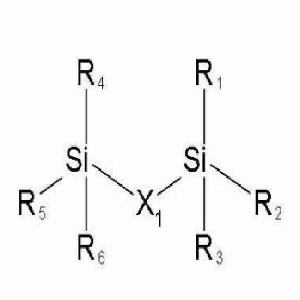
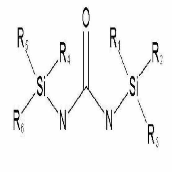


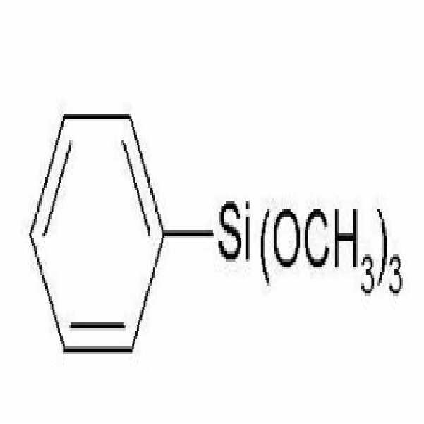

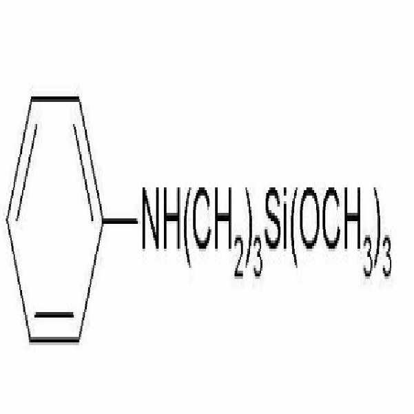
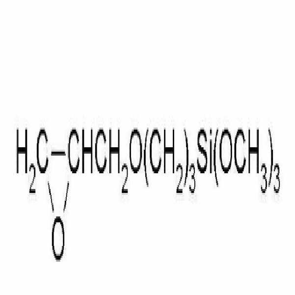
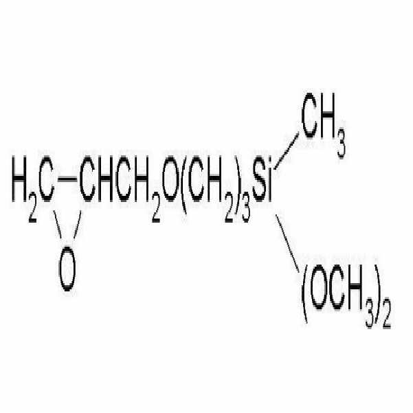
Priority Applications (4)
| Application Number | Priority Date | Filing Date | Title |
|---|---|---|---|
| KR1020050066867A KR100709860B1 (en) | 2005-07-22 | 2005-07-22 | An electrode comprising a Si-containing material layer and a porous membrane and a lithium battery employing the same |
| US11/490,146 US8741488B2 (en) | 2005-07-22 | 2006-07-21 | Electrode including Si-containing material layer and porous film, and lithium battery employing the same |
| EP06117731A EP1746674B1 (en) | 2005-07-22 | 2006-07-24 | Electrode including si-containing material layer and porous film, and lithium battery employing the same |
| DE602006013230T DE602006013230D1 (en) | 2005-07-22 | 2006-07-24 | Electrode containing a silicon composition layer and porous film, and lithium battery with this electrode |
Applications Claiming Priority (1)
| Application Number | Priority Date | Filing Date | Title |
|---|---|---|---|
| KR1020050066867A KR100709860B1 (en) | 2005-07-22 | 2005-07-22 | An electrode comprising a Si-containing material layer and a porous membrane and a lithium battery employing the same |
Publications (1)
| Publication Number | Publication Date |
|---|---|
| KR100709860B1 true KR100709860B1 (en) | 2007-04-23 |
Family
ID=37027725
Family Applications (1)
| Application Number | Title | Priority Date | Filing Date |
|---|---|---|---|
| KR1020050066867A Expired - Fee Related KR100709860B1 (en) | 2005-07-22 | 2005-07-22 | An electrode comprising a Si-containing material layer and a porous membrane and a lithium battery employing the same |
Country Status (4)
| Country | Link |
|---|---|
| US (1) | US8741488B2 (en) |
| EP (1) | EP1746674B1 (en) |
| KR (1) | KR100709860B1 (en) |
| DE (1) | DE602006013230D1 (en) |
Cited By (2)
| Publication number | Priority date | Publication date | Assignee | Title |
|---|---|---|---|---|
| KR101428710B1 (en) | 2008-01-08 | 2014-08-08 | 삼성에스디아이 주식회사 | Electrode assembly and secondary battery having same |
| CN111418092A (en) * | 2017-10-31 | 2020-07-14 | 科技创新动量基金(以色列)参股有限公司 | Nanostructured composite electrodes |
Families Citing this family (20)
| Publication number | Priority date | Publication date | Assignee | Title |
|---|---|---|---|---|
| JP2007273123A (en) * | 2006-03-30 | 2007-10-18 | Matsushita Electric Ind Co Ltd | Nonaqueous electrolyte secondary battery and manufacturing method thereof |
| CN101438434B (en) * | 2006-05-04 | 2017-09-15 | 株式会社Lg化学 | Electrode active material with high stability and electrochemical device using same |
| KR101031880B1 (en) * | 2008-01-08 | 2011-05-02 | 삼성에스디아이 주식회사 | Electrode assembly and lithium secondary battery having same |
| CN101952995B (en) * | 2008-02-15 | 2014-07-30 | 美商源捷有限公司 | Method of electrically connecting cell terminals in a battery pack |
| JP2010244936A (en) * | 2009-04-08 | 2010-10-28 | Sony Corp | Negative electrode and non-aqueous electrolyte secondary battery |
| CN102225948A (en) * | 2011-05-05 | 2011-10-26 | 厦门大学 | Silicon trithiol and its preparation method |
| US9450223B2 (en) | 2012-02-06 | 2016-09-20 | Samsung Sdi Co., Ltd. | Lithium secondary battery |
| KR101683212B1 (en) | 2012-02-07 | 2016-12-06 | 삼성에스디아이 주식회사 | Method of preparing lithium secondary battery |
| KR101507453B1 (en) * | 2012-04-18 | 2015-03-31 | 주식회사 엘지화학 | Anode Active Material and The Secondary Battery Comprising the Same |
| CN103633333A (en) * | 2012-08-24 | 2014-03-12 | 海洋王照明科技股份有限公司 | Nitrogen-doped or boron-doped graphene/aluminum foil composite current collector, preparation method thereof, electrochemical electrode and electrochemical cell or capacitor |
| CN104659399B (en) * | 2013-11-20 | 2017-05-17 | 万向一二三股份公司 | Infiltration method of high compaction density anode power battery |
| KR101601919B1 (en) * | 2013-12-12 | 2016-03-09 | 울산과학기술원 | Negative electrode active material, methode for manufacturing the same, and lithium rechargable battery including the same |
| KR101950448B1 (en) | 2015-07-10 | 2019-02-20 | 주식회사 엘지화학 | The electrode assembly and manufacturing method of thereof |
| FR3076062B1 (en) * | 2017-12-21 | 2020-07-17 | Commissariat A L'energie Atomique Et Aux Energies Alternatives | REALIZATION OF A MICROELECTRONIC DEVICE COLLECTOR |
| CN111712942A (en) | 2018-01-08 | 2020-09-25 | 24M技术公司 | Electrochemical cell including permselective membrane, system and method of making the same |
| IT201800004325A1 (en) * | 2018-04-09 | 2019-10-09 | Flow battery | |
| US11631920B2 (en) | 2019-06-27 | 2023-04-18 | 24M Technologies, Inc. | Dual electrolyte electrochemical cells, systems, and methods of manufacturing the same |
| WO2022094466A1 (en) * | 2020-11-02 | 2022-05-05 | 24M Technologies, Inc. | Electrochemical cells with dendrite prevention mechanisms and methods of making the same |
| CN115979907B (en) * | 2021-10-14 | 2024-11-19 | 比亚迪股份有限公司 | Electrode slice and pore detection method thereof |
| CN116259927B (en) * | 2023-05-15 | 2023-08-04 | 蔚来电池科技(安徽)有限公司 | Secondary battery and device |
Citations (6)
| Publication number | Priority date | Publication date | Assignee | Title |
|---|---|---|---|---|
| JP2000208134A (en) * | 1998-11-12 | 2000-07-28 | Dainippon Printing Co Ltd | Electrode plate for non-aqueous electrolyte secondary battery and method for producing the same |
| KR20020085675A (en) * | 2001-05-09 | 2002-11-16 | 주식회사 엘지화학 | New electrolyte and lithium ion battery using the same |
| JP2003217575A (en) | 2002-01-25 | 2003-07-31 | Nec Tokin Tochigi Ltd | Lithium ion secondary battery |
| KR100404733B1 (en) | 2001-06-12 | 2003-11-07 | 한국과학기술연구원 | Current collector coated with metal, electrodes comprising it, and lithium batteries comprising the electrodes |
| JP2005093084A (en) | 2003-09-12 | 2005-04-07 | Sanyo Electric Co Ltd | Usage method of lithium secondary battery |
| KR20050035282A (en) * | 2002-08-24 | 2005-04-15 | 크레아피스 게젤샤프트 퓌르 테흐놀로기 운트 인노파티온 엠베하 | Separator-electrode unit for lithium-ion batteries, method for the production and use thereof in lithium batteries |
Family Cites Families (20)
| Publication number | Priority date | Publication date | Assignee | Title |
|---|---|---|---|---|
| US4385101A (en) * | 1980-04-28 | 1983-05-24 | Catanzarite Vincent Owen | Electrochemical cell structure |
| US4416915A (en) | 1982-02-04 | 1983-11-22 | Combustion Engineering, Inc. | Method of making chalcogenide cathodes |
| DE3702480A1 (en) * | 1987-01-28 | 1988-08-11 | Philips Patentverwaltung | METHOD FOR PRODUCING A MAGNETO-OPTICAL STORAGE |
| JPH0828000B2 (en) * | 1987-05-27 | 1996-03-21 | 株式会社リコー | Ferroelectric polymer optical memory − |
| JP2726285B2 (en) | 1988-10-31 | 1998-03-11 | 三菱化学株式会社 | Rechargeable battery |
| US5246782A (en) * | 1990-12-10 | 1993-09-21 | The Dow Chemical Company | Laminates of polymers having perfluorocyclobutane rings and polymers containing perfluorocyclobutane rings |
| DE69302596T2 (en) | 1992-02-04 | 1996-09-26 | Sharp Kk | Carbon composite electrode material |
| JP3369589B2 (en) | 1992-04-07 | 2003-01-20 | 三菱化学株式会社 | Electrode material |
| JP2960834B2 (en) | 1993-06-07 | 1999-10-12 | シャープ株式会社 | Lithium secondary battery |
| US5354631A (en) | 1993-06-08 | 1994-10-11 | Valence Technology, Inc. | Enhanced lithium surface |
| JPH07296802A (en) | 1994-04-26 | 1995-11-10 | Sumitomo Chem Co Ltd | Method for manufacturing electrode for lithium secondary battery and lithium secondary battery |
| JPH07335623A (en) | 1994-06-10 | 1995-12-22 | Sony Corp | Plasma etching method |
| US6537703B2 (en) * | 1998-11-12 | 2003-03-25 | Valence Technology, Inc. | Polymeric mesoporous separator elements for laminated lithium-ion rechargeable batteries |
| EP1096591A1 (en) | 1999-10-26 | 2001-05-02 | MERCK PATENT GmbH | Polymer electrolyte membrane for use in lithium batteries |
| JP2001216961A (en) | 2000-02-04 | 2001-08-10 | Shin Etsu Chem Co Ltd | Silicon oxide for lithium ion secondary battery and lithium ion secondary battery |
| US6798003B2 (en) * | 2001-07-20 | 2004-09-28 | Intel Corporation | Reliable adhesion layer interface structure for polymer memory electrode and method of making same |
| JP2003297701A (en) * | 2002-03-29 | 2003-10-17 | Tdk Corp | Electrochemical device and method of manufacturing the same |
| JP4025995B2 (en) * | 2002-11-26 | 2007-12-26 | 信越化学工業株式会社 | Nonaqueous electrolyte secondary battery negative electrode material, method for producing the same, and lithium ion secondary battery |
| KR100497231B1 (en) | 2003-07-08 | 2005-06-23 | 삼성에스디아이 주식회사 | Negative electrode for lithium secondary battery, method of preparing same, and lithium secondary battery comprising same |
| KR100646535B1 (en) * | 2005-03-23 | 2006-11-23 | 삼성에스디아이 주식회사 | Electrode assembly for lithium ion battery and lithium ion secondary battery using same |
-
2005
- 2005-07-22 KR KR1020050066867A patent/KR100709860B1/en not_active Expired - Fee Related
-
2006
- 2006-07-21 US US11/490,146 patent/US8741488B2/en not_active Expired - Fee Related
- 2006-07-24 EP EP06117731A patent/EP1746674B1/en not_active Ceased
- 2006-07-24 DE DE602006013230T patent/DE602006013230D1/en active Active
Patent Citations (6)
| Publication number | Priority date | Publication date | Assignee | Title |
|---|---|---|---|---|
| JP2000208134A (en) * | 1998-11-12 | 2000-07-28 | Dainippon Printing Co Ltd | Electrode plate for non-aqueous electrolyte secondary battery and method for producing the same |
| KR20020085675A (en) * | 2001-05-09 | 2002-11-16 | 주식회사 엘지화학 | New electrolyte and lithium ion battery using the same |
| KR100404733B1 (en) | 2001-06-12 | 2003-11-07 | 한국과학기술연구원 | Current collector coated with metal, electrodes comprising it, and lithium batteries comprising the electrodes |
| JP2003217575A (en) | 2002-01-25 | 2003-07-31 | Nec Tokin Tochigi Ltd | Lithium ion secondary battery |
| KR20050035282A (en) * | 2002-08-24 | 2005-04-15 | 크레아피스 게젤샤프트 퓌르 테흐놀로기 운트 인노파티온 엠베하 | Separator-electrode unit for lithium-ion batteries, method for the production and use thereof in lithium batteries |
| JP2005093084A (en) | 2003-09-12 | 2005-04-07 | Sanyo Electric Co Ltd | Usage method of lithium secondary battery |
Cited By (3)
| Publication number | Priority date | Publication date | Assignee | Title |
|---|---|---|---|---|
| KR101428710B1 (en) | 2008-01-08 | 2014-08-08 | 삼성에스디아이 주식회사 | Electrode assembly and secondary battery having same |
| CN111418092A (en) * | 2017-10-31 | 2020-07-14 | 科技创新动量基金(以色列)参股有限公司 | Nanostructured composite electrodes |
| US11929486B2 (en) | 2017-10-31 | 2024-03-12 | Technology Innovation Momentum Fund (Israel) Limited Partnership | Nanostructured composite electrodes |
Also Published As
| Publication number | Publication date |
|---|---|
| US20070020524A1 (en) | 2007-01-25 |
| EP1746674B1 (en) | 2010-03-31 |
| DE602006013230D1 (en) | 2010-05-12 |
| US8741488B2 (en) | 2014-06-03 |
| EP1746674A1 (en) | 2007-01-24 |
Similar Documents
| Publication | Publication Date | Title |
|---|---|---|
| KR100709860B1 (en) | An electrode comprising a Si-containing material layer and a porous membrane and a lithium battery employing the same | |
| KR102546315B1 (en) | Electrode composite separator assembly for lithium battery and lithium battery including the same | |
| CN101414680B (en) | Cathode active material, cathode, and non-aqueous electrolyte secondary battery | |
| CN105591057B (en) | Heat resisting micro pore film and battery diaphragm | |
| KR100686848B1 (en) | Lithium secondary battery | |
| KR102496375B1 (en) | Electrode composite separator assembly for lithium battery and lithium battery including the same | |
| EP1619733A1 (en) | Non-aqueous electrolyte battery | |
| US20080241684A1 (en) | Nonaqueous electrolyte secondary battery and method for manufacturing the same | |
| EP3951940B1 (en) | Method for preparing cathode active material for lithium secondary battery, and cathode active material prepared by preparation method | |
| CN101431151A (en) | Positive electrode and lithium ion secondary battery | |
| KR20230037451A (en) | An electrode for electrochemical device and an electrochemical device comprising the same | |
| WO2009084928A2 (en) | Pouch-type lithium secondary battery | |
| KR20190062310A (en) | Composition for gel polymer electrolyte, gel polymer electrolyte and lithium secondary battery comprising the same | |
| US9160004B2 (en) | Lithium ion secondary battery | |
| CN109804489B (en) | Positive electrode active material for secondary battery and secondary battery comprising same | |
| EP3923372A1 (en) | Separator stacked body for lithium secondary battery, and electrode assembly and lithium secondary battery comprising same | |
| JP4112988B2 (en) | Non-aqueous electrolyte additive for improving safety and lithium ion secondary battery including the same | |
| JP4995409B2 (en) | Cathode active material adsorbed with carbon compound and lithium battery employing the same | |
| US20250233263A1 (en) | Separator, preparation method thereof, and secondary battery and electric apparatus related thereto | |
| EP4040561A1 (en) | Electrolyte for lithium metal secondary battery | |
| KR102510889B1 (en) | Positive electrode for lithium secondary battery, preparing method thereof, and lithium secondary battery comprising the same | |
| JP7804122B2 (en) | Electrode for electrochemical element and electrochemical element including the same | |
| KR20220131673A (en) | Separator for lithium secondary battery and lithium secondary battery comprising same | |
| US20250079632A1 (en) | Separator for lithium secondary battery and lithium secondary battery comprising same | |
| KR20060118962A (en) | An electrode including a Si-containing material layer and a lithium battery employing the same |
Legal Events
| Date | Code | Title | Description |
|---|---|---|---|
| A201 | Request for examination | ||
| PA0109 | Patent application |
St.27 status event code: A-0-1-A10-A12-nap-PA0109 |
|
| PA0201 | Request for examination |
St.27 status event code: A-1-2-D10-D11-exm-PA0201 |
|
| D13-X000 | Search requested |
St.27 status event code: A-1-2-D10-D13-srh-X000 |
|
| D14-X000 | Search report completed |
St.27 status event code: A-1-2-D10-D14-srh-X000 |
|
| E902 | Notification of reason for refusal | ||
| PE0902 | Notice of grounds for rejection |
St.27 status event code: A-1-2-D10-D21-exm-PE0902 |
|
| AMND | Amendment | ||
| E13-X000 | Pre-grant limitation requested |
St.27 status event code: A-2-3-E10-E13-lim-X000 |
|
| P11-X000 | Amendment of application requested |
St.27 status event code: A-2-2-P10-P11-nap-X000 |
|
| P13-X000 | Application amended |
St.27 status event code: A-2-2-P10-P13-nap-X000 |
|
| E601 | Decision to refuse application | ||
| PE0601 | Decision on rejection of patent |
St.27 status event code: N-2-6-B10-B15-exm-PE0601 |
|
| J201 | Request for trial against refusal decision | ||
| PJ0201 | Trial against decision of rejection |
St.27 status event code: A-3-3-V10-V11-apl-PJ0201 |
|
| AMND | Amendment | ||
| E13-X000 | Pre-grant limitation requested |
St.27 status event code: A-2-3-E10-E13-lim-X000 |
|
| P11-X000 | Amendment of application requested |
St.27 status event code: A-2-2-P10-P11-nap-X000 |
|
| P13-X000 | Application amended |
St.27 status event code: A-2-2-P10-P13-nap-X000 |
|
| PB0901 | Examination by re-examination before a trial |
St.27 status event code: A-6-3-E10-E12-rex-PB0901 |
|
| B701 | Decision to grant | ||
| PB0701 | Decision of registration after re-examination before a trial |
St.27 status event code: A-3-4-F10-F13-rex-PB0701 |
|
| PR1002 | Payment of registration fee |
St.27 status event code: A-2-2-U10-U11-oth-PR1002 Fee payment year number: 1 |
|
| GRNT | Written decision to grant | ||
| PR0701 | Registration of establishment |
St.27 status event code: A-2-4-F10-F11-exm-PR0701 |
|
| PG1601 | Publication of registration |
St.27 status event code: A-4-4-Q10-Q13-nap-PG1601 |
|
| R18-X000 | Changes to party contact information recorded |
St.27 status event code: A-5-5-R10-R18-oth-X000 |
|
| PR1001 | Payment of annual fee |
St.27 status event code: A-4-4-U10-U11-oth-PR1001 Fee payment year number: 4 |
|
| R18-X000 | Changes to party contact information recorded |
St.27 status event code: A-5-5-R10-R18-oth-X000 |
|
| PR1001 | Payment of annual fee |
St.27 status event code: A-4-4-U10-U11-oth-PR1001 Fee payment year number: 5 |
|
| FPAY | Annual fee payment |
Payment date: 20120326 Year of fee payment: 6 |
|
| PR1001 | Payment of annual fee |
St.27 status event code: A-4-4-U10-U11-oth-PR1001 Fee payment year number: 6 |
|
| FPAY | Annual fee payment |
Payment date: 20130322 Year of fee payment: 7 |
|
| PR1001 | Payment of annual fee |
St.27 status event code: A-4-4-U10-U11-oth-PR1001 Fee payment year number: 7 |
|
| R18-X000 | Changes to party contact information recorded |
St.27 status event code: A-5-5-R10-R18-oth-X000 |
|
| PR1001 | Payment of annual fee |
St.27 status event code: A-4-4-U10-U11-oth-PR1001 Fee payment year number: 8 |
|
| PR1001 | Payment of annual fee |
St.27 status event code: A-4-4-U10-U11-oth-PR1001 Fee payment year number: 9 |
|
| FPAY | Annual fee payment |
Payment date: 20160323 Year of fee payment: 10 |
|
| PR1001 | Payment of annual fee |
St.27 status event code: A-4-4-U10-U11-oth-PR1001 Fee payment year number: 10 |
|
| FPAY | Annual fee payment |
Payment date: 20170324 Year of fee payment: 11 |
|
| PR1001 | Payment of annual fee |
St.27 status event code: A-4-4-U10-U11-oth-PR1001 Fee payment year number: 11 |
|
| FPAY | Annual fee payment |
Payment date: 20180320 Year of fee payment: 12 |
|
| PR1001 | Payment of annual fee |
St.27 status event code: A-4-4-U10-U11-oth-PR1001 Fee payment year number: 12 |
|
| FPAY | Annual fee payment |
Payment date: 20190402 Year of fee payment: 13 |
|
| PR1001 | Payment of annual fee |
St.27 status event code: A-4-4-U10-U11-oth-PR1001 Fee payment year number: 13 |
|
| FPAY | Annual fee payment |
Payment date: 20200305 Year of fee payment: 14 |
|
| PR1001 | Payment of annual fee |
St.27 status event code: A-4-4-U10-U11-oth-PR1001 Fee payment year number: 14 |
|
| PC1903 | Unpaid annual fee |
St.27 status event code: A-4-4-U10-U13-oth-PC1903 Not in force date: 20210414 Payment event data comment text: Termination Category : DEFAULT_OF_REGISTRATION_FEE |
|
| R18-X000 | Changes to party contact information recorded |
St.27 status event code: A-5-5-R10-R18-oth-X000 |
|
| PC1903 | Unpaid annual fee |
St.27 status event code: N-4-6-H10-H13-oth-PC1903 Ip right cessation event data comment text: Termination Category : DEFAULT_OF_REGISTRATION_FEE Not in force date: 20210414 |