KR100708352B1 - 3D shape measuring device and method for performing 2π ambiguity of moiré principle and no means of phase shifting - Google Patents
3D shape measuring device and method for performing 2π ambiguity of moiré principle and no means of phase shifting Download PDFInfo
- Publication number
- KR100708352B1 KR100708352B1 KR1020060021319A KR20060021319A KR100708352B1 KR 100708352 B1 KR100708352 B1 KR 100708352B1 KR 1020060021319 A KR1020060021319 A KR 1020060021319A KR 20060021319 A KR20060021319 A KR 20060021319A KR 100708352 B1 KR100708352 B1 KR 100708352B1
- Authority
- KR
- South Korea
- Prior art keywords
- ambiguity
- pattern
- dimensional shape
- camera
- fringe
- Prior art date
- Legal status (The legal status is an assumption and is not a legal conclusion. Google has not performed a legal analysis and makes no representation as to the accuracy of the status listed.)
- Expired - Fee Related
Links
Images


Classifications
-
- G—PHYSICS
- G01—MEASURING; TESTING
- G01B—MEASURING LENGTH, THICKNESS OR SIMILAR LINEAR DIMENSIONS; MEASURING ANGLES; MEASURING AREAS; MEASURING IRREGULARITIES OF SURFACES OR CONTOURS
- G01B11/00—Measuring arrangements characterised by the use of optical techniques
- G01B11/24—Measuring arrangements characterised by the use of optical techniques for measuring contours or curvatures
- G01B11/25—Measuring arrangements characterised by the use of optical techniques for measuring contours or curvatures by projecting a pattern, e.g. one or more lines, moiré fringes on the object
-
- D—TEXTILES; PAPER
- D06—TREATMENT OF TEXTILES OR THE LIKE; LAUNDERING; FLEXIBLE MATERIALS NOT OTHERWISE PROVIDED FOR
- D06Q—DECORATING TEXTILES
- D06Q1/00—Decorating textiles
- D06Q1/08—Decorating textiles by fixation of mechanical effects, e.g. calendering, embossing or Chintz effects, using chemical means
Landscapes
- Engineering & Computer Science (AREA)
- Computer Vision & Pattern Recognition (AREA)
- Physics & Mathematics (AREA)
- General Physics & Mathematics (AREA)
- Textile Engineering (AREA)
- Length Measuring Devices By Optical Means (AREA)
Abstract
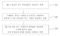
본 발명은 모아레 원리의 2π 모호성이 없도록 실시되는 3차원 형상 측정장치 및 그 방법에 관한 것으로서, 패턴 주기를 자유롭게 조절하는 패턴 주사기(10)로 측정 대상물(50)에 주기적으로 빛을 주사하고서, 제1 카메라(20)가 검출하는 하나의 프린지 영상에서의 임의의 지점(R1)의 프린지 무늬와 동일한 프린지 무늬를 참조면(60)상에서 검출하여, 2π 모호성을 갖는 후보점들로 인식하는 제1 단계(S1)와; 2π 모호성을 갖는 후보점들 중에서 제1 카메라(20)의 좌측에 위치하는 제2 카메라(30)로 임의의 지점(R1)의 프린지 무늬와 동일한 대응점이 있는지를 판단하는 제2 단계(S2); 및 동일하다고 판단된 대응점의 결과값을 이용하여 모아레 원리에 따라 측정 대상물(50)의 3차원 형상을 측정하는 제3 단계(S3)에 의해 실시되는 것을 특징으로 한다. 이로 인해, 본 발명의 3차원 형상 측정장치 및 그 방법은 모아레 원리를 이용하면서도 2π 모호성의 오류를 제거하기 때문에, 3차원 형상 정보를 보다 빠르고 정확하게 측정할 수 있는 장점이 있다. 또한, 본 발명은 패턴 주사기에서 패턴 영상을 조절하기 때문에, 종래기술과 다르게 측정 대상물을 위상천이시킬 하드웨어 수단이 필요없는 장점이 있다. The present invention relates to a three-dimensional shape measuring apparatus and a method which is implemented so as to avoid the 2π ambiguity of the moiré principle, and by periodically injecting light to the measurement target 50 with a pattern syringe 10 for freely adjusting the pattern period, A first fringe pattern identical to the fringe pattern of an arbitrary point R 1 in one fringe image detected by one camera 20 is detected on the reference surface 60 and recognized as candidate points having 2π ambiguity. Step S1; A second step S2 of determining whether the second camera 30 positioned on the left side of the first camera 20 among the candidate points having 2π ambiguity has the same correspondence with the fringe pattern at an arbitrary point R 1 ; ; And a third step S3 of measuring the three-dimensional shape of the measurement object 50 according to the moiré principle using the result value of the corresponding point determined to be the same. Thus, the three-dimensional shape measuring apparatus and the method of the present invention eliminates the error of 2π ambiguity while using the moiré principle, and thus has the advantage of measuring three-dimensional shape information more quickly and accurately. In addition, since the present invention controls the pattern image in the pattern syringe, unlike the prior art, there is an advantage that no hardware means for phase shifting the measurement object is required.
Description
도 1은 본 발명의 한 실시예에 따른 모아레 원리의 2π 모호성이 없도록 실시되는 3차원 형상 측정방법의 흐름도이고,1 is a flowchart of a three-dimensional shape measuring method performed so as not to have a 2π ambiguity of the moire principle according to an embodiment of the present invention,
도 2는 도 1에 도시된 3차원 형상 측정방법을 구현하기 위한 패턴 주사기와 2대의 카메라를 이용하는 3차원 형상 측정장치의 개략도이고,2 is a schematic diagram of a three-dimensional shape measuring apparatus using a pattern syringe and two cameras for implementing the three-dimensional shape measuring method shown in FIG.
도 3 및 도 4는 도 2에 도시된 3차원 형상 측정장치를 이용하여 도 1에 도시된 3차원 형상 측정방법의 제1, 제2 단계를 수행하는 상태를 각각 나타낸 개략도이고,3 and 4 are schematic views showing a state in which the first and second steps of the three-dimensional shape measuring method shown in FIG. 1 are performed using the three-dimensional shape measuring device shown in FIG. 2, respectively.
도 5는 도 2에 도시된 3차원 형상 측정장치의 실제 사진(a)과 그 상대적인 위치를 나타낸 개략도(b)이고,FIG. 5 is a schematic view (b) showing an actual photograph (a) and its relative position of the three-dimensional shape measuring apparatus shown in FIG.
도 6 내지 도 8은 종래기술에 따른 3차원 형상 측정방법과 본 발명의 한 실시예에 따른 3차원 형상 측정방법을 이용하여 각각의 측정 대상물들을 측정한 결과를 나타낸 도면들이다.6 to 8 are diagrams showing the results of measuring the respective measurement targets using the three-dimensional shape measurement method according to the prior art and the three-dimensional shape measurement method according to an embodiment of the present invention.
< 도면의 주요부분에 대한 부호의 설명 > <Description of Symbols for Major Parts of Drawings>
10 : 패턴 주사기 20, 30 : 카메라10:
40 : 제어부 50 : 측정 대상물40: control unit 50: measurement object
60 : 참조면60: reference plane
본 발명은 모아레 원리를 이용하는 3차원 형상 측정장치 및 그 방법에 관한 것이며, 더욱 상세하게는 모아레 원리를 이용하는 측정방법에서 발생되는 2π 모호성의 오류가 발생되지 않도록 구현함으로써 측정 대상물의 영상을 보다 정확하게 측정할 수 있는 3차원 형상 측정장치 및 그 방법에 관한 것이다.The present invention relates to a three-dimensional shape measuring apparatus using the moiré principle and a method thereof, and more particularly to accurately measure the image of the measurement target by implementing the 2π ambiguity error generated in the measurement method using the moiré principle does not occur The present invention relates to a three-dimensional shape measuring apparatus that can be used, and a method thereof.
3차원 형상 측정기술은 레이저를 이용하는 광삼각법, 스테레오를 이용하는 측정방법, 모아레 원리를 이용하는 측정방법 등이 개발 사용되고 있다. 그 중에서도 모아레 원리를 이용하는 3차원 형상 측정방법이 그 정밀도가 우수하여 널리 사용되고 있다. 하지만, 모아레 원리를 이용하는 3차원 형상 측정방법은 주사되는 패턴의 주기보다 2π 이상이 되는 높이를 갖는 측정 대상물인 경우에 측정이 되지 않는 2π 모호성이 존재한다. 그래서, 종래에는 측정하고자 하는 지점의 위상변위가 주변 지점에 비해 2π 이상으로 차이가 나는 경우에 측정지점의 높이값에 ±2π를 보정하고서 이를 결과값에 반영하는 방식으로 2π 모호성의 문제점을 해결하였 다. 하지만, 종래기술에 따른 모아레 원리를 이용하는 3차원 형상 측정방법은 2개의 측정 대상물들이 2π 이상으로 상호 떨어져 위치하는 경우에 그 측정 결과값이 2π 모호성에 의한 결과인지 아니면 2π 이상의 깊이를 갖는 측정 대상물인지를 구분하기가 어려워서, 부정확한 결과가 발생될 수 있는 문제점이 여전히 존재한다. 그래서, 종래에는 다른 방식에 의해 2π 모호성을 해결하기 위해 노력이 있었다. Three-dimensional shape measurement technology has been developed and used, such as optical triangulation using a laser, a measurement method using a stereo, a measurement method using the moire principle. Among them, the three-dimensional shape measuring method using the moiré principle is widely used because of its excellent precision. However, in the three-dimensional shape measuring method using the moire principle, there is a 2π ambiguity that cannot be measured in the case of a measuring object having a height of 2π or more than the period of the scanned pattern. Thus, when the phase shift of the point to be measured differs by more than 2π from the surrounding point, the problem of 2π ambiguity is solved by correcting ± 2π to the height value of the measuring point and reflecting it in the result value. All. However, the three-dimensional shape measurement method using the moiré principle according to the prior art is that when the two measurement objects are located at least 2π apart from each other whether the measurement result is a result of 2π ambiguity or a measurement object having a depth of 2π or more There is still a problem that can be difficult to distinguish, which may result in inaccurate results. Thus, in the past, efforts have been made to solve the 2π ambiguity by other methods.
대한민국 특허공개 제10-2005-0031328호에 기술된 "스테레오 비전과 모아레를 이용한 3차원 검사방법 및 장치"의 특허기술은 광투영부가 일정한 패턴을 수 차례 주사하고, 측정 대상물을 모터로 위상천이시키면서, 두 대의 카메라들로 각각 측정 대상물을 측정한다. 이와 같은 방식에 의한 특허기술은 측정 대상물을 위상천이시키면서 매 시점마다 3차원 형상정보를 축적할 수 있고, 이렇게 측정된 수많은 3차원 형상정보들을 상호 비교함으로써 최종적으로 측정 대상물의 3차원 형상정보를 측정할 수 있다. 하지만, 이러한 특허기술은 2π 모호성이 배제된 측정 대상물의 3차원 형상정보를 비교적 정확하게 측정할 수 있더라도, 측정 대상물을 위상 천이시켜야 하는 모터와 같은 하드웨어 수단을 구비해야 할 뿐만 아니라 측정 대상물에 대한 수많은 3차원 형상정보들을 상호 비교하는데 시간이 소요됨으로 그 처리시간이 길어지는 문제점이 있다.The patented technology of "Three-dimensional inspection method and apparatus using stereo vision and moiré" described in Korean Patent Publication No. 10-2005-0031328, while the light projection unit scans a certain pattern several times, and phase shifts the measurement object with a motor. Each camera measures two objects. In this method, the patented technology can accumulate three-dimensional shape information at every time while phase shifting the measurement object, and finally measure the three-dimensional shape information of the measurement object by comparing a large number of three-dimensional shape information measured in this way. can do. However, even if the patented technology can measure the three-dimensional shape information of the measurement object excluding 2π ambiguity relatively accurately, it is not only necessary to provide hardware means such as a motor to phase shift the measurement object, It takes a long time to compare the dimensional shape information with each other, the processing time is long.
본 발명은 앞서 설명한 바와 같은 종래 기술의 문제점을 해결하기 위하여 제공된 것으로서, 모아레 원리를 이용하면서도 2π 모호성이 없도록 3차원 형상을 보 다 정확하게 측정하는 3차원 형상 측정장치 및 그 방법을 제공하는데 그 목적이 있다.The present invention has been made to solve the problems of the prior art as described above, and to provide a three-dimensional shape measuring apparatus and method for measuring the three-dimensional shape more accurately without using the moiré principle 2π ambiguity have.
또한, 본 발명은 종래기술과 달리 측정 대상물을 위상천이시키기 위한 하드웨어 수단이 필요없으면서도, 3차원 형상의 측정 결과값도 신속하게 확인할 수 있는 3차원 형상 측정장치를 제공하는데 다른 목적이 있다. Another object of the present invention is to provide a three-dimensional shape measuring apparatus capable of quickly confirming a measurement result value of a three-dimensional shape without requiring hardware means for phase shifting a measurement object unlike the prior art.
앞서 설명한 바와 같은 목적을 달성하기 위한 본 발명에 따른 모아레 원리의 2π 모호성과 위상천이 수단이 없도록 실시되는 3차원 형상 측정방법은 패턴 주기를 자유롭게 조절하는 패턴 주사기로 측정 대상물에 주기적으로 빛을 주사하고서, 제1 카메라가 검출하는 하나의 프린지 영상에서의 임의의 지점의 프린지 무늬와 동일한 프린지 무늬를 참조면상에서 검출하여 2π 모호성을 갖는 후보점들로 인식하는 제1 단계와; 상기 2π 모호성을 갖는 후보점들 중에서 상기 제1 카메라의 좌측에 위치하는 제2 카메라로 상기 임의의 지점의 프린지 무늬와 동일한 대응점이 있는지를 판단하는 제2 단계; 및 상기 동일하다고 판단된 대응점의 결과값을 이용하여 모아레 원리에 따라 상기 측정 대상물의 3차원 형상을 측정하는 제3 단계를 포함하는 것을 특징으로 한다. The three-dimensional shape measuring method implemented so that there is no 2π ambiguity and phase shifting means of the moiré principle according to the present invention for achieving the object as described above is to periodically scan the light to the measurement object with a pattern syringe to freely control the pattern period A first step of detecting a fringe pattern identical to a fringe pattern of an arbitrary point in one fringe image detected by the first camera on a reference surface and recognizing them as candidate points having 2π ambiguity; A second step of determining whether the second camera located on the left side of the first camera among the candidate points having the 2π ambiguity has the same correspondence point as the fringe pattern of the arbitrary point; And a third step of measuring the three-dimensional shape of the measurement object according to the moiré principle using the result value of the corresponding point determined to be the same.
또한, 본 발명에 따른 모아레 원리의 2π 모호성과 위상천이 수단이 없도록 실시되는 3차원 형상 측정장치는 빛을 주기적으로 주사하는 패턴 주사기와, 상기 패턴 주사기의 빛에 의해 투영된 프린지 무늬를 각각 검출하는 제1, 제2 카메라, 및 상기 패턴 주사기와 상기 제1, 제2 카메라들의 작동을 제어하는 제어부를 포함한다. 특히, 본 발명의 상기 패턴 주사기는 그 내부에 설치되어 빛을 주사하는 광원과, 상기 광원에서 주사된 빛을 반사시키도록 자체 회전하는 회전 다면 거울, 및 상기 회전 다면 거울에서 반사된 빛의 일부를 검출하는 광검출기를 포함하고; 상기 제1 카메라는 2π 모호성을 갖는 후보점들을 검출하기 위해 임의의 지점의 프린지 무늬를 검출하며; 상기 제2 카메라는 상기 제1 카메라의 좌측에 위치하면서, 상기 2π 모호성을 갖는 후보점들 중에서 상기 제1 카메라와 동일한 프린지 무늬를 갖는 대응점이 있는지를 검출하고; 상기 제어부는 상기 패턴 주사기의 광검출기에서 측정되는 빛의 피드백 정보에 기초하여 정해진 프로그램에 따라 상기 회전 다면 거울의 회전속도와 상기 광원의 온/오프(On/Off) 시간을 제어하는 것을 특징으로 한다. In addition, the three-dimensional shape measuring apparatus implemented so that there is no 2π ambiguity and phase shift means of the moiré principle according to the present invention is to detect a pattern syringe for periodically scanning light, and a fringe pattern projected by the light of the pattern syringe, respectively And a control unit for controlling operations of the first and second cameras and the pattern syringe and the first and second cameras. In particular, the pattern syringe of the present invention has a light source installed therein to scan light, a rotating multi-face mirror that rotates itself to reflect the light injected from the light source, and a portion of the light reflected from the rotating multi-face mirror A photodetector for detecting; The first camera detects a fringe pattern at any point to detect candidate points with 2π ambiguity; The second camera is located on the left side of the first camera and detects whether there is a corresponding point having the same fringe pattern as the first camera among candidate points having the 2π ambiguity; The control unit may control the rotation speed of the rotating multi-faceted mirror and the on / off time of the light source according to a predetermined program based on feedback information of light measured by the photodetector of the pattern syringe. .
아래에서는 본 발명에 따른 모아레 원리를 이용하는 3차원 형상 측정장치 및 그 방법의 양호한 실시예를 첨부한 도면을 참조하면서 상세히 설명하겠다.Hereinafter, with reference to the accompanying drawings, preferred embodiments of a three-dimensional shape measuring apparatus and method using the moire principle according to the present invention will be described in detail.
본 발명에 따른 모아레 원리의 2π 모호성과 위상천이 수단이 없도록 실시되는 3차원 형상 측정방법은 모아레 원리를 이용하면서 도 1에 도시된 단계에 따라 실시되며, 도 2에 도시된 바와 같은 장치에 의해 구현된다.The three-dimensional shape measurement method performed without the 2π ambiguity and phase shifting means of the moiré principle according to the present invention is carried out according to the steps shown in FIG. 1 using the moiré principle, and implemented by an apparatus as shown in FIG. do.
본 발명에 사용되는 3차원 형상 측정장치는 패턴 주기를 자유롭게 조절하여 측정 대상물(50)에 주기적인 빛을 주사하는 패턴 주사기(10)와, 내외부의 파라미터(parameter)가 확인된 보정(calibration) 상태의 제1, 제2 카메라(20, 30)와, 패턴 주사기(10)의 작동을 제어하면서 제1, 제2 카메라(20, 30)에서 측정되는 영상들을 비교 분석하는 제어부(40)를 구비한다.The three-dimensional shape measuring apparatus used in the present invention includes a
특히, 본 발명의 패턴 주사기(10)는 그 내부에 설치되며 슬릿광인 빛(레이저)을 주사하는 광원(11)과, 광원(11)에서 주사된 빛을 측정 대상물(50)의 방향으로 반사시키는 회전 다면 거울(12)과, 회전 다면 거울(12)에서 반사되는 빛의 일부를 다시 다른 방향으로 반사시키는 반사 거울(13), 및 반사 거울(13)로부터 입사되는 빛의 크기를 측정하는 광검출기(14)를 포함한다. 그리고, 본 발명은 패턴 주사기(10)의 광검출기(14)에서 측정된 빛에 대한 피드백 정보가 제어부(40)로 전달된다. 그러면, 패턴 주사기(10)는 피드백 정보에 기초하여 제어부(40)에 입력된 프로그램에 따라 회전 다면 거울(12)의 회전속도와 광원(11)의 온/오프(On/Off) 작동시간이 조절되면서, 측정 대상물(50)의 방향으로 주사되는 빛의 패턴 주기가 조절된다. 이때, 본 발명의 패턴 주사기(10)에는 회전 다면 거울(12)의 회전속도와 광원(11)의 온/오프(On/Off) 작동시간을 조절하기 위해서, 회전 다면 거울(12)과 광원(11)에 연계되는 타이머(15)가 설치된다. In particular, the
이와 같은 구성의 3차원 형상 측정장치를 이용하여 본 발명은 모아레 원리의 2π 모호성이 없으면서도 종래기술과 달리 위상천이 수단이 필요없도록 측정 대상물의 3차원 형상을 다음과 같이 측정한다. By using the three-dimensional shape measuring device having such a configuration, the present invention measures the three-dimensional shape of the measurement object as follows so that phase shift means is not required unlike the prior art without the 2π ambiguity of the moire principle.
먼저, 본 발명은 3차원 형상 측정기술들 중에서 모아레(Moire) 원리를 이용하는 측정방법을 기초로 한다. 모아레 원리를 이용하는 측정방법에 대해 간단하게 설명하면, 측정 대상물의 전방에 규칙적인 줄무늬 격자를 위치시키고서 한 쪽에서 빛을 주사하면 측정 대상물의 표면에 격자의 그림자가 측정 대상물에 표시된다. 그러면, 모아레 원리 측정방법은 다른 쪽에서 카메라로 바라보면 격자 줄무늬와 격자의 그림자가 겹쳐지면서 물결모양의 등고선과 같은 모아레 무늬로 보여지고, 카메라에서 모아레 무늬를 분석함으로써, 높이 정보를 갖는 측정 대상물의 3차원 형상을 측정하는 것이다. 하지만, 모아레 원리를 이용하는 3차원 형상 측정방법은 종래기술의 문제점으로 지적한 바와 같이 모아레 무늬의 패턴 주기보다 2π 이상이 되는 높이를 갖는 측정 대상물의 측정시 오류가 발생된다. 그래서, 본 발명은 모아레 원리를 이용하는 3차원 형상 측정방법을 이용하더라도 다음과 같이 2π 모호성을 갖는 후보점들을 검출하고서, 이 후보점들 중에서 유일한 대응점의 결과값만을 이용함으로써 보다 정확한 측정 대상물의 3차원 형상정보를 측정한다.First, the present invention is based on a measurement method using the Moire principle among three-dimensional shape measurement techniques. Briefly describing the measurement method using the moiré principle, by placing a regular striped grid in front of the measurement object and scanning light from one side, the shadow of the grid on the surface of the measurement object is displayed on the measurement object. Then, the moiré principle measuring method is seen as a moire pattern like a wavy contour as the grid stripes and the shadow of the grid overlap when viewed from the camera from the other side, and by analyzing the moire pattern in the camera, 3 It is to measure the dimensional shape. However, in the three-dimensional shape measuring method using the moiré principle, as pointed out as a problem of the prior art, an error occurs when measuring a measurement object having a height of 2π or more than the pattern period of the moire fringe. Thus, the present invention detects candidate points with 2π ambiguity as follows, even using a three-dimensional shape measurement method using the moiré principle, and uses only the result values of the corresponding corresponding points among the candidate points to more accurately measure the three-dimensional object. Measure shape information.
본 발명의 제1 단계는 패턴 주기를 자유롭게 조절하는 패턴 주사기(10)로 참조면(60)에 미세한 다수의 격자를 형성하는 빛을 주사하고서, 제1 카메라로 검출하는 하나의 프린지 영상에서의 임의의 지점(R1)의 프린지 무늬와 동일한 프린지 무늬를 참조면(60)상에서 검출하여, 2π 모호성을 갖는 후보점들로 인식한다(S1).In the first step of the present invention, a
도 3을 살펴보면, 본 발명은 제1 카메라(20)의 전방에 위치하는 임의의 프린지 영상에서의 임의의 지점(R1)인 하나의 프린지 가장자리 지점과 제1 카메라(20)의 중심점(OR)을 연결하는 선(ℓR1)을 설정한다. 이러한 선(ℓR1)은 아래의 수학식(1)에 의해 구해진다. Referring to FIG. 3, according to the present invention, one fringe edge point, which is an arbitrary point R 1 in an arbitrary fringe image located in front of the
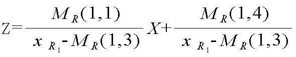
수학식(1)에서 Z는 선(ℓR1)의 공간좌표이고, XR1은 임의의 지점(R1)에 대한 영상좌표계의 X축 좌표이고, MR은 제1 카메라(20)의 주사행렬(projection matrix)이고, MR(i,j)은 제1 카메라(20)의 주사행렬의 i행 및 j열의 값을 지칭한다.In Equation (1), Z is the spatial coordinate of the line (L R1 ), X R1 is the X-axis coordinate of the image coordinate system for any point (R 1 ), M R is the scan matrix of the first camera 20 (projection matrix), and M R (i, j) refers to the values of rows i and j of the scanning matrix of the
그리고, 본 발명은 참조면(60)에 표시되는 프린지 무늬들 중에서 임의의 지점(R1)의 프린지 무늬와 동일한 무늬를 갖는 지점들을 찾아내고, 이렇게 찾아낸 프린지 무늬 지점들을 각각 패턴 주사기(10)의 중심점과 연결한다. 그러면, 패턴 주사기(10)와 참조면(60) 사이를 연결하는 선들은 제1 카메라(20)와 프린지 가장자리 지점을 연결하는 선(ℓR1)와 교차된다. 이와 같은 다수의 교차점들은 바로 모아레 원리에 의해 2π 모호성이 발생될 수 있는 측정 대상물의 높이지점이면서, 2π 모호성을 갖는 후보점(A, B, C, D)들이다. In addition, the present invention finds points having the same pattern as the fringe pattern of a certain point (R 1 ) among the fringe patterns displayed on the
본 발명의 제2 단계는 2π 모호성을 갖는 후보점(A, B, C, D)들 중에서 제1 카메라(20)의 좌측에 위치하는 제2 카메라(30)로 임의의 지점(R1)의 프린지 무늬와 동일한 대응점이 있는지를 판단한다(S2).A second step of the present invention of the candidate points (A, B, C, D ) any point of the
도 4를 살펴보면, 본 발명은 제1 카메라(20)의 좌측에 위치하는 제2 카메라(30)를 이용하여, 2π 모호성을 갖는 후보점(A, B, C, D)들의 프린지 무늬를 검출 한다. 그리고, 본 발명은 스테레오 정합을 이용한 알고리즘을 적용하여 아래와 같은 수학식(2)에 의해 임의의 지점(R1)의 프린지 무늬와 동일한 대응점이 있는지를 판단한다.Referring to FIG. 4, the present invention detects the fringes of candidate points A, B, C, and D having 2π ambiguity using the

수학식(2)에서 Xcand, Ycand, Zcand는 2π 모호성을 갖는 후보점(A, B, C, D)들의 월드 좌표계에서의 3차원 좌표이고, ML은 제2 카메라(30)의 주사행렬(projection matrix)이고, s는 크기에 대한 변수값(Scale factor)이다. In Equation (2), X cand , Y cand , and Z cand are three-dimensional coordinates in the world coordinate system of candidate points A, B, C, and D having 2π ambiguity, and M L is a value of the
본 발명의 제3 단계는 모든 행과 열의 프린지 가장자리 지점에 제1, 제2 단계를 반복함으로써, 최종적으로 동일하다고 판단된 2π 모호성을 갖는 유일한 대응점의 결과값을 이용하여 모아레 원리에 따라 측정 대상물의 3차원 형상을 측정한다(S3).The third step of the present invention repeats the first and second steps at the fringe edge points of all rows and columns, thereby using the result of the unique corresponding point having 2π ambiguity finally determined to be the same, according to the moiré principle. The three-dimensional shape is measured (S3).
단, 본 발명에 따른 모아레 원리의 2π 모호성이 없도록 실시되는 3차원 형상 측정방법은 다음과 같은 조건을 만족하는 것이 바람직하다. 첫째, 본 발명은 제1 카메라(20)에서 검출되는 패턴 영상이 그에 대응하는 제2 카메라(30)에서 검출되는 패턴 영상보다 오른쪽에 위치해야 한다. 둘째, 본 발명은 최종적으로 동일하다고 판단된 2π 모호성을 갖는 대응점에 대한 제1, 제2 카메라(20, 30)에서 검출 되는 패턴 영상들은 그 순서가 뒤섞이지 않고 각각 순서대로 진행된다. 셋째, 본 발명은 제1 카메라(20)에서의 패턴 영상들이 순서대로 진행되는 경우에 그에 대응하는 제2 카메라(30)에서의 패턴 영상들이 순서대로 위치한다면 몇 지점을 건너뛰면서 위치하더라도 무방하고, 이를 차단(occlusion)의 조건이라 한다.However, it is preferable that the three-dimensional shape measuring method performed without the 2π ambiguity of the moiré principle according to the present invention satisfies the following conditions. First, in the present invention, the pattern image detected by the
아래에서는 상기와 같은 본 발명에 따른 3차원 형상 측정방법과 종래기술에 따른 3차원 형상 측정방법으로 다양한 측정 대상물들을 각각 실험한 결과에 대해서 설명하겠다. Hereinafter, the results of experiments of various measurement objects, respectively, by the three-dimensional shape measuring method according to the present invention as described above and the three-dimensional shape measuring method according to the prior art will be described.
도 5는 도 2에 도시된 3차원 형상 측정장치의 실제 사진(a)과 그 상대적인 위치를 나타낸 개략도(b)이다. FIG. 5 is a schematic diagram (b) showing an actual photograph (a) and a relative position of the three-dimensional shape measuring apparatus shown in FIG. 2.
본 실험은 도 5에 도시된 바와 같은 하나의 패턴 주사기(10)와 제1, 제2 카메라(20, 30)를 구비한 장치를 사용하였다. 이때, 본 실험장치는 참조면(60)의 패턴 두께가 7mm이고, 참조면(60)과 왼쪽에 위치한 제2 카메라(30) 사이의 거리가 558.1392mm이고, 제1, 제2 카메라(20, 30) 사이의 거리가 13mm이고, 패턴 주사기(10)가 제2 카메라(30)로부터 X축의 (-)방향으로 81.9212mm, Z축의 (-)방향으로 105.8529mm 떨어져 위치한다.In this experiment, a device having one
도 6 내지 도 8은 종래기술에 따른 3차원 형상 측정방법과 본 발명의 한 실시예에 따른 3차원 형상 측정방법을 이용하여 각각의 측정 대상물들을 측정한 결과를 나타낸 도면들이다. 6 to 8 are diagrams showing the results of measuring the respective measurement targets using the three-dimensional shape measurement method according to the prior art and the three-dimensional shape measurement method according to an embodiment of the present invention.
실험1. 도 5에 도시된 본 실험장치를 이용하여 도 6의 (a)에 도시된 바와 같 은 물체의 두께가 50mm인 측정 대상물(51)을 측정하였다. 제1, 제2 카메라(20, 30)에서 검출되는 패턴 영상은 각각 도 6의 (c)와 같이 나타났다. 이때, 종래기술에 따른 3차원 형상 측정방법은 패턴 주사기(10)와 제1 카메라(20)만을 사용하고 모아레 원리에 따라 측정 대상물(51)을 측정하여, 도 6의 (d)와 같은 결과를 도출하였다. 그리고, 본 발명에 따른 3차원 형상 측정방법은 패턴 주사기(10)와 제1, 제2 카메라(20, 30)를 사용하고 모아레 원리에 따라 측정 대상물(51)을 측정하여, 도 6의 (e)와 같은 결과를 도출하였다. 즉, 측정 대상물(51)의 두께(50mm)가 패턴 주기의 2π보다 작기 때문에, 종래기술과 본 발명은 도 6의 (d) 및 (e)에 나타난 바와 같이 동일한 결과를 도출하였다.Experiment 1. Using the present experimental apparatus shown in FIG. 5, the
실험2. 도 5에 도시된 본 실험장치를 이용하여 도 7의 (a)에 도시된 바와 같이 물체의 두께가 80mm인 측정 대상물(52)을 참조면(60)으로부터 90mm 이격시킨 후에 측정하였다. 제1, 제2 카메라(20, 30)에서 검출되는 패턴 영상은 각각 도 7의 (c)와 같이 나타났다. 이때, 종래기술에 따른 3차원 형상 측정방법은 패턴 주사기(10)와 제1 카메라(20)만을 사용하고 모아레 원리에 따라 측정 대상물(52)을 측정하여, 도 7의 (d)와 같은 결과를 도출하였다. 그리고, 본 발명에 따른 3차원 형상 측정방법은 패턴 주사기(10)와 제1, 제2 카메라(20, 30)를 사용하고 모아레 원리에 따라 측정 대상물(52)을 측정하여, 도 7의 (e)와 같은 결과를 도출하였다. 즉, 종래기술에 따른 측정방법은 측정 대상물(52)이 참조면(60)으로부터 90mm가 이격된 상태로 패턴 주기의 2π보다 크기 때문에, 도 7의 (d)와 같이 실제 측정 대상물(52)의 공간정보와 다르게 표시되었지만, 본 발명에 따른 측정방법은 도 7의 (e)와 같이 실제와 동일한 3차원 형상 정보로 나타났다.
실험3. 도 5에 도시된 본 실험장치를 이용하여 도 8의 (a)에 도시된 바와 같이 물체의 깊이가 190mm인 반구형 측정 대상물(53)을 측정하였다. 제1, 제2 카메라(20, 30)에서 검출되는 패턴 영상은 각각 도 8의 (c)와 같이 나타났다. 이때, 종래기술에 따른 3차원 형상 측정방법은 패턴 주사기(10)와 제1 카메라(20)만을 사용하고 모아레 원리에 따라 측정 대상물(51)을 측정하여, 도 8의 (d)와 같은 결과를 도출하였다. 그리고, 본 발명에 따른 3차원 형상 측정방법은 패턴 주사기(10)와 제1, 제2 카메라(20, 30)를 사용하고 모아레 원리에 따라 측정 대상물(53)을 측정하여, 도 8의 (e)와 같은 결과를 도출하였다. 즉, 종래기술에 따른 측정방법은 측정 대상물(53)의 정확한 공간 정보를 확보하기가 불가능하였지만, 본 발명에 따른 측정방법은 도 8의 (e)와 같이 실제와 동일한 3차원 형상 정보를 획득하였다.Experiment 3. As shown in FIG. 8A, the
따라서, 본 발명에 따른 3차원 형상 측정방법은 실험1, 실험2, 실험3을 통해 나타난 바와 같이 종래기술과 달리 모아레 원리의 2π 모호성이 없으면서도 종래기술과 달리 측정 대상물을 위상천이시키는 하드웨어 수단이 없어도 3차원 형상을 정확하게 측정할 수 있었다.Therefore, the three-dimensional shape measuring method according to the present invention, unlike the prior art, as shown through Experiment 1,
앞서 상세히 설명한 바와 같이, 본 발명의 3차원 형상 측정장치 및 그 방법은 모아레 원리를 이용하면서도 2π 모호성의 오류를 제거하기 때문에, 3차원 형상 정보를 보다 빠르고 정확하게 측정할 수 있는 장점이 있다.As described in detail above, the three-dimensional shape measuring apparatus and method of the present invention eliminates errors of 2π ambiguity while using the moiré principle, and thus has the advantage of measuring three-dimensional shape information more quickly and accurately.
또한, 본 발명은 패턴 주사기에서 패턴 영상을 조절하기 때문에, 종래기술과 다르게 측정 대상물을 위상천이시킬 하드웨어 수단이 필요없는 장점이 있다. In addition, since the present invention controls the pattern image in the pattern syringe, unlike the prior art, there is an advantage that no hardware means for phase shifting the measurement object is required.
이상에서 본 발명에 따른 모아레 원리의 2π 모호성과 위상천이 수단이 없도록 실시되는 3차원 형상 측정방법에 대한 기술사상을 첨부도면과 함께 서술하였지만 이는 본 발명의 가장 양호한 실시예를 예시적으로 설명한 것이지 본 발명을 한정하는 것은 아니다. 또한, 이 기술분야의 통상의 지식을 가진 자이면 누구나 본 발명의 기술사상의 범주를 이탈하지 않는 범위 내에서 다양한 변형 및 모방이 가능함은 명백한 사실이다.In the above description, the technical idea of the three-dimensional shape measuring method performed without the 2π ambiguity and the phase shifting means of the moire principle according to the present invention has been described together with the accompanying drawings. It is not intended to limit the invention. In addition, it is obvious that any person skilled in the art can make various modifications and imitations without departing from the scope of the technical idea of the present invention.
Claims (5)

Priority Applications (2)
| Application Number | Priority Date | Filing Date | Title |
|---|---|---|---|
| KR1020060021319A KR100708352B1 (en) | 2006-03-07 | 2006-03-07 | 3D shape measuring device and method for performing 2π ambiguity of moiré principle and no means of phase shifting |
| US11/716,059 US7548324B2 (en) | 2006-03-07 | 2007-03-01 | Three-dimensional shape measurement apparatus and method for eliminating 2π ambiguity of moire principle and omitting phase shifting means |
Applications Claiming Priority (1)
| Application Number | Priority Date | Filing Date | Title |
|---|---|---|---|
| KR1020060021319A KR100708352B1 (en) | 2006-03-07 | 2006-03-07 | 3D shape measuring device and method for performing 2π ambiguity of moiré principle and no means of phase shifting |
Publications (1)
| Publication Number | Publication Date |
|---|---|
| KR100708352B1 true KR100708352B1 (en) | 2007-04-18 |
Family
ID=38181525
Family Applications (1)
| Application Number | Title | Priority Date | Filing Date |
|---|---|---|---|
| KR1020060021319A Expired - Fee Related KR100708352B1 (en) | 2006-03-07 | 2006-03-07 | 3D shape measuring device and method for performing 2π ambiguity of moiré principle and no means of phase shifting |
Country Status (2)
| Country | Link |
|---|---|
| US (1) | US7548324B2 (en) |
| KR (1) | KR100708352B1 (en) |
Cited By (5)
| Publication number | Priority date | Publication date | Assignee | Title |
|---|---|---|---|---|
| KR100919166B1 (en) * | 2007-04-02 | 2009-09-28 | 한국과학기술원 | Stereo Moire Measurement Apparatus and Method |
| KR101092422B1 (en) | 2010-01-14 | 2011-12-09 | 경북대학교 산학협력단 | Optical surface profilometer |
| KR101160804B1 (en) | 2011-07-27 | 2012-06-28 | 경북대학교 산학협력단 | Method for detecting of optical surface profilometer |
| KR20150078055A (en) * | 2013-12-30 | 2015-07-08 | 엘지이노텍 주식회사 | Stereo camera apparatus and rectification method of the same |
| CN116592789A (en) * | 2023-06-05 | 2023-08-15 | 上海飞机制造有限公司 | Method and device for determining shape of swing mirror and three-dimensional measuring device |
Families Citing this family (28)
| Publication number | Priority date | Publication date | Assignee | Title |
|---|---|---|---|---|
| US8792707B2 (en) | 2007-08-17 | 2014-07-29 | Renishaw Plc | Phase analysis measurement apparatus and method |
| GB0915904D0 (en) * | 2009-09-11 | 2009-10-14 | Renishaw Plc | Non-contact object inspection |
| SG172487A1 (en) * | 2009-12-07 | 2011-07-28 | Sony Corp | A three-dimensional imaging apparatus and a method of generating a three-dimensional image of an object |
| US8532340B2 (en) * | 2010-09-30 | 2013-09-10 | Empire Technology Development, Llc | Projecting patterns for high resolution texture extraction |
| KR101669412B1 (en) | 2010-11-01 | 2016-10-26 | 삼성전자주식회사 | Method and apparatus of measuring depth information for 3d camera |
| JP6072425B2 (en) * | 2012-04-13 | 2017-02-01 | 藤垣 元治 | Three-dimensional displacement measuring device |
| TWI546518B (en) * | 2012-04-20 | 2016-08-21 | 德律科技股份有限公司 | Three dimensional measurement system and three dimensional measurement method |
| KR101893771B1 (en) * | 2012-05-10 | 2018-08-31 | 삼성전자주식회사 | Apparatus and method for processing 3d information |
| WO2014016001A1 (en) * | 2012-07-25 | 2014-01-30 | Siemens Aktiengesellschaft | Colour coding for 3d measurement, more particularly for transparent scattering surfaces |
| US9030470B2 (en) * | 2012-08-14 | 2015-05-12 | Hong Kong Applied Science and Technology Research Institute Company Limited | Method and system for rapid three-dimensional shape measurement |
| US8908178B1 (en) * | 2013-03-05 | 2014-12-09 | The United States Of America As Represented By The Secretary Of The Navy | Method for atmospheric laser beam detection using remote sensing of off-axis scattering |
| DE102013208466B4 (en) * | 2013-05-08 | 2016-01-14 | Fraunhofer-Gesellschaft zur Förderung der angewandten Forschung e.V. | Device and method for the contactless measurement of surface contours |
| US9459094B2 (en) * | 2013-09-12 | 2016-10-04 | Hong Kong Applied Science and Technology Research Institute Company Limited | Color-encoded fringe pattern for three-dimensional shape measurement |
| DE102014207022A1 (en) * | 2014-04-11 | 2015-10-29 | Siemens Aktiengesellschaft | Depth determination of a surface of a test object |
| DE102015207328A1 (en) * | 2015-04-22 | 2016-10-27 | Siemens Aktiengesellschaft | Method for depth determination |
| DE102015208285A1 (en) * | 2015-05-05 | 2016-11-10 | Friedrich-Schiller-Universität Jena | DEVICE AND METHOD FOR SPATIAL MEASUREMENT OF SURFACES |
| KR102523972B1 (en) | 2015-10-27 | 2023-04-20 | 삼성전자주식회사 | Method of measuring distance using 3D depth sensor including optical shutter |
| JP6906239B2 (en) * | 2015-12-28 | 2021-07-21 | ザクト ロボティクス リミテッド | Adjustable registration frame |
| JP6695746B2 (en) * | 2016-06-27 | 2020-05-20 | 株式会社キーエンス | measuring device |
| CN106595519B (en) * | 2016-12-07 | 2019-09-20 | 西安知象光电科技有限公司 | A kind of flexible 3 D contour measuring method and device based on laser MEMS projection |
| CN106802138B (en) * | 2017-02-24 | 2019-09-24 | 先临三维科技股份有限公司 | A kind of 3 D scanning system and its scan method |
| JP6792928B2 (en) * | 2017-04-14 | 2020-12-02 | 一般財団法人電力中央研究所 | Weight loss prediction method, prediction device, and prediction program |
| JP6792927B2 (en) * | 2017-04-14 | 2020-12-02 | 一般財団法人電力中央研究所 | 3D shape measurement method |
| JP2019082452A (en) * | 2017-10-31 | 2019-05-30 | キヤノン株式会社 | Image generation method, image generation device, and defect determination method using the same |
| EP3992575B1 (en) | 2019-06-28 | 2024-11-27 | Koh Young Technology Inc. | Apparatus and method for determining three-dimensional shape of an object |
| CN115218820B (en) * | 2021-04-20 | 2025-08-08 | 上海图漾信息科技有限公司 | Structured light projection device, depth data measurement head, computing device and measurement method |
| CN112557218B (en) * | 2020-12-24 | 2024-03-19 | 中国建筑第八工程局有限公司 | Method to determine whether clay is damaged by stress by comparing intercepts |
| CN113137938B (en) * | 2021-04-13 | 2023-04-25 | 思看科技(杭州)股份有限公司 | Three-dimensional scanning system, method, computer equipment and storage medium |
Family Cites Families (4)
| Publication number | Priority date | Publication date | Assignee | Title |
|---|---|---|---|---|
| US4525858A (en) * | 1983-01-03 | 1985-06-25 | General Electric Company | Method and apparatus for reconstruction of three-dimensional surfaces from interference fringes |
| US5175601A (en) * | 1991-10-15 | 1992-12-29 | Electro-Optical Information Systems | High-speed 3-D surface measurement surface inspection and reverse-CAD system |
| US5852672A (en) * | 1995-07-10 | 1998-12-22 | The Regents Of The University Of California | Image system for three dimensional, 360 DEGREE, time sequence surface mapping of moving objects |
| KR100558325B1 (en) | 2003-09-29 | 2006-03-10 | (주) 인텍플러스 | 3D inspection method and device using stereovision and moire |
-
2006
- 2006-03-07 KR KR1020060021319A patent/KR100708352B1/en not_active Expired - Fee Related
-
2007
- 2007-03-01 US US11/716,059 patent/US7548324B2/en not_active Expired - Fee Related
Non-Patent Citations (2)
| Title |
|---|
| 미국특허공보 5598265호 |
| 미국특허공보 6819426호 |
Cited By (6)
| Publication number | Priority date | Publication date | Assignee | Title |
|---|---|---|---|---|
| KR100919166B1 (en) * | 2007-04-02 | 2009-09-28 | 한국과학기술원 | Stereo Moire Measurement Apparatus and Method |
| KR101092422B1 (en) | 2010-01-14 | 2011-12-09 | 경북대학교 산학협력단 | Optical surface profilometer |
| KR101160804B1 (en) | 2011-07-27 | 2012-06-28 | 경북대학교 산학협력단 | Method for detecting of optical surface profilometer |
| KR20150078055A (en) * | 2013-12-30 | 2015-07-08 | 엘지이노텍 주식회사 | Stereo camera apparatus and rectification method of the same |
| KR102203687B1 (en) * | 2013-12-30 | 2021-01-15 | 엘지이노텍 주식회사 | Stereo camera apparatus and rectification method of the same |
| CN116592789A (en) * | 2023-06-05 | 2023-08-15 | 上海飞机制造有限公司 | Method and device for determining shape of swing mirror and three-dimensional measuring device |
Also Published As
| Publication number | Publication date |
|---|---|
| US7548324B2 (en) | 2009-06-16 |
| US20070211258A1 (en) | 2007-09-13 |
Similar Documents
| Publication | Publication Date | Title |
|---|---|---|
| KR100708352B1 (en) | 3D shape measuring device and method for performing 2π ambiguity of moiré principle and no means of phase shifting | |
| KR100919166B1 (en) | Stereo Moire Measurement Apparatus and Method | |
| JP4290733B2 (en) | Three-dimensional shape measuring method and apparatus | |
| US10282855B2 (en) | Determining object properties with respect to particular optical measurement | |
| KR101461068B1 (en) | Three-dimensional measurement apparatus, three-dimensional measurement method, and storage medium | |
| US9488469B1 (en) | System and method for high-accuracy measurement of object surface displacement using a laser displacement sensor | |
| US9014433B2 (en) | Measurement apparatus, information processing apparatus, information processing method, and storage medium | |
| EP2195608B1 (en) | System and method for multiframe surface measurement of the shape of objects | |
| JP5385703B2 (en) | Inspection device, inspection method, and inspection program | |
| WO2022050279A1 (en) | Three-dimensional measurement device | |
| KR20170068071A (en) | Shape measuring apparatus and a shape measuring method using the same | |
| JP2021193400A (en) | Method for measuring artefact | |
| JP2017075887A (en) | Vibration detection device, inspection device, vibration detection method, and vibration detection program | |
| KR100878753B1 (en) | 3D shape measurement device and method using virtual camera model and two cameras | |
| JP6701745B2 (en) | Three-dimensional shape measuring method, displacement measuring method, three-dimensional shape measuring apparatus, displacement measuring apparatus, structure manufacturing method, structure manufacturing system, and three-dimensional shape measuring program | |
| WO2024069499A1 (en) | High resolution 3d scanning using laser | |
| KR101327433B1 (en) | Apparatus for monitoring three-dimensional shape of target object | |
| JP2017198470A (en) | Measurement device, measurement method, system, and goods manufacturing method | |
| JP2009036631A (en) | Three-dimensional shape measuring apparatus and method for manufacturing the three-dimensional shape measuring apparatus | |
| JP7390239B2 (en) | Three-dimensional shape measuring device and three-dimensional shape measuring method | |
| KR100499697B1 (en) | Three-dimensional image measuring apparatus and method thereof | |
| JP2007093412A (en) | Three-dimensional shape measuring device | |
| JP2016008837A (en) | Shape measuring method, shape measuring device, structure manufacturing system, structure manufacturing method, and shape measuring program | |
| CN110906884A (en) | Three-dimensional geometry measuring apparatus and three-dimensional geometry measuring method | |
| KR101750883B1 (en) | Method for 3D Shape Measuring OF Vision Inspection System |
Legal Events
| Date | Code | Title | Description |
|---|---|---|---|
| A201 | Request for examination | ||
| PA0109 | Patent application |
St.27 status event code: A-0-1-A10-A12-nap-PA0109 |
|
| PA0201 | Request for examination |
St.27 status event code: A-1-2-D10-D11-exm-PA0201 |
|
| E701 | Decision to grant or registration of patent right | ||
| PE0701 | Decision of registration |
St.27 status event code: A-1-2-D10-D22-exm-PE0701 |
|
| GRNT | Written decision to grant | ||
| PR0701 | Registration of establishment |
St.27 status event code: A-2-4-F10-F11-exm-PR0701 |
|
| PR1002 | Payment of registration fee |
St.27 status event code: A-2-2-U10-U11-oth-PR1002 Fee payment year number: 1 |
|
| PG1601 | Publication of registration |
St.27 status event code: A-4-4-Q10-Q13-nap-PG1601 |
|
| PR1001 | Payment of annual fee |
St.27 status event code: A-4-4-U10-U11-oth-PR1001 Fee payment year number: 4 |
|
| FPAY | Annual fee payment |
Payment date: 20110411 Year of fee payment: 5 |
|
| PR1001 | Payment of annual fee |
St.27 status event code: A-4-4-U10-U11-oth-PR1001 Fee payment year number: 5 |
|
| LAPS | Lapse due to unpaid annual fee | ||
| PC1903 | Unpaid annual fee |
St.27 status event code: A-4-4-U10-U13-oth-PC1903 Not in force date: 20120411 Payment event data comment text: Termination Category : DEFAULT_OF_REGISTRATION_FEE |
|
| R18-X000 | Changes to party contact information recorded |
St.27 status event code: A-5-5-R10-R18-oth-X000 |
|
| PC1903 | Unpaid annual fee |
St.27 status event code: N-4-6-H10-H13-oth-PC1903 Ip right cessation event data comment text: Termination Category : DEFAULT_OF_REGISTRATION_FEE Not in force date: 20120411 |
|
| PN2301 | Change of applicant |
St.27 status event code: A-5-5-R10-R13-asn-PN2301 St.27 status event code: A-5-5-R10-R11-asn-PN2301 |
|
| R18-X000 | Changes to party contact information recorded |
St.27 status event code: A-5-5-R10-R18-oth-X000 |
|
| P22-X000 | Classification modified |
St.27 status event code: A-4-4-P10-P22-nap-X000 |
|
| R18-X000 | Changes to party contact information recorded |
St.27 status event code: A-5-5-R10-R18-oth-X000 |
|
| PN2301 | Change of applicant |
St.27 status event code: A-5-5-R10-R13-asn-PN2301 St.27 status event code: A-5-5-R10-R11-asn-PN2301 |
|
| R18-X000 | Changes to party contact information recorded |
St.27 status event code: A-5-5-R10-R18-oth-X000 |
|
| R18-X000 | Changes to party contact information recorded |
St.27 status event code: A-5-5-R10-R18-oth-X000 |
|
| R18-X000 | Changes to party contact information recorded |
St.27 status event code: A-5-5-R10-R18-oth-X000 |