KR100707168B1 - Method and device for position estimation of unmanned moving object using sensor fusing - Google Patents
Method and device for position estimation of unmanned moving object using sensor fusing Download PDFInfo
- Publication number
- KR100707168B1 KR100707168B1 KR1020030068073A KR20030068073A KR100707168B1 KR 100707168 B1 KR100707168 B1 KR 100707168B1 KR 1020030068073 A KR1020030068073 A KR 1020030068073A KR 20030068073 A KR20030068073 A KR 20030068073A KR 100707168 B1 KR100707168 B1 KR 100707168B1
- Authority
- KR
- South Korea
- Prior art keywords
- signal
- sensor
- delete delete
- channel
- error
- Prior art date
- Legal status (The legal status is an assumption and is not a legal conclusion. Google has not performed a legal analysis and makes no representation as to the accuracy of the status listed.)
- Expired - Fee Related
Links
Images


Classifications
-
- G—PHYSICS
- G05—CONTROLLING; REGULATING
- G05D—SYSTEMS FOR CONTROLLING OR REGULATING NON-ELECTRIC VARIABLES
- G05D1/00—Control of position, course, altitude or attitude of land, water, air or space vehicles, e.g. using automatic pilots
- G05D1/20—Control system inputs
- G05D1/24—Arrangements for determining position or orientation
-
- G—PHYSICS
- G01—MEASURING; TESTING
- G01C—MEASURING DISTANCES, LEVELS OR BEARINGS; SURVEYING; NAVIGATION; GYROSCOPIC INSTRUMENTS; PHOTOGRAMMETRY OR VIDEOGRAMMETRY
- G01C21/00—Navigation; Navigational instruments not provided for in groups G01C1/00 - G01C19/00
- G01C21/04—Navigation; Navigational instruments not provided for in groups G01C1/00 - G01C19/00 by terrestrial means
-
- G—PHYSICS
- G05—CONTROLLING; REGULATING
- G05D—SYSTEMS FOR CONTROLLING OR REGULATING NON-ELECTRIC VARIABLES
- G05D2111/00—Details of signals used for control of position, course, altitude or attitude of land, water, air or space vehicles
- G05D2111/60—Combination of two or more signals
- G05D2111/67—Sensor fusion
Landscapes
- Engineering & Computer Science (AREA)
- Radar, Positioning & Navigation (AREA)
- Remote Sensing (AREA)
- Automation & Control Theory (AREA)
- Physics & Mathematics (AREA)
- General Physics & Mathematics (AREA)
- Aviation & Aerospace Engineering (AREA)
- Control Of Position, Course, Altitude, Or Attitude Of Moving Bodies (AREA)
- Radar Systems Or Details Thereof (AREA)
- Complex Calculations (AREA)
- Testing Or Calibration Of Command Recording Devices (AREA)
- Feedback Control In General (AREA)
Abstract
본 발명은 센서퓨징을 이용한 무인이동체의 위치추정 방법 및 장치에 관한 것으로서, 그 방법은 무인 이동체의 위치추정을 감지할 수 있는 적어도 둘 이상의 센서로부터 소정의 파라미터 값을 측정하는 단계; 파라미터 값들을 선택적으로 결합하여 계산하는 단계; 파라미터들의 변화를 검출하는 단계; 및 추정과 에러분포를 결합하여 센서 데이터의 상태와 원하는 추론에 의해 표현되는 무인 이동물체의 위치를 얻는 단계를 포함함을 특징으로 한다.The present invention relates to a method and an apparatus for estimating a position of an unmanned vehicle using sensor fusing, the method comprising: measuring a predetermined parameter value from at least two sensors capable of detecting a position estimation of the unmanned vehicle; Optionally combining and calculating parameter values; Detecting a change in parameters; And combining the estimation with the error distribution to obtain the position of the unmanned moving object represented by the state of the sensor data and the desired inference.
본 발명에 의하면, 크기가 조절가능하여(scalable) 어떤 환경조건에서 쉽게 확장되거나 압축될 수 있다. 그리고 생존가능하여(survivable), 만일 센서 소스의 하나가 없어지거나 오작동하면 전체시스템이 모두 못 쓰게 되지 않고 단지 대표적으로 관련된 에러 추정을 감소시킬 뿐이다. 또한 모듈화 가능하여(modular), 어떤 종류의 센서가 어떤 종류의 센싱에 대해 책임 있는지를 쉽게 알 수 있다.According to the invention, it is scalable in size and can be easily expanded or compressed under certain environmental conditions. And survivable, if one of the sensor sources goes missing or malfunctions, the entire system is not all run down and merely reduces the associated error estimate typically. It is also modular, making it easy to see what kind of sensor is responsible for what kind of sensing.
Description
도 1은 본 발명에 따른 센서퓨징을 이용한 무인 이동체의 위치추정을 위한 장치를 블록도로 도시한 것이다.
도 2는 본 발명에 따른 센서퓨징을 이용한 무인 이동체의 위치추정을 위한 장치의 보다 상세한 블록도를 도시한 것이다.
도 3은 본 발명의 구성을 블록도로 도시한 것이다.
도 4는 이동체의 위치정보( X,Y 및 Theta)를 도시한 것이다.
도 5는 이동체의 가공되지 않은 신호를 도시한 것이다.1 is a block diagram illustrating an apparatus for estimating an unmanned moving object using sensor fusing according to the present invention.
Figure 2 shows a more detailed block diagram of the device for the estimation of the position of the unmanned moving object using sensor fusing in accordance with the present invention.
3 is a block diagram showing the configuration of the present invention.
4 shows position information X, Y and Theta of the moving object.
5 shows the raw signal of the moving body.
삭제delete
삭제delete
삭제delete
본 발명은 무인 이동체의 위치 추정 방법 및 장치에 관한 것으로서, 보다 자세하게는 무인 이동체의 위치 추정을 위한 센서 퓨징 방법 및 장치에 관한 것이다.
센서데이터 퓨젼기술의 현재 상황은 특정 문제에 대해서는 정확한 해결을 제공하지 못하고 있다. 비록 하나의 잘 알려진 커널, 예를 들어 칼만필터 스킴을 이용할 수 있지만, 데이터 퓨전에서의 문제해결 과정에 있어서 연구자들은 적절한 접근을 해야 한다. 위치추정에 대한 계산의 복잡성(calculation of complexity)을 결합하고 극히 증가시키는 접근을 사용하므로써 그러한 시스템의 실현은 매우 어렵고 비용이 비싸다. 일련의 평가자들이 오버타임(over time) 제안하였지만, 그것들 중 일부만이 구현가능성이 있고, 실시간으로 처리해야 하는 제약조건을 갖는다. 센서데이터 퓨전에서의 주도적인 접근으로는 KF(ordinary Kalman filtering), EKF(Extended Kalman Filtering), CI(Covariance Intersection), HMM(Hidden Markov Models), POMDP(Partially Observable Markov Decision Process) 및 Bayesian Networks solution 등이 있다. 그들 중 각각은 사용하는 데 있어서 자신의 제약조건과 한계를 가지고 있다. 주요한 제약조건은 분산에 종속적인 모델을 사용하는 것이며, EKF 경우 그 결과로써 크로스-상관관계 곱(product)을 계산하거나 POMDP의 경우 어떤 프로세스의 이전상태와 현재상태 간에 낮은 링크 분석이다. 그에 따라, 센싱 구조를 세우는데 있어서 몇 가지 접근방법이 있다. 가장 잘 알려진 것이 비중앙집중화(decentralized), 분산화(distributive), 연방화(federated), 계층화된(hierarchical) 퓨전 구조이다. 그리고 상기 접근 방법 각각은 상응하는 몇 가지의 장단점이 있다.
퓨전 구조의 비중앙집중화와 분산 구조는 스케일조절가능하며(scalable), 생존가능하며(survivable), 모듈화(modular) 가능하다는 장점이 있다. 그러나 에러 추정이 퓨전채널에 의존한다는 단점이 있다.
연방적이며 계층적인 퓨전 구조에 대해서는 퓨전 케스케이드(cascade) 당 반복적인 에러추정이 가능하며, 모듈화가 가능하다는 장점이 있으며, 상응하는 단점으로는 스케일 조절이 가능하지 않으며(non-scslabe), 낮은 생존율(low survivable)을 들 수 있다.
상술한 바에 따르면, 이동 로봇분야에서의 센서 데이터 퓨전에 대한 접근방법은 퓨징에 대한 두 세 가지 방법이 있다. 여태까지는 EKF가 주된 상태추정 기술이었다. EKF는 상태 천이의 1차 테일러 근사화와 추정상태 궤도에 관한 관찰 방정식(observation equation)에 기초하고 있다. 그러므로 EKF의 응용은 요구되는 도함수(derivative)가 존재하고 합리적인 노력으로 구해질 수 있다. 테일러 선형화는 여러 경우에 있어서 정확한 표현을 제공하기에는 충분하지 못하다. 그리고 중요한 바이어스 또는 수렴하는 문제들 조차 과도하게 조잡한 근사화로 인해 흔히 나타난다.
재반복, 고차 필터 및 통계적 선형화 특성을 갖는 EKF보다 더 복잡한 몇 개의 근사화 기술들이 이용 가능하다. 보다 진보된 기술은 일반적으로 추정의 정확성을 향상시키지만 구현하는데 더 복잡하고 계산부담이 증가된다.The present invention relates to a method and apparatus for estimating a position of an unmanned moving object, and more particularly, to a sensor fusing method and apparatus for position estimation of an unmanned moving object.
The current state of sensor data fusion technology does not provide accurate solutions to certain problems. Although one well-known kernel, for example the Kalman filter scheme, can be used, researchers need to take an appropriate approach in troubleshooting data fusion. By using an approach that combines and greatly increases the computation of complexity for location estimation, the realization of such a system is very difficult and expensive. Although a series of evaluators suggested over time, only some of them are feasible and have constraints that must be handled in real time. Leading approaches in sensor data fusion include ordinary Kalman filtering (KF), Extended Kalman Filtering (EKF), Covariance Intersection (CI), Hidden Markov Models (HMM), Partially Observable Markov Decision Process (POMDP), and Bayesian Networks solutions. There is this. Each of them has its own constraints and limitations in its use. The main constraint is to use a model that is dependent on variance, and in the case of EKF, the resulting cross-correlation product, or, in the case of POMDP, a low link analysis between the previous and current state of a process. As such, there are several approaches to building the sensing structure. The best known are decentralized, distributed, federated, and hierarchical fusion structures. And each of these approaches has several corresponding advantages and disadvantages.
Non-centralization and dispersion of fusion structures have the advantage of being scalable, survivable, and modular. However, there is a drawback that the error estimation depends on the fusion channel.
For federal and hierarchical fusion structures, recursive error estimation per fusion cascade is possible, modularity is possible, and the corresponding disadvantages are non-scslabe and low survival rates. low survivable.
As described above, there are two or three approaches to fusing of sensor data fusion in the field of mobile robots. So far, EKF has been the main state estimation technique. EKF is based on the observational equations of the first order Taylor approximation of state transitions and the estimated state trajectories. Therefore, the application of the EKF can be obtained with reasonable derivations and with the required derivatives. Taylor linearization is not sufficient in many cases to provide an accurate representation. And even important biasing or converging problems are often due to overly crude approximations.
Several more complex approximation techniques are available than EKF with recursion, higher order filters and statistical linearization characteristics. More advanced techniques generally improve the accuracy of the estimates, but are more complex and expensive to implement.
삭제delete
삭제delete
삭제delete
삭제delete
삭제delete
본 발명이 이루고자하는 기술적 과제는 크기 조절가능하며(scalable), 생존가능하며(survivable), 모듈화 가능한(modular), 센서퓨징을 이용한 무인 이동체의 위치 추정 방법 및 장치를 제공하는 것이다.SUMMARY OF THE INVENTION The present invention has been made in an effort to provide a method and an apparatus for estimating a position of an unmanned moving object using a scalable, survivable, modular, and sensor fusing device.
상술한 기술적 과제를 해결하기 위한 본 발명에 의한, 센서퓨징을 이용한 무인 이동체의 위치 추정 방법은, 무인 이동체의 위치추정을 감지할 수 있는 적어도 둘 이상의 센서로부터 소정의 파라미터 값을 측정하는 제1단계; 상기 파라미터 값들을 선택적으로 결합하여 계산하는 제2단계; 상기 파라미터들의 예상되는 신뢰성의 범위에서 그 변화를 검출하는 제3단계; 및 추정과 에러분포를 결합하여 센서 데이터의 미지의 상태와 원하는 추론에 의해 표현되는 무인 이동물체의 위치를 얻는 제4단계를 포함함을 특징으로 한다. 상기 제1단계는 소스신호를 수신하는 단계; FFT 를 사용하여 주파수 영역 신호로 변환하고 스펙트럼 밀도함수를 계산하는 단계; 및 다항식을 스펙트럼과 표현에 의존한 신호로 맞추고 상응하는 상관 함수를 계산하고 계수를 구하는 단계를 포함함을 특징으로 한다.
상술한 기술적 과제를 해결하기 위한 본 발명에 의한, 센서퓨징을 이용한 무인 이동체의 위치 추정 장치는, 센서 하드웨어 계층과 상응하는 소프트웨어 계층으로 구성되며, 상기 소프트웨어 계층은 전원부가 있는 센서를 제공하고 제어신호 시퀀스 제공을 담당하고 센서로부터의 가공되지 않은 데이터를 추출하여 전처리 계층에 제공하는 것을 담당하는 센서 채널부; 퓨전 알고리즘을 통해 프로세싱을 위한 교차 계산을 담당하며, 교차 및 자동 상관 채널과 같이 교차 관련 프로덕트를 수행하며, 채널 파라미터를 위한 에러 피드백을 지원하고, 신호처리 방법에 따른 이유로 전체 신호처리 표현을 위한 에러 추정을 얻는, 교차 채널 모델 계산과 피드백 지원부; 직교 가중 함수의 선형조합을 만들고, 신호 키 특성과 상응하는 수학적 배경의 도움으로 추정신호표현에 대한 가중 함수의 세트를 만들고, 에러 추정 방정식을 고려하여 센서채널파트에서 에러 보상에 대한 적절한 규칙을 얻는, 추정분해부; 분해된 추정의 가중함수의 세트가 분해 가중 계수의 세트와 측정된 신호값에 대한 분산 임의값의 추정의 상응하는 세트로서 중첩되며, 퓨징된 신호 추정의 최종 결과를 얻고, 에러 최소화 함수를 추정하는 추정중첩부; 및 최종 결과 계산과 관련된 필요한 정보가 추출하며, 이동 디바이스 결정의 위치 및 현재상태에 따라 키 특징이 추출되며, 환경상태의 최종 결과를 간단히 상관시키고, 결과적으로 디바이스의 위치에 관한 스케일링되지 않고 조정되지 않은 정보를 얻는, 최종결과계산부를 포함함을 특징으로 한다. 상기 센서채널부는 FFT를 통해 신호데이터를 프로세싱하므로써 스펙트럼 영역에서 신호를 분석함을 특징으로 한다. 상기 센서채널부는 스펙트럼 함수 형태의 상태를 추적하고 센서채널의 상태를 예측하거나 단지 분석하고, 최소 평균 제곱 에러 방법에 의해 스펙트럼 함수에서 자동 복귀방법의 도움으로 다항식을 얻어 진단과 같은 신호채널 프로세싱을 하고, 채널의 추상적인 모델을 얻어 상기 채널의 키 파라미터를 얻고, 후에 환경조건에 따라 소정 시간동안 그 채널의 튜닝을 수행함을 특징으로 한다. 상기 교차 채널 모델 계산과 피드백 지원부는 몇 개의 포인트를 규정하는 것이 필요하며, 상관 함수계산을 위한 두 종류의 방법으로서, 콘볼류션 적분을 거쳐 보통의 가공되지 않는 신호 변환을 통하는 방법과 스펙트럼 함수와 파워 스펙트럼 함수를 통하는 방법이 있으며, 후자는 신호 채널에서 간단한 상관함수 계산 뿐만 아니라 교차 잡음 가중치를 결정하는 것을 제공하며, 신호의 스펙트럼 함수를 분석하는 것이 필요하고, 초기단계에서 환경의 중요한 것에 관한 정보를 추출하며, 퓨전구조에서의 두번째 파트에서 교차 관련된 결과와 에러 최소화 피드백 지원과 센서 채널들의 키 주파수를 얻음을 특징으로 한다.
그리고 상기 기재된 발명을 컴퓨터에서 실행시키기 위한 프로그램을 기록한 컴퓨터로 읽을 수 있는 기록매체를 제공한다.
이하 본 발명을 상세히 설명하기로 한다.
1. 도입
본 발명은 객체 같은 계층화된 구조 접근법(object-like layered structure approach)에 따른 센서 데이터 퓨전에 대한 새로운 형태의 기술을 제공하는 것이다. 상기 기술은 Karhunen-Loewe 분해방법의 다차원 확장으로 얻어진 비선형 변형의 근사화에 기초하고 있다. 개념적으로 이러한 접근의 배경이 되는 원리는 통상적인 필터 기술과는 다르다. 분해방법(decomposition method) 덕분에, 보간 공식을 위한 도함수(derivatives)는 필요하지 않다. 미리 정의된 방정식조차도 필요하지 않다. 이는 센서 신호로부터 계산된 스펙트럼 함수에 기초한 자동복귀(auto-regression) 다항식 피팅(fitting) 원리 때문이다. 물론 다항식의 차수에 대한 상한을 제한할 필요는 있다. 비록 그 구현이 테일러 근사화에 기초한 필터와 같이 복잡하지만 계산에 대한 부담은 훨씬 작을 것이다. 또한 추정 에러가 분산된다고 가정하면, 새로운 퓨징 스킴은 에러 계산 내에서 더 정확한 것을 제공하고 보상이 된다. 본 발명에 따른 퓨징 스킴의 엔트리 포인트에 대한 깊은 피드백(deep feedback)에 기초한 최소화로 인해, 다른 필터링 기술(테일러 근사화를 포함하여)보다 높은 정확도로 에러 추정이 가능하다.
2. 일반적인 접근
신호처리를 위한 분해방법과 그 장점을 설명한다. 일반적인 신호처리 방법 중 하나는 계수를 갖는 잘 정의된 주기함수의 세트로 신호를 표현하는 것이다. 이 방법의 큰 잇점은 신호가 양과 질의 파라미터로 쉽게 설명될 수 있다는 것이다. 이러한 방법에 의해, 신호는 주파수 영역에서 스펙트럼으로 표현됨으로써 검토될 수 있다는 것도 잘 알려져 있다.
본 발명에서는 신호의 주파수영역의 표현은 핵심 주파수(key frequencies)와 센서채널들의 일반적인 그림을 보여준다. 센서퓨젼 기술에서 가장 널리 사용되는 구조를 분석해 보면, 신호를 미리 분석하는 방법이나 구조는 사용되지 아니함을 알 수 있다. 비록 그러한 기술이 산업 응용분야에서 광범위하게 적용된다 할지라도 이동 로봇의 응용에서는 자주 적용되는 것은 아니다. 소스 질(source quality)을 분석하기 때문에 현재 방법(신호 표현방법)의 실현가능성은 잘 알려져 있다. 소스 분석을 통해, 채널상태 예측 기술을 모니터링하고 진단하는 것이 가능하다.
SLAM(Simultaneous Localization and Mapping) 이나 자기 항해(Self Navigation) 기술의 문제점에 따르면, 로보트 시스템의 인식장치에 있어서 발생하는 주요한 교란과 심각한 에러 부분은 센서 신호 프로세싱이며 결과적으로 센서 데이터 퓨전이다. 그러나 만일 신호가 없어지거나 노이즈로 인해 방해를 받게 된다면, 센서 데이터 퓨전 파트에 대한 입력값은 방해될 것이고 따라서 센서 데이터 퓨전 파트의 출력단에서는 결정을 함에 있어서 방해를 받게 되고, 데이터 처리의 최종단에서의 잘못된 위치와 방향정보가 뒤따를 것이다. 이 때문에 소스 신호의 모니터링과 진단을 쉽게 구현하고 확실하게 할 수 있는 기술이 필요하다. 따라서 결합되고 복합화(hybrid)된 센서 데이터 퓨전 방법이 제안되고 있다.
본 발명에서는 적당하게 실시간으로 처리중인 소스신호와 뒤따르는 퓨전에 대한 몇 개의 계층이 있다. 명확한 이해를 위해서, 본 발명에 의한 방법을 설명하기로 한다.
다음과 같은 소스신호의 전처리에 대한 일반적인 구조가 제안된다.
(1) 소스신호를 수신하고,
(2) FFT 를 사용하여 상기 소스 신호를 주파수 영역 신호로 변환한다.
(3) 스펙트럼 밀도함수를 계산한다.
(4) 다항식을 스펙트럼과 신호의존 표현으로 fitting한다.( 처리중인 신호 분석 - 채널안정과 질)
(5) 상응하는 상관 함수를 계산하고 계수를 구한다. 본 발명의 커널에 해당하는 분해 방법을 통해 처리한다. 예측과 에러 추정 모델 계산한다.
상술한 방법의 각 단계를 설명한다. 첫째, 스펙트럼 함수를 나타내는 대표적인 다항식을 구한다. 둘째로, 상기 다항식을 이용하여 T-R 영역에서 다항식의 루트 분포를 통한 신호의 질을 분석하는 것이 가능하다. 프로세스(프로세스의 대표신호)의 상태와 조건을 기술할 수 있게 하는 변환 함수를 얻는 것이 주로 필요할 때, 이러한 방법은 매우 유용하다. 그리고 키잉 주파수(프로세스의 주요하며 특징적인 주파수)를 얻고, 하드웨어의 어떤 부분이 신호처리에 영향을 주는지를 분석하는 것이 가능하다.
셋째로 상관함수의 계산은 두 가지 방식으로 처리될 수 있다. 1) 소스와 가공되지 않은(raw) 신호로부터 - 이 방법은 소스의 본래의 모습을 제공한다. 2) 스펙트럼함수로부터 - 이 방법은 주파수 영역의 관점에서 상관 모습을 제공한다.
본 발명의 수학적인 배경에서 몇 개의 핵심사항을 검토하기로 한다.
3. 방법 정의 및 기술(description)
본 발명의 핵심사항에 대해 정의한다. 표현의 간략화를 위해, 1차원인 경우를 고려한다. 이 방법은 쉽게 n 차원으로 확장될 수 있다. 차원의 의미에 의해서 독립채널의 양이 가정된다.
본 발명의 기본 개념은 잘 정의된 제약조건 내에서 임의의(stochastic) 프로세스와 같은 관측 가능한 프로세스를 표현하는 알고리즘을 제공하는 것이다. 본 발명의 주된 원리는 비주기적 임의 프로세스를 상관관계가 없는 계수를 갖는 직교함수로 분해하는 것이다. 동시에 상기 직교함수로 분해하는 과정 동안 에러 최소화방법이 구현된다. 이러한 형태의 에러 추정은 크로스 채널(cross channel)과 인 채널(in channel) 노이즈 및 에러 감소에 대한 견고한 기술을 제공한다. 그리고 결국 상기 방법의 결과물은 필요한 정보 추출물을 위해 쉽게 사용될 수 있다. 데이터 분석을 위한 부가적인 성질은 상술한 스펙트럼함수를 개관할 수 있게 한다. 단계별로 상기 방법을 검토한다.
3.1 추정 정의(estimation definition)
소스 신호의 정의를 시간관련 함수로 고려한다. 본 발명에서 분명하고 확고하게 환경 상태(environment states)를 기술하는 결과함수를 구별하는 것이 필요하다. 신호시스템(SS)의 통계적인 추정치![]()
![]()
![]()
1차원의 경우(p=q=1)를 고려하기로 한다. 그리고 선형 추정을 세우고 적용하는 측면을 보기로 한다.

여기서 ![]()
![]()
![]()
![]()
임의 값의 세트 Y, X(t), t∈ ![]()
![]()

이에 따르면, 가중치 함수(weight function) a 는 보통 t∈[0,T] 의 함수 부류에 속한다. 이러한 류의 함수는 연역적인 결정으로부터 선택될 수 있거나 임의값 세트 ![]()
L2 [0,T]를 고정하면, 수학식 2는 수학식 3과 같이 된다.
![]()
수학식 3으로부터 J 는 b = b0 이고 b∈R 에서 최소값을 갖는다. 여기서 b0 = b0 (a)는 수학식 4에 의해 결정된다.
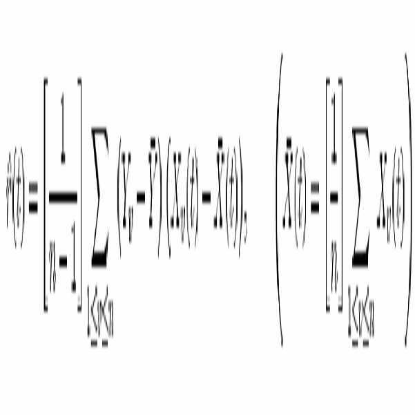
E(estimation)와 함께 임의 값 Y와 X(t)를 센터링(centering)한 후
![]()
수학식6을 고려하기로 한다.
수학식 4를 수학식 1과 수학식 2에 대입하고 수학식 5와 수학식 6을 고려하면, 수학식 7, 수학식 8, 수학식 9를 얻을 수 있다.
![]()
수학식 7과 수학식 8로부터 Y의 추정과 에러추정 ![]()
![]()
수학식 10은 b = b0 값에 대한 응답으로 바이어스가 없는(non biased) 추정인 수학식 1의 성질을 기술한다.
a에 의존하는 수학식 9의 함수로부터 J=J(a)를 고려한다. 이점에 의해, 잘 정의된 에러최소화 함수와 결정된 함수간의 관계를 얻는다. 상술한 바와 같이, 에러추정시스템과 일정한 정의 간의 의존성이 무시되고 피할 수 있다.
3.2 분해(Decomposition)
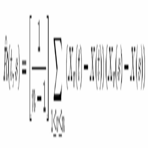
상관과 크로스-상관함수의 정의로부터 수학식 11을 받아들일 수 있다.
![]()
![]()
수학식 9는 수학식 13과 같이 쓸 수 있다.
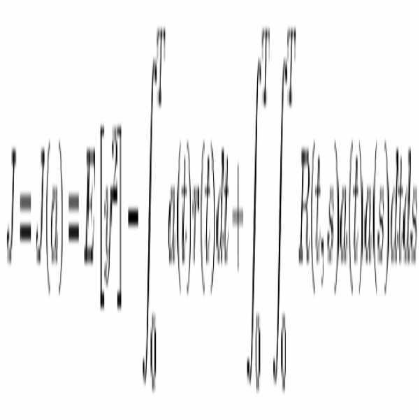
파라미터 a를 결정하기 위해, 함수의 클래스를 고려하여 가중치 함수와 J=J(a)의 효과적인 최소화 알고리즘을 기술하는 것이 필요하다.
가상 기술 영역에서의 다른 과제들처럼 이 문제를 해결하는 근본적인 의미는 [0,T]에서 사적 상관 함수 R(t,s)의 직교 시스템 ![]()
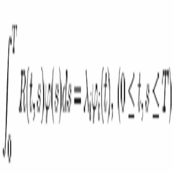
그리고 Karhunen-Loeve 직교 분해는 수학식 15와 같다.

여기서 ![]()
비주기 임의 프로세스는 비상관 임의의 계수를 갖는 푸리에 급수로 표현할 수 없지만 비상관 계수를 갖는 직교함수 ![]()
수학식 15는 [0,T]에서 제곱평균값에서 균일하게 수렴되고 있다. 직교 시스템 ![]()
![]()
시스템 ![]()

여기서![]()
수학식 12와 함께 수학식 15 내지 수학식 17로부터 수학식 18을 얻을 수 있다.

상관관계 R(t,s)의 비 네거티브(non-negative) 결정으로부터 사적인(private) 값(![]()
![]()
수학식 17과 수학식 18은 수학식 15에서 직교 분해 성질을 나타낸다. 임의의 프로세스 x=x(t)가 집중되기 때문에, 수학식 16과 수학식 19로부터 수학식 20을 얻는다.
![]()
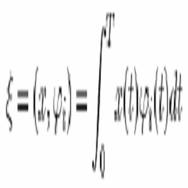
상술한 바와 같이 균일한 형태의 프로세서 X=X(t)를 고려하면, 수학식 16, 수학식 19 및 수학식 20으로부터 수학식 15의 계수 ![]()
![]()
![]()
![]()
3.3 결합 및 중첩
이 시점에서 분해의 최종 결과물을 출력함수의 추정과 에러추정-시스템 질 결정에 대한 최소화 함수-로 나타낼 것이다. m 값을 고정시키고, 수학식 21과 같이 가중 함수(weight function)를 고려하기로 한다.
![]()
수학식 6과 수학식 9로 돌아가 수학식 22를 받아들이고
![]()
수학식 15, 수학식 17 및 수학식 19를 기초로 하여 수학식 23과 수학식 24를 얻을 수 있다.


수학식 21과 수학식 22로부터 만일 i에서 ![]()
![]()
![]()
![]()
![]()
![]()
상기 수학식 25는 수학식 21의 클래스에서 J=J(a)에 대한 최소치를 제공하고, ![]()
수학식 26을 수학식 24에 대입하면 수학식 27을 얻게 된다.
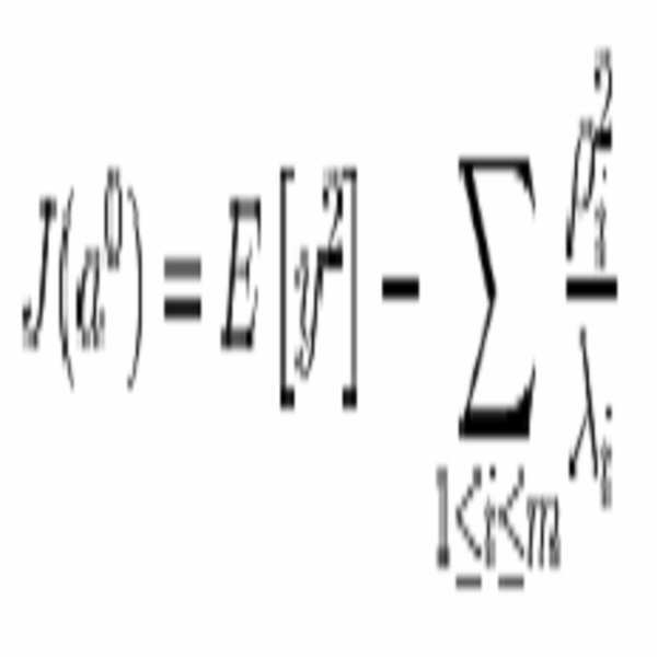
여기서부터 수학식 21에 주목하면, 수학식 28의 결론을 얻게 된다.
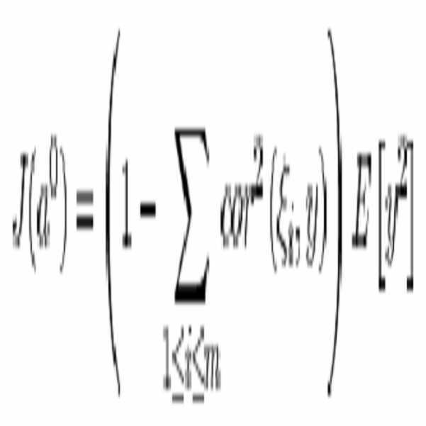
여기서 ![]()
![]()
수학식 23과 수학식 26에 따르면, 수학식 24의 ![]()
![]()

전파 에러 ![]()
![]()
임의값 Y의 특성인 ![]()
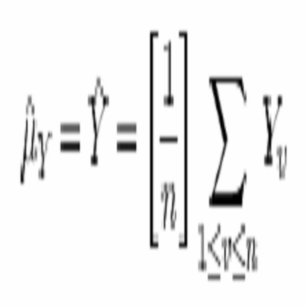
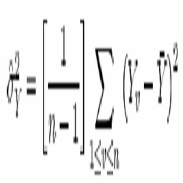
여기서 n은 관찰 번호이고 ![]()
3.4 분석
상술한 수식은 신호시스템(SS)에 기초한 이동장치의 현재위치와 방향의 전파와 추정시스템에 대한 수학적 도구이다.
이 결과는 다 차원 경우로 쉽게 확장될 수 있으며, 추정값의 다양한 파라미터를 고려하여 프로세스의 몇몇 특성의 교차관계(cross-relation)와 교차함수의 분석을 허용한다.
4. 완전한 분해 알고리즘
본 발명에 의한 멀티센서 데이터 퓨전은 다음과 같이 구현될 수 있다. 먼저, 프로세스를 초기화한다. 그 다음에 소스 신호가 흩어지고, 아날로그 및 디지털 접근방법에 따라 Karhunen-Loeve 분해가 수행된다. ![]()
![]()
![]()
상술한 단계들은 퓨전 신호처리와 예측에 대한 클로스-루프(close-loop) 시퀀스를 제공한다.
5. 객체 같은 세미 레벨(object-like semi-level) 정보 퓨전
상술한 바에 따르면, 도 1과 도2에 도시된 바와 같이, 다음과 같은 특성을 갖는 시스템을 구축할 수 있다. 크기가 조절가능하다.(scalable) 이로 인해 어떤 환경조건에서 쉽게 확장되거나 압축될 수 있다. 생존가능하다.(survivable) 따라서 만일 센서 소스의 하나가 없어지거나 오작동하면 전체시스템이 모두 못 쓰게 되지 않고 단지 대표적으로 관련된 에러 추정을 감소시킬 뿐이다. 모듈화 가능하여(modular), 어떤 종류의 센서가 어떤 종류의 센싱에 대해 책임있는지를 쉽게 알 수 있다. 퓨전채널당 에러 추정과 출력 보정이 가능하다. 이로 인해 모든 센서 소스는 다음 레벨의 데이터 퓨전에 대한 그 자신의 비 회귀적 에러 추정과 경고 능력을 갖는다.
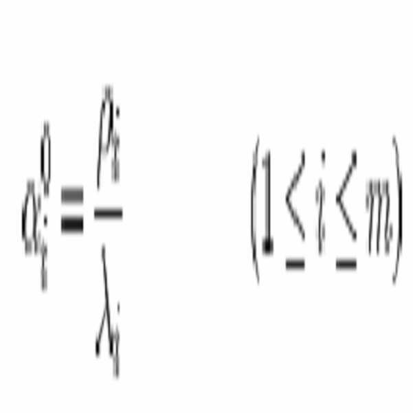
센서퓨징을 이용한 무인 이동체의 위치추정 방법은 다음과 같은 단계로 이루어진다. (1) 로봇의 위치추정을 감지하는 복수의 모델 파라미터를 이용하여 센서 데이터를 동적으로 관측한다. (2) 파라미터 값들을 선택적으로 결합한다. (3) 소정의 신뢰성의 범위에서 상기 파라미터 값들의 변화를 검출한다. (4) 추정과 에러분포를 이용하여, 센서 데이터와 소정의 데이터 변이에 의해 표현되는 무인 이동물체의 위치를 추정한다.
상기 (1)단계에서, 동적으로 관측된 파라미터 값들은 센서로부터의 실시간 정보이다. 상기 센서에 따라, 동일한 동적 모델(모델성분 분해로 표현되는 센서 전달함수)을 구성할 수 있다. 센서 전달함수를 사용하여 어떤 파라이터가 더 중요한지 결정할 수 있다. 이것을 하기 위해, 모든 파라미터 값을 계산하는 것이 필요하다. 이는 각 파라미터 가중 계수를 계산하는 것이다. 가중계수를 계산하기 위해 자동 회귀 분석 절차(auto-regression analysis procedure)을 사용할 수 있다. 수학식 14 내지 수학식 19는 채널(센서) 분해 모델을 나타낸다.
상기 (2)단계에서, 어떤 파라미터가 입력되는지를 결정한다. 센서 퓨젼 방법을 이용한 적절한 계산을 위해 센서 파라미터 모델들 간의 관련성을 결정할 필요가 있다. 이를 위해, 교차상관(cross correlation)을 계산할 필요가 있다. 이는 모델의 자유도와 전체 모델의 다른 파트들 간의 상관도를 결정하는 표준 절차이다. 분석이 되고 나면, 어떤 채널(센서 모델)이 물체의 위치와 에러 추정에 더 효과적인가를 결정할 수 있다.
또한 에러 분포와 그에 상응하는 채널 에러 보상을 분석하기 위해 이 결과들을 사용할 수 있다. 수학식 9, 13,24 및28은 에러 추정을 나타내고, 수학식 14 내지 19는 분해 모델을 나타내고, 수학식 21 내지 24와 27은 에러 추정과 분해 모델 간의 연결을 나타내고 있다.
상기 (3)단계에서, 채널(센서)의 모델들과 이에 상응하는 파라미터들이 적절한 모델 성능을 위해 추적될 필요가 있다. 이를 위해, J(a)를 실시간으로 추적하는 것이 필요하다. 이는 종래기술에 의하면 데이터 방대한 데이터 량과 흐름 때문에 어려운 작업이다. 그러나 본 발명에서는 분해모델을 사용하기 때문에 실시간으로 계산 가능하다. 그래서, 수학식 28을 이용하여 실시간으로 파라미터 값들의 변화량을 추적할 수 있다.
상기 (4)단계에서, 알고리즘에 대한 최종 방정식들, 즉 수학식 28 내지 33은 채널(센서) 모델, 분해모델 및 교차 상관 분석을 한 후에 만들어 질 수 있다. 상기 수학식들은 추정과 에러 분산을 얻기 위한 주된 결과들이다.
한편 도 3은 본 발명의 구성을 블록도로 도시한 것으로서, 센서채널부(300), 교차채널(cross channel) 모델계산/피드백 지원부(320), 추정분해부(estimation decompositon part, 340), 추정중첩부(360) 및 최종결과계산부(380)를 포함하여 이루어진다.
상기 센서채널부(300)는 센서 하드웨어 계층과 그에 상응하는 소프트웨어 계층으로 구성된다. 상기 소프트웨어 계층은 전원부가 있는 센서를 제공하고 제어신호 시퀀스 제공을 담당하고 센서로부터의 가공되지 않은 데이터를 추출하여 전처리 계층에 제공하는 것을 담당한다. 이 시점에서 신호와 관련된 모델이 구성된다. 그러한 모델의 구성방법은 다음과 같다.
(1)FFT를 통해 신호데이터를 프로세싱함으로써 스펙트럼 영역에서 신호를 분석할 수 있다. 첫째, 스펙트럼 함수 형태의 상태를 추적하고 센서채널의 상태를 예측하거나 단지 분석하는 것이 가능하다. 둘째, 최소 평균 제곱 에러 방법(least mean square error method)의 접근에 의해 스펙트럼 함수에서 자동 복귀방법(auto regression method)의 도움으로 다항식을 fit 하는 것이 가능하다. 이 방법의 장점은 신호 관련 모델(signal-related model)의 도움으로 인 프로세스(in-process) 신호 모니터링과 분석을 쉽게 할 수 있다는 것이다. 그래서 진단과 같은 신호채널 프로세싱을 할 수 있다.
(2)신호채널에서 채널 파라미터 블록의 모델을 도입한다. 채널 파라미터에 대한 유연성있는 피드백을 제공하는 블록의 주된 아이디어는 채널 파라미터 튜닝을 지원한다. 왜냐하면 모든 디바이스의 연산 사이클 동안 인 프로세스 또는 적절히 기능하도록 하는 오프라인 튜닝을 수행하는 것이 필요하다. 그래서 만일 채널의 추상적인 모델을 얻는 것이 가능하다면, 그 채널의 키 파라미터를 얻는 것이 가능하다. 그리고 후에 환경조건에 따라 어떤 시간동안 그 채널의 튜닝을 수행하는 것이 가능하다.
상기 교차 채널 모델 계산/피드백 지원부(320)는 퓨전 알고리즘을 통해 프로세싱을 위한 교차곱(cross-product) 계산을 담당한다. 이를 위해, 교차 및 자동 상관 채널과 같이 교차 관련 product가 필요하다. 채널 파라미터를 위한 에러 피드백을 지원하고, 신호처리 방법에 따른 이유로 전체 신호처리 그림 표현을 위한 에러 추정을 얻는 것이 필요하다. 몇 개의 포인트를 규정하는 것이 필요하다. 첫째, 상관 함수계산을 위한 두 종류의 방법이 있다. 하나는 콘볼류션 적분을 거쳐 보통의 가공되지 않는 신호 변환을 통하는 것이다. 그리고 둘째로 스펙트럼 함수와 파워 스펙트럼 함수를 통해서이다. 둘째, 상기 방법은 신호 채널에서 간단한 상관함수 계산 뿐만 아니라 교차 잡음 가중치를 결정하는 것을 제공한다. 신호의 스펙트럼 함수를 분석함으로써, 초기단계에서 환경의 중요 특징(key features)에 관한 정보를 추출할 수 있다. 그래서 상기 교차채널 모델 계산/피드백 지원부(320)에서 교차 관련된 결과와 에러 최소화 피드백 지원과 센서 채널들의 키 주파수를 얻을 수 있다.
상기 추정 분해부(340)는 직교 가중 함수의 선형조합을 만들 수 있다. 신호 키 특성과 상응하는 수학적 배경의 도움으로 추정신호 표현에대한 가중 함수의 세트를 만든다. 에러 추정 방정식도 고려해야 한다. 그러한 방정식으로 센서채널부(300)에서 에러 보상에 대한 적절한 규칙을 얻는다. 다음 파트는 최적신호처리에 대한 추정계산과 최소화 방정식을 고려한다.
상기 추정 중첩부(360)는 분해된 추정의 가중함수의 세트가 분해 가중 계수의 세트와 측정된 신호값에 대한 분산 임의값의 추정의 상응하는 세트로서 중첩된다. 이 점에서 퓨징된 신호 추정의 최종 결과를 얻을 수 있다. 또한 에러 최소화 함수를 추정하는 것이 필요하다.
상기 최종 결과 계산부(380)는 이동 디바이스 위치정보 추출 및 에러 관련 데이터 분석하며, 최종 결과 계산과 관련된 필요한 정보가 추출된다. 이동 디바이스의 위치 및 현재 상태에 따라 키 특징이 추출된다. 상기 방법의 다음 단계는 환경상태의 최종 결과를 간단히 상관시키는 것이다. 그리고 도 4에 도시된 바와 같이, 결과적으로 디바이스의 위치에 관한 스케일링되지 않고(unscaled) 및 조정되지 않은(uncalibrated) 정보를 얻는 것이다.
한편, 이 외에 센서로부터의 신호처리에 대해 다음과 같은 시퀀스를 고려하기로 한다. 도 5에 도시된 바와 같이, 신호를 수신하여 시스템의 가중함수를 통해 신호를 처리한다.(시간 이동(time shift) Ts≤40 ms인 실시간 버퍼) FFT를 통해 신호를 처리하여 신호의 스펙트럼 함수를 얻는다. 스펙트럼 함수 내에서 신호의 질 함수(quality function)를 분석하는 것이 가능하다. 이는 가중 주파수, 스펙트럼 범위, 형태와 타입, 전체시스템의 어떤 파트가 스펙트럼에서의 주파수 부분을 담당하는가를 포함한다. 스펙트럼 함수에 상응하여, 자동 회귀 모델을 얻고 루트 분포 T-R 영역에 의해 스펙트럼 성질을 분석하는 것이 가능하다. 그러한 분포의 타입과 종류는 모델 분해 계층에 관해 말한다. 이러한 분석의 도움으로 전체 시스템의 몇 개의 파라미터 간의 연결성과 관련성을 얻을 수 있다. (예를 들어 차동 로보트 모델에서의 속도와 방향 파라미터 간의 관계) 그러한 자동 회귀 모델을 얻은 후에, 실시간 모니터링과 각 센싱 채널이 진단함으로써 간결하며(compact), 유연한 수학적 소프트웨어 세트를 만들 수 있다.According to the present invention for solving the above technical problem, a method of estimating the position of an unmanned mobile object using sensor fusing, the first step of measuring a predetermined parameter value from at least two sensors that can detect the position estimation of the unmanned mobile object ; A second step of selectively combining and calculating the parameter values; Detecting a change in the range of expected reliability of the parameters; And a fourth step of combining the estimation and the error distribution to obtain the unknown state of the sensor data and the position of the unmanned moving object represented by the desired inference. The first step includes receiving a source signal; Converting to a frequency domain signal using an FFT and calculating a spectral density function; And fitting the polynomial to a signal dependent on the spectrum and the representation, calculating a corresponding correlation function and obtaining a coefficient.
According to the present invention for solving the above technical problem, the position estimation device of the unmanned moving object using the sensor fusing is composed of a software layer corresponding to the sensor hardware layer, the software layer provides a sensor with a power supply and a control signal A sensor channel unit responsible for providing a sequence and responsible for extracting raw data from the sensor and providing the raw data to the preprocessing layer; Fusion algorithms handle cross-computation for processing, perform cross-related products like cross and auto-correlation channels, support error feedback for channel parameters, and error for full signal representation for reasons of signal processing Cross channel model calculation and feedback support for obtaining an estimate; Create a linear combination of orthogonal weighting functions, create a set of weighting functions for estimating signal representations with the help of a signal key characteristic and corresponding mathematical background, and obtain appropriate rules for error compensation in the sensor channel part by considering the error estimation equation. , Estimated decomposition unit; The set of weighted functions of the decomposed estimates is superimposed as a set of decomposition weighted coefficients and a corresponding set of estimates of variance random values for the measured signal values to obtain the final result of the fused signal estimates and to estimate the error minimization function. Estimated overlap; And extract necessary information related to the final result calculation, key features are extracted according to the position and current state of the mobile device decision, simply correlate the final result of the environmental state, and consequently unscaled and unadjusted with respect to the position of the device. And a final result calculation unit for obtaining the uninformed information. The sensor channel unit analyzes a signal in a spectral region by processing signal data through an FFT. The sensor channel unit tracks states in the form of spectral functions, predicts or merely analyzes the state of the sensor channels, obtains polynomials with the aid of an automatic return method from the spectral functions by means of least mean square error methods, and performs signal channel processing such as diagnostics. It obtains an abstract model of a channel, obtains key parameters of the channel, and then performs tuning of the channel for a predetermined time according to environmental conditions. The cross-channel model calculation and feedback support need to define several points, and two kinds of methods for calculating the correlation function, through the convolution integration, through the normal raw signal conversion and the spectral function and There is a way through the power spectral function, the latter provides for determining the cross-noise weight as well as simple correlation function calculations in the signal channel, and it is necessary to analyze the spectral function of the signal, and information about the important aspects of the environment at an early stage. In the second part of the fusion structure, cross-related results and error minimization feedback support and key frequencies of the sensor channels are obtained.
A computer readable recording medium having recorded thereon a program for executing the invention described above is provided.
Hereinafter, the present invention will be described in detail.
1. Introduction
The present invention provides a new form of technology for sensor data fusion in accordance with an object-like layered structure approach. The technique is based on an approximation of nonlinear deformations obtained by multidimensional extension of Karhunen-Loewe decomposition. Conceptually, the principle behind this approach is different from conventional filter techniques. Thanks to the decomposition method, no derivatives for the interpolation formula are needed. Even predefined equations are not necessary. This is due to the principle of auto-regression polynomial fitting based on spectral functions calculated from sensor signals. Of course, it is necessary to limit the upper limit on the order of the polynomial. Although the implementation is as complex as a filter based on Taylor approximation, the computational burden will be much smaller. Also, assuming that the estimation error is distributed, the new fusing scheme provides and is more accurate in the error calculation. Due to the deep feedback based minimization to the entry point of the fusing scheme according to the invention, error estimation is possible with higher accuracy than other filtering techniques (including Taylor approximation).
2. General Approach
The decomposition method for signal processing and its advantages will be described. One common method of signal processing is to represent a signal as a set of well-defined periodic functions with coefficients. The great advantage of this method is that the signal can be easily described by the quantity and query parameters. It is also well known that by this method the signal can be examined by representing it in the spectrum in the frequency domain.
In the present invention, the representation of the frequency domain of the signal shows a general picture of key frequencies and sensor channels. Analyzing the most widely used structure in SensorFusion technology shows that no method or structure is used to pre-analyze the signal. Although such technology is widely applied in industrial applications, it is not often applied in the application of mobile robots. Since the source quality is analyzed, the feasibility of the current method (signal representation) is well known. Through source analysis, it is possible to monitor and diagnose channel state prediction techniques.
According to the problems of SLAM (Simultaneous Localization and Mapping) or Self Navigation technology, the main disturbance and serious error part of the recognition system of the robot system is sensor signal processing and consequently sensor data fusion. However, if the signal is lost or disturbed by noise, the input to the sensor data fusion part will be disturbed, and thus the output of the sensor data fusion part will be disturbed in making the decision and at the end of the data processing. Wrong location and direction information will follow. This requires technology that makes it easy to implement and assure the monitoring and diagnostics of the source signal. Therefore, a combined and hybrid sensor data fusion method has been proposed.
In the present invention, there are several layers for the source signal being processed in real time, followed by fusion. For clarity of understanding, the method according to the present invention will be described.
The following general structure for the preprocessing of the source signal is proposed.
(1) receiving a source signal,
(2) The FFT is used to convert the source signal into a frequency domain signal.
(3) Calculate the spectral density function.
(4) Fit polynomials into spectral and signal-dependent representations (analyze signal processing-channel stability and quality).
(5) Compute the corresponding correlation function and find the coefficient. Processed through the decomposition method corresponding to the kernel of the present invention. Compute prediction and error estimation models.
Each step of the above-described method will be described. First, a representative polynomial representing the spectral function is obtained. Second, it is possible to analyze the signal quality through the root distribution of the polynomial in the TR region using the polynomial. This method is very useful when it is often necessary to obtain a conversion function that allows us to describe the state and condition of a process (the representative signal of the process). It is then possible to obtain the keying frequency (the main and characteristic frequency of the process) and analyze which parts of the hardware influence the signal processing.
Third, the calculation of the correlation function can be handled in two ways. 1) From source and raw signal-this method provides the original appearance of the source. 2) From the Spectrum Function-This method gives a correlation in terms of the frequency domain.
Several key points will be reviewed in the mathematical context of the present invention.
3. Method Definition and Description
The key points of the present invention are defined. For the sake of simplicity, consider the one-dimensional case. This method can be easily extended to n dimensions. The amount of independent channels is assumed by the meaning of dimension.
The basic idea of the present invention is to provide an algorithm that represents an observable process, such as a stochastic process, within well defined constraints. The main principle of the present invention is to decompose aperiodic random processes into orthogonal functions with uncorrelated coefficients. At the same time, an error minimization method is implemented during the decomposition to the orthogonal function. This type of error estimation provides a robust technique for cross channel and in channel noise and error reduction. And eventually the result of the method can be easily used for the necessary information extract. Additional properties for data analysis make it possible to outline the spectral functions described above. Review the method step by step.
Estimation definition
Consider the definition of the source signal as a time-related function. In the present invention, it is necessary to distinguish the result functions which clearly and firmly describe environmental states. Statistical Estimation of Signaling System (SS) ![]()
![]()
![]()
Consider one-dimensional case (p = q = 1). We will look at the aspects of building and applying linear estimates.
here ![]()
![]()
![]()
![]()
Set of arbitrary values Y, X (t), t∈ ![]()
![]()
According to this, the weight function a usually belongs to the function class of t∈ [0, T]. This kind of function can be chosen from deductive decisions or a set of arbitrary values ![]()
If L 2 [0, T] is fixed, equation (2) becomes as shown in equation (3).
![]()
From
After centering the random values Y and X (t) with E (estimation)
![]()
Equation 6 will be considered.
Substituting Equation 4 into
![]()
Estimate and Error Estimation of Y from Equations 7 and 8 ![]()
![]()
Equation 10 describes the property of
Consider J = J (a) from the function of equation 9 which depends on a. By this, we get a well-defined relationship between the error minimization function and the determined function. As mentioned above, dependencies between the error estimation system and certain definitions can be ignored and avoided.
3.2 Decomposition
Equation 11 can be taken from the definition of correlation and cross-correlation function.
![]()
![]()
Equation 9 may be written as Equation 13.
To determine the parameter a, it is necessary to describe the weighting function and the effective minimization algorithm of J = J (a), taking into account the class of the function.
Like other challenges in the field of virtual technology, the fundamental meaning of solving this problem is the orthogonal system of the private correlation function R (t, s) at [0, T]. ![]()
And Karhunen-Loeve orthogonal decomposition is as shown in equation (15).
here ![]()
An aperiodic random process cannot be represented as a Fourier series with uncorrelated arbitrary coefficients but an orthogonal function with uncorrelated coefficients ![]()
Equation 15 is uniformly converged at the root mean square value in [0, T]. Orthogonal system ![]()
![]()
system ![]()
here ![]()
Equation 18 can be obtained from Equations 15 to 17 together with Equation 12.
The private value from the non-negative decision of the correlation R (t, s) ![]()
![]()
(17) and (18) represent orthogonal decomposition properties in (15). Since any process x = x (t) is concentrated, equation (20) is obtained from equations (16) and (19).
![]()
In consideration of the processor X = X (t) having a uniform form as described above, the coefficients of the equations (15) to (16), (19) and (20) ![]()
![]()
![]()
![]()
3.3 Joining and Nesting
At this point, the final output of the decomposition will be expressed as an estimate of the output function and an error estimate-a minimization function for system quality decisions. The value of m is fixed and a weight function will be considered as shown in Equation 21.
![]()
Go back to equations 6 and 9, accept equation 22,
![]()
Based on Equations 15, 17 and 19, Equations 23 and 24 can be obtained.
From equation 21 and equation 22 if i ![]()
![]()
![]()
![]()
![]()
![]()
Equation 25 provides a minimum value for J = J (a) in the class of Equation 21, ![]()
Substituting Equation 26 into Equation 24 yields Equation 27.
If attention is paid to Equation 21 from this point, the conclusion of Equation 28 is obtained.
here ![]()
![]()
According to Equation 23 and Equation 26, ![]()
![]()
Propagation error ![]()
![]()
Is a property of random value Y ![]()
Where n is the observation number ![]()
3.4 Analysis
The above-described equation is a mathematical tool for the propagation and estimation system of the current position and direction of the mobile device based on the signal system SS.
This result can be easily extended to multidimensional cases and allows for cross-relation and analysis of cross-functions of several features of the process, taking into account the various parameters of the estimates.
4. Complete Decomposition Algorithm
Multi-sensor data fusion according to the present invention can be implemented as follows. First, initialize the process. The source signal is then scattered and Karhunen-Loeve decomposition is performed according to the analog and digital approaches. ![]()
![]()
![]()
The above steps provide a close-loop sequence for fusion signal processing and prediction.
5. Fusion of object-like semi-level information
As described above, as illustrated in FIGS. 1 and 2, a system having the following characteristics can be constructed. It is scalable, allowing it to be easily expanded or compressed under certain environmental conditions. Survivable Therefore, if one of the sensor sources is missing or malfunctions, the entire system will not be exhausted and only a representative reduction in the associated error estimates is possible. Modular, it is easy to see what kind of sensor is responsible for what kind of sensing. Error estimation and output correction per fusion channel are possible. This allows all sensor sources to have their own non-regressive error estimation and warning capabilities for the next level of data fusion.
The method for estimating the position of the unmanned moving object using the sensor fusing consists of the following steps. (1) The sensor data is dynamically observed using a plurality of model parameters that detect the position estimation of the robot. (2) Selectively combine parameter values. (3) Detect changes in the parameter values within a range of predetermined reliability. (4) Using the estimation and the error distribution, the position of the unmanned moving object represented by the sensor data and the predetermined data variation is estimated.
In step (1), the dynamically observed parameter values are real time information from the sensor. Depending on the sensor, the same dynamic model (sensor transfer function expressed by model component decomposition) can be constructed. Sensor transfer functions can be used to determine which parameters are more important. To do this, it is necessary to calculate all parameter values. This is to calculate each parameter weighting factor. An auto-regression analysis procedure can be used to calculate weighting factors. Equations 14 to 19 represent channel (sensor) decomposition models.
In step (2), it is determined which parameter is input. It is necessary to determine the association between sensor parameter models for proper calculation using the sensor fusion method. To do this, it is necessary to calculate cross correlation. This is a standard procedure to determine the degree of freedom of a model and the correlation between other parts of the model. Once analyzed, it is possible to determine which channel (sensor model) is more effective at estimating the position and error of the object.
You can also use these results to analyze the error distribution and corresponding channel error compensation. Equations 9, 13, 24 and 28 represent error estimation, Equations 14 to 19 represent decomposition models, and Equations 21 to 24 and 27 represent the connection between the error estimation and the decomposition model.
In step (3), the models of the channel (sensor) and corresponding parameters need to be tracked for proper model performance. For this purpose, it is necessary to track J (a) in real time. This is a difficult task according to the prior art because of the huge amount of data and the flow of data. However, in the present invention, since the decomposition model is used, it can be calculated in real time. Thus, the change amount of the parameter values can be tracked in real time using Equation 28.
In the step (4), the final equations for the algorithm, that is, the equations (28) to (33) can be made after the channel (sensor) model, decomposition model and cross correlation analysis. The above equations are the main results for obtaining estimation and error variance.
3 is a block diagram illustrating a configuration of the present invention, wherein the
The
(1) The signal can be analyzed in the spectral region by processing the signal data through the FFT. First, it is possible to track the state in the form of a spectral function and to predict or only analyze the state of the sensor channel. Second, it is possible to fit a polynomial with the help of the auto regression method in the spectral function by the approach of the least mean square error method. The advantage of this method is that it is easy to monitor and analyze in-process signals with the help of signal-related models. So you can do signal channel processing like diagnosis.
(2) Introduce the model of the channel parameter block in the signal channel. The main idea of a block that provides flexible feedback on channel parameters is to support channel parameter tuning. This is because it is necessary to perform in-process or offline tuning to function properly during the computation cycle of all devices. So if it is possible to get an abstract model of a channel, it is possible to get the key parameters of that channel. Then it is possible to perform tuning of the channel for some time depending on the environmental conditions.
The cross channel model calculation /
The
The
The
Meanwhile, in addition to the signal processing from the sensor, the following sequence will be considered. As shown in FIG. 5, the signal is received and processed through a weighting function of the system (a real time buffer having a time shift of Ts ≦ 40 ms). Get It is possible to analyze the quality function of the signal within the spectral function. This includes weighted frequencies, spectral ranges, types and types, and which parts of the overall system are responsible for the frequency portion of the spectrum. Corresponding to the spectral function, it is possible to obtain an autoregressive model and analyze the spectral properties by the root distribution TR region. The type and type of such distribution speaks about the model decomposition hierarchy. With the help of this analysis, the connectivity and relevance between several parameters of the overall system can be obtained. After obtaining such an automatic regression model, a real-time monitoring and diagnosis by each sensing channel can be made compact and a flexible set of mathematical software.
삭제delete
삭제delete
삭제delete
삭제delete
삭제delete
삭제delete
삭제delete
삭제delete
삭제delete
삭제delete
삭제delete
삭제delete
삭제delete
삭제delete
삭제delete
삭제delete
삭제delete
삭제delete
삭제delete
삭제delete
삭제delete
삭제delete
삭제delete
삭제delete
삭제delete
삭제delete
삭제delete
삭제delete
삭제delete
삭제delete
삭제delete
삭제delete
삭제delete
삭제delete
삭제delete
삭제delete
삭제delete
삭제delete
삭제delete
삭제delete
삭제delete
삭제delete
삭제delete
삭제delete
삭제delete
삭제delete
삭제delete
삭제delete
삭제delete
삭제delete
삭제delete
삭제delete
삭제delete
삭제delete
삭제delete
삭제delete
삭제delete
삭제delete
삭제delete
삭제delete
삭제delete
삭제delete
삭제delete
삭제delete
삭제delete
삭제delete
삭제delete
삭제delete
삭제delete
삭제delete
삭제delete
삭제delete
삭제delete
삭제delete
삭제delete
삭제delete
삭제delete
삭제delete
삭제delete
삭제delete
삭제delete
삭제delete
삭제delete
삭제delete
삭제delete
삭제delete
삭제delete
삭제delete
삭제delete
삭제delete
삭제delete
삭제delete
삭제delete
삭제delete
삭제delete
삭제delete
삭제delete
삭제delete
삭제delete
삭제delete
삭제delete
삭제delete
삭제delete
삭제delete
삭제delete
삭제delete
삭제delete
삭제delete
삭제delete
본 발명에 의하면, 크기가 조절가능하여(scalable) 어떤 환경조건에서 쉽게 확장되거나 압축될 수 있다. 그리고 생존가능하여(survivable), 만일 센서 소스의 하나가 없어지거나 오작동하면 전체시스템이 모두 못 쓰게 되지 않고 단지 지수적으로 관련된 에러 추정을 감소시킬 뿐이다. 또한 모듈화 가능하여(modular), 어떤 종류의 센서가 어떤 종류의 센싱에 대해 책임있는지를 쉽게 알 수 있다. 또한 퓨전채널당 에러 추정과 출력 보정이 가능하다. 따라서 모든 센서 소스는 다음 레벨의 데이터 퓨전에 대한 그 자신의 비 회귀적 에러 추정과 경고 능력을 갖는다.According to the invention, it is scalable in size and can be easily expanded or compressed under certain environmental conditions. And survivable, if one of the sensor sources goes missing or malfunctions, the entire system is not all worn down and only reduces the exponentially associated error estimate. It is also modular, making it easy to see what kind of sensor is responsible for what kind of sensing. Error estimation and output correction per fusion channel are also possible. Thus every sensor source has its own non-regressive error estimation and warning capabilities for the next level of data fusion.
Claims (7)
Priority Applications (4)
| Application Number | Priority Date | Filing Date | Title |
|---|---|---|---|
| KR1020030068073A KR100707168B1 (en) | 2003-09-30 | 2003-09-30 | Method and device for position estimation of unmanned moving object using sensor fusing |
| CNA2004100995016A CN1645283A (en) | 2003-09-30 | 2004-09-24 | Method and device for estimating position of unmanned mobile body by use of sensor fusing |
| US10/951,908 US20070233336A1 (en) | 2003-09-30 | 2004-09-29 | Method and apparatus for navigating unmanned vehicle using sensor fusion |
| JP2004288232A JP2005108246A (en) | 2003-09-30 | 2004-09-30 | A method for estimating the position of an unmanned moving body using sensor fusing, a device thereof, and a computer-readable recording medium on which a program is recorded. |
Applications Claiming Priority (1)
| Application Number | Priority Date | Filing Date | Title |
|---|---|---|---|
| KR1020030068073A KR100707168B1 (en) | 2003-09-30 | 2003-09-30 | Method and device for position estimation of unmanned moving object using sensor fusing |
Publications (2)
| Publication Number | Publication Date |
|---|---|
| KR20050031809A KR20050031809A (en) | 2005-04-06 |
| KR100707168B1 true KR100707168B1 (en) | 2007-04-13 |
Family
ID=34545534
Family Applications (1)
| Application Number | Title | Priority Date | Filing Date |
|---|---|---|---|
| KR1020030068073A Expired - Fee Related KR100707168B1 (en) | 2003-09-30 | 2003-09-30 | Method and device for position estimation of unmanned moving object using sensor fusing |
Country Status (4)
| Country | Link |
|---|---|
| US (1) | US20070233336A1 (en) |
| JP (1) | JP2005108246A (en) |
| KR (1) | KR100707168B1 (en) |
| CN (1) | CN1645283A (en) |
Families Citing this family (40)
| Publication number | Priority date | Publication date | Assignee | Title |
|---|---|---|---|---|
| AU2004294651A1 (en) * | 2003-10-21 | 2005-06-16 | Proxy Aviation Systems, Inc. | Methods and apparatus for unmanned vehicle control |
| US7395156B2 (en) * | 2005-06-23 | 2008-07-01 | Raytheon Company | System and method for geo-registration with global positioning and inertial navigation |
| US7840287B2 (en) * | 2006-04-13 | 2010-11-23 | Fisher-Rosemount Systems, Inc. | Robust process model identification in model based control techniques |
| DE102007029299B4 (en) * | 2007-06-22 | 2011-12-22 | Fraba Ag | Optical sensor for positioning tasks |
| US20090240390A1 (en) * | 2008-03-21 | 2009-09-24 | Nenad Nenadic | System and method for component monitoring |
| GB0911331D0 (en) * | 2009-06-30 | 2009-08-12 | Univ Aston | Characterising properties or behaviour of biological cells |
| JP5776332B2 (en) * | 2011-05-27 | 2015-09-09 | 富士通株式会社 | Map processing method and program, and robot system |
| CN103162678B (en) * | 2013-03-11 | 2015-05-13 | 哈尔滨工业大学 | Batch MEMS gyro information fusion method |
| US10257729B2 (en) | 2013-03-15 | 2019-04-09 | DGS Global Systems, Inc. | Systems, methods, and devices having databases for electronic spectrum management |
| US10257728B2 (en) | 2013-03-15 | 2019-04-09 | DGS Global Systems, Inc. | Systems, methods, and devices for electronic spectrum management |
| US9622041B2 (en) | 2013-03-15 | 2017-04-11 | DGS Global Systems, Inc. | Systems, methods, and devices for electronic spectrum management |
| US11646918B2 (en) | 2013-03-15 | 2023-05-09 | Digital Global Systems, Inc. | Systems, methods, and devices for electronic spectrum management for identifying open space |
| US10219163B2 (en) | 2013-03-15 | 2019-02-26 | DGS Global Systems, Inc. | Systems, methods, and devices for electronic spectrum management |
| US10257727B2 (en) | 2013-03-15 | 2019-04-09 | DGS Global Systems, Inc. | Systems methods, and devices having databases and automated reports for electronic spectrum management |
| US10237770B2 (en) | 2013-03-15 | 2019-03-19 | DGS Global Systems, Inc. | Systems, methods, and devices having databases and automated reports for electronic spectrum management |
| US12356206B2 (en) | 2013-03-15 | 2025-07-08 | Digital Global Systems, Inc. | Systems and methods for automated financial settlements for dynamic spectrum sharing |
| US12256233B2 (en) | 2013-03-15 | 2025-03-18 | Digital Global Systems, Inc. | Systems and methods for automated financial settlements for dynamic spectrum sharing |
| US10244504B2 (en) | 2013-03-15 | 2019-03-26 | DGS Global Systems, Inc. | Systems, methods, and devices for geolocation with deployable large scale arrays |
| US10299149B2 (en) | 2013-03-15 | 2019-05-21 | DGS Global Systems, Inc. | Systems, methods, and devices for electronic spectrum management |
| US10271233B2 (en) | 2013-03-15 | 2019-04-23 | DGS Global Systems, Inc. | Systems, methods, and devices for automatic signal detection with temporal feature extraction within a spectrum |
| US10231206B2 (en) | 2013-03-15 | 2019-03-12 | DGS Global Systems, Inc. | Systems, methods, and devices for electronic spectrum management for identifying signal-emitting devices |
| US9037403B2 (en) * | 2013-03-26 | 2015-05-19 | Toyota Motor Engineering & Manufacturing North America, Inc. | Intensity map-based localization with adaptive thresholding |
| WO2015126486A1 (en) | 2013-11-18 | 2015-08-27 | Bae Systems Information And Electronic Systems Integration Inc. | Process for tunnelized cyclostationary to achieve low-energy spectrum sensing |
| JP6240595B2 (en) * | 2014-12-10 | 2017-11-29 | 株式会社豊田中央研究所 | Self-position estimation apparatus and mobile body equipped with self-position estimation apparatus |
| US9581449B1 (en) * | 2015-01-26 | 2017-02-28 | George W. Batten, Jr. | Floor patterns for navigation corrections |
| US9802620B2 (en) * | 2015-12-18 | 2017-10-31 | GM Global Technology Operations LLC | Position error estimate and implementation for autonomous driving |
| WO2018063444A1 (en) | 2016-09-27 | 2018-04-05 | Bae Systems Information And Electronic Systems Integration Inc. | Techniques for implementing a portable spectrum analyzer |
| US10498951B2 (en) | 2017-01-23 | 2019-12-03 | Digital Global Systems, Inc. | Systems, methods, and devices for unmanned vehicle detection |
| US10459020B2 (en) | 2017-01-23 | 2019-10-29 | DGS Global Systems, Inc. | Systems, methods, and devices for automatic signal detection based on power distribution by frequency over time within a spectrum |
| US10700794B2 (en) | 2017-01-23 | 2020-06-30 | Digital Global Systems, Inc. | Systems, methods, and devices for automatic signal detection based on power distribution by frequency over time within an electromagnetic spectrum |
| US10529241B2 (en) | 2017-01-23 | 2020-01-07 | Digital Global Systems, Inc. | Unmanned vehicle recognition and threat management |
| US12205477B2 (en) | 2017-01-23 | 2025-01-21 | Digital Global Systems, Inc. | Unmanned vehicle recognition and threat management |
| US12183213B1 (en) | 2017-01-23 | 2024-12-31 | Digital Global Systems, Inc. | Unmanned vehicle recognition and threat management |
| KR102463176B1 (en) | 2017-10-16 | 2022-11-04 | 삼성전자주식회사 | Device and method to estimate position |
| US10943461B2 (en) | 2018-08-24 | 2021-03-09 | Digital Global Systems, Inc. | Systems, methods, and devices for automatic signal detection based on power distribution by frequency over time |
| CN111324172B (en) * | 2018-12-13 | 2021-11-23 | 北京小米松果电子有限公司 | Remote rod calibration method and device, electronic equipment and storage medium |
| CN112598019B (en) * | 2020-10-28 | 2024-04-02 | 南京航空航天大学 | Heterogeneous vibration signal space-time multi-cross-correlation analysis and self-adaptive weighted fusion method |
| CN114894189B (en) * | 2022-02-18 | 2025-04-08 | 北京理工大学 | Hierarchical multi-layer multi-source fusion instant access navigation method and system |
| CN118584865B (en) * | 2024-05-29 | 2024-11-22 | 京彩未来智能科技股份有限公司 | Industrial park data integration and analysis system based on cloud computing |
| CN118980381B (en) * | 2024-10-16 | 2024-12-17 | 昆明理工大学 | Communication interference-oriented multi-robot co-location method, processor and medium |
Citations (1)
| Publication number | Priority date | Publication date | Assignee | Title |
|---|---|---|---|---|
| JP2001083232A (en) * | 1999-08-16 | 2001-03-30 | Raytheon Co | Passive target positioning device |
-
2003
- 2003-09-30 KR KR1020030068073A patent/KR100707168B1/en not_active Expired - Fee Related
-
2004
- 2004-09-24 CN CNA2004100995016A patent/CN1645283A/en active Pending
- 2004-09-29 US US10/951,908 patent/US20070233336A1/en not_active Abandoned
- 2004-09-30 JP JP2004288232A patent/JP2005108246A/en active Pending
Patent Citations (1)
| Publication number | Priority date | Publication date | Assignee | Title |
|---|---|---|---|---|
| JP2001083232A (en) * | 1999-08-16 | 2001-03-30 | Raytheon Co | Passive target positioning device |
Also Published As
| Publication number | Publication date |
|---|---|
| KR20050031809A (en) | 2005-04-06 |
| US20070233336A1 (en) | 2007-10-04 |
| JP2005108246A (en) | 2005-04-21 |
| CN1645283A (en) | 2005-07-27 |
Similar Documents
| Publication | Publication Date | Title |
|---|---|---|
| KR100707168B1 (en) | Method and device for position estimation of unmanned moving object using sensor fusing | |
| JP7461440B2 (en) | COMPUTER SYSTEM AND METHOD FOR PERFORMING ROOT CAUSE ANALYSIS AND BUILDING PREDICTION MODELS FOR THE OCCURRENCE OF RARE EVENTS IN PLANT-WIDE OPERATIONS - Patent application | |
| Lindemann et al. | Anomaly detection and prediction in discrete manufacturing based on cooperative LSTM networks | |
| CN104166787B (en) | A kind of aero-engine method for predicting residual useful life based on multistage information fusion | |
| JP6609050B2 (en) | Anomalous fusion in temporal causal graphs | |
| US8725456B1 (en) | Decomposition technique for remaining useful life prediction | |
| JP6068468B2 (en) | A sequential kernel regression modeling method for prediction and prediction | |
| CN105095918B (en) | A kind of multi-robot system method for diagnosing faults | |
| JP2020522800A (en) | Computer system and method for online construction and deployment of predictive inference models | |
| JP2014524094A (en) | Monitoring system using kernel regression modeling with pattern sequences | |
| CN101436057A (en) | Numerical control machining tool heat error Bayes network compensation method | |
| WO2018037388A1 (en) | Method and system for performing real-time analytics on a plurality of data streams | |
| De Vita et al. | A novel data collection framework for telemetry and anomaly detection in industrial iot systems | |
| CN114898202B (en) | Scale-space discriminative tracking method for underwater video targets based on multi-model fusion | |
| Dervilis et al. | Robust methods for outlier detection and regression for SHM applications | |
| JP3718765B2 (en) | Plant diagnostic equipment | |
| CN120611266A (en) | A key component failure prediction method and system based on multi-source data fusion | |
| CN117195969A (en) | A ship trajectory prediction method | |
| Velasco-Gallego et al. | Analysis of variational autoencoders for imputing missing values from sensor data of marine systems | |
| Wang et al. | Interval analysis for neural networks with application to fault detection | |
| CN120704282A (en) | An online status monitoring and fault diagnosis system for machinery and equipment | |
| CN118731571B (en) | Communication cable fault detection method and system | |
| Liu et al. | A causal based method for denoising non-homologous noises in time series manufacturing monitoring data | |
| CN112836582A (en) | On-line detection of structural change points in high-dimensional flow systems based on dynamic sparse subspaces | |
| Perry | Identifying the time of polynomial drift in the mean of autocorrelated processes |
Legal Events
| Date | Code | Title | Description |
|---|---|---|---|
| PA0109 | Patent application |
St.27 status event code: A-0-1-A10-A12-nap-PA0109 |
|
| R18-X000 | Changes to party contact information recorded |
St.27 status event code: A-3-3-R10-R18-oth-X000 |
|
| PG1501 | Laying open of application |
St.27 status event code: A-1-1-Q10-Q12-nap-PG1501 |
|
| A201 | Request for examination | ||
| PA0201 | Request for examination |
St.27 status event code: A-1-2-D10-D11-exm-PA0201 |
|
| R17-X000 | Change to representative recorded |
St.27 status event code: A-3-3-R10-R17-oth-X000 |
|
| PN2301 | Change of applicant |
St.27 status event code: A-3-3-R10-R13-asn-PN2301 St.27 status event code: A-3-3-R10-R11-asn-PN2301 |
|
| PN2301 | Change of applicant |
St.27 status event code: A-3-3-R10-R13-asn-PN2301 St.27 status event code: A-3-3-R10-R11-asn-PN2301 |
|
| D13-X000 | Search requested |
St.27 status event code: A-1-2-D10-D13-srh-X000 |
|
| D14-X000 | Search report completed |
St.27 status event code: A-1-2-D10-D14-srh-X000 |
|
| E902 | Notification of reason for refusal | ||
| PE0902 | Notice of grounds for rejection |
St.27 status event code: A-1-2-D10-D21-exm-PE0902 |
|
| T11-X000 | Administrative time limit extension requested |
St.27 status event code: U-3-3-T10-T11-oth-X000 |
|
| P11-X000 | Amendment of application requested |
St.27 status event code: A-2-2-P10-P11-nap-X000 |
|
| P13-X000 | Application amended |
St.27 status event code: A-2-2-P10-P13-nap-X000 |
|
| E701 | Decision to grant or registration of patent right | ||
| PE0701 | Decision of registration |
St.27 status event code: A-1-2-D10-D22-exm-PE0701 |
|
| GRNT | Written decision to grant | ||
| PR0701 | Registration of establishment |
St.27 status event code: A-2-4-F10-F11-exm-PR0701 |
|
| PR1002 | Payment of registration fee |
St.27 status event code: A-2-2-U10-U11-oth-PR1002 Fee payment year number: 1 |
|
| PG1601 | Publication of registration |
St.27 status event code: A-4-4-Q10-Q13-nap-PG1601 |
|
| LAPS | Lapse due to unpaid annual fee | ||
| PC1903 | Unpaid annual fee |
St.27 status event code: A-4-4-U10-U13-oth-PC1903 Not in force date: 20100407 Payment event data comment text: Termination Category : DEFAULT_OF_REGISTRATION_FEE |
|
| PC1903 | Unpaid annual fee |
St.27 status event code: N-4-6-H10-H13-oth-PC1903 Ip right cessation event data comment text: Termination Category : DEFAULT_OF_REGISTRATION_FEE Not in force date: 20100407 |
|
| R18-X000 | Changes to party contact information recorded |
St.27 status event code: A-5-5-R10-R18-oth-X000 |
|
| P22-X000 | Classification modified |
St.27 status event code: A-4-4-P10-P22-nap-X000 |
|
| P22-X000 | Classification modified |
St.27 status event code: A-4-4-P10-P22-nap-X000 |