KR100703382B1 - Apparatus and method for transmitting control information in mobile communication system - Google Patents
Apparatus and method for transmitting control information in mobile communication system Download PDFInfo
- Publication number
- KR100703382B1 KR100703382B1 KR20040009401A KR20040009401A KR100703382B1 KR 100703382 B1 KR100703382 B1 KR 100703382B1 KR 20040009401 A KR20040009401 A KR 20040009401A KR 20040009401 A KR20040009401 A KR 20040009401A KR 100703382 B1 KR100703382 B1 KR 100703382B1
- Authority
- KR
- South Korea
- Prior art keywords
- data
- pilot
- received
- error
- pilot signal
- Prior art date
- Legal status (The legal status is an assumption and is not a legal conclusion. Google has not performed a legal analysis and makes no representation as to the accuracy of the status listed.)
- Expired - Fee Related
Links
Images


Classifications
-
- H—ELECTRICITY
- H04—ELECTRIC COMMUNICATION TECHNIQUE
- H04L—TRANSMISSION OF DIGITAL INFORMATION, e.g. TELEGRAPHIC COMMUNICATION
- H04L1/00—Arrangements for detecting or preventing errors in the information received
- H04L1/12—Arrangements for detecting or preventing errors in the information received by using return channel
- H04L1/16—Arrangements for detecting or preventing errors in the information received by using return channel in which the return channel carries supervisory signals, e.g. repetition request signals
- H04L1/1607—Details of the supervisory signal
- H04L1/1671—Details of the supervisory signal the supervisory signal being transmitted together with control information
-
- H—ELECTRICITY
- H04—ELECTRIC COMMUNICATION TECHNIQUE
- H04L—TRANSMISSION OF DIGITAL INFORMATION, e.g. TELEGRAPHIC COMMUNICATION
- H04L69/00—Network arrangements, protocols or services independent of the application payload and not provided for in the other groups of this subclass
Landscapes
- Engineering & Computer Science (AREA)
- Computer Networks & Wireless Communication (AREA)
- Signal Processing (AREA)
- Computer Security & Cryptography (AREA)
- Mobile Radio Communication Systems (AREA)
- Detection And Prevention Of Errors In Transmission (AREA)
Abstract
본 발명은 이동통신 시스템에서 제어 정보의 전송 장치 및 방법에 대한 것이다. 이동통신 시스템에서, 데이터의 수신 여부와 수신한 데이터의 오류 발생 여부에 따라 미리 결정된 서로 다른 파일럿 패턴들 중 하나를 갖는 파일럿 신호를 선택하고, 상기 선택한 파일럿 신호를 상기 제어 정보로서 전용 물리채널 프레임의 파일럿 필드에 삽입하여 전송한다. 상기 파일럿 패턴들은 상호간에 직교하며, 상기 데이터를 수신하지 못한 경우에 선택되는 제1 파일럿 패턴은 상기 제어 정보를 전송하지 않을 시의 파일럿 패턴과 동일하고, 상기 오류 발생 여부에 따라 선택되는 제2 파일럿 패턴들은 상기 제1 파일럿 패턴과 직교할 뿐 아니라 상호간에 직교한다.The present invention relates to an apparatus and method for transmitting control information in a mobile communication system. In a mobile communication system, a pilot signal having one of different pilot patterns predetermined according to whether data is received and an error in the received data is selected, and the selected pilot signal is used as the control information. Insert into the pilot field and send. The pilot patterns are orthogonal to each other, and a first pilot pattern selected when the data is not received is the same as a pilot pattern when no control information is transmitted, and a second pilot selected according to whether an error occurs. The patterns are not only orthogonal to the first pilot pattern but also orthogonal to each other.
하향링크, 상향링크, 파일럿 신호, 채널 추정기Downlink, uplink, pilot signal, channel estimator
Description
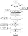
도 1은 기존에 제어 정보를 데이터와 시간 다중화(time multiplexing)하여 전송하기 위한 하향링크 물리채널의 구조를 도시한 도면.1 is a diagram illustrating a structure of a downlink physical channel for transmitting control information by time multiplexing with data.
도 2는 기존에 제어 정보를 물리채널과 코드 다중화하여 전송하는 하향링크 물리채널의 구조를 도시한 도면.2 is a diagram illustrating a structure of a downlink physical channel for transmitting coded multiplexed control information to a physical channel.
도 3은 본 발명의 제 1실시 예에 따른 송신기의 구조를 도시한 도면.3 is a diagram illustrating a structure of a transmitter according to a first embodiment of the present invention.
도 4는 본 발명의 제 1실시 예에 따른 수신기의 구조를 도시한 도면.4 is a diagram illustrating a structure of a receiver according to the first embodiment of the present invention.
도 5는 본 발명의 제 1실시 예에 따른 제어 정보 추출기의 구조를 도시한 도면.5 is a diagram illustrating a structure of a control information extractor according to a first embodiment of the present invention.
도 6은 본 발명의 제 1실시 예에 따른 송/수신단에서 수행되는 동작을 도시한 도면.6 is a diagram illustrating an operation performed by a transmitting / receiving terminal according to a first embodiment of the present invention.
도 7은 본 발명의 제 2실시 예에 따른 송신기의 구조를 도시한 도면.7 is a diagram illustrating a structure of a transmitter according to a second embodiment of the present invention.
도 8은 본 발명의 제 2실시 예에 따른 수신기의 구조를 도시한 도면.8 is a diagram illustrating a structure of a receiver according to a second embodiment of the present invention.
도 9는 본 발명의 제 2실시 예에 따른 채널 추정기의 구조를 도시한 도면.9 is a diagram illustrating a structure of a channel estimator according to a second embodiment of the present invention.
도 10은 본 발명의 제 2실시 예에 따른 송/수신단에서 수행되는 동작을 도시 한 도면.10 is a diagram illustrating an operation performed by a transmitting / receiving terminal according to a second embodiment of the present invention.
도 11은 본 발명의 제 3실시 예에 따른 송신기의 구조를 도시한 도면.11 is a diagram illustrating a structure of a transmitter according to a third embodiment of the present invention.
도 12는 본 발명의 제 3실시 예에 따른 수신기의 구조를 도시한 도면.12 is a diagram showing the structure of a receiver according to a third embodiment of the present invention.
도 13은 본 발명의 제 3실시 예에 따른 채널 추정기의 구조를 도시한 도면.13 illustrates a structure of a channel estimator according to a third embodiment of the present invention.
도 14는 본 발명의 제 3실시 예에 따른 송/수신단에서 수행되는 동작을 도시한 도면.
14 is a view showing an operation performed at a transmitting / receiving end according to a third embodiment of the present invention.
본 발명은 이동통신 시스템에서 상향링크 패킷 데이터의 수신 여부를 나타내는 제어 정보를 전송하는 장치 및 방법에 관한 것이다.The present invention relates to an apparatus and method for transmitting control information indicating whether uplink packet data is received in a mobile communication system.
부호분할다중접속(Code Division Multiple Access : 이하 CDMA라 칭한다.) 이동통신시스템은 음성신호의 송/수신을 위주로 하는 IS-95 규격에서 발전하여, 현재 음성뿐만 아니라 고속 데이터의 전송이 가능한 IMT(International Mobile Telecommunication)-2000 규격이 구현되고 있다. 상기 IMT-2000 규격에서는 고품질의 음성, 동화상, 인터넷 검색 등의 서비스를 목표로 하고 있다.Code Division Multiple Access (hereinafter referred to as CDMA) A mobile communication system has been developed from the IS-95 standard, which focuses on the transmission / reception of voice signals, and is currently capable of transmitting high-speed data as well as voice. Mobile Telecommunication) -2000 standard has been implemented. The IMT-2000 standard aims to provide services such as high quality voice, moving picture, and Internet search.
전술한 바와 같이 이동통신시스템은 음성, 데이터 등의 정보를 서비스하기 위한 다양한 방안이 구현되고 있는데, 그 대표적인 예가 UMTS(Universal Mobile Terrestrial System) 통신 시스템에서의 고속 순방향 패킷 접속(High Speed Downlink Packet Access: HSDPA) 방식이다.As described above, the mobile communication system implements various methods for serving information such as voice and data, and a representative example thereof is High Speed Downlink Packet Access in a Universal Mobile Terrestrial System (UMTS) communication system. HSDPA) method.
일반적으로, 고속 순방향 패킷 접속(High Speed Downlink Packet Access)방식은 순방향 고속 패킷 데이터 전송을 지원하기 위한 순방향 데이터 채널인 고속 순방향 공통 채널(High Speed - Downlink Shared Channel : HS-DSCH)과 이와 관련된 제어 채널들을 사용하는 데이터 전송방식을 총칭한다. 상기 고속 순방향 패킷 데이터 서비스를 지원하기 위해서 적응적 변조방식 및 코딩 방식(Adaptive Modulation and Coding: 이하 "AMC"라 한다), 복합 재전송 방식(Hybrid Automatic Retransmission Request: 이하 "HARQ"라 함) 및 빠른 셀 선택(Fast Cell Select: 이하 "FCS"라 함)방식이 제안되었다. 이하 HARQ 방식, 특히 다채널 정지-대기 혼화 자동 재전송 방식(n-channel Stop And Wait Hybrid Automatic Retransmission Request:이하 "n-channel SAW HARQ"라 칭한다.)을 설명하기로 한다.In general, the high speed downlink packet access method includes a high speed downlink shared channel (HS-DSCH), which is a forward data channel for supporting forward high speed packet data transmission, and a control channel associated therewith. Collectively refers to the data transfer method that uses them. Adaptive Modulation and Coding (hereinafter referred to as "AMC"), Hybrid Automatic Retransmission Request (hereinafter referred to as "HARQ") and fast cells to support the fast forward packet data service. Fast cell select (hereinafter referred to as "FCS") has been proposed. Hereinafter, the HARQ scheme, in particular, an n-channel Stop And Wait Hybrid Automatic Retransmission Request (hereinafter referred to as "n-channel SAW HARQ") will be described.
상기 HARQ 방식은 ARQ(Automatic Retransmission Request) 방식의 전송 효율을 증가시키기 위해 다음과 같은 2 가지 방안을 새롭게 적용한 것이다. 첫 번째 방안은 이동 단말(User Equipment, 이하 UE라 칭한다)과 기지국(이하 Node B라 칭한다) 사이에서의 재전송 요구 및 응답을 수행하는 것이다. 두 번째 방안은 UE가 오류가 발생한 데이터들을 일시적으로 저장하고, 상기 저장된 데이터를 해당 데이터(오류가 발생한 데이터)의 재전송 데이터와 결합(Combining)해서 디코딩을 수행하는 것이다. 또한 고속 순방향 패킷 데이터 서비스 방식에서는 종래의 멈춤-대기 자동 재전송(Stop and Wait ARQ : SAW ARQ) 방식의 단점을 보완하기 위해서 상기 n-channel SAW HARQ 방식을 도입하였다. 상기 SAW ARQ 방식의 경우 이전 패킷 데이터 에 대한 ACK를 수신하여야만 다음 패킷 데이터를 전송한다. 이는 이전 패킷 데이터에 대한 ACK를 수신한 후에만 다음 패킷 데이터를 전송하기 때문에 패킷 데이터를 현재 전송할 수 있음에도 불구하고 ACK을 대기하여야 하는 경우가 발생할 수 있다The HARQ scheme newly applies the following two methods to increase the transmission efficiency of the ARQ (Automatic Retransmission Request) scheme. The first approach is to perform a retransmission request and response between a mobile terminal (hereinafter referred to as UE) and a base station (hereinafter referred to as Node B). The second method is for the UE to temporarily store the data in error, and combine the stored data with retransmission data of the data (in error data) to perform decoding. In addition, the high-speed forward packet data service scheme has introduced the n-channel SAW HARQ scheme to compensate for the disadvantages of the conventional Stop and Wait ARQ scheme. In the SAW ARQ scheme, the next packet data is transmitted only after receiving an ACK for the previous packet data. Since the next packet data is transmitted only after receiving an ACK for the previous packet data, there may be a case where the ACK must be waited even though the packet data can be transmitted at present.
상기 n-channel SAW HARQ 방식에서는 상기 이전 패킷 데이터에 대한 ACK를 받지 않은 상태에서 다수의 패킷 데이터들을 연속적으로 전송해서 채널의 사용 효율을 높일 수 있다. 즉, UE와 Node B간에 특정 시간 또는 채널 번호로 식별 가능한 n 개의 논리적인 채널(Logical Channel)들을 설정한다. 패킷 데이터를 수신하게 되는 상기 UE는 수신한 패킷 데이터가 어느 채널을 통해 전송된 패킷 데이터인지를 식별하여 수신되어야 할 순서대로 패킷 데이터들을 재구성하거나, 상기 패킷 데이터들을 소프트 컴바이닝(soft combining) 하는 등 필요한 조치를 취한다.In the n-channel SAW HARQ scheme, a plurality of packet data may be continuously transmitted without receiving an ACK for the previous packet data, thereby improving channel usage efficiency. That is, n logical channels that can be identified by a specific time or channel number are configured between the UE and the Node B. The UE, which receives the packet data, identifies which channel the received packet data is transmitted through, and reconstructs the packet data in the order in which it should be received, soft combines the packet data, etc. Take the necessary action.
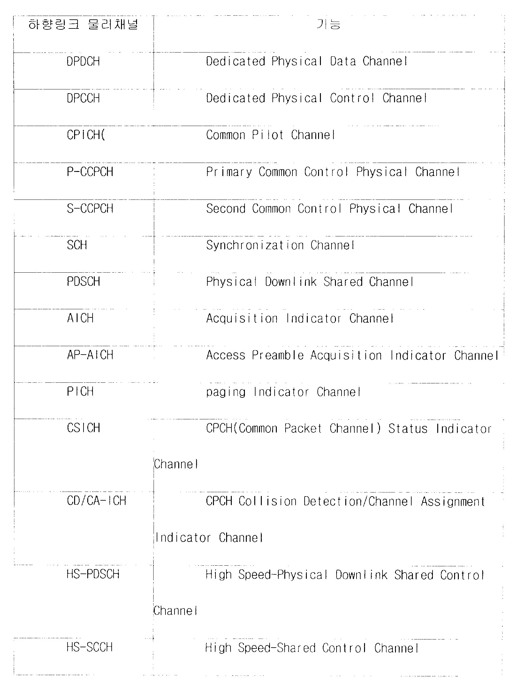
하기 〈표 1〉과 〈표 2〉는 이동통신 시스템의 하향링크와 상향링크에서 사용되는 물리채널을 나타내고 있다. Tables 1 and 2 show physical channels used in downlink and uplink of a mobile communication system.
상기 하향링크의 물리 채널들은 직교가변확산계수(orthogonal variable spreading factor :OVSF) 코드들 이용하여 구분한다.The downlink physical channels are classified using orthogonal variable spreading factor (OVSF) codes.
이동통신 시스템에서 상향링크로 패킷 데이터 서비스를 지원하기 위해서는 하향링크로 패킷 데이터 서비스를 지원하는 방안과 유사한 방안이 도입될 수 있다. 따라서 하향링크와 마찬가지로 상향링크에서 패킷 서비스를 구성하기 위해서는 상향링크의 패킷 데이터와 하향링크의 제어 정보들을 전달할 수 있어야 한다.
ARQ 방식 및 상기 n-channel SAW HARQ 방식을 사용하는 상향링크 패킷 데이터 서비스에서 하향링크를 이용하여 상기 패킷 데이터를 오류 없이 수신하였는지의 여부에 대한 제어정보(이하 “ACK/NACK 정보”라 한다.)를 전송하는 방안에 대해 알아본다. 상기 하향링크를 이용하여 상기 ACK/NACK 정보를 포함하는 제어 정보들을 전송하는 방안은 시간 다중화(time multiplexing)하여 전송하는 방안과 코드 다중화(code multiplexing)하여 전송되는 방안으로 구분된다.In order to support the packet data service in the uplink in the mobile communication system, a scheme similar to the method of supporting the packet data service in the downlink may be introduced. Therefore, in order to configure a packet service in uplink as in downlink, it is necessary to transmit uplink packet data and downlink control information.
Control information on whether or not the packet data is received without error by using downlink in the uplink packet data service using the ARQ scheme and the n-channel SAW HARQ scheme (hereinafter, referred to as “ACK / NACK information”). Learn how to send. The method of transmitting control information including the ACK / NACK information using the downlink is divided into a method of transmitting by time multiplexing and a method of transmitting by code multiplexing.
이하 도 1을 이용하여 시간 다중화 방안에 대해 알아본 후, 도 2를 이용하여 코드 다중화 방안에 대해 알아본다.Hereinafter, a time multiplexing scheme will be described with reference to FIG. 1, and a code multiplexing scheme will be described with reference to FIG. 2.
상기 도 1은 제어 정보로써의 ACK/NACK 정보를 데이터와 시간 다중화하여 전 송하기 위한 하향링크 물리채널의 구조를 도시하고 있다. 상기 하향링크에 있어서 물리채널의 종류와 기능에 대해서는 상기 〈표 1〉에 기재되어 있는 바와 같다. 상기 도 1에 의하면 제어 정보인 상기 ACK/NACK 정보는 물리채널의 데이터를 천공하여 생성된 공간에 시간 다중화되어 전송된다. 즉, 상기 물리채널은 데이터를 전송하지 않는 일부구간에 상기 ACK/NACK 정보를 포함하여 전송한다.FIG. 1 illustrates a structure of a downlink physical channel for time-multiplexing and transmitting ACK / NACK information as control information with data. The types and functions of physical channels in the downlink are as described in Table 1. According to FIG. 1, the ACK / NACK information, which is control information, is time-multiplexed and transmitted to a space generated by puncturing data of a physical channel. That is, the physical channel transmits the ACK / NACK information including a part of the data section.
상기 도 2는 제어 정보인 ACK/NACK 정보를 기존의 물리채널과 코드 다중화하여 전송하는 하향링크 물리채널의 구조를 도시하고 있다. 상기 도 2에 의하면 기존 물리채널 이외에 ACK/NACK 정보를 전송하기 위한 별도의 물리채널을 생성하고, 상기 생성된 물리채널을 통해 상기 ACK/NACK 정보를 전송한다. 상기 기존 물리채널과 상기 ACK/NACK 정보 전송을 위한 물리채널은 상기한 바와 같이 OVSF 코드를 이용하여 분리한다. 또한, 상기 ACK/NACK 정보를 전송하기 위한 채널은 ACK/NACK 정보 전송채널을 표시하는 제어정보를 포함할 수 있다.FIG. 2 illustrates a structure of a downlink physical channel for performing code multiplexing on ACK / NACK information, which is control information, with an existing physical channel. Referring to FIG. 2, a separate physical channel for transmitting ACK / NACK information is generated in addition to the existing physical channel, and the ACK / NACK information is transmitted through the generated physical channel. The existing physical channel and the physical channel for transmitting the ACK / NACK information are separated using the OVSF code as described above. In addition, the channel for transmitting the ACK / NACK information may include control information indicating the ACK / NACK information transmission channel.
상기 도 1에 의한 방안은 기존 물리채널의 일부 구간에 제어 정보인 ACK/NACK 정보를 포함시켜야 하므로 기존 물리채널로 전송되는 데이터의 일부가 손실될 우려가 있다. 또한 상기 도 2에 의한 방안은 기존 물리채널의 데이터 손실은 발생되지 않지만 제어 정보인 ACK/NACK 정보를 전송하기 위해 생성한 물리채널을 추가적인 전력과 OVSF코드가 사용되어야 한다는 문제점이 있다. 따라서 상기한 문제점을 해결하기 위한 방안이 논의된다.
The scheme according to FIG. 1 includes ACK / NACK information, which is control information, in some sections of the existing physical channel, so that a part of data transmitted on the existing physical channel may be lost. In addition, the method according to FIG. 2 has no problem that data loss of the existing physical channel does not occur, but additional power and OVSF code should be used for the physical channel generated for transmitting ACK / NACK information, which is control information. Therefore, a method for solving the above problem is discussed.
따라서 전술한 종래 기술의 문제점을 해결하기 위한 본 발명의 목적은 패킷 데이터에 대한 제어 정보를 별도의 채널을 부가하지 않고 전송하는 장치 및 방법을 제안함에 있다. Accordingly, an object of the present invention is to propose an apparatus and method for transmitting control information on packet data without adding a separate channel.
본 발명의 다른 목적은 패킷 데이터에 대한 제어 정보를 다른 데이터의 손실 없이 전송하는 장치 및 방법을 제안함에 있다.Another object of the present invention is to propose an apparatus and method for transmitting control information on packet data without loss of other data.
본 발명의 또 다른 목적은 별도의 채널이나 코드를 사용하지 않고 제어 정보를 전송함으로써 성능이 저하하는 것을 방지하는 장치 및 방법을 제안함에 있다.It is still another object of the present invention to propose an apparatus and method for preventing performance degradation by transmitting control information without using a separate channel or code.
상기 본 발명의 목적들을 이루기 위한 이동통신 시스템에서 데이터의 수신 여부에 대한 정보를 전송하는 방법에 있어서, 수신 데이터에 대한 오류 유무에 따라 서로 다른 부호를 갖는 파일럿 신호를 생성하는 과정과, 상기 생성된 파일럿 신호를 전용 물리채널 프레임에 부가하여 전송하는 과정으로 이루어짐을 특징으로 한다.In the method for transmitting information on whether or not to receive data in a mobile communication system for achieving the objects of the present invention, the step of generating a pilot signal having a different code according to the presence or absence of errors on the received data, and the generated The pilot signal is added to a dedicated physical channel frame and transmitted.
상기 본 발명의 목적들을 이루기 위한 이동통신 시스템에서 데이터의 수신 여부에 대한 정보를 수신하는 방법에 있어서, 전용 물리채널 프레임으로부터 상기 데이터의 오류 유무에 대응되는 부호를 가지는 파일럿 신호를 검출하는 과정과, 상기 검출된 파일럿 신호에 따라 상기 데이터에 대한 전송오류를 판단하고, 상기 판단 결과에 따라 상기 데이터의 재 전송 여부를 결정하는 과정으로 이루어짐을 특징으로 한다.A method for receiving information on whether data is received in a mobile communication system for achieving the objects of the present invention, the method comprising: detecting a pilot signal having a code corresponding to an error of the data from a dedicated physical channel frame; And determining a transmission error for the data according to the detected pilot signal, and determining whether to retransmit the data according to the determination result.
삭제delete
삭제delete
이하 본 발명이 바람직한 실시 예를 첨부한 도면의 참조와 함께 상세히 설명한다. 또한 본 발명을 설명함에 있어서, 관련된 공지기능 혹은 구성에 대한 구체적인 설명이 본 발명의 요지를 불필요하게 흐릴 수 있다고 판단된 경우 그 상세한 설명은 생략한다.Hereinafter, the present invention will be described in detail with reference to the accompanying drawings. In describing the present invention, when it is determined that a detailed description of a related known function or configuration may unnecessarily obscure the subject matter of the present invention, the detailed description thereof will be omitted.
후술 될 본 발명에서는 기존과 같이 별도의 코드 또는 시간을 할당하여 제어 정보를 전송하지 않고, 통상적인 파일럿 채널의 심볼/비트 패턴을 이용하여 제어 정보를 송/수신하는 방안을 제안하도록 한다. 이를 위해 본 발명에서는 세 가지의 실시 예들을 게시한다. 그 첫 번째 실시 예는 전용물리채널(Dedicated Physical Channel, 이하 DPCH라 칭한다)의 파일럿 필드를 통해 제어 정보로써 ACK/NACK을 전송하는 방안을 제안한다. 그 두 번째 실시 예는 DPCH의 파일럿 필드를 빔 포밍(beam forming)을 지원하기 위한 기준(reference)으로써 사용함과 동시에, 상기 파일럿 필드를 통해 제어 정보로써 ACK/NACK을 전송하는 방안을 제안한다. 그 세 번째 실시 예는 직교 패턴 셋의 생성에 따라 2개 이상의 제어 정보로써, ACK/NACK/MISS를 전송하는 방안을 제안한다. 세 번째 실시 예에서는 이해를 돕기 위하여, 제어정보로서 ACK/NACK/MISS를 전송하는 방법에 대해서만 설명한다. 그러나 ACK/NACK/MISS 이외에 다른 제어 정보도 본 발명이 제안하는 장치와 방법에 의하여 전송할 수 있다.
<제 1실시 예>The present invention to be described later proposes a method of transmitting / receiving control information using a symbol / bit pattern of a conventional pilot channel without transmitting control information by allocating a separate code or time as in the prior art. To this end, the present invention discloses three embodiments. The first embodiment proposes a method of transmitting ACK / NACK as control information through a pilot field of a dedicated physical channel (hereinafter referred to as DPCH). The second embodiment proposes to use the pilot field of the DPCH as a reference for supporting beam forming and to transmit ACK / NACK as control information through the pilot field. The third embodiment proposes a method of transmitting ACK / NACK / MISS as two or more pieces of control information according to generation of an orthogonal pattern set. In the third embodiment, only a method of transmitting ACK / NACK / MISS as control information will be described. However, other control information besides ACK / NACK / MISS can also be transmitted by the apparatus and method proposed by the present invention.
<First Embodiment>
삭제delete
이하 첨부된 도면을 참조하여 본 발명의 제 1실시 예에 대해 구체적으로 살펴보면 다음과 같다.Hereinafter, a first embodiment of the present invention will be described in detail with reference to the accompanying drawings.
본 발명에서 제안하고자 하는 제 1실시 예는, ACK/NACK 정보를 통상적인 하향링크 DPCH의 파일럿 필드에 대한 위상 변조를 통해 전송하는 방법이다. 상기 제 1실시 예로써 제안된 방법에서는 전용 채널의 위상 기준이 CPICH(Common Pilot Channel)일 때를 가정하고 있다. 상기 전용 채널인 DPCH는 제어 채널인 DPCCH와 데이터 채널인 DPDCH가 시간 다중화되어 전송된다. 상기 DPCCH를 통해 전용 채널의 위상 기준, 즉 채널 보상을 위한 전용 채널 추정(dedicated channel estimation)이나 빔 포밍(beam forming)을 지원하기 위한 기준(reference)으로써 사용할 수 있는 파일럿 필드를 전송하였다. 본 발명의 제 1실시 예에서는 CPICH를 통해서 상기 파일럿 필드의 역할을 대신하게 한다.The first embodiment proposed in the present invention is a method of transmitting ACK / NACK information through phase modulation on a pilot field of a conventional downlink DPCH. In the method proposed as the first embodiment, it is assumed that a phase reference of a dedicated channel is a common pilot channel (CPICH). The dedicated channel DPCH is transmitted by time multiplexing the control channel DPCCH and the data channel DPDCH. A pilot field that can be used as a phase reference of a dedicated channel, that is, a reference for supporting dedicated channel estimation or beamforming for channel compensation, is transmitted through the DPCCH. In the first embodiment of the present invention, the CPICH takes the role of the pilot field.
도 3은 본 발명의 제 1실시 예에 따른 ACK/NACK 정보를 전송하기 위한 송신기의 구조를 도시하고 있다. 3 illustrates a structure of a transmitter for transmitting ACK / NACK information according to the first embodiment of the present invention.
이하 상기 도 3을 이용하여 본 발명의 제1실시 예에 따른 ACK/NACK 정보를 전송하는 송신기의 구조에 대해 알아본다. 상기 송신기는 DPDCH 생성부(300), DPCCH 생성부(302), 다중화기(304), 파일럿비트 삽입부(306), 변조부(308), 파일럿 비트 생성부(312), ACK/NACK 정보 변환부(314), 곱셈기(310)로 구성된다.Hereinafter, a structure of a transmitter for transmitting ACK / NACK information according to the first embodiment of the present invention will be described with reference to FIG. 3. The transmitter includes a
UE의 상향링크 패킷 데이터를 수신한 Node B은 상기 수신된 데이터를 복조한다. 상기 복조 결과 상기 Node B는 수신된 데이터에 대한 오류 여부를 분석하여 ACK/NACK 정보를 생성한다. 상기 수신된 데이터에 대해 오류가 발생하면 재전송을 요청하는 NACK 정보를 생성하고, 상기 수신된 데이터에 대해 오류가 발생하지 않으면 재전송을 요청하지 않는 ACK 정보를 생성한다. 상기 생성된 ACK/NACK 정보는 ACK/NACK 신호 변환부(314)로 전달된다.
상기 ACK/NACK 신호 변환부(314)는 전달 받은 ACK/NACK 정보에 따라 특정 ACK/NACK 신호를 발생한다. 즉, 상기 전달 받은 정보가 ACK 정보이면 +1의 값을 가지는 신호를 발생하고, 상기 전달 받은 정보가 NACK 정보이면 -1의 값을 가지는 신호를 발생한다. 상기 전달 받은 정보에 따라 발생되는 ACK/NACK 신호의 값은 사용자의 선택에 따라 달라질 수 있다. 즉, 다른 실시예로서 ACK/NACK 정보 변환부(314)는 상기 전달 받은 정보가 ACK 정보이면 -1을 발생하고, 상기 전달 받은 정보가 NACK 정보이면 +1을 발생할 수 있다. 하지만, 일반적으로 상기 ACK/NACK신호 변환부(314)는 기본값으로 +1을 출력하며, 전달 받은 ACK/NACK 정보가 ACK 정보이면 -1을 발생한다. 상기 ACK/NACK 신호 변환부(314)의 기본값을 +1로 설정하는 이유는, ACK/NACK 정보가 전달되지 않는 경우 기존 표준 안에서 제시한 조건을 만족하기 위해서 이다. 상기 ACK/NACK 신호 변환부(314)는 상기 생성된 ACK/NACK 신호를 곱셈기(310)로 전달한다.
상기 파일럿(pilot) 비트 생성부(312)는 소정 파일럿 패턴을 가지는 파일럿 신호를 생성한다. 상기 생성되는 파일럿 패턴에 대한 정의는 3GPP 규격 TS25.211에 정의 되어 있다. 그러나 다른 파일럿 패턴에 대하여도 본 발명이 수월하게 적용될 수 있음은 자명하다. 상기 생성된 파일럿 신호는 곱셈기(310)로 전달한다. 상기 곱셈기(310)는 상기 전달 받은 파일럿 신호와 상기 ACK/NACK 신호 변환부(314)로부터 전달 받은 ACK/NACK 신호에 대한 곱셈 연산을 수행한다. 하기 〈수학식 1〉은 곱셈기(310)에서 수행되는 동작을 나타낸다.The Node B demodulating the uplink packet data of the UE demodulates the received data. As a result of the demodulation, the Node B generates ACK / NACK information by analyzing an error of the received data. When an error occurs in the received data, NACK information for requesting retransmission is generated. If no error occurs in the received data, ACK information for not requesting retransmission is generated. The generated ACK / NACK information is transmitted to the ACK /
The ACK /
The
![]()
![]()
여기서 si(n)는 상기 곱셈기(310)의 출력 신호이다. 상기 A(i)는 i번째 슬롯에 해당되는 ACK/NACK 정보 변환부(314)로부터 전달 받은 ACK/NACK 신호, 즉 “+1” 또는 “-1”이다. 상기 ![]()
한편, DPDCH(Dedicated Physical Data Channel) 생성부(300)는 전달 받은 DCH(Dedicated Channel) 데이터를 이용하여 DPDCH 데이터를 생성하고, 상기 생성된 DPDCH 데이터는 다중화기(304)로 전달된다. 상기 DPCCH(Dedicated Physical Control Channel) 생성부(302)는 DPDCH의 전송전력제어(Transmit Power Control : TPC) 정보와 전송포맷결합지시자(Transport Format Combination Indicator : TFCI)를 이용하여 DPCCH 데이터를 생성하고, 상기 생성된 DPCCH 데이터는 다중화기(304)로 전달된다. 상기 다중화기(304)는 상기 전달 받은 DPDCH 데이터와 DPCCH 데이터를 다중화하여 생성한 DPCH 데이터를 파일럿 비트 삽입부(306)로 전달한다.Where s i (n) is the output signal of the ![]()
Meanwhile, the dedicated physical data channel (DPDCH)
상기 파일럿 비트 삽입부(306)는 상기 곱셈기(310)로부터 전달 받은 신호를 상기 DPCH 데이터와 시간 다중화하여 DPCH 프레임을 출력한다. 상기 시간 다중화된 상기 DPCH 프레임은 변조부(308)에서 변조된 후 송신 안테나를 통해 전송된다.The pilot
도 4는 본 발명의 제 1실시 예에 따른 수신부의 구조를 도시하고 있다. DPDCH를 통해 전송된 데이터 및 DPCCH를 통해 전송된 제어 신호들은 각각 별도의 경로를 통하여 복조될 수 있으나 본 발명에서는 발명의 요지를 명확히 하기 위하여 관심 대상인 ACK/NACK 정보를 처리하는 경로만을 설명하기로 한다.
도시한 수신부에서, 송신부에서 전송한 DPCH 신호는 복조 과정을 거쳐 채널 보상기(400)로 전달된다. 채널 보상기(400)에서 채널 보상과정을 거친 수신신호는 복조부(402)에서 복조 과정을 수행한다. 또한, 상기 채널 보상기(400)에서 채널 보상 과정을 거친 상기 수신신호는 ACK/NACK 추출기(404)로 전달된다. 상기 ACK/NACK 추출기(404)는 상기 수신 신호에 포함된 파일럿 신호로부터 ACK/NACK 정보를 추출한다. 상기 ACK/NACK 추출기(404)에 대한 상세한 구조는 도 5에서 설명하기로 한다. 상기 ACK/NACK 추출기(404)에서 추출된 ACK/NACK 정보는 패킷 채널 조절기(406)로 전달된다. 상기 패킷 채널 조절기(406)는 상기 전달 받은 ACK/NACK 정보에 따라 이전 전송한 상향링크 패킷 데이터의 재전송 여부를 결정한다.
도 4에서는 파일럿 신호가 채널 보상기(400) 이후에 추출되는 것으로 설명되어 있으나 다른 실시예의 경우 채널 보상기(400) 이전에 채널 추정을 수행하기 위하여 추출된 파일럿 신호를 이용할 수도 있다. 즉 본 발명에서 ACK/NACK 판단을 위해 이용되는 파일럿 신호는 채널 보상 과정과 상관없이 어디에서든 추출 가능하다. 파일럿 신호의 추출 위치에 따른 수신부의 구현은 당업자 수준에서 용이할 것이다.4 illustrates a structure of a receiver according to a first embodiment of the present invention. The data transmitted through the DPDCH and the control signals transmitted through the DPCCH may be demodulated through separate paths, but the present invention will only describe a path for processing ACK / NACK information of interest to clarify the gist of the present invention. .
In the illustrated receiver, the DPCH signal transmitted by the transmitter is transmitted to the
Although FIG. 4 illustrates that the pilot signal is extracted after the
도 5는 본 발명의 제 1실시 예에 따른 ACK/NACK 추출기(404)의 구조를 도시하고 있다. 상기 ACK/NACK 추출기(404)는 DPCH 수신 판단기(502), DPCH 파일럿 추출기(500), DPCH 파일럿 필드 패턴 검출기(504), ACK/NACK 판별기(506)로 구성된다. 이하 상기 도 5를 이용하여 ACK/NACK 추출기(404)의 구조에 대해 상세하게 알아본다.5 shows a structure of an ACK /
상기 DPCH 수신 판단기(502)는 현재 수신하고자 하는 채널이 DPCH인지 여부를 판단한다. 현재 수신하고자 하는 채널이 DPCH이며, 현재 시간(타임슬롯)이 상향링크 패킷 채널의 채널 복호에 대한 처리 결과(즉 ACK/NACK 정보)를 수신하여야 하는 시간이면 이후 도 5의 나머지 구성들(500, 504, 506)이 동작하게 된다.
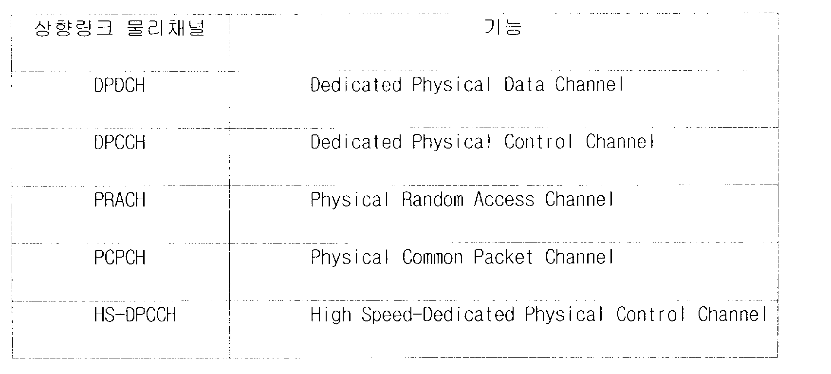
상기 DPCH 수신 판단기(502)에서 상기 수신하고자 하는 채널이 DPCH이며 상향링크 패킷 채널의 채널 복호 결과에 대한 정보를 수신하여야 하는 시간이라고 판단하면, 상기 DPCH 파일럿 추출기(500)는 상기 채널 보상기(400)의 출력인 수신 신호로부터 DPCH 신호의 파일럿 필드 성분만을 추출한다. 상기 추출된 파일럿 필드 성분은 DPCH 파일럿 필드 패턴 검출기(504)로 전달된다. 하기 〈수학식 2〉는 상기 DPCH 파일럿 필드 패턴 검출기(504)로 전달되는 신호를 나타낸다.The
When the
![]()
![]()
상기 ![]()
![]()
![]()
![]()
상기 ![]()
![]()
![]()
![]()
![]()
![]()
![]()
![]()
![]()
![]()
![]()
![]()
도 6은 본 발명의 제 1실시 예에 따른 송신부와 수신부의 동작을 도시하고 있다. 이하 상기 도 6을 이용하여 본 발명의 제 1실시 예에 따른 송신부와 수신부에서의 동작에 대해 상세하게 알아본다.6 illustrates operations of a transmitter and a receiver according to the first embodiment of the present invention. Hereinafter, the operation of the transmitter and the receiver according to the first embodiment of the present invention will be described in detail with reference to FIG. 6.
600단계에서 상기 송신단은 패킷 데이터에 대한 응답(Acknowledge) 타이밍인지 여부를 판단한다. 상기 600단계에서는 수신한 패킷 데이터에 대한 오류여부와 재전송 여부를 판단한다. 상기 판단 결과 응답 타이밍이면 602단계로 이동하고, 상기 판단 결과 응답 타이밍이 아니면 604단계로 이동한다. 여기서 응답 타이밍이 아니라는 것은 기지국이 단말이 전송한 상향링크 패킷 데이터를 수신하지 못한 경우를 의미할 수 있다.
상기 602단계에서 상기 송신단은 상향링크 패킷 채널 처리결과를 이진 ACK/NACK 신호로 변환한다. 상기 ACK/NACK 신호는 “+1” 또는 “-1”이 된다. 상기 “+1”은 수신된 패킷 데이터에 대해 오류가 발생하였음을(즉 NACK를) 의미하고, 상기 “-1”은 수신된 패킷 데이터에 대해 오류가 발생하지 않았음을(즉 ACK를) 의미한다. 상기 604단계에서는 기본값 "+1"을 가지는 ACK/NACK 신호가 생성된다. 606단계에서 상기 송신단은 상기 ACK/NACK 신호를 파일럿 신호와 곱하여 DPCH 프레임에 삽입한 후, 608단계에서 상기 DPCH 프레임에 대해 변조 과정을 수행한 후 수신단으로 전송한다. 참고로 608단계에서 610단계로의 진행은 무선 채널상의 전송이다. In
In
상기 610단계에서 상기 수신단은 상기 송신된 DPCH 신호를 수신하여 역확산한 후 612단계로 이동하여 채널 보상 과정을 수행한다. 614단계에서 상기 수신단은 채널 보상 과정을 거친 수신 신호에 대한 복조 과정과 채널 복호화 과정을 수행한다. 616단계에서 상기 수신단은 채널 보상 과정을 거친 수신신호로부터 ACK/NACK 신호를 추출한다. 상기 ACK/NACK 신호를 추출하는 과정에 대해서는 상기 도 5에서 설명한 바와 같다.
618단계에서 상기 수신단은 상기 ACK/NACK 신호를 바탕으로 상향링크 패킷 데이터의 재 전송여부를 결정한다. 즉, NACK일 경우 이전에 전송한 패킷 데이터를 다시 전송하고, ACK일 경우 새로운 패킷 데이터를 전송한다. 620단계에서 상기 송신단은 상기 상향링크 패킷 데이터에 대한 복조 및 복호화 과정을 수행하여 오류 유무를 판단하고, 상향링크 패킷 채널에 대한 처리 결과를 602단계로 전달한다.In
In
제 1실시 예와 같은 방법을 사용하면 ACK/NACK 여부에 따라 전용 파일럿의 위상이 반전되어 Node B과 UE가 미리 알고 있는 파일럿 패턴과 상이한 파일럿 패턴이 전송되므로, 채널 보상을 위한 전용 채널 추정을 위해 CPICH를 사용하는 경우에 바람직하다.Using the same method as in the first embodiment, since the phase of the dedicated pilot is inverted according to ACK / NACK and a pilot pattern different from the pilot pattern previously known to the Node B and the UE is transmitted, a dedicated channel estimation for channel compensation is performed. It is preferable when using CPICH.
<제 2실시 예>Second Embodiment
이하 첨부된 도면을 참조하여 본 발명의 제 2실시 예에 대해 구체적으로 살펴보면 다음과 같다.Hereinafter, a second embodiment of the present invention will be described in detail with reference to the accompanying drawings.
전술한 제 1실시 예는 CPICH를 전용 채널의 위상 기준으로 사용하는 경우에 적용된다. 그런데 일반적으로 시스템에 빔포밍 기법을 사용할 경우에는 DPCCH를 통해 전송되는 파일럿 필드가, UE 별로 정확한 빔을 생성하기 위해 수행되는 채널 추정 과정에서 위상 기준으로 사용된다. 따라서 제 2실시 예에서는 전용 파일럿 신호를 사용한 채널 추정에 대한 영향 없이 ACK/NACK 정보를 파일럿 필드에 싣는 방안에 대해 제안함으로써, 빔 포밍을 사용할 경우 CPICH 대신 DPCH의 파일럿 필드가 채널 추정을 위한 위상 기준으로 사용될 수 있도록 한다.The first embodiment described above is applied to the case where the CPICH is used as the phase reference of the dedicated channel. In general, when a beamforming technique is used in a system, a pilot field transmitted through a DPCCH is used as a phase reference in a channel estimation process performed to generate an accurate beam for each UE. Therefore, the second embodiment proposes a method of loading ACK / NACK information into a pilot field without affecting channel estimation using a dedicated pilot signal, so that when the beamforming is used, the pilot field of the DPCH instead of the CPICH has a phase reference for channel estimation. To be used.
도 7은 본 발명의 제 2실시 예에 따른 ACK/NACK 정보를 전송하기 위한 송신기의 구조를 도시하고 있다. 상기 제2실시 예는 ACK/NACK 정보를 기존 하향링크 DPCH의 파일럿 필드를 이용하여 전송하는 방안을 제안한다. 상기 송신기는 DPDCH 생성부(700), DPCCH 생성부(702), 다중화기(704), 파일럿 패턴 삽입부(706), 변조부(708), 파일럿 패턴 선택부(710)로 구성된다.7 illustrates a structure of a transmitter for transmitting ACK / NACK information according to the second embodiment of the present invention. The second embodiment proposes a method of transmitting ACK / NACK information using a pilot field of an existing downlink DPCH. The transmitter includes a
UE의 상향링크 패킷 데이터를 수신한 기지국은 상기 수신된 데이터를 복조한다. 상기 복조 결과 상기 기지국은 수신된 데이터에 대한 오류 여부를 분석하여 ACK/NACK 정보를 생성한다. 이때 상기 수신된 데이터에 대해 오류가 발생하면 재전송을 요청하는 NACK 정보를 생성하고, 상기 수신된 데이터에 대해 오류가 발생하지 않으면 재전송을 요청하지 않는 ACK 정보를 생성한다. 상기 생성된 ACK/NACK 정보는 파일럿 패턴 선택부(710)로 전달된다.
상기 파일럿 패턴 선택부(710)는 상기 전달 받은 ACK/NACK 정보에 따라 특정 ACK/NACK 파일럿 신호를 발생한다. 상기 전달 받은 ACK/NACK 정보가 ACK 정보이면 미리 정해지는 ![]()
![]()
![]()
![]()
![]()
![]()
![]()
![]()
DPDCH 생성부(700)는 전달 받은 DCH 데이터를 이용하여 DPDCH 데이터를 생성하고, 상기 생성된 DPDCH 데이터는 다중화기(704)로 전달된다. 상기 DPCCH 생성부(702)는 전달 받은 전송전력제어(Transmit Power Control : TPC) 정보와 전송포맷결합지시자(Transport Format Combination Indicator : TFCI) 정보를 이용하여 DPCCH 데이터를 생성하고, 상기 생성된 DPCCH 데이터는 다중화기(704)로 전달된다. 상기 다중화기(704)는 상기 전달 받은 DPDCH 데이터와 DPCCH 데이터를 다중화하여 생성한 DPCH 데이터를 파일럿 패턴 삽입부(706)로 전달한다. The base station receiving the uplink packet data of the UE demodulates the received data. As a result of the demodulation, the base station analyzes whether the received data is in error and generates ACK / NACK information. In this case, if an error occurs in the received data, NACK information for requesting retransmission is generated. If no error occurs in the received data, ACK information for not requesting retransmission is generated. The generated ACK / NACK information is transmitted to the
The ![]()
![]()
![]()
![]()
![]()
![]()
![]()
![]()
The
상기 파일럿 패턴 삽입부(706)는 상기 파일럿 패턴 선택부(710)로부터 전달 받은 상기 ACK/NACK 파일럿 신호를 상기 DPCH 데이터와 시간 다중화하여 DPCH 프레임을 생성한다. 상기 시간 다중화된 상기 DPCH 프레임은 변조부(708)에서 변조된 후 송신 안테나를 통해 전송된다.The
도 8은 본 발명의 제 2실시 예에 따른 수신부의 구조를 도시하고 있다. 상기 제 2실시 예는 채널보상 이전 단계에서 ACK/NACK 정보를 추출한다.
도시된 수신부에서, 송신부에서 전송한 수신 신호는 복조 과정을 거쳐 채널 추정기(804)와 채널 보상기(800)로 전달된다. 채널 추정기(804)에서는 상기 전달된 수신 신호를 이용하여 채널 추정과정을 수행함과 동시에 상기 전달된 수신 신호로부터 ACK/NACK 정보로 사용되는 파일럿 신호를 추출한다. 상기 채널 추정기(804)에 대한 상세한 내용에 대해서는 도 9를 이용하여 알아본다. 채널 추정기(804)에서 생성된 채널 추정치는 채널 보상기(800)로 전달되며, 상기 추출된 ACK/NACK 정보는 패킷 채널 조절기(806)로 전달된다. 상기 채널 보상기(800)에서 채널 보상 과정을 거친 수신 신호는 복조부(802)로 전달된다. 복조부(802)는 상기 수신신호를 복조하여 DPCH 데이터를 출력한다. 상기 패킷 채널 조절기(806)는 상기 전달 받은 ACK/NACK 정보에 따라 상향링크 패킷 데이터의 재전송 여부를 결정한다.
도 8에서는 파일럿 신호가 채널 추정 이전에 추출되는 것으로 설명되어 있으나 다른 실시예로서 채널 보상이 완료된 데이터 심벌로부터 파일럿 패턴을 추출하여 사용할 수도 있다. 즉 본 발명에서 ACK/NACK 정보로 이용되는 파일럿 신호는 채널 추정기(804)의 위치와 상관없이 어디에서든 추출 가능하다. 파일럿 신호의 추출위치에 따른 수신부의 구현은 당업자 수준에서 용이할 것이다.8 illustrates a structure of a receiver according to a second embodiment of the present invention. The second embodiment extracts ACK / NACK information in the step before channel compensation.
In the illustrated receiver, the received signal transmitted by the transmitter is transmitted to the
Although FIG. 8 illustrates that the pilot signal is extracted before channel estimation, in another embodiment, a pilot pattern may be extracted from a data symbol for which channel compensation is completed. That is, the pilot signal used as ACK / NACK information in the present invention can be extracted anywhere regardless of the position of the
도 9는 본 발명의 제 2실시 예에 따른 채널 추정기(804)의 구조를 도시하고 있다. 상기 채널 추정기(804)는 DPCH 수신 판단기(900)와 DPCH 파일럿 추출기(902)와 곱셈기들(904, 906)과 누적기들(908, 910)과 비교기(912)로 구성된다. 이하 상기 도 9를 이용하여 채널 추정기(804)의 구조에 대해 상세하게 알아본다.9 illustrates a structure of a
상기 DPCH 수신 판단기(900)는 현재 수신하고자 하는 채널이 DPCH인지 여부를 판단한다. 현재 수신하고자 하는 채널이 DPCH이며 현재 시간(타임슬롯)이 상향링크 패킷채널의 채널 복호에 대한 처리결과(즉 ACK/NACK 정보)를 수신하여야 하는 시간이면, 이후 도 9의 나머지 구성들(902 내지 914)이 동작하게 된다. The
상기 DPCH 수신 판단기(900)에서 상기 수신하고자 하는 채널이 DPCH이며 상기 채널 복호 결과에 대한 정보를 수신하여야 하는 시간이라고 판단하면, 상기 DPCH 파일럿 추출기(902)는 수신 신호로부터 DPCH 신호의 파일럿 필드 성분만을 추출한다. 상기 추출된 파일럿 필드 성분은 곱셈기들(904, 906)로 전달된다. 상기 곱셈기들(904, 906)은 상기 파일럿 필드 성분의 파일럿 심볼들을 전달 받는다. 하기 〈수학식 4〉는 상기 곱셈기들(904, 906)로 입력되는 신호를 나타낸다.When the
![]()
![]()
상기 ![]()
![]()
![]()
![]()
![]()
![]()
![]()
![]()
![]()
![]()
상기 〈수학식 5〉에서 알 수 있는 바와 같이 송신단에서 사용한 파일럿 패턴과 수신단의 어느 한 곱셈기로 입력된 파일럿 패턴이 동일할 경우에는 해당 곱셈기의 출력은 ![]()
상기 비교기(912)는 상기 누적기 1(908)과 누적기2(910)로부터 전달 받은 신호들의 크기 성분을 비교한다. 상기 비교 결과 누적기 1(908)이 전달한 신호 크기가 상기 누적기 2(910)가 전달한 신호 크기보다 클 경우, 상기 선택기(912)는 누적기 1(908)의 출력을 채널 추정치로서 출력한다. 상기 비교 결과 상기 누적기 2(910)가 전달한 신호가 상기 누적기 1(908)이 전달한 신호보다 클 경우 상기 선택기(912)는 누적기 2(910)의 출력을 채널 추정치로서 출력한다. 상기 선택기(912)는 상기 비교 결과에 따라 누적기1(908) 또는 누적기 2(910)의 출력을 채널 보상기(800)로 전달한다. As shown in Equation 5, when the pilot pattern used by the transmitter and the pilot pattern input by any of the multipliers of the receiver are the same, the output of the multiplier is ![]()
The
또한, ACK/NACK 판별기(914)는 상기 비교 결과에 따라 ACK/NACK을 판단하여 패킷 채널 조절기(806)로 전달한다. 구체적으로 상기 누적기1(908)의 출력 값이 누적기2(910)의 출력 값보다 큰 경우 NACK로 판단하며, 누적기2(910)의 값이 누적기1(908)의 값보다 큰 경우 ACK로 판단한다.
곱셈기들(904내지 906)에서 사용하는 파일럿 패턴들의 종류에 따라 선택된 누적기에 따른 ACK/NACK의 판단은 그에 대응하여 이루어진다. 즉, 해당 슬롯의 미리 설정된 파일럿 패턴을 곱하는 곱셈기의 값을 누적하는 누적기의 값이 선택된다면 NACK로 판단하고, ACK 정보의 파일럿 패턴을 곱하는 곱셈기의 값을 누적하는 누적기의 출력 값이 선택된다면 ACK로 판단하게 된다.Also, the ACK /
The determination of the ACK / NACK according to the accumulator selected according to the type of pilot patterns used in the
도 10은 본 발명의 제 2실시 예에 따른 송신부와 수신부의 동작을 도시하고 있다. 이하 상기 도 10을 이용하여 본 발명의 제 2실시 예에 따른 송신부와 수신부에서의 동작에 대해 상세하게 알아본다.10 illustrates operations of a transmitter and a receiver according to the second embodiment of the present invention. Hereinafter, the operation of the transmitter and the receiver according to the second embodiment of the present invention will be described in detail with reference to FIG. 10.
1000단계에서 상기 송신단은 패킷 데이터에 대한 응답 타이밍인지 여부를 판단한다. 상기 1000단계에서는 수신한 패킷 데이터에 대한 오류여부와 재전송 여부를 판단한다. 상기 판단 결과 응답 타이밍이면 1002단계로 이동하고, 상기 판단 결과 응답 타이밍이 아니면 1004단계로 이동한다. 상기 1002단계에서 송신단은 상기 상향링크 패킷 채널 처리결과에 대응되는 파일럿 패턴을 선택한다. 상기 상향링크 패킷 채널 처리결과에 대응되는 파일럿 패턴은 “![]()
![]()
![]()
![]()
![]()
상기 1002단계 또는 상기 1004단계로부터 선택된 파일럿 패턴은 1006단계로 전달된다. 1006단계에서 상기 송신단은 상기 선택된 파일럿 패턴을 가지는 파일럿 신호를 DPCH 프레임에 삽입한 후, 1008단계에서 상기 DPCH 프레임에 대해 변조 과정을 거쳐 수신단으로 전송한다. 참고로 1008단계에서 1010단계로의 진행은 무선 채널 상의 전송이다.In ![]()
![]()
![]()
![]()
![]()
The pilot pattern selected from
1010단계에서 상기 수신단은 상기 송신단에서 송신된 DPCH 신호를 수신하여 역확산한 후 1012단계로 이동하여 채널 추정 과정을 수행한다. 1014단계 내지 1016단계에서 상기 수신단은 상기 수신된 DPCH 신호에 대한 채널 보상 과정과 복조 및 채널 복호화 과정을 수행한다. 한편, 1018단계에서 상기 수신단은 상기 채널 추정 과정을 거친 수신신호로부터 ACK/NACK 정보에 해당하는 파일럿 신호의 파일럿 패턴을 추출한다. 상기 ACK/NACK 신호를 추출하는 과정에 대해서는 상기 도 9에서 설명한 바와 같다.
1020단계에서 상기 수신단은 상기 ACK/NACK 신호를 바탕으로 상향링크 패킷 데이터의 재 전송여부를 결정한다. 즉, NACK일 경우 이전에 전송한 패킷 데이터를 다시 전송하고, ACK일 경우 새로운 패킷 데이터를 전송한다. In
In
1022단계에서 상기 송신단은 상기 전달 받은 상향링크 패킷 데이터에 대한 복조 및 복호화 과정을 수행한다. 상기 송신단은 복조 및 복호화 과정을 통해 상기 상향링크 패킷 데이터에 대한 오류 유무를 판단하고, 상향링크 패킷 채널에 대한 처리 결과를 1002단계로 전달한다.In
<제 3실시 예>Third Embodiment
이하 첨부된 도면을 참조하여 본 발명의 제 3실시 예에 대해 구체적으로 살펴보면 다음과 같다.Hereinafter, a third embodiment of the present invention will be described in detail with reference to the accompanying drawings.
전술한 제 1 및 제 2실시 예에서는 2개의 제어 정보(ACK/NACK 정보)를 전송하는 방식에 관한 것이었으나 후술 될 제 3실시 예에서는 직교 패턴 셋이 생성되는 범위에서 2개 이상, 즉 복수 개의 제어 정보들을 전송하는 방식에 관한 것이다. 제 3실시 예에서는 제어 정보로써 MISS/ACK/NACK 정보를 가정하고 있다. 한편 제 3실시 예에서는 전용 파일럿을 사용한 채널 추정에 대한 영향 없이 MISS/ACK/NACK 정보를 파일럿 필드에 싣는 방안에 대해 제안할 것이다. 여기서 제어 정보로써 MISS 란 송신해야 할 시각에 패킷 데이터를 전송하였으나 수신측에서 이를 인지하지 못한 상황의 발생을 의미한다. 이 경우 수신측에서는 ACK 정보 또는 NACK 정보가 아닌 통상적인 파일럿 패턴 또는 미리 결정된 파일럿 패턴을 이용하여 MISS 정보를 전송하도록 한다.In the first and second embodiments described above, the present invention relates to a method of transmitting two control information (ACK / NACK information). However, in the third embodiment to be described later, two or more, i.e., a plurality of orthogonal pattern sets are generated. A method of transmitting control information. In the third embodiment, MISS / ACK / NACK information is assumed as control information. Meanwhile, the third embodiment will propose a method of loading MISS / ACK / NACK information in a pilot field without affecting channel estimation using a dedicated pilot. Here, as control information, MISS means a situation in which packet data is transmitted at a time to be transmitted but the receiver does not recognize it. In this case, the receiving side transmits the MISS information using a conventional pilot pattern or a predetermined pilot pattern instead of the ACK information or the NACK information.
도 11은 본 발명의 제 3실시 예에 따른 제어정보를 전송하기 위한 송신기의 구조를 도시하고 있다. 상기 제3실시 예는 제어정보로써 MISS/ACK/NACK 정보를 기존 하향링크 DPCH의 파일럿 필드를 이용하여 전송하는 방안을 제안한다. 상기 송신기는 DPDCH 생성부(1100), DPCCH 생성부(1102), 다중화기(1104), 파일럿 패턴 삽입부(1106), 변조부(1108), 파일럿 패턴 선택부(1110)로 구성된다.11 shows a structure of a transmitter for transmitting control information according to a third embodiment of the present invention. The third embodiment proposes a method of transmitting MISS / ACK / NACK information using a pilot field of an existing downlink DPCH as control information. The transmitter includes a
단말(UE)의 상향링크 패킷 데이터를 수신한 기지국은 상기 수신된 데이터를 복조한다. 상기 복조 결과 상기 기지국은 수신된 데이터에 대한 오류 여부를 분석하여 제어 정보를 생성한다. 이때, 상기 수신된 데이터에 대해 오류가 발생하면 재전송을 요청하는 NACK 정보를 생성하고, 상기 수신된 데이터에 대해 오류가 발생하지 않으면 해당 데이터를 정상적으로 수신하였음을 확인하는 ACK 정보를 생성한다. 하지만 원하는 시점에서 데이터가 수신되지 않은 것으로 판단되면, 해당 데이터를 수신하지 못하였음을 확인하는 MISS 정보를 생성한다. 상기 생성된 제어 정보는 파일럿 패턴 선택부(1110)로 전달된다.
상기 파일럿 패턴 선택부(1110)는 전달 받은 제어 정보에 따라 특정 파일럿 신호를 발생한다. 예컨대, 상기 제어 정보가 MISS 정보이면 미리 정해지는 ![]()
![]()
![]()
![]()
![]()
![]()
![]()
![]()
![]()
![]()
DPDCH 생성부(1100)는 전달 받은 DCH 데이터를 이용하여 DPDCH 데이터를 생성하고, 상기 생성된 DPDCH 데이터는 다중화기(1104)로 전달된다. 한편 상기 DPCCH 생성부(1102)는 전달 받은 전송전력제어(TPC) 정보와 전송포맷결합지시자(TFCI)를 이용하여 DPCCH 데이터를 생성하고, 상기 생성된 DPCCH 데이터는 다중화기(1104)로 전달된다. 상기 다중화기(1104)는 상기 전달 받은 DPDCH 데이터와 DPCCH 데이터를 다중화하여 생성한 DPCH 데이터를 파일럿 패턴 삽입부(1106)로 전달한다. The base station receiving the uplink packet data of the UE (UE) demodulates the received data. As a result of the demodulation, the base station analyzes whether the received data is in error and generates control information. In this case, when an error occurs in the received data, NACK information for requesting retransmission is generated. If an error does not occur in the received data, ACK information for confirming that the corresponding data is normally received is generated. However, if it is determined that the data has not been received at the desired time, it generates MISS information confirming that the data has not been received. The generated control information is transmitted to the
The ![]()
![]()
![]()
![]()
![]()
![]()
![]()
![]()
![]()
![]()
The
상기 파일럿 패턴 삽입부(1106)는 상기 파일럿 패턴 선택부(1110)로부터 전달 받은 상기 MISS/ACK/NACK 파일럿 신호를 상기 DPCH 데이터와 시간 다중화하여 DPCH 프레임을 생성한다. 상기 시간 다중화된 상기 DPCH 프레임는 변조부(1108)에서 변조된 후 송신 안테나를 통해 전송된다.The
도 12은 본 발명의 제 3실시 예에 따른 수신부의 구조를 도시하고 있다. 상기 제 3실시 예는 제1실시 예와 달리 채널보상 이전 단계에서 MISS/ACK/NACK 정보를 추출한다.
도시된 수신부에서, 송신부에서 전송한 수신 신호는 복조 과정을 거쳐 채널 추정기(1204)와 채널 보상기(1200)로 전달된다. 채널 추정기(1204)에서는 상기 전달된 수신 신호를 이용하여 채널 추정과정을 수행함과 동시에, 상기 전달된 수신 신호로부터 MISS/ACK/NACK 정보로 사용되는 파일럿 신호를 추출한다. 상기 채널 추정기(1204)에 대한 상세한 내용에 대해서는 도 13을 이용하여 알아본다. 채널 추정기(1204)에서 생성된 채널 추정치는 채널 보상기(1200)로 전달되며, 상기 추출된 MISS/ACK/NACK 정보는 패킷 채널 조절기(1206)로 전달된다. 상기 채널 보상기(1200)는 채널 추정기(804)에서 생성된 채널 추정치에 의해 채널 보상 과정을 수행한다. 상기 채널 보상기(1200)에서 채널 보상 과정을 거친 수신신호는 복조부(1202)로 전달된다. 복조부(1202)는 상기 수신신호를 복조하여 DPCH 데이터를 출력한다. 상기 패킷 채널 조절기(1206)는 상기 전달 받은 MISS/ACK/NACK 정보에 따라 상향링크 패킷 데이터의 재전송 여부를 결정한다.
도 12에서는 파일럿 신호가 채널 추정 이전에 추출되는 것으로 설명되어 있으나 변형된 실시예로서 채널 보상이 완료된 데이터 심벌로부터 파일럿 패턴을 추출하여 사용할 수도 있다. 즉 본 발명에서 MISS/ACK/NACK 정보로 이용되는 파일럿 신호는 채널 추정기(1204)의 위치와 상관없이 어디에서든 추출 가능하다. 파일럿 신호의 추출위치에 따른 수신부의 구현은 당업자 수준에서 용이할 것이다.12 illustrates a structure of a receiver according to a third embodiment of the present invention. Unlike the first embodiment, the third embodiment extracts MISS / ACK / NACK information before the channel compensation.
In the illustrated receiver, the received signal transmitted by the transmitter is transmitted to the
Although FIG. 12 illustrates that the pilot signal is extracted before channel estimation, the modified pilot pattern may be extracted from the data symbol for which channel compensation is completed. That is, the pilot signal used as MISS / ACK / NACK information in the present invention can be extracted anywhere regardless of the position of the
도 13은 본 발명의 제 3실시 예에 따른 채널 추정기(1204)의 구조를 도시하고 있다. 상기 채널 추정기(1204)는 DPCH 수신 판단기(1300)와 DPCH 파일럿 추출기(1302)와 곱셈기들(1304, 1306, 1308)과 누적기들(1310, 1312, 1314)과 비교기(1316)와 MISS/ACK/NACK 판별기(1318)로 구성된다. 이하 상기 도 13을 이용하여 채널 추정기(1204)의 구조에 대해 상세하게 알아본다.13 illustrates a structure of a
상기 DPCH 수신 판단기(1300)는 현재 수신하고자 하는 채널이 DPCH인지 여부를 판단한다. 현재 수신하고자 하는 채널이 DPCH이며, 현재 시간(타임슬롯)이 송신단에서 상향링크 패킷 채널의 채널 복호에 대한 처리 결과(즉 MISS/ACK/NACK 정보)를 수신하여야 하는 시간이면 이후 도 13의 나머지 구성들(1302 내지 1318)이 동작하게 된다.
상기 DPCH 수신 판단기(1300)에서 상기 수신하고자 하는 채널이 DPCH이며 수신단에서 상기 채널 복호 결과에 대한 정보를 수신하여야 하는 시간이라고 판단하면, 상기 DPCH 파일럿 추출기(1302)는 수신 신호로부터 DPCH 신호의 파일럿 필드 성분만을 추출한다. 상기 추출된 파일럿 필드 성분은 곱셈기들(1304, 1306, 1308)로 전달된다.The
When the
상기 곱셈기들(1304, 1306, 1308)은 상기 파일럿 필드 성분의 파일럿 심볼들을 전달 받는다. 하기 〈수학식 6〉는 상기 곱셈기들(1304 내지 1308)로 입력되는 파일럿 신호를 나타낸다.The
![]()
![]()
상기 ![]()
![]()
![]()
![]()
![]()
![]()
![]()
![]()
![]()
![]()
![]()
![]()
![]()
![]()
![]()
![]()

상기 <수학식 7>에서 k는 특정 누적기를 지정하는 인덱스이다. 예컨대, 누적기1(1310)을 지정하는 인덱스 k는 0이고, 누적기2(1312)를 지정하는 인덱스 k는 1이며, 누적기3(1314)을 지정하는 인덱스 k는 2이다.In Equation (7), k is an index that designates a specific accumulator. For example, the index k designating the
상기 〈수학식 7〉에서 알 수 있는 바와 같이 송신단에서 사용한 파일럿 패턴과 수신단의 어느 한 곱셈기로 입력된 파일럿 패턴이 동일할 경우에는 해당 곱셈기의 출력은 ![]()
상기 비교기(1316)는 상기 누적기 1(1310)과 상기 누적기2(1312) 및 상기 누적기3(1314)로부터 전달 받은 신호들의 크기 성분을 비교한다. 상기 크기 성분의 비교는 각 신호들의 절대 값을 비교하는 것으로 대신할 수 있다. 상기 비교에 의해 상기 비교기(1316)는 상기 누적기들(1310, 1312, 1314)로부터의 신호들 중 가장 큰 신호를 선택하여 출력한다. 이때 상기 선택된 신호에 대응한 k 값 또는 상기 k 값에 대응한 제어 정보가 출력된다.
상기 k 값이 출력되는 경우에는 상기 k 값에 의해 제어정보가 결정될 수 있다. 예컨대, 상기 누적기1(1310)이 전달한 신호가 나머지 누적기들(1312, 1314)이 전달한 신호들보다 클 경우 상기 비교기(1316)는 상기 누적기 1(1310)의 출력 값을 채널 추정치로 출력한다. 이때 상기 누적기1(1310)을 지정하는 k 값으로써 0이 출력된다. 한편 상기 비교에 의해 상기 누적기 2(1312)가 전달한 신호가 나머지 누적기들(1310, 1314)이 전달한 신호들보다 클 경우 상기 비교기(1316)는 상기 누적기 2(1312)의 출력 값을 채널 추정치로 출력한다. 이때 상기 누적기2(1312)를 지정하는 k 값으로써 1이 출력된다. 그렇지 않고 상기 비교에 의해 상기 누적기 3(1314)가 전달한 신호가 나머지 누적기들(1310, 1312)이 전달한 신호들보다 클 경우 상기 비교기(1316)는 상기 누적기 3(1314)의 출력 값을 채널 추정치로 출력한다. 이때 상기 누적기3(1314)를 지정하는 k 값으로써 2가 출력된다. As shown in Equation 7, when the pilot pattern used by the transmitter and the pilot pattern input by any of the multipliers of the receiver are the same, the output of the multiplier is ![]()
The
When the k value is output, control information may be determined by the k value. For example, when the signal transmitted by the
상기 비교기(1316)로부터 제어 정보가 출력되지 않고, k 값만이 출력되는 경우에는 MISS/ACK/NACK 판별기(1318)에 의해 제어 정보의 판별이 이루어진다. 즉 MISS/ACK/NACK 판별기(1318)는 상기 비교기(1316)를 통해 제공되는 k 값이 MISS 정보인지 ACK 정보인지 아니면 NACK 정보인지를 판단하여 패킷 채널 조절기(1206)로 통보한다. 예컨대, k 값이 0인 경우 제어 정보가 MISS 정보라고 판단하며, k 값이 1인 경우 제어 정보가 ACK이라 판단한다. 그리고 k 값이 2인 경우에는 제어 정보가 NACK이라 판단한다. 이러한 판단은 곱셈기들(1304 내지 1308)에서 사용하는 파일럿 패턴들과 k 값에 의해 제어 정보를 판단하는 미리 정해지는 기준에 따라 수행된다. If control information is not output from the
도 14는 본 발명의 제 3실시 예에 따른 송신부와 수신부의 동작을 도시하고 있다. 이하 상기 도 14를 이용하여 본 발명의 제 3실시 예에 따른 송신부와 수신부에서의 동작에 대해 상세하게 알아본다.14 illustrates operations of a transmitter and a receiver according to a third embodiment of the present invention. Hereinafter, the operation of the transmitter and the receiver according to the third embodiment of the present invention will be described in detail with reference to FIG. 14.
1400단계에서 상기 송신단은 패킷 데이터에 대한 응답 타이밍인지 여부를 판단한다. 상기 1400단계는 수신한 패킷 데이터에 대한 오류여부와 재전송 여부를 판단한다. 상기 판단 결과 응답 타이밍이면 1402단계로 이동한다. 그렇지 않고 상기 판단 결과 응답 타이밍이 아니면 1404단계로 이동한다.
상기 1402단계에서 상기 송신단은 상향링크 패킷 채널 처리결과에 대응되는 파일럿 패턴을 선택한다. 상기 상향링크 패킷 채널 처리결과에 대응되는 파일럿 패턴은 “![]()
![]()
![]()
![]()
![]()
![]()
![]()
상기 1402단계 또는 상기 1404단계로부터 파일럿 패턴이 결정되면, 1406단계로 진행한다. 상기 1406단계에서 상기 송신단은 상기 선택된 파일럿 패턴을 가지는 파일럿 신호를 시간 다중화를 통해 DPCH 프레임에 삽입한 후, 1408단계에서 상기 DPCH 프레임에 대해 변조 과정을 거쳐 수신단으로 전송한다. 참고로 1408단계에서 1410단계로의 진행은 무선 채널상의 전송이다.In step 1400, the transmitter determines whether it is a response timing to the packet data. In step 1400, it is determined whether the received packet data is error or not. If the determination result is a response timing, the flow proceeds to step 1402. Otherwise, if it is not the response timing, the process moves to step 1404.
In ![]()
![]()
![]()
![]()
![]()
![]()
![]()
If a pilot pattern is determined from
1410단계에서 수신단은 상기 송신단에서 송신된 DPCH 신호를 수신하여 역확산한 후 1412단계로 이동하여 채널 추정 과정을 수행한다. 1414단계 내지 1416단계에서 상기 수신단은 상기 수신된 DPCH 신호에 대한 채널 보상 과정과 복조 및 채널 복호화 과정을 수행한다. 1418단계에서 상기 수신단은 상기 채널 추정 과정을 거친 수신신호로부터 MISS/ACK/NACK 정보에 해당하는 파일럿 신호의 파일럿 패턴을 추출함으로써 송신측으로부터의 제어 정보를 획득한다.
상기 MISS/ACK/NACK 신호를 추출하여 제어 정보를 획득하는 과정에 대해서는 상기 도 13에서 설명한 바와 같다. 즉 수신단은 채널 추정 과정을 거친 신호들의 상관 값들을 비교하여 송신측으로부터의 제어 정보를 획득한다. 예컨대 제어 정보로써 MISS 정보가 획득되면 수신측은 송신측에서 원하는 패킷 데이터를 수신하지 못하였다고 판단하며, 제어 정보로써 ACK 정보가 획득되면 수신측은 송신측에서 원하는 패킷 데이터를 정상적으로 수신하였다고 판단한다. 그리고 제어 정보로써 NACK 정보가 획득되면 수신측은 송신측에서 원하는 패킷 데이터에 에러가 발생하였다고 판단한다. 그 후 1420단계에서 상기 수신측은 상기 확인된 제어 정보에 의해 이전 전송한 패킷 데이터를 재 전송하거나 다음 패킷 데이터를 전송한다. .In
The process of obtaining the control information by extracting the MISS / ACK / NACK signal is as described with reference to FIG. 13. That is, the receiver compares the correlation values of the signals that have undergone the channel estimation process and obtains control information from the transmitter. For example, if MISS information is obtained as control information, the receiver determines that the desired packet data has not been received by the transmitter. If ACK information is obtained as control information, the receiver determines that the desired packet data is normally received by the transmitter. When the NACK information is obtained as the control information, the receiver determines that an error has occurred in desired packet data at the transmitter. Thereafter, in
1422단계에서 상기 송신측은 상기 전달 받은 상향링크 패킷 데이터에 대한 복조 및 복호화 과정을 수행하고, 상기 복조 및 복호화 과정을 통해 상기 상향링크 패킷 데이터에 대한 오류 유무를 판단하고, 상향링크 패킷 채널에 대한 처리 결과에 대응한 제어 정보를 출력한다. 이때 상기 제어 정보는 MISS/ACK/NACK 정보 중 하나가 된다. 상기 송신측은 상기 제어 정보에 의해 전술한 상기 1402단계 내지 1408단계를 수행하게 된다.In
전술한 본 발명의 실시 예들에서는 하나의 슬롯을 이용해서 제어 정보(ACK/NACK 또는 MISS/ACK/NACK)를 전송하는 구성에 대해서만 살펴보았다. 하지만 보다 높은 신뢰도가 요구될 때에는 복수의 슬롯들에 걸쳐 파일럿 신호를 송/수신할 수 있음은 동일 기술 분야에서 통상의 지식을 가진 자에게는 자명할 것이다. 뿐만 아니라 한 슬럿에 전송되는 파일럿 비트 수가 2인 경우 두개의 제어 정보들을 전송할 수 있고, 파일럿 비트 수가 N개인 경우에는 N개의 제어 정보들을 전송할 수 있다.In the above-described embodiments of the present invention, only the configuration of transmitting control information (ACK / NACK or MISS / ACK / NACK) using one slot has been described. However, it will be apparent to those skilled in the art that pilot signals can be transmitted / received over multiple slots when higher reliability is required. In addition, when the number of pilot bits transmitted in one slot is 2, two control information may be transmitted. When the number of pilot bits is N, N control information may be transmitted.
전술한 바와 같이 본 발명은 기지국에서 상향링크 패킷 채널의 채널 처리 결과를 하향링크의 DPCH 파일럿 필드를 이용하여 송신하고, UE에서는 DPCH의 파일럿 필드를 추출하여 상향링크 패킷 채널의 채널 처리 결과를 판단하여 상향링크 패킷 채널의 ARQ 또는 HARQ를 동작하게 하는 방법에 대해 게시하고 있다. 따라서 본 발명은 상향링크 패킷 채널의 채널 디코딩 결과(제어 정보)를 전송하기 위하여 별도의 물리채널을 사용하지 않음으로써 추가적인 전력 및 OVSF 코드를 소비하지 않게 된다. 또한 상향링크 패킷 채널의 채널 처리 결과(제어 정보)를 기존의 물리채널의 데이터를 손실 시키지 않고 전송함으로써 물리채널의 성능이 저하되는 것을 방지하게 된다. 그 외에 다른 정보들의 전송을 위하여 하향링크에 물리채널을 하나 추가하는 경우 이를 통해 전송할 정보의 양을 줄일 수 있는 이득을 가진다.As described above, the present invention transmits the channel processing result of the uplink packet channel in the base station using the downlink DPCH pilot field, and extracts the pilot field of the DPCH in the UE to determine the channel processing result of the uplink packet channel. A method of operating ARQ or HARQ of an uplink packet channel is published. Therefore, the present invention does not consume additional power and OVSF code by not using a separate physical channel to transmit the channel decoding result (control information) of the uplink packet channel. In addition, by transmitting the channel processing result (control information) of the uplink packet channel without losing data of the existing physical channel, the performance of the physical channel is prevented from being degraded. In addition, when one physical channel is added to the downlink for transmission of other information, the amount of information to be transmitted through this can be reduced.
Claims (41)
Priority Applications (4)
| Application Number | Priority Date | Filing Date | Title |
|---|---|---|---|
| EP20050002948 EP1564923A1 (en) | 2004-02-12 | 2005-02-11 | Apparatus and method for transmitting control information in a mobile communication system |
| US11/055,631 US20050201486A1 (en) | 2003-11-15 | 2005-02-11 | Apparatus and method for transmitting control information in a mobile communication system |
| JP2005036929A JP2005244967A (en) | 2004-02-12 | 2005-02-14 | Apparatus and method for transmitting control information in mobile communication system |
| CNA2005100716756A CN1697363A (en) | 2004-02-12 | 2005-02-16 | Apparatus and method for transmitting control information in a mobile communication system |
Applications Claiming Priority (2)
| Application Number | Priority Date | Filing Date | Title |
|---|---|---|---|
| KR1020030080885 | 2003-11-15 | ||
| KR20030080885 | 2003-11-15 |
Publications (2)
| Publication Number | Publication Date |
|---|---|
| KR20050047027A KR20050047027A (en) | 2005-05-19 |
| KR100703382B1 true KR100703382B1 (en) | 2007-04-03 |
Family
ID=34431779
Family Applications (1)
| Application Number | Title | Priority Date | Filing Date |
|---|---|---|---|
| KR20040009401A Expired - Fee Related KR100703382B1 (en) | 2003-11-15 | 2004-02-12 | Apparatus and method for transmitting control information in mobile communication system |
Country Status (5)
| Country | Link |
|---|---|
| US (1) | US20050105640A1 (en) |
| EP (1) | EP1531576A3 (en) |
| JP (1) | JP2005151573A (en) |
| KR (1) | KR100703382B1 (en) |
| CN (1) | CN100393020C (en) |
Families Citing this family (20)
| Publication number | Priority date | Publication date | Assignee | Title |
|---|---|---|---|---|
| KR100929091B1 (en) | 2004-02-14 | 2009-11-30 | 삼성전자주식회사 | Apparatus and method for transmitting control information in mobile communication system |
| US20060023687A1 (en) * | 2004-07-27 | 2006-02-02 | Telefonaktiebolaget Lm Ericsson (Publ) | Fast reliable downlink signaling to support enhanced uplink services in a communication system |
| US8565194B2 (en) * | 2005-10-27 | 2013-10-22 | Qualcomm Incorporated | Puncturing signaling channel for a wireless communication system |
| KR100863791B1 (en) * | 2005-10-12 | 2008-10-17 | 삼성전자주식회사 | Transceiver and method and system for estimating channel using packet data control channel in frequency division multiple access communication system |
| WO2007055311A1 (en) * | 2005-11-11 | 2007-05-18 | Ntt Docomo, Inc. | Control channel allocation device, mobile communication system, and control channel allocation method |
| KR100881967B1 (en) | 2006-01-06 | 2009-02-04 | 삼성전자주식회사 | Method and apparatus for transmitting / receiving reverse information in monocarrier frequency division multiple access system |
| WO2007078146A1 (en) * | 2006-01-06 | 2007-07-12 | Samsung Electronics Co., Ltd. | Method and apparatus for transmitting/receiving uplink signaling information in a single carrier fdma system |
| WO2008060203A1 (en) * | 2006-11-13 | 2008-05-22 | Telefonaktiebolaget Lm Ericsson (Publ) | Method and arrangement for pilot pattern based control signalling in mimo systems |
| US8954105B2 (en) * | 2006-12-18 | 2015-02-10 | Samsung Electronics Co., Ltd. | Method and apparatus for transmitting/receiving data and control information through an uplink in a wireless communication system |
| CN101578803B (en) * | 2007-01-08 | 2013-06-12 | 诺基亚公司 | Method and apparatus for providing control signaling |
| JP4954782B2 (en) * | 2007-05-01 | 2012-06-20 | 株式会社エヌ・ティ・ティ・ドコモ | Base station apparatus and method in mobile communication system |
| CN103427928B (en) * | 2007-07-16 | 2017-08-04 | 三星电子株式会社 | The apparatus and method that information code element is sent and received in communication system |
| RU2433541C2 (en) | 2007-07-16 | 2011-11-10 | Самсунг Электроникс Ко., Лтд. | Apparatus and method for transmitting channel quality indicator and acknowledgement signals in sc-fdma communication systems |
| MY150961A (en) * | 2007-09-28 | 2014-03-31 | Interdigital Patent Holdings | Method and apparatus for high-speed transmission on rach |
| KR101074219B1 (en) * | 2008-03-27 | 2011-10-14 | 주식회사 세아네트웍스 | Method and apparatus for pilot signal transmission |
| CN105553533A (en) * | 2008-07-23 | 2016-05-04 | 中兴通讯股份有限公司 | Rank indication information sending method and device |
| KR101580004B1 (en) * | 2008-08-08 | 2015-12-24 | 파나소닉 인텔렉츄얼 프로퍼티 코포레이션 오브 아메리카 | Terminal device and receive method |
| CN104737487B (en) * | 2012-11-02 | 2018-03-02 | 联发科技(新加坡)私人有限公司 | Decode the method and user equipment of control channel in multiple subframes |
| GB2509161B (en) | 2012-12-21 | 2018-09-26 | Sony Corp | Telecommunications apparatus and method |
| CN109391406A (en) * | 2017-08-10 | 2019-02-26 | 株式会社Ntt都科摩 | Data transmission method for uplink, confirmation signal sending method, user equipment and base station |
Citations (1)
| Publication number | Priority date | Publication date | Assignee | Title |
|---|---|---|---|---|
| WO2003071723A1 (en) | 2002-02-19 | 2003-08-28 | Interdigital Technology Corporation | Method and apparatus for providing a highly reliable ack/nack for time division duplex (tdd) and frequency division duplex (fdd) |
Family Cites Families (7)
| Publication number | Priority date | Publication date | Assignee | Title |
|---|---|---|---|---|
| US5870406A (en) * | 1997-02-19 | 1999-02-09 | Ericsson Inc. | Automatic repeat request(ARQ) data communications method and apparatus |
| US6285663B1 (en) * | 1998-06-05 | 2001-09-04 | Telefonaktiebolaget Lm Ericsson (Publ) | Increasing performance in communications by embedding one signal in another signal |
| JP3397237B2 (en) * | 1998-09-29 | 2003-04-14 | 日本電気株式会社 | CDMA communication system, mobile station, and transmission power control method therefor |
| EP1271834B1 (en) * | 2001-05-14 | 2007-08-08 | LG Electronics, Inc. | Method for controlling data transmission in a radio communications system |
| US7310336B2 (en) * | 2001-05-18 | 2007-12-18 | Esa Malkamaki | Hybrid automatic repeat request (HARQ) scheme with in-sequence delivery of packets |
| KR100605859B1 (en) * | 2002-03-26 | 2006-07-31 | 삼성전자주식회사 | Method and apparatus for encoding and decoding channel quality indicator information in a communication system using a fast forward packet access method |
| US6996763B2 (en) * | 2003-01-10 | 2006-02-07 | Qualcomm Incorporated | Operation of a forward link acknowledgement channel for the reverse link data |
-
2004
- 2004-02-12 KR KR20040009401A patent/KR100703382B1/en not_active Expired - Fee Related
- 2004-11-12 US US10/985,969 patent/US20050105640A1/en not_active Abandoned
- 2004-11-12 JP JP2004329712A patent/JP2005151573A/en active Pending
- 2004-11-15 EP EP20040027071 patent/EP1531576A3/en not_active Ceased
- 2004-11-15 CN CNB2004100758608A patent/CN100393020C/en not_active Expired - Fee Related
Patent Citations (1)
| Publication number | Priority date | Publication date | Assignee | Title |
|---|---|---|---|---|
| WO2003071723A1 (en) | 2002-02-19 | 2003-08-28 | Interdigital Technology Corporation | Method and apparatus for providing a highly reliable ack/nack for time division duplex (tdd) and frequency division duplex (fdd) |
Also Published As
| Publication number | Publication date |
|---|---|
| JP2005151573A (en) | 2005-06-09 |
| KR20050047027A (en) | 2005-05-19 |
| EP1531576A2 (en) | 2005-05-18 |
| CN1652495A (en) | 2005-08-10 |
| EP1531576A3 (en) | 2006-09-06 |
| US20050105640A1 (en) | 2005-05-19 |
| CN100393020C (en) | 2008-06-04 |
Similar Documents
| Publication | Publication Date | Title |
|---|---|---|
| KR100929091B1 (en) | Apparatus and method for transmitting control information in mobile communication system | |
| KR100703382B1 (en) | Apparatus and method for transmitting control information in mobile communication system | |
| JP4361912B2 (en) | Control data transmission method in code division multiple access mobile communication system | |
| US7236474B2 (en) | Apparatus and method for reporting quality of downlink channel in W-CDMA communication systems supporting HSDPA | |
| EP1408712B1 (en) | Method and Apparatus for selecting a modulation scheme. | |
| JP3763805B2 (en) | Transmission / reception apparatus and method for reverse transmission power offset and high-speed forward common channel power level in a communication system using a high-speed forward packet connection scheme | |
| KR100754552B1 (en) | High speed common control channel transceiver and method in communication system using high speed forward packet access method | |
| KR100754633B1 (en) | Transceiver and Method for Packet Data Service in Mobile Communication System | |
| KR101513503B1 (en) | - method and apparatus for the reduction of cqi reporting overhead in mobile telecommunication system supporting dual-cell hsdpa | |
| US8208447B2 (en) | Pilot signal enhancements for a wireless communication system | |
| US20030095532A1 (en) | Coding apparatus and method in a CDMA mobile communication system | |
| KR20030044523A (en) | Apparatus and method for transmitting and receiving packet data in mobile telecommunication system | |
| JP4557982B2 (en) | Interference estimation in CDMA systems using alternative scrambling codes | |
| US20080125155A1 (en) | Radio access method, radio base station and radio terminal | |
| US20050201486A1 (en) | Apparatus and method for transmitting control information in a mobile communication system | |
| KR100876813B1 (en) | Power control device and method in mobile communication system | |
| JP2005244967A (en) | Apparatus and method for transmitting control information in mobile communication system | |
| KR100724978B1 (en) | Apparatus and method for controlling reverse transmission power in a communication system using a high speed forward packet access method | |
| EP1894324A1 (en) | Combined detection of transmission parameters and spreading factor in cdma communication system | |
| KR100810285B1 (en) | Apparatus for transferring high speed-downlink shared channel indicator to maintain compatibility in communication system using high speed downlink packet access scheme and method thereof | |
| KR20020064575A (en) | Preamble detection method and device in packet data transmission system | |
| EP1317093A1 (en) | Method for transmitting and retrieving an additional information in a data frame | |
| KR20050089264A (en) | Method and apparatus for efficient delivery of ack/nack information in hybrid-arq scheme for enhanced uplink packet transmission | |
| KR20060080980A (en) | Reverse packet data control channel processing method |
Legal Events
| Date | Code | Title | Description |
|---|---|---|---|
| PA0109 | Patent application |
St.27 status event code: A-0-1-A10-A12-nap-PA0109 |
|
| PG1501 | Laying open of application |
St.27 status event code: A-1-1-Q10-Q12-nap-PG1501 |
|
| A201 | Request for examination | ||
| P11-X000 | Amendment of application requested |
St.27 status event code: A-2-2-P10-P11-nap-X000 |
|
| P13-X000 | Application amended |
St.27 status event code: A-2-2-P10-P13-nap-X000 |
|
| PA0201 | Request for examination |
St.27 status event code: A-1-2-D10-D11-exm-PA0201 |
|
| PN2301 | Change of applicant |
St.27 status event code: A-3-3-R10-R13-asn-PN2301 St.27 status event code: A-3-3-R10-R11-asn-PN2301 |
|
| PN2301 | Change of applicant |
St.27 status event code: A-3-3-R10-R13-asn-PN2301 St.27 status event code: A-3-3-R10-R11-asn-PN2301 |
|
| D13-X000 | Search requested |
St.27 status event code: A-1-2-D10-D13-srh-X000 |
|
| D14-X000 | Search report completed |
St.27 status event code: A-1-2-D10-D14-srh-X000 |
|
| E902 | Notification of reason for refusal | ||
| PE0902 | Notice of grounds for rejection |
St.27 status event code: A-1-2-D10-D21-exm-PE0902 |
|
| P11-X000 | Amendment of application requested |
St.27 status event code: A-2-2-P10-P11-nap-X000 |
|
| P13-X000 | Application amended |
St.27 status event code: A-2-2-P10-P13-nap-X000 |
|
| E701 | Decision to grant or registration of patent right | ||
| PE0701 | Decision of registration |
St.27 status event code: A-1-2-D10-D22-exm-PE0701 |
|
| GRNT | Written decision to grant | ||
| PR0701 | Registration of establishment |
St.27 status event code: A-2-4-F10-F11-exm-PR0701 |
|
| PR1002 | Payment of registration fee |
St.27 status event code: A-2-2-U10-U11-oth-PR1002 Fee payment year number: 1 |
|
| PG1601 | Publication of registration |
St.27 status event code: A-4-4-Q10-Q13-nap-PG1601 |
|
| LAPS | Lapse due to unpaid annual fee | ||
| PC1903 | Unpaid annual fee |
St.27 status event code: A-4-4-U10-U13-oth-PC1903 Not in force date: 20100329 Payment event data comment text: Termination Category : DEFAULT_OF_REGISTRATION_FEE |
|
| PC1903 | Unpaid annual fee |
St.27 status event code: N-4-6-H10-H13-oth-PC1903 Ip right cessation event data comment text: Termination Category : DEFAULT_OF_REGISTRATION_FEE Not in force date: 20100329 |
|
| R18-X000 | Changes to party contact information recorded |
St.27 status event code: A-5-5-R10-R18-oth-X000 |