KR100594094B1 - Time and Frequency Synchronization Method for Reverse Link in Orthogonal Frequency Division Multiple Access Based Mobile Communication System - Google Patents
Time and Frequency Synchronization Method for Reverse Link in Orthogonal Frequency Division Multiple Access Based Mobile Communication System Download PDFInfo
- Publication number
- KR100594094B1 KR100594094B1 KR1020040006932A KR20040006932A KR100594094B1 KR 100594094 B1 KR100594094 B1 KR 100594094B1 KR 1020040006932 A KR1020040006932 A KR 1020040006932A KR 20040006932 A KR20040006932 A KR 20040006932A KR 100594094 B1 KR100594094 B1 KR 100594094B1
- Authority
- KR
- South Korea
- Prior art keywords
- time
- signal
- frequency
- preamble
- frequency synchronization
- Prior art date
- Legal status (The legal status is an assumption and is not a legal conclusion. Google has not performed a legal analysis and makes no representation as to the accuracy of the status listed.)
- Expired - Fee Related
Links
Images


Classifications
-
- H—ELECTRICITY
- H04—ELECTRIC COMMUNICATION TECHNIQUE
- H04L—TRANSMISSION OF DIGITAL INFORMATION, e.g. TELEGRAPHIC COMMUNICATION
- H04L27/00—Modulated-carrier systems
- H04L27/26—Systems using multi-frequency codes
- H04L27/2601—Multicarrier modulation systems
- H04L27/2647—Arrangements specific to the receiver only
- H04L27/2655—Synchronisation arrangements
- H04L27/2689—Link with other circuits, i.e. special connections between synchronisation arrangements and other circuits for achieving synchronisation
- H04L27/2692—Link with other circuits, i.e. special connections between synchronisation arrangements and other circuits for achieving synchronisation with preamble design, i.e. with negotiation of the synchronisation sequence with transmitter or sequence linked to the algorithm used at the receiver
-
- H—ELECTRICITY
- H04—ELECTRIC COMMUNICATION TECHNIQUE
- H04L—TRANSMISSION OF DIGITAL INFORMATION, e.g. TELEGRAPHIC COMMUNICATION
- H04L25/00—Baseband systems
- H04L25/02—Details ; arrangements for supplying electrical power along data transmission lines
- H04L25/03—Shaping networks in transmitter or receiver, e.g. adaptive shaping networks
- H04L25/03828—Arrangements for spectral shaping; Arrangements for providing signals with specified spectral properties
- H04L25/03834—Arrangements for spectral shaping; Arrangements for providing signals with specified spectral properties using pulse shaping
-
- H—ELECTRICITY
- H04—ELECTRIC COMMUNICATION TECHNIQUE
- H04L—TRANSMISSION OF DIGITAL INFORMATION, e.g. TELEGRAPHIC COMMUNICATION
- H04L27/00—Modulated-carrier systems
- H04L27/26—Systems using multi-frequency codes
- H04L27/2601—Multicarrier modulation systems
- H04L27/2626—Arrangements specific to the transmitter only
- H04L27/2627—Modulators
- H04L27/2628—Inverse Fourier transform modulators, e.g. inverse fast Fourier transform [IFFT] or inverse discrete Fourier transform [IDFT] modulators
-
- H—ELECTRICITY
- H04—ELECTRIC COMMUNICATION TECHNIQUE
- H04L—TRANSMISSION OF DIGITAL INFORMATION, e.g. TELEGRAPHIC COMMUNICATION
- H04L27/00—Modulated-carrier systems
- H04L27/26—Systems using multi-frequency codes
- H04L27/2601—Multicarrier modulation systems
- H04L27/2647—Arrangements specific to the receiver only
- H04L27/2655—Synchronisation arrangements
- H04L27/2657—Carrier synchronisation
-
- H—ELECTRICITY
- H04—ELECTRIC COMMUNICATION TECHNIQUE
- H04L—TRANSMISSION OF DIGITAL INFORMATION, e.g. TELEGRAPHIC COMMUNICATION
- H04L27/00—Modulated-carrier systems
- H04L27/26—Systems using multi-frequency codes
- H04L27/2601—Multicarrier modulation systems
- H04L27/2647—Arrangements specific to the receiver only
- H04L27/2655—Synchronisation arrangements
- H04L27/2662—Symbol synchronisation
-
- H—ELECTRICITY
- H04—ELECTRIC COMMUNICATION TECHNIQUE
- H04L—TRANSMISSION OF DIGITAL INFORMATION, e.g. TELEGRAPHIC COMMUNICATION
- H04L27/00—Modulated-carrier systems
- H04L27/26—Systems using multi-frequency codes
- H04L27/2601—Multicarrier modulation systems
- H04L27/2626—Arrangements specific to the transmitter only
- H04L27/2627—Modulators
- H04L27/2639—Modulators using other transforms, e.g. discrete cosine transforms, Orthogonal Time Frequency and Space [OTFS] or hermetic transforms
Landscapes
- Engineering & Computer Science (AREA)
- Computer Networks & Wireless Communication (AREA)
- Signal Processing (AREA)
- Physics & Mathematics (AREA)
- Spectroscopy & Molecular Physics (AREA)
- Power Engineering (AREA)
- Discrete Mathematics (AREA)
- General Physics & Mathematics (AREA)
- Mathematical Physics (AREA)
- Mobile Radio Communication Systems (AREA)
- Synchronisation In Digital Transmission Systems (AREA)
Abstract
본 발명에 따른, 다수의 단말이 전송하는 프리엠블 신호를 이용하여 기지국과 단말들의 시간/주파수를 동기화 하는 직교주파수분할다중접속 기반의 통신 시스템에서의 시간/주파수동기화 방법은 각각의 단말에서 프리엠블 신호를 생성하고, 기지국으로부터 수신되는 시간 참조 신호에 따라 프리엠블 신호를 시간 및 주파수 영역에서 보정하여 전송하고; 기지국에서 상기 단말들로부터 수신된 프리엠블 신호들을 분리하고, 각각의 단말로부터 수신된 프리엠블 신호를 이용하여 각각의 단말에 대한 시간 및 주파수 동기 오차를 추정하고, 추정된 시간 및 주파수 동기 오차를 해당 단말로 전송한다. According to the present invention, a time / frequency synchronization method in an orthogonal frequency division multiple access based communication system for synchronizing time / frequency of a base station and terminals by using a preamble signal transmitted by a plurality of terminals is a preamble at each terminal. Generating a signal, correcting and transmitting the preamble signal in time and frequency domain according to a time reference signal received from a base station; The base station separates the preamble signals received from the terminals, estimates time and frequency synchronization errors for each terminal using the preamble signals received from each terminal, and calculates the estimated time and frequency synchronization errors. Send to the terminal.
직교주파수분할다중접속, 시간 동기, 주파수 동기, 프리엠블, 파형 성형 필터Quadrature Frequency Division Multiple Access, Time Synchronization, Frequency Synchronization, Preamble, Waveform Shaping Filter
Description
도 1은 본 발명의 바람직한 실시예에 따른 사용자 단말의 프리엠블 생성 장치를 보인 블록도;1 is a block diagram showing a preamble generating device of a user terminal according to a preferred embodiment of the present invention;
도 2는 OFDMA 시스템의 역방향 프리엠블 신호 전송 과정을 설명하기 위한 도면;2 is a diagram illustrating a reverse preamble signal transmission process of an OFDMA system;
도 3은 본 발명의 바람직한 실시예에 따른 기지국 수신기의 시간/주파수 동기 오차 추정 장치를 보인 블록도;3 is a block diagram showing an apparatus for estimating time / frequency synchronization error of a base station receiver according to a preferred embodiment of the present invention;
도 4는 본 발명의 바람직한 실시예에 따른 파형 성형 필터 적용에 의한 주파수 응답 변화를 보인 그래프;4 is a graph showing a frequency response change by applying a waveform shaping filter according to a preferred embodiment of the present invention;
도 5a 및 도 5b는 각각 파형 성형 필터를 적용하지 않은 경우와 적용한 경우의 시간 동기 오차에 따른 누설 전력을 비교한 결과를 보인 그래프; 그리고5A and 5B are graphs showing the results of comparing the leakage power according to the time synchronization error with and without the waveform shaping filter, respectively; And
도 6은 본 발명에 따른 시간/주파수 동기 추정 방법과 종래의 푸리에 변환 이후의 위상변화 관찰을 통한 동기 추정 방법의 성능 비교 실험 결과를 보인 그래프이다.6 is a graph showing the results of performance comparison experiments of the time / frequency synchronization estimation method according to the present invention and the conventional synchronization estimation method by observing the phase change after the Fourier transform.
본 발명은 이동통신시스템에 관한 것으로, 더욱 상세하게는 직교주파수분할 다중접속 (Orthogonal Frequency Division Multiple Access: OFDMA) 기반의 이동통신 시스템에서의 시간 및 주파수 동기화 방법에 관한 것이다. The present invention relates to a mobile communication system, and more particularly, to a time and frequency synchronization method in an orthogonal frequency division multiple access (OFDMA) based mobile communication system.
차세대 이동통신에서는 보다 향상된 품질의 다양한 멀티미디어 서비스를 지원하기 위하여 고속 고품질의 데이터 전송이 요구된다. 이러한 요구에 만족하기 위한 기술의 하나로 최근에는 직교주파수분할다중접속 방식에 관한 연구가 활발히 진행되고 있다.In next generation mobile communication, high speed and high quality data transmission is required to support various multimedia services with higher quality. Recently, research on orthogonal frequency division multiple access has been actively conducted.
OFDM은 데이터를 서로 직교하는 협대역의 부반송파에 나누어 전송함으로써 광대역 전송 시 겪을 수 있는 주파수 선택적 페이딩 채널(frequency selective fading channel)에 의한 성능 열화를 감소시킨다. 또한, OFDM에서는 보호구간 (guard interval)의 삽입으로 다중 경로 페이딩에 의한 인접 심볼 간섭 (inter-symbol interference :ISI)의 문제를 해결한다. OFDM reduces performance degradation due to frequency selective fading channels that may be encountered in wideband transmission by dividing data into narrowband subcarriers orthogonal to each other. In addition, OFDM solves the problem of inter-symbol interference (ISI) due to multipath fading by inserting a guard interval.
통신 시스템에 있어서 초기 동기 포착은 매우 중요하며 특히 다중 반송파 기반의 통신 시스템은 타이밍 오차에 민감하므로 우수한 성능을 갖는 동기화 기법이 필수적으로 요구된다. Initial synchronization acquisition is very important in a communication system. Especially, a multicarrier-based communication system is sensitive to timing error, and therefore, a synchronization technique having excellent performance is required.
일반적으로, OFDMA 시스템에서는 보호구간을 사용하는 동기기법이나 패킷 모 드로 동작하는 시스템에서의 훈련 심볼(preamble)을 이용한 시간/주파수 동기 기법 등이 적용되고 있다. 이러한 기법들은 수신 신호의 반복 특성을 이용하는 것으로 OFDMA와 같은 다중 사용자 접속 방식에서는 수신 신호만으로 각각의 사용자를 구분할 수 없기 때문에 그대로 적용되기 어렵다. In general, in the OFDMA system, a synchronization technique using a guard interval or a time / frequency synchronization technique using a training symbol (preamble) in a system operating in a packet mode is applied. These techniques use the repetition characteristics of the received signal, and in a multi-user access method such as OFDMA, each user cannot be distinguished by the received signal alone.
이러한 OFDMA 환경에서의 시간 동기를 위해, 각 사용자가 다중 톤(tone) 신호를 전송하고 수신측에서 푸리에변환(FFT) 이후의 위상 변화를 관찰하여 각 사용자의 시간 동기를 추정하는 방법이 제안된 바 있다. 그러나 대부분의 다중 반송파 시스템에서는 시간 동기 추정은 시간 축에서 수행되고 각 사용자 신호를 분리하기 위해 주파수 축에서 동기를 추정하기 때문에 FFT 이후의 사용자간 간섭이 발생하지 않게 하기 위해 각 사용자의 시간 오차가 발생할 수 있는 길이만큼의 충분히 긴 순환 보호구간을 설정해주어야 하며, 이러한 긴 순환 보호구간은 시스템의 대역폭 효율을 감소시키는 원인이 된다.For the time synchronization in the OFDMA environment, a method of estimating the time synchronization of each user by transmitting a multi-tone signal and observing the phase change after the Fourier transform (FFT) at the receiving side has been proposed. have. However, in most multi-carrier systems, the time synchronization estimation is performed on the time axis, and since the synchronization is estimated on the frequency axis to separate each user signal, a time error of each user may occur to prevent interference between users after the FFT. It is necessary to set a long enough cyclic guard interval as long as possible, and this long cyclic guard interval causes a reduction in the bandwidth efficiency of the system.
본 발명은 상기와 같은 문제점을 해결하기 위해 창안된 것으로, 본 발명의 목적은 다중반송파 기반의 다중접속 시스템에서 기지국이 사용자 단말들 간의 직교성을 최대한 유지하면서 각 사용자 단말과 동기화를 수행할 수 있는 시간 및 주파수 동기화 방법을 제공하는 것이다. The present invention was devised to solve the above problems, and an object of the present invention is a time when a base station can perform synchronization with each user terminal while maintaining orthogonality between user terminals in a multi-carrier based multiple access system. And a frequency synchronization method.
본 발명의 또 다른 목적은 사용자 단말들간의 직교성 유지를 위한 과도한 순환 보호구간 없이 동기화를 수행하므로 우수한 대역폭 효율을 갖는 시간 및 주파수 동기화 방법을 제공하는 것이다.Another object of the present invention is to provide a time and frequency synchronization method having excellent bandwidth efficiency because synchronization is performed without excessive cyclic guard intervals for maintaining orthogonality between user terminals.
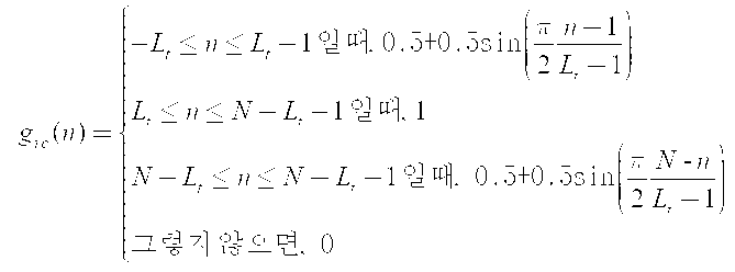
상기한 목적을 달성하기 위해, 본 발명에 따른 시간/주파수 동기화 방법은 각각의 단말에서 프리엠블 신호를 생성하고, 기지국으로부터 수신되는 시간 참조 신호에 따라 프리엠블 신호를 시간 및 주파수 영역에서 보정하여 전송하고; 기지국에서 상기 단말들로부터 수신된 프리엠블 신호들을 분리하고, 각각의 단말로부터 수신된 프리엠블 신호를 이용하여 각각의 단말에 대한 시간 및 주파수 동기 오차를 추정하고, 추정된 시간 및 주파수 동기 오차를 해당 단말로 전송하는 것을 특징으로 한다. 상기 프리엠블 생성 과정은 인접한 다수의 부반송파를 부대역으로 선택하여 임의의 신호열로 변조하고 나머지 부반송파들에는 0을 채워넣는 변조/매핑단계를 포함한다. 상기 부대역은 수학식: ![]()
![]()

인 것을 특징으로 한다. 상기 시간/주파수 동기 오차 추정 과정은 상기 수신된 프리엠블 신호를 N샘플 지연시키고, 상기 수신된 프리엠블 신호에 대해 해당 단말의 훈련신호(training signal)를 곱하고 무빙 섬(moving sum)을 취하여 산출된 값에 복소공액(complex conjugate)을 취하고, 상기 N샘플 지연된 프리엠블 신호에 대해 상기 훈련신호를 곱하여 무빙 섬을 취하고, 상기 복소공액을 취한 결과 값과 상기 N 샘플 지연된 프리엠블 신호에 대한 무빙 섬 결과 값을 곱하여 시간 동기 오차 매트릭을 산출하고, 상기 시간 동기 오차 매트릭에서 최대 시간동기 오차를 검출하고, 상기 최대 시간 동기 오차를 이용하여 주파수 동기 오차를 검출하는 것을 특징으로 한다. It is characterized by that. The time / frequency synchronization error estimation process is calculated by delaying the received preamble signal by N samples, multiplying the received preamble signal by a training signal of the corresponding terminal, and taking a moving sum. Taking a complex conjugate to a value, multiplying the training signal with the N sample delayed preamble signal to obtain a moving island, and taking the complex conjugate value and a moving island result for the N sample delayed preamble signal. The time synchronization error metric is calculated by multiplying the values, the maximum time synchronization error is detected from the time synchronization error metric, and the frequency synchronization error is detected using the maximum time synchronization error.
본 발명의 다른 일 국면에 있어서, 다수의 단말로부터 수신되는 프리엠블 신호를 이용하여 기지국이 시간/주파수 오차를 추정하는 직교주파수분할다중접속 기반의 통신 시스템에서, 상기 단말은: 인접한 다수의 부반송파를 부대역으로 선택하여 임의의 신호열로 변조하고 나머지 부반송파들에는 0을 채워 넣는 톤 선택기, 상기 톤 선택기의 출력 신호를 역푸리에 변환하는 역푸리에변환기, 상기 역푸리에변환기의 출력 신호를 직렬 신호열로 변환하는 병렬/직렬 변환기, 그리고 상기 병렬/직렬 변환기의 출력 신호를 임의의 시간 동기 오차에 대해서도 서로 다른 부대역 간의 간섭량을 최소화시킬 수 있도록 처리하는 파형 성형 필터를 포함한다. 상기 파형 성형 필터는 레이즈드 코사인 (Raised Cosine: RC)필터인 것을 특징으로 한다. 상기 파형 성형 필터의 시간 응답 특성은 수학식:In another aspect of the present invention, in an orthogonal frequency division multiple access based communication system in which a base station estimates time / frequency error using a preamble signal received from a plurality of terminals, the terminal includes: a plurality of adjacent subcarriers Selected as a subband to modulate an arbitrary signal sequence and fills the rest of the subcarriers with zeros; A parallel / serial converter, and a waveform shaping filter for processing the output signal of the parallel / serial converter to minimize the amount of interference between different subbands for any time synchronization error. The waveform shaping filter is a Raised Cosine (RC) filter. The time response characteristic of the waveform shaping filter is expressed by Equation:
인 것을 특징으로 한다. 상기 기지국은 수신된 신호로부터 분리된 특정 사용자 단말의 프리엠블 신호를 N샘플 구간동안 지연시키는 지연기, 상기 프리엠블 신호와 지연기의 출력 각각에 훈련신호를 곱하는 제1믹서 및 제2믹서, 상기 제1믹서 및 제2믹서의 출력에 대해 무빙 섬(moving sum) 연산을 수행하는 각각의 제1 무빙 섬 유닛 및 제2 무빙 섬 유닛, 상기 제1 무빙섬 유닛의 출력에 복소공액을 취하는 복소공액화기, 상기 제2 무빙 섬 유닛의 출력과 상기 복소공액화기의 출력을 이용하여 다수의 시간 동기 오차 산출하는 제3믹서, 상기 제3믹서로부터 산출된 시간 동기 오차들 중 최대 시간 동기 오차를 검출하는 최대값 검출기, 상기 최대값 검출기에 의해 검출된 최대 시간 동기 오차를 이용하여 주파수 동기 오차를 검출하는 연산기로 이루어진다.It is characterized by that. The base station includes a delayer for delaying a preamble signal of a specific user terminal separated from a received signal for N sample periods, a first mixer and a second mixer for multiplying each of the output signals of the preamble signal and the delayer with a training signal. A complex conjugate that takes a complex conjugate on the output of each of the first moving island unit and the second moving island unit and the first moving island unit to perform a moving sum operation on the outputs of the first mixer and the second mixer. A third mixer for calculating a plurality of time synchronization errors using the firearm, the output of the second moving island unit and the output of the complex conjugate, and detecting a maximum time synchronization error among the time synchronization errors calculated from the third mixer. And a calculator for detecting a frequency synchronization error using the maximum value detector and the maximum time synchronization error detected by the maximum value detector.
이하, 첨부된 도면을 참조하여 본 발명의 바람직한 실시예에 따른 시간/주파수 동기 방법을 설명한다. Hereinafter, a time / frequency synchronization method according to a preferred embodiment of the present invention with reference to the accompanying drawings.
도 1은 본 발명의 바람직한 실시예에 따른 사용자 단말의 프리엠블 생성 장치를 보인 도면이다. 1 is a view showing a preamble generating device of a user terminal according to an embodiment of the present invention.
도 1에서 보는 바와 같이, 상기 프리엠블 생성 장치는 인접한 몇 개의 부반송파 집합(부대역)을 선택하는 톤 선택기 (101), 상기 톤 선택기 (101)의 출력 신호들에 역푸리에 변환(Inverse Fast Fourier Transform: IFFT) 을 수행하는 역푸리에변환기(103), 상기 역푸리에변환기(103)로부터 출력되는 병렬 신호를 직렬 신호열로 변환하는 병력/직렬 변환기(105), 그리고 파형 성형 필터(spectral shaping filter, 107)로 구성된다. As shown in FIG. 1, the preamble generating apparatus includes a
상기 톤 선택기(101)는 부반송파들을 선택하여 임의의 신호열 {Cm }으로 변조하고 나머지 부반송파들에는 0을 채워넣는다. 상기 임의의 신호열은 상기 역푸리에 변환기(103)에 의해 변환된 후의 최종 신호열이 작은 첨두대평균전력비 (Peak to Average Power Ratio: PAPR)를 가지도록 선택된다. 이렇게 함으로써 수신측에서 정확히 같은 시간 동기 시점에서 푸리에 변환을 수행할 경우 다른 부대역으로의 신호 누설이 발생하지 않게 된다.The
다중경로 페이딩 환경에서 각 사용자의 시간 동기는 기지국과의 거리 등의 요소에 의해 서로 어긋나 있기 때문에 기지국에서 FFT를 이용하여 이러한 다른 사용자들의 신호를 완벽하게 분리해 내기 어렵다. In a multipath fading environment, the time synchronization of each user is shifted from each other by factors such as distance from the base station, so it is difficult for the base station to completely separate signals of these other users using the FFT.
각 사용자 단말의 신호 분리를 위해서는 해당 사용자가 임의의 시간 동기 오차가 발생할 것을 예측하고 그 보다 긴 순환 보호구간을 설정하여 프리엠블 신호를 전송하여야 하는데, 이 경우 과도한 대역폭 낭비를 가져온다. In order to separate the signal of each user terminal, the user must predict that a random time synchronization error will occur and set a longer cyclic protection interval to transmit a preamble signal, which causes excessive bandwidth waste.
본 발명에서는 순환 보호구간 대신에 파형 성형 필터를 사용하여 파형 성형 필터를 통과한 신호가 부대역 내에서는 자기 신호의 왜곡에 의해 원래의 전송 신호열 {Cm }을 그대로 복원해 내기 어렵게 되지만 그 대신 임의의 시간 동기 오차에 대해서도 서로 다른 부대역 간의 간섭량을 최소화시킬 수 있도록 선택된다. In the present invention, the signal passing through the waveform shaping filter by using the waveform shaping filter instead of the cyclic protection interval becomes difficult to recover the original transmission signal { C m } as it is due to the distortion of the magnetic signal in the subband, but instead the arbitrary In order to minimize the amount of interference between different subbands, the time synchronization error is selected.
본 발명에 따른 직교주파수분할다중접속(OFDMA) 기반의 통신 시스템에서는 초기접속을 시도하는 사용자나 동기 재설정이 필요한 사용자를 위한 시분할 된 동기시간 슬롯을 적용한다. 초기 접속을 하려는 각 사용자 단말은 K개의 부반송파 중에서 임의의 하나의 톤(tone) 집합을 선택한다. 이때, 톤 집합은 다음 수학식 1과 같이 표현할 수 있다.
![]()
![]()
삭제delete
여기서, k는 부반송파의 번호를 나타내며, Nf 는 한 개의 톤 집합에 포함된 부반송파의 개수이다. 동기 프리엠블을 위한 임의의 톤 집합은 시간 동기 및 주파수 동기 오차에 따른 다중 사용자 간섭을 최소화하기 위해서 트래픽 신호열과는 달리 다음 수학식 2에서와 같이 서로 인접한 부반송파를 이용하여 정의되는 것이 바람직하다.
![]()
![]()
삭제delete
이렇게 인접한 부반송파로 구성된 경우, 주파수 다이버시티 이득을 얻기 위해 단일 사용자 단말이 2개 또는 그 이상의 부대역을 동시에 사용할 수도 있다. 이와 같이 선택된 톤 집합을 이용하여 구성된 p번째 사용자의 훈련신호는 다음 수학식 3과 같이 나타낼 수 있다.
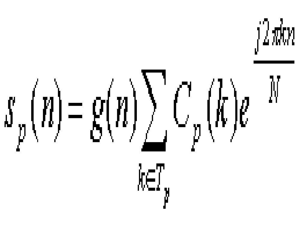
삭제delete
여기서, g(n)은 이산 파형 성형 필터를 나타내며, C p (k)는 훈련신호의 생성에 사용되는 주파수 축 신호열을 의미한다. 주파수 신호열은 시간 영역에서 관찰한 훈련신호의 첨두대평균전력비(PAPR)가 충분히 작고 우수한 자기 상관 특성을 가지도록 선택된다. Here, g (n) denotes a discrete waveform shaping filter, and C p (k) denotes a frequency axis signal sequence used for generating a training signal. The frequency signal sequence is chosen so that the peak-to-average power ratio (PAPR) of the training signal observed in the time domain is sufficiently small and has good autocorrelation characteristics.
주파수 동기 추정이 가능하게 하기 위해서, p번째 사용자의 프리엠블은 훈련신호와 N 샘플 지연된 훈련 신호의 반복 신호열에 의해 다음 수학식 4와 같이 구성된다.
![]()
![]()
삭제delete
도 2는 OFDMA 시스템의 역방향 프리엠블 신호 전송 과정을 설명하기 위한 도면으로 p번째 사용자 단말과 q번째 사용자 단말은 순방향 링크를 통해 기지국으로부터 전송되는 시간 참조 신호를 수신하고 이 참조 신호에 시간 및 주파수 동기를 맞춘다. 각각의 사용자 단말은 톤 자신의 톤 집합을 이용하여 생성시킨 프리엠블 신호를 설정된 시간 및 주파수 동기에 의해 보정한 후 송신한다. 이 경우, 상향 링크에서의 사용자 신호의 초기 접속시 시간 동기 부정확성은 대략 사용자 전송 지연의 두 배 정도이다. 각 사용자 단말에서 송신된 프리엠블 신호는 각각 서로 다른 다중 경로 채널, 시간 및 주파수 동기 오차를 포함하게 되므로 기지국에서 수신하는 프리엠블 신호는 다음 수학식 5와 같이 표현된다.
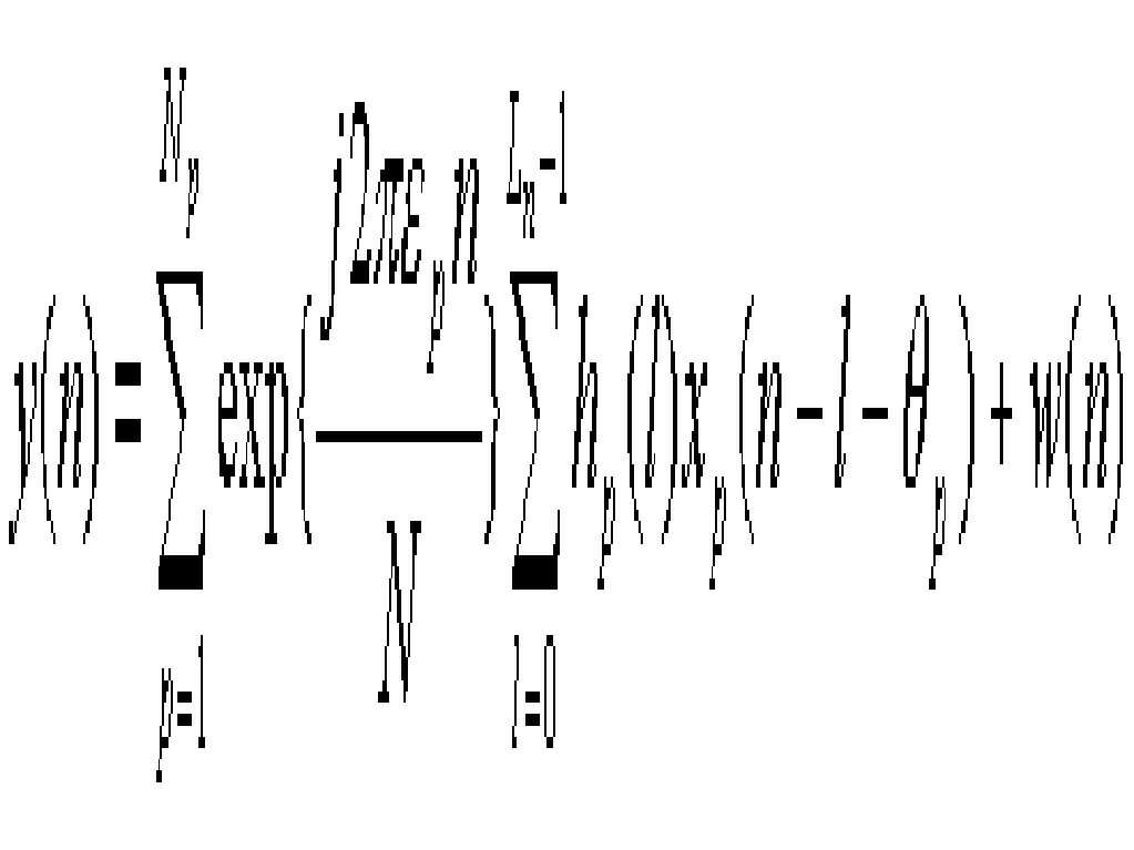
여기서, hp(l)은 p번째 사용자의 다중경로 채널에 대한 임펄스 응답을, w(n)은 백색 가우시안 잡음을 나타내고, ![]()
![]()
Where h p (l) represents the impulse response for the multipath channel of the p-th user, w (n) represents the white Gaussian noise, ![]()
![]()
삭제delete
삭제delete
이와 같은 방법으로 수신된 프리엠블 신호를 이용하여 기지국은 각 사용자의 시간 및 주파수 동기 오차를 추정한다. Using the preamble signal received in this way, the base station estimates the time and frequency synchronization error of each user.
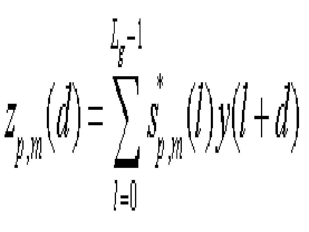
도 3은 본 발명의 바람직한 실시예에 따른 기지국 수신기의 시간/주파수 동기 오차 추정 장치를 보인 도면이다.3 is a diagram illustrating an apparatus for estimating time / frequency synchronization error of a base station receiver according to a preferred embodiment of the present invention.
도 3에서 보는 바와 같이, 상기 시간/주파수 동기 오차 추정 장치는 수신된 프리엠블 신호 y(n)를 N샘플 지연시키는 지연기(301), 상기 프리엠블 신호 y(n)에 p번째 사용자의 훈련 신호 sp(n)를 곱하는 제1믹서(302)와 상기 지연기(301)의 출력신호에 p번째 사용자의 훈련 신호 sp(n)를 곱하는 제2믹서(303), 상기 제1믹서(302)와 제2믹서(303)로부터 출력되는 각각의 출력신호의 무빙 섬 (moving sum)을 계산하는 제1 및 제2 무빙 섬 유닛(304, 305), 상기 제1무빙 섬 유닛 (304)의 출력 신호에 복소공액을 취하는 복소공액화기(306), 상기 복소공액화기(306)의 출력과 상기 제2 무빙 섬 유닛 (305)의 출력을 곱하는 시간 동기 매트릭을 생성하는 제3믹서(307), 상기 시간동기 매트릭이 최대가 되는 시점을 검출하여 시간 동기 오차를 구하는 최대값 검출기(308), 상기 최대값 검출기(308)에 의해 구해진 시간 동기 오차를 이용하여 주파수 동기 오차를 구하는 연산기(309)로 구성된다. As shown in FIG. 3, the apparatus for estimating the time / frequency synchronization error includes a
p번째 사용자의 훈련 신호를 위해 Nm개의 부대역을 이용하는 경우, 해당 사용자 단말에 대한 상관기의 출력과 시간동기 메트릭은 다음 수학식 6 및 수학식 7과 같이 나타낼 수 있다.
삭제delete
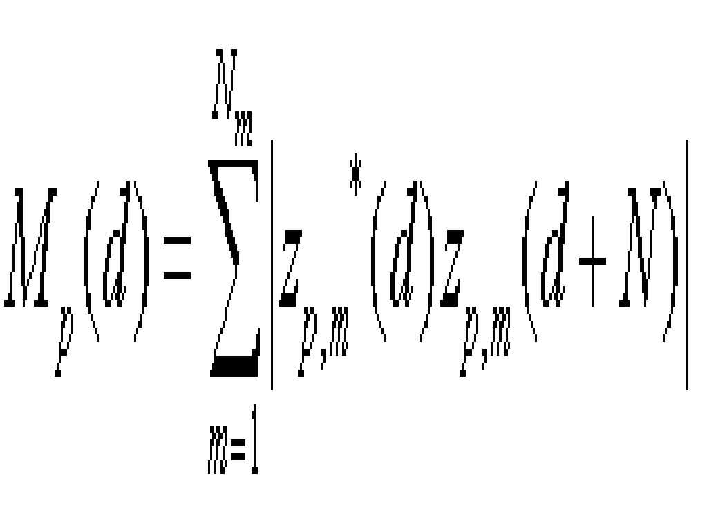
상기 수학식 7로부터 p번째 사용자 단말의 시간 및 주파수 동기 오차는 각각 수학식 8 및 수학식 9와 같이 구해진다.The time and frequency synchronization error of the p-th user terminal from the equation (7) is obtained as shown in equations (8) and (9), respectively.
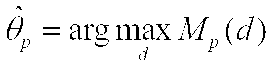

삭제delete
훈련 신호열 ![]()
![]()
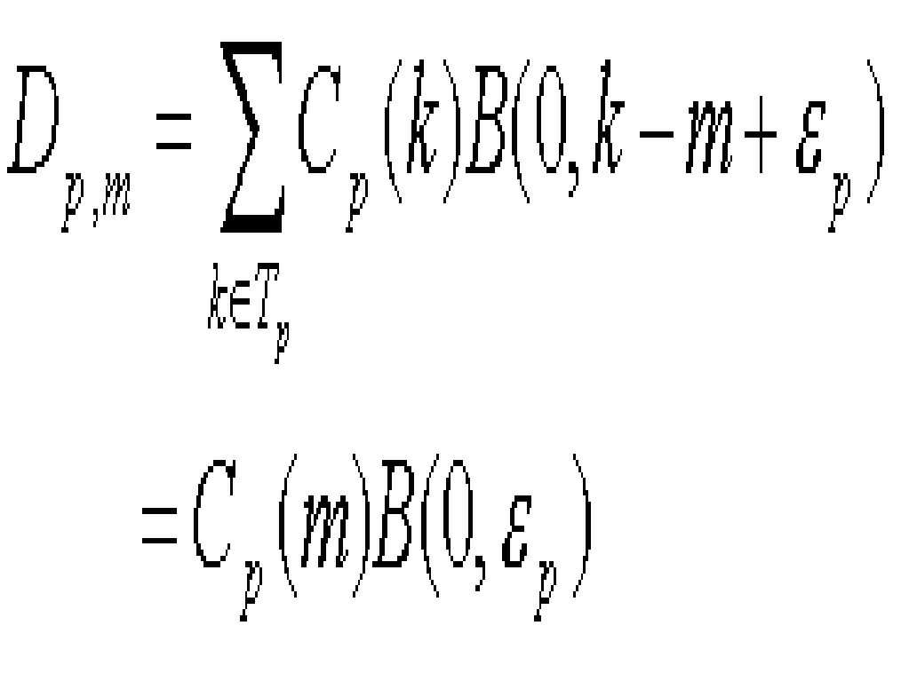
![]()
![]()
삭제delete
![]()
![]()
삭제delete
이렇게 정의된 B(Δt , Δf )를 이용하면, 사용자 단말 q에 의해 발생한 간섭은 다음 수학식 12과 같이 간단하게 표현된다. With this definition of B (Δ t, Δ f) , interference caused by the user terminal q is simply expressed as equation (12).
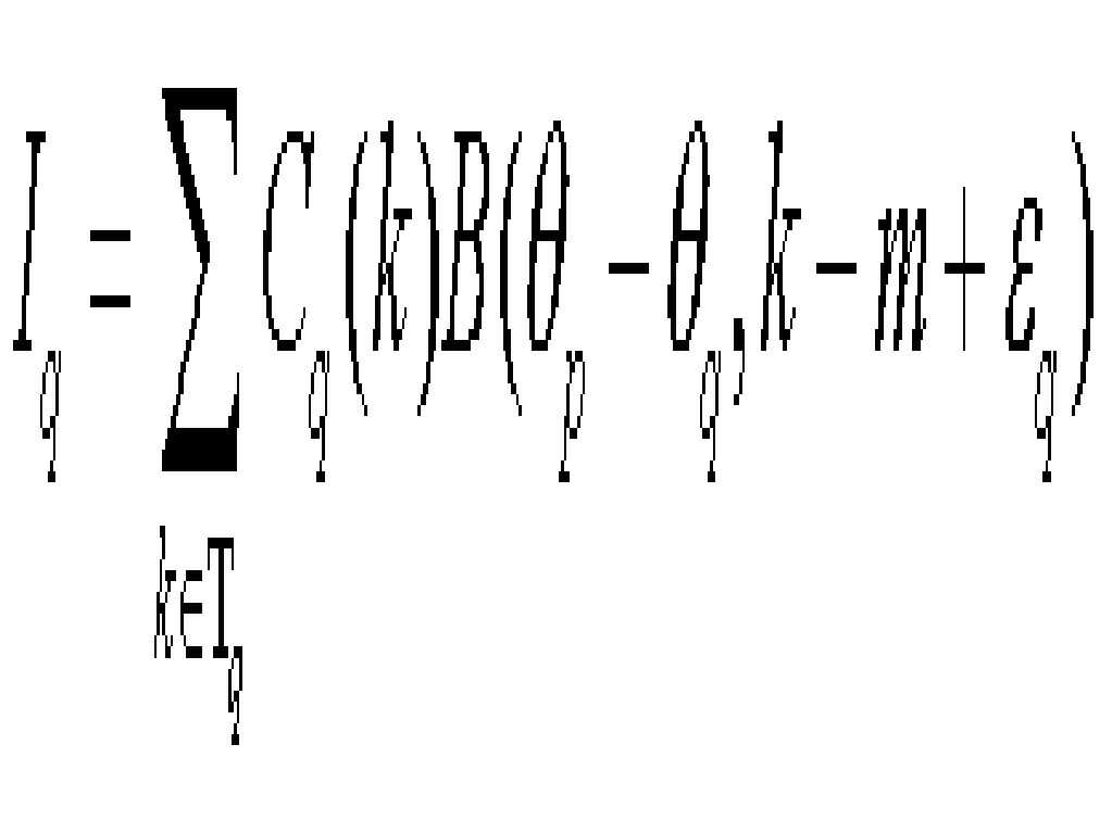
수학식 12은 사용자 단말 p와 q의 시간 오차에 따른 k번째 톤에 의한 누설 전력을 나타낸다.
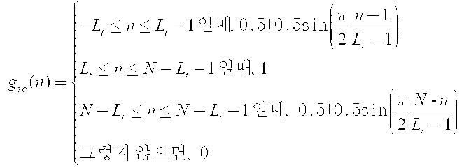
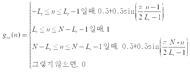
따라서 다른 사용자에 의한 간섭을 완화시키기 위해 중첩되지 않는 파형 성형 필터를 사용하여야 한다. 이러한 파형 성형 필터로서 본 발명의 바람직한 실시예에서는 시간축 레이즈드 코사인 (RC) 필터를 사용한다.Therefore, non-overlapping waveform shaping filters should be used to mitigate interference by other users. As such a waveform shaping filter, a preferred embodiment of the present invention uses a time-axis raised cosine (RC) filter.
상기 RC 필터의 시간 응답 특성은 다음 수학식 13과 같다.The time response characteristic of the RC filter is expressed by Equation 13.

여기서, ![]()
![]()
![]()
![]()
![]()
![]()
도 4는 본 발명의 바람직한 실시예에 따른 파형 성형 필터에 의한 주파수 응답 변화를 보인 그래프이다. 도 4에서 보는 바와 같이, ![]()
![]()
도 3에서 보여지는 훈련 신호열을 이용한 상관기의 성능을 평가하기 위해서는 주파수 선택적 채널을 가정한다. 채널 응답에 비해 심볼의 길이가 충분히 길어서 심볼간 간섭이 충분히 작다고 가정하면, 메트릭에서의 신호성분은 다음 수학식 14와 같이 근사화해서 나타낼 수 있다.
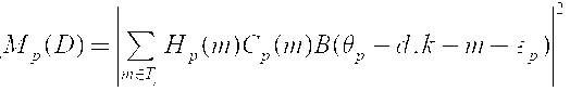
여기서, ![]()
![]()
![]()
here, ![]()
![]()
![]()
삭제delete
삭제delete
도 5a 및 도 5b는 각각 파형 성형 필터를 적용하지 않은 경우와 적용한 경우의 시간 동기 오차에 따른 누설 전력을 비교한 그래프로서 파형 성형 필터를 적용한 경우 시간 동기 오차가 발생했을 때에도 상관기 출력에서의 전력 누설이 차단되는 것을 확인할 수 있다. 따라서, 이러한 파형 성형 필터를 이용하면 시간축에서의 상관기를 이용하여 부대역간 간섭을 충분히 작게 유지하면서도 시간 동기의 획득이 가능하게 된다. 5A and 5B are graphs comparing the leakage power according to the time synchronization error when the waveform shaping filter is not applied and the power shaping at the correlator output even when a time synchronization error occurs when the waveform shaping filter is applied. You can see that this is blocked. Therefore, by using such a waveform shaping filter, it is possible to obtain time synchronization while keeping the interference between subbands sufficiently small using a correlator on the time axis.
도 6은 본 발명에 따른 시간/주파수 동기 추정 방법과 종래의 푸리에 변환 이후의 위상변화 관찰을 통한 동기 추정 방법의 성능 비교 실험 결과를 보인 그래프이다. 6 is a graph showing the results of performance comparison experiments of the time / frequency synchronization estimation method according to the present invention and the conventional synchronization estimation method by observing the phase change after the Fourier transform.
본 발명에 따른 시간/주파수 동기 방법의 성능 실험 환경은 다음과 같다.The performance test environment of the time / frequency synchronization method according to the present invention is as follows.
전체 부반송파의 개수(FFT의 크기)가 512이고 전체 부반송파 중 대역의 바깥쪽 경계에 해당하는 양쪽 끝 132개의 부반송파는 펄스 성형을 위해서 사용되지 않 고 남겨진다. 따라서, 가용한 톤의 개수는 380이다. 각 사용자의 상호 배타적인 16개의 톤을 사용한다고 가정하였다. 이러한 할당 방법에 의해 가용한 부대역의 개수는 23개이다. 채널환경은 64탭을 가지는 레일레이 페이딩 채널 환경이고, 각 사용자의 주파수 오차는 소수배(부반송파 간격의 절반: ![]()
![]()
도 6에서 보는 바와 같이, 본 발명에 따른 시간/주파수 동기 추정 방법의 경우 종래의 동기 추정 방법에 비해 시간/주파수 신호대잡음비(SNR)에 대한 시간 동기 오류가 현저히 낮음을 알 수 있다. As shown in FIG. 6, it can be seen that the time / frequency synchronization estimation method according to the present invention has a significantly lower time synchronization error with respect to time / frequency signal-to-noise ratio (SNR) than the conventional synchronization estimation method.
상기한 바와 같이 본 발명에 따른 시간 및 주파수 동기화 방법에서는 직교성 유지를 위한 과도한 순환 보호구간을 필요로 하지 않기 때문에 우수한 대역폭 효율을 제공한다.As described above, the time and frequency synchronization method according to the present invention does not require excessive cyclic guard interval for maintaining orthogonality, thereby providing excellent bandwidth efficiency.
또한, 수신단에서 동기 오차를 추정하기 위해 시간축 상관기를 사용하기 때문에 주파수 오차에 대해 강건한(Robust) 추정기의 구현이 가능하다.In addition, since the time-base correlator is used to estimate the synchronization error at the receiving end, it is possible to implement a robust estimator for the frequency error.
또한, 대역폭 효율을 일정하게 유지할 경우, 단일 사용자에 대해 다수의 부대역을 할당할 수 있기 때문에 주파수 다이버시티 성능이 향상된다. In addition, if bandwidth efficiency is kept constant, multiple subbands can be assigned to a single user, thereby improving frequency diversity performance.
Claims (12)
Priority Applications (1)
| Application Number | Priority Date | Filing Date | Title |
|---|---|---|---|
| KR1020040006932A KR100594094B1 (en) | 2004-02-03 | 2004-02-03 | Time and Frequency Synchronization Method for Reverse Link in Orthogonal Frequency Division Multiple Access Based Mobile Communication System |
Applications Claiming Priority (1)
| Application Number | Priority Date | Filing Date | Title |
|---|---|---|---|
| KR1020040006932A KR100594094B1 (en) | 2004-02-03 | 2004-02-03 | Time and Frequency Synchronization Method for Reverse Link in Orthogonal Frequency Division Multiple Access Based Mobile Communication System |
Publications (2)
| Publication Number | Publication Date |
|---|---|
| KR20050078859A KR20050078859A (en) | 2005-08-08 |
| KR100594094B1 true KR100594094B1 (en) | 2006-06-30 |
Family
ID=37265925
Family Applications (1)
| Application Number | Title | Priority Date | Filing Date |
|---|---|---|---|
| KR1020040006932A Expired - Fee Related KR100594094B1 (en) | 2004-02-03 | 2004-02-03 | Time and Frequency Synchronization Method for Reverse Link in Orthogonal Frequency Division Multiple Access Based Mobile Communication System |
Country Status (1)
| Country | Link |
|---|---|
| KR (1) | KR100594094B1 (en) |
Families Citing this family (2)
| Publication number | Priority date | Publication date | Assignee | Title |
|---|---|---|---|---|
| KR100746553B1 (en) * | 2005-12-09 | 2007-08-06 | 한국전자통신연구원 | Apparatus and method for CFO aided timing offset tracking for OFDM system |
| US7583654B2 (en) * | 2005-12-28 | 2009-09-01 | Honeywell International Inc. | Sub-frame synchronized multiplexing |
Citations (4)
| Publication number | Priority date | Publication date | Assignee | Title |
|---|---|---|---|---|
| US20020118666A1 (en) | 2000-11-15 | 2002-08-29 | Stanwood Kenneth L. | Framing for an adaptive modulation communication system |
| US20020159413A1 (en) | 2001-02-26 | 2002-10-31 | Clarion Co., Ltd. | Wireless communication network system |
| US6643281B1 (en) | 1998-03-05 | 2003-11-04 | At&T Wireless Services, Inc. | Synchronization preamble method for OFDM waveforms in a communications system |
| KR20040069325A (en) * | 2001-12-14 | 2004-08-05 | 보오슈 앤드 롬 인코포레이팃드 | Apparatus and the associated methods for calibrating a wavefront sensor |
-
2004
- 2004-02-03 KR KR1020040006932A patent/KR100594094B1/en not_active Expired - Fee Related
Patent Citations (4)
| Publication number | Priority date | Publication date | Assignee | Title |
|---|---|---|---|---|
| US6643281B1 (en) | 1998-03-05 | 2003-11-04 | At&T Wireless Services, Inc. | Synchronization preamble method for OFDM waveforms in a communications system |
| US20020118666A1 (en) | 2000-11-15 | 2002-08-29 | Stanwood Kenneth L. | Framing for an adaptive modulation communication system |
| US20020159413A1 (en) | 2001-02-26 | 2002-10-31 | Clarion Co., Ltd. | Wireless communication network system |
| KR20040069325A (en) * | 2001-12-14 | 2004-08-05 | 보오슈 앤드 롬 인코포레이팃드 | Apparatus and the associated methods for calibrating a wavefront sensor |
Non-Patent Citations (1)
| Title |
|---|
| 1020040006932 - 571504 |
Also Published As
| Publication number | Publication date |
|---|---|
| KR20050078859A (en) | 2005-08-08 |
Similar Documents
| Publication | Publication Date | Title |
|---|---|---|
| US7599327B2 (en) | Method and apparatus for accessing a wireless communication system | |
| KR100865251B1 (en) | Method and apparatus for pilot signal transmission | |
| JP5096373B2 (en) | Method and system for synchronization in a communication system | |
| EP1959625B1 (en) | Receiver apparatus for detecting narrowband interference in a multi-carrier receive signal | |
| JP4900447B2 (en) | Transmitting apparatus and transmitting method | |
| EP1555761A1 (en) | Apparatus and method for estimating interference and noise in a communication system | |
| US20090225741A1 (en) | Wireless system using a new type of preamble for a burst frame | |
| JP2012213151A (en) | Multicarrier signal processing using filter bank for synchronization with preamble | |
| JP4644978B2 (en) | OFDM communication system, OFDM communication method, and OFDM communication apparatus | |
| KR100798968B1 (en) | Method and apparatus for transmitting and receiving pilot signal in orthogonal division multiple access system | |
| KR20050101253A (en) | Method and device for searching cell in ofdma systems | |
| US20190173640A1 (en) | Transmitter and method for formatting transmit data into a frame structure | |
| CN104836770B (en) | It is a kind of based on related average and adding window timing estimation method | |
| Boumard et al. | Robust and accurate frequency and timing synchronization using chirp signals | |
| CN101521548B (en) | Noise power estimation apparatus and method | |
| EP1555783A2 (en) | Pilot-based channel estimation method for MC-CDMA system using frequency interleaving | |
| KR100594094B1 (en) | Time and Frequency Synchronization Method for Reverse Link in Orthogonal Frequency Division Multiple Access Based Mobile Communication System | |
| KR100678193B1 (en) | Apparatus and Method for Estimating Interference and Noise in Communication Systems | |
| TWI396415B (en) | Channel length estimation method and estimator of orthogonal frequency division multiplexing system | |
| CN101001232A (en) | Sending method and system for synchronous signal | |
| KR20080042421A (en) | Orthogonal Frequency Division Multiplexing System Using Preamble Symbols, Its Generation Method, and Timing / Frequency Synchronization Acquisition Method | |
| JP2004304473A (en) | Multicarrier receiving apparatus and line compensation method | |
| TWI399062B (en) | Interference estimating apparatus, method and apparatus for determining guard interval length and bit loading | |
| KR100861595B1 (en) | Multi-User Detection Method in Receiver in Multi-Carrier Code Division Multiple Access System | |
| KR20070076372A (en) | Device for generating downlink signal and data restoration method of cellular system |
Legal Events
| Date | Code | Title | Description |
|---|---|---|---|
| A201 | Request for examination | ||
| PA0109 | Patent application |
St.27 status event code: A-0-1-A10-A12-nap-PA0109 |
|
| PA0201 | Request for examination |
St.27 status event code: A-1-2-D10-D11-exm-PA0201 |
|
| P11-X000 | Amendment of application requested |
St.27 status event code: A-2-2-P10-P11-nap-X000 |
|
| P13-X000 | Application amended |
St.27 status event code: A-2-2-P10-P13-nap-X000 |
|
| PN2301 | Change of applicant |
St.27 status event code: A-3-3-R10-R13-asn-PN2301 St.27 status event code: A-3-3-R10-R11-asn-PN2301 |
|
| PN2301 | Change of applicant |
St.27 status event code: A-3-3-R10-R13-asn-PN2301 St.27 status event code: A-3-3-R10-R11-asn-PN2301 |
|
| PG1501 | Laying open of application |
St.27 status event code: A-1-1-Q10-Q12-nap-PG1501 |
|
| D13-X000 | Search requested |
St.27 status event code: A-1-2-D10-D13-srh-X000 |
|
| D14-X000 | Search report completed |
St.27 status event code: A-1-2-D10-D14-srh-X000 |
|
| E902 | Notification of reason for refusal | ||
| PE0902 | Notice of grounds for rejection |
St.27 status event code: A-1-2-D10-D21-exm-PE0902 |
|
| P11-X000 | Amendment of application requested |
St.27 status event code: A-2-2-P10-P11-nap-X000 |
|
| P13-X000 | Application amended |
St.27 status event code: A-2-2-P10-P13-nap-X000 |
|
| E701 | Decision to grant or registration of patent right | ||
| PE0701 | Decision of registration |
St.27 status event code: A-1-2-D10-D22-exm-PE0701 |
|
| GRNT | Written decision to grant | ||
| PR0701 | Registration of establishment |
St.27 status event code: A-2-4-F10-F11-exm-PR0701 |
|
| PR1002 | Payment of registration fee |
St.27 status event code: A-2-2-U10-U11-oth-PR1002 Fee payment year number: 1 |
|
| PG1601 | Publication of registration |
St.27 status event code: A-4-4-Q10-Q13-nap-PG1601 |
|
| PR1001 | Payment of annual fee |
St.27 status event code: A-4-4-U10-U11-oth-PR1001 Fee payment year number: 4 |
|
| PR1001 | Payment of annual fee |
St.27 status event code: A-4-4-U10-U11-oth-PR1001 Fee payment year number: 5 |
|
| PN2301 | Change of applicant |
St.27 status event code: A-5-5-R10-R13-asn-PN2301 St.27 status event code: A-5-5-R10-R11-asn-PN2301 |
|
| PN2301 | Change of applicant |
St.27 status event code: A-5-5-R10-R13-asn-PN2301 St.27 status event code: A-5-5-R10-R11-asn-PN2301 |
|
| PR1001 | Payment of annual fee |
St.27 status event code: A-4-4-U10-U11-oth-PR1001 Fee payment year number: 6 |
|
| PR1001 | Payment of annual fee |
St.27 status event code: A-4-4-U10-U11-oth-PR1001 Fee payment year number: 7 |
|
| R18-X000 | Changes to party contact information recorded |
St.27 status event code: A-5-5-R10-R18-oth-X000 |
|
| FPAY | Annual fee payment |
Payment date: 20130530 Year of fee payment: 8 |
|
| PR1001 | Payment of annual fee |
St.27 status event code: A-4-4-U10-U11-oth-PR1001 Fee payment year number: 8 |
|
| FPAY | Annual fee payment |
Payment date: 20140529 Year of fee payment: 9 |
|
| PR1001 | Payment of annual fee |
St.27 status event code: A-4-4-U10-U11-oth-PR1001 Fee payment year number: 9 |
|
| FPAY | Annual fee payment |
Payment date: 20150528 Year of fee payment: 10 |
|
| PR1001 | Payment of annual fee |
St.27 status event code: A-4-4-U10-U11-oth-PR1001 Fee payment year number: 10 |
|
| FPAY | Annual fee payment |
Payment date: 20160530 Year of fee payment: 11 |
|
| PR1001 | Payment of annual fee |
St.27 status event code: A-4-4-U10-U11-oth-PR1001 Fee payment year number: 11 |
|
| FPAY | Annual fee payment |
Payment date: 20170529 Year of fee payment: 12 |
|
| P22-X000 | Classification modified |
St.27 status event code: A-4-4-P10-P22-nap-X000 |
|
| PR1001 | Payment of annual fee |
St.27 status event code: A-4-4-U10-U11-oth-PR1001 Fee payment year number: 12 |
|
| FPAY | Annual fee payment |
Payment date: 20180530 Year of fee payment: 13 |
|
| PR1001 | Payment of annual fee |
St.27 status event code: A-4-4-U10-U11-oth-PR1001 Fee payment year number: 13 |
|
| PC1903 | Unpaid annual fee |
St.27 status event code: A-4-4-U10-U13-oth-PC1903 Not in force date: 20190621 Payment event data comment text: Termination Category : DEFAULT_OF_REGISTRATION_FEE |
|
| PC1903 | Unpaid annual fee |
St.27 status event code: N-4-6-H10-H13-oth-PC1903 Ip right cessation event data comment text: Termination Category : DEFAULT_OF_REGISTRATION_FEE Not in force date: 20190621 |
|
| R18-X000 | Changes to party contact information recorded |
St.27 status event code: A-5-5-R10-R18-oth-X000 |
|
| P22-X000 | Classification modified |
St.27 status event code: A-4-4-P10-P22-nap-X000 |