KR100580074B1 - Battery pack removable device of mobile communication terminal - Google Patents
Battery pack removable device of mobile communication terminal Download PDFInfo
- Publication number
- KR100580074B1 KR100580074B1 KR1020030089713A KR20030089713A KR100580074B1 KR 100580074 B1 KR100580074 B1 KR 100580074B1 KR 1020030089713 A KR1020030089713 A KR 1020030089713A KR 20030089713 A KR20030089713 A KR 20030089713A KR 100580074 B1 KR100580074 B1 KR 100580074B1
- Authority
- KR
- South Korea
- Prior art keywords
- battery pack
- push button
- main body
- battery
- operating member
- Prior art date
- Legal status (The legal status is an assumption and is not a legal conclusion. Google has not performed a legal analysis and makes no representation as to the accuracy of the status listed.)
- Expired - Fee Related
Links
Images


Classifications
-
- H—ELECTRICITY
- H04—ELECTRIC COMMUNICATION TECHNIQUE
- H04B—TRANSMISSION
- H04B1/00—Details of transmission systems, not covered by a single one of groups H04B3/00 - H04B13/00; Details of transmission systems not characterised by the medium used for transmission
- H04B1/38—Transceivers, i.e. devices in which transmitter and receiver form a structural unit and in which at least one part is used for functions of transmitting and receiving
- H04B1/40—Circuits
-
- H—ELECTRICITY
- H01—ELECTRIC ELEMENTS
- H01M—PROCESSES OR MEANS, e.g. BATTERIES, FOR THE DIRECT CONVERSION OF CHEMICAL ENERGY INTO ELECTRICAL ENERGY
- H01M50/00—Constructional details or processes of manufacture of the non-active parts of electrochemical cells other than fuel cells, e.g. hybrid cells
- H01M50/20—Mountings; Secondary casings or frames; Racks, modules or packs; Suspension devices; Shock absorbers; Transport or carrying devices; Holders
- H01M50/262—Mountings; Secondary casings or frames; Racks, modules or packs; Suspension devices; Shock absorbers; Transport or carrying devices; Holders with fastening means, e.g. locks
- H01M50/264—Mountings; Secondary casings or frames; Racks, modules or packs; Suspension devices; Shock absorbers; Transport or carrying devices; Holders with fastening means, e.g. locks for cells or batteries, e.g. straps, tie rods or peripheral frames
-
- H—ELECTRICITY
- H01—ELECTRIC ELEMENTS
- H01M—PROCESSES OR MEANS, e.g. BATTERIES, FOR THE DIRECT CONVERSION OF CHEMICAL ENERGY INTO ELECTRICAL ENERGY
- H01M50/00—Constructional details or processes of manufacture of the non-active parts of electrochemical cells other than fuel cells, e.g. hybrid cells
- H01M50/20—Mountings; Secondary casings or frames; Racks, modules or packs; Suspension devices; Shock absorbers; Transport or carrying devices; Holders
- H01M50/202—Casings or frames around the primary casing of a single cell or a single battery
-
- Y—GENERAL TAGGING OF NEW TECHNOLOGICAL DEVELOPMENTS; GENERAL TAGGING OF CROSS-SECTIONAL TECHNOLOGIES SPANNING OVER SEVERAL SECTIONS OF THE IPC; TECHNICAL SUBJECTS COVERED BY FORMER USPC CROSS-REFERENCE ART COLLECTIONS [XRACs] AND DIGESTS
- Y02—TECHNOLOGIES OR APPLICATIONS FOR MITIGATION OR ADAPTATION AGAINST CLIMATE CHANGE
- Y02E—REDUCTION OF GREENHOUSE GAS [GHG] EMISSIONS, RELATED TO ENERGY GENERATION, TRANSMISSION OR DISTRIBUTION
- Y02E60/00—Enabling technologies; Technologies with a potential or indirect contribution to GHG emissions mitigation
- Y02E60/10—Energy storage using batteries
Landscapes
- Chemical & Material Sciences (AREA)
- Chemical Kinetics & Catalysis (AREA)
- Electrochemistry (AREA)
- General Chemical & Material Sciences (AREA)
- Engineering & Computer Science (AREA)
- Computer Networks & Wireless Communication (AREA)
- Signal Processing (AREA)
- Battery Mounting, Suspending (AREA)
Abstract
본 발명은 간단히 누름버튼을 누름에 따라 배터리팩이 본체에서 이탈되도록 한 이동통신 단말기의 배터리 착탈장치에 관한 것으로, 그 구성은 본체부의 배터리장착부에 걸림홈이 형성된 배터리팩이 구비되고, 상기 배터리팩은 잠금부에 의해 배터리장착부에 고정 및 이탈되도록 구성된 이동통신 단말기에 있어서, 상기 잠금부는, 상기 본체부의 수직방향으로 구비되는 누름버튼과; 상기 누름버튼을 탄력지지하는 탄성수단과; 상기 누름버튼의 하부에서 상기 배터리팩이 상기 배터리장착부에 고정 및 이탈되도록 하는 작동부재와; 상기 누름버튼의 상하운동에 따라 상기 작동부재가 회전하도록 하는 회전수단;으로 구성된다.The present invention relates to a battery detachable device of a mobile communication terminal which is to be detached from the main body by simply pressing a push button, the configuration is provided with a battery pack having a locking groove formed in the battery mounting portion of the main body, the battery pack A mobile communication terminal configured to be fixed to and detached from a battery mounting unit by a lock unit, wherein the lock unit comprises: a push button provided in a vertical direction of the main body unit; Elastic means for elastically supporting the push button; An operation member configured to fix and detach the battery pack from the lower part of the push button; Rotating means for rotating the operation member in accordance with the vertical movement of the push button.
이에 따라, 배터리팩 교환시에 배터리팩을 본체부에서 더욱 간편하게 분리할 수 있게 될 뿐만 아니라, 배터리팩의 분리 시에 배터리팩을 놓쳐 배터리팩이 파손되는 것을 미연에 방지하는 효과를 가진다.Accordingly, the battery pack can be more easily removed from the main body when the battery pack is replaced, and the battery pack can be missed when the battery pack is removed, thereby preventing the battery pack from being damaged.
이동통신 단말기, 배터리팩, 누름버튼, 회전수단Mobile communication terminal, battery pack, push button, rotating means
Description
도 1은 본 발명의 일 실시 예를 보인 분해사시도,1 is an exploded perspective view showing an embodiment of the present invention,
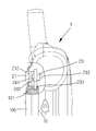
도 2는 도 1에 따른 요부를 확대한 측면도,Figure 2 is an enlarged side view of the main portion according to FIG.
도 3은 본 발명에 따른 배터리팩의 고정상태를 보인 것으로서,3 is a view showing a fixed state of the battery pack according to the present invention,
도 3a는 배터리팩이 장착된 이동통신 단말기의 후면도, 3a is a rear view of a mobile communication terminal equipped with a battery pack,
도 3b는 도 3a에 따른 측단면도, 3b is a side cross-sectional view according to FIG. 3a,
도 4는 본 발명에 따른 배터리팩의 분리상태를 보인 것으로서,4 is a view showing a detached state of a battery pack according to the present invention,
도 4a는 배터리팩의 이탈상태를 보인 이동통신 단말기의 후면도, Figure 4a is a rear view of the mobile communication terminal showing the detached state of the battery pack,
도 4b는 도 4a에 따른 측단면도, 4b is a side cross-sectional view according to FIG. 4a,
도 5는 종래 배터리팩의 장착상태를 보인 휴대폰의 후면사시도.Figure 5 is a rear perspective view of a mobile phone showing a state of mounting of a conventional battery pack.
※ 도면의 주요 부분에 대한 부호의 설명※ Explanation of codes for main parts of drawing
1 : 본체부1: main body
10 : 배터리장착부10: battery compartment
20 : 잠금부20: locking part
21 : 누름버튼 21: push button
211 : 가이드돌기 212 : 스토퍼 211: guide protrusion 212: stopper
22 : 탄성수단 22: elastic means
23 : 작동부재 23: operating member
231 : 걸림턱 232 : 이탈돌기 231: jam jaw 232: escape protrusion
233 : 회전축 234 : 가이드축 233: rotating shaft 234: guide shaft
24 : 회전수단 24: rotation means
241 : 승강경사면 242 : 회전경사면 241: lifting slope 242: rotation slope
100 : 배터리팩100: battery pack
101 : 걸림홈 101: hanging groove
본 발명은 이동통신 단말기의 배터리팩 착탈장치에 관한 것으로, 더욱 상세하게는 간단히 누름버튼을 누름에 따라 배터리팩이 본체에서 이탈되도록 한 이동통신 단말기의 배터리팩 착탈장치에 관한 것이다.The present invention relates to a battery pack detachable device of a mobile communication terminal, and more particularly, to a battery pack detachable device of a mobile communication terminal to be detached from the main body by simply pressing a push button.
일반적으로 이동통신 단말기는 사용자가 시간과 장소에 구애받지 않고 자유롭게 무선통신을 할 수 있도록 개발된 첨단 이동통신수단의 일종으로 휴대폰, PDA등이 개발되어지고 있으며, 특히 휴대폰은 대중의 기호에 따라 초기의 무전기형으로부터 플립형, 폴더형 등 다양한 구조의 단말기가 출시되어 있으며, 근래에는 무선인터넷 접속이 가능함은 물론 디지털카메라등의 보조장치가 구비된 다양한 기능의 이동통신 단말기이 출시되고 있는 실정이다.In general, a mobile communication terminal is a kind of high-tech mobile communication means developed to allow users to freely communicate wirelessly regardless of time and place, and mobile phones and PDAs are being developed. Various types of terminals such as flip type and flip type have been released. In recent years, mobile communication terminals having various functions including wireless cameras as well as auxiliary devices such as digital cameras have been released.
이러한 이동통신 단말기에 필수적으로 구비되는 것이 배터리팩인데, 배터리팩은 휴대중에 배터리가 방전되더라도 용이하게 사용하고, 오랜 사용에 의해 수명이 다한 배터리를 새 제품으로 교체하여 사용할 수 있도록 착탈식으로 형성되고 있다.Essentially provided in such a mobile communication terminal is a battery pack, the battery pack is formed to be easily removable even when the battery is discharged while carrying, and to replace the battery that is at the end of life by a long time to use a new product. .
특히, 휴대폰의 경우에는 본체의 외측면에 고정되어 교체가 더욱 용이하도록 하고 있는데, 도 5에서 보인 바와 같이 종래의 배터리팩(200)은 본체(300)의 일측면에 배터리장착부(301)를 형성하고, 배터리장착부(301)의 일측에 배터리팩(200)을 고정 및 이탈시키는 잠금부(400)를 형성하여 배터리팩(200)이 사용중에 본체(300)에서 이탈되지 않으면서 안정적으로 전원을 공급하도록 하고 있다.In particular, in the case of a mobile phone is fixed to the outer side of the main body to make it easier to replace, as shown in Figure 5, the
그러나, 종래의 배터리팩을 본체와 분리하기 위해서는 한손으로 잠금부를 슬라이딩시켜 고정을 해제하고 다른 한손으로는 배터리팩을 분리해야 하는 관계로, 본체에서 배터리팩을 분리하는 과정이 번거롭고 불편했으며, 배터리팩을 분리하는 과정에서 배터리팩을 떨어뜨려 배터리팩이 파손되는 경우도 발생하였다.However, in order to separate the conventional battery pack from the main body, the locking part needs to be released by sliding with one hand to release the battery pack with the other hand, and the process of separating the battery pack from the main body was cumbersome and inconvenient. In the process of removing the battery pack was dropped, the battery pack was also broken.
이에, 본 발명은 상기와 같은 종래의 제반 문제점을 해소하기 위하여 안출한 것으로, 그 목적은 간단히 누름버튼을 누름에 따라 배터리팩이 본체에서 이탈되도록 함에 있다.Accordingly, the present invention has been made in order to solve the conventional problems as described above, the object is that the battery pack is separated from the main body by simply pressing the push button.
또한, 본 발명의 목적은 누름버튼이 상하방향으로만 원활히 작동하도록 함에 있다.In addition, an object of the present invention is to push button is operated smoothly only in the vertical direction.
또한, 본 발명의 목적은 누름버튼의 상하방향 작동에 의해 작동부재가 원활 히 회전하도록 함에 있다.In addition, an object of the present invention is to allow the operating member to rotate smoothly by the vertical operation of the push button.
또한, 본 발명의 목적은 작동부재가 회전된 후에 원위치로 정확히 복귀하도록 함에 있다.It is also an object of the present invention to accurately return to the original position after the operating member is rotated.
또한, 본 발명의 목적은 작동부재가 본체부에서 이탈되지 않고 회전되며, 배터리팩을 견고히 고정하도록 함에 있다.In addition, an object of the present invention is to rotate the operating member is not separated from the main body portion, to securely fix the battery pack.
또한, 본 발명의 목적은 배터리팩의 잠금 해제와 동시에 본체부에서 분리되며 이격되도록 함에 있다.In addition, an object of the present invention is to be separated from the body portion and at the same time apart from the unlocking of the battery pack.
상기와 같은 목적을 달성하기 위하여 본 발명은, 본체부의 배터리장착부에 걸림홈이 형성된 배터리팩이 구비되고, 상기 배터리팩은 잠금부에 의해 배터리장착부에 고정 및 이탈되도록 구성된 이동통신 단말기에 있어서, 상기 잠금부는, 상기 본체부의 수직방향으로 구비되는 누름버튼과; 상기 누름버튼을 탄력지지하는 탄성수단과; 상기 누름버튼의 하부에서 상기 배터리팩이 상기 배터리장착부에 고정 및 이탈되도록 하는 작동부재와; 상기 누름버튼의 상하운동에 따라 상기 작동부재가 회전하도록 하는 회전수단;으로 구성된 것을 특징으로 한다.In order to achieve the above object, the present invention, there is provided a battery pack having a locking groove formed in the battery mounting portion of the main body portion, the battery pack is a mobile communication terminal configured to be fixed and detached from the battery mounting portion by the lock, The locking unit includes a push button provided in the vertical direction of the main body; Elastic means for elastically supporting the push button; An operation member configured to fix and detach the battery pack from the lower part of the push button; And rotation means for rotating the operation member according to the up and down movement of the push button.
또한, 상기 누름버튼은, 측면에 수직방향의 가이드돌기가 형성되고, 상기 본체부의 내측면에 상기 가이드돌기와 대응되는 가이드홈이 형성된 것을 특징으로 한다.In addition, the push button, the guide projection in the vertical direction is formed on the side, characterized in that the guide groove corresponding to the guide projection is formed on the inner surface of the main body portion.
또한, 상기 회전수단은, 상기 누름버튼의 하면에 승강경사면이 형성되고, 상기 작동부재의 상면에 상기 승강경사면에 대응되는 회전경사면이 형성된 것을 특징으로 한다. In addition, the rotating means, the lifting slope is formed on the lower surface of the push button, the rotating inclined surface corresponding to the lifting slope is formed on the upper surface of the operation member.
또한, 상기 탄성수단은, 상기 작동부재의 외주면에 끼움되고, 일단이 본채부의 내측면을 지지하며, 타단이 작동부재에 고정된 비틀림스프링으로 구성된 것을 특징으로 한다.In addition, the elastic means, it is fitted to the outer circumferential surface of the actuating member, one end is characterized in that composed of a torsion spring fixed to the actuating member, the inner end of the main body portion.
또한, 상기 작동부재는, 하부에 본체부에 회전가능하게 끼움되는 회전축이 형성되고, 상부에 누름버튼이 이탈되지 않도록 삽입되는 가이드축이 형성되며, 일측으로 배터리팩의 걸림홈에 삽입 및 이탈되는 걸림턱이 형성된 것을 특징으로 한다.In addition, the operating member is formed in the lower portion of the rotating shaft is rotatably fitted to the main body portion, the guide shaft is inserted in the upper portion is inserted so as not to be separated, and inserted into and detached from the engaging groove of the battery pack to one side It is characterized in that the locking step is formed.
또한, 상기 작동부재의 하부 일측에 상기 걸림턱과 소정 각도 이격되어 돌출 형성되고, 작동부재의 회전에 따라 배터리장착부로 돌출되면서 배터리팩을 배터리장착부에서 이격시키는 이탈돌기가 형성된 것을 특징으로 한다.In addition, the lower one side of the operating member is projected to be spaced apart from the locking jaw by a predetermined angle, characterized in that the projecting to the battery mounting portion in accordance with the rotation of the operating member is formed a separation protrusion for separating the battery pack from the battery mounting portion.
이하, 본 발명의 바람직한 실시 예를 첨부된 도면을 참고로 하여 더욱 상세하게 설명하면 다음과 같다.Hereinafter, preferred embodiments of the present invention will be described in detail with reference to the accompanying drawings.
도 1은 본 발명의 일 실시 예를 보인 분해사시도이고, 도 2는 도 1에 따른 요부를 확대한 측면도로서, 도시된 바와 같이 본 발명은 이동통신 단말기의 본체부(1)에 배터리장착부(10)를 형성하고, 상기 배터리장착부(10)에 삽입되고 상부 측면에 형성된 걸림홈(101)에 의해 본체부(1)에 고정되어 이동통신 단말기에 전원을 공급하는 배터리팩(100)을 구비하며, 상기 배터리팩(100)을 본체부(1)에 고정 및 이탈되도록 하는 잠금부(20)를 형성하여 구성된다.1 is an exploded perspective view showing an embodiment of the present invention, Figure 2 is an enlarged side view of the main portion according to Figure 1, as shown in the present invention is a
상기 잠금부(20)는, 본체부(1)에 배터리장착부(10)와 근접되어 구비되고, 수 직방향으로 작동되는 누름버튼(21)과, 누름버튼(21)을 반복작동가능하도록 탄력 지지하는 탄성수단(22)과, 누름버튼(21)의 상하방향 작동에 의해 배터리팩(100)을 고정 및 이탈시키는 작동부재(23)와, 누름버튼(21)의 상하방향 작동에 의해 작동부재(23)가 회전운동하도록 하는 회전수단(24)으로 구성된다.The
상기 누름버튼(21)은, 본체부(1)의 외측으로 상단이 노출되어 사용자가 용이하게 누를 수 있도록 형성하고, 측면으로는 상하방향의 가이드돌기(211)를 형성하고, 누름버튼(21)이 장착되는 본체부(1)의 내측면에 가이드돌기(211)가 끼움되어 슬라이딩되는 가이드홈(미도시)을 형성하여 누름버튼(21)이 수직방향으로만 움직이도록 한다.The
또한, 상기 누름버튼(21)의 외주면에는 본체부(1)에 누름버튼(21)이 장착되면서 본체부(1)의 외부로 이탈되지 않도록 스토퍼(212)를 형성하는 것이 바람직하다.In addition, the
상기 탄성수단(22)은, 일단이 본체부(1)의 내측면을 지지하고, 타단이 후술되는 작동부재(23)에 고정되는 비틀림스프링으로 형성하여 작동부재(23)가 상시 배터리팩(100)을 고정하는 방향으로 회전하도록 하고, 또한, 누름버튼(21)이 상시 원위치로 복귀하도록 한다.The elastic means 22, one end supports the inner surface of the
상기 작동부재(23)는, 하부에 본체부(1)에 회전가능하게 끼움되는 회전축(233)을 형성하고, 일측으로는 회전하면서 배터리팩(100)의 걸림홈(101)에 끼움되어 배터리팩(100)을 본체부(1)에 고정 및 이탈되도록 하는 걸림턱(231)을 형성하여 누름버튼(21)의 상하 움직임에 따라 회전하면서 배터리팩(100)이 고정 및 이탈되도록 한다.The actuating
또한, 상기 걸림턱(231)의 하부에 소정 각도 이격되어 형성되고, 평상시에 본체부(1)의 내측에 수납되다가, 배터리팩(100)을 이탈시킬 때 작동부재(23)의 회전에 따라 배터리장착부(10)로 돌출되면서 배터리팩(100)의 하면을 밀어올려 배터리팩(100)을 본체부(1)와 이격시키는 이탈돌기(232)를 형성하여, 누름버튼(21)의 눌림에 의해 작동부재(23)가 회전하면서 배터리팩(100)의 고정이 해제됨과 동시에 본체부(1)에서 이격되도록 하여 배터리팩(100)의 분리가 더욱 용이하도록 하는 것도 바람직하다.In addition, it is formed below the
또한, 상기 작동부재(23)의 상부에는 누름버튼(21)이 끼움되는 가이드축(234)을 형성하여 누름버튼(21)과 작동부재(23)가 서로 원활이 작동하면서도 이탈되지 않도록 하는 것이 바람직하다.In addition, it is preferable to form a
상기 회전수단(24)은, 상기 누름버튼(21)의 하면에 승강경사면(241)을 형성하고, 상기 작동부재(23)의 상면에 승강경사면(241)과 대응되는 회전경사면(242)을 형성하여 구성된다.The rotating means 24, the lifting
이에 따라, 누름버튼(21)을 누르면 승강경사면(241)이 하강하면서 회전경사면(242)을 밀게되고, 회전작동만이 가능하도록 형성된 작동부재(23)가 회전하면서, 용이하게 상하방향 운동을 회전운동으로 바꿀 수 있게 된다.Accordingly, when the
또한, 상기 승강경사면(241) 및 회전경사면(242)의 갯수에 따라 누름버튼(21)의 1회 누름에 따른 작동부재(23)의 회전량을 조절할 수 있으며, 걸림턱(231)과 이탈돌기(232)의 이격 각도는 승강경사면(241) 및 회전경사면(242)의 갯 수에 따라 유연하게 조절하여 형성이 가능하다.In addition, according to the number of the
도 3은 본 발명에 따른 배터리팩의 고정상태를 보인 것으로서, 도 3a는 배터리팩이 장착된 이동통신 단말기의 후면도이고, 도 3b는 도 3a에 따른 측단면도이다.3 is a view showing a fixed state of the battery pack according to the present invention, Figure 3a is a rear view of a mobile communication terminal equipped with a battery pack, Figure 3b is a side sectional view according to Figure 3a.
도시된 바와 같이, 작동부재(23)에 형성된 걸림턱(231)이 배터리팩(100)의 걸림홈(101)에 상시 고정되는 방향으로 탄성수단(22)을 구비하여, 배터리팩(100)을 배터리장착부(10)에 삽입하면, 걸림턱(231)에 형성된 경사면에 의해 작동부재(23)가 회전하면서 걸림턱(231)이 본체부(1)의 내측으로 밀려들어가고, 배터리팩(100)이 배터리장착부(10)에 완전히 밀착되면, 작동부재(23)는 탄성을 가지고 회전하면서 배터리팩(100)을 고정하게 되어, 배터리팩(100)이 본체부(1)에 견고히 고정되게 되는 것이다.As shown, the locking
또한, 상기 배터리팩(100) 및 배터리장착부(10)의 하부에는 종래 사용되는 방법인 서로 대응되는 다수의 돌기와 홈을 형성하여 배터리팩(100)이 본체부(1)에 걸림고정되도록 하여 외부의 충격에도 배터리팩(100)이 본체부(1)에서 쉽게 이탈되지 않도록 하는 것이 바람직하다.In addition, the
도 4는 본 발명에 따른 배터리팩의 분리상태를 보인 것으로서, 도 4a는 배터리팩의 이탈상태를 보인 이동통신 단말기의 후면도이고, 도 4b는 도 4a에 따른 측단면도이다.Figure 4 shows a detached state of the battery pack according to the present invention, Figure 4a is a rear view of the mobile communication terminal showing the detached state of the battery pack, Figure 4b is a side cross-sectional view according to Figure 4a.
상술한 바와 같이, 본체부(1)에 고정된 배터리팩(100)을 본체부(1)와 분리하기 위해서는 누름버튼(21)을 본체부(1)의 외측에서 수직방향으로 누르면, 회전수단(24)에 의해 작동부재(23)가 회전하면서 걸림턱(231)이 본체부(1)의 내측으로 회전되어 수납되면서 배터리팩(100)의 고정이 해제된다.As described above, in order to separate the
또한, 배터리팩(100)의 고정이 해제됨과 동시에 작동부재(23)가 계속 회전하면서 이탈돌기(232)가 배터리장착부(10)로 돌출되고, 이에 따라 이탈돌기(232)가 배터리팩(100)의 하면을 밀어올려 배터리팩(100)과 본체부(1)를 이탈시킨다.In addition, while the fixing of the
또한, 배터리팩(100)이 배터리장착부(10)에서 완전히 이탈된 후에 누름버튼(21)에 가하는 압력을 제거하면 탄성수단(22)의 탄성력에 의해 작동부재(23)는 원위치로 회전하면서 배터리팩(100)의 제거가 완료된다.In addition, when the
이에 따라, 누름버튼(21)을 누름과 동시에 배터리팩(100)이 본체부(1)에서 이탈되도록 하여 배터리팩(100)의 분리 작업이 한 손 만으로도 가능해지게 되어 배터리팩(100)의 교환이 더욱 편리해지게 되는 것이다.Accordingly, the
상술한 바와 같이 본 발명은 간단히 누름버튼을 누름에 따라 배터리팩이 본체에서 이탈되도록 함으로서, 배터리팩 교환시에 배터리팩을 본체부에서 더욱 간편하게 분리할 수 있게 될 뿐만 아니라, 배터리팩의 분리 시에 배터리팩을 놓쳐 배터리팩이 파손되는 것을 미연에 방지하는 효과를 가진다.As described above, the present invention allows the battery pack to be detached from the main body by simply pressing the push button, so that the battery pack can be more easily separated from the main body when the battery pack is replaced, and at the time of detaching the battery pack. Missing the battery pack has the effect of preventing the battery pack from being damaged in advance.
또한, 본 발명은 누름버튼에 수직방향의 가이드돌기를 형성하여 누름버튼이 상하방향으로만 원활히 작동하도록 함으로서, 누름버튼이 작동부재를 더욱 정확히 회전 작동시키게 되고, 이에 따라 배터리팩이 본체부에서 더욱 용이하게 분리되는 효과를 가진다. In addition, the present invention is to form a guide projection in the vertical direction to the push button to operate the push button only in the vertical direction, the push button is to rotate the operating member more precisely, accordingly, the battery pack is more in the body portion It has the effect of being easily separated.
또한, 본 발명은 서로 대응되는 승강경사면과 회전경사면이 형성되어 누름버튼의 상하방향 작동에 의해 작동부재가 원활히 회전하도록 함으로서, 간단한 구성으로도 작동부재가 원활히 회전되어 제작이 용이하며, 고장의 발생 요소도 대폭 감소시키는 효과를 가지게 된다.In addition, the present invention is formed by the lifting slope and the rotation inclined surface corresponding to each other to enable the operation member to rotate smoothly by the vertical operation of the push button, the operation member is smoothly rotated even in a simple configuration, easy to manufacture, the occurrence of failure The element also has a significant reducing effect.
또한, 본 발명은 비틀림스프링을 구비하여 작동부재가 회전된 후에 원위치로 정확히 복귀하도록 함으로서, 누름버튼의 반복 작동이 용이해지고, 배터리팩의 장착시에도 작동부재가 탄성에 의해 신속히 원위치로 복귀함으로서, 배터리팩이 간단히 고정되는 효과를 가진다.In addition, the present invention is provided with a torsion spring to accurately return to the original position after the operation member is rotated, it is easy to repeat the operation of the push button, and even when the battery pack is mounted, the operation member is quickly returned to its original position by elasticity, The battery pack has a simple fixing effect.
또한, 본 발명은 작동부재의 하부에 회전축을 형성하여 작동부재가 본체부에서 이탈되지 않고 회전되며, 배터리팩을 견고히 고정하도록 함으로서, 외부의 충격에도 작동부재가 원위치에서 이탈하지 않으면서도 원활히 회전되는 효과를 가진다.In addition, the present invention forms a rotating shaft in the lower portion of the operating member to rotate the operating member is not separated from the main body portion, so that the battery pack is firmly fixed, even when the operating member is rotated smoothly without leaving the original position in the external impact. Has an effect.
또한, 본 발명은 이탈돌기를 형성하여 배터리팩의 잠금 해제와 동시에 본체부에서 분리되며 이격되도록 함으로서, 배터리팩의 분리가 더욱 용이해지고, 한손으로도 배터리팩을 본체부에서 쉽게 분리할 수 있는 효과를 가진다.In addition, the present invention is formed by the separation protrusion to be separated from the main body and at the same time to unlock the battery pack, so that the separation of the battery pack more easily, the effect of being able to easily remove the battery pack from the main body with one hand. Has
Claims (6)
Priority Applications (2)
| Application Number | Priority Date | Filing Date | Title |
|---|---|---|---|
| KR1020030089713A KR100580074B1 (en) | 2003-12-10 | 2003-12-10 | Battery pack removable device of mobile communication terminal |
| US10/974,792 US20050130029A1 (en) | 2003-12-10 | 2004-10-28 | Battery pack mounting apparatus for mobile communication terminals |
Applications Claiming Priority (1)
| Application Number | Priority Date | Filing Date | Title |
|---|---|---|---|
| KR1020030089713A KR100580074B1 (en) | 2003-12-10 | 2003-12-10 | Battery pack removable device of mobile communication terminal |
Publications (2)
| Publication Number | Publication Date |
|---|---|
| KR20050056669A KR20050056669A (en) | 2005-06-16 |
| KR100580074B1 true KR100580074B1 (en) | 2006-05-16 |
Family
ID=34651352
Family Applications (1)
| Application Number | Title | Priority Date | Filing Date |
|---|---|---|---|
| KR1020030089713A Expired - Fee Related KR100580074B1 (en) | 2003-12-10 | 2003-12-10 | Battery pack removable device of mobile communication terminal |
Country Status (2)
| Country | Link |
|---|---|
| US (1) | US20050130029A1 (en) |
| KR (1) | KR100580074B1 (en) |
Families Citing this family (8)
| Publication number | Priority date | Publication date | Assignee | Title |
|---|---|---|---|---|
| CN2770100Y (en) * | 2004-12-24 | 2006-04-05 | 深圳富泰宏精密工业有限公司 | Portable electronic device battery cover structure |
| CN1905573B (en) * | 2005-07-29 | 2011-06-08 | 深圳富泰宏精密工业有限公司 | Fastening structure for cell cover |
| DE102005036448A1 (en) * | 2005-08-03 | 2007-02-08 | Robert Bosch Gmbh | Electrical appliance, in particular electric hand tool |
| JP5404085B2 (en) * | 2009-02-12 | 2014-01-29 | キヤノン株式会社 | Electronics |
| KR101025794B1 (en) * | 2009-07-14 | 2011-04-04 | (주)블루버드 소프트 | Mobile terminal |
| US9100098B2 (en) | 2009-07-14 | 2015-08-04 | Bluebird Soft Co., Ltd. | Mobile terminal |
| WO2019129287A1 (en) * | 2017-12-29 | 2019-07-04 | 上海电巴新能源科技有限公司 | Unlocking mechanism for battery pack, locking device comprising same, and power changing device |
| US11575176B2 (en) | 2019-08-09 | 2023-02-07 | Techtronic Cordlesss GP | Battery pack |
-
2003
- 2003-12-10 KR KR1020030089713A patent/KR100580074B1/en not_active Expired - Fee Related
-
2004
- 2004-10-28 US US10/974,792 patent/US20050130029A1/en not_active Abandoned
Also Published As
| Publication number | Publication date |
|---|---|
| US20050130029A1 (en) | 2005-06-16 |
| KR20050056669A (en) | 2005-06-16 |
Similar Documents
| Publication | Publication Date | Title |
|---|---|---|
| KR100469438B1 (en) | Battery cover locking apparatus for potable phone | |
| KR100580074B1 (en) | Battery pack removable device of mobile communication terminal | |
| KR20060034353A (en) | Battery Packs, Battery Removal Devices, and Electronic Devices | |
| KR20030003454A (en) | structure of a detachable battery pack for a mobile phone | |
| JP2009032595A (en) | Battery pack housing structure of portable electronic device case | |
| KR100535965B1 (en) | Holding or unholding device of battery pack of mobile phone using toggle spring | |
| KR200319738Y1 (en) | Apparatus for holding or unholding battery pack of mobile phone | |
| KR20060096677A (en) | Battery lock for mobile communication terminal | |
| CN109729464B (en) | Earphone accommodating device, earphone and portable equipment | |
| KR20060086731A (en) | Battery pack removable device of mobile communication terminal | |
| KR100691967B1 (en) | Mobile communication terminal with battery pack locking device | |
| KR20070042013A (en) | Magnetic Battery Cover Locking Device for Mobile Terminal | |
| KR200395873Y1 (en) | Locking apparatus of battery pack for mobile communication terminal | |
| KR100572472B1 (en) | Mobile communication terminal with rotary battery | |
| KR20040026164A (en) | Device for separating battery of a portable mobile phone | |
| KR100494807B1 (en) | Structure for locking battery to mobile phone | |
| KR100560927B1 (en) | Battery pack detachable structure using rotation | |
| KR100859856B1 (en) | Extension pipe locking device for vacuum cleaner | |
| KR100487847B1 (en) | Structure for mounting battery to mobile phone capable of easily detaching battery | |
| KR100652628B1 (en) | Battery lock of portable terminal | |
| KR200292165Y1 (en) | Separation structure of Battery for mobile phone | |
| KR20050090784A (en) | Battery locking apparatus | |
| KR200355865Y1 (en) | Seperating and Combine Apparatus of Battery Pack for Mobile Communication Terminal | |
| KR100406987B1 (en) | Portable device | |
| KR100454823B1 (en) | A knob locking apparatus of battery-pack for wireless phone |
Legal Events
| Date | Code | Title | Description |
|---|---|---|---|
| A201 | Request for examination | ||
| PA0109 | Patent application |
St.27 status event code: A-0-1-A10-A12-nap-PA0109 |
|
| PA0201 | Request for examination |
St.27 status event code: A-1-2-D10-D11-exm-PA0201 |
|
| R18-X000 | Changes to party contact information recorded |
St.27 status event code: A-3-3-R10-R18-oth-X000 |
|
| PN2301 | Change of applicant |
St.27 status event code: A-3-3-R10-R13-asn-PN2301 St.27 status event code: A-3-3-R10-R11-asn-PN2301 |
|
| PG1501 | Laying open of application |
St.27 status event code: A-1-1-Q10-Q12-nap-PG1501 |
|
| R17-X000 | Change to representative recorded |
St.27 status event code: A-3-3-R10-R17-oth-X000 |
|
| E902 | Notification of reason for refusal | ||
| PE0902 | Notice of grounds for rejection |
St.27 status event code: A-1-2-D10-D21-exm-PE0902 |
|
| E13-X000 | Pre-grant limitation requested |
St.27 status event code: A-2-3-E10-E13-lim-X000 |
|
| P11-X000 | Amendment of application requested |
St.27 status event code: A-2-2-P10-P11-nap-X000 |
|
| P13-X000 | Application amended |
St.27 status event code: A-2-2-P10-P13-nap-X000 |
|
| E701 | Decision to grant or registration of patent right | ||
| PE0701 | Decision of registration |
St.27 status event code: A-1-2-D10-D22-exm-PE0701 |
|
| PR1002 | Payment of registration fee |
St.27 status event code: A-2-2-U10-U11-oth-PR1002 Fee payment year number: 1 |
|
| GRNT | Written decision to grant | ||
| PR0701 | Registration of establishment |
St.27 status event code: A-2-4-F10-F11-exm-PR0701 |
|
| PG1601 | Publication of registration |
St.27 status event code: A-4-4-Q10-Q13-nap-PG1601 |
|
| R18-X000 | Changes to party contact information recorded |
St.27 status event code: A-5-5-R10-R18-oth-X000 |
|
| PR1001 | Payment of annual fee |
St.27 status event code: A-4-4-U10-U11-oth-PR1001 Fee payment year number: 4 |
|
| PR1001 | Payment of annual fee |
St.27 status event code: A-4-4-U10-U11-oth-PR1001 Fee payment year number: 5 |
|
| PR1001 | Payment of annual fee |
St.27 status event code: A-4-4-U10-U11-oth-PR1001 Fee payment year number: 6 |
|
| FPAY | Annual fee payment |
Payment date: 20120502 Year of fee payment: 7 |
|
| PR1001 | Payment of annual fee |
St.27 status event code: A-4-4-U10-U11-oth-PR1001 Fee payment year number: 7 |
|
| FPAY | Annual fee payment |
Payment date: 20130430 Year of fee payment: 8 |
|
| PR1001 | Payment of annual fee |
St.27 status event code: A-4-4-U10-U11-oth-PR1001 Fee payment year number: 8 |
|
| LAPS | Lapse due to unpaid annual fee | ||
| PC1903 | Unpaid annual fee |
St.27 status event code: A-4-4-U10-U13-oth-PC1903 Not in force date: 20140509 Payment event data comment text: Termination Category : DEFAULT_OF_REGISTRATION_FEE |
|
| PC1903 | Unpaid annual fee |
St.27 status event code: N-4-6-H10-H13-oth-PC1903 Ip right cessation event data comment text: Termination Category : DEFAULT_OF_REGISTRATION_FEE Not in force date: 20140509 |