KR100568020B1 - Method and device for setting call by call mode - Google Patents
Method and device for setting call by call mode Download PDFInfo
- Publication number
- KR100568020B1 KR100568020B1 KR20030052549A KR20030052549A KR100568020B1 KR 100568020 B1 KR100568020 B1 KR 100568020B1 KR 20030052549 A KR20030052549 A KR 20030052549A KR 20030052549 A KR20030052549 A KR 20030052549A KR 100568020 B1 KR100568020 B1 KR 100568020B1
- Authority
- KR
- South Korea
- Prior art keywords
- call
- call mode
- terminal
- called
- calling
- Prior art date
- Legal status (The legal status is an assumption and is not a legal conclusion. Google has not performed a legal analysis and makes no representation as to the accuracy of the status listed.)
- Expired - Fee Related
Links
Images


Landscapes
- Mobile Radio Communication Systems (AREA)
Abstract
본 발명은 통신 네트워크에서 발신 단말과 착신 단말 간의 호 설정시 통화 모드별로 통화로를 구분하여 설정하는 방법에 관한 것이다. 본 발명에 따른 통화 모드별 통화로 설정 방법은 발신 단말로부터 호 접속 요구 신호를 수신하는 단계, 호 접속 요구 신호에 포함된 통화 모드 구분 코드를 분석하여 통화 모드를 결정하는 단계, 결정된 통화 모드에 상응하여 홈 위치 등록기(HLR)로 착신 단말의 위치 정보를 요구하는 단계, 홈 위치 등록기(HLR)로부터 얻은 착신 위치 정보에 따라 착신측 교환기에 ISUP 호 접속 요구 신호를 전송하는 단계, 착신측 교환기로부터 ISUP 호 접속 응답 신호를 수신하는 단계-여기서, 착신측 교환기는 착신 단말을 호출함- 및 착신 단말의 응답에 따라 착신측 교환기와 연동하여 발신 단말과 착신 단말과의 사이에 통화로를 형성하는 단계를 포함한다.The present invention relates to a method for separately setting a call path for each call mode when establishing a call between a calling terminal and a called terminal in a communication network. According to an embodiment of the present invention, a method for setting a call path for each call mode may include receiving a call connection request signal from a calling terminal, determining a call mode by analyzing a call mode classification code included in the call connection request signal, and corresponding to the determined call mode. Requesting location information of the called terminal to the home location register (HLR), transmitting an ISUP call connection request signal to the called exchange according to the called location information obtained from the home location register (HLR), and from the called exchange to the ISUP Receiving a call connection response signal, wherein the called exchange calls the called terminal; and interworking with the called exchange according to the answer of the called terminal to form a call path between the calling terminal and the called terminal; Include.
통화 모드, 접속 망, 구분, 교환기(MSC), 음성, 회선, 패킷 Call Mode, Access Network, Division, Exchange (MSC), Voice, Line, Packet
Description
도 1a는 일반적인 유무선 통신 네트워크의 구성을 개략적으로 나타낸 도면.1A is a diagram schematically illustrating a configuration of a general wired and wireless communication network.
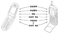
도 1b는 이동 통신 단말기 간의 여러 가지 통화 모드를 설명하기 위한 도면.1B is a view for explaining various call modes between mobile communication terminals.
도 2는 종래의 SIP 메시지를 이용한 화상 통화를 위한 신호 처리 과정을 나타낸 신호 흐름도.2 is a signal flow diagram illustrating a signal processing procedure for a video call using a conventional SIP message.
도 3은 종래의 H.323 프로토콜을 이용한 화상 통화를 위한 신호 처리 과정을 나타낸 신호 흐름도.3 is a signal flow diagram illustrating a signal processing procedure for a video call using a conventional H.323 protocol.
도 4는 종래의 이동 통신 단말기를 이용하여 복수의 통화 모드로 통화하는 과정을 설명하기 위한 순서도.4 is a flowchart illustrating a process of talking in a plurality of call modes using a conventional mobile communication terminal.
도 5는 종래의 이동 통신 단말에서의 통화 모드의 조작 예를 나타낸 도면.5 is a diagram illustrating an example of operation of a call mode in a conventional mobile communication terminal.
도 6a는 본 발명의 바람직한 일 실시예에 따른 통화 모드별 통화로 설정 서비스를 적용할 수 있는 통신 시스템의 일예를 나타낸 도면.6A illustrates an example of a communication system to which a call setting service for each call mode may be applied according to an exemplary embodiment of the present invention.
도 6b는 본 발명의 바람직한 일 실시예에 따른 통화 모드별 통화로 설정 서비스의 적용 예를 나타낸 도면.6B is a diagram illustrating an application example of a call path setting service for each call mode according to an exemplary embodiment of the present invention.
도 6c는 본 발명의 바람직한 일 실시예에 따른 다이얼링 넘버를 설명하기 위 한 도면.6C is a diagram for explaining a dialing number according to one preferred embodiment of the present invention.
도 7a는 본 발명의 바람직한 일 실시예에 따른 통화 모드별 통화로 설정 과정을 나타낸 순서도.7A is a flowchart illustrating a call setup process by call mode according to an exemplary embodiment of the present invention.
도 7b는 본 발명의 바람직한 일 실시예의 변형예에 따른 통화 모드별 통화로 설정 과정을 나타낸 순서도.7B is a flowchart illustrating a call setting process for each call mode according to a modification of the preferred embodiment of the present invention.
도 8은 본 발명의 바람직한 다른 실시예에 따른 통화 모드별 통화로 설정 과정을 나타낸 순서도.8 is a flowchart illustrating a call setup process for each call mode according to another exemplary embodiment of the present invention.
도 9는 본 발명의 바람직한 일 실시예에 따른 통화 모드별 통화로 설정 과정에서 착신 단말의 응답 과정을 나타낸 순서도.9 is a flowchart illustrating a response process of a called terminal in a call path setting for each call mode according to an embodiment of the present invention.
도 10은 본 발명의 바람직한 일 실시예에 따른 발신측 이동 통신 단말기의 구성을 개략적으로 나타낸 도면.10 is a view schematically showing the configuration of a calling mobile terminal according to an embodiment of the present invention.
도 11은 본 발명의 바람직한 일 실시예에 따른 발신측 이동 통신 단말기의 모듈 구성을 나타낸 도면.11 is a diagram showing a module configuration of a calling mobile terminal according to an embodiment of the present invention.
도 12는 본 발명의 바람직한 일 실시예에 따른 통화 모드별 통화로 설정 서비스를 위한 발신 단말의 사용자 인터페이스 조작 예를 나타낸 도면.12 illustrates an example of a user interface operation of a calling terminal for a call path setting service for each call mode according to an exemplary embodiment of the present invention.
* 도면의 주요 부분에 대한 부호의 설명 *Explanation of symbols on the main parts of the drawings
601 : 발신 단말 603 : 발신측 교환기601: originating terminal 603: originating exchange
605 : 착신 단말 607 : 착신측 교환기605: terminating terminal 607: terminating exchange
609 : 통신 네트워크 611 : 서비스 제공 장치609
1000 : 이동 통신 단말기1000: mobile communication terminal
본 발명은 통신 네트워크에서 발신 단말과 착신 단말 간의 호 설정시 다이얼링 번호에 포함된 통화 모드 구분 코드를 이용하여 통화 모드별로 통화로를 구분하여 설정하는 방법 및 장치에 관한 것이다.The present invention relates to a method and apparatus for distinguishing and setting a call path for each call mode by using a call mode identification code included in a dialing number when establishing a call between a calling terminal and a called terminal in a communication network.
일반적으로 기존의 전화기는 사람 간의 음성 통화만을 지원함에 따라 단순히 해당 전화기의 전화번호를 통해 발신 전화기와 착신 전화기 사이에 통화로를 설정하는 데 주로 사용되었다. 한편, 전자, 통신 분야 등의 기술 발전에 힘입어 전화기 간에 통화하는 모드가 늘어남에 따라 현재에는 도 1a에 도시한 통신 네트워크와 같은 통신망에서 발신 전화기와 착신 전화기가 여러 가지 통화 모드로 통화하는 것이 가능하게 되었다. 통화 모드는 예를 들어 음성 통화, 동영상 통화, 정지 영상 통화, 데이터 통화 등을 말한다.In general, the existing phone only supports voice calls between people, so it was mainly used to establish a call path between the calling phone and the called phone through the phone number of the corresponding phone. On the other hand, due to the increase in the mode of communication between telephones due to the development of technology in the field of electronics and communication, it is now possible for the calling telephone and the called telephone to talk in various call modes in a communication network such as the communication network shown in FIG. Was done. The call mode refers to a voice call, a video call, a still video call, a data call, for example.
이처럼 이동 통신 단말기를 포함한 전화기를 이용하면, 발신 전화기와 착신 전화기가 다양한 통화 모드로 통화하는 것이 가능하다. 예를 들면, 도 1b에 도시한 바와 같이, 발신 전화기와 착신 전화기는 음성 통화 모드, 화상 통화 모드, 채팅 통화 모드, 네트워크 게임 통화 모드, 파일 전송 통화 모드, 데이터 세션 통화 모드 등으로 통화할 수 있다. 특히, 휴대폰, PDA 폰 등과 같은 이동 통신 단말기를 이용하면, 장소에 제한됨이 없이 자유롭게 통신 서비스와 인터넷 등을 이용할 수 있다. 앞서 언급한 여러 가지 통화 모드에 대하여 아래에서 예를 들어 설명한다.Using the telephone including the mobile communication terminal as described above, it is possible for the calling telephone and the called telephone to talk in various call modes. For example, as shown in FIG. 1B, the calling phone and the called phone can make a call in a voice call mode, a video call mode, a chat call mode, a network game call mode, a file transfer call mode, a data session call mode, and the like. . In particular, when using a mobile communication terminal such as a mobile phone, PDA phone, etc., a communication service and the Internet can be freely used without being limited to a place. The various call modes mentioned above will be described by way of example below.
먼저, 발신 단말기와 착신 단말기 사이의 하이퍼텍스트 전송 규약(HTTP) 통화 모드를 간략히 설명한다. HTTP 통화 모드는 클라이언트 단말기와 서버 단말기간의 일대일 메시지 교환 구조를 갖는 것을 말한다. 예를 들면, POP3 등의 메일 클라이언트도 HTTP 통화 모드와 같은 메시지 교환 구조를 갖는다. 즉 HTTP 통신 모드의 경우, 클라이언트의 HTTP 브라우저는 사용자의 요구에 따라 서버로 'GET' 요청(request) 메시지를 전송하고, 서버는 그에 따라 '200' OK(요구를 처리하여 데이터를 전송함) 또는 '404' Not found(해당 문서 없음) 등의 응답(Response) 메시지를 회신한다. 한편, HTTP 통신에 있어서, 클라이언트 사용자가 게시판에 글을 올리는 경우 클라이언트는 'PUT'이나 'POST' 요청 메시지를 서버로 전송하고, 서버는 그 내용을 처리했다는 '200' OK 메시지를 클라이언트로 전송한다. 이러한 과정을 통해, 클라이언트 단말기와 서버 단말기는 HTTP 통신 모드로 통화한다. 다음은 좀더 복잡한 프로토콜을 이용한 화상 통화에 대하여 설명한다.First, the hypertext transfer protocol (HTTP) call mode between the calling terminal and the called terminal will be briefly described. The HTTP call mode refers to a one-to-one message exchange structure between a client terminal and a server terminal. For example, a mail client such as POP3 also has a message exchange structure like the HTTP call mode. That is, in the HTTP communication mode, the client's HTTP browser sends a 'GET' request message to the server according to the user's request, and the server accordingly sends a '200' OK (processing the request to send data) or Return a response message such as '404' Not found. On the other hand, in HTTP communication, when a client user posts on a bulletin board, the client sends a 'PUT' or 'POST' request message to the server, and the server sends a '200' OK message indicating that the content has been processed. . Through this process, the client terminal and the server terminal talk in the HTTP communication mode. The following describes a video call using a more complicated protocol.
도 2는 종래의 SIP(Session Initiation Protocol) 메시지를 이용한 화상 통화를 위한 신호 처리 과정을 나타낸 신호 흐름도이다.2 is a signal flow diagram illustrating a signal processing procedure for a video call using a conventional Session Initiation Protocol (SIP) message.
도 2를 참조하면, SIP의 호 설정은 코덱(Codec)이나 단말기 기능 등에 관한 정보를 포함하는 세션(Session)에 대한 정보를 교섭(Negotiation)하기 위하여 일반적인 요청-응답(Request-Response) 구조가 아니라 Request(INVITE), Provisional Response(180 Ringing: 벨소리 울림), Final Response(200 OK) 및 Acknowledgement(ACK)의 3단계 구조를 갖는다. 구체적으로 클라이언트가 서버로 호를 설정하자는 INVITE 메시지를 전송한다(단계 201). 서버는 착신측에서 벨이 울리고 있다는 의미의 180 Ringing 메시지를 클라이언트로 전송한다(단계 203). 또한, 서버는 착신측이 전화를 받았다는 200 OK 메시지를 클라이언트로 전송한다(단계 205). 그 후, 클라이언트가 200 OK 메시지로 수신한 착신측 기능을 확인하였다는 ACK 메시지를 서버로 전송한다(단계 207). 이러한 과정의 수행 결과, 클라이언트와 서버 간에는 호 설정이 이루어지고 클라이언트와 서버가 화상 통화한다(단계 209).Referring to FIG. 2, call establishment of SIP is not a general request-response structure for negotiating information on a session including information on a codec or a terminal function. It has a three-step structure: Request (INVITE), Provisional Response (180 Ringing), Final Response (200 OK), and Acknowledgement (ACK). Specifically, the client sends an INVITE message to set up a call to the server (step 201). The server sends a 180 Ringing message to the client indicating that the called party is ringing (step 203). The server also sends a 200 OK message to the client indicating that the called party has answered the call (step 205). Thereafter, the client sends an ACK message indicating that the called party has received the 200 OK message to the server (step 207). As a result of this process, call setup is established between the client and the server, and the client and server make a video call (step 209).
화상 통화 중에 클라이언트는 화상 이외의 데이터를 전달하기 위한 INFO 메시지를 서버로 전송한다(단계 211). 서버는 INFO 메시지에 대한 응답으로서 INFO 메시지의 수신을 확인하는 200 OK 메시지를 클라이언트로 전송한다(단계 213). 이때, INFO 메시지와 200 OK 메시지는 클라이언트와 서버 사이에서 여러 번 왕복될 수 있다. 그 후, 호를 끊고자 하는 경우, 예를 들어 클라이언트가 서버로 BYE 메시지를 송신한다(단계 215). BYE 메시지를 수신한 서버는 200 OK 메시지를 상대편으로 전송하다(단계 217). 이 과정의 결과, 클라이언트와 서버의 화상 통화 모드는 해제된다.During the video call, the client sends an INFO message to the server for delivering data other than video (step 211). The server sends a 200 OK message to the client confirming receipt of the INFO message in response to the INFO message (step 213). In this case, the INFO message and the 200 OK message may be round-trip several times between the client and the server. Then, if the user wants to hang up, for example, the client sends a BYE message to the server (step 215). The server receiving the BYE message sends a 200 OK message to the other party (step 217). As a result of this process, the video call modes of the client and server are released.
이처럼, 화상 통화를 위해서는 약간 복잡한 프로토콜을 이용해야 한다. 즉, 최종 응답(Final response)이 오기 전까지 정보 응답 또는 사전 응답(informational/provisional response)이라고 하는 처리 과정을 반복하면서 요청에 대한 응답을 처리해야 한다. 이때, 여러 개의 요청과 응답이 하나의 그룹을 이루어 하나의 서비스를 제공할 수도 있다.As such, video calls require the use of slightly more complex protocols. That is, a response to a request must be processed while repeating a process called an information response or an informative / provisional response until a final response comes. In this case, several requests and responses may be provided in one group to provide one service.
도 3은 종래의 H.323 프로토콜을 이용한 화상 통화를 위한 신호 처리 과정을 나타낸 신호 흐름도이다.3 is a signal flow diagram illustrating a signal processing procedure for a video call using a conventional H.323 protocol.
도 3을 참조하면, H.323 프로토콜을 이용한 화상 통화는 발신측 클라이언트와, 단말기의 망 접속을 관장하는 RAS(Registration, Administration and Status) 서버, 및 수신측 서버에 의해 이루어진다. 또한, H.323 프로토콜을 이용한 화상 통화에서는 채널을 할당하는 H.225 프로토콜, 발착신간의 호를 연결하고 끊는 Q.731 프로토콜, 설정될 논리 채널과 단말기 기능을 설정(Set up)하고 논리 채널을 열고 닫는 H.245 프로토콜이 복합적으로 작용하여 호를 연결한다.Referring to FIG. 3, a video call using the H.323 protocol is made by a calling client, a RAS (Registration, Administration and Status) server that manages the network connection of the terminal, and a receiving server. In addition, in a video call using the H.323 protocol, the H.225 protocol for allocating channels, the Q.731 protocol for connecting and disconnecting calls to and from an originator, the logical channel to be set and the terminal functions are set up, and the logical channel is established. The H.245 protocol, which opens and closes in combination, connects the calls.
구체적으로, 클라이언트는 RAS 서버로 채널 연결 허가를 받기 위해서 ARQ(Admission ReQuest) 메시지를 보낸다(단계 301). 접속이 허락된 단말이면, RAS 서버는 클라이언트로 ACF(Admission ConFirm) 메시지를 보낸다(단계 303). 그 다음에, 클라이언트는 착신측 서버와 호를 열기 위한 Setup 메시지를 보낸다(단계 305). 서버는 클라이언트로부터 수신한 Setup 메시지에 대한 응답으로서 수신을 확인하는 Call Proceeding 메시지를 클라이언트로 보낸다(단계 307).Specifically, the client sends an ARQ (Admission ReQuest) message to the RAS server to receive the channel connection permission (step 301). If the terminal is allowed to access, the RAS server sends an ACF (Admission ConFirm) message to the client (step 303). The client then sends a Setup message to open the call with the called server (step 305). The server sends a Call Proceeding message to the client confirming receipt in response to the Setup message received from the client (step 307).
착신측 서버도 발신측 클라이언트의 경우와 유사하게 RAS 서버에 채널 연결 허가 절차를 밟는다. 즉 착신측 서버는 RAS 서버로 채널 연결 허가를 받기 위해서 ARQ 메시지를 전송한다(단계 309). 접속이 허락된 단말이면, RAS 서버는 착신측 서버로 ACF 메시지를 보낸다(단계 311).The destination server goes through a channel connection grant procedure to the RAS server similarly to the originating client. That is, the called server transmits an ARQ message to the RAS server to receive a channel connection permission (step 309). If the terminal is allowed to connect, the RAS server sends an ACF message to the called server (step 311).
그 후, 착신측 서버는 Q.731 프로토콜을 이용하여 발신측 클라이언트에게 벨 을 울렸다는 Alerting 메시지를 전송한다(단계313). 또 착신측 서버는 착신 단말 가입자가 수화기를 들었다는 Connect 메시지를 보낸다(단계 315). 위의 과정의 수행 결과, 클라이언트측 발신 단말기와 서버측 착신 단말기가 화상 통화 모드로 통화한다(단계 317).Thereafter, the called server sends an alerting message indicating that the calling client has ringed using the Q.731 protocol (step 313). The called server sends a Connect message indicating that the called terminal subscriber picked up the receiver (step 315). As a result of the above process, the client-side calling terminal and the server-side called terminal make a call in the video call mode (step 317).
위에서 언급한 단계 317 중에 발신 단말기와 착신 단말기는 H.245 프로토콜을 교환하여 화상 통화한다. 즉 H.245 프로토콜 교환은 단말기 기능을 상대방에게 알리는 TerminalCapabilitySet과 그 응답인 TerminalCapabilitySetAck, 그리고 호 설정 및 호 관리에 있어서 마스터(Master)와 슬래이브(Slave)를 결정하기 위한 MasterSlaveDetermination과 MasterSlaveDeterminationAck, 여러 가지 멀티미디어 데이터를 구분해내기 위해 Multiplex Entry를 교환하는 MultiplexEntrySend와 MultiplexEntrySendAck, 및 논리적 채널을 여는 OpenLogicalChannel과 OpenLogicalChannelAck 메시지를 포함한다. 또한, 상술한 H.245 프로토콜 교환은 Q.731 메시지의 옵션으로 FastStart를 사용한 경우에 생략된다.During the above mentioned
그 다음에, 클라이언트측 발신 단말기와 서버측 착신 단말기는 H.225 프로토콜로 CloseLogicalChannel과 CloseLogicalChannelAck를 주고받아서 채널을 끊는다(단계 319, 단계 321). 또한 발신 단말기는 ReleaseComplete 메시지를 착신 단말기로 전송하여 시그널링 채널을 제거한다(단계 323). 그 후, 발신 단말기와 착신 단말기는 DRQ(Disengage ReQuest) 메시지를 RAS 서버로 각각 전송한다(단계 325, 단계 327). 그리고 발신 단말기와 착신 단말기는 RAS 서버로 호 종료를 알리는 DCF(Disengage ConFirm) 메시지를 전송하고 접속을 종료한다(단계 329, 단계 331).The client-side calling terminal and the server-side called terminal then disconnect the channel by exchanging CloseLogicalChannel and CloseLogicalChannelAck using the H.225 protocol (
위에서 언급한 여러 가지 통화 모드를 이용하기 위한 종래의 방법에 대하여 아래에서 설명한다. 도 4는 종래의 이동 통신 단말기를 이용하여 복수의 통화 모드로 통화하는 과정을 설명하기 위한 순서도이다.The conventional method for using the various call modes mentioned above is described below. 4 is a flowchart illustrating a process of making a call in a plurality of call modes using a conventional mobile communication terminal.
도 4를 참조하면, 먼저 발신 단말기를 사용하는 발신 단말 가입자가 단말기의 디스플레이에 표시된 사용자 인터페이스를 조작하여 음성 통화를 시도한다(단계 401). 이때 발신 단말기는 사용자에 의해 자동적으로 음성 통화 모드 상태가 된다(단계 403). 사용자가 발신 단말기의 통화 버튼을 누르면, 발신 호는 이동 통신망 내의 교환기를 통해 착신 단말기로 전달된다. 이러한 과정을 통해 발신 단말기와 착신 단말기는 음성 통화 모드로 접속된다(단계 405). 이러한 과정의 수행 결과, 발신 단말기와 착신 단말기는 음성 통화 모드로 통화한다.(단계 407). 발신 단말기 또는 착신 단말기에 의해 통화가 종료되면, 음성 통화 모드는 해제된다(단계 409).Referring to FIG. 4, first, a calling terminal subscriber using a calling terminal attempts a voice call by operating a user interface displayed on a display of the terminal (step 401). At this time, the calling terminal automatically enters the voice call mode by the user (step 403). When the user presses the call button of the calling terminal, the calling call is transferred to the called terminal through the exchange in the mobile communication network. Through this process, the calling terminal and the called terminal are connected in the voice call mode (step 405). As a result of this process, the calling terminal and the called terminal make a call in the voice call mode (step 407). When the call is terminated by the calling terminal or the called terminal, the voice call mode is released (step 409).
한편, 발신 단말 가입자가 다시 발신 단말기의 사용자 인터페이스를 조작하여 데이터 통화를 시도한다(단계 411). 이때 발신 단말기는 예를 들어 사용자가 사용자 인터페이스의 메뉴를 여러 단계에 걸쳐 단계적으로 선택함으로써, 패킷 데이터 통화 모드 상태가 된다(단계 413). 사용자가 발신 단말기의 통화 버튼을 누르면, 발신 호는 이동 통신망 내의 교환기에 전달되고, 이동 통신망 내의 교환기와 망 연동 장치 등에 의해 발신 단말기가 핸드폰, 웹 서버 등의 착신 단말기와 접속된다(단계 415).On the other hand, the calling terminal subscriber again attempts to make a data call by manipulating the user interface of the calling terminal (step 411). At this time, the calling terminal enters a packet data call mode state by, for example, the user stepwise selecting a menu of the user interface in several steps (step 413). When the user presses the call button of the originating terminal, the originating call is transferred to the exchange in the mobile communication network, and the originating terminal is connected with the destination terminal such as a mobile phone, a web server, etc. by the exchange and the network interworking device in the mobile communication network (step 415).
그 후, 발신 단말기는 패킷 데이터 통화 모드로 착신 단말기에서 제공하는 화상 통화, 채팅, 네트워크 게임, 파일 송수신 중 적어도 하나의 데이터 서비스를 이용하게 된다(단계 417). 발신 단말기 또는 착신 단말기가 패킷 데이터 통화 모드를 종료하면, 패킷 데이터 통화 모드는 해제된다(단계 419).Thereafter, the calling terminal uses at least one data service of a video call, a chat, a network game, and file transmission and reception provided by the called terminal in the packet data call mode (step 417). When the originating terminal or the terminating terminal ends the packet data call mode, the packet data call mode is released (step 419).
이와 같이, 기존의 개인 휴대 단말기를 이용하여 다양한 통화 모드를 사용하는 경우, 발신 단말 가입자는 음성 통화 모드 이외의 특정 통화 모드에 대하여 사용자 인터페이스를 여러 단계에 걸쳐 조작해야 한다는 불편함이 있었다. 이러한 사용자 인터페이스 조작 과정에 대하여 아래에서 예를 들어 설명한다.As such, when various call modes are used by using a conventional personal portable terminal, the calling terminal subscriber has an inconvenience in that the user interface must be operated in various steps for a specific call mode other than the voice call mode. This user interface manipulation process is described below with an example.
도 5는 종래의 이동 통신 단말기에서의 특정 통화 모드의 조작 예를 보여주는 도면이다.5 is a diagram illustrating an operation example of a specific call mode in a conventional mobile communication terminal.
도 5를 참조하면, 발신 단말 가입자가 네트워크 게임을 하고자 하는 경우, 발신 단말기는 데이터 통신 모드로 해당 서버에 접속하기 위하여 준비되어야 한다. 이를 위해, 발신 단말 가입자는 발신 단말기의 대기 모드 상태에서 특정 키 또는 메뉴를 선택한 후 일련의 사용자 인터페이스를 조작하여야 한다.Referring to FIG. 5, when the calling terminal subscriber wants to play a network game, the calling terminal should be prepared to access the corresponding server in the data communication mode. To this end, the calling terminal subscriber should operate a series of user interfaces after selecting a specific key or menu in the standby mode of the calling terminal.
즉, 발신 단말 가입자는 발신 단말기의 대기 모드 상태에서 특정 키 또는 메뉴를 순차적으로 눌러 데이터 통신 모드의 특정 메뉴를 선택하고, 접속 버튼을 눌러 해당 사이트의 서버에 접속을 시도한다. 그 후, 해당 사이트에 접속되면, 발신 단말 가입자는 해당 사이트의 서버에서 제공하는 메뉴를 선택하고, 선택한 메뉴에 상응하는 네트워크 게임 서비스를 제공받는다.That is, the calling terminal subscriber sequentially selects a specific menu of the data communication mode by pressing specific keys or menus in the standby mode of the calling terminal, and attempts to connect to the server of the corresponding site by pressing the access button. Then, when connected to the site, the calling terminal subscriber selects a menu provided by the server of the site, and is provided with a network game service corresponding to the selected menu.
그러나 종래에 경우, 이동 통신 단말기로 여러 가지 통화 모드를 이용하여 통화하거나 동시에 2개 이상의 통화 모드로 통화하는 것이 가능하였지만, 실질적으로 각 통화 모드를 사용하기 위해서는 이동 통신 단말기의 사용자 인터페이스를 여러 단계에 걸쳐 조작해야 한다는 불편함이 있다. 즉 종래의 이동 통신 단말기에서 다양한 통화 모드를 이용하기 위해서는 이동 통신 단말기를 사용하는 사용자가 음성 통화 이외에 화상 통화, 채팅, 네트워크 게임, 파일 전송 등의 서비스를 선택하기 위하여 사용자 인터페이스를 여러 단계에 걸쳐 조작해야 한다는 단점이 있다.In the related art, however, it was possible to make a call using various call modes or to make a call in two or more call modes at the same time. However, in order to use each call mode, the user interface of the mobile communication terminal may be used in various stages. It is inconvenient to operate over. That is, in order to use various call modes in a conventional mobile communication terminal, a user who uses the mobile communication terminal manipulates the user interface in several steps to select a service such as video call, chat, network game, file transfer, etc. in addition to voice call. The disadvantage is that it must.
또한, 종래의 통신 네트워크에서는 아래의 표 1과 같이 음성 통화를 위한 번호만으로 각각의 통화 모드를 연결하는 데에 있어서 착신자가 동일한 경우 각 통화 모드를 구분할 방법이 없었다. 다시 말해서, 현재의 다이얼링 번호는 정보통신부 세칙에 따라 통신망 번호, 지역 번호, 가입자 국번호, 가입자 개별 번호의 체계를 가진 국내 번호 체계를 사용하고 있다. 따라서 종래의 전화번호로는 이동 통신 단말기에서 여러 가지 통화 모드를 지원하는 데 한계가 있다.In addition, in the conventional communication network, as shown in Table 1 below, there is no method of distinguishing each call mode when the called party is the same in connecting each call mode with only a number for voice call. In other words, the current dialing number uses a domestic numbering system having a network number, area code, subscriber station number, and subscriber individual number system in accordance with the Ministry of Information and Communication. Therefore, the conventional telephone number has a limitation in supporting various call modes in the mobile communication terminal.
또한, 여러 가지 버튼이나 메뉴를 이용하여 각 통화 모드를 구분하는 방법도 고려할 수 있으나, 위에서도 언급한 바와 같이 그것은 사용자가 통화 시도 중 지속적으로 화면을 보면서 버튼을 조작해야하는 사용자 인터페이스의 조작 행동을 요구하기 때문에 통화 조작의 용이성을 떨어뜨린다. 게다가, 단축 다이얼이나 전화번호부 상에서 한 사람 또는 하나의 착신 단말기에 대해 여러 가지로 접근하는 방법에 있어서도 일관성을 유지하기가 용이하지 않다.In addition, it is possible to consider a method of distinguishing each call mode by using various buttons or menus, but as mentioned above, it requires a user interface operation action that requires the user to operate buttons while continuously watching the screen during a call attempt. This reduces the ease of call manipulation. In addition, it is not easy to maintain consistency even in various ways of accessing one person or one called terminal on a speed dial or phone book.
본 발명의 목적은 복수의 접속 망을 포함하고 진화하는 통신 네트워크 내에서 다이얼링 번호를 이용하여 통화 모드 또는 특정 통화 모드의 접속망을 간편하게 설정할 수 있는 통화 모드별 통화로 설정 방법 및 장치을 제공하는 것이다.SUMMARY OF THE INVENTION An object of the present invention is to provide a method and apparatus for setting a call mode by call mode, which includes a plurality of access networks and can easily set a call mode or a specific call mode access network by using a dialing number in an evolving communication network.
본 발명의 다른 목적은 음성 통화, 화상 통화, 채팅, 네트워크 게임, 파일 전송 등의 여러 가지 통화 모드를 다이얼링 번호를 누르는 것만으로 간편하게 설정할 수 있는 통화 모드별 통화로 설정 방법 및 장치를 제공하는 것이다.Another object of the present invention is to provide a method and apparatus for setting a call mode by call mode, which can be set simply by pressing a dialing number for various call modes such as voice call, video call, chat, network game, and file transfer.
본 발명의 또 다른 목적은 발신측 이동 통신 단말에서 다이얼링 번호를 이용하여 특정 통화 모드를 미리 설정함으로써, 발신 단말과 착신 단말 간의 호 설정시 통신 네트워크 내의 불필요한 트래픽을 감소시킬 수 있는 통화 모드별 통화로 설정 방법 및 장치를 제공하는 것이다.
Another object of the present invention is to set a specific call mode using a dialing number in the calling mobile communication terminal in advance, thereby reducing the unnecessary traffic in the communication network when setting up a call between the calling terminal and the called terminal. It is to provide a setting method and apparatus.
본 발명의 상술한 목적을 달성하기 위하여, 본 발명의 일 측면에 따르면, 적어도 하나의 발신 단말을 관리하는 발신측 교환기(MSC) 및 적어도 하나의 착신 단말을 관리하는 착신측 교환기(MSC)를 포함하는 통신 네트워크 내에서 상기 발신측 교환기에서 통화 모드별로 통화로를 설정하는 방법에 있어서, 상기 발신 단말로부터 호 접속 요구 신호를 수신하는 단계-여기서, 상기 호 접속 요구 신호는 상기 발신 단말에 상응하는 발신 단말 식별자, 상기 착신 단말에 상응하는 착신 단말 식별자 및 통화 모드 구분 코드를 포함하고 상기 통화 모드 구분 코드는 확장 구분자 및 통화 모드 번호를 포함함-, 상기 호 접속 요구 신호에 포함된 통화 모드 구분 코드를 분석하여 통화 모드를 결정하는 단계, 상기 결정된 통화 모드에 상응하여 상기 홈 위치 등록기(HLR)로 착신 단말의 위치 정보를 요구하는 단계, 상기 홈 위치 등록기(HLR)로부터 얻은 착신 위치 정보에 따라 상기 착신측 교환기에 ISUP 호 접속 요구 신호를 전송하는 단계, 상기 착신측 교환기로부터 ISUP 호 접속 응답 신호를 수신하는 단계-여기서, 상기 착신측 교환기는 상기 착신 단말을 호출함- 및 상기 착신 단말의 응답에 따라 상기 착신측 교환기와 연동하여 상기 발신 단말과 상기 착신 단말과의 사이에 통화로를 형성하는 단계를 포함하는 통화 모드별 통화로 설정 방법을 제공할 수 있다.In order to achieve the above object of the present invention, according to an aspect of the present invention, includes an originating side exchange (MSC) managing at least one originating terminal and a called side exchange (MSC) managing at least one destination terminal. A method for setting a call path for each call mode in the calling exchange in a communication network, the method comprising: receiving a call connection request signal from the originating terminal, wherein the call connection request signal corresponds to an originating terminal. A terminal identifier, a called terminal identifier corresponding to the called terminal, and a call mode distinguishing code, wherein the call mode distinguishing code includes an extension identifier and a call mode number; and, a call mode distinguishing code included in the call connection request signal. Analyzing and determining a call mode, and attaching to the home location register (HLR) corresponding to the determined call mode. Requesting location information of a new terminal, transmitting an ISUP call connection request signal to the called exchange according to the called location information obtained from the home location register (HLR), and receiving an ISUP call connection response signal from the called exchange. Receiving, wherein the called side exchange calls the called terminal; and forming a call path between the calling terminal and the called terminal in cooperation with the called side exchange according to the response of the called terminal. It may provide a method of setting a call for each call mode comprising a.
삭제delete
본 발명의 다른 측면에 따르면, 적어도 하나의 발신 단말을 관리하는 발신측 교환기(MSC) 및 적어도 하나의 착신 단말을 관리하는 착신측 교환기(MSC)를 포함하는 이동 통신망 내에서 상기 발신 단말에서 통화 모드별로 통화로를 설정하는 방법에 있어서, 상기 발신측 교환기로 호 접속 요구 신호를 전송하는 단계-여기서, 상기 호 접속 요구 신호는 상기 발신 단말에 상응하는 발신 단말 식별자, 상기 착신 단말에 상응하는 착신 단말 식별자, 및 통화 모드 구분 코드를 포함함- 및 상기 발신측 교환기와 상기 착신측 교환기의 연동에 의해 상기 발신 단말과 상기 착신 단말 사이에 통화로가 형성되는 단계를 포함하되, 상기 발신 단말과 상기 착신 단말은 상기 통화로를 이용하여 상기 통화 모드 구분 코드에 상응하는 통화 모드로 통화하고, 상기 통화 모드 구분 코드는 확장 구분자 및 통화 모드 번호를 포함하는 것을 특징으로 하는 통화 모드별 통화로 설정 방법을 제공할 수 있다.According to another aspect of the present invention, a call mode in the calling terminal in a mobile communication network including a calling side exchange (MSC) managing at least one originating terminal and a called side exchange (MSC) managing at least one called terminal. A method for setting a call path for each call, the method comprising: transmitting a call connection request signal to the originating exchange, wherein the call connection request signal is a calling terminal identifier corresponding to the calling terminal and a called terminal corresponding to the called terminal. An identifier, and a call mode identification code; and forming a call path between the calling terminal and the called terminal by interworking the calling exchange and the called exchange, wherein the calling terminal and the called terminal are formed. The terminal makes a call in a call mode corresponding to the call mode classification code by using the call path, and establishes the call mode. The minute code may provide a method for setting a call for each call mode, including an extended separator and a call mode number.
바람직한 실시예에 있어서, 상기 통화 모드는 음성 통화 모드, 회선 데이터 통화 모드 및 패킷 데이터 통화 모드 중 적어도 어느 하나의 통화 모드를 포함하는 것을 특징으로 한다.In a preferred embodiment, the call mode includes at least one of the voice call mode, the line data call mode, and the packet data call mode.
삭제delete
상기 음성 통화 모드, 상기 회선 데이터 통화 모드 및 상기 패킷 데이터 통화 모드는 음성 망, 회선 교환 망 및 패킷 교환 망을 각각 이용하여 설정되는 것을 특징으로 한다.The voice call mode, the circuit data call mode, and the packet data call mode may be set using a voice network, a circuit switched network, and a packet switched network, respectively.
본 발명의 또 다른 측면에 따르면, 적어도 하나의 발신 단말을 관리하는 발신측 교환기(MSC) 및 적어도 하나의 착신 단말을 관리하는 착신측 교환기(MSC)를 포함하는 이동 통신망 내에서 통화 모드별로 통화로를 설정하는 발신측 교환기에 있어서, 상기 발신 단말로부터 호 접속 요구 신호를 수신하는 수단-여기서, 상기 호 접속 요구 신호는 상기 발신 단말에 상응하는 발신 단말 식별자, 상기 착신 단말에 상응하는 착신 단말 식별자 및 통화 모드 구분 코드를 포함하고 상기 통화 모드 구분 코드는 확장 구분자 및 통화 모드 번호를 포함함-, 상기 호 접속 요구 신호에 포함된 통화 모드 구분 코드를 분석하여 통화 모드를 결정하는 수단, 상기 결정된 통화 모드에 상응하여 상기 홈 위치 등록기(HLR)로 착신 단말의 위치 정보를 요구하는 수단, 상기 홈 위치 등록기(HLR)로부터 얻은 착신 위치 정보에 따라 상기 착신측 교환기에 ISUP 호 접속 요구 신호를 전송하는 수단, 상기 착신측 교환기로부터 ISUP 호 접속 응답 신호를 수신하는 수단-여기서, 상기 착신측 교환기는 상기 착신 단말을 호출함- 및 상기 착신 단말의 응답에 따라 상기 착신측 교환기와 연동하여 상기 발신 단말과 상기 착신 단말과의 사이에 통화로를 형성하는 수단을 포함하는 통화 모드별 통화로 설정하는 발신측 교환기를 제공할 수 있다.
바람직한 일 실시예에서, 상기 발신측 교환기는 상기 통화 모드 구분 코드를 인식하는 서비스 교환기(SSP)를 포함하는 무선 지능망(WIN)에 결합된 서비스 제공 서버로부터 상기 통화 모드에 대한 정보를 수신하기 위한 수단을 더 포함하는 것을 특징으로 한다.According to another aspect of the present invention, a call path for each call mode in a mobile communication network including a calling side exchange (MSC) managing at least one originating terminal and a called side exchange (MSC) managing at least one called terminal. In the calling side exchange setting means, means for receiving a call connection request signal from the calling terminal, wherein the call connection request signal is a calling terminal identifier corresponding to the calling terminal, a called terminal identifier corresponding to the called terminal and Means for determining a call mode by analyzing a call mode distinguishing code included in the call connection request signal, the call mode distinguishing code comprising a call mode distinguishing code, the call mode distinguishing code including an extended separator and a call mode number; Means for requesting location information of the called terminal to the home location register (HLR) corresponding to the Means for sending an ISUP call connection request signal to the called side exchange according to called location information obtained from an HLR, and means for receiving an ISUP call connection response signal from the called side exchange, wherein the called side exchange is the called party. A calling party switch configured to make a call per call mode, comprising means for calling a terminal and forming a call path between the calling terminal and the called terminal in association with the called side exchange according to a response of the called terminal. Can be provided.
In a preferred embodiment, the source side exchange means for receiving information on the call mode from a service providing server coupled to a wireless intelligent network (WIN) comprising a service switch (SSP) recognizing the call mode discrimination code. It characterized in that it further comprises.
삭제delete
본 발명의 또 다른 측면에 따르면, 적어도 하나의 발신 단말을 관리하는 발신측 교환기(MSC) 및 적어도 하나의 착신 단말을 관리하는 착신측 교환기(MSC)를 포함하는 이동 통신망 내에서 통화 모드별로 통화로를 설정하는 발신측 이동 통신 단말기에 있어서, 안테나, 상기 안테나에 결합되고, 송신 및 수신 주파수를 분리하는 듀플렉서를 포함하는 고주파 처리부, 상기 고주파 처리부에 결합되고, 베이스 밴드 프로세서 및 주변 장치를 포함하는 기저대역 처리부, 통화 모드 구분 코드를 포함한 다이얼링 번호를 입력받는 사용자 인터페이스 및 저장 수단을 포함하는 상기 주변 장치 및 상기 베이스 밴드 프로세서 및 상기 주변 장치에 결합되고, 상기 다이얼링 번호를 이용하여 통화 모드를 구분 처리하는 통화 모드 처리부를 포함하는 이동 통신 단말기를 제공할 수 있다.According to another aspect of the present invention, a call path for each call mode in a mobile communication network including a calling side exchange (MSC) managing at least one originating terminal and a called side exchange (MSC) managing at least one called terminal. A source-side mobile telecommunication terminal for establishing an antenna, comprising: an antenna, a high frequency processor coupled to the antenna and a duplexer separating a transmission and a reception frequency, a base band coupled to the high frequency processor and including a baseband processor and a peripheral device. A band processor, a user interface for receiving a dialing number including a call mode identification code, and a peripheral device including a storage means, coupled to the base band processor and the peripheral device, and classifying a call mode using the dialing number A mobile communication terminal including a call mode processing unit; Can.
이어서, 첨부한 도면들을 참조하여 본 발명의 바람직한 실시예를 상세히 설명하기로 한다.Next, preferred embodiments of the present invention will be described in detail with reference to the accompanying drawings.
도 6a는 본 발명의 바람직한 일 실시예에 따른 통화 모드별 통화로 설정 서비스를 적용할 수 있는 통신 시스템의 일예를 나타낸 도면이다.6A is a diagram illustrating an example of a communication system to which a call setting service for each call mode may be applied according to an exemplary embodiment of the present invention.
도 6a를 참조하여 본 발명의 바람직한 일 실시예에 따른 통화 모드별 통화로 설정 방법을 개략적으로 설명하면 다음과 같다. 먼저, 발신자가 발신 단말(601)을 이용하여 착신 단말(605)측으로 통화 모드 구분 코드를 포함한 전화번호(이하 '다이얼링 넘버(Dialing Number)'라 한다)를 전송하면, 발신측 교환기(603)는 착신 단말(605)의 위치를 파악한 후, 착신측 교환기(607)로 이동 통신망(609)을 통하여 호 접속 요구 신호를 전송한다. 통화 모드 구분 코드는 확장 구분자와 통화 모드 번호를 포함한다. 그 후, 발신측 교환기(603)는 다이얼링 넘버에 포함된 통화 모드 구분 코드를 인식하고 통화 모드 구분 코드에 상응하는 통화 모드 또는 접속/교환 망을 이용하여 착신측 교환기(607)로 호 접속을 요구한다. 한편, 발신측 교환기는 발신자가 가입되어 있는 통화 모드별 통화로 설정 서비스의 설정 정보를 이용하여, 지능 주변 장치(Intelligent Peripheral; IP)인 서비스 제공 서버(611)로부터 통화 모드 구분 코드에 대한 인식 정보를 수신할 수 있다. 상기의 과정을 통하여, 발신자 및 착신자는 발신자가 선택한 통화 모드를 이용하여 통화를 할 수 있다.Referring to FIG. 6A, a method for setting a call for each call mode according to an exemplary embodiment of the present invention will be described below. First, when the caller transmits a phone number (hereinafter referred to as a 'dialing number') including a call mode classification code to the called
도 6b는 본 발명의 바람직한 일 실시예에 따른 통화 모드별 통화로 설정 서비스의 예를 나타낸 도면이다.6B illustrates an example of a call path setting service for each call mode according to an exemplary embodiment of the present invention.
도 6b를 참조하면, 본 발명의 일 실시예에 따른 통화 모드별 통화로 설정 서비스는 이동 통신 단말(발신 단말)에서 통화 모드 구분 코드를 포함한 다이얼링 넘 버가 발신되면, 통신망 내의 교환기가 통화 모드 구분 코드를 판단하고 특정 통화 모드를 이용하여 발신 단말과 착신 단말 사이에 호 설정을 수행하도록 이루어진다.Referring to FIG. 6B, when a dialing number including a call mode distinguishing code is transmitted from a mobile communication terminal (calling terminal), a call path setting service according to an embodiment of the present invention distinguishes a call mode by the exchange in the communication network. The code is determined and a call setup is performed between the calling terminal and the called terminal using a specific call mode.
한편, 다이얼링 넘버에 포함된 통화 모드 구분 코드를 판단하는 것은 교환기 이외에 교환기에 결합된 별도의 통화 모드 판단 수단에 의해 이루어질 수 있다. 이러한 경우, 교환기는 통화 모드 구분 코드를 지능망 서비스 호로 인식하는 지능 주변 장치(IP)를 통해 인식 정보를 수신하고, 그에 따라 호 설정을 수행할 수 있다. 지능 주변 장치는 본 발명에 따른 통화 모드별 통화로 설정 서비스를 위한 서비스 제공 장치를 포함한다.On the other hand, determining the call mode identification code included in the dialing number may be made by separate call mode determination means coupled to the exchange in addition to the exchange. In this case, the exchange may receive the recognition information through the intelligent peripheral device (IP) that recognizes the call mode classification code as the intelligent network service call, and may perform call setup accordingly. The intelligent peripheral device includes a service providing device for a call setting service for each call mode according to the present invention.
다시 도 6b를 참조하면, 본 발명의 일 실시예에 따른 통화 모드별 통화로 설정 서비스는 이동 통신 단말(발신 단말)이 통화 모드 구분 코드를 포함한 다이얼링 넘버를 발신할 때, 이동 통신 단말이 다이얼링 넘버에 포함된 통화 모드 구분 코드를 판단한 후, 발신측 교환기로 발신 단말에 상응하는 발신 단말 식별자와 착신 단말에 상응하는 착신 단말 식별자를 포함한 호 접속 요구 신호를 전송하도록 이루어진다. 따라서 통신망 내의 교환기는 기존의 방식대로 호 접속 요구 신호에 포함된 발신 단말 및 착신 단말의 식별 정보에 따라 발신 단말과 착신 단말 사이에 호 설정을 수행한다.Referring back to FIG. 6B, a call mode setting service according to an embodiment of the present invention provides a dialing number when a mobile communication terminal (calling terminal) sends a dialing number including a call mode identification code. After determining the call mode discrimination code included in the call mode, the call connection request signal including the calling terminal identifier corresponding to the calling terminal and the called terminal identifier corresponding to the called terminal is transmitted to the calling exchange. Therefore, the exchange in the communication network performs call setup between the calling terminal and the called terminal according to the identification information of the calling terminal and the called terminal included in the call connection request signal in a conventional manner.
또 다시 도 6b를 참조하면, 본 발명의 일 실시예에 따른 통화 모드별 통화로 설정 서비스는 이동 통신 단말(발신 단말)이 통화 모드 구분 코드를 포함한 다이얼링 넘버를 발신할 때, 이동 통신 단말이 다이얼링 넘버에 포함된 통화 모드 구분 코드를 판단한 후, 특정 접속 망에 결합된 발신측 교환기로 통화 모드 구분 코드를 제외한 호 접속 요구 신호를 전송하도록 이루어진다. 따라서 상기 발신측 교환기는 이동 통신 단말에 의해 선택된 접속 망을 통해 기존의 방식대로 발신 단말과 착신 단말 사이에 호 설정을 수행한다. 접속 망은 패킷 데이터망, 회선 데이터망, 음성망을 포함한다.Referring again to FIG. 6B, a call mode setting service for each call mode according to an embodiment of the present invention may be performed when the mobile communication terminal (calling terminal) sends a dialing number including a call mode identification code. After determining the call mode discrimination code included in the number, the call access request signal excluding the call mode discrimination code is transmitted to the source exchange coupled to the specific access network. Therefore, the originating exchange performs call establishment between the originating terminal and the called terminal through the access network selected by the mobile communication terminal in a conventional manner. Access networks include packet data networks, circuit data networks, and voice networks.
이와 같이 본 발명에 따르면, 다이얼링 번호만으로 특정 통화 모드를 선택하여 통화할 수 있다. 즉 발신 단말은 특정 통화 모드를 조작하기 위하여 사용자 인터페이스를 번거롭게 여러 단계에 걸쳐 조작할 필요가 없다. 또한, 발신 단말과 착신 단말은 통신망 또는 발신 단말에서부터 선택된 특정 통화 모드로 음성, 데이터 또는 음성 및 데이터를 송수신하여 통화할 수 있다. 상기 다이얼링 번호에 대하여 아래에서 구체적으로 설명한다.As described above, according to the present invention, only a dialing number can be used to select and make a specific call mode. In other words, the originating terminal does not need to operate the user interface in several steps in order to operate a specific call mode. In addition, the calling terminal and the called terminal may transmit and receive voice, data, or voice and data in a selected call mode from the communication network or the calling terminal. The dialing number will be described in detail below.
도 6c는 본 발명의 바람직한 일 실시예에 따른 다이얼링 번호를 설명하기 위한 도면이다.6C is a diagram for explaining a dialing number according to an exemplary embodiment of the present invention.
도 6c를 참조하면, 본 발명에 따른 다이얼링 번호는 통신망 번호, 지역 번호, 가입자 국번호, 가입자 개별 번호, 확장 구분자 및 통화 모드 번호로 이루어진 전화번호를 포함한다. 여기서, 통신망 번호와 지역 번호는 생략될 수 있다. 또한, 국번호 및 가입자 개별번호는 사용 지역 또는 국가에 따라 적절하게 변경될 수 있다. 게다가, 확장 구분자 및 통화 모드 번호는 두 자리수 이하로 이루어지는 것이 바람직하지만, 특정 자리수로 제한되지 않고 세 자리수 이상의 임의의 자리수로 설정될 수도 있다.
또한, 다이얼링 번호에 포함되는 확장 구분자 및 통화 모드 번호로 이루어진 통화 모드 구분 코드는 아래의 표 2에서 알 수 있는 바와 같이 하나의 단위로써 다이얼링 번호에 포함된다. 여기서, 확장 구분자는 기존의 일반적인 전화 번호인 단말 식별자와 통화 모드 번호를 구분해주는 역활을 담당한다. 즉 상기의 구분 코드가 단말 식별자 이후에 입력된다면, 상기 구분 코드 이후에 입력되는 번호는 통화 모드 번호로 인식하는 것이다. 따라서 상기 통화 모드 구분 코드는 확장 구분자 와 통화 모드 번호를 모두 포함할 경우에 정상적으로 의도된 바를 수행할 수 있을 것이다.
앞서 언급한 다이얼링 번호에 대한 일예를 아래의 표 2에 나타내었다.Referring to FIG. 6C, a dialing number according to the present invention includes a telephone number consisting of a network number, an area code, a subscriber station number, a subscriber individual number, an extended separator, and a call mode number. Here, the network number and area code may be omitted. In addition, the station code and subscriber ID number may be changed according to the region or country of use. In addition, the extension separator and the call mode number are preferably made of two digits or less, but are not limited to a specific digit but may be set to any digit of three or more digits.
In addition, a call mode classification code consisting of an extension separator and a call mode number included in the dialing number is included in the dialing number as one unit as shown in Table 2 below. Here, the extended separator is responsible for distinguishing a terminal identifier, which is an existing general telephone number, and a call mode number. That is, if the identification code is input after the terminal identifier, the number input after the identification code is recognized as a call mode number. Therefore, the call mode classification code may perform what is normally intended when it includes both the extension separator and the call mode number.
An example of the aforementioned dialing number is shown in Table 2 below.
표 2에 나타낸 바와 같이, 본 발명에 따르면, 단말기에서 여러 가지 통화 모드를 구분하기 위하여 확장 구분자 및 통화 모드 번호를 포함한 다이얼링 번호를 이용함으로써, 사용자는 이용하고자 원하는 통화 모드를 매우 간편하게 선택하여 사용할 수 있다. 특히 사용자는 다이얼링 번호를 단축키로 지정함으로써 여러 가지 통화 모드를 더욱 간편하게 이용할 수 있다. 예를 들면, 사용자는 10번 다이얼 단축키에 최근 인기 있는 네트워크 게임 서버에 데이터 통신 모드로 접속하기 위한 다이얼링 번호를 지정 저장하고, 20번 다이얼 단축키에 채팅 서비스 제공 장치에 화상 통화 모드로 접속하기 위한 다이얼링 번호를 지정 저장함으로써 사용자 인터페이스를 여러 단계에 걸쳐 반복적으로 조작할 필요가 없이 매우 간편하게 특정 통화 모드로 접속하여 통화할 수 있다.As shown in Table 2, according to the present invention, by using a dialing number including an extended delimiter and a call mode number to distinguish various call modes in a terminal, a user can select and use a desired call mode very simply. have. In particular, users can use various call modes more easily by assigning dialing numbers as shortcuts. For example, a user may designate and store a dialing number for accessing a recently popular network game server in a data communication mode in dial 10, and dialing for accessing a video service mode to a chat service providing device in dial 20. By assigning and storing numbers, users can easily access and talk in a particular call mode without having to repeatedly manipulate the user interface in several steps.
또한, 이동 통신 단말이 다이얼링 번호를 인식하는 기능을 지원하면, 이동 통신 단말의 사용자는 이동 통신망 내의 교환기에 상관없이 다이얼링 번호를 편리하게 임의로 설정하여 사용할 수 있다. 이러한 경우, 사용자는 적어도 착신 단말에 대한 전호번호와 통화 모드 구분 코드를 포함한 다이얼링 번호를 이동 통신 단말의 메모리에 저장한 후, 필요에 따라 매우 편리하게 통화 모드별 통화로 설정 서비스 를 이용할 수 있다(표 2 참조).In addition, if the mobile communication terminal supports the function of recognizing the dialing number, the user of the mobile communication terminal can conveniently set and use the dialing number irrespective of the switch in the mobile communication network. In this case, the user can store the dialing number including at least the telephone number and the call mode identification code for the called terminal in the memory of the mobile communication terminal, and then use the call setting service for each call mode very conveniently if necessary ( See Table 2).
도 7a는 본 발명의 바람직한 일 실시예에 따른 통화 모드별 통화로 설정 방법을 나타낸 순서도이다. 또한, 도 7b는 본 발명의 바람직한 일 실시예의 변형예에 따른 통화 모드별 통화로 설정 방법을 나타낸 순서도이다.7A is a flowchart illustrating a method for setting a call for each call mode according to an exemplary embodiment of the present invention. 7B is a flowchart illustrating a method for setting a call for each call mode according to a modification of the preferred embodiment of the present invention.
도 7a를 참조하면, 발신측 교환기가 먼저 발신 단말로부터 호 접속 요구 신호를 수신한다(단계 701). 이때, 호 접속 요구 신호는 발신 단말 가입자가 발신 단말에서 다이얼링 번호를 입력하고 통화 버튼을 누름으로써 생성된다. 본 발명에 따른 호 접속 요구 신호는 발신 단말에 상응하는 발신 단말 식별자와 착신 단말에 상응하는 착신 단말 식별자 및 통화 모드 구분 코드를 포함한다. 통화 모드 구분 코드는 확장 구분자와 통화 모드 번호를 포함한다. 여기서, 확장 구분자는 전화기에 있어서 별표(*) 버튼 및 우물정자(#) 버튼 중 두 번의 버튼 입력에 의해 생성된 신호를 의미한다. 또한, 통화 모드 번호는 전화기에 있어서 0번 버튼 및 1번 내지 9번 버튼 중 두 번의 버튼 입력에 의해 생성된 신호를 의미한다. 물론, 본 발명은 확장 구분자 및 통화 모드 번호가 각각 두 번의 버튼 입력에 의해 생성된 신호로 한정되는 것은 아니다. 이것은 사용자 편의를 고려하여 제시한 것이므로, 적절하게 변경가능하다.Referring to FIG. 7A, the originating exchange first receives a call connection request signal from the originating terminal (step 701). At this time, the call connection request signal is generated by the calling terminal subscriber entering the dialing number at the calling terminal and pressing the call button. The call connection request signal according to the present invention includes a calling terminal identifier corresponding to the calling terminal, a called terminal identifier corresponding to the called terminal, and a call mode identification code. The call mode identification code includes an extension separator and a call mode number. Here, the extended separator means a signal generated by two button inputs of an asterisk (*) button and a pound sperm (#) button in the telephone. In addition, the call mode number refers to a signal generated by two button inputs among buttons 0 and 1-9. Of course, the present invention is not limited to the extension delimiter and the call mode number each generated by two button inputs. Since this is presented in consideration of user convenience, it can be changed as appropriate.
이때, 발신 단말로부터 호 접속 요구 신호를 수신한 발신측 교환기는 호 접속 요구 신호에서 통화 모드 구분 코드를 검출한다(단계 703). 물론 이때 발신측 교환기는 확장 구분자 뒤에 결합된 통화 모드 번호를 검출하지 못하면, 기존의 호 설정 절차에 따라 호 설정을 수행한다. 그 후, 발신측 교환기는 통화 모드 구분 코드를 해석한다(단계 705).At this time, the originating exchange that receives the call connection request signal from the originating terminal detects the call mode classification code in the call connection request signal (step 703). Of course, at this time, if the calling exchange does not detect the call mode number coupled after the extension separator, it performs call setup according to the existing call setup procedure. The calling exchange then interprets the call mode identification code (step 705).
통화 모드 구분 코드를 해석한 발신측 교환기는 통화 모드 구분 코드에 상응하는 통화 모드 또는 접속 망을 선택한다(단계 711). 이때, 발신측 교환기는 발신 단말 가입자에 의해 선택된 통화 모드에 대하여 여러 차례에 걸친 복잡한 확인 절차를 수행할 필요가 없다. 즉 발신측 교환기는 사용자의 통화 모드 구분 코드에 따라 바로 호 설정 과정에 착수할 수 있다. 따라서 본 발명에 따르면 발신 단말과 착신 단말간의 호 설정에 있어서, 특정 통화 모드를 지원하는 프로토콜을 이용하여 통화로 설정할 때, 교환기내 또는 교환기 간의 내부 신호 교환에 따른 트래픽을 감소시킬 수 있다.The calling exchange that interprets the call mode classification code selects a call mode or access network corresponding to the call mode classification code (step 711). In this case, the calling exchange does not need to perform a complicated check procedure several times for the call mode selected by the calling terminal subscriber. That is, the originating exchange can immediately start the call setup process according to the call mode classification code of the user. Therefore, according to the present invention, when setting up a call using a protocol supporting a specific call mode in setting up a call between an originating terminal and a called terminal, it is possible to reduce traffic due to internal signal exchange between the exchange or between the exchanges.
그 후, 발신측 교환기는 착신측 교환기와 연동하여 발신 단말과 착신 단말과의 사이에 호를 설정한다(단계 713). 예를 들면, 발신측 교환기는 홈 위치 등록기(HLR)로부터 얻은 착신 위치 정보에 따라 착신측 교환기에 ISUP 호 접속 요구 신호를 전송한다. 그리고 발신측 교환기는 착신측 교환기로부터 ISUP 호 접속 응답 신호를 수신한다. 이때, 착신측 교환기는 착신 단말을 호출한다. 그리고 착신 단말이 응답하면, 발신 단말과 착신 단말 사이에 호(통화로)가 형성된다.Thereafter, the calling exchange establishes a call between the calling terminal and the called terminal in association with the called exchange (step 713). For example, the calling side exchange sends an ISUP call connection request signal to the called side exchange according to the called position information obtained from the home location register (HLR). The originating exchange receives the ISUP call connection response signal from the called exchange. At this time, the called side exchange calls the called terminal. When the called terminal responds, a call (call path) is formed between the calling terminal and the called terminal.
위 과정의 수행 결과, 발신 단말과 착신 단말은 발신 단말 가입자에 의해 선택된 통화 모드로 설정된 통화로를 이용하여 통화한다. 따라서 본 발명에 따른 통화 모드별 통화로 설정 서비스는 사용자에게 여러 가지 통화 모드 사용에 대한 편리성을 제공한다.As a result of the above process, the calling terminal and the called terminal make a call using the call path set to the call mode selected by the calling terminal subscriber. Therefore, the call mode setting service for each call mode according to the present invention provides a user with convenience of using various call modes.
한편, 도 7b를 참조하면, 본 발명에 따른 통화 모드별 통화로 설정 방법은 발신측 교환기가 통화 모드 구분 코드를 인식하거나 판단하지 않고, 발신측 교환기에 결합된 서비스 제공 장치로부터 통화 모드 구분 코드에 대한 인식 정보를 수신하는 과정을 포함할 수 있다(단계 707 및 단계 709). 이러한 본 발명에 따르면, 서비스 제공 장치에서 통화 모드 구분 코드에 대한 인식 정보를 발신측 교환기에 전달하므로, 발신측 교환기에서는 통화 모드별 통화로 설정 서비스를 위한 통화 모드 구분 코드 인식을 위하여 교환기를 소프트웨어적으로 업그레이드 하거나 교환기에 별도의 하드웨어를 장착할 필요가 없다. 한편, 본 명세서에서는 서비스 제공 장치가 서비스 제어점(SCP)과 결합된 서비스 교환기(SSP)와 연동하는 것으로 주로 언급하였지만, 본 발명은 물론 SCP를 통해 SSP가 통화 모드 구분 코드를 인식하고 그 정보를 발신측 교환기에 전달하도록 이루어질 수도 있다.On the other hand, referring to Figure 7b, according to the present invention, the method for setting the call mode for each call mode according to the present invention does not recognize or determine the call mode distinguishing code, but the call mode distinguishing code is connected to the call mode distinguishing code from the service providing apparatus coupled to the calling exchange. And receiving recognition information about the application (
도 8은 본 발명의 바람직한 다른 실시예에 따른 통화 모드별 통화로 설정 과정을 나타낸 순서도이다. 또한, 도 9는 본 발명의 바람직한 일 실시예에 따른 통화 모드별 통화로 설정 과정에서 착신 단말의 응답 과정을 나타낸 순서도이다. 본 실시예에서 이동 통신 단말은 통화 모드별 통화로 설정 서비스를 위한 통화 모드 처리 기능을 포함한다.8 is a flowchart illustrating a call setup process by call mode according to another exemplary embodiment of the present invention. 9 is a flowchart illustrating a response process of a called terminal in a call path setting for each call mode according to an exemplary embodiment of the present invention. In this embodiment, the mobile communication terminal includes a call mode processing function for a call setting service for each call mode.
도 8을 참조하면, 먼저 발신측 이동 통신 단말(발신 단말)에서 발신 단말 가입자에 의해 다이얼링 번호가 입력(단계 800)되면, 발신 단말은 통화 모드 처리부에 의해 다이얼링 번호를 인식한다(단계 801). 그 후, 발신 단말은 다이얼링 번호 내에 특정 통화 모드 구분 코드가 존재하는 지를 판단한다(단계 803). 판단 결과, 특정 통화 모드 구분 코드가 존재하면, 발신 단말은 통화 모드 구분 코드를 인식/해석한다(단계 805). 이때, 발신 단말은 통화 모드 구분 코드에 상응하여 설정된 접속 망 및/또는 통화 모드를 메모리 등의 저장 장치에서 읽어낸다. 즉 발신 단말은 착신 단말과의 접속에 사용할 접속 망을 선택한다(단계 807). 또한 발신 단말은 착신 단말과의 접속에 사용할 통화 모드를 선택한다(단계 809). 위의 단계 807 및 단계 809에 있어서 발신 단말 가입자는 발신 단말을 통해 접속 망만을 선택하거나 또는 통화 모드만을 선택할 수 있다. 그 후, 발신 단말은 통화 모드 구분 코드를 제외한 호 접속 요구 신호를 발신측 교환기로 전송한다(단계 811). 발신측 교환기는 기존의 호 설정 절차에 따라 발신 단말과 착신 단말 사이에 호 설정 작업을 수행한다. 위 과정의 수행 결과, 발신 단말과 착신 단말은 발신 단말 가입자에 의해 선택된 통화 모드로 설정된 통화로를 이용하여 통화한다(단계 813).Referring to FIG. 8, when a dialing number is input (step 800) by a calling terminal subscriber at a calling mobile terminal (sending terminal), the calling terminal recognizes the dialing number by the call mode processor (step 801). Thereafter, the calling terminal determines whether a specific call mode identification code exists in the dialing number (step 803). As a result of the determination, if a specific call mode classification code exists, the calling terminal recognizes / interprets the call mode classification code (step 805). At this time, the calling terminal reads the access network and / or call mode set corresponding to the call mode classification code from a storage device such as a memory. That is, the calling terminal selects an access network to use for connecting with the called terminal (step 807). In addition, the calling terminal selects a call mode to be used for connection with the called terminal (step 809). In
한편 도 9를 참조하면, 착신 단말이 착신측 교환기로부터 호출 신호를 수신(단계 901)하면, 착신 단말은 상기 호출 신호에 응답한다(단계 903). 이때, 착신 단말은 특정 통화 모드를 이용한 통화(단계 905)인 경우, 먼저 자체적으로 상기 특정 통화 모드를 지원하는 지를 판단한다(단계 907). 그 판단 결과, 착신 단말이 특정 통화 모드를 지원하면, 착신 단말은 발신 단말 가입자에 의해 선택된 특정 통화 모드로 발신 단말과 통화한다(단계 909). 만약, 착신 단말이 특정 통화 모드를 지원하지 않으면, 착신 단말은 통화 가능한 통화 모드 또는 기본 통화 모드를 이용하여 발신 단말과 통화한다(단계 911). 예를 들어, 화상 통화인 경우, 착신 단말이 화상 통화 모드를 지원하지 않으면, 착신 단말은 음성 통화 모드를 설정한 후, 발신 단말과 음성 통화 모드를 이용하여 음성 통화만을 수행한다.Meanwhile, referring to FIG. 9, when the called terminal receives the call signal from the called side exchange (step 901), the called terminal responds to the call signal (step 903). In this case, in the case of a call using a specific call mode (step 905), the called terminal first determines whether to support the specific call mode by itself (step 907). As a result of the determination, if the called terminal supports the specific call mode, the called terminal calls the calling terminal in the specific call mode selected by the calling terminal subscriber (step 909). If the called terminal does not support a specific call mode, the called terminal calls the calling terminal using the available call mode or the basic call mode (step 911). For example, in the case of a video call, if the called terminal does not support the video call mode, the called terminal sets the voice call mode and then performs only the voice call using the call terminal and the voice call mode.
도 10은 본 발명의 바람직한 일 실시예에 따른 발신측 이동 통신 단말기의 구성을 개략적으로 나타낸 도면이다. 본 실시예에서는 중간 주파수 방식의 CDMA 단말기를 예를 들어 설명한다.10 is a diagram schematically showing the configuration of a calling mobile terminal according to an embodiment of the present invention. In the present embodiment, an intermediate frequency CDMA terminal is described as an example.
도 10을 참조하면, 본 발명에 따른 이동 통신 단말(1000)은 안테나(1001), 고주파 처리부(1003) 및 기저대역 처리부(1015)를 포함한다. 고주파 처리부(1003)는 안테나에 결합되고, 송신 및 수신 주파수를 분리하는 듀플렉서(1005), 수신부(Rx; 1007), 송신부(Tx; 1009), 중간 주파수부(IF; 1011, 1013)를 포함한다. 중간 주파수는 1.7~1.8㎓ 대역을 두 단계에 걸쳐서 낮출 때 사용된다. 즉 중간 주파수는 제1 중간 주파수 대역으로서 100㎒ 부근과 제2 중간 주파수 대역으로서 5㎒ 부근을 포함한다.Referring to FIG. 10, the
기저대역 처리부(1015)는 모뎀칩(Mobile Station Modem; 1017)을 포함한다. 모뎀칩(1017)은 베이스 밴드 프로세서를 내장하고 있는 단말기의 핵심 부품을 말한다. 모뎀칩(1017)은 고주파 처리부(1003)의 중간 주파수부(1011, 1013)에 결합되고 디지털 신호 처리와 호 처리(Call processing)를 담당한다.The
또한, 기저대역 처리부(1015)는 주변 장치(1019)를 포함한다. 주변 장치(1019)는 메모리 등의 저장 수단 및 사용자 인터페이스를 구비한 입출력 장치를 포함한다. 사용자 인터페이스는 적어도 통화 모드 구분 코드를 포함한 다이얼링 번호를 입력받는 인터페이스를 포함한다.The
또한, 기저대역 처리부(1015)는 통화 모드 처리부(1021)를 포함한다. 통화 모드 처리부(1021)는 모뎀칩(1017) 및 주변 장치(1019)에 결합되고, 상기 다이얼링 번호에 포함된 통화 모드 구분 코드에 따라 통화 모드를 처리한다. 통화 모드는 음성 통화, 화상 통화, 채팅, 네트워크 게임, 파일 전송 등을 위한 음성 통화 모드, 회선 데이터 통화 모드 및 패킷 데이터 통화 모드를 포함한다.The
도 11은 본 발명의 바람직한 일 실시예에 따른 발신측 이동 통신 단말기의 모듈 구성을 나타낸 도면이다.11 is a diagram illustrating a module configuration of a calling mobile terminal according to an embodiment of the present invention.
도 11을 참조하면, 본 발명에 따른 이동 통신 단말은 다양한 운영체계(OS: Operating System)를 시스템의 OS로서 사용할 수 있다. 이러한 OS는 응용 프로그램 인터페이스(API: Application Program Interface; 1100)에 상위 레벨 명령어를 제공하여 각 응용 모듈(1120)의 동작을 제어한다.Referring to FIG. 11, a mobile communication terminal according to the present invention may use various operating systems (OSs) as OSs of a system. The OS provides a high level command to an application program interface (API) 1100 to control the operation of each
이동 통신 단말은 API(1100)로부터 제공되는 상위 레벨 명령어에 따라 각 응용 모듈을 식별하고, 상위 레벨 명령어를 디코딩하여 해당 응용 모듈로 제공하는 상위 레벨 명령어 처리부(1103)를 포함한다. 응용 모듈 제어부(1110)는 상위 레벨 명령어 처리부(1103)로부터 제공된 명령어에 따라 응용 모듈(1120)의 동작을 제어한다. 즉, 상위 레벨 명령어 처리부(1103)는 API(1100)를 통하여 제공된 상위 레벨 명령어에 따라 해당 응용 모듈(1120)이 존재하는지를 식별하고, 해당 응용 모듈(1120)이 존재하는 경우에 해당 응용 모듈(1120)에서 인식할 수 있는 명령어로 디코딩하여 해당 매핑부에 전송하거나 메시지 전송을 제어한다. 여기서, 응용 모듈(1120)은 다이얼링 번호 처리 모듈(1122), 통화 모드 구분 코드 처리 모듈(1124), 통화 모드 처리 모듈(1126) 및 접속 모드 처리 모듈(1128)을 포함한다. 응용 모듈 제어부(1110)는 각 응용 모듈에 대한 매핑부(1112, 1114, 1116, 1118)와 인터페이스부(1113, 1115, 1117, 1119)를 각각 포함한다.The mobile communication terminal includes a high
다이얼링 번호 처리 모듈 매핑부(1112)는 상위 레벨 명령어 처리부(1103)로부터 다이얼링 번호의 입력 신호를 처리하기 위한 상위 레벨 명령어를 제공받아 다이얼링 번호 처리 모듈(1122)에서 처리할 수 있는 디바이스 레벨 명령어로 매핑시키고, 그것을 다이얼링 번호 처리 모듈 인터페이스부(1113)를 통하여 다이얼링 번호 처리 모듈(1122)로 제공한다.The dialing number processing
통화 모드 구분 코드 처리 모듈 매핑부(1114)는 이동 통신 단말에서 지원하는 통화 모드를 바탕으로 사용자에 의해 설정된 통화 모드 설정 정보를 메모리 내의 데이터베이스에서 검색하여 이동 통신 단말의 사용자가 해당 서비스를 요구하는 지를 판단하고 처리하기 위한 부분이다. 즉 통화 모드 구분 코드 처리 모듈 매핑부(1114)는 상위 레벨 명령어 처리부(1103)로부터 통화 모드 구분 코드를 처리하기 위한 상위 레벨 명령어를 제공받아 통화 모드 구분 코드 처리 모듈(1124)이 인식할 수 있는 디바이스 레벨 명령어로 매핑시키고, 그것을 통화 모드 구분 코드 처리 모듈 인터페이스부(1115)를 통하여 통화 모드 구분 코드 처리 모듈(1124)로 제공한다.The call mode classification code processing
통화 모드 처리 모듈 매핑부(1116)는 통화 모드 구분 코드 처리 모듈(1124) 에 의해 처리된 특정 통화 모드를 이용하여 발신 단말이 특정 통화 모드 상태로 착신 단말과 통화할 수 있도록 발신 단말의 통화 모드를 설정하기 위한 부분이다. 즉 통화 모드 처리 모듈 매핑부(1116)는 상위 레벨 명령어 처리부(1103)로부터 단말기의 특정 통화 모드 상태로 착신 단말과 통화하기 위한 상위 레벨 명령어를 제공받아 통화 모드 처리 모듈(1126)이 인식할 수 있는 디바이스 레벨 명령어로 매핑시키고, 그것을 통화 모드 처리 모듈 인터페이스부(1117)를 통하여 통화 모드 처리 모듈(1126)로 제공한다.The call mode processing
접속 모드 처리 모듈 매핑부(1118)는 통화 모드 구분 코드 처리 모듈(1124)에 의해 처리된 특정 통화 모드에 상응하는 특정 접속 망을 이용하여 착신 단말과의 사이에 통화로를 설정하기 위한 부분이다. 즉 접속 모드 처리 모듈 매핑부(1118)는 상위 레벨 명령어 처리부(1103)로부터 발신 단말이 특정 접속 망을 통해 착신 단말과 접속될 수 있도록 특정 접속 망을 선택하기 위한 상위 레벨 명령어를 제공받아 접속 모드 처리 모듈(1128)이 인식할 수 있는 디바이스 레벨 명령어로 매핑시키고, 그것을 접속 모드 처리 모듈 인터페이스부(1119)를 통하여 접속 모드 처리 모듈(1128)로 제공한다. 앞서 언급한 특정 접속 망은 음성 망, 회선 교환망 및 패킷 교환망 중 적어도 하나의 접속 망을 포함한다.The connection mode processing
도 12는 본 발명의 바람직한 일 실시예에 따른 통화 모드별 통화로 설정 서비스를 위한 발신 단말의 사용자 인터페이스 조작 예를 나타낸 도면이다.12 is a diagram illustrating an example of a user interface operation of a calling terminal for a call path setting service for each call mode according to an exemplary embodiment of the present invention.
도 12를 참조하면, 본 발명의 일 실시예에 따른 이동 통신 단말은 자체적으 로 통신 모드를 설정할 수 있다. 사용자는 통신 모드 설정을 위해 먼저 이동 통신 단말의 초기 화면(1201)에서 통신 모드 설정에 대한 메뉴를 선택한다. 그 후, 사용자는 하위 메뉴 화면(1203)에서 통신 모드를 설정, 변경, 또는 삭제할 것인지를 선택한다.Referring to FIG. 12, a mobile communication terminal according to an embodiment of the present invention may set its own communication mode. The user first selects a menu for communication mode setting on the
하위 메뉴 화면(1203)에서 통신 모드를 설정하기 위한 메뉴를 선택한 후, 사용자는 선택한 하위 메뉴에 대한 선택 화면(1205)에서 원하는 착신 단말의 전화번호를 입력하고, 확장 구분자와 통화 모드 번호를 입력하여 본 발명에 따른 다이얼링 번호를 참조부호 1207과 같이 설정한다. 필요에 따라, 사용자는 다이얼링 번호에 단축키를 설정한다. 이러한 과정을 통해, 사용자는 표 2와 같이 특정 통화 모드 또는 접속 망을 선택하도록 설정된 다이얼링 번호를 저장하고, 그것을 이용하여 매우 간편하게 특정 통화 모드로 설정된 통화로를 이용하여 착신 단말과 통화할 수 있다.After selecting a menu for setting a communication mode in the
본 발명은 상기 실시예에 한정되지 않으며, 많은 변형이 본 발명의 사상 내에서 당 분야에서 통상의 지식을 가진 자에 의하여 가능함은 물론이다. The present invention is not limited to the above embodiments, and many variations are possible by those skilled in the art within the spirit of the present invention.
본 발명에 의하면, 통화 모드 구분 코드를 포함한 다이얼링 번호를 이용함으로써, 복수의 접속망을 포함하면서 진화하는 통신 네트워크 내에서 이동 통신 단말을 이용하여 여러 가지 통화 모드 또는 특정 접속망을 간편하게 설정하여 통화할 수 있다.According to the present invention, by using a dialing number including a call mode identification code, various call modes or specific access networks can be easily set up and communicate using a mobile communication terminal in an evolving communication network including a plurality of access networks. .
본 발명에 의하면, 음성 통화, 화상 통화, 채팅, 네트워크 게임, 파일 전송 등의 여러 가지 통화 모드를 발신 단말의 다이얼 버튼을 누르는 것만으로 간편하게 설정함으로써, 보다 편리하게 통화 서비스를 이용할 수 있다.According to the present invention, the call service can be used more conveniently by simply setting various call modes such as voice call, video call, chat, network game, and file transfer by simply pressing a dial button of the calling terminal.
본 발명에 의하면, 이동 통신망 내의 교환기 또는 이동 통신 단말에서 특정 통화 모드를 미리 설정함으로써, 진화하는 통신 네트워크 내의 망 연동 장치의 부하를 부분적으로 감소시킬 수 있다.According to the present invention, it is possible to partially reduce the load of a network interworking device in an evolving communication network by presetting a specific call mode in an exchange or mobile communication terminal in the mobile communication network.
Claims (9)
Priority Applications (1)
| Application Number | Priority Date | Filing Date | Title |
|---|---|---|---|
| KR20030052549A KR100568020B1 (en) | 2003-07-30 | 2003-07-30 | Method and device for setting call by call mode |
Applications Claiming Priority (1)
| Application Number | Priority Date | Filing Date | Title |
|---|---|---|---|
| KR20030052549A KR100568020B1 (en) | 2003-07-30 | 2003-07-30 | Method and device for setting call by call mode |
Publications (2)
| Publication Number | Publication Date |
|---|---|
| KR20050014088A KR20050014088A (en) | 2005-02-07 |
| KR100568020B1 true KR100568020B1 (en) | 2006-04-05 |
Family
ID=37225265
Family Applications (1)
| Application Number | Title | Priority Date | Filing Date |
|---|---|---|---|
| KR20030052549A Expired - Fee Related KR100568020B1 (en) | 2003-07-30 | 2003-07-30 | Method and device for setting call by call mode |
Country Status (1)
| Country | Link |
|---|---|
| KR (1) | KR100568020B1 (en) |
Families Citing this family (10)
| Publication number | Priority date | Publication date | Assignee | Title |
|---|---|---|---|---|
| KR100814538B1 (en) * | 2006-01-16 | 2008-03-17 | 에스케이 텔레콤주식회사 | Call quality control system and method for mobile communication service |
| KR100820852B1 (en) * | 2006-11-27 | 2008-04-11 | 서울통신기술 주식회사 | Call service method of mobile communication system and system therefor |
| KR100908129B1 (en) | 2007-06-29 | 2009-07-16 | 주식회사 케이티프리텔 | Method and system for selecting call type using callback of message |
| US8600391B2 (en) | 2008-11-24 | 2013-12-03 | Ringcentral, Inc. | Call management for location-aware mobile devices |
| US8838082B2 (en) | 2008-11-26 | 2014-09-16 | Ringcentral, Inc. | Centralized status server for call management of location-aware mobile devices |
| US8275110B2 (en) | 2007-09-28 | 2012-09-25 | Ringcentral, Inc. | Active call filtering, screening and dispatching |
| US8369265B2 (en) | 2008-08-07 | 2013-02-05 | Ringcentral, Inc. | Remote call control for mobile telecommunication devices and services |
| US9002350B1 (en) | 2010-09-02 | 2015-04-07 | Ringcentral, Inc. | Unified caller identification across multiple communication modes |
| US8369847B1 (en) | 2010-09-13 | 2013-02-05 | Ringcentral, Inc. | Mobile devices having a common communication mode |
| US8467514B1 (en) | 2012-04-09 | 2013-06-18 | Ringcentral, Inc. | Cross-platform presence |
-
2003
- 2003-07-30 KR KR20030052549A patent/KR100568020B1/en not_active Expired - Fee Related
Also Published As
| Publication number | Publication date |
|---|---|
| KR20050014088A (en) | 2005-02-07 |
Similar Documents
| Publication | Publication Date | Title |
|---|---|---|
| US7167710B2 (en) | Method and apparatus for mixed mode personal communication | |
| US5699413A (en) | Voice data modem, voice data method and voice data modem system | |
| KR101013368B1 (en) | Multi-party call processing method and device in mobile terminal | |
| KR100568020B1 (en) | Method and device for setting call by call mode | |
| CA2135791C (en) | Method and apparatus for performing inbound calling in a wireless communication system having fixed communication units coupled to a telephone system by a telephone line shared in common | |
| US7170981B2 (en) | Dual IP phone and method of telecommunicating by using the same | |
| US8077853B2 (en) | VoIP adapter, IP network device and method for performing advanced VoIP functions | |
| US8014383B2 (en) | Communication system | |
| CN1271241A (en) | Method for establishing call in local radio loop system | |
| CN103338209B (en) | The system and method that IP communication system and method, IP communication and common communications coexist | |
| WO2012031469A1 (en) | Mobile terminal | |
| EP1542442B1 (en) | Communication system | |
| KR20020009002A (en) | Internet video phone | |
| KR20070013325A (en) | Method of Initiating Improved Communication Connection and Telecommunication System | |
| KR100521317B1 (en) | Method for availability service of mobile phone | |
| KR20080000719A (en) | Apparatus and method for connecting video call in mobile communication system | |
| KR20040036457A (en) | Method and apparatus for connecting call signals according to priority of telephone numbers, and telecommunications system and terminal using the same | |
| KR100393633B1 (en) | Method for external call forwarding between internet call and telephone network call in webphone system | |
| JP2004129157A (en) | Telephone equipment | |
| JP3125616B2 (en) | Personal mobile communication device | |
| KR20090038232A (en) | Video call processing method and system | |
| KR100470545B1 (en) | The device of support to photograph image using communication device and that method | |
| JP3833577B2 (en) | Method for making a call using a WLL terminal | |
| KR100368595B1 (en) | Direct access system and method for direct accessing to a message mail box | |
| KR100663416B1 (en) | Receiving status information checking service method of mobile communication terminal |
Legal Events
| Date | Code | Title | Description |
|---|---|---|---|
| A201 | Request for examination | ||
| PA0109 | Patent application |
St.27 status event code: A-0-1-A10-A12-nap-PA0109 |
|
| PA0201 | Request for examination |
St.27 status event code: A-1-2-D10-D11-exm-PA0201 |
|
| R17-X000 | Change to representative recorded |
St.27 status event code: A-3-3-R10-R17-oth-X000 |
|
| PG1501 | Laying open of application |
St.27 status event code: A-1-1-Q10-Q12-nap-PG1501 |
|
| D13-X000 | Search requested |
St.27 status event code: A-1-2-D10-D13-srh-X000 |
|
| D14-X000 | Search report completed |
St.27 status event code: A-1-2-D10-D14-srh-X000 |
|
| E902 | Notification of reason for refusal | ||
| PE0902 | Notice of grounds for rejection |
St.27 status event code: A-1-2-D10-D21-exm-PE0902 |
|
| T11-X000 | Administrative time limit extension requested |
St.27 status event code: U-3-3-T10-T11-oth-X000 |
|
| E13-X000 | Pre-grant limitation requested |
St.27 status event code: A-2-3-E10-E13-lim-X000 |
|
| P11-X000 | Amendment of application requested |
St.27 status event code: A-2-2-P10-P11-nap-X000 |
|
| P13-X000 | Application amended |
St.27 status event code: A-2-2-P10-P13-nap-X000 |
|
| R17-X000 | Change to representative recorded |
St.27 status event code: A-3-3-R10-R17-oth-X000 |
|
| R18-X000 | Changes to party contact information recorded |
St.27 status event code: A-3-3-R10-R18-oth-X000 |
|
| E701 | Decision to grant or registration of patent right | ||
| PE0701 | Decision of registration |
St.27 status event code: A-1-2-D10-D22-exm-PE0701 |
|
| GRNT | Written decision to grant | ||
| PR0701 | Registration of establishment |
St.27 status event code: A-2-4-F10-F11-exm-PR0701 |
|
| PR1002 | Payment of registration fee |
St.27 status event code: A-2-2-U10-U11-oth-PR1002 Fee payment year number: 1 |
|
| PG1601 | Publication of registration |
St.27 status event code: A-4-4-Q10-Q13-nap-PG1601 |
|
| P22-X000 | Classification modified |
St.27 status event code: A-4-4-P10-P22-nap-X000 |
|
| PR1001 | Payment of annual fee |
St.27 status event code: A-4-4-U10-U11-oth-PR1001 Fee payment year number: 4 |
|
| PN2301 | Change of applicant |
St.27 status event code: A-5-5-R10-R11-asn-PN2301 |
|
| PN2301 | Change of applicant |
St.27 status event code: A-5-5-R10-R14-asn-PN2301 |
|
| PR1001 | Payment of annual fee |
St.27 status event code: A-4-4-U10-U11-oth-PR1001 Fee payment year number: 5 |
|
| PR1001 | Payment of annual fee |
St.27 status event code: A-4-4-U10-U11-oth-PR1001 Fee payment year number: 6 |
|
| R18-X000 | Changes to party contact information recorded |
St.27 status event code: A-5-5-R10-R18-oth-X000 |
|
| PR1001 | Payment of annual fee |
St.27 status event code: A-4-4-U10-U11-oth-PR1001 Fee payment year number: 7 |
|
| R18-X000 | Changes to party contact information recorded |
St.27 status event code: A-5-5-R10-R18-oth-X000 |
|
| R18-X000 | Changes to party contact information recorded |
St.27 status event code: A-5-5-R10-R18-oth-X000 |
|
| FPAY | Annual fee payment |
Payment date: 20130305 Year of fee payment: 8 |
|
| PR1001 | Payment of annual fee |
St.27 status event code: A-4-4-U10-U11-oth-PR1001 Fee payment year number: 8 |
|
| R18-X000 | Changes to party contact information recorded |
St.27 status event code: A-5-5-R10-R18-oth-X000 |
|
| FPAY | Annual fee payment |
Payment date: 20140304 Year of fee payment: 9 |
|
| PR1001 | Payment of annual fee |
St.27 status event code: A-4-4-U10-U11-oth-PR1001 Fee payment year number: 9 |
|
| FPAY | Annual fee payment |
Payment date: 20150304 Year of fee payment: 10 |
|
| PR1001 | Payment of annual fee |
St.27 status event code: A-4-4-U10-U11-oth-PR1001 Fee payment year number: 10 |
|
| FPAY | Annual fee payment |
Payment date: 20160304 Year of fee payment: 11 |
|
| PR1001 | Payment of annual fee |
St.27 status event code: A-4-4-U10-U11-oth-PR1001 Fee payment year number: 11 |
|
| PR1001 | Payment of annual fee |
St.27 status event code: A-4-4-U10-U11-oth-PR1001 Fee payment year number: 12 |
|
| P22-X000 | Classification modified |
St.27 status event code: A-4-4-P10-P22-nap-X000 |
|
| LAPS | Lapse due to unpaid annual fee | ||
| PC1903 | Unpaid annual fee |
St.27 status event code: A-4-4-U10-U13-oth-PC1903 Not in force date: 20180331 Payment event data comment text: Termination Category : DEFAULT_OF_REGISTRATION_FEE |
|
| P22-X000 | Classification modified |
St.27 status event code: A-4-4-P10-P22-nap-X000 |
|
| P22-X000 | Classification modified |
St.27 status event code: A-4-4-P10-P22-nap-X000 |
|
| PC1903 | Unpaid annual fee |
St.27 status event code: N-4-6-H10-H13-oth-PC1903 Ip right cessation event data comment text: Termination Category : DEFAULT_OF_REGISTRATION_FEE Not in force date: 20180331 |