KR100564256B1 - Wireless charging pads and battery packs with radio frequency identification technology - Google Patents
Wireless charging pads and battery packs with radio frequency identification technology Download PDFInfo
- Publication number
- KR100564256B1 KR100564256B1 KR1020040048286A KR20040048286A KR100564256B1 KR 100564256 B1 KR100564256 B1 KR 100564256B1 KR 1020040048286 A KR1020040048286 A KR 1020040048286A KR 20040048286 A KR20040048286 A KR 20040048286A KR 100564256 B1 KR100564256 B1 KR 100564256B1
- Authority
- KR
- South Korea
- Prior art keywords
- battery pack
- battery
- charging
- wireless charging
- pad
- Prior art date
- Legal status (The legal status is an assumption and is not a legal conclusion. Google has not performed a legal analysis and makes no representation as to the accuracy of the status listed.)
- Expired - Fee Related
Links
Images


Classifications
-
- H02J7/62—
-
- G—PHYSICS
- G06—COMPUTING OR CALCULATING; COUNTING
- G06F—ELECTRIC DIGITAL DATA PROCESSING
- G06F1/00—Details not covered by groups G06F3/00 - G06F13/00 and G06F21/00
- G06F1/26—Power supply means, e.g. regulation thereof
- G06F1/32—Means for saving power
- G06F1/3203—Power management, i.e. event-based initiation of a power-saving mode
- G06F1/3206—Monitoring of events, devices or parameters that trigger a change in power modality
- G06F1/3228—Monitoring task completion, e.g. by use of idle timers, stop commands or wait commands
-
- H—ELECTRICITY
- H01—ELECTRIC ELEMENTS
- H01F—MAGNETS; INDUCTANCES; TRANSFORMERS; SELECTION OF MATERIALS FOR THEIR MAGNETIC PROPERTIES
- H01F38/00—Adaptations of transformers or inductances for specific applications or functions
- H01F38/14—Inductive couplings
-
- H—ELECTRICITY
- H02—GENERATION; CONVERSION OR DISTRIBUTION OF ELECTRIC POWER
- H02J—CIRCUIT ARRANGEMENTS OR SYSTEMS FOR SUPPLYING OR DISTRIBUTING ELECTRIC POWER; SYSTEMS FOR STORING ELECTRIC ENERGY
- H02J50/00—Circuit arrangements or systems for wireless supply or distribution of electric power
- H02J50/10—Circuit arrangements or systems for wireless supply or distribution of electric power using inductive coupling
- H02J50/12—Circuit arrangements or systems for wireless supply or distribution of electric power using inductive coupling of the resonant type
-
- H—ELECTRICITY
- H02—GENERATION; CONVERSION OR DISTRIBUTION OF ELECTRIC POWER
- H02J—CIRCUIT ARRANGEMENTS OR SYSTEMS FOR SUPPLYING OR DISTRIBUTING ELECTRIC POWER; SYSTEMS FOR STORING ELECTRIC ENERGY
- H02J50/00—Circuit arrangements or systems for wireless supply or distribution of electric power
- H02J50/40—Circuit arrangements or systems for wireless supply or distribution of electric power using two or more transmitting or receiving devices
-
- H—ELECTRICITY
- H02—GENERATION; CONVERSION OR DISTRIBUTION OF ELECTRIC POWER
- H02J—CIRCUIT ARRANGEMENTS OR SYSTEMS FOR SUPPLYING OR DISTRIBUTING ELECTRIC POWER; SYSTEMS FOR STORING ELECTRIC ENERGY
- H02J50/00—Circuit arrangements or systems for wireless supply or distribution of electric power
- H02J50/60—Circuit arrangements or systems for wireless supply or distribution of electric power responsive to the presence of foreign objects, e.g. detection of living beings
-
- H—ELECTRICITY
- H02—GENERATION; CONVERSION OR DISTRIBUTION OF ELECTRIC POWER
- H02J—CIRCUIT ARRANGEMENTS OR SYSTEMS FOR SUPPLYING OR DISTRIBUTING ELECTRIC POWER; SYSTEMS FOR STORING ELECTRIC ENERGY
- H02J50/00—Circuit arrangements or systems for wireless supply or distribution of electric power
- H02J50/70—Circuit arrangements or systems for wireless supply or distribution of electric power involving the reduction of electric, magnetic or electromagnetic leakage fields
-
- H—ELECTRICITY
- H02—GENERATION; CONVERSION OR DISTRIBUTION OF ELECTRIC POWER
- H02J—CIRCUIT ARRANGEMENTS OR SYSTEMS FOR SUPPLYING OR DISTRIBUTING ELECTRIC POWER; SYSTEMS FOR STORING ELECTRIC ENERGY
- H02J50/00—Circuit arrangements or systems for wireless supply or distribution of electric power
- H02J50/80—Circuit arrangements or systems for wireless supply or distribution of electric power involving the exchange of data, concerning supply or distribution of electric power, between transmitting devices and receiving devices
-
- H02J7/61—
-
- H02J7/825—
-
- H02J2105/44—
Landscapes
- Engineering & Computer Science (AREA)
- Power Engineering (AREA)
- Computer Networks & Wireless Communication (AREA)
- Physics & Mathematics (AREA)
- Electromagnetism (AREA)
- Theoretical Computer Science (AREA)
- General Engineering & Computer Science (AREA)
- General Physics & Mathematics (AREA)
- Charge And Discharge Circuits For Batteries Or The Like (AREA)
Abstract
본 발명은 배터리팩의 충전 상태를 실시간으로 인지할 수 있고, 내부에 올려진 디바이스를 바로 검출할 수 있는 수단이 구현되어, 다수의 배터리팩이 무선 충전용 패드에 올려지거나 충전이 불가능한 이물질이 올려진 경우 등에 효율적인 대응을 가능케 하는 무선주파수 식별기술이 적용된 무선 충전용 패드 및 배터리팩에 관한 것이다.The present invention can recognize the state of charge of the battery pack in real time, and means for immediately detecting the device mounted therein is implemented, a number of battery packs are put on the wireless charging pad or the foreign matter that can not be charged The present invention relates to a wireless charging pad and a battery pack to which radio frequency identification technology is applied, which enables an efficient response.
RFID, 무선주파수 식별, 무선 충전용 패드, 무접점 충전, 배터리팩RFID, radio frequency identification, wireless charging pad, contactless charging, battery pack
Description
도 1은 본 발명에 따른 무선 충전용 패드에 의하여 무접점 충전되는 배터리팩의 구성도.1 is a block diagram of a battery pack that is contactlessly charged by a wireless charging pad according to the present invention.
도 2는 본 발명에 따른 무선 충전용 패드 및 배터리팩으로 구성되는 무접점 배터리 충전 시스템의 전체 구성도.Figure 2 is an overall configuration of a contactless battery charging system consisting of a wireless charging pad and a battery pack according to the present invention.
도 3a 내지 도 3c는 본 발명에 따른 무선 충전용 패드 또는 배터리팩의 구성요소들을 설명하기 위한 도면.3a to 3c are views for explaining the components of the wireless charging pad or battery pack according to the present invention.
도 4는 본 발명에 따른 무선 충전용 패드의 스위칭 패턴에 따른 자계 생성 방법을 나타낸 도면.4 is a view showing a magnetic field generating method according to a switching pattern of a pad for wireless charging according to the present invention.
도 5는 본 발명에 따른 충전용 디바이스의 개수에 따른 무선 충전용 패드의 크기 확장을 나타낸 도면.5 is a view showing the size expansion of the wireless charging pad according to the number of charging devices according to the present invention.
도 6a는 본 발명에 따른 무선 충전용 패드 및 배터리팩으로 구성된 무접점 배터리 충전 시스템의 상세 구성도.Figure 6a is a detailed configuration of a contactless battery charging system consisting of a wireless charging pad and a battery pack according to the present invention.
도 6b는 도 6a의 무선 충전용 패드을 통해 수행되는 배터리 충전 방법의 흐 름도.6B is a flowchart of a battery charging method performed through the wireless charging pad of FIG. 6A.
도 7a 및 도 7b는 본 발명에 따른 무선 충전용 패드에 구비되는 직렬 공진형 컨버터 및 병렬 공진형 컨버터의 등가회로를 각각 도시한 도면.7A and 7B are diagrams illustrating equivalent circuits of a series resonant converter and a parallel resonant converter provided in the pad for wireless charging according to the present invention, respectively.
도 8a 내지 도 8f는 본 발명에 따른 무선 충전용 패드에 구비되는 하프브리지(half-bridge) 직렬 공진형 컨버터의 각 모드별 동작을 나타낸 도면.8A to 8F are diagrams illustrating operations of respective modes of a half-bridge series resonant converter provided in a pad for wireless charging according to the present invention.
도 9는 본 발명에 따른 무선 충전용 패드에 구비되는 하프브리지(half-bridge) 직렬 공진형 컨버터의 게이트 신호에 따른 트랜스포머의 전압, 전류 파형을 나타낸 도면.FIG. 9 is a diagram illustrating voltage and current waveforms of a transformer according to a gate signal of a half-bridge series resonant converter provided in a pad for wireless charging according to the present invention. FIG.
도 10은 본 발명에 따른 무선 충전용 패드에 구비되는 하프브리지(half-bridge) 직렬 공진형 컨버터의 각 모드별 동작에 따른 자계의 회전 방향을 나타낸 도면.10 is a view showing a rotation direction of the magnetic field according to the operation of each mode of the half-bridge series resonant converter provided in the pad for wireless charging according to the present invention.
도 11a 내지 도 11d는 본 발명에 따른 충전 리시버 모듈의 정류회로를 나타낸 도면.11A to 11D illustrate a rectifier circuit of a charging receiver module according to the present invention.
도 12는 본 발명에 따른 무선 충전용 패드에 구비되는 컨트롤러의 구성도.12 is a block diagram of a controller provided in the pad for wireless charging according to the present invention.
도 13은 본 발명에 따른 무선 충전용 패드와 배터리팩 간의 알에프 신호(RF singnal) 흐름을 나타낸 도면.FIG. 13 is a view illustrating RF singnal flow between a wireless charging pad and a battery pack according to the present invention. FIG.
* 도면의 주요부분에 대한 부호의 설명 *Explanation of symbols on the main parts of the drawings
100: 배터리팩(Battery Pack) 110: 충전 리시버 모듈 100: Battery Pack 110: Charging Receiver Module
120: 충전용 보호회로 모듈 121, 121': 정류회로120: charging
122: 충전제어회로 123: 퓨얼 게이지 122: charge control circuit 123: fuel gauge
124: 보호회로124: protection circuit
130: 알에프아이디 태그(RFID Tag; Radio Frequecy Identification Tag)130: RFID Tag (RFID Tag)
131: 클럭 추출부(Clock Extractor) 132: 시퀀서(Sequencer)131: Clock Extractor 132: Sequencer
133: 데이터 인코더(Data Encoder) 134: 롬(ROM) 133: Data Encoder 134: ROM
135: 태그(TAG) 136: 데이터 모듈레이터(Data Modulator)135: TAG 136: Data Modulator
140: 전자파 프로텍터(EMI Protector) 150: 배터리 케이스(Battery Case)140: EMI Protector 150: Battery Case
BAT: 배터리(Battery) BAT: Battery
TA: 태그 안테나(Tag Antenna) Scoil1, Scoil2: 2차측 코일TA: Tag Antenna Scoil1, Scoil2: Secondary Coil
200: 무선 충전용 패드 210: AC/DC변환회로200: wireless charging pad 210: AC / DC conversion circuit
210': 플라이백 컨버터 220, 220': 드라이브 회로210 ':
230, 230': 인덕티브 커플러(Inductive Coupler)230, 230 ': Inductive Coupler
240: 컨트롤러240: controller
241: 오실레이터(Oscillator) 242: 안테나 드라이버(Antenna Driver)241: Oscillator 242: Antenna Driver
243: 디모듈레이터(Demodulator) 244: 필터 및 증폭부(Filter&Gain)243: demodulator 244: filter &
245: 데이터 디코더(Data Decoder) 246: 드라이버 제어부(Driver Controller)245: Data Decoder 246: Driver Controller
247: 디스플레이부 248: 타이머(Timer) 247: display unit 248: timer
249: 리셋부(Reset) 250: 전자파 필터(EMI Filter)249: reset unit 250: EMI filter
RA: 리더 안테나(Reader Antenna) Pcoil1, Pcoil2: 1차측 코일RA: Reader Antenna Pcoil1, Pcoil2: Primary Coil
본 발명은 무선주파수 식별기술이 적용된 무선 충전용 패드 및 배터리팩에 관한 것으로, 더욱 상세하게는 배터리팩의 충전 상태를 실시간으로 인지할 수 있고, 내부에 올려진 디바이스를 바로 검출할 수 있는 수단이 구현되어, 다수의 배터리팩이 무선 충전용 패드에 올려지거나 충전이 불가능한 이물질이 올려진 경우 등에 효율적인 대응을 가능케 하는 무선주파수 식별기술이 적용된 무선 충전용 패드 및 배터리팩에 관한 것이다.The present invention relates to a wireless charging pad and a battery pack to which a radio frequency identification technology is applied, and more particularly, means for recognizing a state of charge of a battery pack in real time and immediately detecting a device mounted therein. The present invention relates to a wireless charging pad and a battery pack to which a radio frequency identification technology is applied, which enables an efficient response when a plurality of battery packs are placed on a wireless charging pad or a foreign material that cannot be charged.
최근, 통신 및 정보 처리 기술이 발달됨에 따라 휴대폰 등과 같이 휴대하기 편리한 휴대용 디바이스들의 사용이 점차적으로 증가되고 있으며, 기술의 발달에 따라 성능이 향상된 새로운 모델의 단말기가 계속적으로 보급되는 추세이다. 이러한 휴대용 디바이스의 충전에는 접촉형 충전 방식이나 접촉 단자가 외부로 노출됨에 따른 접촉형 충전 방식의 문제점을 해결하기 위하여 전기적 접촉 없이 자기 결합을 이용하여 배터리를 충전하는 무접점 충전 방식이 사용되고 있다.Recently, as communication and information processing technologies are developed, the use of portable devices such as mobile phones, which are convenient to carry, is gradually increasing, and according to the development of technology, new models of terminals having improved performances are continuously spreading. In order to solve the problem of the contact type charging method or the contact type charging method due to exposure of the contact terminals to the outside, a contactless charging method of charging a portable device using a magnetic coupling without electrical contact is used.
무접점 충전기에 해당하는 기술로는 선출원 공개된 공개특허공보 제2002-0035242호 '유도 결합에 의한 휴대 이동 장치용 축전지의 비접촉식충전 장치'와 같이 자성체 코어를 이용하여 배터리팩과 충전 장치 사이에 무선통신에 의하여 충전하는 방식, 선출원 공개된 공개특허공보 제2002-0057469호 '코어 없는 초박형 프린트회로기판 변압기 및 그 프린트회로기판 변압기를 이용한 무접점 배터리 충전기' 와 같이 권선을 프린트회로기판(PCB : Printed Circuit Board)에 형성한 변압기를 사용하여 자성체 코어의 문제점을 해결하는 방식 등이 제안된 바 있다.As a technology corresponding to a contactless charger, wirelessly connects a battery pack and a charging device by using a magnetic core, such as a non-contact charging device of a storage battery for a portable mobile device by induction coupling, published in Korean Patent Application Publication No. 2002-0035242. The method of charging by communication, the prior application published in the Patent Publication No. 2002-0057469 published a 'circuit-free ultra-thin printed circuit board transformer and a solid-state battery charger using the printed circuit board transformer,' winding the printed circuit board (PCB: Printed A method of solving a problem of a magnetic core using a transformer formed on a circuit board has been proposed.
본 출원인은 선출원된 "멀티 충전이 가능한 무접점 배터리 충전 시스템 및 그 코어 블록의 설계 방법"(출원번호 제2004-21335호) 등을 통해, 무접점 충전기의 기능을 수행하는 무선 충전용 패드를 구성하고, 무선 충전용 패드에 휴대용 디바이스의 배터리팩을 올려 놓아 무접점으로 충전되도록 하는 기술을 제안한 바 있다.The present applicant constitutes a wireless charging pad that performs the function of a contactless charger through the previously-applied "multi-charging contactless battery charging system and a core block design method thereof" (Application No. 2004-21335) and the like. In addition, a technology for charging a contactless state by placing a battery pack of a portable device on a wireless charging pad has been proposed.
그러나, 종래 기술은 무선 충전용 패드 측에서 배터리팩의 충전 상태를 실시간으로 인지할 수 없고, 무선 충전용 패드 측에서 올려진 디바이스를 바로 검출할 수 있는 수단이 구현되어 있지 않아서, 다수의 배터리팩이 무선 충전용 패드에 올려지거나 충전이 불가능한 이물질이 올려진 경우 등에 대한 대응이 어렵다는 문제점이 있었다.However, the conventional technology cannot recognize the state of charge of the battery pack on the wireless charging pad side in real time, and means for immediately detecting a device mounted on the wireless charging pad side is not implemented, so that a plurality of battery packs are implemented. There was a problem that it is difficult to cope with the case that is placed on the wireless charging pad or a foreign material that is impossible to charge.
따라서, 본 발명의 목적은 상기와 같은 종래의 문제점들을 해결하기 위한 것으로, 배터리팩의 충전 상태를 실시간으로 인지할 수 있고, 내부에 올려진 디바이스를 바로 검출할 수 있는 수단이 구현되어, 다수의 배터리팩이 무선 충전용 패드에 올려지거나 충전이 불가능한 이물질이 올려진 경우 등에 효율적인 대응을 가능케 하는 무선주파수 식별기술이 적용된 무선 충전용 패드 및 배터리팩을 제공함에 있다.
Accordingly, an object of the present invention is to solve the conventional problems as described above, means that can recognize the state of charge of the battery pack in real time, and means for immediately detecting the device mounted therein is implemented, An object of the present invention is to provide a wireless charging pad and a battery pack to which a radio frequency identification technology is applied to enable an efficient response, such as when a battery pack is placed on a wireless charging pad or a foreign material that cannot be charged.
상기 목적을 달성하기 위한 본 발명에 따른 무선주파수 식별기술이 적용된 무선 충전용 패드는, 휴대용 디바이스에 장착되는 배터리팩(100)을 무접점 충전하기 위한 무선 충전용 패드(200)에 있어서, 절전모드에서 대기하다가 상기 배터리팩(100)의 접근이 감지되면 동작모드로 전환하여 드라이브 회로(220, 220')를 제어하고, 동작모드에서 상기 배터리팩(100)으로 알에프 캐리어 신호(RF Carrier Signal)를 전송하여, 그 응답으로 리더 안테나(RA)를 통해 상기 배터리팩(100)의 무선식별정보 및 충전상태정보가 포함되어 변조된 알에프 데이터(Modulated RF Data)를 수신하여 상기 배터리팩(100)의 충전상태를 표시하며, 상기 배터리팩(100)의 충전이 종료되면 다시 절전모드로 전환되는 컨트롤러(240)와, 상기 컨트롤러(240)의 제어에 따라 두 개의 1차측 코일(Pcoil1, Pcoil2)을 각각 스위칭하는 상기 드라이브 회로(220, 220') 및 상기 드라이브 회로(220, 220')에 의해 각각 스위칭되어 유도기전력을 발생시켜 상기 배터리팩(100)을 충전시키고, 코발트 계열의 비정질 금속이나 페라이트 재질로 된 작은 조각의 평판코어를 정방형 또는 직사각형으로 다수 개 붙인 패드코어 및 상기 패드코어 위에 두 개의 1차측 코일(Pcoil1, Pcoil2)을 90도 방향으로 권선하여 형성된 1차측 트랜스포머를 포함하여 구성된 것을 특징으로 한다.Wireless charging pad to which the radio frequency identification technology is applied according to the present invention for achieving the above object, in the
바람직하게는, 상기 컨트롤러(240)는, 다수개의 배터리팩(100)의 올려진 경우, 올려진 순서대로 무선식별정보 및 충전상태정보를 읽어들여 각각의 배터리팩(100)에 대한 충전상태를 표시하고, 모든 배터리팩(100)의 충전이 완료되 어 만충상태가 되면 절전모드로 전환한다.Preferably, when the plurality of
바람직하게는, 상기 컨트롤러(240)는, 소정 주파수의 발진신호를 발생시키는 오실레이터(241)와, 상기 오실레이터(241)의 발진신호를 클럭(clock)으로 하고, 리더 안테나(RA)를 통해 알에프 캐리어 신호를 외부로 무선 전송한 후 리턴(return)되는 신호 유무를 검사하여 상기 배터리팩(100)의 접근을 감시하며, 상기 배터리팩(100)이 접근함에 따라 상기 알에프 캐리어 신호에 대한 응답으로 상기 배터리팩(100)의 무선식별정보 및 충전상태정보가 포함되어 변조된 알에프 데이터를 상기 리더 안테나(RA)를 통해 무선 수신하는 안테나 드라이버(242)와, 상기 안테나 드라이버(242)로 수신된 알에프 데이터를 복조하는 디모듈레이터(243)와, 상기 디모듈레이터(243)를 통해 복조된 데이터로부터 상기 무선식별정보 및 충전상태정보를 필터링하여 증폭하는 필터 및 증폭부(244)와, 상기 필터 및 증폭부(244)로부터 수신된 상기 무선식별정보 및 충전상태정보를 복호화하는 데이터 디코더(245)와, 상기 데이터 디코더(245)에서 디코딩된 데이터를 표시하는 디스플레이부(247)를 포함하여 구성된다.Preferably, the
바람직하게는, 상기 드라이브 회로(220, 220')는, 2개의 반파 직·병렬형 공진형 컨버터로 구성하여 직교된 1차측 코일(Pcoil1, Pcoil2)을 각각 제어하되, 각 1차측 코일(Pcoil1, Pcoil2)의 스위칭 패턴이 90도 위상차가 나도록 공진점보다 높은 주파수로 스위칭되어 쇄교된 자속이 180도 방향→135도 방향→90도 방향→45도 방향→0도 방향→-45도 방향→-90도 방향→-135도 방향으로 360도 회전하면서 변화되도록 하여 360도 회전되는 자계를 발생시키도록 된다.Preferably, the drive circuit (220, 220 ') is composed of two half-wave series-parallel resonant converter to control the orthogonal primary coil (Pcoil1, Pcoil2), respectively, each primary coil (Pcoil1, The switching pattern of Pcoil2 is switched at a frequency higher than the resonance point so that the phase difference is 90 degrees, and the interlinked magnetic flux is 180 degrees → 135 degrees → 90 degrees → 45 degrees → 0 degrees → -45 degrees → -90 degrees The direction is changed by rotating 360 degrees in the direction of −135 degrees, thereby generating a magnetic field that is rotated 360 degrees.
바람직하게는, 전원입력단에 결합되어 입력된 AC 전원의 전자파를 차단하는 전자파 필터(250)와, 전자파가 차단된 AC 전원을 상기 전자파 필터(250)에서 공급받아 DC로 정류하는 AC/DC변환회로(210)와, 상기 AC/DC변환회로(210) 및 상기 컨트롤러(240)에 결합되어 내장된 트랜지스터가 온 상태인 동안 전력을 축적하고 오프 되는 순간에 축적된 전력을 상기 컨트롤러(240)로 전달하여 상기 드라이브 회로(220, 220')가 구동되도록 하는 플라이백 컨버터(210')를 추가로 구비한다.Preferably, an AC / DC conversion circuit coupled to a power input terminal to block electromagnetic waves of the input AC power, and an AC / DC conversion circuit receiving AC power cut off from the
바람직하게는, 상기 무선 충전용 패드(200)는 AC 어댑터, USB 포트, 차량용 시거잭 중 적어도 어느 하나에 결합되어질 수 있는 입력 포트를 구비한다.Preferably, the
또한, 본 발명에 따른 무선주파수 식별기술이 적용된 배터리팩은, 휴대용 디바이스에 장착되어 무선 충전용 패드(A)에 의하여 무접점 충전되는 배터리팩(B)에 있어서, 비정질 금속으로 된 평판코어 및 상기 평판코어에 수직 및 수평방향으로 각각 권선된 두 개의 2차측 코일(Scoil1, Scoil2)로 구성되고, 상기 무선 충전용 패드(200)와 자기결합되어 전력이 유도되는 충전 리시버 모듈(110)과, 상기 충전 리시버 모듈(110) 및 배터리(BAT)와 결합되고, 상기 배터리(BAT)의 충전상태를 주기적으로 모니터링하여 생성한 충전상태정보를 알에프아이디 태그(130)에 기록하며, 알에프아이디 태그(130)의 온오프제어에 따라 상기 충전 리시버 모듈(110)에 유도된 전력을 상기 배터리(BAT)로 공급 또는 차단함으로써 상기 배터리(BAT)의 충·방전 여부를 조절하는 충전용 보호회로 모듈(120)과, 상기 충전용 보호회로 모듈(120)에 결합되어 상기 배터리(BAT)의 무선식별정보가 저장됨과 동시에 충전상태정보가 주기적으로 기록되며, 태그 안테나(TA)를 통해 상기 무선 충전용 패드(200)로부터 알에프 캐리어 신호가 전송되면 그 응답으로 상기 배터리(BAT)의 무선식별정보 및 충전상태정보를 포함하여 알에프 데이터를 생성 및 변조하여 변조된 알에프 데이터를 상기 무선 충전용 패드(200)로 전송하는 알에프아이디 태그(130)와, 상기 보호회로(124)의 조절에 따라 충전되는 배터리(BAT)를 포함하여 구성되는 것을 특징으로 한다.In addition, the battery pack to which the radio frequency identification technology according to the present invention is applied is a battery pack (B) that is mounted on a portable device and is contactlessly charged by a wireless charging pad (A), the flat plate made of amorphous metal and the A charging
바람직하게는, 상기 배터리(BAT)와 상기 충전 리시버 모듈(110) 사이를 자기적으로 차단시켜 자기장에서 무선 신호나 유도기전력에 의한 주파수 간섭 및 유도가열에 의한 상기 배터리(BAT)의 온도 상승을 최소화하는 비정질 금속 계열의 전자파 프로텍터(140)가 추가로 구비된다.Preferably, the temperature between the battery BAT and the charging
바람직하게는, 유도기전력은 그대로 통과시키면서 충전으로 인해 내부에서 생성되는 열을 방출하는 발열 작용을 수행하도록 쿨 폴리머(cool polymer) 소재로 제조되어, 상기된 구성요소들을 상호 결합하여 조립된 구조물의 외곽을 전체적으로 감싸도록 된 배터리 케이스(150)가 추가로 구비된다.Preferably, the induction electromotive force is made of a cool polymer material to perform an exothermic action of releasing heat generated therein due to charging while passing through the outside, and the outside of the structure assembled by combining the above components with each other. There is further provided a
바람직하게는, 상기 충전용 보호회로 모듈(120)은, 상기 충전 리시버 모듈(110)로 유도된 전력을 정류하여 충전제어회로(122)에 공급하는 정류회로(121, 121')와, 상기 정류회로(121, 121')와 결합되고, 상기 알에프아이디 태그(130)의 온오프 제어에 따라 상기 정류회로(121, 121')에서 정류된 전력을 퓨얼 게이지(123)에 공급하는 충전제어회로(122)와, 상기 충전제어회로(122)로부터 공급된 전력을 보호회로(124)를 통해 상기 배터리(BAT)에 공급하고, 상기 배터리(BAT)의 충전상태를 모니터링하여 충전상태정보를 생성해 상기 알에프아이디 태그(130) 에 주기적으로 기록하는 퓨얼 게이지(123)와, 상기 퓨얼 게이지(123) 및 상기 배터리(BAT)에 결합되어 상기 배터리(BAT)의 충전상태에 따라 충·방전 여부를 조절하여 상기 배터리(BAT)를 보호하는 보호회로(124)를 포함하여 구성된다.Preferably, the charging
바람직하게는, 상기 정류회로(121, 121')는, 하나의 센터탭(center-tap) 정류다이오드 출력과 출력 필터 커패시터를 사용한 직·병렬공진형 센터탭 하프브리지 정류회로이거나 풀브리지 정류다이오드 출력과 출력필터 커패시터를 사용한 직·병렬공진형 풀브리지 정류회로이다.Preferably, the
바람직하게는, 상기 알에프아이디 태그(130)는, 상기 무선 충전용 패드(200)로부터 무선 수신된 상기 알에프 캐리어 신호로부터 클럭을 추출하는 클럭 추출부(131)와, 상기 클럭 추출부(131)로부터 추출된 데이터의 나열순서를 검사하여 데이터 인코더(133)로 제어신호를 전달하는 시퀀서(132)와, 상기 시퀀서(132)로부터 제어신호가 전달되면 태그(135)로부터 상기 배터리(BAT)의 무선식별정보 및 충전상태정보를 수신하여 암호화한 후 데이터 모듈레이터(136)로 전송하는 데이터 인코더(133)와, 상기 데이터 인코더(133)로부터 수신된 데이터를 변조하여 변조된 알에프 데이터를 생성한 후 상기 무선 충전용 패드(200)로 무선 전송하는 데이터 모듈레이터(136)와, 상기 배터리(BAT)의 무선식별정보 및 충전상태정보가 기록되는 롬(134)과, 상기 롬(134)에 저장되어 있는 상기 배터리(BAT)의 무선식별정보 및 충전상태정보를 읽어들여 상기 데이터 인코더(133)로 전송하는 태그(135)를 포함하여 구성된다.Preferably, the
바람직하게는, 상기 무선식별정보는, 상기 배터리(BAT)의 제품명, 상기 배터 리(BAT)의 시리얼번호(serial number), 상기 배터리팩(100)이 장착되는 휴대용 디바이스의 본체와 상기 배터리팩(100)의 통신을 통해 상기 알에프아이디 태그(130)에 저장되어진 사용자 인식번호 중 적어도 어느 하나 이상이다.Preferably, the wireless identification information, the product name of the battery (BAT), the serial number (serial number) of the battery (BAT), the main body of the portable device on which the
바람직하게는, 상기 알에프 캐리어 신호는, HF(3~30MHz, high frequency, 단파) 또는 UHF(300~3000MHz, ultra high frequency, 극초단파) 대역의 캐리어 주파수로 배터리팩(100)에 저장된 무선식별 신호(RFID Signal)를 엑세스(Access)하는 신호이다.Preferably, the RF carrier signal is a wireless identification signal stored in the
이하에서 상기한 본 발명의 바람직한 실시 예를 첨부된 도면을 참고하여 상세히 설명함에 있어, 관련된 공지 기능 또는 구성에 대한 구체적인 설명이 본 발명의 요지를 불필요하게 흐릴 수 있다고 판단되는 경우 그 상세한 설명은 생략하도록 한다.In the following description of the preferred embodiments of the present invention in detail with reference to the accompanying drawings, when it is determined that the detailed description of the related known functions or configurations may unnecessarily obscure the subject matter of the present invention, the detailed description thereof will be omitted. Do it.
도 1은 본 발명에 따른 무선 충전용 패드에 의하여 무접점 충전되는 배터리팩의 전체 구성도이다.1 is an overall configuration diagram of a battery pack that is contactlessly charged by a wireless charging pad according to the present invention.
도 1을 참조하면, 배터리팩(100)은 2차측 코일(Scoil1, Scoil2)이 구비되어 1차측인 무선 충전용 패드(200; 도 2 참조)로부터 유도기전력을 전달받는 충전 리시버 모듈(110), 퓨얼 게이지(fuel gauge) 기능과 충전 기능을 가진 충전용 보호회로 모듈(120) 및 배터리(BAT), 무선 신호를 송수신하기 위한 알에프아이디 태그(130; 도 2 참조) 및 태그 안테나(TA), 배터리(BAT)와 충전 리시버 모듈(110) 사이를 자기적으로 차단시켜 주어 무선 충전용 패드(200; 도 2 참조)와의 유도결합에 영향을 미치지 않도록 하는 비정질금속(Amorphous metal) 계열의 차단제인 전자파 프로텍터(140) 등으로 구성된다. Referring to FIG. 1, the
전자파 프로텍터(140)는 비정질 금속 계열의 자성재 소재로 이루어져 자기장에서 무선 신호와 유도기전력에 의한 주파수 간섭을 없애주며, 일반적으로 금속재질인 배터리(BAT)의 케이스로 인하여 자기장에서 유도가열에 의한 배터리(BAT)의 온도 상승이 일어나는 것을 최소화시키는 역할을 하므로, 반드시 삽입되어야 한다. The
배터리팩(100)에는 충전 리시버 모듈(110), 충전용 보호회로 모듈(120), 배터리(BAT), 전자파 프로텍터(140) 등 전체 구성요소들을 상호 결합시켜 하나의 구조물로 조립한 후 그 외곽을 전체적으로 감싸도록 된 배터리 케이스(150)를 추가로 구비시킬 수 있다. 이때, 배터리 케이스(150)는 코발트(Co)나 니켈(Ni) 등의 쿨 폴리머(cool polymer) 소재로 제조하여, 유도기전력이나 전자파는 그대로 통과시키면서 충전으로 인해 내부에서 생성되는 열을 방출하는 발열 작용을 수행하도록 한다.The
도 2는 본 발명에 따른 무선 충전용 패드 및 배터리팩으로 구성되는 무접점 배터리 충전 시스템의 전체 구성도이다.2 is an overall configuration diagram of a contactless battery charging system composed of a wireless charging pad and a battery pack according to the present invention.
도 2를 참조하면, 본 발명에 따른 무선 충전용 패드 및 배터리팩으로 구성되는 무점 배터리 충전 시스템은 크게 무접점 충전기의 기능을 수행하는 무선 충전용 패드(200) 및 무선 충전용 패드(200)를 통해 유기된 전력을 공급받아 충전되는 배터리팩(100)으로 분리 구성된다. 무선 충전용 패드(200)와 배터리팩(100) 사이에는 분리형 트랜스포머를 구성하여 1차측은 무선 충전용 패드(200) 내에 2차측은 배터리팩(100) 내에 각각 구비되도록 한다.Referring to FIG. 2, a pointless battery charging system including a wireless charging pad and a battery pack according to the present invention includes a
배터리팩(100)에는 트랜스포머 2차측이 되는 충전 리시버 모듈(110), 충전용 보호회로 모듈(120), 알에프아이디 태그(130) 및 태그 안테나(TA), 배터리(BAT) 등이 구성된다. The
충전 리시버 모듈(110)은 무선 충전용 패드(200)로부터 유기된 전력을 받아 충전용 보호회로 모듈(120)로 공급한다. The charging
퓨얼 게이지 기능과 충전 기능을 포함한 충전용 보호회로 모듈(120)은 AC/DC 변환을 수행하여 충전 리시버 모듈(110)로부터 공급된 전력을 정류하는 정류회로(121, 121'), 리튬이온 또는 리튬폴리머로 제조되는 배터리(BAT)를 CC/CV [CV는 일정전압(Constant Voltage), CC는 일정전류(Constant Current)]로 충전하기 위한 스위치모드 충전제어회로(122), 배터리(BAT)의 충전상태를 확인하여 충전제어회로(122)로부터 배터리(BAT)에 공급되는 전력의 공급과 차단을 결정하여 배터리(BAT)를 보호하기 위한 보호회로(124) 등으로 이루어진다. 충전용 보호회로 모듈(120)은 충전 리시버 모듈(110)의 출력을 정류회로(121, 121')의 입력으로 하고, 정류회로(121, 121')의 출력은 스위치 모드(switch mode) 충전제어회로(122)의 입력과 연결되도록 구성한다. 그리고, 충전제어회로(122)의 출력은 퓨얼 게이지(123)와 연결되도록 구성하고, 퓨얼 게이지(123)가 배터리(BAT)를 과충전, 과전류로부터 보호하는 보호회로(124)에 연결되도록 한다. 이러한 구성요소들은 휴대용 디바이스의 배터리팩(100)에 실장되며, 배터리팩(100)의 종류에 따라 하드팩(hard pack)과 내장팩(inner pack)에 모두 적용 가능하다.The charging
무접점 충전기로서 동작하는 무선 충전용 패드(200)는 DC 입력을 가지는 다양한 입력 포트를 가짐으로써 다양한 형태의 외부 전원(예를 들어, AC 어댑터의 출력, 컴퓨터의 USB 포트 또는 자동차의 시거잭 등)과 연결되어 사용될 수 있다. 무선 충전용 패드(200)에는 트랜스포머 1차측을 내장하고, 하프브리지(half-bridge) 공진형 컨버터를 상용하여 공진점보다 높은 주파수로 스위칭을 하여 영전압 영전류 소프트 스위칭을 통하여 스위칭 손실을 저감하며, 쇄교된 자속이 2차측 휴대용 디바이스의 배터리팩(100)으로 유기되도록 한다. 또한, 충전 리시버 모듈(110)이 내장된 배터리팩(100)이 무선 충전용 패드(200) 위에 올려졌을 때 배터리(BAT)의 무선식별정보를 인식하고 충전상태정보를 무선 통신을 통하여 무선 충전용 패드(200) 상에서 표시되도록 하는 기능과, 이물질이 올려졌을 때 폐쇄모드(shutdown mode)와 절전모드로 들어가는 기능이 내장되어 있다. 또한, 여러 개의 휴대용 디바이스가 무선 충전용 패드(200) 위에 올려졌을 때 알에프아이디 태그(130)에 저장된 무선식별정보(예를 들어, 개인 전화번호 등)를 각각 읽어 들여서 무선 충전용 패드(200) 상에 표시하고, 충전상태를 동시에 표시한 다음에, 충전이 완료되었다는 정보를 배터리팩(100)으로부터 받아서 충전완료상태를 무선 충전용 패드(200) 상에서 표시해 준다.The
알에프아이디 태그(130)와 태그 안테나(TA)는 배터리(BAT)의 충전상태정보를 관리하는 퓨얼 게이지(123)와 인터페이스되어 배터리(BAT)의 충전상태정보를 무선 충전용 패드(200)에 HF(13.56MHz), UHF(900MHz) 대역의 라디오 주파수(Radio Frequency)를 이용하여 무선 데이터로 전송하는 역할을 한다. 알에프아이디 태그(130)는 메모리 블록과 로직 블록으로 구성되고, 제품명, 시리얼번호(serial number), 사용자 인식번호(예를들면, 개인 전화번호) 등의 무선식별정보가 저장된다. 여기서, 사용자 인식번호는 휴대용 디바이스의 단말기 본체와 배터리팩(100)의 통신을 통해 알에프아이디 태그(130)의 메모리 블록에 저장된다. The
도 3a 내지 도 3b는 본 발명에 따른 무선 충전용 패드 또는 배터리팩의 구성요소들을 설명하기 위한 도면이다.3A to 3B are views for explaining components of a wireless charging pad or battery pack according to the present invention.
도 3a를 참조하면, 본 발명에 따른 무선 충전용 패드(200)에는 알에프아이디 태그 리더 기능과 충전제어 기능을 동시에 수행하는 컨트롤러(240), 드라이브 회로(220, 220'), 1차측 코일(Pcoil1, Pcoil2) 등이 구비된다.Referring to FIG. 3A, the
무선 충전용 패드(200)는 DC 입력을 가지는 다양한 입력 포트를 구비할 수 있고, 드라이브 회로(220, 220')를 통해 각각의 1차측 코일(Pcoil1, Pcoil2)의 스위칭 패턴을 발생시키며, 무선 충전용 패드(200) 위에 올려 놓는 휴대용 디바이스의 검출과 절전모드, 각 디바이스들의 충전상태를 표시하는 제어기능을 담당한다. 드라이브 회로(220, 220')는 각각의 1차측 코일(Pcoil1과 Pcoil2)을 스위칭하기 위한 온오프 스위칭 소자로 상부(Upper) 스위치와 하부(Lower) 스위치로 구성된다. 하프브리지(Half-bridge) 또는 풀브리지(Full-bridge) 방식의 공진형 컨버터(직렬, 병렬, 직병렬 공진형 컨버터)로 드라이브 회로(220, 220')가 구성되어 있다. The
도 3b를 참조하면, 본 발명에 따른 무선 충전용 패드(200)는 코발트(Co), 철(Fe), 니켈(Ni), 붕소(B), 규소(Si) 등 코발트 계열의 비정질금속 또는 페라이트 재질의 코어를 작은 크기의 조각들로 여러가지 모양으로 붙여 만든 평판코어 위에 도면과 같은 방향으로 두 개의 1차측 코일(Pcoil1, Pcoil2)이 90도 방향으로 각각 권선하여 트랜스포머 1차측을 구성한다. 이때, 스위칭 패턴은 두 개의 1차측 코일(Pcoil1, Pcoil2)이 90도 위상차가 나도록 스위칭한다. 그러면, 무선 충전용 패드(200) 위에 올려 놓는 충전 리시버 모듈(110)이 내장된 배터리팩(100)을 가진 휴대용 디바이스의 위치에 상관없이 유기된 에너지를 전달 받을 수 있게 된다.Referring to FIG. 3B, the
무선 충전용 패드(200)의 입력 형태는 다음과 같다. The input form of the
110V/220V 겸용 직접구동방식으로 제어전원은 플라이백 컨버터(Flyback converter)를 사용하여 컨트롤러(240)와 드라이브 회로(220, 220')의 구동전원을 만들어 준다. 공진형 컨버터는 입력된 AC 전원을 110V/220V 절체 방식을 사용하여 정류한 DC 전원이 항상 110V 입력 조건에 설정되어 있다. 둘째, AC 86∼265 프리볼티지용 플라이백 컨버터(flyback converter for free voltage)를 사용하여 DC 전원(12V, 24V, 48V)을 만들어 공진형 컨버터의 입력 전원으로 사용하고, 레귤레이터 등을 사용하여 컨트롤러(240)와 드라이브 회로(220, 220')의 구동전원을 만들어 준다. 110V / 220V combined direct drive method control power supply using the flyback converter (flyback converter) to make the drive power of the
컨트롤러(240)는 알에프아이디 태그를 읽어들이는 기능과 충전제어 기능을 동시에 수행하며, 그 구성은 다음과 같다. The
첫째, 충전 리시버 모듈(110)이 내장된 배터리팩(100)을 인식하고 충전을 제어하기 위하여 컨트롤러(240)가 구성된다. 컨트롤러(240)를 통해 배터리(BAT)의 제 품코드, 시리얼번호(serial number) 등의 무선식별정보 및 충전상태정보를 배터리팩(100)의 알에프아이디 태그(130)로부터 읽어 들인다. 또한, 슬립모드(sleep mode) 상태에서 스탠바이모드(standby mode)(절전모드: 1W 미만)로 설정되어 배터리팩(100)을 감시하고 있다가, 충전 리시버 모듈(110)이 내장된 배터리팩(100)이 무선 충전용 패드(200) 위에 올려지면 깨어나(Wake up) 동작모드로 전환하여 드라이브 회로(220, 220')를 제어하여 유도기전력을 발생시키고, 배터리팩(100)의 충전을 개시하며, 배터리팩(100)의 충전상태를 디스플레이한다. 배터리팩(100)의 충전이 종료되면 무선 충전용 패드(200)는 다시 절전모드로 전환되어 에너지를 절감한다. First, the
둘째, 충전 리시버 모듈(110)이 내장된 배터리팩(100) 여러 개가 무선 충전용 패드(200) 상에 올려졌을 때, 먼저 올려진 순서대로 알에프아이디 태그(130)에 저장된 무선식별정보를 읽어서 각각 디스플레이한다. 또한, 만충된 배터리팩(100)은 녹색 LED(Light Emitting Diode)로 표시하고, 방전된 배터리팩(100)은 적색 LED로 표시하여, 만충상태가 되면 알에프아이디 태그(130)의 무선식별정보를 받아서 녹색 LED로 전환하여 충전상태를 무선 충전용 패드(200) 상에서 구현하도록 한다. Second, when a plurality of battery packs 100 with a built-in charging
드라이브 회로(220, 220')의 구성은 다음과 같다.The configuration of the
2개의 공진형 컨버터가 직교된 1차측 코일(Pcoil1, Pcoil2)을 각각 제어하여, 각 1차측 코일의 스위칭 패턴은 90도 위상차가 나도록 공진점보다 높은 주파수로 스위칭을 한다. 그러면, 쇄교된 자속은 8단계의 스텝으로 360도 회전하여 배터리팩(100)이 놓인 위치에 관계없이 충전이 가능하다.Two resonant converters control the orthogonal primary coils Pcoil1 and Pcoil2, respectively, so that the switching patterns of the respective primary coils are switched at a frequency higher than the resonance point so that there is a 90 degree phase difference. Then, the interlinked magnetic flux is rotated 360 degrees in eight steps, so that the charged magnetic flux can be charged regardless of the position where the
트랜스포머 1차측의 구성은 다음과 같다.The configuration of the transformer primary side is as follows.
작은 조각의 평판코어를 여러 개 연결하여 정방형, 직사각형 구조의 일체형 패드코어로 만들고 절연테이프로 감싼 후에 그 위에 수직방향으로 코일을 감고, 그 위에 절연테이프로 절연시킨다. 그리고, 그 위에 수평방향으로 코일을 감고 절연테이프를 위에 감아서 절연시켜 평판형의 트랜스포머 1차측을 제작한다. 이때 코일은 보빈리스(bobbinless) 타입으로 제작하여 패드코어에 수직방향과 수평방향으로 코일을 끼워넣는 방식으로 제작할 수 있다. 2차측에서는 충전 리시버 모듈(110)이 트랜스포머 2차측으로 동작하게 된다.Several small flat plate cores are connected to form an integral pad core of square and rectangular structure, wrapped with insulating tape, and then coiled vertically thereon and insulated with insulating tape thereon. Then, the coil is wound in the horizontal direction, and the insulation tape is wound on the insulation to produce a flat transformer primary side. In this case, the coil may be manufactured in a bobbinless type to insert the coil in a vertical direction and a horizontal direction on the pad core. On the secondary side, the charging
도 3c는 충전 리시버 모듈(110)을 나타낸 것으로, 충전 리시버 모듈(110)은 코발트 계열의 비정질금속으로 제조된 코어를 여러 겹으로 적층하여 하나의 평판코어로 만들고, 그 위에 2차측 코일(Scoil1, Scoil2)을 수평과 수직방향으로 권선하여 만든다. 여기서, 평판코어는 높은 투자율(>80,000)과 깨지지 않는 성질을 가진 비정질금속 계통의 소재를 사용한다. 충전 리시버 모듈(110)은 평판코어의 적층수와 단면적, 그리고 코일의 권선수의 함수 관계에 따라 유도기전력의 세기가 변화하며, 전압·전류가 반비례 관계인 부하 곡선을 가진 것을 특징으로 한다. 3C illustrates the charging
도 4는 본 발명에 따른 무선 충전용 패드의 스위칭 패턴에 따른 자계 생성 방법을 나타낸 도면이다.4 is a view illustrating a magnetic field generation method according to a switching pattern of a wireless charging pad according to the present invention.
무선 충전용 패드(200)에서, 1구간→2구간→3구간→4구간→5구간→6구간→7구간→8구간을 차례대로 연속적으로 일정한 주파수를 가지고 스위칭하여 전류를 인 가할 경우에 자계가 360도 회전하여, 무선 충전용 패드(200) 위에 충전 리시버 모듈(110)이 내장된 휴대용 디바이스를 올려 놓았을 때 위치와 방향에 관계없이 충전이 가능함을 알 수 있다(180도→135도→90도→45도→0도→-45도→-90도→-135도 방향으로 자계가 회전). 이 때, 드라이브 회로(220, 220')는, 2개의 반파 직·병렬형 공진형 컨버터로 구성하여 직교된 1차측 코일(Pcoil1, Pcoil2)을 각각 제어하도록 하며, 각 1차측 코일(Pcoil1, Pcoil2)의 스위칭 패턴이 90도 위상차가 나도록 공진점보다 높은 주파수로 스위칭되어 쇄교된 자속이 180도 방향→135도 방향→90도 방향→45도 방향→0도 방향→-45도 방향→-90도 방향→-135도 방향으로 360도 회전하면서 변화되도록 하여 360도 회전되는 자계를 발생시키도록 한다.In the
도 5는 본 발명에 따른 충전용 디바이스의 개수에 따른 무선 충전용 패드의 크기 확장을 나타낸 도면이다.5 is a view showing the size expansion of the wireless charging pad according to the number of charging devices according to the present invention.
무선 충전용 패드(200)를 구성하는 패드코어를 형성하는 과정에서, 코발트 계열의 금속 또는 페라이트 재질의 소형 평판코어를 여러 개 붙여서 원하는 크기와 모양의 무선 충전용 패드(200)를 만들 수 있다. 예를 들면, 가로 m개, 세로 n개의 조각을 붙여서 충전하고자 하는 휴대용 디바이스의 개수에 따라서 패드코어를 만든다. In the process of forming a pad core constituting the
도 6a는 본 발명에 따른 무선 충전용 패드 및 배터리팩으로 구성된 무접점 배터리 충전 시스템의 상세 구성도이다.Figure 6a is a detailed configuration of a contactless battery charging system consisting of a wireless charging pad and a battery pack according to the present invention.
도시된 바와 같이, 1차측의 무선 충전용 패드(200)와 2차측의 충전 리시버 모듈(110)이 내장된 배터리팩(100)이 자기적으로 결합되어 있다. As illustrated, the
1차측 무선 충전용 패드(200)는 전원입력단, AC/DC변환회로(210), 2차측으로부터 전송되는 무선식별정보를 인식하기 위한 컨트롤러(240)와, 두 개의 반파 직·병렬형 공진형 컨버터(Half-bridge serial-parallel resonant converter)로 구성되고, 각각 두 개의 1차측 코일(Pcoil1, Pcoil2)을 제어하는 제어신호를 생성하여 자기장을 발생시키는 드라이브 회로(220, 220'), 패드코어에 두 개의 1차측 코일(Pcoil1, Pcoil2)이 수직, 수평방향으로 교차 적층되어 구성된 1차측 트랜스포머 및 당해 1차측 트랜스포머에 ![]()
![]()
![]()
![]()
그 외에도, 전원입력단에 결합되어 입력된 AC 전원의 전자파를 차단하는 전자파 필터(250), 전자파가 차단된 AC 전원을 전자파 필터(250)에서 공급받아 DC로 정류하는 AC/DC변환회로(210), AC/DC변환회로(210) 및 컨트롤러(240)에 결합되어 내장된 트랜지스터가 온 상태인 동안 전력을 축적하고 오프 되는 순간에 축적된 전력을 컨트롤러(240)로 전달하여 드라이브 회로(220, 220')가 구동되도록 하는 플라이백 컨버터(210') 등을 추가로 구비할 수 있다.In addition, an
2차측의 배터리팩(100)은 비정질 금속으로 된 평판코어 및 평판코어에 수직 및 수평방향으로 각각 권선된 두 개의 2차측 코일(Scoil1, Scoil2)로 구성되어 무선 충전용 패드(200)와 자기결합되고, 이에 따라 유도기전력이 유도되는 충전 리시버 모듈(110), 배터리(BAT)의 충전상태를 주기적으로 모니터링하여 충전상태정보를 생성하고, 생성된 충전상태정보를 알에프아이디 태그(130)에 기록하며, 알에프아이디 태그(130)의 온오프제어에 따라 충전 리시버 모듈(110)에 유도된 전력을 배터리(BAT)로 공급 또는 차단함으로써 배터리(BAT)의 충·방전 여부를 조절하는 충전용 보호회로 모듈(120), 충전용 보호회로 모듈(120)에 결합되어 배터리(BAT)의 무선식별정보가 저장됨과 동시에 충전상태정보가 주기적으로 기록되며, 태그 안테나(TA)를 통해 무선 충전용 패드(200)로부터 알에프 캐리어 신호가 전송되면 그 응답으로 배터리(BAT)의 무선식별정보 및 충전상태정보를 포함하여 알에프 데이터를 생성 및 변조하여 변조된 알에프 데이터를 무선 충전용 패드(200)로 전송하는 알에프아이디 태그(130), 보호회로(124)의 조절에 따라 충전되는 배터리(BAT) 등으로 구성된다.The
충전용 보호회로 모듈(120)은, 충전 리시버 모듈(110)로 유도된 전력을 정류하여 충전제어회로(122)에 공급하는 정류회로(121, 121'), 정류회로(121, 121')와 결합되고, 알에프아이디 태그(130)의 온오프 제어에 따라 정류회로(121, 121')에서 정류된 전력을 퓨얼 게이지(123)에 공급하는 충전제어회로(122), 충전제어회로(122)로부터 공급된 전력을 보호회로(124)를 통해 배터리(BAT)에 공급하고, 배터리(BAT)의 충전상태를 모니터링하여 충전상태정보를 생성해 알에프아이디 태그(130)에 주기적으로 기록하는 퓨얼 게이지(123), 퓨얼 게이지(123) 및 배터리(BAT)에 결합되어 배터리(BAT)의 충전상태에 따라 충·방전 여부를 조절하여 배터리(BAT)를 보호하는 보호회로(124) 등으로 구성 가능하다.The charging
알에프아이디 태그(130)는 태그 안테나(TA)를 통해 무선 충전용 패드(200)로 부터 알에프 캐리어 신호가 전송되면, 그 응답으로 미리 저장된 배터리(BAT)의 무선식별정보 및 퓨얼 게이지(123)를 통해 주기적으로 기록된 충전상태정보를 포함하여 알에프 데이터를 생성 및 변조하여 변조된 알에프 데이터를 무선 충전용 패드(200)로 전송한다. 여기서, 알에프아이디 태그(130)는 메모리 블록과 로직 블록으로 구성한다. 메모리 블록은 배터리(BAT)의 무선식별정보 및 충전상태정보가 기록되는 롬(134)으로 구현될 수 있다. 롬(134)으로는 전기적으로 지우고 쓰는 동작이 가능한 EEPROM(electrically erasable programmable read-only memory)을 사용하는 것이 바람직하다. 로직 블록은 무선 충전용 패드(200)로부터 무선 수신된 알에프 캐리어 신호로부터 클럭을 추출하는 클럭 추출부(131), 클럭 추출부(131)로부터 추출된 데이터의 나열순서를 검사하여 데이터 인코더(133)로 제어신호를 전달하는 시퀀서(132), 시퀀서(132)로부터 제어신호가 전달되면 태그(135)로부터 배터리(BAT)의 무선식별정보 및 충전상태정보를 수신하여 암호화한 후 데이터 모듈레이터(136)로 전송하는 데이터 인코더(133), 데이터 인코더(133)로부터 수신된 데이터를 변조하여 변조된 알에프 데이터를 생성한 후 무선 충전용 패드(200)로 무선 전송하는 데이터 모듈레이터(136), 롬(134)에 저장되어 있는 배터리(BAT)의 무선식별정보 및 충전상태정보를 읽어들여 데이터 인코더(133)로 전송하는 태그(135) 등으로 구현될 수 있다. When the
도 6b는 도 6a의 무선 충전용 패드을 통해 수행되는 배터리 충전 방법의 흐름도이다. 도 6b를 참조하여 본 발명에 따른 무선 충전용 패드(200)를 이용한 충전 과정을 살펴보면 다음과 같다. 6B is a flowchart of a battery charging method performed through the wireless charging pad of FIG. 6A. Looking at the charging process using the
S100 단계) 우선, 2차측 배터리팩(100)을 1차측 무선 충전용 패드(200) 위에 놓으면 1차측 무선 충전용 패드(200) 상에서 알에프 캐리어 신호(RF Carrier Signal)를 발생시켜 올려진 물체에 대한 검색을 한다. Step S100) First, when the
S110 단계) 검색 결과, 충전 리시버 모듈(110)이 내장된 배터리팩(100)이라는 정보가 들어 있지 않으면 1차측 무선 충전용 패드(200)는 항상 절전모드로 들어간다. In step S110), as a result, when the charging
S120 단계) 검색 결과, 충전 리시버 모듈(110)이 내장된 배터리팩(100)이라는 정보가 들어 있는 배터리팩(100)일 경우는 무선 충전용 패드(200)가 깨어나 무선식별정보를 인식하고 충전제어를 시작한다. In step S120), as a result of the search, when the
S130 단계) 여러 휴대용 디바이스들의 배터리팩(100)에 대한 무선식별정보를 각각 디스플레이하고, 충전상태정보를 수신하여 충전상태인지, 만충상태인지를 각각 표시한다. 충전이 완료된 만충상태는 녹색 LED를 점등하여 표시하고, 충전중인 배터리팩(100)은 적색 LED를 점등하여 표시한다. Step S130) displays the wireless identification information for the
S140 단계) 모든 배터리팩(100)의 충전이 완료된 만충상태가 되면, 무선 충전용 패드(200)는 무선식별정보를 수집하여 다시 절전모드인 스탠바이모드로 들어간다. Step S140) When all the battery packs 100 are fully charged, the
도 7a 및 도 7b는 본 발명에 따른 무선 충전용 패드에 구비되는 직렬 공진형 컨버터 및 병렬 공진형 컨버터의 등가회로를 각각 도시한 도면이다.7A and 7B illustrate equivalent circuits of a series resonant converter and a parallel resonant converter provided in the pad for wireless charging according to the present invention, respectively.
도 7a 및 도 7b는 무선 충전용 패드(200)와 배터리팩(100)간의 갭(gap)이 있는 분리형 트랜스포머의 등가회로를 나타낸 것이다. 트랜스포머의 자기적 커플링을 이용하여 에너지를 전달하는 무접점 충전 방식에서, 트랜스포머 1차측은 무접점 충전기로 동작하는 무선 충전용 패드(200)의 내부에, 2차측은 배터리팩(100)의 내부에 있어 그 사이가 공간적으로 떨어져 있기 때문에 결합계수와 자화인덕턴스는 작아지고, 누설인덕턴스는 커져서 에너지 전달의 비효율성을 야기시킨다. 뿐만 아니라, 피드백 제어시 출력정보를 전기적으로 1차측의 컨트롤러로 전달하기 어렵다는 문제도 생긴다. 본 발명에서는, 분리형 트랜스포머의 단점을 극복하고 에너지를 효율적으로 전달하기 위하여 트랜스포머 1차측에 하프브리지 직렬 공진형 컨버터를 적용한다. 트랜스포머 1차측에 적용한 직렬 공진형 컨버터는 분리형 트랜스포머 1차측의 누설인덕턴스의 영향을 감소시켜 효율적인 에너지 전달을 가능케 한다. 7A and 7B show an equivalent circuit of a separate transformer having a gap between the
자기인덕턴스(![]()
![]()
![]()
![]()
![]()
![]()
![]()
![]()
![]()
![]()
![]()
![]()
![]()
![]()
![]()
![]()
자화인덕턴스(![]()
![]()
![]()
![]()
![]()
![]()
(![]()
![]()
![]()
![]()
![]()
![]()
![]()
![]()
![]()
![]()
트랜스포머 1차측에 걸린 전압은 ![]()
![]()
![]()
![]()
![]()
![]()
또한, 결합계수가 낮으면 트랜스포머의 자화인덕턴스(![]()
![]()
![]()
![]()
![]()
![]()
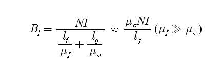
1차측과 2차측 코어 사이에 큰 공극이 있을 때 자속밀도는 수학식 3과 같다.The magnetic flux density is expressed by
(![]()
![]()
![]()
![]()
![]()
![]()
![]()
![]()
![]()
![]()
![]()
![]()
![]()
![]()
공극이 없을 경우의 자속밀도는 수학식 4와 같다. The magnetic flux density in the absence of voids is shown in

코어의 투자율이 공기중의 투자율에 비하여 무척 크고, 공극의 크기가 코어의 크기에 비해 상대적으로 크기 때문에, 공극이 없을 경우의 자속밀도는 공극이 클 때의 자속밀도에 비하여 매우 큰 값을 갖는다. 결과적으로, 큰 공극을 갖고 있 는 트랜스포머의 경우 코어 내부에서 포화상태가 발생하기 힘들며 국지적인 포화상태도 쉽게 발생하지 않는다. 그러므로, 코어의 형태에 있어서 좁은 단면이나 돌출부를 허용한다. 또한, 코어 내부의 자속밀도가 낮으므로 히스테리시스(hysteresis; 이력현상)에 의한 코어 손실도 작다.Since the permeability of the core is much larger than the permeability of air and the size of the pores is relatively large compared to the size of the core, the magnetic flux density in the absence of voids has a very large value compared to the magnetic flux density in the case of large voids. As a result, transformers with large voids are less likely to saturate within the core and local saturation is less likely. Therefore, narrow cross sections or protrusions are allowed in the form of the core. In addition, since the magnetic flux density inside the core is low, the core loss due to hysteresis is also small.
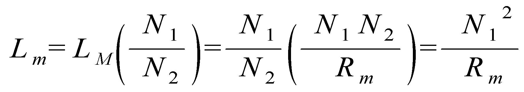
공극이 크기 때문에 자기저항이 증가하며, 결과적으로 코어의 인덕턴스는 감소한다. 그러므로, 요구하는 자화인덕턴스를 만들기 위해서는 권선수가 증가하여 결과적으로 넓은 권선영역이 필요하다. Due to the large voids, the magnetoresistance increases, and as a result, the inductance of the core decreases. Therefore, in order to make the required magnetizing inductance, the number of turns increases and consequently a wide winding area is required.
자화인덕턴스 ![]()
![]()
(![]()
![]()
![]()
![]()
![]()
![]()
![]()
![]()
즉, 자기저항 ![]()
![]()
![]()
![]()
대부분의 누설자속은 1차측과 2차측 코어 사이에 있는 공극에서 발생하므로, 공극이 있는 트랜스포머에서 결합계수를 높이기 위해서는 코어가 마주보는 단면적이 커야한다. 그런데 무접점 충전기에 사용되는 트랜스포머의 경우, 2차측 코어는 배터리팩 내부에 위치하기 때문에 부피와 무게에 한계가 있으므로, 마주보는 단면적의 넓이 또한 제한을 받는다. 그러나, 본원 발명에서는, 제한된 부피와 무게에서 마주보는 단면적이 큰 평판형 패드코어를 사용하였다. Most leakage fluxes occur in the air gap between the primary and secondary cores, so the cross section of the cores must be large in order to increase the coupling coefficient in the transformer with voids. However, in the case of a transformer used in a contactless charger, since the secondary core is located inside the battery pack, there is a limitation in volume and weight, so that the width of the cross section facing each other is also limited. However, in the present invention, a flat pad core having a large cross sectional area facing at a limited volume and weight is used.
도 8a 내지 도 8f는 본 발명에 따른 무선 충전용 패드에 구비되는 하프브리지(half-bridge) 직렬 공진형 컨버터의 각 모드별 동작을 나타낸 도면이다.8A to 8F are diagrams illustrating operations of respective modes of a half-bridge series resonant converter provided in the pad for wireless charging according to the present invention.
도 8a 내지 도 8f는 하프브리지 직렬 공진형 컨버터(상측 컨버터)의 각 모드별 동작을 나타낸다. 8A to 8F show the operation of each mode of the half-bridge series resonant converter (upper converter).
도 8a에서 ![]()
![]()
![]()
![]()
![]()
![]()
![]()
![]()
![]()
![]()
![]()
![]()
![]()
![]()
![]()
![]()
![]()
![]()
![]()
![]()
![]()
![]()
![]()
![]()
![]()
![]()
![]()
![]()
![]()
![]()
![]()
![]()
![]()
![]()
![]()
![]()
![]()
![]()
![]()
![]()
![]()
![]()
![]()
![]()
![]()
![]()
![]()
![]()
![]()
![]()
![]()
![]()
![]()
![]()
![]()
![]()
![]()
![]()
![]()
![]()
스위치 ![]()
![]()
![]()
![]()
![]()
![]()
![]()
![]()
![]()
![]()
여기서 공진주파수는 효율에 크게 영향을 미친다. 스위칭 주파수는 공진주파수 부근에서 동작하게 되므로 공진주파수가 낮으면 트랜스포머의 코어손실, 갭(gap)손실이 줄어든다. 그러나, 자화전류, 트랜스포머 1차측 전류가 증가하여 손실이 증가하는 측면도 있다. 따라서 공진주파수 보다 큰 스위칭주파수를 선택하여 영전압 스위칭에 의한 스위칭 손실을 저감할 수 있도록 설계한다.Here, the resonant frequency greatly affects the efficiency. Since the switching frequency operates near the resonance frequency, the lower the resonance frequency, the lower the core loss and the gap loss of the transformer. However, there are also aspects in which the loss increases because the magnetization current and the transformer primary side current increase. Therefore, it is designed to reduce switching loss by zero voltage switching by selecting switching frequency larger than resonance frequency.
도 9는 본 발명에 따른 무선 충전용 패드에 구비되는 하프브리지(half-bridge) 직렬 공진형 컨버터의 게이트 신호에 따른 트랜스포머의 전압, 전류 파형 을 나타낸 도면이다.FIG. 9 is a diagram illustrating voltage and current waveforms of a transformer according to a gate signal of a half-bridge series resonant converter provided in a pad for wireless charging according to the present invention.
도 9를 참조하면, 스위치 ![]()
![]()
![]()
![]()
![]()
![]()
도 10은 본 발명에 따른 무선 충전용 패드에 구비되는 하프브리지(half-bridge) 직렬 공진형 컨버터의 각 모드별 동작에 따른 자계의 회전 방향을 나타낸 도면이다.10 is a diagram illustrating a rotation direction of a magnetic field according to operation of each mode of a half-bridge series resonant converter provided in a pad for wireless charging according to the present invention.
도 10은 하프브리지 직렬 공진형 컨버터의 각 모드별 동작에 따라 발생된 자계의 회전방향을 나타낸다. 따라서 자계가 360도 회전을 하므로 충전 리시버 모듈(110)이 내장된 배터리팩(100)이 무선 충전용 패드(200) 위에 올려졌을 경우 놓인 위치와 방향에 관계없이 2차측에 유도기전력을 전달할 수 있게 된다.10 shows the rotation direction of the magnetic field generated by the operation of each mode of the half-bridge series resonant converter. Therefore, since the magnetic field rotates 360 degrees, when the
도 11a 내지 도 11d는 본 발명에 따른 충전 리시버 모듈의 정류회로를 나타낸 도면이다.11A to 11D illustrate a rectifier circuit of a charging receiver module according to the present invention.
도 11a 내지 도 11d를 참조하면, 2차측의 충전 리시버 모듈(110)은 1개의 센터탭(center-tap) 정류다이오드 출력과 출력 필터 커패시터를 사용한 직·병렬공진형 센터탭 하프브리지 정류회로를 통해 전력을 전달하거나, 풀브리지 정류다이오드 출력과 출력필터 커패시터를 사용한 직·병렬공진형 풀브리지 정류회로로 구현된 정류회로를 통해 전력을 전달한다.Referring to FIGS. 11A through 11D, the secondary
도 12는 본 발명에 따른 무선 충전용 패드에 구비되는 컨트롤러의 구성도이다.12 is a block diagram of a controller provided in the pad for wireless charging according to the present invention.
본 발명에 따른 무선 충전용 패드(200)에 구비되는 컨트롤러(240)는 배터리팩(100)이 올려졌는지를 판단하고, 배터리팩(100)이 올려져 있다면 배터리팩(100)으로부터 알에프아이디 태그(130)에 저장된 무선식별정보를 읽어 들여서, 충전해야 되는지 또는 몇 개의 배터리팩(100)이 올려져 있는지를 판단하여 드라이브 제어신호를 만들어 주기도 하며, 동시에 개별 배터리팩의 충전상태를 표시한다.The
도 12를 참조하면, 본 발명에 따른 무선 충전용 패드(200)에 구비되는 컨트롤러(240)는 소정 주파수의 발진신호를 발생시키는 오실레이터(241), 안테나 드라이버(242), 안테나 드라이버(242)로 수신된 알에프 데이터를 복조하는 디모듈레이터(243), 복조된 데이터에서 무선식별정보 및 충전상태정보를 필터링하여 증폭하는 필터 및 증폭부(244). 필터 및 증폭부(244)로부터 수신된 무선식별정보 및 충전상태정보를 복호화하는 데이터 디코더(245), 복호화된 데이터에 의해 충전상태에 따른 모드전환 등을 수행하기 위한 드라이버 제어부(246), 데이터 디코더(245)에서 디코딩된 데이터를 표시하는 디스플레이부(247), 타이머(248) 및 리셋부(249) 등으로 구성 가능하다.Referring to FIG. 12, the
안테나 드라이버(242)는 오실레이터(241)의 발진신호를 클럭(clock)으로 하고, 배터리팩(100)의 접근을 감시하며, 배터리팩(100)이 접근함에 따라 리더 안테 나(RA)를 통해 알에프 캐리어 신호에 대한 응답으로 배터리팩(100)의 무선식별정보 및 충전상태정보가 포함되어 변조된 알에프 데이터를 무선 수신한다. 이때, 안테나 드라이버(242)가 배터리팩(100)의 접근을 감시하는 방식으로는 리더 안테나(RA)를 통해 알에프 캐리어 신호를 주기적으로 외부에 무선 전송한 후 리턴(return)되는 신호 유무를 검사하는 폴링(polling) 방식이 적용될 수 있다.The
또한, 컨트롤러(240)는 다수개의 배터리팩(100)의 올려진 경우, 올려진 순서대로 각 배터리팩(100)의 무선식별정보 및 충전상태정보를 읽어들여 각각에 대한 충전상태를 표시하고, 모든 배터리팩(100)이 충전이 완료되어 만충상태가 되면 절전모드로 전환하는 기능을 구현한다.In addition, when the plurality of battery packs 100 are placed, the
도 13은 본 발명에 따른 무선 충전용 패드와 배터리팩 간의 알에프 신호(RF singnal) 흐름을 나타낸 도면이다.FIG. 13 is a view illustrating an RF singnal flow between a wireless charging pad and a battery pack according to the present invention.
도 12를 참조하면, 컨트롤러(240)가 충전 리시버 모듈(110)이 내장된 배터리팩(100)에서 알에프아이디 태그(130)에 HF(3~30MHz, high frequency, 단파) 또는 UHF(300~3000MHz, ultra high frequency, 극초단파) 대역의 캐리어 주파수로 배터리에 관한 정보를 엑세스(Access)하면 알에프아이디 태그(130)의 메모리 블록에 저장된 배터리정보를 변조된 알에프 신호(RF Signal)로 무선 충전용 패드(200)에 송신하는 구조로 되어있다.Referring to FIG. 12, the
상기 본 발명은 당업자의 요구에 따라 기본 개념을 벗어나지 않는 범위 내에 서 다양한 변형이 가능하다.The present invention can be variously modified within the scope without departing from the basic concept according to the needs of those skilled in the art.
상술한 바와 같이 본 발명에 따르면, 배터리팩의 충전 상태를 실시간으로 인지할 수 있고, 내부에 올려진 디바이스를 바로 검출할 수 있는 수단이 구현되어, 다수의 배터리팩이 무선 충전용 패드에 올려지거나 충전이 불가능한 이물질이 올려진 경우 등에 효율적인 대응을 가능케 하는 무선주파수 식별기술이 적용된 무선 충전용 패드 및 배터리팩이 제공되는 효과가 있다.As described above, according to the present invention, a means for recognizing a state of charge of a battery pack in real time and immediately detecting a device mounted therein is implemented, whereby a plurality of battery packs are placed on a wireless charging pad or There is an effect of providing a wireless charging pad and battery pack is applied to the radio frequency identification technology that enables efficient response, such as when the foreign matter is impossible to charge.
Claims (14)
Priority Applications (3)
| Application Number | Priority Date | Filing Date | Title |
|---|---|---|---|
| KR1020040048286A KR100564256B1 (en) | 2004-06-25 | 2004-06-25 | Wireless charging pads and battery packs with radio frequency identification technology |
| KR20040018212U KR200361755Y1 (en) | 2004-06-25 | 2004-06-28 | Wireless charging pad and battery pack applied radio frequency identification technology |
| PCT/KR2004/002263 WO2006001557A1 (en) | 2004-06-25 | 2004-09-07 | Wireless charging pad and battery pack using radio frequency identification technology |
Applications Claiming Priority (1)
| Application Number | Priority Date | Filing Date | Title |
|---|---|---|---|
| KR1020040048286A KR100564256B1 (en) | 2004-06-25 | 2004-06-25 | Wireless charging pads and battery packs with radio frequency identification technology |
Related Child Applications (1)
| Application Number | Title | Priority Date | Filing Date |
|---|---|---|---|
| KR20040018212U Division KR200361755Y1 (en) | 2004-06-25 | 2004-06-28 | Wireless charging pad and battery pack applied radio frequency identification technology |
Publications (2)
| Publication Number | Publication Date |
|---|---|
| KR20050122669A KR20050122669A (en) | 2005-12-29 |
| KR100564256B1 true KR100564256B1 (en) | 2006-03-29 |
Family
ID=35781948
Family Applications (2)
| Application Number | Title | Priority Date | Filing Date |
|---|---|---|---|
| KR1020040048286A Expired - Fee Related KR100564256B1 (en) | 2004-06-25 | 2004-06-25 | Wireless charging pads and battery packs with radio frequency identification technology |
| KR20040018212U Ceased KR200361755Y1 (en) | 2004-06-25 | 2004-06-28 | Wireless charging pad and battery pack applied radio frequency identification technology |
Family Applications After (1)
| Application Number | Title | Priority Date | Filing Date |
|---|---|---|---|
| KR20040018212U Ceased KR200361755Y1 (en) | 2004-06-25 | 2004-06-28 | Wireless charging pad and battery pack applied radio frequency identification technology |
Country Status (2)
| Country | Link |
|---|---|
| KR (2) | KR100564256B1 (en) |
| WO (1) | WO2006001557A1 (en) |
Cited By (8)
| Publication number | Priority date | Publication date | Assignee | Title |
|---|---|---|---|---|
| KR100976163B1 (en) * | 2009-06-19 | 2010-08-16 | 정춘길 | Wireless charging system using core structure for wireless power transmission and method using the same |
| KR100999770B1 (en) | 2007-02-20 | 2010-12-08 | 세이코 엡슨 가부시키가이샤 | Transmission Control Units, Transmission Units, Electronic Devices and Solid State Power Transmission Systems |
| KR101084904B1 (en) * | 2009-10-07 | 2011-11-18 | 삼성전기주식회사 | Wireless power transceiver with communication function and wireless power transmission / reception method thereof |
| KR101145682B1 (en) * | 2009-06-12 | 2012-05-24 | 정춘길 | Non-contact charging system for vehicle and charging control method thereof |
| KR101169185B1 (en) | 2009-04-22 | 2012-07-30 | 파나소닉 주식회사 | Non-contact power supply system |
| US8571609B2 (en) | 2010-01-15 | 2013-10-29 | Samsung Electronics Co., Ltd. | Wireless power transmission method |
| KR20160033383A (en) | 2014-09-18 | 2016-03-28 | 계명대학교 산학협력단 | Wireless charging led light apparatus and control method thereof |
| US10141979B2 (en) | 2011-05-17 | 2018-11-27 | Samsung Electronics Co., Ltd. | Apparatus and method for using near field communication and wireless power transmission |
Families Citing this family (90)
| Publication number | Priority date | Publication date | Assignee | Title |
|---|---|---|---|---|
| KR100603986B1 (en) | 2005-03-07 | 2006-07-25 | 주식회사 한림포스텍 | Battery pack for wireless charge |
| KR100554889B1 (en) * | 2005-03-21 | 2006-03-03 | 주식회사 한림포스텍 | Contactless charging system |
| US7495414B2 (en) * | 2005-07-25 | 2009-02-24 | Convenient Power Limited | Rechargeable battery circuit and structure for compatibility with a planar inductive charging platform |
| US11201500B2 (en) * | 2006-01-31 | 2021-12-14 | Mojo Mobility, Inc. | Efficiencies and flexibilities in inductive (wireless) charging |
| US8169185B2 (en) | 2006-01-31 | 2012-05-01 | Mojo Mobility, Inc. | System and method for inductive charging of portable devices |
| US7952322B2 (en) | 2006-01-31 | 2011-05-31 | Mojo Mobility, Inc. | Inductive power source and charging system |
| US7989986B2 (en) * | 2006-03-23 | 2011-08-02 | Access Business Group International Llc | Inductive power supply with device identification |
| US7355150B2 (en) | 2006-03-23 | 2008-04-08 | Access Business Group International Llc | Food preparation system with inductive power |
| US11245287B2 (en) | 2006-03-23 | 2022-02-08 | Philips Ip Ventures B.V. | Inductive power supply with device identification |
| US11329511B2 (en) | 2006-06-01 | 2022-05-10 | Mojo Mobility Inc. | Power source, charging system, and inductive receiver for mobile devices |
| US7948208B2 (en) | 2006-06-01 | 2011-05-24 | Mojo Mobility, Inc. | Power source, charging system, and inductive receiver for mobile devices |
| WO2008026080A2 (en) * | 2006-09-01 | 2008-03-06 | Bio Aim Technologies Holding Ltd. | Systems and methods for wireless power transfer |
| JP4650407B2 (en) * | 2006-12-12 | 2011-03-16 | ソニー株式会社 | Wireless processing system, wireless processing method, and wireless electronic device |
| US7793121B2 (en) | 2007-03-01 | 2010-09-07 | Eastman Kodak Company | Charging display system |
| KR100874837B1 (en) | 2007-07-09 | 2008-12-18 | 주식회사 한림포스텍 | Contactless charging system and control method |
| KR100819753B1 (en) * | 2007-07-13 | 2008-04-08 | 주식회사 한림포스텍 | Contactless charging system for battery pack solution and its control method |
| KR100971748B1 (en) * | 2007-11-30 | 2010-07-22 | 정춘길 | Short range wireless power transfer system |
| WO2009069844A1 (en) | 2007-11-30 | 2009-06-04 | Chun-Kil Jung | Multiple non-contact charging system of wireless power transmision and control method thereof |
| KR101011836B1 (en) | 2008-01-09 | 2011-01-31 | 세이코 엡슨 가부시키가이샤 | Power transmission controlling device, power transmission device, contactless power transmission system, and electronic equipment |
| KR100976161B1 (en) | 2008-02-20 | 2010-08-16 | 정춘길 | Contactless charging system and its charging control method |
| AU2009223084A1 (en) | 2008-03-13 | 2009-09-17 | Access Business Group International Llc | Inductive power supply system with multiple coil primary |
| KR20100130215A (en) | 2008-03-17 | 2010-12-10 | 파우워매트 엘티디. | Inductive transmission system |
| US20110050164A1 (en) | 2008-05-07 | 2011-03-03 | Afshin Partovi | System and methods for inductive charging, and improvements and uses thereof |
| US9178387B2 (en) | 2008-05-13 | 2015-11-03 | Qualcomm Incorporated | Receive antenna for wireless power transfer |
| US8981598B2 (en) | 2008-07-02 | 2015-03-17 | Powermat Technologies Ltd. | Energy efficient inductive power transmission system and method |
| US11979201B2 (en) | 2008-07-02 | 2024-05-07 | Powermat Technologies Ltd. | System and method for coded communication signals regulating inductive power transmissions |
| US8983554B2 (en) | 2008-07-15 | 2015-03-17 | Blackberry Limited | Mobile wireless communications device with RF immune charging contacts |
| US8315578B2 (en) | 2008-07-15 | 2012-11-20 | Research In Motion Limited | Mobile wireless communications device with separate in-phase and quadrature power amplification |
| US7932864B2 (en) | 2008-07-15 | 2011-04-26 | Research In Motion Limited | Mobile wireless communications device with antenna contact having reduced RF inductance |
| MY160103A (en) | 2008-10-03 | 2017-02-28 | Access Business Group Int Llc | Power system |
| WO2010067927A1 (en) | 2008-12-12 | 2010-06-17 | Jung Chun-Kil | Contactless charging station equipped with a ptps core having a planar spiral core structure, contactless power receiving apparatus, and method for controlling same |
| WO2010068062A2 (en) | 2008-12-12 | 2010-06-17 | 주식회사 한림포스텍 | Contactless power transmission device |
| RU2011132943A (en) * | 2009-01-06 | 2013-02-20 | Эксесс Бизнес Груп Интернешнл Ллс | WIRELESS CHARGING SYSTEM WITH ACCORDING TO THE POWER SUPPLY OF THE DEVICE |
| US8223885B2 (en) | 2009-02-19 | 2012-07-17 | Research In Motion Limited | Mobile wireless communications device with separate In-phase (I) and Quadrature (Q) phase power amplification and power amplifier pre-distortion and IQ balance compensation |
| US8655272B2 (en) * | 2009-07-07 | 2014-02-18 | Nokia Corporation | Wireless charging coil filtering |
| USD611898S1 (en) | 2009-07-17 | 2010-03-16 | Lin Wei Yang | Induction charger |
| USD611899S1 (en) | 2009-07-31 | 2010-03-16 | Lin Wei Yang | Induction charger |
| USD611900S1 (en) | 2009-07-31 | 2010-03-16 | Lin Wei Yang | Induction charger |
| US8427101B2 (en) | 2009-11-18 | 2013-04-23 | Nokia Corporation | Wireless energy repeater |
| DE102010011740A1 (en) * | 2010-03-17 | 2011-09-22 | Borgwarner Beru Systems Gmbh | Battery for electric vehicle |
| CN103109165B (en) | 2010-04-08 | 2015-08-19 | 捷通国际有限公司 | Point of sale sensing system and method |
| US8890470B2 (en) | 2010-06-11 | 2014-11-18 | Mojo Mobility, Inc. | System for wireless power transfer that supports interoperability, and multi-pole magnets for use therewith |
| KR101794348B1 (en) * | 2010-10-21 | 2017-11-07 | 삼성전자주식회사 | Apparatus and method for displaying power strength and expected charged time in performing wireless charging |
| KR101101766B1 (en) * | 2010-12-03 | 2012-01-05 | 주식회사 엘트로닉스 | Wireless energy receiving device and portable electronic device including same |
| JP2012143146A (en) * | 2011-01-03 | 2012-07-26 | Samsung Electronics Co Ltd | Wireless power transmission apparatus and wireless power transmission system thereof |
| JP2012143091A (en) * | 2011-01-04 | 2012-07-26 | Kimitake Utsunomiya | Remotely and wirelessly driven charger |
| US9496732B2 (en) | 2011-01-18 | 2016-11-15 | Mojo Mobility, Inc. | Systems and methods for wireless power transfer |
| US9178369B2 (en) | 2011-01-18 | 2015-11-03 | Mojo Mobility, Inc. | Systems and methods for providing positioning freedom, and support of different voltages, protocols, and power levels in a wireless power system |
| US9356659B2 (en) | 2011-01-18 | 2016-05-31 | Mojo Mobility, Inc. | Chargers and methods for wireless power transfer |
| US10115520B2 (en) | 2011-01-18 | 2018-10-30 | Mojo Mobility, Inc. | Systems and method for wireless power transfer |
| US11342777B2 (en) | 2011-01-18 | 2022-05-24 | Mojo Mobility, Inc. | Powering and/or charging with more than one protocol |
| KR101267076B1 (en) * | 2011-03-24 | 2013-05-24 | 주식회사 한림포스텍 | Power control method and wireless power transfer assembly in wireless power transfer assembly |
| KR101768723B1 (en) * | 2011-03-30 | 2017-08-17 | 삼성전자주식회사 | Method and system for wireless charging in a portable terminal |
| EP2858205A1 (en) * | 2011-04-08 | 2015-04-08 | Access Business Group International LLC | Counter wound inductive power supply |
| WO2012153975A2 (en) * | 2011-05-09 | 2012-11-15 | Kim Chang Ho | Contactless charging system having a standby-power cutoff function, and method for controlling same |
| KR101250266B1 (en) * | 2011-05-31 | 2013-04-03 | 주식회사 아울테크놀로지 | Wireless charger to charge battery of mobile comunication device having different capacity and method thereof |
| KR101802441B1 (en) * | 2011-11-17 | 2017-11-29 | 삼성전자주식회사 | Wireless energy receiving device, wireless energy transmitting device, wireless energy transmitting system including the same, and wireless energy transmitting method |
| US9391463B2 (en) | 2011-12-22 | 2016-07-12 | Hanrim Postech Co., Ltd. | Device and method for wirelessly transmitting power |
| US9722447B2 (en) | 2012-03-21 | 2017-08-01 | Mojo Mobility, Inc. | System and method for charging or powering devices, such as robots, electric vehicles, or other mobile devices or equipment |
| KR101381733B1 (en) * | 2012-05-25 | 2014-04-07 | 전자부품연구원 | System for Monitoring Crops based on Wireless Power Transmission |
| JP5718879B2 (en) | 2012-10-31 | 2015-05-13 | トヨタ自動車株式会社 | Vehicle parking assist device |
| US9837846B2 (en) | 2013-04-12 | 2017-12-05 | Mojo Mobility, Inc. | System and method for powering or charging receivers or devices having small surface areas or volumes |
| KR200475576Y1 (en) * | 2013-09-25 | 2014-12-12 | 한솔테크닉스(주) | The heat supporter of useing with WPC |
| US20150244200A1 (en) * | 2014-02-26 | 2015-08-27 | Mediatek Inc. | Method for performing wireless charging control of an electronic device with aid of frequency detection, and associated apparatus |
| WO2016135893A1 (en) * | 2015-02-25 | 2016-09-01 | 株式会社 東芝 | Control device, power transmission device, power reception device, wireless power transmission device, and control method |
| US10483783B2 (en) * | 2015-07-28 | 2019-11-19 | Motorola Solutions, Inc. | System and method for identifying a wirelessly charging battery |
| US10420175B2 (en) | 2015-09-25 | 2019-09-17 | Intel Corporation | Wireless warmers |
| KR20170053237A (en) | 2015-11-06 | 2017-05-16 | 엘지이노텍 주식회사 | Multi-Coil Wireless Charging Method and Apparatus and System therefor |
| CN106891743B (en) | 2015-12-18 | 2019-11-08 | 比亚迪股份有限公司 | Electric vehicle and its on-board charger and control method of on-board charger |
| US11303156B2 (en) | 2015-12-18 | 2022-04-12 | General Electric Company | Contactless power transfer system and method for controlling the same |
| CN106911191B (en) * | 2015-12-22 | 2020-05-22 | 比亚迪股份有限公司 | Wireless charging transmitter, wireless charging system and electric vehicle |
| CN105826066B (en) * | 2016-05-16 | 2019-02-22 | 上海墨百意信息科技有限公司 | A coil and inductance adjustment method applied to a wireless charging system |
| CN105978072B (en) * | 2016-06-06 | 2018-10-09 | 薛寿贞 | Wireless charging system |
| EP3280030B1 (en) | 2016-08-04 | 2023-08-30 | General Electric Company | System and method for charging receiver devices |
| US10615613B2 (en) * | 2016-11-09 | 2020-04-07 | Thames Technology Holdings, Inc. | Controllable charging systems and methods |
| CN110999029A (en) | 2017-05-30 | 2020-04-10 | 无线先进车辆电气化有限公司 | Single-point feed multi-pad wireless charging |
| US10389145B2 (en) | 2017-06-16 | 2019-08-20 | Witricity Corporation | System and method for reducing interference in a wireless power transfer system |
| US20190199115A1 (en) * | 2017-12-27 | 2019-06-27 | Newvastek Co., Ltd. | Wireless charging service system |
| US11462943B2 (en) | 2018-01-30 | 2022-10-04 | Wireless Advanced Vehicle Electrification, Llc | DC link charging of capacitor in a wireless power transfer pad |
| US11404910B2 (en) * | 2018-03-23 | 2022-08-02 | Raytheon Company | Multi-cell inductive wireless power transfer system |
| US11444485B2 (en) | 2019-02-05 | 2022-09-13 | Mojo Mobility, Inc. | Inductive charging system with charging electronics physically separated from charging coil |
| US11051248B2 (en) | 2019-03-06 | 2021-06-29 | Analog Devices International Unlimited Company | Radio-frequency wakeup for vehicle systems |
| BR112021019149A2 (en) * | 2019-03-27 | 2021-11-30 | Stryker Corp | System, method, and container for wirelessly sterilizing a rechargeable battery, containers configured to receive a battery and for sterilizing an object, method for removing sterile contents housed in a container, polymeric container, and, wirelessly rechargeable battery |
| US11063480B2 (en) * | 2019-05-28 | 2021-07-13 | Aira, Inc. | Adaptive passive Ping |
| KR102184838B1 (en) * | 2019-10-15 | 2020-12-02 | 아너스테크(주) | Automatic pet watering device for easy cleaning with wireless power supply |
| CN110994731B (en) * | 2019-12-20 | 2022-01-07 | Oppo广东移动通信有限公司 | Charging prompting method and device, electronic equipment and computer readable storage medium |
| US11525863B2 (en) * | 2021-02-11 | 2022-12-13 | GM Global Technology Operations LLC | Rechargeable energy storage system with radio frequency signal directing component and method of manufacturing |
| KR20220144232A (en) | 2021-04-19 | 2022-10-26 | 주식회사 소매드테크놀로지 | Wireless charger with separate wireless transmitting coil |
| CN114394004B (en) * | 2021-12-31 | 2023-08-22 | 南京信息工程大学 | Wireless charging device is shared to storage battery car |
| DE102023205800B4 (en) * | 2023-06-21 | 2025-06-12 | Infineon Technologies Ag | SUPPORTING STRUCTURE |
Citations (2)
| Publication number | Priority date | Publication date | Assignee | Title |
|---|---|---|---|---|
| KR20030042764A (en) * | 2001-11-23 | 2003-06-02 | 주식회사 엘지이아이 | Structure for preventing heat of globe in plasma lighting system |
| KR100539013B1 (en) * | 2005-06-03 | 2005-12-26 | 주식회사 린포스 | A wireless mouse charging with induction coil |
Family Cites Families (7)
| Publication number | Priority date | Publication date | Assignee | Title |
|---|---|---|---|---|
| JP3344593B2 (en) * | 1992-10-13 | 2002-11-11 | 株式会社ソニー木原研究所 | Wireless power supply |
| JP2671809B2 (en) * | 1994-06-30 | 1997-11-05 | 日本電気株式会社 | Non-contact charging device |
| JPH09233706A (en) * | 1996-02-21 | 1997-09-05 | Hitachi Ltd | Contactless charger |
| JPH10201113A (en) * | 1996-12-27 | 1998-07-31 | Oki Electric Ind Co Ltd | Multifunctional charger for digital cordless system |
| JPH1168837A (en) * | 1997-08-20 | 1999-03-09 | Hitachi Ltd | Incoming call forwarding in packet-switched networks over IP networks |
| JPH11178232A (en) * | 1997-12-16 | 1999-07-02 | Canon Inc | Contactless rechargeable electronic devices |
| JP2002272020A (en) * | 2001-03-09 | 2002-09-20 | Sony Corp | Non-contact power transmission device and non-contact charging device |
-
2004
- 2004-06-25 KR KR1020040048286A patent/KR100564256B1/en not_active Expired - Fee Related
- 2004-06-28 KR KR20040018212U patent/KR200361755Y1/en not_active Ceased
- 2004-09-07 WO PCT/KR2004/002263 patent/WO2006001557A1/en not_active Ceased
Patent Citations (2)
| Publication number | Priority date | Publication date | Assignee | Title |
|---|---|---|---|---|
| KR20030042764A (en) * | 2001-11-23 | 2003-06-02 | 주식회사 엘지이아이 | Structure for preventing heat of globe in plasma lighting system |
| KR100539013B1 (en) * | 2005-06-03 | 2005-12-26 | 주식회사 린포스 | A wireless mouse charging with induction coil |
Non-Patent Citations (2)
| Title |
|---|
| 1005390130000 |
| 2003427640000 |
Cited By (8)
| Publication number | Priority date | Publication date | Assignee | Title |
|---|---|---|---|---|
| KR100999770B1 (en) | 2007-02-20 | 2010-12-08 | 세이코 엡슨 가부시키가이샤 | Transmission Control Units, Transmission Units, Electronic Devices and Solid State Power Transmission Systems |
| KR101169185B1 (en) | 2009-04-22 | 2012-07-30 | 파나소닉 주식회사 | Non-contact power supply system |
| KR101145682B1 (en) * | 2009-06-12 | 2012-05-24 | 정춘길 | Non-contact charging system for vehicle and charging control method thereof |
| KR100976163B1 (en) * | 2009-06-19 | 2010-08-16 | 정춘길 | Wireless charging system using core structure for wireless power transmission and method using the same |
| KR101084904B1 (en) * | 2009-10-07 | 2011-11-18 | 삼성전기주식회사 | Wireless power transceiver with communication function and wireless power transmission / reception method thereof |
| US8571609B2 (en) | 2010-01-15 | 2013-10-29 | Samsung Electronics Co., Ltd. | Wireless power transmission method |
| US10141979B2 (en) | 2011-05-17 | 2018-11-27 | Samsung Electronics Co., Ltd. | Apparatus and method for using near field communication and wireless power transmission |
| KR20160033383A (en) | 2014-09-18 | 2016-03-28 | 계명대학교 산학협력단 | Wireless charging led light apparatus and control method thereof |
Also Published As
| Publication number | Publication date |
|---|---|
| KR20050122669A (en) | 2005-12-29 |
| WO2006001557A1 (en) | 2006-01-05 |
| KR200361755Y1 (en) | 2004-09-14 |
Similar Documents
| Publication | Publication Date | Title |
|---|---|---|
| KR100564256B1 (en) | Wireless charging pads and battery packs with radio frequency identification technology | |
| US11018531B2 (en) | Receiver for wireless charging system | |
| CN100362725C (en) | Contactless Charging System | |
| CN102906828B (en) | Iron core assembly for wireless power communication and power supply device for wireless power communication | |
| KR101250266B1 (en) | Wireless charger to charge battery of mobile comunication device having different capacity and method thereof | |
| KR101622694B1 (en) | Wireless power transfer method, apparatus and system | |
| KR101613956B1 (en) | Wireless power transfer method, apparatus and system | |
| WO2015065810A1 (en) | Systems, apparatus, and method for a dual mode wireless power receiver | |
| KR100595702B1 (en) | Wireless charging pad and battery pack for two-way charging | |
| KR20190093937A (en) | Wireless Power Receiver For Enhancing Antenna Performance | |
| KR100543779B1 (en) | Portable terminal with built-in battery pack and built-in battery pack with radio frequency identification technology | |
| KR100564255B1 (en) | Contactless rechargeable battery pack, wireless charging method between these battery packs and system | |
| KR100643941B1 (en) | Integrated circuit for processing battery information and integrated circuit for wireless charging | |
| KR101136917B1 (en) | Wireless charger and charging method | |
| KR20190077836A (en) | Wireless Charging Apparatus With Enhanced Quality Factor | |
| KR20190076517A (en) | Wireless Charging Apparatus With Enhanced Quality Factor | |
| KR102548981B1 (en) | Apparatus for receiving wireless power | |
| KR20180013088A (en) | Wireless Power Transmitter and Wireless Power Receiver |
Legal Events
| Date | Code | Title | Description |
|---|---|---|---|
| A201 | Request for examination | ||
| PA0109 | Patent application |
St.27 status event code: A-0-1-A10-A12-nap-PA0109 |
|
| PA0201 | Request for examination |
St.27 status event code: A-1-2-D10-D11-exm-PA0201 |
|
| P11-X000 | Amendment of application requested |
St.27 status event code: A-2-2-P10-P11-nap-X000 |
|
| P13-X000 | Application amended |
St.27 status event code: A-2-2-P10-P13-nap-X000 |
|
| PG1501 | Laying open of application |
St.27 status event code: A-1-1-Q10-Q12-nap-PG1501 |
|
| E701 | Decision to grant or registration of patent right | ||
| PE0701 | Decision of registration |
St.27 status event code: A-1-2-D10-D22-exm-PE0701 |
|
| GRNT | Written decision to grant | ||
| PR0701 | Registration of establishment |
St.27 status event code: A-2-4-F10-F11-exm-PR0701 |
|
| PR1002 | Payment of registration fee |
St.27 status event code: A-2-2-U10-U11-oth-PR1002 Fee payment year number: 1 |
|
| PG1601 | Publication of registration |
St.27 status event code: A-4-4-Q10-Q13-nap-PG1601 |
|
| PN2301 | Change of applicant |
St.27 status event code: A-5-5-R10-R13-asn-PN2301 St.27 status event code: A-5-5-R10-R11-asn-PN2301 |
|
| PR1001 | Payment of annual fee |
St.27 status event code: A-4-4-U10-U11-oth-PR1001 Fee payment year number: 4 |
|
| PR1001 | Payment of annual fee |
St.27 status event code: A-4-4-U10-U11-oth-PR1001 Fee payment year number: 5 |
|
| R17-X000 | Change to representative recorded |
St.27 status event code: A-5-5-R10-R17-oth-X000 |
|
| PR1001 | Payment of annual fee |
St.27 status event code: A-4-4-U10-U11-oth-PR1001 Fee payment year number: 6 |
|
| FPAY | Annual fee payment |
Payment date: 20120321 Year of fee payment: 7 |
|
| PR1001 | Payment of annual fee |
St.27 status event code: A-4-4-U10-U11-oth-PR1001 Fee payment year number: 7 |
|
| R18-X000 | Changes to party contact information recorded |
St.27 status event code: A-5-5-R10-R18-oth-X000 |
|
| FPAY | Annual fee payment |
Payment date: 20121226 Year of fee payment: 8 |
|
| PR1001 | Payment of annual fee |
St.27 status event code: A-4-4-U10-U11-oth-PR1001 Fee payment year number: 8 |
|
| LAPS | Lapse due to unpaid annual fee | ||
| PC1903 | Unpaid annual fee |
St.27 status event code: A-4-4-U10-U13-oth-PC1903 Not in force date: 20140321 Payment event data comment text: Termination Category : DEFAULT_OF_REGISTRATION_FEE |
|
| PC1903 | Unpaid annual fee |
St.27 status event code: N-4-6-H10-H13-oth-PC1903 Ip right cessation event data comment text: Termination Category : DEFAULT_OF_REGISTRATION_FEE Not in force date: 20140321 |
|
| P22-X000 | Classification modified |
St.27 status event code: A-4-4-P10-P22-nap-X000 |
|
| P22-X000 | Classification modified |
St.27 status event code: A-4-4-P10-P22-nap-X000 |
|
| P22-X000 | Classification modified |
St.27 status event code: A-4-4-P10-P22-nap-X000 |