KR100258933B1 - Memory Management Device and Method - Google Patents
Memory Management Device and Method Download PDFInfo
- Publication number
- KR100258933B1 KR100258933B1 KR1019970032914A KR19970032914A KR100258933B1 KR 100258933 B1 KR100258933 B1 KR 100258933B1 KR 1019970032914 A KR1019970032914 A KR 1019970032914A KR 19970032914 A KR19970032914 A KR 19970032914A KR 100258933 B1 KR100258933 B1 KR 100258933B1
- Authority
- KR
- South Korea
- Prior art keywords
- register
- memory block
- memory
- block
- blocks
- Prior art date
- Legal status (The legal status is an assumption and is not a legal conclusion. Google has not performed a legal analysis and makes no representation as to the accuracy of the status listed.)
- Expired - Fee Related
Links
Images


Classifications
-
- G—PHYSICS
- G06—COMPUTING OR CALCULATING; COUNTING
- G06F—ELECTRIC DIGITAL DATA PROCESSING
- G06F12/00—Accessing, addressing or allocating within memory systems or architectures
- G06F12/02—Addressing or allocation; Relocation
- G06F12/0223—User address space allocation, e.g. contiguous or non contiguous base addressing
-
- G—PHYSICS
- G06—COMPUTING OR CALCULATING; COUNTING
- G06F—ELECTRIC DIGITAL DATA PROCESSING
- G06F13/00—Interconnection of, or transfer of information or other signals between, memories, input/output devices or central processing units
- G06F13/14—Handling requests for interconnection or transfer
- G06F13/16—Handling requests for interconnection or transfer for access to memory bus
Landscapes
- Engineering & Computer Science (AREA)
- Theoretical Computer Science (AREA)
- Physics & Mathematics (AREA)
- General Engineering & Computer Science (AREA)
- General Physics & Mathematics (AREA)
- Complex Calculations (AREA)
Abstract
본 발명은 메모리 관리 장치 및 방법에 관한 것으로서, 복수개의 메모리 블록들을 서로 링크하고 상기 각 메모리 블록마다 소정의 번호를 부여하여 사용하는 메모리부; 상기 메모리 블록들중에서 색인할 한 메모리 블록의 번호를 저장하는 제1레지스터; 상기 메모리 블록들중 마지막 링크된 메모리 블록의 번호를 저장하는 제2레지스터; 다수의 데이터가 병렬 처리되고, 상기 각 메모리 블록의 사용 유무 상태를 나타내는 한 개의 상태 비트가 저장된 제3레지스터; 및 상기 제1레지스터와 제2레지스터에 저장된 내용을 읽어 색인할 메모리 블록을 결정하고, 상기 제3레지스터에서 상기 메모리 블록에 대한 상기 상태 비트를 읽어 상기 색인할 메모리 블록이 사용 가능한지를 판단하여 그에 따라 메모리를 억세스하는 제어부를 포함함을 특징으로 한다.The present invention relates to a memory management apparatus and method, comprising: a memory unit for linking a plurality of memory blocks with each other and assigning a predetermined number to each of the memory blocks; A first register storing a number of one memory block to be indexed among the memory blocks; A second register for storing a number of the last linked memory block of the memory blocks; A third register in which a plurality of pieces of data are processed in parallel and one status bit indicating whether each memory block is in use or not; And a memory block to read and store contents stored in the first and second registers, and determine whether a memory block to be indexed is available by reading the status bits for the memory block in the third register. And a control unit for accessing the memory.
본 발명에 의하면, 해당 메모리 블록이 사용 가능한지 가능하지 않는지의 정보를 담은 상태 비트들의 정보를 가진 벡터 레지스터를 사용함으로써 메모리 억세스 횟수를 줄일 수 있다.According to the present invention, the number of memory accesses can be reduced by using a vector register having information of status bits containing information of whether a corresponding memory block is available or not.
Description
본 발명은 메모리 관리 장치 및 그 방법에 관한 것으로서, 보다 상세하게는 다수개의 기억소자들로 구성된 벡터 레지스터를 이용하여 여러개의 균등한 저용량의 메모리 블록들을 관리하는 메모리 관리 장치 및 방법에 관한 것이다.The present invention relates to a memory management apparatus and a method thereof, and more particularly, to a memory management apparatus and method for managing a plurality of equally low-capacity memory blocks using a vector register composed of a plurality of memory elements.
종래에는 도 1의 메모리부 구성도에 도시된 바와 같이 다수의 균등한 저용량 메모리 블록들에 대해 각 메모리 블록에 상태 비트를 두어 그 내용에 따라 해당 메모리 블록이 사용가능한지 불가능한지 또는 사용중인지를 알 수 있도록 하였다. 이것은 도면에 도시되지 않은 레지스터를 두어 메모리 블록 사용할 때에 각 메모리 블록의 상태 비트를 레지스터에 억세스한 후 그 내용을 읽음으로써 구현되었다.Conventionally, as shown in the memory block diagram of FIG. 1, a status bit is placed in each memory block for a plurality of equally low-capacity memory blocks to determine whether the corresponding memory block is available, unavailable or in use. It was made. This is implemented by reading the contents after accessing the registers with the status bits of each memory block when using a memory block by placing a register not shown in the figure.
상술한 바와 같은 메모리 블록 관리에 있어서, 메모리 블록이 사용될 때마다 메모리 억세스를 하여 상태 비트를 점검한 후 다른 메모리 블록들을 트래버설해야 하기 때문에 관련 시스템에 있어서 속도 문제를 포함하여 이 시스템 전반의 성능 저하를 가져오는 문제가 발생한다.In the above-described memory block management, every time a memory block is used, memory access must be performed to check status bits and then traverse other memory blocks, thereby reducing overall system performance including speed problems in the related system. The problem arises.
본 발명이 이루고자하는 기술적 과제는 메모리 블록의 사용 가능 상태를 알리는 상태 비트를 벡터 레지스터에 저장하여 빈번한 메모리 억세스를 필요로 하지 않아도 되는 메모리 블록 관리 장치 및 방법을 제공하는데 있다.An object of the present invention is to provide an apparatus and method for managing a memory block which does not require frequent memory access by storing a status bit indicating a usable state of a memory block in a vector register.
도 1은 종래의 메모리부의 구성을 도시한 것이다.1 illustrates a configuration of a conventional memory unit.
도 2는 본 발명에 따른 메모리 관리 장치의 블록도이다.2 is a block diagram of a memory management apparatus according to the present invention.
도 3은 본 발명에 따른 메모리 관리 방법의 흐름도이다.3 is a flowchart of a memory management method according to the present invention.
상기 과제를 위한 메모리 관리 장치는, 복수개의 메모리 블록들을 서로 링크하고 상기 각 메모리 블록마다 소정의 번호를 부여하여 사용하는 메모리부; 상기 메모리 블록들중에서 색인할 한 메모리 블록의 번호를 저장하는 제1레지스터; 상기 메모리 블록들중 마지막 링크된 메모리 블록의 번호를 저장하는 제2레지스터; 다수의 데이터가 병렬 처리되고, 상기 각 메모리 블록의 사용 유무 상태를 나타내는 한 개의 상태 비트가 저장된 제3레지스터; 및 상기 제1레지스터와 제2레지스터에 저장된 내용을 읽어 색인할 메모리 블록을 결정하고, 상기 제3레지스터에서 상기 메모리 블록에 대한 상기 상태 비트를 읽어 상기 색인할 메모리 블록이 사용 가능한지를 판단하여 그에 따라 메모리를 억세스하는 제어부를 포함함을 특징으로 한다.The memory management apparatus for the above problem comprises: a memory unit for linking a plurality of memory blocks with each other and assigning a predetermined number to each of the memory blocks; A first register storing a number of one memory block to be indexed among the memory blocks; A second register for storing a number of the last linked memory block of the memory blocks; A third register in which a plurality of pieces of data are processed in parallel and one status bit indicating whether each memory block is in use or not; And a memory block to read and store contents stored in the first and second registers, and determine whether a memory block to be indexed is available by reading the status bits for the memory block in the third register. And a control unit for accessing the memory.
상기 다른 과제를 위한, 복수개의 메모리 블록들이 서로 링크된 메모리부, 상기 메모리 블록들을 구분하기 위한 블록 번호들중에 색인할 메모리 블록 번호를 저장하는 제1레지스터, 상기 메모리 블록중에 마지막 메모리 블록의 번호를 저장하는 제2레지스터, 다수의 레지스터로들로 되어 각 레지스터마다 상기 메모리 블록의 사용 상태를 나타내는 상태 비트가 쓰여진 제3레지스터 및 상기 제1, 제2, 제3레지스터를 읽고 메모리부를 억세스하는 제어부를 구비하는 시스템의 메모리 관리 방법에 있어서, 상기 제1레지스터와 제3레지스터를 초기화하고 상기 제2레지스터에 상기 메모리부의 최종 메모리 블록의 번호를 저장 하는 제1단계; 상기 제1단계의 상기 제1레지스터의 내용이 상기 제2레지스터의 최종 메모리 블록 번호보다 작거나 같으면 상기 제1레지스터에 기록된 메모리 블록 번호에 대한 상기 제3레지스터의 상태 비트를 읽는 제2단계;For the another object, a first register for storing a memory block number to be indexed among the memory unit to which the plurality of memory blocks are linked to each other, the block number for distinguishing the memory blocks, the number of the last memory block in the memory block A second register for storing, a third register having a plurality of registers, in which a status bit indicating a usage state of the memory block is written for each register, and a control unit for reading the first, second, and third registers, and accessing the memory unit. A memory management method of a system comprising: a first step of initializing the first register and the third register and storing the number of the last memory block of the memory unit in the second register; Reading a status bit of the third register with respect to the memory block number written in the first register if the content of the first register in the first step is less than or equal to the last memory block number of the second register;
상기 제1단계의 상기 제1레지스터의 내용이 제2레지스터에 저장된 메모리 블록 번호보다 크면 제1레지스터의 내용을 초기화 시키는 제3단계; 상기 제2단계의 상기 제3레지스터의 상태 비트를 읽어 해당 메모리 블록이 인에이블한지를 판단하는 제4단계; 상기 제4단계에서 상기 해당 메모리 블록이 인에이블 상태이면 상기 제1레지스터에 있는 색인할 메모리 블록 번호로 사용할 메모리 블록의 시작 어드레스를 산출하는 제5단계; 상기 제4단계에서 상기 해당 메모리 블록이 디세이블 상태이거나 상기 메모리 블록 사용이 종료되면 그 메모리 블록에 링크된 다음 메모리 블록의 번호를 제1레지스터에 쓰고, 사용이 종료된 메모리 블록에 대해 상기 제3레지스터에서 상기 메모리 블록의 상태 비트를 디세이블하는 제6단계; 및 다른 메모리 블록을 사용하기 위해 상기 제2단계부터 다시 수행하는 제7단계를 포함함을 특징으로 한다.A third step of initializing contents of the first register when the contents of the first register in the first stage are larger than the memory block number stored in the second register; A fourth step of determining whether a corresponding memory block is enabled by reading the status bits of the third register of the second step; Calculating a start address of a memory block to be used as a memory block number to be indexed in the first register when the corresponding memory block is enabled in the fourth step; In the fourth step, when the corresponding memory block is in a disabled state or when the use of the memory block ends, the number of the next memory block linked to the memory block is written to the first register, and the third memory block is used for the used memory block. Disabling a status bit of the memory block in a register; And a seventh step of performing the second step again to use another memory block.
이하에서 첨부된 도면을 참조하여 본 발명을 상세히 설명한다.Hereinafter, the present invention will be described in detail with reference to the accompanying drawings.
도 2는 본 발명에 따른 메모리 관리 장치의 블록도로서, 제어부(200), 메모리부(210), 제1레지스터(220), 제2 지스터(230) 및 벡터 레지스터(240)로 구성된다. 제어부(200)는 메모리를 운영 및 관리하는 주체이며, 메모리 관리를 위한 소정의 알고리즘을 포함한다. 메모리부(210)는 복수개의 서로 동일한 저용량의 메모리 블록들로 이루어지며, 각 메모리 블록들은 서로 동일한 크기이고 각자 차례로 메모리 블록 번호가 부여된다. 제1레지스터(220)는 통상의 구조를 가진 레지스터로서 메모리부(210)의 메모리 블록들중에서 곧 색인할 메모리 블록의 번호가 기억/저장된다. 제2레지스터(230)는 제1레지스터(220)와 동일한 구조의 통상의 한 데이터 저장 레지스터로서 메모리부(210)의 마지막 메모리 블록의 번호를 항시 저장한다. 벡터 레지스터(240)는 통상의 레지스터와는 달리 소정의 개수의 데이터가 함께 병렬로 입출력 및 저장될 수 있는 다수의 레지스터로 되고 각 레지스터간의 데이터 이동은 허용되지 않는 레지스터로서, 도 1에서 해당 메모리 블록이 자신의 사용 상태를 알 수 있도록 한 상태 비트들을 포함하고 있던것과는 달리 본 발명에서는 벡터 레지스터(240)가 메모리 블록들의 사용 여부 상태를 나타내는 상태 비트를 포함한다. 따라서 제어부(200)가 종래와 같이 메모리부를 직접 억세스하여 메모리 블록들의 사용 여부를 알 수 있었던 것과는 달리 벡터 레지스터(240)만를 읽어 그것을 알 수 있게 된다.2 is a block diagram of a memory management apparatus according to the present invention, and includes a
도 3은 본 발명에 따른 메모리 관리 방법의 흐름도를 도시한 것이다. 먼저 메모리부(210)를 사용하기 위해 처음에 제1레지스터(220)와 벡터 레지스터(240)의 내용을 소정의 내용으로 초기화한다(300단계). 이 때 제1레지스터(220)와 벡터 레지스터(240)의 초기화는, 상기 제1레지스터에 상기 메모리 블록들중에 첫 번째로 억세스되도록 링크된 블록의 번호를 쓰고 상기 벡터 레지스터에는 상기 각 레지스터 모두에 상기 메모리 블록이 인에이블 상태, 즉 '사용 가능' 상태임을 가리키도록 상태 비트를 세트하는 것이다. 그리고 나서 제2레지스터(230)에 메모리부(210)의 최종 메모리 블록의 번호를 기억/저장 시킨다(310단계). 제1레지스터(220)와 제2레지스터(230)의 내용의 크기를 비교하여(320단계) 제2레지스터(230)에 기록된 마지막 메모리 블록의 번호보다 제1레지스터(220)에 기록된 색인할 메모리 블록의 번호가 작거나 같으면 제1레지스터(220)에 기록된 메모리 블록 번호에 대응되는 메모리 블록의 상태 비트가 든 벡터 레지스터(240)를 읽는다(330단계). 만약 제1레지스터(220)에 저장된 메모리 블록 번호보다 제2레지스터(230)에 저장된 메모리 블록 번호가 더 작으면 제1레지스터(220)의 내용을 다시 상술한 300단계에서의 내용으로 초기화 시킨다(340단계). 벡터 레지스터(240)에 기록된, 해당 번호에 대응되는 메모리 블록의 상태 비트를 읽어 상태 비트가 인에이블이면 해당 메모리 블록이 사용 가능하다고 판단하고 디세이블이면 사용 불가능하다고 판단한다(350단계). 사용 가능하면 상술한 제1레지스터(220)에 있는 색인할 메모리 블록 번호를 이용하여 사용할 메모리 블록의 시작 어드레스를 다음의 수학식 1과 같이 산출한다(360단계).3 is a flowchart illustrating a memory management method according to the present invention. First, in order to use the
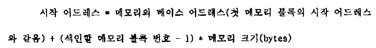
상술한 상태 비트를 읽어 해당 메모리 블록 사용이 불가능하다고 판단되거나 상술한 메모리 블록 사용을 마치면 제1레지스터(220)에 기록된 색인할 메모리 블록 번호를 링크된 순서가 다음인 메모리 블록의 번호로 변경하고(370단계) 벡터 레지스터(240)에 있는 막 사용을 마친 메모리 블록의 상태 비트를 그 메모리 블록이 '사용 불가' 상태임을 나타내도록 디세이블한다(380단계). 한 메모리 블록 사용을 마치거나 사용하고자 한 메모리 블록의 상태가 디세이블이면 다른 메모리 블록을 사용하기 위해 제1레지스터(220)와 제2레지스터(230)의 내용의 크기를 비교하는(320단계) 단계부터 다시 차례로 수행한다.If it is determined that the corresponding memory block is not available by reading the above-described status bit or when the above-mentioned memory block is finished, the memory block number to be indexed written in the
이하에서 예를 들어 본 발명의 동작을 설명한다. 메모리부(210)를 사용하고자 할 때, 먼저 제어부(200)는 제1레지스터(220)와 벡터 레지스터(240)를 초기화 하는데(300단계) 이것은, 제1레지스터(220)에는 메모리부(210)의 첫 메모리 블록 번호를 기록하고 벡터 레지스터(240)에는 '사용 가능'의 의미를 가지는 소정의 내용을 포함하도록 모든 메모리 블록의 사용 여부를 나타내는 상태 비트들을 설정시켜 놓는 것을 말한다. 여기서는 예를 들어 '1'을 초기치로서 제1레지스터(220)에 설정하여 저장시킨다. 또한 제2레지스터(230)에 메모리부(210)를 구성하는 최종 메모리 블록의 번호를 기억시킨다(310단계). 예를 들어 최종 메모리 블록 번호가 '8'이면 제2 레지스터(230)에는 '8'이 저장된다. 사용할 메모리 블록을 색인 하기 위해 제어부(200)는 제1레지스터(220)와 제2레지스터(230) 내용의 크기를 비교하는데(320단계) 상술한 예에서 제1레지스터(220)의 내용이 제2레지스터(230)의 내용보다 작으므로 제1레지스터(220)에 기록된 색인할 메모리 블록 번호에 대응되는, 즉 벡터 레지스터(240)에 있는, 메모리 블록 번호 '1'에 대응되는 레지스터의 상태 비트를 읽는다(330단계). 그 상태 비트가 '사용 가능'의 의미로 쓰여져 있으면 제1레지스터(220)에 있는 메모리 블록의 번호를 이용하여 사용할 메모리 블록의 시작 어드레스를 상술한 수학식 1과 같이 산출하여 해당 메모리 블록인 '1'번 메모리 블록의 시작 어드레스부터 억세스 하는 식으로 메모리를 사용한다(360단계). 제어부(200)는 제1레지스터(220)에 기록된 색인할 메모리 블록 번호를 증가시키는데(370단계) 그 증가한 값은 막 사용한 메모리 블록과 이어져 링크된 바로 다음 메모리 블록의 번호가 된다. 벡터 레지스터(240)에 있는 막 사용을 마친 메모리 블록의 상태 비트를 디세이블하여(380단계) 누군가 이 메모리 블록으로의 억세스를 막는다. 다시 다음 메모리 블록을 억세스 하기위해 상술한 제1레지스터(220)와 제2 레지스터(230)의 내용의 크기를 비교하는 것(320단계)부터 상술한 단계부터 차례로 반복 수행한다.For example, the operation of the present invention will be described below. When the
본 발명에 의하면 해당 메모리 블록이 사용 가능한지 가능하지 않는지의 정보를 담은 상태 비트들의 정보를 가진 벡터 레지스터를 사용함으로써 메모리 억세스 횟수를 줄일 수 있다.According to the present invention, the number of memory accesses can be reduced by using a vector register having information of status bits containing information of whether a corresponding memory block is available or not.
Claims (6)
Priority Applications (1)
| Application Number | Priority Date | Filing Date | Title |
|---|---|---|---|
| KR1019970032914A KR100258933B1 (en) | 1997-07-15 | 1997-07-15 | Memory Management Device and Method |
Applications Claiming Priority (1)
| Application Number | Priority Date | Filing Date | Title |
|---|---|---|---|
| KR1019970032914A KR100258933B1 (en) | 1997-07-15 | 1997-07-15 | Memory Management Device and Method |
Publications (2)
| Publication Number | Publication Date |
|---|---|
| KR19990010216A KR19990010216A (en) | 1999-02-05 |
| KR100258933B1 true KR100258933B1 (en) | 2000-06-15 |
Family
ID=19514564
Family Applications (1)
| Application Number | Title | Priority Date | Filing Date |
|---|---|---|---|
| KR1019970032914A Expired - Fee Related KR100258933B1 (en) | 1997-07-15 | 1997-07-15 | Memory Management Device and Method |
Country Status (1)
| Country | Link |
|---|---|
| KR (1) | KR100258933B1 (en) |
-
1997
- 1997-07-15 KR KR1019970032914A patent/KR100258933B1/en not_active Expired - Fee Related
Also Published As
| Publication number | Publication date |
|---|---|
| KR19990010216A (en) | 1999-02-05 |
Similar Documents
| Publication | Publication Date | Title |
|---|---|---|
| US4926314A (en) | Method and apparatus for determining available memory size | |
| US8437190B2 (en) | Interleaved flash storage system and method | |
| KR0121800B1 (en) | Memory card device | |
| US7873763B2 (en) | Multi-reader multi-writer circular buffer memory | |
| CN113094003B (en) | Data processing method, data storage device and electronic equipment | |
| US6742078B1 (en) | Management, data link structure and calculating method for flash memory | |
| US20050055532A1 (en) | Method for efficiently controlling read/write of flash memory | |
| US8429339B2 (en) | Storage device utilizing free pages in compressed blocks | |
| US5003506A (en) | Memory capacity detection apparatus and electronic applied measuring device employing the same | |
| US4027288A (en) | Self-managing variable field storage system for handling nested data structures | |
| US4368532A (en) | Memory checking method | |
| RU2002118114A (en) | Computer device using non-renewable random access dynamic memory | |
| US11645202B2 (en) | Parsing method, parsing apparatus, electronic device, and computer storage medium | |
| KR100258933B1 (en) | Memory Management Device and Method | |
| US7409527B2 (en) | Bidirectional data storing method | |
| CN112068948B (en) | Data hashing method, readable storage medium and electronic device | |
| AU616653B2 (en) | Method and apparatus for determining available memory size | |
| KR102721579B1 (en) | Processing system | |
| CN112148203B (en) | Memory management method, device, electronic equipment and storage medium | |
| CN111435285B (en) | Data writing method and device for storage volume, electronic equipment and machine-readable storage medium | |
| US6742077B1 (en) | System for accessing a memory comprising interleaved memory modules having different capacities | |
| US7213142B2 (en) | System and method to initialize registers with an EEPROM stored boot sequence | |
| CN120909957B (en) | Data writing method and electronic equipment | |
| CN118821245B (en) | Write protection mapping method, device, computer readable storage medium and electronic device | |
| JPH05258585A (en) | Filing device |
Legal Events
| Date | Code | Title | Description |
|---|---|---|---|
| A201 | Request for examination | ||
| PA0109 | Patent application |
St.27 status event code: A-0-1-A10-A12-nap-PA0109 |
|
| PA0201 | Request for examination |
St.27 status event code: A-1-2-D10-D11-exm-PA0201 |
|
| R17-X000 | Change to representative recorded |
St.27 status event code: A-3-3-R10-R17-oth-X000 |
|
| R18-X000 | Changes to party contact information recorded |
St.27 status event code: A-3-3-R10-R18-oth-X000 |
|
| PN2301 | Change of applicant |
St.27 status event code: A-3-3-R10-R13-asn-PN2301 St.27 status event code: A-3-3-R10-R11-asn-PN2301 |
|
| PG1501 | Laying open of application |
St.27 status event code: A-1-1-Q10-Q12-nap-PG1501 |
|
| PN2301 | Change of applicant |
St.27 status event code: A-3-3-R10-R13-asn-PN2301 St.27 status event code: A-3-3-R10-R11-asn-PN2301 |
|
| E701 | Decision to grant or registration of patent right | ||
| PE0701 | Decision of registration |
St.27 status event code: A-1-2-D10-D22-exm-PE0701 |
|
| GRNT | Written decision to grant | ||
| PR0701 | Registration of establishment |
St.27 status event code: A-2-4-F10-F11-exm-PR0701 |
|
| PR1002 | Payment of registration fee |
St.27 status event code: A-2-2-U10-U11-oth-PR1002 Fee payment year number: 1 |
|
| PG1601 | Publication of registration |
St.27 status event code: A-4-4-Q10-Q13-nap-PG1601 |
|
| R18-X000 | Changes to party contact information recorded |
St.27 status event code: A-5-5-R10-R18-oth-X000 |
|
| PN2301 | Change of applicant |
St.27 status event code: A-5-5-R10-R13-asn-PN2301 St.27 status event code: A-5-5-R10-R11-asn-PN2301 |
|
| R18-X000 | Changes to party contact information recorded |
St.27 status event code: A-5-5-R10-R18-oth-X000 |
|
| R18-X000 | Changes to party contact information recorded |
St.27 status event code: A-5-5-R10-R18-oth-X000 |
|
| PR1001 | Payment of annual fee |
St.27 status event code: A-4-4-U10-U11-oth-PR1001 Fee payment year number: 4 |
|
| R18-X000 | Changes to party contact information recorded |
St.27 status event code: A-5-5-R10-R18-oth-X000 |
|
| PR1001 | Payment of annual fee |
St.27 status event code: A-4-4-U10-U11-oth-PR1001 Fee payment year number: 5 |
|
| PR1001 | Payment of annual fee |
St.27 status event code: A-4-4-U10-U11-oth-PR1001 Fee payment year number: 6 |
|
| PN2301 | Change of applicant |
St.27 status event code: A-5-5-R10-R13-asn-PN2301 St.27 status event code: A-5-5-R10-R11-asn-PN2301 |
|
| PN2301 | Change of applicant |
St.27 status event code: A-5-5-R10-R13-asn-PN2301 St.27 status event code: A-5-5-R10-R11-asn-PN2301 |
|
| PR1001 | Payment of annual fee |
St.27 status event code: A-4-4-U10-U11-oth-PR1001 Fee payment year number: 7 |
|
| PR1001 | Payment of annual fee |
St.27 status event code: A-4-4-U10-U11-oth-PR1001 Fee payment year number: 8 |
|
| FPAY | Annual fee payment |
Payment date: 20080303 Year of fee payment: 9 |
|
| PR1001 | Payment of annual fee |
St.27 status event code: A-4-4-U10-U11-oth-PR1001 Fee payment year number: 9 |
|
| LAPS | Lapse due to unpaid annual fee | ||
| PC1903 | Unpaid annual fee |
St.27 status event code: A-4-4-U10-U13-oth-PC1903 Not in force date: 20090317 Payment event data comment text: Termination Category : DEFAULT_OF_REGISTRATION_FEE |
|
| PC1903 | Unpaid annual fee |
St.27 status event code: N-4-6-H10-H13-oth-PC1903 Ip right cessation event data comment text: Termination Category : DEFAULT_OF_REGISTRATION_FEE Not in force date: 20090317 |
|
| R18-X000 | Changes to party contact information recorded |
St.27 status event code: A-5-5-R10-R18-oth-X000 |
|
| P22-X000 | Classification modified |
St.27 status event code: A-4-4-P10-P22-nap-X000 |