KR100248425B1 - ATM switch network of 3D ring as subscriber access network for wired / wireless converged network - Google Patents
ATM switch network of 3D ring as subscriber access network for wired / wireless converged network Download PDFInfo
- Publication number
- KR100248425B1 KR100248425B1 KR1019970033525A KR19970033525A KR100248425B1 KR 100248425 B1 KR100248425 B1 KR 100248425B1 KR 1019970033525 A KR1019970033525 A KR 1019970033525A KR 19970033525 A KR19970033525 A KR 19970033525A KR 100248425 B1 KR100248425 B1 KR 100248425B1
- Authority
- KR
- South Korea
- Prior art keywords
- atm
- network
- switch element
- unit switch
- atm unit
- Prior art date
- Legal status (The legal status is an assumption and is not a legal conclusion. Google has not performed a legal analysis and makes no representation as to the accuracy of the status listed.)
- Expired - Fee Related
Links
Images


Classifications
-
- H—ELECTRICITY
- H04—ELECTRIC COMMUNICATION TECHNIQUE
- H04L—TRANSMISSION OF DIGITAL INFORMATION, e.g. TELEGRAPHIC COMMUNICATION
- H04L12/00—Data switching networks
- H04L12/28—Data switching networks characterised by path configuration, e.g. LAN [Local Area Networks] or WAN [Wide Area Networks]
- H04L12/42—Loop networks
- H04L12/427—Loop networks with decentralised control
- H04L12/433—Loop networks with decentralised control with asynchronous transmission, e.g. token ring, register insertion
-
- H—ELECTRICITY
- H04—ELECTRIC COMMUNICATION TECHNIQUE
- H04L—TRANSMISSION OF DIGITAL INFORMATION, e.g. TELEGRAPHIC COMMUNICATION
- H04L12/00—Data switching networks
- H04L12/28—Data switching networks characterised by path configuration, e.g. LAN [Local Area Networks] or WAN [Wide Area Networks]
- H04L12/42—Loop networks
- H04L2012/421—Interconnected ring systems
Landscapes
- Engineering & Computer Science (AREA)
- Computer Networks & Wireless Communication (AREA)
- Signal Processing (AREA)
- Data Exchanges In Wide-Area Networks (AREA)
Abstract
본 발명은 유·무선 통합망을 위한 가입자 액세스망으로서 3차원링의 ATM 스위치 네트워크에 관한 것으로서, 입력단과 출력단을 각각 4개씩 갖고, 3차원으로 배열된 다수의 4x4 ATM 단위 스위치 소자들을 포함하고, 상기 ATM 단위 스위치 소자들을 x축, y축, z축 방향으로 각각 폐루프를 형성하여, 유·무선 통합망 서비스를 제공하는 것을 특징으로 하며, 상기와 같은 본 발명은 3차원 링망에 연결된 서비스 제공자에 따라 전화, 인터넷, 주문형 비디오 서비스 및 디지틀 방송 서비스 등의 유선망 서비스와, 이동 전화 및 무선 데이터 서비스 등의 무선망 서비스를 모두 제공하는 통합 가입자 액세스망으로서 각기 서비스 형태별로 구축된 액세스망의 비용 부담이 없고, 단일 액세스망으로서 유지 보수가 용이하며, 방송과 통신 및 정보 서비스를 융합화할 수 있다.The present invention relates to a three-dimensional ring ATM switch network as a subscriber access network for a wired / wireless integrated network, each having four input terminals and four output terminals, and including a plurality of 4x4 ATM unit switch elements arranged in three dimensions. The ATM unit switch elements are each formed in a closed loop in the x-axis, y-axis, and z-axis directions to provide wired / wireless integrated network services. The present invention as described above provides a service provider connected to a 3D ring network. As an integrated subscriber access network that provides both wired network services such as telephone, Internet, on-demand video service, and digital broadcasting service, and wireless network services such as mobile phone and wireless data service, the cost of access network built for each service type It is free of maintenance, easy to maintain as a single access network, and can converge broadcasting, communication, and information services.
Description
본 발명은 유·무선 통합망을 위한 가입자 액세스망으로서 3차원링의 ATM 스위치 네트워크에 관한 것으로서, 특히 입력단과 출력단을 각각 4개씩 갖고, 3차원으로 배열된 다수의 4x4 ATM 단위 스위치 소자들을 x축, y축, z축 방향으로 각각 폐루프를 형성하여, 유·무선 통합망 서비스를 제공하는 3차원 링으로 구성된 ATM 스위치 네트워크에 관한 것이다.The present invention relates to an ATM switch network of a three-dimensional ring as a subscriber access network for a wired / wireless integrated network. In particular, the x-axis includes a plurality of 4x4 ATM unit switch elements arranged in three dimensions, each having four input terminals and four output terminals. The present invention relates to an ATM switch network composed of a three-dimensional ring that provides wired / wireless integrated network services by forming closed loops in the y-axis and z-axis directions, respectively.
종래에는 유선 방송 서비스를 제공하기 위해 HFC(Hybrid Fiber/Coax)방식 혹은 트리 앤 브랜치(Tree & Branch)의 동축 케이블을 사용하였으며, 방송망 사업자마다 가입자 액세스망을 구축하여야 했다.Conventionally, HFC (Hybrid Fiber / Coax) or Tree & Branch coaxial cable has been used to provide a cable broadcasting service, and a subscriber access network has to be established for each broadcasting network provider.
또한, 유선 전화 통신 서비스를 제공하기 위해 각 사업자들은 시외(장거리) 혹은 시내(단거리) 전화 사업자별로 가입자망을 구축하였고, 데이터 통신망 사업자들도 각 사업자별로 가입자 액세스망을 별도로 구축하여 운영하였으며, 이동 통신망 사업자들 또한 마이크로셀(Microcell) 및 피코셀(Picocell) 단위의 기지국(base station)으로 별도의 전용 액세스망들을 구축하였다.In addition, in order to provide wired telephony services, each operator established subscriber networks by long distance (long distance) or downtown (short distance) telephone providers, and data communication network operators also built and operated subscriber access networks separately for each operator. Network operators have also established separate dedicated access networks as base stations on a microcell and picocell basis.
따라서, 종래에는 유선 통신 또는 방송 서비스를 제공하기 위한 유선망과 무선 통신 서비스를 제공하기 위한 무선망이 별도로 구성되었다.Therefore, conventionally, a wired network for providing wired communication or a broadcast service and a wireless network for providing a wireless communication service are separately configured.
본 발명에서는 이러한 단점을 해결하기 위해, 단일 액세스망으로써 유선망에서 제공할 수 있는 서비스와 무선망에서 제공할 수 있는 서비스를 모두 제공하며, 방송 및 정보 서비스를 융합화한 통합 가입자 액세스망인 유·무선 통합망을 위한 가입자 액세스망으로서 3차원링의 ATM 스위치 네트워크를 제공하고자 한다.In order to solve this problem, the present invention provides both a wired network service and a wireless network service as a single access network, and integrates wired / wireless as an integrated subscriber access network that combines broadcasting and information services. To provide a three-dimensional ring ATM switch network as a subscriber access network for the network.
본 발명에서 제공하는 ATM 스위치 네트워크는 입력단과 출력단을 각각 4개씩 갖고, 3차원으로 배열된 다수의 4x4 ATM 단위 스위치 소자들을 x축, y축, z축 방향으로 각각 폐루프를 형성하여, 유·무선 통합망 서비스를 제공하는 ATM 스위치 네트워크를 제공하고자 한다.The ATM switch network provided by the present invention has four input stages and four output stages, and a plurality of 4x4 ATM unit switch elements arranged in three dimensions are closed loops in the x-axis, y-axis, and z-axis directions, respectively. An ATM switch network providing a wireless integrated network service is provided.
이 때, 상기 ATM 단위 스위치 소자는 상기 ATM 스위치 네트워크 외부의 신호를 입력하는 제 1 입력단과, 상기 ATM 스위치 네트워크 외부로 신호를 출력하는 제 1 출력단과, 상기 x축으로 형성된 폐루프 내의 다른 ATM 단위 스위치 소자로부터 신호를 입력하는 제 2 입력단과, 상기 x축으로 형성된 폐루프 내의 다른 ATM 단위 스위치 소자로 신호를 출력하는 제 2 출력단과, 상기 y축으로 형성된 폐루프 내의 다른 ATM 단위 스위치 소자로부터 신호를 입력하는 제 3 입력단과, 상기 y축으로 형성된 폐루프 내의 다른 ATM 단위 스위치 소자로 신호를 출력하는 제 3 출력단과, 상기 z축으로 형성된 폐루프 내의 다른 ATM 단위 스위치 소자로부터 신호를 입력하는 제 4 입력단과, 상기 z축으로 형성된 폐루프 내의 다른 ATM 단위 스위치 소자로 신호를 출력하는 제 4 출력단을 포함하며, 본 발명에서 제공하는 네트워크가 유선망이나 무선망에서 제공하는 모든 서비스를 제공할 수 있도록 선택 동작된다.In this case, the ATM unit switch element may include a first input terminal for inputting a signal outside the ATM switch network, a first output terminal for outputting a signal outside the ATM switch network, and another ATM unit in a closed loop formed on the x-axis. A signal from a second input terminal for inputting a signal from a switch element, a second output terminal for outputting a signal to another ATM unit switch element in a closed loop formed on the x-axis, and a signal from another ATM unit switch element in a closed loop formed on the y-axis A third input terminal for inputting a signal, a third output terminal for outputting a signal to another ATM unit switch element in the closed loop formed on the y-axis, and a second input unit for inputting a signal from another ATM unit switch element in the closed loop formed on the z-axis And a fourth output stage for outputting a signal to another ATM unit switch element in a closed loop formed on the z axis. In addition, the network provided by the present invention is selected to provide all the services provided by the wired or wireless network.
도 1은 4x4 ATM 단위 스위치 소자에 대한 구조도,1 is a structural diagram of a 4x4 ATM unit switch element;
도 2는 본 발명에 의해 4x4 ATM 단위 스위치 소자들로 구성한 3차원 링 네트워크 구성도,2 is a three-dimensional ring network diagram composed of 4x4 ATM unit switch elements according to the present invention;
도 3은 본 발명의 일 실시예에 따른 유선망 서비스를 수용한 가입자 액세스망 구조도,3 is a block diagram of a subscriber access network accommodating wired network services according to an embodiment of the present invention;
도 4는 본 발명의 일 실시예에 따른 CATV 방송 서비스 흐름도,4 is a flowchart of a CATV broadcasting service according to an embodiment of the present invention;
도 5는 본 발명의 일 실시예에 따른 주문형 비디오 서비스 흐름도,5 is a flowchart of an on-demand video service according to an embodiment of the present invention;
도 6은 본 발명의 일 실시예에 따른 유선 전화 서비스 흐름도,6 is a flowchart of a landline telephone service according to an embodiment of the present invention;
도 7은 본 발명의 일 실시예에 따른 무선망 서비스를 수용한 가입자 액세스망 구조도,7 is a diagram illustrating a subscriber access network structure accommodating a wireless network service according to an embodiment of the present invention;
도 8은 본 발명의 일 실시예에 따른 무선 전화 서비스 흐름도.8 is a flowchart of a wireless telephone service according to an embodiment of the present invention.
〈도면의 주요 부분에 대한 부호의 설명〉<Explanation of symbols for main parts of drawing>
111, 112, 113, 114, 115, 116, 117, 118, 119, 120, 121,111, 112, 113, 114, 115, 116, 117, 118, 119, 120, 121,
122, 123, 124, 125, 126, 127, 128, 129, 130, 131, 132,122, 123, 124, 125, 126, 127, 128, 129, 130, 131, 132,
133, 134, 135, 136, 137 : 4x4 ATM 단위 스위치 소자133, 134, 135, 136, 137: 4x4 ATM Unit Switch Element
IS : 스위치 소자의 입력단 OS : 스위치 소자의 출력단IS: input terminal of switch element OS: output terminal of switch element
IE : 확장링의 입력단 OE : 확장링의 출력단IE: Input of expansion ring OE: Output of expansion ring
IH : 수평링의 입력단 OH : 수평링의 출력단IH: Input of horizontal ring OH: Output of horizontal ring
IV : 수직링의 입력단 OV : 수직링의 출력단IV: Vertical Ring Input OV: Vertical Ring Output
NT : 망 종단 장치(Network Termination)NT: Network Termination
L, M, N : 자연수L, M, N: Natural Number
A, B : 이동 통신 서비스용 데이터의 ATM 셀A, B: ATM cell of data for mobile communication service
P, Q : 유선 전화 서비스용 데이터의 ATM 셀P, Q: ATM cell of data for wireline telephone service
x : 유선 방송 서비스용 데이터의 ATM 셀x: ATM cell of data for cable broadcasting service
y : 주문형 비디오 서비스용 데이터의 ATM 셀y: ATM cell of data for video service on demand
이하, 첨부된 도면을 참조하여 본 발명을 상세히 설명한다.Hereinafter, with reference to the accompanying drawings will be described in detail the present invention.
도 1은 4x4 ATM 단위 스위치 소자에 대한 구조도이고, 도 2는 본 발명에 의해 4x4 ATM 단위 스위치 소자들로 구성한 3차원 링 네트워크 구성도이고, 도 3은 본 발명의 일 실시예에 따른 유선망 서비스를 수용한 가입자 액세스망 구조도이고, 도 4는 본 발명의 일 실시예에 따른 CATV 방송 서비스 흐름도이고, 도 5는 본 발명의 일 실시예에 따른 주문형 비디오 서비스 흐름도이고, 도 6은 본 발명의 일 실시예에 따른 유선 전화 서비스 흐름도이고, 도 7은 본 발명의 일 실시예에 따른 무선망 서비스를 수용한 가입자 액세스망 구조도이고, 도 8은 본 발명의 일 실시예에 따른 무선 전화 서비스 흐름도이다.1 is a structural diagram of a 4x4 ATM unit switch element, Figure 2 is a configuration diagram of a three-dimensional ring network composed of 4x4 ATM unit switch elements according to the present invention, Figure 3 is a wired network service according to an embodiment of the
도 1을 참조하면, 본 발명에 적용된 4x4 ATM 단위 스위치 소자는 상기 ATM 스위치 네트워크 외부의 신호를 입력하는 입력단(IS)과, 상기 ATM 스위치 네트워크 외부로 신호를 출력하는 출력단(OS)과, 상기 x축으로 형성된 폐루프 내의 다른 ATM 단위 스위치 소자로부터 신호를 입력하는 입력단(IH)과, 상기 x축으로 형성된 폐루프 내의 다른 ATM 단위 스위치 소자로 신호를 출력하는 출력단(OH)과, 상기 y축으로 형성된 폐루프 내의 다른 ATM 단위 스위치 소자로부터 신호를 입력하는 입력단(IV)과, 상기 y축으로 형성된 폐루프 내의 다른 ATM 단위 스위치 소자로 신호를 출력하는 출력단(OV)과, 상기 z축으로 형성된 폐루프 내의 다른 ATM 단위 스위치 소자로부터 신호를 입력하는 입력단(IE)과, 상기 z축으로 형성된 폐루프 내의 다른 ATM 단위 스위치 소자로 신호를 출력하는 출력단(OE)을 포함한다.Referring to FIG. 1, a 4x4 ATM unit switch device according to the present invention includes an input terminal IS for inputting a signal outside the ATM switch network, an output terminal OS for outputting a signal outside the ATM switch network, and the x An input terminal (IH) for inputting a signal from another ATM unit switch element in a closed loop formed by an axis, an output terminal (OH) for outputting a signal to another ATM unit switch element in a closed loop formed by the x axis, and the y axis An input terminal IV for inputting a signal from another ATM unit switch element in the closed loop formed, an output terminal OV for outputting a signal to another ATM unit switch element in the closed loop formed in the y-axis, and a closed loop formed in the z-axis An input terminal (IE) for inputting a signal from another ATM unit switch element in a loop and an output for outputting a signal to another ATM unit switch element in a closed loop formed on the z axis It comprises a stage (OE).
도 2를 참조하면, 본 발명에 의한 3차원 링 네트워크는 상기 다수의 4x4 ATM 단위 스위치 소자들(111, 112, 113, 114, 115, 116, 117, 118, 119, 120, 121, 122, 123, 124, 125, 126, 127, 128, 129, 130, 131, 132, 133, 134, 135, 136, 137)이 3차원으로 배열되고, 상기 각 4x4 ATM 단위 스위치 소자들이 x축, y축, z축 방향으로 각각 폐루프를 형성하고 있다.Referring to FIG. 2, the three-dimensional ring network according to the present invention includes the plurality of 4x4 ATM
상기와 같은 폐루프의 형성을 도면을 따라 상세히 설명한다.The formation of the closed loop as described above will be described in detail with reference to the drawings.
먼저, y축 방향의 폐루프를 설명하면, 4x4 ATM 단위 스위치 소자 000(111)의 출력단(OV)은 4x4 ATM 단위 스위치 소자001(120)의 입력단(IV)과 물리적 경로로 연결되고, 상기 4x4 ATM 단위 스위치 소자001(120)의 출력단(OV)은 4x4 ATM 단위 스위치 소자00N(129)의 입력단(IV)과 물리적 경로로 연결되며, 상기 4x4 ATM 단위 스위치 소자00N(129)의 출력단(OV)은 4x4 ATM 단위 스위치 소자000(111)의 입력단(IV)과 물리적 경로로 연결되어 수직링(y축 방향)의 폐루프를 형성한다. 그리고, 4x4 ATM 단위 스위치 소자010(114)의 출력단(OV)은 4x4 ATM 단위 스위치 소자011(123)의 입력단(IV)과 물리적 경로로 연결되고, 상기 4x4 ATM 단위 스위치 소자011(123)의 출력단(OV)은 4x4 ATM 단위 스위치 소자01N(132)의 입력단(IV)과 물리적 경로로 연결되며, 상기 4x4 ATM 단위 스위치 소자01N(132)의 출력단(OV)은 4x4 ATM 단위 스위치 소자010(114)의 입력단(IV)과 물리적 경로로 연결되어 수직링(y축 방향)의 폐루프를 형성한다. 또한, 4x4 ATM 단위 스위치 소자0M0(117)의 출력단(OV)은 4x4 ATM 단위 스위치 소자0M1(126)의 입력단(IV)과 물리적 경로로 연결되고, 상기 4x4 ATM 단위 스위치 소자0M1(126)의 출력단(OV)은 4x4 ATM 단위 스위치 소자0MN(135)의 입력단(IV)과 물리적 경로로 연결되며, 상기 4x4 ATM 단위 스위치 소자0MN(135)의 출력단(OV)은 4x4 ATM 단위 스위치 소자0M0(117)의 입력단(IV)과 물리적 경로로 연결되어 수직링(y축 방향)의 폐루프를 형성한다.First, a closed loop in the y-axis direction will be described. The output terminal OV of the 4x4 ATM unit switch element 000 (111) is connected to the input terminal IV of the 4x4 ATM
x축 방향의 폐루프 형성은 먼저, 4x4 ATM 단위 스위치 소자000(111)의 출력단(OH)이 4x4 ATM 단위 스위치 소자010(114)의 입력단(IH)과 물리적 경로로 연결되고, 상기 4x4 ATM 단위 스위치 소자010(114)의 출력단(OH)은 4x4 ATM 단위 스위치 소자0M0(117)의 입력단(IH)과 물리적 경로로 연결되며, 상기 4x4 ATM 단위 스위치 소자0M0(117)의 출력단(OH)은 4x4 ATM 단위 스위치 소자000(111)의 입력단(IH)과 물리적 경로로 연결되어 수평링(x축 방향)의 폐루프를 형성한다. 그리고, 4x4 ATM 단위 스위치 소자001(120)의 출력단(OH)은 4x4 ATM 단위 스위치 소자011(123)의 입력단(IH)과 물리적 경로로 연결되며, 상기 4x4 ATM 단위 스위치 소자011(123)의 출력단(OH)은 4x4 ATM 단위 스위치 소자0M1(126)의 입력단(IH)과 물리적 경로로 연결되고, 상기 4x4 ATM 단위 스위치 소자0M1(126)의 출력단(OH)은 4x4 ATM 단위 스위치 소자001(120)의 입력단(IH)과 물리적 경로로 연결되어 수평링(x축 방향)의 폐루프를 형성한다. 또한, 4x4 ATM 단위 스위치 소자00N(129)의 출력단(OH)은 4x4 ATM 단위 스위치 소자01N(132)의 입력단(IH)과 물리적 경로로 연결되고, 상기 4x4 ATM 단위 스위치 소자01N(132)의 출력단(OH)은 4x4 ATM 단위 스위치 소자0MN(135)의 입력단(IH)과 물리적 경로로 연결되며, 상기 4x4 ATM 단위 스위치 소자0MN(135)의 출력단(OH)은 4x4 ATM 단위 스위치 소자00N(129)의 입력단(IH)과 물리적 경로로 연결되어 수평링(x축 방향)의 폐루프를 형성한다. 여기서, 언급한 4x4 ATM 단위 스위치 소자들(111, 114, 117, 120, 123, 126, 129, 132, 135)은 각기 "0", "10", "0M0", "1", "11", "0M1", "00N", "01N" 및 "0MN"의 논리적 주소를 갖고 수직링(y축 방향의 폐루프)과 수평링(x축 방향의 폐루프)을 형성하는 그룹 "0"을 구성한다.Closed loop formation in the x-axis direction is first performed by connecting the output terminal OH of the 4x4 ATM unit switch element 000 (111) to the input terminal IH of the 4x4 ATM unit switch element 010 (114) by a physical path. The output terminal OH of the
또한, 4x4 ATM 단위 스위치 소자100(112)의 출력단(OV)은 4x4 ATM 단위 스위치 소자101(121)의 입력단(IV)과 물리적 경로로 연결되고, 상기 4x4 ATM 단위 스위치 소자101(121)의 출력단(OV)은 4x4 ATM 단위 스위치 소자10N(130)의 입력단(IV)과 물리적 경로로 연결되며, 상기 4x4 ATM 단위 스위치 소자10N(130)의 출력단(OV)은 4x4 ATM 단위 스위치 소자100(112)의 입력단(IV)과 물리적 경로로 연결되어 수직링(y축 방향)의 폐루프를 형성한다. 그리고, 4x4 ATM 단위 스위치 소자110(115)의 출력단(OV)은 4x4 ATM 단위 스위치 소자111(124)의 입력단(IV)과 물리적 경로로 연결되며, 상기 4x4 ATM 단위 스위치 소자111(124)의 출력단(OV)은 4x4 ATM 단위 스위치 소자11N(133)의 입력단(IV)과 물리적 경로로 연결되고, 상기 4x4 ATM 단위 스위치 소자11N(133)의 출력단(OV)은 4x4 ATM 단위 스위치 소자110(115)의 입력단(IV)과 물리적 경로로 연결되어 수직링(y축 방향)의 폐루프를 형성한다. 또한, 4x4 ATM 단위 스위치 소자1M0(118)의 출력단(OV)은 4x4 ATM 단위 스위치 소자1M1(127)의 입력단(IV)과 물리적 경로로 연결되고, 상기 4x4 ATM 단위 스위치 소자1M1(127)의 출력단(OV)은 4x4 ATM 단위 스위치 소자1MN(136)의 입력단(IV)과 물리적 경로로 연결되며, 상기 4x4 ATM 단위 스위치 소자1MN(136)의 출력단(OV)은 4x4 ATM 단위 스위치 소자1M0(118)의 입력단(IV)과 물리적 경로로 연결되어 수직링(y축 방향)의 폐루프를 형성한다.In addition, the output terminal OV of the 4x4 ATM
한편, 4x4 ATM 단위 스위치 소자100(112)의 출력단(OH)은 4x4 ATM 단위 스위치 소자110(115)의 입력단(IH)과 물리적 경로로 연결되며, 상기 4x4 ATM 단위 스위치 소자110(115)의 출력단(OH)은 4x4 ATM 단위 스위치 소자1M0(118)의 입력단(IH)과 물리적 경로로 연결되고, 상기 4x4 ATM 단위 스위치 소자1M0(118)의 출력단(OH)은 4x4 ATM 단위 스위치 소자100(112)의 입력단(IH)과 물리적 경로로 연결되어 수평링(x축 방향)의 폐루프를 형성한다. 그리고, 4x4 ATM 단위 스위치 소자101(121)의 출력단(OH)은 4x4 ATM 단위 스위치 소자111(124)의 입력단(IH)과 물리적 경로로 연결되며, 상기 4x4 ATM 단위 스위치 소자111(124)의 출력단(OH)은 4x4 ATM 단위 스위치 소자1M1(127)의 입력단(IH)과 물리적 경로로 연결되고, 상기 4x4 ATM 단위 스위치 소자1M1(127)의 출력단(OH)은 4x4 ATM 단위 스위치 소자101(121)의 입력단(IH)과 물리적 경로로 연결되어 수평링(x축 방향)의 폐루프를 형성한다. 또한, 4x4 ATM 단위 스위치 소자10N(130)의 출력단(OH)은 4x4 ATM 단위 스위치 소자11N(133)의 입력단(IH)과 물리적 경로로 연결되며, 상기 4x4 ATM 단위 스위치 소자11N(133)의 출력단(OH)은 4x4 ATM 단위 스위치 소자1MN(136)의 입력단(IH)과 물리적 경로로 연결되고, 4x4 ATM 단위 스위치 소자1MN(136)의 출력단(OH)은 4x4 ATM 단위 스위치 소자10N(130)의 입력단(IH)과 물리적 경로로 연결되어 수평링(x축 방향)의 폐루프를 형성한다. 여기서 언급한 4x4 ATM 단위 스위치 소자(112, 115, 118, 121, 124, 127, 130, 133, 136)는 각기 "100", "110", "1M0", "101", "111", "1M1", "10N", "11N" 및 "1MN"의 논리적 주소를 갖고 수직링(y축 방향의 폐루프)과 수평링(x축 방향의 폐루프)을 형성하는 그룹 "1"을 구성한다.Meanwhile, the output terminal OH of the 4x4 ATM
4x4 ATM 단위 스위치 소자들(113, 116, 119, 122, 125, 128, 131, 134, 137)의 경우도 상기와 같은 방식으로 y축 방향 및 x축 방향으로 폐루프를 형성하며, 각 4x4 ATM 단위 스위치 소자들은 각기 "L00", "L10", "LM0", "L01", "L11", "LM1", "L0N", "L1N" 및 "LMN"의 논리적 주소를 갖고 수직링(y축 방향)과 수평링(x축 방향)을 형성하는 그룹 "L"을 구성한다.The 4x4 ATM
이 때, 상기 그룹 "0"을 형성하는 4x4 ATM 단위 스위치 소자들(111, 114, 117, 120, 123, 126, 129, 132, 135)의 출력단(OE)은 그룹 "1"을 형성하는 4x4 ATM 단위 스위치 소자들(112, 115, 118, 121, 124, 127, 130, 133, 136)의 입력단(IE)으로 각기 물리적 경로로 연결되고, 그룹 "1"을 형성하는 4x4 ATM 단위 스위치 소자들(112, 115, 118, 121, 124, 127, 130, 133, 136)의 출력단(IE)은 그룹 "L"을 형성하는 4x4 ATM 단위 스위치 소자들(113, 116, 119, 122, 125, 128, 131, 134, 137)의 입력단(IE)으로 각기 물리적 경로로 연결된다. 그리고, 그룹 "L"을 형성하는 4x4 ATM 단위 스위치 소자들(113, 116, 119, 122, 125, 128, 131, 134, 137)의 출력단(IE)은 그룹 "0"을 형성하는 4x4 ATM 단위 스위치 소자들(111, 114, 117, 120, 123, 126, 129, 132, 135)의 입력단(IE)으로 물리적 경로로 각기 연결되어 확장링(z축 방향의 폐루프)을 형성한다.At this time, the output terminal OE of the 4x4 ATM
상기 설명된 바와 같이 본 발명은 4x4 ATM 단위 스위치 소자들(111, 112, 113, 114, 115, 116, 117, 118, 119, 120, 121, 122, 123, 124, 125, 126, 127, 128, 129, 130, 131, 132, 133, 134, 135, 136 및 137)을 수직링(y축 방향), 수평링(x축 방향) 및 확장링(z축 방향)으로 3차원 링을 구성하며, 각 4x4 ATM 단위 스위치 소자들을 연결하는 물리적 경로들은 디지틀 전기 신호 혹은 광 신호에 의한 단일 링크를 형성한다.As described above, the present invention provides 4x4 ATM
도 3은 본 발명의 일 실시예에 따른 유선망 서비스를 수용한 가입자 액세스망 구조도로서, 도 3을 참조하면, 유선망 서비스를 제공하기 위해 도 2에 도시된 것과 같은 3차원 링망에 CATV 방송 서비스를 위한 헤드 앤드(Head End)(1)와 주문형 비디오 서비스를 위한 비디오 서버(Video Server)(2)가 코아망(Core Network) 또는 광전달망(Optical Transmission Network)(10)을 통해 또는 직접적으로 4x4 ATM 단위 스위치 소자L00(113)의 입력단(IS)과 출력단(OS)으로 연결되어 있으며, 유선 전화 서비스를 위한 디지틀 전자 교환기(3)가 4x4 ATM 단위 스위치 소자001(120)의 입력단(IS)과 출력단(OS)으로 연결되어 있다. 또한, CATV 방송 수신을 위한 가입자 단말기(30)가 망 종단 장치인 NT(20)를 통하여 4x4 ATM 단위 스위치 소자00N(129)의 입력단(IS)과 출력단(OS)으로 연결되어 있으며, 주문형 비디오 수신을 위한 가입자 단말기(31)와 유선 전화 단말기(32)가 망 종단 장치인 NT(21)을 통하여 4x4 ATM 단위 스위치 소자0MN(135)의 입력단(IS)과 출력단(OS)으로 연결되어 있다.FIG. 3 is a block diagram of a subscriber access network accommodating wired network service according to an embodiment of the present invention. Referring to FIG. 3, for providing a CATV broadcasting service to a three-dimensional ring network as shown in FIG. 2 to provide a wired network service. Head End (1) and Video Server (2) for video-on-demand service (2) are directly or 4x4 ATM units over Core Network or
도 3과 같은 3차원 링망을 가지고 각종 유선망 서비스를 제공하는 서비스 흐름을 설명하면, 다음과 같다.The service flow of providing various wired network services with a 3D ring network as shown in FIG. 3 will now be described.
도 4는 상기 유선망 서비스 중 CATV 방송 서비스의 흐름도를 보여주는 것으로서, 가입자 단말기(30)로부터 CATV 헤드 앤드(1) 사이에 ATM 셀로 맵핑된 서비스 시작 요구 신호, CATV 프로그램 수신 및 서비스 종료 요구 신호가 각 4x4 ATM 단위 스위치들(113, 122, 129, 130, 131)을 통하여 셀 스위칭을 수행하므로서 가입자 액세스망에서 CATV 방송 서비스 제공 과정이 나타나 있다.4 is a flowchart illustrating a CATV broadcasting service among the wired network services, wherein a service start request signal, a CATV program reception, and a service end request signal mapped to an ATM cell between the
도 3 및 도 4를 참조하여 CATV 방송 서비스의 흐름을 설명하면, 먼저, CATV 방송 서비스를 수신하고자 하는 가입자 단말기(Self-top Unit)(30)에서 해당 CATV 프로그램을 요구하면, 이러한 요구 신호가 망 종단 장치인 NT(Network Termination)(20)을 거쳐 4x4 ATM 단위 스위치 소자00N(129)의 입력단(IS)으로 입력되고, 상기 4x4 ATM 단위 스위치 소자00N(129)은 입력단(IS)의 요구 신호를 출력단(OE)으로 셀 스위칭을 수행한다. 그러면, 상기 요구 신호는 ATM 단위 스위치 소자10N(130)의 입력단(IE)으로 입력되고, 상기 4x4 ATM 단위 스위치 소자10N(130)의 셀 스위칭에 의해 출력단(OE)으로 출력되어 4x4 ATM 단위 스위치 소자L0N (131)의 입력단(IE)으로 입력되며, 상기 4x4 ATM 단위 스위치 소자L0N(131)의 셀 스위칭에 의해 출력단(OV)으로 출력되어 4x4 ATM 단위 스위치 소자L00(113)의 입력단(IV)으로 입력된다. 상기 4x4 ATM 단위 스위치 소자L00(113)에서는 셀 스위칭에 의해 입력된 CATV 서비스 요구 신호를 출력단(OS)으로 출력시킨다.Referring to FIG. 3 and FIG. 4, the flow of CATV broadcasting service will be described first. When a corresponding CATV program is requested from a self-
이와 같은 3차원 링망 내의 경로를 거친 가입자 단말기(30)의 CATV 서비스 요구 신호는 상기 4x4 ATM 단위 스위치 소자L00(113)에 연결된 코아망 혹은 광전달망(10)을 거쳐 CATV 서비스를 제공하는 헤드 앤드(1)로 전달된다.The CATV service request signal of the
그러면, 상기 헤드 앤드(1)는 가입자 단말기(30)가 요구한 CATV 프로그램을 검색하여 해당 CATV 프로그램 정보(X)를 코아망 혹은 광전달망(10)을 통하여 4x4 ATM 단위 스위치 소자L00(113)의 입력단(IS)으로 입력하고, 입력된 상기 CATV 프로그램 정보(X)는 4x4 ATM 단위 스위치 소자L00(113)의 셀 스위칭에 의해 출력단(OV)으로 출력되어 4x4 ATM 단위 스위치 소자L01(122)의 입력단(IV)으로 입력된다. 그리고, 상기 4x4 ATM 단위 스위치 소자L01(122)의 셀 스위칭에 의해 출력단(OV)으로 출력된 CATV 프로그램 정보(X)는 4x4 ATM 단위 스위치 소자L0N(131)의 입력단(IV)으로 입력되어 출력단(OE)으로 출력되어, 4x4 ATM 단위 스위치 소자00N(129)의 입력단(IE)으로 입력된다. 상기 4x4 ATM 단위 스위치 소자00N(129)은 입력단(IE)을 통해 입력된 CATV 프로그램 정보(X)를 셀 스위칭에 의해 출력단(OS)으로 출력한다. 이와 같은 경로를 통해 전송된 CATV 프로그램 정보(X)는 망 종단 장치 NT(20)를 거쳐 가입자 단말기(30)에서 프로그램 서비스를 시작하게 된다.Then, the
이와 같은 경로를 통해 시작된 CATV 프로그램 서비스는 상기 가입자 단말기(30)가 서비스 종료를 요구할 때까지 상기 헤드 앤드(1)로부터 가입자 단말기(30)까지 상기에 설명된 경로와 동일한 경로 또는 다른 경로를 통하여 전달되고, 가입자 단말기(30)에서 서비스 종료를 요구하게 되면 상기 가입자 단말기(30)의 종료 요구 신호는 가입자 단말기(30)가 상기 헤드 앤드(1)로 프로그램 정보를 요구한 경로와 동일한 경로를 거쳐 상기 헤드 앤드(1)로 전송되고, 이 때에 비로소 CATV 서비스가 종료된다.The CATV program service started through such a path is transferred from the
도 5는 주문형 비디오 서비스(VOD)를 위한 신호 흐름도를 보여주는 것으로서, 가입자 단말기(31)로부터 비디오 서버(2) 사이에 ATM 셀로 맵핑된 서비스 시작 요구 신호, 주문형 비디오 프로그램 수신 및 서비스 종료 요구 신호가 각 4x4 ATM 단위 스위치들(113, 116, 114, 119, 118, 117, 126, 135)을 통하여 셀 스위칭을 수행하므로서 가입자 액세스망에서 주문형 비디오 서비스 제공 과정이 나타나 있다.Fig. 5 shows a signal flow diagram for the video on demand service (VOD), in which a service start request signal, an on-demand video program reception, and a service end request signal mapped to an ATM cell between the
도 3 및 도 5를 참조하면, 먼저, 주문형 비디오 서비스를 수신하고자 하는 가입자 단말기(Set-top Unit)(31)에서 ATM 셀로 맵핑된 서비스 시작 요구 신호를 망 종단 장치인 NT(21)를 통해 4x4 ATM 단위 스위치 소자0MN(135)의 입력단(IS)으로 전달하면, 상기 4x4 ATM 단위 스위치 소자0MN(135)에서는 셀 스위칭을 통해 출력단(OV)으로 서비스 시작 요구 신호를 출력하여 4x4 ATM 단위 스위치 소자0M0(117)의 입력단(IV)으로 입력한다. 상기 4x4 ATM 단위 스위치 소자0M0(117)에서는 이 신호를 출력단(OE)으로 셀 스위칭하여, 4x4 ATM 단위 스위치 소자1M0(118)의 입력단(IE)으로 전송하고, 상기 4x4 ATM 단위 스위치 소자1M0(118)에서는 입력단(IE)에서 출력단(OE)으로 셀 스위칭이 수행된다. 상기 4x4 ATM 단위 스위치 소자1M0(118)의 출력단(OE)에서 출력된 신호는 4x4 ATM 단위 스위치 소자LM0(119)의 입력단(IE)으로 전송되고, 상기 4x4 ATM 단위 스위치 소자LM0(119)의 셀 스위칭에 의해 출력단(OH)으로 출력되어 4x4 ATM 단위 스위치 소자L00(113)의 입력단(IH)으로 전송된다. 그러면, 상기 4x4 ATM 단위 스위치 소자L00(113)은 셀 스위칭에 의해 상기 서비스 요구 신호를 출력단(OS)으로 출력한다.Referring to FIGS. 3 and 5, first, a service start request signal mapped to an ATM cell from a set-
이와 같은 3차원 링망 내의 경로를 거친 가입자 단말기(31)의 주문형 비디오 서비스 요구 신호는 상기 4x4 ATM 단위 스위치 소자L00(113)에 연결된 코아망 혹은 광전달망(10)을 거쳐 주문형 비디오 서비스를 제공하는 비디오 서버(2)로 전달된다.The video service request signal of the
그러면, 상기 비디오 서버(2)는 상기 가입자 단말기(31)가 요구한 주문형 비디오 프로그램을 검색하여 해당 프로그램을 ATM 셀로 맵핑한 데이터(Y)를 코아망 혹은 광전달망(10)을 통하여 4x4 ATM 단위 스위치 소자L00(113)의 입력단(IS)으로 입력한다.Then, the video server 2 searches for the on-demand video program requested by the
상기 4x4 ATM 단위 스위치 소자L00(113)은 입력단(IS)에서 출력단(OH)으로 셀 스위칭을 수행하고, 이에 의해 입력단(IH)으로부터 프로그램 데이터(Y)를 수신한 4x4 ATM 단위 스위치 소자L10(116)은 입력단(IH)에서 출력단(OE)으로 셀 스위칭을 수행한 후, 상기 프로그램 데이터(Y)를 4x4 ATM 단위 스위치 소자010(114)의 입력단(IE)으로 전송한다. 상기 4x4 ATM 단위 스위치 소자010(114)은 상기 프로그램 데이터(Y)를 셀 스위칭에 의해 출력단(OH) 거쳐 4x4 ATM 단위 스위치 소자0M0(117)의 입력단(IH)으로 전송하고, 상기 4x4 ATM 단위 스위치 소자0M0(117)은 셀 스위칭에 의해 출력단(OV)을 거쳐 4x4 ATM 단위 스위치 소자0M1(126)로 전송한다. 상기 4x4 ATM 단위 스위치 소자0M1(126)이 입력단(IV)에서 출력단(OV)으로 셀 스위칭하여, 4x4 ATM 단위 스위치 소자0MN(135)로 전송하면 상기 4x4 ATM 단위 스위치 소자0MN(135)는 입력단(IV)을 출력단(OS)으로 셀 스위칭 한다.The 4x4 ATM unit
이와 같은 경로를 통해 전송된 상기 프로그램 데이터(Y)는 망 종단 장치 NT(21)을 통해 가입자 단말기(31)로 전달되고, 상기 가입자 단말기(31)는 해당 주문형 비디오 프로그램 서비스(Y)를 본격적으로 시청하다가 서비스 종료되는 시점에 종료 요구 신호를 ATM셀로 맵핑시켜 망 종단 장치 NT(21)를 거쳐 4x4 ATM 단위 스위치 소자0MN(135)의 입력단(IS)으로 전송한다. 그러면, 4x4 ATM 단위 스위치 소자0MN(135)는 셀 스위칭을 수행하여 출력단(OV)으로 종료 요구 신호를 출력하고, 입력단(IV)을 통해 종료 요구 신호를 수신한 4x4 ATM 단위 스위치 소자0M0(117)은 출력단(OE)으로 셀 스위칭을 수행하여 4x4 ATM 단위 스위치 소자1M0(118)의 입력단(IE)으로 전송한다. 상기 4x4 ATM 단위 스위치 소자1M0(118)은 셀 스위칭을 통해 출력단(OE)을 거쳐 4x4 ATM 단위 스위치 소자LM0(119)의 입력단(IE)으로 전송되며, 4x4 ATM 단위 스위치 소자LM0(119)은 출력단(OH)으로 셀 스위칭을 수행하여, 4x4 ATM 단위 스위치 소자L00(113)의 입력단(IH)으로 서비스 종료 요구 신호를 전달한다.The program data (Y) transmitted through such a path is transmitted to the subscriber station (31) through the network termination device NT (21), and the subscriber station (31) earnestly receives the corresponding video program service (Y) on demand. At the end of the service, the end request signal is mapped to the ATM cell and transmitted to the input terminal IS of the 4x4 ATM unit
그러면, 상기 4x4 ATM 단위 스위치 소자L00(113)은 셀 스위칭에 의해 서비스 종료 요구 신호를 출력단(OS)으로 전달하고, 상기 서비스 종료 요구 신호는 코아망(10)을 통해 비디오 서버(2)로 전달되므로서 주문형 비디오 서비스가 최종 종료된다.Then, the 4x4 ATM unit
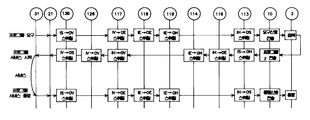
도 6은 유선 전화 서비스를 위한 신호 흐름도를 보여주는 것으로서, 유선 전화기(32)로부터 디지틀 전자 교환기 사이에 회선 채널에 실린 음성 데이터 혹은 신호가 ATM 셀로 맵핑되어 발신 신호, 교신성 음성 데이터의 송, 수신 및 통화 종료 요구 신호인 후크온(Hook on)신호가 각 ATM 단위 스위치들 (111, 117, 120, 129, 132, 135)를 통하여 셀 스위칭을 수행하므로서 가입자 액세스망으로서 유선 전화 서비스의 제공 과정을 나타내고 있다.Fig. 6 shows a signal flow diagram for wireline telephone service, in which voice data or signals carried on a circuit channel between a
도 3 및 도 6을 참조하면, 먼저, 유선 전화기(32)에서 망 종단 장치 NT(21)을 통하여 4x4 ATM 단위 스위치 소자0MN(135)의 입력단(IS)으로 ATM 셀로 맵핑된 발신 신호(P)가 입력된다. 그러면, 상기 4x4 ATM 단위 스위치 소자0MN(135)는 셀 스위칭을 통해 출력단(OV)으로 입력 신호를 출력하고, 4x4 ATM 단위 스위치 소자0M0(117)의 입력단(IV)으로 입력된 발신 신호(P)는 출력단(OH)으로 스위칭이 수행된다. 상기 발신 신호(P)는 4x4 ATM 단위 스위치 소자000(111)의 입력단(IH)으로 전달되고, 출력단(OV)으로 셀 스위칭이 수행되어 4x4 ATM 단위 스위치 소자001(120)의 입력단(IV)으로 전송되고, 상기 4x4 ATM 단위 스위치 소자001(120)에서 출력단(OS)으로 셀 스위칭이 수행된 후 디지틀 전자 교환기(3)로 전달된다.3 and 6, first, an outgoing signal P mapped to an ATM cell from the
그러면, 상기 디지틀 전자 교환기(3)에서는 상기 발신 신호(P)를 회선 채널(Circuit channel) 데이터로 변환하여 기존 회선 교환의 채널로 교환하고, 해당 응답 신호 혹은 상대방의 응답 데이터로 교환 출력한다. 이 때, 교신성의 상대방 음성 데이터가 ATM 셀로 맵핑된 데이터(Q)로서 4x4 ATM 단위 스위치 소자001(120)의 입력단(IS)으로 입력되면, 상기 4x4 ATM 단위 스위치 소자001(120)에서는 출력단(OV)으로 셀 스위칭이 수행되어 4x4 ATM 단위 스위치 소자00N(129)의 입력단(IV)으로 전송된다. 상기 4x4 ATM 단위 스위치 소자00N(129)은 출력단(OH)으로 셀 스위칭이 수행된 후에 4x4 ATM 단위 스위치 소자01N(132)으로 전송하고, 상기 4x4 ATM 단위 스위치 소자01N(132)의 입력단(IH)에서 출력단(OH)으로 셀 스위칭을 수행한 후, 4x4 ATM 단위 스위치 소자0MN(135)의 입력단(IH)으로 전송된다. 상기 4x4 ATM 단위 스위치 소자0MN(135)에서는 입력된 상기 셀 데이터(Q)가 출력단(OS)으로 셀 스위칭이 수행되어 망 종단 장치 NT (21)을 거쳐 유선 전화기(32)로 전달된다. 이 때, 상기 망 종단 장치(21)는 셀 데이터(Q)를 음성 데이터로 변환한다.Then, the digital
이와 같은 경로에 의해 유선 전화기(32)와 디지틀 전자 교환기(3) 사이에 음성 신호가 전달되며, 상기 유선 전화기(32)에서 유선 전화 서비스의 종료를 원하는 경우, 유선 전화기(32)를 후크온(Hook on)한다.A voice signal is transmitted between the
그러면, 상기 후크온(Hook on)에 해당하는 신호가 망 종단 장치 NT(21)에서 ATM 셀로 변환되어 4x4 ATM 단위 스위치 소자0MN(135)의 입력단(IS)으로 전송된다. 상기 4x4 ATM 단위 스위치 소자0MN(135)에서는 상기 후크온(Hook on) 신호가 출력단(OV)으로 셀 스위칭이 수행되어 4x4 ATM 단위 스위치 소자0M0(117)의 입력단(IV)으로 전송되고, 상기 4x4 ATM 단위 스위치 소자0M0(117)에서는 출력단(OH)으로 셀 스위칭이 수행되어 4x4 ATM 단위 스위치 소자000(111)의 입력단(IH)으로 전송된다. 그리고, 상기 4x4 ATM 단위 스위치 소자000(111)의 출력단(OV)으로 셀 스위칭이 수행되어 4x4 ATM 단위 스위치 소자001(120)의 입력단(IV)으로 전송되며, 상기 4x4 ATM 단위 스위치 소자001(120)의 입력단(IV)으로 전송된 ATM셀 즉, 후크온(Hook on)신호는 출력단(OS)으로 셀 스위칭이 수행되어 디지틀 전자 교환기(3)로 전송되므로서, 유선 전화 서비스가 최종 종료된다.Then, the signal corresponding to the hook (Hook on) is converted into an ATM cell in the network termination device NT (21) and transmitted to the input terminal (IS) of the 4x4 ATM unit
도 7은 본 발명의 일 실시예에 따른 무선망 서비스를 수용한 가입자 액세스망 구조도로서, 도 7을 참조하면, 무선망 서비스를 제공하기 위해 도 2에 도시된 것과 같은 3차원 링망에 무선 전화 서비스를 제공하는 마이크로셀 기지국(Microcell Base Station)(22), 피코셀 기지국(Picocell Base Station)(23) 및 이동 전화 교환기(4)가 각기 4x4 ATM 단위 스위치 소자(113, 130, 135)의 입력단(IS)과 출력단(OS)으로 연결되어 있다.FIG. 7 is a block diagram of a subscriber access network accommodating a wireless network service according to an embodiment of the present invention. Referring to FIG. 7, a wireless telephone service is provided in a three-dimensional ring network as shown in FIG. 2 to provide a wireless network service. Microcell Base Station (22), Picocell Base Station (23) and Mobile Switching Unit (4) providing 4x4 ATM
이 때, 상기 마이크로셀 기지국(Microcell Base Station)(22)은 이동 전화 단말기(34)와 통신을 하고, 상기 피코셀 기지국(Picocell Base Station)(23)은 이동 전화기(33)와 통신을 한다.At this time, the
도 8은 본 발명의 일 실시예에 따른 무선 전화 서비스 흐름도로서, 도 7 및 도 8을 참조하여 무선 전화 서비스 흐름을 설명하면 다음과 같다.8 is a flowchart of a wireless telephone service according to an embodiment of the present invention. Referring to FIGS. 7 and 8, the wireless telephone service flow will be described below.
먼저, 이동 전화기(33)에서 피코셀의 기지국(Picocell Base Station)(23)으로 고주파 변조 신호에서 디지틀 ATM 셀 신호로 변환된 발신 신호(A)를 4x4 ATM 단위 스위치 소자10N(130)의 입력단(IS)으로 입력되면, 상기 4x4 ATM 단위 스위치 소자10N(130)은 출력단(OH)으로 셀 스위칭하여 상기 발신 신호(A)를 4x4 ATM 단위 스위치 소자11N(133)의 입력단(IH)으로 입력한다. 상기 4x4 ATM 단위 스위치 소자11N(133)에서도 출력단(OH)으로 셀 스위칭이 수행되며, 상기 ATM 셀의 발신 신호(A)는 4x4 ATM 단위 스위치 소자1MN(136)의 입력단(IH)으로 입력되고 출력단(OE)으로 셀 스위칭이 수행되어 4x4 ATM 단위 스위치 소자LMN(137)의 입력단(IE)으로 전송된다. 상기 4x4 ATM 단위 스위치 소자LMN(137)에서는 출력단(OE)으로 셀 스위칭이 수행되며, 출력단(OE)으로 출력된 상기 발신 신호(A)는 4x4 ATM 단위 스위치 소자0MN(135)의 입력단(IE)으로 전송되어, 상기 4x4 ATM 단위 스위치 소자0MN(135)의 셀 스위칭에 의해 출력단(OS)으로 출력되고, 상기 경로를 통해 발신 신호(A)를 수신한 이동 전화 교환기(4)에서 신호의 교환이 이루어진다.First, an outgoing signal A converted from a high frequency modulated signal to a digital ATM cell signal from a
상기 이동 전화 교환기(4)에서 교환된 데이터(A)는 다시 4x4 ATM 단위 스위치 소자0MN(135)의 입력단(IS)으로 입력되고, 셀 스위칭에 의해 출력단(OV)을 통해 4x4 ATM 단위 스위치 소자0M0(117)의 입력단(IV)으로 전송된다. 상기 4x4 ATM 단위 스위치 소자0M0(117)은 상기 데이터(A)를 셀 스위칭에 의해 출력단(OE)을 거쳐 4x4 ATM 단위 스위치 소자1M0(118)의 입력단(IE)으로 전송하며, 상기 4x4 ATM 단위 스위치 소자1M0(118)은 출력단(OE)으로 셀 스위칭을 수행한 후, 상기 데이터(A)를 4x4 ATM 단위 스위치 소자LM0(119)의 입력단(IE)으로 전송한다. 상기 4x4 ATM 단위 스위치 소자LM0(119)은 출력단(OH)으로 셀 스위칭을 수행한 후, 4x4 ATM 단위 스위치 소자L00(113)의 입력단(IH)으로 전송하며, 상기 4x4 ATM 단위 스위치 소자L00(113)에서는 출력단(OS)으로 셀 스위칭이 수행되어 데이터(A)가 마이크로셀의 기지국(Microcell Base Station)(22)를 통하여 이동 전화 단말기(34)로 전송된다.The data A exchanged at the
결국 이동 전화 단말기(33)으로부터 발신된 데이터(A)는 피코셀 기지국(Picocell Base Station)(23), 4x4 ATM 단위 스위치 소자(130, 133, 136, 137, 135)를 거쳐 이동 전화 교환기(4)로 전달되며, 상기 이동 전화 교환기(4)에서 교환된 데이터(A)는 4x4 ATM 단위 스위치 소자(135, 117, 118, 119, 113)에서 각기 셀 스위칭이 수행되어 마이크로셀 기지국(Microcell Base Station)(22)를 거쳐 이동 전화 단말기(34)로 전달된다.Eventually, the data A transmitted from the
반면, 도 8에서 이동 전화 단말기(34)에서 발생한 응답 데이터(B)는 4x4 ATM 단위 스위치 소자L00(113)의 입력단(IS)으로 입력되어 출력단(OE)으로 셀 스위칭이 수행되고, 4x4 ATM 단위 스위치 소자000(111)의 입력단(IE)으로 전송되며, 출력단(OV)으로 셀 스위칭이 수행되어 4x4 ATM 단위 스위치 소자001(120)의 입력단(IV)으로 전송된다. 4x4 ATM 단위 스위치 소자001(120)은 셀 스위칭에 의해 출력단(OV)으로 응답 데이터(B)를 출력하여, 4x4 ATM 단위 스위치 소자00N(129)의 입력단(IV)으로 입력한다. 상기 4x4 ATM 단위 스위치 소자00N(129)은 상기 입력단(IV)을 출력단(OH)으로 셀 스위칭을 수행한 후, 상기 응답 데이터(B)를 4x4 ATM 단위 스위치 소자01N(132)의 입력단(IH)으로 전송한다. 4x4 ATM 단위 스위치 소자01N(132)은 출력단(OH)으로 셀 스위칭을 수행하여 4x4 ATM 단위 스위치 소자0MN(135)의 입력단(IH)으로 응답 데이터(B)를 전송하고, 상기 4x4 ATM 단위 스위치 소자0MN(135)는 출력단(OS)으로 셀 스위칭하여 상기 응답 데이터(B)를 이동 전화 교환기(4)로 전송한다. 상기 이동 전화 교환기(4)에서는 해당 프로세싱을 거쳐 상기 응답 데이터(B)를 교환하고, 교환된 응답 데이터(B)는 상기 4x4 ATM 단위 스위치 소자0MN(135)의 입력단(IS)으로 재 전송되고, 출력단(OH)으로 셀 스위칭이 수행되어 4x4 ATM 단위 스위치 소자00N(129)의 입력단(IH)으로 전송된다. 상기 4x4 ATM 단위 스위치 소자00N(129)에서는 입력단(IH)으로부터 출력단(OE)으로 셀 스위칭을 수행한 후에 4x4 ATM 단위 스위치 소자10N(130)의 입력단(IE)으로 전송하고, 상기 4x4 ATM 단위 스위치 소자10N(130)에서는 출력단(OS)으로 셀 스위칭이 수행된다. 상기 4x4 ATM 단위 스위치 소자10N(130)에서 셀 스위칭이 수행된 응답 데이터(B)는 피코셀 기지국(Picocell Base Station)(23)을 거쳐 이동 전화 단말기(33)로 전달된다.On the contrary, in FIG. 8, the response data B generated by the
결국 이동 전화 단말기(34)로부터 발신된 데이터(B)는 마이크로셀 기지국(Microcell Base Station)(22), 4x4 ATM 단위 스위치 소자(113, 111, 120, 129, 132, 135)와 이동 전화 교환기(4), 그리고 4x4 ATM 단위 스위치 소자 (135, 129, 130)에서 각기 셀 스위칭이 수행되어 피코셀 기지국(Picocell Base Station)(23)을 거쳐 이동 전화 단말기(33)로 전달되었다.Eventually, the data B transmitted from the
상기와 같이 본 발명의 3차원 링망을 구성하면 그 링망에 연결된 각종 서비스 제공자에 따라 유, 무선망 서비스를 모두 제공할 수 있다.When the three-dimensional ring network of the present invention is configured as described above, both wired and wireless network services can be provided according to various service providers connected to the ring network.
상기와 같은 본 발명은 3차원 링망에 연결된 서비스 제공자에 따라 전화, 인터넷, 주문형 비디오 서비스 및 디지틀 방송 서비스 등의 유선망 서비스와, 이동 전화 및 무선 데이터 서비스 등의 무선망 서비스를 모두 제공하는 통합 가입자 액세스망으로서 각기 서비스 형태별로 구축된 액세스망의 비용 부담이 없고, 단일 액세스망으로서 유지 보수가 용이하며, 방송과 통신 및 정보 서비스를 융합화할 수 있다. 또한, 저속부터 고속의 데이터를 서비스할 수 있으며, 실시간 및 비 실시간 데이터 서비스를 동시에 제공할 수 있으며, 대칭형 데이터 서비스와 비대칭형 데이터 서비스를 함께 제공할 수 있다는 장점이 있다.As described above, the present invention provides an integrated subscriber access that provides both wired network services such as telephone, Internet, on-demand video service, and digital broadcasting service, and wireless network services such as mobile phone and wireless data service according to a service provider connected to a 3D ring network. As a network, there is no cost burden of an access network built for each service type, and maintenance is easy as a single access network, and broadcasting, communication, and information services can be converged. In addition, there is an advantage that can provide low-speed to high-speed data, can provide real-time and non-real-time data services at the same time, can provide a symmetric data service and an asymmetric data service.
Claims (5)
Priority Applications (1)
| Application Number | Priority Date | Filing Date | Title |
|---|---|---|---|
| KR1019970033525A KR100248425B1 (en) | 1997-07-18 | 1997-07-18 | ATM switch network of 3D ring as subscriber access network for wired / wireless converged network |
Applications Claiming Priority (1)
| Application Number | Priority Date | Filing Date | Title |
|---|---|---|---|
| KR1019970033525A KR100248425B1 (en) | 1997-07-18 | 1997-07-18 | ATM switch network of 3D ring as subscriber access network for wired / wireless converged network |
Publications (2)
| Publication Number | Publication Date |
|---|---|
| KR19990010683A KR19990010683A (en) | 1999-02-18 |
| KR100248425B1 true KR100248425B1 (en) | 2000-03-15 |
Family
ID=19514934
Family Applications (1)
| Application Number | Title | Priority Date | Filing Date |
|---|---|---|---|
| KR1019970033525A Expired - Fee Related KR100248425B1 (en) | 1997-07-18 | 1997-07-18 | ATM switch network of 3D ring as subscriber access network for wired / wireless converged network |
Country Status (1)
| Country | Link |
|---|---|
| KR (1) | KR100248425B1 (en) |
Cited By (1)
| Publication number | Priority date | Publication date | Assignee | Title |
|---|---|---|---|---|
| US7986950B2 (en) | 2002-08-07 | 2011-07-26 | Interdigital Technology Corporation | Wideband code division multiple access user equipment for receiving multimedia broadcast/multicast service |
Families Citing this family (1)
| Publication number | Priority date | Publication date | Assignee | Title |
|---|---|---|---|---|
| KR100417850B1 (en) * | 2000-11-22 | 2004-02-05 | 에스케이 텔레콤주식회사 | Integration system of wireless network and the internet |
-
1997
- 1997-07-18 KR KR1019970033525A patent/KR100248425B1/en not_active Expired - Fee Related
Cited By (4)
| Publication number | Priority date | Publication date | Assignee | Title |
|---|---|---|---|---|
| US7986950B2 (en) | 2002-08-07 | 2011-07-26 | Interdigital Technology Corporation | Wideband code division multiple access user equipment for receiving multimedia broadcast/multicast service |
| US8417245B2 (en) | 2002-08-07 | 2013-04-09 | Intel Corporation | Method and wireless transmit/receive unit (WTRU) for receiving multimedia broadcast/multicast service |
| US9014710B2 (en) | 2002-08-07 | 2015-04-21 | Intel Corporation | Method and wireless transmit/receive unit (WTRU) for receiving multimedia broadcast/multicast service |
| US9756481B2 (en) | 2002-08-07 | 2017-09-05 | Intel Corporation | Method and wireless transmit/receive unit (WTRU) for receiving multimedia broadcast/multicast service |
Also Published As
| Publication number | Publication date |
|---|---|
| KR19990010683A (en) | 1999-02-18 |
Similar Documents
| Publication | Publication Date | Title |
|---|---|---|
| RU2163059C2 (en) | Method and device for extending communication network coverage range in communication system | |
| KR0143217B1 (en) | A mobile telephone network structure | |
| US5640196A (en) | Method and apparatus for facilitating two way oral communications utilizing a television cable system | |
| US5790173A (en) | Advanced intelligent network having digital entertainment terminal or the like interacting with integrated service control point | |
| US6738981B1 (en) | General access system | |
| US4518989A (en) | Buffer memory dispersion type video/audio transmission system with spatially and timewise divided inter-office junction lines | |
| JP3842294B2 (en) | System and method for handling video telephone calls | |
| JPH09153905A (en) | Multimedia distribution network containing video switchboard | |
| JPH0833029A (en) | Mobile station certifying system for private electronic exchange | |
| CA1147449A (en) | Combined wired broadcasting and viewphone system | |
| US8432900B2 (en) | Hybrid type telephony system | |
| JPH1155408A (en) | Telephone system transmitting advertising information | |
| KR100248425B1 (en) | ATM switch network of 3D ring as subscriber access network for wired / wireless converged network | |
| JPH10510685A (en) | Mobile station access for cordless terminal mobility | |
| JPH10107896A (en) | Connection of many low data rate telephone lines for bringing high data rate communication | |
| JP2959462B2 (en) | Communication channel setting method | |
| US20030128714A1 (en) | Multimedia communication system, multimedia communication method,and multimedia communication terminal | |
| KR20000030071A (en) | Receiv and sending device for radio communication | |
| JP2874608B2 (en) | Three-way calling between a videophone exchange and a videophone | |
| KR100265535B1 (en) | Interworking function | |
| KR100489862B1 (en) | Method and apparatus for law enforcement to easily monitor cellular telephone calls | |
| KR100200624B1 (en) | Apparatus of connecting telephone line of data communication signal | |
| RU8860U1 (en) | DIGITAL AUTOMATIC TELECOMMUNICATION SYSTEM FOR COMMUNICATING SUBSCRIBERS TO COMMON USE TELEPHONE COMPONENTS | |
| KR20010070612A (en) | Mobile Network using a Pico BTS apparatus and a method of controling such system | |
| JP2004048215A (en) | Internet phone system by mobile communication equipment |
Legal Events
| Date | Code | Title | Description |
|---|---|---|---|
| A201 | Request for examination | ||
| PA0109 | Patent application |
St.27 status event code: A-0-1-A10-A12-nap-PA0109 |
|
| PA0201 | Request for examination |
St.27 status event code: A-1-2-D10-D11-exm-PA0201 |
|
| R17-X000 | Change to representative recorded |
St.27 status event code: A-3-3-R10-R17-oth-X000 |
|
| R18-X000 | Changes to party contact information recorded |
St.27 status event code: A-3-3-R10-R18-oth-X000 |
|
| PG1501 | Laying open of application |
St.27 status event code: A-1-1-Q10-Q12-nap-PG1501 |
|
| E701 | Decision to grant or registration of patent right | ||
| PE0701 | Decision of registration |
St.27 status event code: A-1-2-D10-D22-exm-PE0701 |
|
| GRNT | Written decision to grant | ||
| PR0701 | Registration of establishment |
St.27 status event code: A-2-4-F10-F11-exm-PR0701 |
|
| PR1002 | Payment of registration fee |
Fee payment year number: 1 St.27 status event code: A-2-2-U10-U11-oth-PR1002 |
|
| PN2301 | Change of applicant |
St.27 status event code: A-5-5-R10-R11-asn-PN2301 St.27 status event code: A-5-5-R10-R13-asn-PN2301 |
|
| PG1601 | Publication of registration |
St.27 status event code: A-4-4-Q10-Q13-nap-PG1601 |
|
| PN2301 | Change of applicant |
St.27 status event code: A-5-5-R10-R11-asn-PN2301 St.27 status event code: A-5-5-R10-R13-asn-PN2301 |
|
| PN2301 | Change of applicant |
St.27 status event code: A-5-5-R10-R11-asn-PN2301 St.27 status event code: A-5-5-R10-R13-asn-PN2301 |
|
| PN2301 | Change of applicant |
St.27 status event code: A-5-5-R10-R11-asn-PN2301 St.27 status event code: A-5-5-R10-R13-asn-PN2301 |
|
| PR1001 | Payment of annual fee |
Fee payment year number: 4 St.27 status event code: A-4-4-U10-U11-oth-PR1001 |
|
| PR1001 | Payment of annual fee |
Fee payment year number: 5 St.27 status event code: A-4-4-U10-U11-oth-PR1001 |
|
| PR1001 | Payment of annual fee |
Fee payment year number: 6 St.27 status event code: A-4-4-U10-U11-oth-PR1001 |
|
| PR1001 | Payment of annual fee |
Fee payment year number: 7 St.27 status event code: A-4-4-U10-U11-oth-PR1001 |
|
| PR1001 | Payment of annual fee |
Fee payment year number: 8 St.27 status event code: A-4-4-U10-U11-oth-PR1001 |
|
| PR1001 | Payment of annual fee |
Fee payment year number: 9 St.27 status event code: A-4-4-U10-U11-oth-PR1001 |
|
| PR1001 | Payment of annual fee |
Fee payment year number: 10 St.27 status event code: A-4-4-U10-U11-oth-PR1001 |
|
| R18-X000 | Changes to party contact information recorded |
St.27 status event code: A-5-5-R10-R18-oth-X000 |
|
| PN2301 | Change of applicant |
St.27 status event code: A-5-5-R10-R11-asn-PN2301 St.27 status event code: A-5-5-R10-R13-asn-PN2301 |
|
| FPAY | Annual fee payment |
Payment date: 20091208 Year of fee payment: 11 |
|
| PR1001 | Payment of annual fee |
Fee payment year number: 11 St.27 status event code: A-4-4-U10-U11-oth-PR1001 |
|
| PN2301 | Change of applicant |
St.27 status event code: A-5-5-R10-R11-asn-PN2301 St.27 status event code: A-5-5-R10-R13-asn-PN2301 |
|
| LAPS | Lapse due to unpaid annual fee | ||
| PC1903 | Unpaid annual fee |
Not in force date: 20101218 Payment event data comment text: Termination Category : DEFAULT_OF_REGISTRATION_FEE St.27 status event code: A-4-4-U10-U13-oth-PC1903 |
|
| PC1903 | Unpaid annual fee |
Ip right cessation event data comment text: Termination Category : DEFAULT_OF_REGISTRATION_FEE Not in force date: 20101218 St.27 status event code: N-4-6-H10-H13-oth-PC1903 |
|
| R18-X000 | Changes to party contact information recorded |
St.27 status event code: A-5-5-R10-R18-oth-X000 |
|
| R18-X000 | Changes to party contact information recorded |
St.27 status event code: A-5-5-R10-R18-oth-X000 |
|
| R18-X000 | Changes to party contact information recorded |
St.27 status event code: A-5-5-R10-R18-oth-X000 |
|
| R18-X000 | Changes to party contact information recorded |
St.27 status event code: A-5-5-R10-R18-oth-X000 |
|
| R18-X000 | Changes to party contact information recorded |
St.27 status event code: A-5-5-R10-R18-oth-X000 |
|
| PN2301 | Change of applicant |
St.27 status event code: A-5-5-R10-R11-asn-PN2301 St.27 status event code: A-5-5-R10-R13-asn-PN2301 |
|
| P22-X000 | Classification modified |
St.27 status event code: A-4-4-P10-P22-nap-X000 |
|
| R18-X000 | Changes to party contact information recorded |
St.27 status event code: A-5-5-R10-R18-oth-X000 |
|
| R18-X000 | Changes to party contact information recorded |
St.27 status event code: A-5-5-R10-R18-oth-X000 |