KR100237872B1 - Wavelength Divider Coupling Device Using Fiber Optic Grating - Google Patents
Wavelength Divider Coupling Device Using Fiber Optic Grating Download PDFInfo
- Publication number
- KR100237872B1 KR100237872B1 KR1019970022706A KR19970022706A KR100237872B1 KR 100237872 B1 KR100237872 B1 KR 100237872B1 KR 1019970022706 A KR1019970022706 A KR 1019970022706A KR 19970022706 A KR19970022706 A KR 19970022706A KR 100237872 B1 KR100237872 B1 KR 100237872B1
- Authority
- KR
- South Korea
- Prior art keywords
- wavelength
- optical
- coupling device
- optical fiber
- branch coupling
- Prior art date
- Legal status (The legal status is an assumption and is not a legal conclusion. Google has not performed a legal analysis and makes no representation as to the accuracy of the status listed.)
- Expired - Lifetime
Links
Images


Classifications
-
- G—PHYSICS
- G02—OPTICS
- G02B—OPTICAL ELEMENTS, SYSTEMS OR APPARATUS
- G02B6/00—Light guides; Structural details of arrangements comprising light guides and other optical elements, e.g. couplings
- G02B6/24—Coupling light guides
- G02B6/26—Optical coupling means
- G02B6/28—Optical coupling means having data bus means, i.e. plural waveguides interconnected and providing an inherently bidirectional system by mixing and splitting signals
- G02B6/293—Optical coupling means having data bus means, i.e. plural waveguides interconnected and providing an inherently bidirectional system by mixing and splitting signals with wavelength selective means
- G02B6/29379—Optical coupling means having data bus means, i.e. plural waveguides interconnected and providing an inherently bidirectional system by mixing and splitting signals with wavelength selective means characterised by the function or use of the complete device
- G02B6/2938—Optical coupling means having data bus means, i.e. plural waveguides interconnected and providing an inherently bidirectional system by mixing and splitting signals with wavelength selective means characterised by the function or use of the complete device for multiplexing or demultiplexing, i.e. combining or separating wavelengths, e.g. 1xN, NxM
-
- G—PHYSICS
- G02—OPTICS
- G02B—OPTICAL ELEMENTS, SYSTEMS OR APPARATUS
- G02B6/00—Light guides; Structural details of arrangements comprising light guides and other optical elements, e.g. couplings
- G02B6/02—Optical fibres with cladding with or without a coating
- G02B6/02057—Optical fibres with cladding with or without a coating comprising gratings
-
- G—PHYSICS
- G02—OPTICS
- G02B—OPTICAL ELEMENTS, SYSTEMS OR APPARATUS
- G02B6/00—Light guides; Structural details of arrangements comprising light guides and other optical elements, e.g. couplings
- G02B6/24—Coupling light guides
- G02B6/26—Optical coupling means
- G02B6/28—Optical coupling means having data bus means, i.e. plural waveguides interconnected and providing an inherently bidirectional system by mixing and splitting signals
- G02B6/293—Optical coupling means having data bus means, i.e. plural waveguides interconnected and providing an inherently bidirectional system by mixing and splitting signals with wavelength selective means
- G02B6/29304—Optical coupling means having data bus means, i.e. plural waveguides interconnected and providing an inherently bidirectional system by mixing and splitting signals with wavelength selective means operating by diffraction, e.g. grating
- G02B6/29316—Light guides comprising a diffractive element, e.g. grating in or on the light guide such that diffracted light is confined in the light guide
- G02B6/29317—Light guides of the optical fibre type
- G02B6/29319—With a cascade of diffractive elements or of diffraction operations
- G02B6/2932—With a cascade of diffractive elements or of diffraction operations comprising a directional router, e.g. directional coupler, circulator
-
- H—ELECTRICITY
- H04—ELECTRIC COMMUNICATION TECHNIQUE
- H04J—MULTIPLEX COMMUNICATION
- H04J14/00—Optical multiplex systems
- H04J14/02—Wavelength-division multiplex systems
- H04J14/03—WDM arrangements
- H04J14/0307—Multiplexers; Demultiplexers
Landscapes
- Physics & Mathematics (AREA)
- General Physics & Mathematics (AREA)
- Optics & Photonics (AREA)
- Engineering & Computer Science (AREA)
- Computer Networks & Wireless Communication (AREA)
- Signal Processing (AREA)
- Optical Communication System (AREA)
Abstract
본 발명은 광섬유격자를 이용한 파장분기결합장치에 관한 것으로, 기존의 파장분기결합장치와 동등한 성능을 가지면서 상대적으로 저렴한 비용으로 구현할 수 있는 파장분기결합장치 구현 기술로써, 파장분할다중화 전송시스템의 전체적인 구현비용을 절감시키는 잇점이 있다.The present invention relates to a wavelength branch coupling device using an optical fiber grating, and has a performance equivalent to that of a conventional wavelength branch coupling device and can be implemented at a relatively low cost. This has the advantage of reducing implementation costs.
Description
본 발명은 광섬유격자를 이용한 파장분기결합장치에 관한 것으로, 기존의 파장분기결합장치와 동등한 성능을 가지면서 상대적으로 저렴한 비용으로 구현할 수 있는 파장분기결합장치 구현 기술이며, 이는 운용특성상 수동소자이기 때문에 별도의 조작이 요구되지 않으며, 파장분할다중화가 도입된 기간망(해저 광케이블망, 국가간망, 시외망, 국간망), 시내망 및 가입자망과 근거리 통신망(LAN), 도시 지역망(MAN), 광대역망(WAN)등의 시스템에 광범위하게 적용될 수 있고, 또한 선형, 환형망과 계층망(hierarchical)등의 구성이 가능하여 망의 광역화등에도 적용할 수 있는 기술이다.The present invention relates to a wavelength branch coupling device using an optical fiber grating, and has a performance equivalent to that of a conventional wavelength branch coupling device and is a technology for implementing a wavelength branch coupling device that can be implemented at a relatively low cost. No separate operation is required, and main network (submarine optical cable network, inter-national network, long-distance network, inter-national network), local network, subscriber network and local area network (LAN), urban area network (MAN), broadband network It can be widely applied to systems such as (WAN), and it is also a technology that can be applied to wide area of the network because the configuration of linear, annular network and hierarchical network is possible.
종래 방법의 분기결합장치는 광섬유격자와 이의 구성소자로 구성하는 방법과 어레이드 웨이브가드 그레이팅(Arrayed Waveguide Grating)으로 구현하는 방법등으로 크게 대별된다.Conventional branching apparatuses are roughly classified into a method consisting of an optical fiber grating and its components and a method implemented by an arrayed waveguide grating.
이 중 광섬유격자를 이용하는 방법에는 3dB 광결합기와, 두 개의 병렬 동일 브래그(Bragg)파장의 광섬유격자(각 단자의 UV trimming : 온도 변화에 따른 arm길이 조절)와, 3dB 광결합기로 구성하는 방법이 있는데, 이는 온도변화에 따른 암(arm)의 길이를 발생할 때마다 조절하여 주어야 하는 점 등 운영상의 가장 큰 단점(운용불가능)이 있다.Among them, a fiber optic lattice is composed of a 3dB optical coupler, two parallel Bragg wavelength optical fiber grids (UV trimming of each terminal: arm length adjustment according to temperature change), and a 3dB optical coupler. This is the biggest disadvantage in operation (inoperability), such as the need to adjust the length of the arm (arm) in accordance with the temperature change.
또한 광서큘레이터와, 광섬유격자와, 광서큘레이터로 구성되는 방법이 있는 바, 이는 제1도에 도시된 바와 같다.There is also a method consisting of an optical circulator, an optical fiber grating, and an optical circulator, as shown in FIG.
이의 동작을 간략하게 설명하면, 먼저 파장의 분기 과정은 전단 광서큘레이터(1)를 통과한 후, 단일모드 광섬유 케이블(a2)을 통해 광섬유 격자(2)로 입력된다.Briefly, the operation of the wavelength is first passed through the shear optical circulator 1, and then input to the optical fiber grating 2 through the single-mode optical fiber cable (a2).
광섬유 격자(2)로 입력된 광은 이 광섬유 격자(2)의 공명파장과 동일한 파장은 격자(2)를 통과하지 못하고 다시 반사되고, 나머지 파장은 광서큘레이터(3)를 거쳐 단일모드 광섬유 케이블(a4)을 통해 전송된다.Light input to the
이때, 상기에서 다시 반사된 일부 파장은 전단 광서큘레이터(1)를 거쳐 단일 모드 광섬유 케이블(a5)을 통해 분기된다.At this time, some of the wavelengths reflected back are branched through the single mode optical fiber cable a5 via the shear optical circulator 1.
한편, 파장의 결합 과정을 설명하면, 상기 분기 과정에서 분기된 파장과 동일한 파장성분을 가지는 신호가 별도의 광원을 통해 단일모드 광섬유 케이블(a6)에 인가되어 후단의 광서큘레이터(3)로 입력된다.On the other hand, in the description of the wavelength combining process, a signal having the same wavelength component as the wavelength branched in the branching process is applied to the single mode optical fiber cable a6 through a separate light source and input to the rear
이 파장은 단일모드 광섬유 케이블(a3)을 통해 광섬유 격자(2)로 입력되나 이 역시 격자(2)를 통과하지 못하고 다시 반사된다.This wavelength is input to the optical fiber grating 2 through the single mode optical fiber cable a3, but again does not pass through the
이 반사된 파장은 광서큘레이터(3)를 통해 단일모드 광섬유 케이블(a4)로 전송되는데, 이때는 상기 분기과정에서 통과된 파장과 함께 전송된다.This reflected wavelength is transmitted to the single mode optical fiber cable a4 through the
따라서 최종적으로 단일모드 광섬유 케이블(a4)을 통해 전송되는 파장은 최초 단일모드 광섬유 케이블(a1)에 입력되었던 파장성분과 동일한 모든 파장이 전송되며, 단지 하나의 파장에 있어서 파장에 실린 정보가 다르게 된다.Therefore, the wavelength transmitted through the single mode optical fiber cable a4 is transmitted to all wavelengths identical to the wavelength components input to the first single mode optical fiber cable a1, and the information carried on the wavelength differs in only one wavelength. .
이 파장이 결국 결합장치에 의해 상기 분기된 파장과 결합된 것이다.This wavelength is then combined with the branched wavelength by a coupling device.
그러나 상기와 같이 동작되는 파장분기결합장치는 동작이나 성능에 있어서 문제되는 사항은 없으나, 광서큘레이터가 파장분기결합장치 전체 비용의 90% 정도를 차지하기 때문에 장치의 운용은 용이한 잇점이 있으나, 아주 고가의 비용이 드는 단점이 있다.However, there is no problem in operation or performance of the wavelength branch coupling device operated as described above, but the operation of the device is easy because the optical circulator occupies about 90% of the total cost of the wavelength branch coupling device. The disadvantage is a very expensive cost.
본 발명은 상기에 기술한 바와 같은 종래 문제점을 해결하기 위해, 파장분기결합장치의 결합단 구성을 광서큘레이터 대신, 광서큘레이터의 약 17분의 1 가격에 해당되는 광결합기로 구성하므로써, 파장분기결합 장치 전체 비용을 절감시키는 것을 목적으로 한다.In order to solve the conventional problems as described above, the present invention consists of a coupling stage configuration of the wavelength branch coupling device instead of an optical circulator, so that the optical coupler corresponds to about one-17th the cost of the optical circulator. The purpose is to reduce the overall cost of the branch coupling device.
즉, 기존의 광서큘레이터-광섬유격자-광서큘레이터로 구성되는 파장분기결합장치의 결합단의 광서큘레이터 대신에, 광서큘레이터의 약 17분의 1 가격에 해당되는 광결합기를 사용하므로써, 장치 전체 비용의 약 43%의 개선효과 및 동일한 성능을 갖는 시스팀을 구현하는 것이다.That is, instead of the optical circulator of the coupling end of the wavelength branch coupling device composed of the existing optical circulator-optical lattice-optical circulator, by using an optical coupler equivalent to about 1/17 of the optical circulator, Implementing a system with about 43% improvement in the overall cost of the device and the same performance.
제1도는 종래의 파장분기결합 장치의 개략적인 블록도.1 is a schematic block diagram of a conventional wavelength branch coupling device.
제2도는 본 발명에 의한 파장분기결합 장치의 개략적인 블록도.Figure 2 is a schematic block diagram of a wavelength branch coupling device according to the present invention.
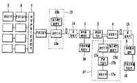
제3도는 본 발명에 의한 파장분기결합장치의 전송성능을 측정하기 위한 테스트 시스템의 구성 블록도.3 is a block diagram of a test system for measuring the transmission performance of the wavelength branch coupling device according to the present invention.
제4도는 본 발명에 의한 파장분기결합장치의 실시예를 나타내는 블럭도.4 is a block diagram showing an embodiment of a wavelength branch coupling device according to the present invention.
* 도면의 주요부분에 대한 부호의 설명* Explanation of symbols for main parts of the drawings
1 : 광서큘레이터 2 : 광섬유 격자1: optical circulator 2: optical fiber grating
4 : 광결합기 a1~a6 : 단일보드 광섬유 케이블4: optical coupler a1 ~ a6: single board optical fiber cable
5,11a : 광 송신기 6,11b,12,17b : 편광 조절기5,11a:
7 : 파장분할 다중 결합기 8,10,16 : 전송 오류율 측정기7
9 : 대역 통과 필터 11,13,17 : 외부 변조단9:
11c,13b,17a,17c : 광 변조기 11d,14,15 : 광 증폭기11c, 13b, 17a, 17c:
11e : 광 분배기 11f,13a,17d : 펄스 패턴 발생기11e:
상기와 같은 목적을 달성하기 위해 본 발명에서는 파장분할다중화 전송시스템의 파장분기결합장치에 있어서, 광서큘레이터와 광섬유격자를 통해 광을 분기시키고, 상기 광섬유 격자와 광결합기를 통해 광을 결합하는 구성을 갖는 것을 특징으로 한다.In order to achieve the above object, in the present invention, in the wavelength division multiplexing transmission system of the wavelength division multiplexing transmission system, the light is split through an optical circulator and an optical fiber grating, and the light is coupled to the optical grating and the optical coupler. Characterized in having a.
상술한 목적, 특징 및 장점은 첨부된 도면과 관련한 다음의 상세한 설명을 통하여 보다 분명해 질 것이다. 이하 첨부된 도면을 참조하여 본 발명의 실시예를 상세히 설명하며, 종래와 같은 구성은 동일 부호를 부여하여 설명한다.The above objects, features and advantages will become more apparent from the following detailed description taken in conjunction with the accompanying drawings. DETAILED DESCRIPTION Hereinafter, exemplary embodiments of the present invention will be described in detail with reference to the accompanying drawings.
제2도는 본 발명에 의해 구현된 파장분기결합장치의 구성 블록도로, 파장분기결합장치의 결합단에 광결합기(4)를 사용하여 두 포트중 한 포트에는 기존의 광서큘레이터를 사용하는 장치의 통과 채널이 갖는 삽입 손실과 대등한 수준의 삽입 손실을 갖게 하고, 다른 한 포트에는 결합된 채널의 전송 성능이 동일한 효과를 갖는 등 통과된 채널과 함께 파장분할 다중화되어 전송하게 된다.FIG. 2 is a block diagram showing the structure of a wavelength branch coupling device implemented according to the present invention, wherein the optical coupler 4 is used at the coupling end of the wavelength branch coupling device. The insertion loss has a level of insertion loss equivalent to that of the pass channel, and the transmission performance of the combined channel has the same effect on the other port.
제3도는 상기와 같은 구성된 파장분기결합장치의 성능을 테스트하여, 기존의 파장분기결합장치와 성능 비교를 해보기 위한 테스트 장치 블록도로, 광송신기(5)와 편광조절기(6)를 통해 파장이 입력되면 이는 파장분할다중결합기(7)를 거쳐 본 발명의 파장분기결합장치로 입력된다.3 is a block diagram of a test apparatus for testing the performance of the wavelength splitter coupling device configured as described above and comparing the performance with a conventional wavelength splitter coupling device. The wavelength is input through the
이때 파장분기결합장치의 첫째단인 광서큘레이터(1)를 통해 출력된 파장은 광섬유 격자(2)에서 반사된 일부 파장을 다시 입력받아 전송오류율 측정기(8)로 출력한다.At this time, the wavelength output through the optical circulator 1, which is the first stage of the wavelength branch coupling device, receives some wavelengths reflected from the
이 전송오류율 측정기(8)에서는 상기 분기된 파정을 검사하여 본 발명의 장치의 장치 성능을 측정한다.The transmission error
그리고 광결합기(4) 측으로는 외부변조단(11)을 통해 상기 분기된 파장과 동일성분을 가지는 파장이 생성되어 입력된다.On the optical coupler 4 side, a wavelength having the same component as the branched wavelength is generated and input through the
이때 상기 외부변조단(11)는 광송신기(11a)와, 편광조절기(11b), 그리고 분기된 파장과 동일성분의 파장을 생성하기 위해 사용하는 펄스패턴 발생기(11c)와, 상기 펄스패턴 발생기(11c)에서 출력되는 펄스에 따라 광을 변조시켜 출력하는 광변조기(11d)와, 상기 광변조기에서 출력된 광을 증폭하는 광증폭기(11e), 및 상기 광증폭기(11e)에서 출력된 파장을 분배하여 상기 파장분할다중결합기(7)와 광결합기(4)로 입력하는 광분배기(11f)로 이루어진다.In this case, the
이처럼 광결합기(4)를 통해 모든 파장이 결합된 출력광은 대역통과필터(9)를 통해 필터링 된 후, 전송오류율 측정기(10)에 입력되어 그 전송 정확도를 측정하게 된다.As such, the output light having all wavelengths combined through the optical coupler 4 is filtered through the
이상과 같은 실험을 통해 본 발명의 파장분기결합장치는 종래의 파장분기결합장치와 동일한 성능을 가지는 것을 알 수 있었다.Through the above experiments, it was found that the wavelength branch coupling device of the present invention has the same performance as the conventional wavelength branch coupling device.
제4도는 본 발명에 의해 구현된 파장분기결합장치를 실제 통신 시스템에서 사용할 수 있도록 한 일실시예로, 제2도의 단일모드 광섬유 케이블(a1)을 제4도의 광증폭기(14)에 연결하고, 또한 제2도의 단일모드 광섬유 케이블(a4)을 제4도의 광증폭기(15)에 연결한다.FIG. 4 is an embodiment in which the wavelength branch coupling device implemented by the present invention can be used in an actual communication system. The single mode optical fiber cable a1 of FIG. 2 is connected to the
그리고 광송신기(5)와 편광조절기(6)를 통해 입력된 다수의 광을 파장분할다중결합기(7)를 통해 하나로 묶어 편광 조절기(12)로 출력하고, 이 편광 조절기(12)를 통해 출력된 광은 외부변조단(13)을 거쳐 변조된 후 광증폭기(14)로 입력된다.Then, a plurality of light inputs through the
상기 광증폭기(14)에 입력된 파장은 상기 제3도에서 설명한 바와 같이 광서큘레이터(1)를 통해 분기된 파장의 전송 성능을 측정하고, 또 외부변조단(17)에서 생성된 상기 분기된 파장과 동일한 파장 신호를 입력받아 광결합시키는 광결합기(4)에서 출력된 광을 목표지점까지 전송한 후, 이의 전송 성능을 측정한다.The wavelength input to the
이상에서 상세히 설명한 바와 같이 본 발명은 기존 시스템 보다 저렴한 투자비에 유사 성능을 갖춘 파장분기결합장치를 제공하므로써, 파장분할다중화 전송시스템의 전체적인 구현 비용을 절감시키는 잇점이 있다.As described in detail above, the present invention has the advantage of reducing the overall implementation cost of the wavelength division multiplexing transmission system by providing a wavelength branch combining device having similar performance at a lower investment cost than the existing system.
아울러 본 발명의 바람직한 실시예들은 예시의 목적을 위해 개시된 것이며, 당업자라면 본 발명의 사상과 범위안에서 다양한 수정, 변경, 부가등이 가능할 것이며, 이러한 수정 변경 등은 이하의 특허 청구의 범위에 속하는 것으로 보아야 할 것이다.In addition, preferred embodiments of the present invention are disclosed for the purpose of illustration, those skilled in the art will be able to various modifications, changes, additions, etc. within the spirit and scope of the present invention, such modifications and modifications belong to the following claims You will have to look.
Claims (1)
Priority Applications (1)
| Application Number | Priority Date | Filing Date | Title |
|---|---|---|---|
| KR1019970022706A KR100237872B1 (en) | 1997-06-02 | 1997-06-02 | Wavelength Divider Coupling Device Using Fiber Optic Grating |
Applications Claiming Priority (1)
| Application Number | Priority Date | Filing Date | Title |
|---|---|---|---|
| KR1019970022706A KR100237872B1 (en) | 1997-06-02 | 1997-06-02 | Wavelength Divider Coupling Device Using Fiber Optic Grating |
Publications (2)
| Publication Number | Publication Date |
|---|---|
| KR19990000063A KR19990000063A (en) | 1999-01-15 |
| KR100237872B1 true KR100237872B1 (en) | 2000-01-15 |
Family
ID=19508347
Family Applications (1)
| Application Number | Title | Priority Date | Filing Date |
|---|---|---|---|
| KR1019970022706A Expired - Lifetime KR100237872B1 (en) | 1997-06-02 | 1997-06-02 | Wavelength Divider Coupling Device Using Fiber Optic Grating |
Country Status (1)
| Country | Link |
|---|---|
| KR (1) | KR100237872B1 (en) |
-
1997
- 1997-06-02 KR KR1019970022706A patent/KR100237872B1/en not_active Expired - Lifetime
Also Published As
| Publication number | Publication date |
|---|---|
| KR19990000063A (en) | 1999-01-15 |
Similar Documents
| Publication | Publication Date | Title |
|---|---|---|
| Johnson et al. | New design concept for a narrowband wavelength-selective optical tap and combiner | |
| JP3989627B2 (en) | Optical gate device, method of manufacturing the device, and system including the device | |
| CN103582808B (en) | optical line characteristic analysis device and analysis method thereof | |
| KR102039241B1 (en) | Method and system for differentiating macro-bend losses from splice and connector losses in fiber-optic link | |
| US5966236A (en) | Optical signal channel counter and optical amplification device using the same | |
| CA2259172A1 (en) | Optical transmitter | |
| JP2734778B2 (en) | Optical amplifier | |
| CN115452014A (en) | Optical frequency domain reflectometer with noise suppression and frequency division multiplexing of multi-reference-arm structure | |
| KR100501541B1 (en) | Apparatus for monitoring optical signal-to-noise ratio of the optical signal | |
| US20020005970A1 (en) | Dispersion compensator and method of compensating for dispersion | |
| US5852700A (en) | Method and device for the generation of ultrashort optical pulses | |
| KR0183945B1 (en) | Optical demultiplexer | |
| US6654104B2 (en) | Apparatus and method for measuring optical characteristics and recording medium | |
| KR100237872B1 (en) | Wavelength Divider Coupling Device Using Fiber Optic Grating | |
| US4790655A (en) | System for measuring laser spectrum | |
| JP2005091165A (en) | FBG sensing system | |
| JPH10107773A (en) | Optical wavelength division multiplex communication system | |
| CN208723907U (en) | A Fiber Phase Compensator Based on Mach-Zehnder Fiber Interferometer | |
| RU2521045C1 (en) | Method of setting up duplex links in one fibre using optical signals operating in opposite directions and having same carrier wavelength with retroreflection control | |
| JP2003514246A (en) | Method and apparatus for measuring polarization dispersion in optical fibers | |
| CN215222212U (en) | Quantum key distribution optical chip based on time phase coding | |
| US6771910B1 (en) | Optical bit interleaving | |
| JP2757816B2 (en) | Method for measuring characteristics of light intensity modulator and control method | |
| Katsuyama | In-service fiber line identification based on high-resolution fiber length measurement | |
| US20250110281A1 (en) | Device for transmitting data from solid core optical fibers to a hollow core fiber and method of use thereof |
Legal Events
| Date | Code | Title | Description |
|---|---|---|---|
| A201 | Request for examination | ||
| PA0109 | Patent application |
Patent event code: PA01091R01D Comment text: Patent Application Patent event date: 19970602 |
|
| PA0201 | Request for examination |
Patent event code: PA02012R01D Patent event date: 19970602 Comment text: Request for Examination of Application |
|
| PG1501 | Laying open of application | ||
| E701 | Decision to grant or registration of patent right | ||
| PE0701 | Decision of registration |
Patent event code: PE07011S01D Comment text: Decision to Grant Registration Patent event date: 19990831 |
|
| GRNT | Written decision to grant | ||
| PR0701 | Registration of establishment |
Comment text: Registration of Establishment Patent event date: 19991012 Patent event code: PR07011E01D |
|
| PR1002 | Payment of registration fee |
Payment date: 19991012 End annual number: 3 Start annual number: 1 |
|
| PG1601 | Publication of registration | ||
| PR1001 | Payment of annual fee |
Payment date: 20020927 Start annual number: 4 End annual number: 4 |
|
| PR1001 | Payment of annual fee |
Payment date: 20030930 Start annual number: 5 End annual number: 5 |
|
| PR1001 | Payment of annual fee |
Payment date: 20040930 Start annual number: 6 End annual number: 6 |
|
| PR1001 | Payment of annual fee |
Payment date: 20050930 Start annual number: 7 End annual number: 7 |
|
| PR1001 | Payment of annual fee |
Payment date: 20060912 Start annual number: 8 End annual number: 8 |
|
| PR1001 | Payment of annual fee |
Payment date: 20071008 Start annual number: 9 End annual number: 9 |
|
| PR1001 | Payment of annual fee |
Payment date: 20081006 Start annual number: 10 End annual number: 10 |
|
| PR1001 | Payment of annual fee |
Payment date: 20091006 Start annual number: 11 End annual number: 11 |
|
| PR1001 | Payment of annual fee |
Payment date: 20101006 Start annual number: 12 End annual number: 12 |
|
| PR1001 | Payment of annual fee |
Payment date: 20111004 Start annual number: 13 End annual number: 13 |
|
| FPAY | Annual fee payment |
Payment date: 20120928 Year of fee payment: 14 |
|
| PR1001 | Payment of annual fee |
Payment date: 20120928 Start annual number: 14 End annual number: 14 |
|
| FPAY | Annual fee payment |
Payment date: 20131004 Year of fee payment: 15 |
|
| PR1001 | Payment of annual fee |
Payment date: 20131004 Start annual number: 15 End annual number: 15 |
|
| FPAY | Annual fee payment |
Payment date: 20141006 Year of fee payment: 16 |
|
| PR1001 | Payment of annual fee |
Payment date: 20141006 Start annual number: 16 End annual number: 16 |
|
| FPAY | Annual fee payment |
Payment date: 20151006 Year of fee payment: 17 |
|
| PR1001 | Payment of annual fee |
Payment date: 20151006 Start annual number: 17 End annual number: 17 |
|
| FPAY | Annual fee payment |
Payment date: 20161005 Year of fee payment: 18 |
|
| PR1001 | Payment of annual fee |
Payment date: 20161005 Start annual number: 18 End annual number: 18 |
|
| EXPY | Expiration of term | ||
| PC1801 | Expiration of term |