JPWO2015105076A1 - Optical element, optical system, and imaging apparatus - Google Patents
Optical element, optical system, and imaging apparatus Download PDFInfo
- Publication number
- JPWO2015105076A1 JPWO2015105076A1 JP2015556793A JP2015556793A JPWO2015105076A1 JP WO2015105076 A1 JPWO2015105076 A1 JP WO2015105076A1 JP 2015556793 A JP2015556793 A JP 2015556793A JP 2015556793 A JP2015556793 A JP 2015556793A JP WO2015105076 A1 JPWO2015105076 A1 JP WO2015105076A1
- Authority
- JP
- Japan
- Prior art keywords
- optical element
- region
- transmittance
- light
- optical
- Prior art date
- Legal status (The legal status is an assumption and is not a legal conclusion. Google has not performed a legal analysis and makes no representation as to the accuracy of the status listed.)
- Pending
Links
Images


Classifications
-
- G—PHYSICS
- G02—OPTICS
- G02B—OPTICAL ELEMENTS, SYSTEMS OR APPARATUS
- G02B5/00—Optical elements other than lenses
- G02B5/005—Diaphragms
-
- G—PHYSICS
- G03—PHOTOGRAPHY; CINEMATOGRAPHY; ANALOGOUS TECHNIQUES USING WAVES OTHER THAN OPTICAL WAVES; ELECTROGRAPHY; HOLOGRAPHY
- G03B—APPARATUS OR ARRANGEMENTS FOR TAKING PHOTOGRAPHS OR FOR PROJECTING OR VIEWING THEM; APPARATUS OR ARRANGEMENTS EMPLOYING ANALOGOUS TECHNIQUES USING WAVES OTHER THAN OPTICAL WAVES; ACCESSORIES THEREFOR
- G03B11/00—Filters or other obturators specially adapted for photographic purposes
-
- G—PHYSICS
- G03—PHOTOGRAPHY; CINEMATOGRAPHY; ANALOGOUS TECHNIQUES USING WAVES OTHER THAN OPTICAL WAVES; ELECTROGRAPHY; HOLOGRAPHY
- G03B—APPARATUS OR ARRANGEMENTS FOR TAKING PHOTOGRAPHS OR FOR PROJECTING OR VIEWING THEM; APPARATUS OR ARRANGEMENTS EMPLOYING ANALOGOUS TECHNIQUES USING WAVES OTHER THAN OPTICAL WAVES; ACCESSORIES THEREFOR
- G03B9/00—Exposure-making shutters; Diaphragms
- G03B9/02—Diaphragms
Landscapes
- Physics & Mathematics (AREA)
- General Physics & Mathematics (AREA)
- Optics & Photonics (AREA)
- Optical Elements Other Than Lenses (AREA)
- Lenses (AREA)
Abstract
レンズユニットから分離して実装される場合であっても、シェーディング性能劣化を抑制しつつ、高い瞳内透過率と高い解像度とが得られる光学素子を提供する。光学素子は、光軸を中心に形成され、透過率が最も高い位置に対する相対的な透過率が95%以上の領域である中心領域と、前記中心領域の周囲に形成され、透過率が周辺に向かって減少する領域である中間領域と、前記中間領域の周囲に形成され、透過率が0.5%以下の領域である周辺領域とを有し、前記中心領域の直径をφ1、前記中間領域と前記周辺領域との境界の直径をφ2、前記光学系の絞り径をφaとした場合に、前記中心領域、前記中間領域および前記周辺領域が、1.1≦φ2/φa≦2.1と、少なくとも0.1≦φ1/φa≦1.1および0.0≦φ1/φ2≦0.95のいずれか一方とを満たすように形成されている。Provided is an optical element capable of obtaining high intra-pupil transmittance and high resolution while suppressing deterioration of shading performance even when mounted separately from a lens unit. The optical element is formed around the optical axis and is formed around the central region, which is a region having a relative transmittance of 95% or more with respect to a position where the transmittance is the highest, and the transmittance is around the periphery. An intermediate region that decreases toward the intermediate region, and a peripheral region that is formed around the intermediate region and has a transmittance of 0.5% or less. The diameter of the central region is φ1, and the intermediate region And the peripheral area are 1.1 ≦ φ2 / φa ≦ 2.1, where φ is the diameter of the boundary between the center region, the peripheral region, and φa, and the aperture diameter of the optical system is φa. And at least one of 0.1 ≦ φ1 / φa ≦ 1.1 and 0.0 ≦ φ1 / φ2 ≦ 0.95 is satisfied.
Description
本発明は、アポダイゼーション効果を奏する光学素子、それを用いた光学系および撮像装置に関する。 The present invention relates to an optical element that exhibits an apodization effect, an optical system using the optical element, and an imaging apparatus.
撮像装置等の光学機器において、レンズ等に入射する入射光の光量を調整するため、光学絞りや減光(ND:Neutral Density)フィルタ等が使用されている。例えば、携帯電話機や携帯端末などに搭載される撮像装置にも、光学絞りや減光フィルタが使用されている(例えば、特許文献1)。 In an optical apparatus such as an imaging apparatus, an optical diaphragm, a neutral density (ND) filter, or the like is used to adjust the amount of incident light incident on a lens or the like. For example, an optical aperture or a neutral density filter is also used in an imaging device mounted on a mobile phone or a mobile terminal (for example, Patent Document 1).
図17(a)〜(b)は、一般的な光学絞りの例を示す説明図である。なお、図17(a)は、一般的な光学絞りの一例である絞り910の上面図であり、図17(b)は、絞り910のA−A’線上における光の透過率分布の例を示す説明図である。図17(a)〜(b)に示すように、絞り910は、中心部分において光をほぼ100%透過させる開口部911と、その周辺部分において光をほぼ100%遮蔽する遮光部912とを備えている。このような絞り910は、例えば、遮光材料を用いて板状に形成されたものの中に開口部911を設けることにより形成される。
FIGS. 17A to 17B are explanatory views showing examples of a general optical diaphragm. FIG. 17A is a top view of a
携帯電話機や携帯端末に使用される撮像装置は高画素化が進む一方で、いぜんとして小型化や薄型化が望まれている。そのため、そのような光学機器に使われる光学絞りや減光フィルタ等も小型化や薄型化が望まれている。また近年、暗所での撮影感度を上げるために、F値の小さな明るいレンズを搭載した撮像モジュールも作られている。 Image pickup devices used for mobile phones and mobile terminals are increasingly required to be smaller and thinner while the number of pixels is increasing. Therefore, it is desired to reduce the size and thickness of optical diaphragms and neutral density filters used in such optical devices. In recent years, an imaging module equipped with a bright lens having a small F value has also been made in order to increase the sensitivity of photographing in a dark place.
しかし、一般的な光学絞りの場合、開口部の周囲において発生する光の回折による影響が無視できないほど大きくなり、解像度が劣化する問題があった。 However, in the case of a general optical diaphragm, there is a problem that the influence of the diffraction of light generated around the opening becomes so large that it cannot be ignored, and the resolution deteriorates.
解像度を劣化させない光学絞りとして、アポダイゼーション(apodization)効果を有するフィルタ(以下、アポダイズドフィルタと呼ぶ。)がある(特許文献2参照)。アポダイズドフィルタは、例えば入射光を光強度が正規分布となる光強度のビームに変換して出射することにより、投影面上での開口部の周辺で発生する回折の影響を低減できる。投影面上での回折による影響が無視できる範囲に抑えられれば、解像度を改善したり、被写界深度を深くできる。 As an optical aperture that does not deteriorate the resolution, there is a filter having an apodization effect (hereinafter referred to as an apodized filter) (see Patent Document 2). The apodized filter can reduce the influence of diffraction generated around the opening on the projection plane by, for example, converting incident light into a beam having a light intensity with a normal distribution of light intensity. If the influence of diffraction on the projection plane can be suppressed to a negligible range, the resolution can be improved and the depth of field can be increased.
図18(a)〜(b)は、アポダイズドフィルタの例を示す説明図である。図18(a)はアポダイズドフィルタの一例である絞り920の上面図であり、図18(b)は絞り920のB−B’線上における光の透過率分布の一例を示す説明図である。図18(a)〜(b)に示す絞り920は、光の透過率がほぼ0%の領域である周辺領域923と、中心部分の透過率をほぼ100%として、周辺領域923に向かって透過率が徐々に低下する領域である中間領域922とからなる。
FIGS. 18A to 18B are explanatory diagrams illustrating an example of an apodized filter. 18A is a top view of an
解像度の向上という点で、アポダイズドフィルタの透過率分布は正規分布となっているのが理想的である。しかし、透過率分布が正規分布となっている場合、光を遮光する部分が多くなるため、透過光量が大きく減少し、光学系が暗くなる問題があった。例えば、透過率分布が正規分布の場合、当該アポダイズドフィルタを垂直に透過する光束において、後段の光学系の絞り径内に入射する光の透過率(以下、瞳内透過率という。)は40%前後となる場合がある。 Ideally, the transmittance distribution of the apodized filter is a normal distribution in terms of improving the resolution. However, when the transmittance distribution is a normal distribution, there are many portions that block light, so that there is a problem that the amount of transmitted light is greatly reduced and the optical system becomes dark. For example, when the transmittance distribution is a normal distribution, the transmittance of light that enters the aperture diameter of the subsequent optical system (hereinafter referred to as intra-pupil transmittance) in a light beam that passes through the apodized filter vertically. It may be around 40%.
そこで、アポダイズドフィルタの中心領域における透過率を上げて、光の透過光量の減少を防ぐことが行われている(例えば、特許文献3の図3,図15参照)。図19(a)〜(b)は、透過率が略均一な中心領域921を設けたアポダイズドフィルタの例を示す説明図である。図19(a)は透過率が略均一な中心領域921を設けたアポダイズドフィルタの一例である絞り930の上面図であり、図19(b)は絞り930のC−C’線上における光の透過率分布の一例を示す説明図である。
Therefore, the transmittance in the central region of the apodized filter is increased to prevent a decrease in the amount of transmitted light (see, for example, FIGS. 3 and 15 of Patent Document 3). FIGS. 19A and 19B are explanatory diagrams illustrating an example of an apodized filter provided with a
また、本発明に関連する技術として、特許文献4には、撮像素子を有するイメージセンサの周囲に、フィルタ特性を有する蓋壁が備え付けられているフィルタ筐体を設け、イメージセンサとフィルタ筐体との間にレンズを配置した撮像装置の例が示されている。
In addition, as a technique related to the present invention,
しかし、図18(a)〜(b)や図19(a)〜(b)に示されるようなアポダイズドフィルタを、薄型の携帯電話機や携帯端末の撮像モジュールに用いようとした場合、次のような問題があった。第1に、スペース上の問題から実装が困難であった。例えば、ある既存のスマートフォンに用いられているレンズユニットにアポダイズドフィルタを新たに組み込もうとした場合、撮像モジュールの厚みを薄くするためには、アポダイズドフィルタは50μm〜80μm程度の厚さでなければならない。しかし、そのような素子厚で精度のよい透過率分布を有するアポダイズドフィルタを作製するのは難しく、厚みの制約から薄型のレンズユニットに利用するのは困難であった。第2に、薄型化のためにフィルムを用いて作製すると反りが生じる問題があった。第3に、レンズユニットに部品を追加すると重さが増し、駆動機構に負担がかかる問題があった。 However, when an apodized filter as shown in FIGS. 18A to 18B and FIGS. 19A to 19B is used for an imaging module of a thin mobile phone or a mobile terminal, There was a problem like this. First, it was difficult to mount due to space problems. For example, when an apodized filter is newly incorporated in a lens unit used in an existing smartphone, the apodized filter has a thickness of about 50 μm to 80 μm in order to reduce the thickness of the imaging module. Must be. However, it is difficult to produce an apodized filter having an accurate transmittance distribution with such an element thickness, and it is difficult to use it for a thin lens unit due to thickness restrictions. Secondly, there is a problem that warpage occurs when a film is used for thinning. Thirdly, adding parts to the lens unit increases the weight and places a burden on the drive mechanism.
以上のような問題は、アポダイズドフィルタをレンズユニットから分離して実装することにより回避できる。しかし、アポダイズドフィルタは光学絞りの機能も有しているため、アポダイズドフィルタをレンズユニットと分離して実装する場合には、アポダイズドフィルタと、レンズユニットに設置されている光学系のF値を決める光学絞りとの間に距離が生ずることに伴い、ケラレにより画面周辺の光量が低下する、すなわち、シェーディング(shading)が悪化するといった別の問題が発生する。 The above problems can be avoided by mounting the apodized filter separately from the lens unit. However, since the apodized filter also has an optical aperture function, when the apodized filter is mounted separately from the lens unit, the apodized filter and the optical system installed in the lens unit are used. As the distance between the optical aperture that determines the F value increases, another problem arises in that the amount of light around the screen decreases due to vignetting, that is, shading deteriorates.
なお、特許文献4には、レンズから離れた位置にフィルタ特性を有する蓋壁が備え付けられたフィルタ筐体を設けた撮像装置の例が示されているが、そのフィルタ特性がアポダイゼーション効果を奏するようなフィルタ特性である場合に、どのような透過率分布にすればよいかや、フィルタとレンズとの間の距離はどれくらい離すことができるか、といったことは何ら示されていない。アポダイズドフィルタをレンズユニットから分離して実装する場合、上述した回折の影響による解像度の低下や瞳内透過率の低下といった互いに関係しあう性能への影響を加味した上で、シェーディング対策をしなければならないが、特許文献4ではそのような影響については何ら考慮されていない。例えば、特許文献4には、フィルタ特性がアポダイゼーション効果を奏するようなフィルタ特性である場合に、ケラレによるシェーディング性能劣化を抑制しつつ、高い解像度と高い瞳内透過率とが得られるようなパラメータ条件等は何ら開示されていない。
Note that
そこで、本発明は、アポダイゼーション効果を奏する光学素子であって、レンズユニットから分離して実装される場合であっても、バランスの良い性能を光学系に付与できる光学素子の提供を目的とする。また、本発明は、実装が容易で、かつ性能バランスの良い光学系および撮像装置の提供を目的とする。 Therefore, an object of the present invention is to provide an optical element that exhibits an apodization effect and can provide a balanced performance to an optical system even when mounted separately from a lens unit. Another object of the present invention is to provide an optical system and an imaging apparatus that are easy to mount and have a good performance balance.
本発明による光学素子は、光学系にアポダイゼーション効果を奏する光学素子であって、光軸を中心に形成され、透過率が最も高い位置に対する相対的な透過率が95%以上の領域である中心領域と、前記中心領域の周囲に形成され、透過率が周辺に向かって減少する領域である中間領域と、前記中間領域の周囲に形成され、透過率が0.5%以下の領域である周辺領域とを有し、前記中心領域の直径をφ1、前記中間領域と前記周辺領域との境界の直径をφ2、前記光学系の絞り径をφaとした場合に、前記中心領域、前記中間領域および前記周辺領域が、以下の式(A)に加えて、以下の式(B)および式(C)の少なくとも一方を満たすように形成されていることを特徴とする。 An optical element according to the present invention is an optical element that exhibits an apodization effect in an optical system, and is formed around an optical axis, and is a central region having a relative transmittance of 95% or more with respect to a position having the highest transmittance. And an intermediate region which is formed around the central region and whose transmittance decreases toward the periphery, and a peripheral region which is formed around the intermediate region and has a transmittance of 0.5% or less When the diameter of the central region is φ1, the diameter of the boundary between the intermediate region and the peripheral region is φ2, and the aperture diameter of the optical system is φa, the central region, the intermediate region, and the The peripheral region is formed to satisfy at least one of the following formulas (B) and (C) in addition to the following formula (A).
1.1≦φ2/φa≦2.1 ・・・式(A)
0.1≦φ1/φa≦1.1 ・・・式(B)
0.0≦φ1/φ2≦0.95 ・・・式(C)1.1 ≦ φ2 / φa ≦ 2.1 Formula (A)
0.1 ≦ φ1 / φa ≦ 1.1 Formula (B)
0.0 ≦ φ1 / φ2 ≦ 0.95 (formula (C))
また、光学素子は、当該光学素子に垂直に入射する光束に対して、光軸を中心に直径が前記φaである領域内を透過する光の透過率が80%以上であってもよい。 Further, the optical element may have a transmittance of 80% or more for light transmitted through a region having a diameter of φa centered on the optical axis with respect to a light beam perpendicularly incident on the optical element.
また、光学素子は、当該光学素子を前記光学系に用いた場合に、当該光学素子を用いない場合の最大画角に相当する画面位置での光量を1としたときの前記画面位置での光量が0.75以上であってもよい。 In addition, when the optical element is used in the optical system, the optical element has a light quantity at the screen position when the light quantity at the screen position corresponding to the maximum angle of view when the optical element is not used is 1. May be 0.75 or more.
また、光学素子は、透明基板と、前記透明基板の表面に、光の一部または全部を吸収する材料により形成される光吸収部とを備え、少なくとも前記中間領域と前記周辺領域とには、前記光吸収部が形成されており、前記中間領域に形成されている光吸収部の厚みは、前記中心領域の側から周辺領域の側に向かって徐々に厚くなっていてもよい。 The optical element includes a transparent substrate, and a light absorbing portion formed of a material that absorbs part or all of light on the surface of the transparent substrate, and at least the intermediate region and the peripheral region include: The light absorbing portion may be formed, and the thickness of the light absorbing portion formed in the intermediate region may gradually increase from the central region side toward the peripheral region side.
また、前記周辺領域に形成されている光吸収部の厚みが、10μm以上かつ30μm以下であってもよい。 Moreover, the thickness of the light absorption part formed in the peripheral region may be not less than 10 μm and not more than 30 μm.
また、前記透明基板が、化学強化ガラスまたはサファイアを用いた基板であってもよい。 The transparent substrate may be a substrate using chemically tempered glass or sapphire.
また、光学素子は、組レンズを保護するために、撮像装置または機器の筐体に組み込まれる保護ガラスであり、前記光吸収部が形成されている面の反対側の透明基板の表面に、防汚コート層が形成されていてもよい。 The optical element is a protective glass incorporated in the housing of the imaging device or device in order to protect the assembled lens, and is provided on the surface of the transparent substrate opposite to the surface on which the light absorbing portion is formed. A dirty coating layer may be formed.
本発明による光学系は、上記のいずれかの光学素子と、組レンズとを備え、前記組レンズのうち前記光学素子の光出射側に最も近く配されているレンズの前記光学素子側表面と、前記光学素子の前記組レンズ側表面との間の距離の撮影時における最大値が、0.1mm以上かつ0.4mm未満であることを特徴とする。 An optical system according to the present invention includes any one of the optical elements described above and a combined lens, and the optical element side surface of the lens arranged closest to the light emitting side of the optical element among the combined lenses, The maximum value at the time of photographing of the distance between the optical element and the surface on the lens group side is 0.1 mm or more and less than 0.4 mm.
本発明による撮像装置は、組レンズと、前記組レンズを保護するために筐体に組み込まれている保護ガラスとを備え、前記保護ガラスは、透明基板と、前記透明基板の面上に形成されているアポダイゼーション層とを含み、前記アポダイゼーション層は、光軸を中心に形成され、透過率が最も高い位置に対する相対的な透過率が95%以上の領域である中心領域と、前記中心領域の周囲に形成され、透過率が周辺に向かって減少する領域である中間領域と、前記中間領域の周囲に形成され、透過率が0.5%以下の領域である周辺領域とを有し、前記保護ガラスの前記組レンズ側表面と、前記組レンズのうち前記保護ガラスに最も近く配されているレンズの前記保護ガラス側表面との間の距離の撮影時における最大値が、0.1mm以上かつ0.4mm未満であることを特徴とする。 An image pickup apparatus according to the present invention includes an assembled lens and a protective glass incorporated in a housing for protecting the assembled lens, and the protective glass is formed on a transparent substrate and the surface of the transparent substrate. An apodization layer, the apodization layer being formed around the optical axis and having a relative transmittance of 95% or more with respect to a position having the highest transmittance, and a periphery of the central region An intermediate region which is a region where the transmittance decreases toward the periphery, and a peripheral region which is formed around the intermediate region and has a transmittance of 0.5% or less, and the protection The maximum value at the time of photographing of the distance between the group lens side surface of glass and the protective glass side surface of the lens disposed closest to the protection glass among the group lenses is 0.1 mm or more and And less than .4Mm.
また、撮像装置は、前記保護ガラスが、透明基板と、前記透明基板の面上に形成されている前記アポダイゼーション層とを含んだ上記のいずれかの光学素子であってもよい。 In the imaging device, the protective glass may be any one of the above optical elements including a transparent substrate and the apodization layer formed on the surface of the transparent substrate.
また、撮像装置において、前記アポダイゼーション層は、前記保護ガラスの組レンズ側の面上に形成されていてもよい。 In the imaging device, the apodization layer may be formed on a surface of the protective glass on the side of the assembled lens.
本発明によれば、アポダイゼーション効果を奏する光学素子であって、レンズユニットから分離して実装される場合であっても、バランスの良い性能を光学系に付与できる光学素子を提供できる。例えば、レンズユニットから分離して実装される場合であっても、シェーディング性能劣化を抑制しつつ、高い瞳内透過率と高い解像度とが得られる光学素子を提供できる。 ADVANTAGE OF THE INVENTION According to this invention, it is an optical element which has an apodization effect, Comprising: Even if it is a case where it mounts separately from a lens unit, the optical element which can provide a balanced performance to an optical system can be provided. For example, even when mounted separately from the lens unit, it is possible to provide an optical element that can provide high intra-pupil transmittance and high resolution while suppressing deterioration of shading performance.
また、本発明によれば、実装が容易で、かつ性能バランスの良い光学系および撮像装置を提供できる。例えば、シェーディング性能劣化を抑制しつつ、実装容易性と瞳内透過率と解像度とを両立できる撮像装置を提供できる。 Further, according to the present invention, it is possible to provide an optical system and an imaging apparatus that are easy to mount and have a good performance balance. For example, it is possible to provide an imaging apparatus capable of achieving both mounting ease, intra-pupil transmittance, and resolution while suppressing shading performance deterioration.
以下、本発明の実施形態を図面を参照して説明する。 Hereinafter, embodiments of the present invention will be described with reference to the drawings.
実施形態1.
図1(a)〜(b)は、本発明の第1の実施形態の光学素子の例を示す説明図である。なお、図1(a)は第1の実施形態の光学素子の例である光学素子100の上面模式図であり、図1(b)は光学素子100のD−D’線上における光の透過率分布を示す説明図である。光学素子100は、いわゆるアポダイズドフィルタと呼ばれるものである。光学素子100は、図1(a)に示すように、光軸を中心に形成され、可視光(420nm以上、780nm以下)に対し、透過率がほぼ100%の領域である中心領域21と、中心領域21の周囲に形成され、透過率が周辺に向かって減少する領域である中間領域22と、中間領域22の周囲に形成され、透過率がほぼ0%の領域である周辺領域23とを有している。ここで透過率とは、透明基板の空気界面や、アポダイズドフィルタを構成する材料層間の界面における反射は無視しており、透明基板及び後述する光透過部を透過する光の透過率が100%になるよう定義する。
FIGS. 1A to 1B are explanatory views showing examples of the optical element according to the first embodiment of the present invention. 1A is a schematic top view of an
本実施形態において、中心領域21、中間領域22および周辺領域23は同心円状に、かつ連続した領域として形成されている。本実施形態では、最も高い透過率からの低下率が5%以内かそれよりも大きいかによって中心領域21と中間領域22とを区別する。一方、周辺領域23と中間領域22の区別は、透過率が0.5%以下かそれよりも大きいかによって行う。換言すると、光軸を中心に透過率が最も高い位置に対する相対的な透過率が95%以上の領域を中心領域21といい、透過率が0.5%以下の領域を周辺領域23といい、中心領域21と周辺領域23に挟まれた領域を中間領域22という。
In the present embodiment, the
中心領域21の透過率は必ずしも均一でなくてもよく、例えば、光軸が最も透過率が高く、周辺に向かって透過率が減少する分布であってもよい。また、周辺領域23の透過率は、0.5%以下であればよいが、0.1%以下がより好ましい。
The transmittance of the
なお、図1(b)に示すように、中間領域22と周辺領域23との境界において、透過率分布は連続していなくてもよい。例えば、中間領域22の周辺領域23側の端部における透過率は5〜20%であってもよい。
Note that, as illustrated in FIG. 1B, the transmittance distribution may not be continuous at the boundary between the
また、中心領域21の直径をφ1とし、アポダイズドフィルタとしての有効径すなわち中間領域22と周辺領域23との境界の直径をφ2とし、当該光学素子100の光出射側に配されるレンズユニット光学系のF値を決める光学的絞り径をφaとした場合に、光学素子100は、中心領域21、中間領域22および周辺領域23が、下記の式(1)と、下記の式(2)および式(3)の少なくとも一方とを満たすように形成されている。
Further, the diameter of the
1.1≦φ2/φa≦2.1 ・・・式(1) 1.1 ≦ φ2 / φa ≦ 2.1 (1)
0.1≦φ1/φa≦1.1 ・・・式(2) 0.1 ≦ φ1 / φa ≦ 1.1 Formula (2)
0.0≦φ1/φ2≦0.95 ・・・式(3) 0.0 ≦ φ1 / φ2 ≦ 0.95 (3)
上記の式(1)に加えて、式(2)または式(3)を満たすことによって、瞳内透過率を高く、かつ所定の空間周波数におけるMTF(Modulation Transfer Function)の値を高くできる。したがって、本実施形態の光学素子100をカメラ等の撮像装置に用いた場合に、よりよい画質の画像を撮像できる。また、本実施形態の光学素子100は、光学系のレンズから離れて配されてもよく、そのような場合であってもケラレによる画面周辺光量の低下を、許容範囲内に抑えることができる。以下、φ2/φaを有効径率といい、φ1/φ2をFT率という。
By satisfying the formula (2) or the formula (3) in addition to the above formula (1), the intra-pupil transmittance can be increased and the MTF (Modulation Transfer Function) value at a predetermined spatial frequency can be increased. Therefore, when the
一般にアポダイズドフィルタにおいて、瞳内透過率とMTFとはトレードオフの関係にある。既に説明したように、解像度の向上という点で、アポダイズドフィルタの透過率分布は正規分布となっているのが理想的であるが、その場合光を遮光する部分が多くなるため、透過光量が大きく減少し、光学系が暗くなる。例えば、透過率分布が正規分布のアポダイズドフィルタの場合、該アポダイズドフィルタのうち光学系の絞り径φa内に相当する領域を垂直に入射する光の瞳内透過率は40%前後となる。瞳内透過率を大きくしようと光学系の絞り径φaに占める中心領域21を大きくすると、中間領域22の幅が小さくなるために、MTFの値が減少する。
In general, in an apodized filter, intra-pupil transmittance and MTF are in a trade-off relationship. As described above, it is ideal that the transmittance distribution of the apodized filter is a normal distribution in terms of improving the resolution, but in this case, the portion that blocks light increases, so the amount of transmitted light Is greatly reduced and the optical system becomes dark. For example, in the case of an apodized filter with a normal transmittance distribution, the transmittance in the pupil of light perpendicularly incident on a region corresponding to the aperture diameter φa of the optical system of the apodized filter is about 40%. Become. When the
結像光学系においては、通常の光学絞りに相当する円形開口を通過した光は回折により、結像面における点像分布は同心円状の明暗のパターンになる。光軸中心にエアリーディスクと呼ばれる明るい円形領域があり、その周囲にエアリーパターンと呼ばれる同心円環の回折パターンを生じる。この回折により生じるエアリーパターンの強度は、主に空間周波数の低周波数における解像度、コントラストに影響を与えるため、エアリーパターン特にエアリーディスク近傍の第1明環の強度が抑えられているのが良いとされている。アポダイゼーション効果を利用すると、エアリーパターンの強度を低下できる。エアリーパターンの強度は、比較的低い空間周波数の重なりの影響を受けやすいことから、本実施形態ではMTF50本/mmやMTF100本/mmの値を見ることにより解像度の善し悪しを判断する。また、撮像光学系においては、画面中心と周辺で解像度のバランスがとれるよう設計されるが、画面周辺の像を形成する光線は光軸から外れた斜入射光線であり、一般の撮像装置では、光学系の収差により画面中心に比べ画面周辺の解像度を高くすることは設計上困難であり、アポダイズドフィルタにより画面周辺の解像度が改善されることは好ましい。また、画面中心の解像度は既に十分な性能を有していることから、本実施形態では、画面中心の解像度よりも画面周辺の解像度を重視する。画面周辺の像を形成する光線は光軸から外れた斜入射光線であり、一般の撮像装置では、光学系の収差により画面中心に比べ解像度が劣る。アポダイズドフィルタの解像度改善効果は、このような斜入射光線の収差による解像度劣化を改善する働きも期待できる。 In the imaging optical system, light passing through a circular aperture corresponding to a normal optical aperture is diffracted, and the point image distribution on the imaging surface becomes a concentric bright and dark pattern. There is a bright circular area called an Airy disk in the center of the optical axis, and a concentric ring diffraction pattern called an Airy pattern is generated around the area. Since the intensity of the Airy pattern generated by this diffraction mainly affects the resolution and contrast at low spatial frequencies, the intensity of the Airy pattern, particularly the first bright ring near the Airy disk, should be suppressed. ing. If the apodization effect is used, the strength of the Airy pattern can be reduced. Since the intensity of the Airy pattern is easily affected by the overlap of relatively low spatial frequencies, in this embodiment, whether the resolution is good or bad is determined by looking at the values of 50 MTF / mm and 100 MTF / mm. The imaging optical system is designed so that the resolution is balanced at the center and the periphery of the screen, but the light beam forming the image around the screen is an oblique incident light beam that is off the optical axis. It is difficult in design to increase the resolution around the screen compared to the center of the screen due to aberration of the optical system, and it is preferable that the resolution around the screen is improved by the apodized filter. In addition, since the resolution at the center of the screen already has sufficient performance, in this embodiment, the resolution around the screen is more important than the resolution at the center of the screen. The light rays that form the image around the screen are obliquely incident light rays that deviate from the optical axis, and in general imaging devices, the resolution is inferior to the center of the screen due to aberrations of the optical system. The resolution improvement effect of the apodized filter can also be expected to improve the resolution degradation due to the aberration of the oblique incident light.
さらに、本実施形態では、素子面内の透過率分布を設計する際の指標(以下、設計指標)として、上述した瞳内透過率とMTFに加えて、画面周辺光量を用いる。 Furthermore, in the present embodiment, in addition to the above-described intra-pupil transmittance and MTF, a screen peripheral light amount is used as an index (hereinafter referred to as a design index) when designing the transmittance distribution in the element plane.
図2は、一般的なアポダイズドフィルタを用いた場合の画面周辺光量の例を示すグラフである。なお、図2は、図18(a)〜(b)に示すような正規分布の透過率分布を有するアポダイズドフィルタを用いた場合の例を示すグラフである。図2において、縦軸は画面中心すなわちField angle=0の光強度を1として規格化した光強度を示し、横軸は画面位置をその位置に入射する主光線の入射角で示している。また、図2では、アポダイズドフィルタと後段の光学系の第1レンズ間の距離Lに応じて、系列を分けて表示している。 FIG. 2 is a graph showing an example of the amount of light around the screen when a general apodized filter is used. FIG. 2 is a graph showing an example in which an apodized filter having a normal transmittance distribution as shown in FIGS. 18A to 18B is used. In FIG. 2, the vertical axis indicates the light intensity normalized with the light intensity at the center of the screen, ie, Field angle = 0, being 1, and the horizontal axis indicates the screen position as the incident angle of the principal ray incident on that position. In FIG. 2, the series is divided and displayed according to the distance L between the apodized filter and the first lens of the subsequent optical system.
図2の光学系は第1レンズに光学絞りが備えられているので、図2に示すように、距離Lが大きくなると、ケラレによる画面周辺光量の低下も大きくなる。また、その低下量は、画面周辺にいくほど大きくなる。 In the optical system of FIG. 2, since the first lens is provided with an optical aperture, as shown in FIG. 2, the decrease in the amount of light around the screen due to vignetting increases as the distance L increases. Further, the amount of decrease increases as the distance to the periphery of the screen increases.
このようなケラレによる画面周辺光量の低下を防止するため、本発明では式(1)に示すように、中間領域22と周辺領域23との境界の直径φ2を、光学系の絞り径φaを超える範囲にまで大きくする。
In order to prevent such a decrease in the amount of light around the screen due to vignetting, in the present invention, the diameter φ2 of the boundary between the
アポダイズドフィルタを設置することにより生じる画面周辺光量の低下具合を判断する指標として、以下のような規格化された画面周辺光量を考える。すなわち、ある決まった画面周辺位置におけるアポダイズドフィルタを設けない場合の光量を1として、アポダイズドフィルタを設置した場合の同位置における画面周辺の光量を規格化したものである。以下、このようなアポダイズドフィルタを設けない場合の同位置における光量を1として規格化された画面周辺光量を、第1規格化周辺光量と定義する。 The following standardized screen peripheral light quantity is considered as an index for judging the degree of reduction of the screen peripheral light quantity caused by installing the apodized filter. That is, the light amount when the apodized filter is not provided at a certain screen peripheral position is set to 1, and the light amount around the screen at the same position when the apodized filter is installed is standardized. Hereinafter, the screen peripheral light amount normalized with the light amount at the same position when the apodized filter is not provided as 1 is defined as a first normalized peripheral light amount.
多くの撮像モジュールでは、画面周辺の光量低下を補うための画像処理による補正が行われている。このため、アポダイズドフィルタを加えた時の光量の低下量が小さければ、画像処理による補正でまかなえることが多い。すなわち、たとえ画面中心の光量に対して画面周辺の光量が小さくても、第1規格化周辺光量が所定の値以上であれば、画像処理による補正を伴うことにより、シェーディング性能劣化は抑えられているとみなせる。以下、第1規格化周辺光量と区別するために、画面中心の光量を1とした場合の画面周辺の光量を第2規格化周辺光量という場合がある。 In many imaging modules, correction by image processing is performed to compensate for a decrease in the amount of light around the screen. For this reason, if the amount of decrease in the amount of light when an apodized filter is added is small, correction by image processing is often sufficient. In other words, even if the amount of light around the screen is smaller than the amount of light at the center of the screen, if the first normalized peripheral light amount is greater than or equal to a predetermined value, the shading performance deterioration is suppressed by accompanying correction by image processing. It can be regarded as being. Hereinafter, in order to distinguish from the first normalized peripheral light amount, the light amount around the screen when the light amount at the center of the screen is 1 may be referred to as the second normalized peripheral light amount.
以上を踏まえて、瞳内透過率とMTFと画面周辺光量という3つの性能に関する指標が各々所定の条件を満たすように、φaに対するφ1およびφ2の組合せを求める。なお、以下では、中心領域21のほとんどの部分の透過率が100%である場合について検討した。
Based on the above, a combination of φ1 and φ2 with respect to φa is obtained so that the three performance indicators of intra-pupil transmittance, MTF, and screen peripheral light amount satisfy predetermined conditions. In the following, the case where the transmittance of most part of the
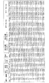
図3(a)および図3(b)は、光学素子100の設定パラメータに応じた瞳内透過率とMTFとの関係を示すグラフである。図3(a)において、横軸は瞳内透過率を示し、縦軸は光が38.5度で入射した場合のMTF100本/mmの値を示している。また、図3(b)において、横軸は瞳内透過率を示し、縦軸は光が38.5度で入射した場合のMTF50本/mmの値を示している。また、図3(a)および図3(b)に示される性能は、光学素子100と後段の光学系の第1レンズ間の距離Lを0.3mm、光学系のレンズの絞り径φaが1.64mmであり、焦点距離3.51mm、F値2.16として計算したものである。また、本例の光学系では最大画角である38.5度において、MTFを評価したが、異なる光学系の場合には、その最大画角付近の画角におけるMTFを評価すればよい。また、写真の画質を評価する場合などには、最大画角に対応する周辺領域の画質よりも少し中心に近い周辺領域の画質を重視したい場合も考えられる。そのような場合には、最大画角よりも小さい所定の画角(例えば、30度)におけるMTFを評価してもよい。
FIGS. 3A and 3B are graphs showing the relationship between the intra-pupil transmittance and the MTF according to the setting parameters of the
また、図3(a)および図3(b)では、有効径率に応じて系列を分けて示している。また、図中の曲線F101は、各系列内におけるFT率の変化の方向を示している。なお、有効径率=1の系列は比較例であり、光学系の絞り径φaとアポダイズドフィルタの有効径(直径)φ2とが一致しているアポダイズドフィルタである。なお、各マーカにおける具体的な設定パラメータの組合せの一部が、図20A〜図20Gに示されている。 Moreover, in FIG. 3A and FIG. 3B, the series is divided according to the effective diameter ratio. A curve F101 in the figure indicates the direction of change in the FT rate within each series. The series of effective diameter ratio = 1 is a comparative example, and is an apodized filter in which the aperture diameter φa of the optical system and the effective diameter (diameter) φ2 of the apodized filter coincide. A part of specific combinations of setting parameters in each marker is shown in FIGS. 20A to 20G.
図3(a)および図3(b)に示されるように、有効径率が同じ組合せの場合、FT率を低くするとMTFは高くなるが瞳内透過率は低くなり、FT率を高くすると瞳内透過率は高くなるがMTFは低くなることがわかる。また、FT率がある値を超えると急激にMTFが低くなることもわかる。 As shown in FIGS. 3 (a) and 3 (b), when the effective diameter ratio is the same combination, when the FT ratio is lowered, the MTF is increased but the intra-pupil transmittance is lowered, and when the FT ratio is increased, the pupil is increased. It can be seen that the internal transmittance increases but the MTF decreases. It can also be seen that when the FT rate exceeds a certain value, the MTF rapidly decreases.
したがって、例えば、瞳内透過率を0.80以上、かつ38.5度入射時のMTF100本/mmの値を0.54以上とする場合には、図3(a)のグラフ上の当該範囲に含まれる組合せにすればよい。また、例えば、瞳内透過率を0.80以上、かつ38.5度入射時のMTF50本/mmの値を0.74以上とする場合には、図3(b)のグラフ上の当該範囲に含まれる組合せにすればよい。 Therefore, for example, when the transmittance in the pupil is 0.80 or more and the value of MTF100 / mm at the incidence of 38.5 degrees is 0.54 or more, the corresponding range on the graph of FIG. May be included in the combination. Further, for example, when the transmittance in the pupil is 0.80 or more and the value of 50 MTF / mm at the incidence of 38.5 degrees is 0.74 or more, the corresponding range on the graph of FIG. May be included in the combination.
図4(a)および図4(b)は、光学素子100の設定パラメータに応じた瞳内透過率と画面周辺光量との関係を示すグラフである。図4(a)において、横軸は瞳内透過率を示し、縦軸は入射角38.5度に相当する位置における第1規格化周辺光量すなわちアポダイズドフィルタなし時の画面周辺光量を1とした場合の画面周辺光量を示している。また、図4(b)において、横軸は入射角38.5度に相当する位置における第2規格化周辺光量すなわち画面中心の光量を1とした場合の画面周辺光量を示し、縦軸は光が38.5度で入射した場合のMTF100本/mmの値を示している。また、図4(a)および図4(b)に示される性能の計算に用いた距離L、絞り径φa、焦点距離およびF値は、図3(a)〜(b)の場合と同様である。
4A and 4B are graphs showing the relationship between the intra-pupil transmittance and the screen peripheral light amount according to the setting parameters of the
図4(a)および図4(b)においても、有効径率に応じて系列を分けて示している。また、図中の曲線F101およびF102は、系列内におけるFT率の変化の方向を示している。なお、各マーカにおける具体的な設定パラメータの組合せの一部が、図20A〜図20Gに示されている。 In FIG. 4A and FIG. 4B as well, the series is shown separately according to the effective diameter ratio. Curves F101 and F102 in the figure indicate the direction of change in the FT rate within the series. A part of specific combinations of setting parameters in each marker is shown in FIGS. 20A to 20G.
図4(a)に示されるように、画面周辺光量は有効径率が大きいほど高くなり、同じ有効径率であれば、FT率には大きく依存しない。一方、瞳内透過率はFT率が大きいほど高くなるので、瞳内透過率を高くかつ画面周辺光量を高くするためには、有効径率を大きく、FT率を大きくすればよい。 As shown in FIG. 4A, the amount of light at the periphery of the screen increases as the effective diameter ratio increases, and if the effective diameter ratio is the same, it does not greatly depend on the FT ratio. On the other hand, the intra-pupil transmittance increases as the FT rate increases. Therefore, in order to increase the intra-pupil transmittance and the screen peripheral light amount, the effective diameter rate may be increased and the FT rate may be increased.
また、図4(b)に示されるように、MTFはFT率が低いほど良くなる。一方、画面周辺光量は有効径率が大きいほど高くなり、FT率の変化に対しては極小値をとる。したがって、画面周辺光量を高くかつMTFを良くするためには、有効径率を大きく、FT率を小さくすればよい。 Further, as shown in FIG. 4B, the MTF becomes better as the FT rate is lower. On the other hand, the screen peripheral light amount increases as the effective diameter ratio increases, and takes a minimum value with respect to the change in the FT ratio. Therefore, in order to increase the screen peripheral light amount and improve the MTF, the effective diameter ratio may be increased and the FT ratio may be decreased.
したがって、例えば、瞳内透過率を0.80以上、かつ第1規格化周辺光量を0.75以上とする場合には、有効径率を1.2以上として、図4(a)のグラフ上の当該範囲に含まれるようなFT率にすればよい。なお、図4(b)に示されるように、FT率を高くするとMTF値は減少する傾向にあるとともに、画面周辺光量は一旦減少した後に増加する傾向にあるため、瞳内透過率が許容範囲に収まる程度にFT率を小さくしてMTF値と画面周辺光量を優先させたり、MTF値が許容範囲に収まる程度にFT率を大きくして瞳内透過率と画面周辺光量の向上を優先させることも考えられる。 Therefore, for example, when the intra-pupil transmittance is 0.80 or more and the first normalized peripheral light amount is 0.75 or more, the effective diameter ratio is set to 1.2 or more on the graph of FIG. The FT rate may be set to be included in the range. As shown in FIG. 4B, when the FT ratio is increased, the MTF value tends to decrease, and the amount of light around the screen tends to increase after decreasing once. Reduce the FT rate to the extent that it falls within the range and give priority to the MTF value and the amount of light around the screen, or increase the FT rate to the extent that the MTF value falls within the permissible range and prioritize the improvement in the pupil transmittance and the amount of light around the screen Is also possible.
図5(a)は、設計パラメータの組合せにおける有効径率とφ1/φaとの関係を、性能に対する評価結果とともに示すグラフである。また、図5(b)は、設計パラメータの組合せにおける有効径率とFT率との関係を、性能に対する評価結果とともに示すグラフである。図5(a)および図5(b)のグラフは、設計パラメータの検討に用いたモデルデータのうち、瞳内透過率が0.80以上、かつ第1規格化周辺光量が0.75以上、かつ30度入射時のMTF50本/mmの値が0.86以上、かつ30度入射時のMTF100本/mmの値が0.725以上であるモデルデータをGoodモデルとして、各モデルデータにおける有効径率とφ1/φaとの関係および有効径率とFT率との関係をプロットしたものである。なお、本例では、最大画角ではなく最大画角よりも小さい画角におけるMTFを評価に用いている。図5(a)より、本例の組み合わせでは、有効径率が1.1〜2.1かつφ1/φaが0.1〜1.1の範囲にGoodモデルが含まれることがわかる。なお、図5(b)に示されるように、上記範囲は、有効径率とFT率とを用いて表現した場合、有効径率が1.1〜2.1かつFT率が0.0〜0.95の範囲と言うことができる。なお、各指標についての上記判定用しきい値はあくまで一例であって、これらに限定されない。例えば、瞳内透過率を0.80から0.85に変更すると、Goodモデルが含まれる範囲は、有効径率が1.1〜1.5かつφ1/φaが0.6〜1.1の範囲に変わる。
FIG. 5A is a graph showing the relationship between the effective diameter ratio and φ1 / φa in the combination of design parameters, together with the evaluation results for performance. FIG. 5B is a graph showing the relationship between the effective diameter ratio and the FT ratio in the combination of the design parameters together with the evaluation result for the performance. The graphs of FIGS. 5A and 5B show that, among the model data used for studying the design parameters, the intra-pupil transmittance is 0.80 or more and the first normalized peripheral light amount is 0.75 or more. In addition, model data in which the value of
また、図20A〜図20Gに示される各モデルデータは、中間領域22における透過率分布がガウス関数に従う分布であるとして各種性能を計算しているが、中間領域22における透過率分布はガウス関数に従う分布に限られない。例えば、コサインのn乗(例えば、2乗)に比例する関数に従う分布や、exp(x4)に従う分布や、偶数次ベキ乗の関数xnに従う関数であってもよい。ここで、xとは素子面内における中心、すなわち光軸位置からの距離である。20A to 20G calculate various performances assuming that the transmittance distribution in the
図6は、本実施形態の光学素子100の構成例を示す説明図である。図6に示すように、本実施形態の光学素子100は、透明な樹脂材料またはガラス等により形成された透明基板10、透明基板10の上に形成された可視光を吸収する材料により形成された光吸収部20および可視光を透過する材料により形成された光透過部30を有している。以下、光吸収部20と光透過部30とが形成されている層を、アポダイゼーション効果を生じさせる層という意味でアポダイゼーション層40と呼ぶ場合がある。
FIG. 6 is an explanatory diagram showing a configuration example of the
光吸収部20は、中心領域21においては殆ど形成されておらず、周辺領域23において厚く形成されており、中心領域21と周辺領域23との間の中間領域22においては、中心領域21の側から周辺領域23の側に向かって、徐々に厚さが厚くなるように形成されている。
The
ここで光吸収部20を構成する光吸収材料の光学濃度をODとし、光吸収部20の厚みをtとすると、透過率T(%)は、下記の(4)に示す式で表わされる。
Here, when the optical density of the light absorbing material constituting the
T=100×10(−OD×t) % ・・・(4)T = 100 × 10 (−OD × t) % (4)
また、光学濃度ODは、単位厚みあたりの透過率T0(%)から、下記の(5)に示す式で表わされる。 The optical density OD is represented by the following equation (5) from the transmittance T0 (%) per unit thickness.
OD=−log(T0/100) ・・・(5) OD = -log (T0 / 100) (5)
従って、光学素子100においては、中心領域21における透過率は光吸収材料の厚みがほぼゼロなので、100%に近い値であり、入射光の略すべてを透過する。また、周辺領域23における透過率は、式(4)により規定される。したがって、例えば0.1%にする場合は、OD×t=3を満たすように、光学濃度ODと周辺領域23の厚みtを決める必要がある。
Accordingly, in the
ODが大きい、すなわち吸収能の高い吸収材料を用いると、周辺領域23の厚みを薄くできる。しかし、中心領域21に残膜が生じた場合には、残膜による透過率低下が著しくなり、製造が困難になる。一方、ODが小さい、すなわち吸収能の低い吸収材料を用いると、周辺領域23の厚みが厚くなるため、薄型化を求める撮像系には不向きである。
When an absorbing material having a large OD, that is, a high absorbing capacity is used, the thickness of the
従って、周辺領域23の厚み、すなわち光吸収部20の中心領域21と周辺領域23の高低差は、5μm〜100μm程度が良く、更には10μm〜30μm程度が、光学素子を薄くでき、かつ安定して製造できるため好ましい。
Therefore, the thickness of the
中間領域22における透過率は、中心領域21の側から周辺領域23の側に向かって、透過率が徐々に減少するように形成されており、このため、中心領域21の側から周辺領域23の側に向かって、透過する光の光量は徐々に減少する。
The transmittance in the
図6に示される光学素子100の構成は、光吸収材料の厚みに応じて透過率が変わるため、例えば成形型などを用いて光吸収材料の厚みを精密に制御できれば、再現性良く高精度な透過率分布を得やすい点で優れている。
Since the transmittance of the
なお、光学素子100の構成は上記に限らず、例えば、特許文献3の図4に示されているような、インクジェット記録装置を用いる方法であっても光学素子100を作製できる。
The configuration of the
また、光透過部30は、光吸収部20が形成されていない部分に埋め込まれるように形成されており、光透過部30の表面は略平坦となっている。このため、光透過部30の厚さは、中心領域21において最も厚く、周辺領域23において最も薄くなっており、中心領域21から周辺領域23に向かって、徐々に薄くなるように形成されている。なお、本実施の形態においては、可視光とは、420nm以上、780nm以下の波長の光を意味するものとする。
Moreover, the
また、透明基板10は、ガラスや樹脂など透明であればよく、特に携帯電話用カメラなど薄型化が求められる用途には、透明基板10の厚みを薄くすることが好ましく、更には、0.1mm以下であることが好ましい。
The
また、光吸収部20は、光を透過する透明樹脂材料に光を吸収する吸収材料が添加されているものにより形成される。なお、光吸収部20は、透明樹脂材料に吸収材料が添加された液体である液体状の光吸収性樹脂材料を紫外線等の照射により硬化したものであってもよい。
Moreover, the
吸収材料としては、アントラキノン系、フタロシアニン系、ベンゾイミダゾロン系、キナクリドン系、アゾキレート系、アゾ系、イソインドリノン系、ピランスロン系、インダンスロン系、アンスラピリミジン系、ジブロモアンザンスロン系、フラバンスロン系、ペリレン系、ペリノン系、キノフタロン系、チオインジゴ系、ジオキサジン系、アニリンブラック、ニグロシンブラック等の有機色素や有機顔料、金、銀、銅、スズ、ニッケル、パラジウムやそれらの合金を用いた金属ナノ粒子、さらに、硫酸バリウム、亜鉛華、硫酸鉛、黄色鉛、ベンガラ、群青、紺青、酸化クロム、鉄黒、鉛丹、硫化亜鉛、カドミウムエロー、カドミウムレッド、亜鉛、マンガン紫、コバルト、マグネタイト、カーボンブラック、カーボンナノチューブ、グラフェン、チタンブラック等の無機顔料を使用できる。特に、チタンブラックは分散性に優れていることや吸収係数が高いことから好ましい。また、透明樹脂材料に添加して成型する際に、チタンブラックの添加濃度を低くできるため、粘度を低く保つことができる。 Absorbent materials include anthraquinone, phthalocyanine, benzimidazolone, quinacridone, azo chelate, azo, isoindolinone, pyranthrone, indanthrone, anthrapyrimidine, dibromoanthanthrone, flavanthrone , Perylene, perinone, quinophthalone, thioindigo, dioxazine, aniline black, nigrosine black and other organic dyes and pigments, metal nanoparticles using gold, silver, copper, tin, nickel, palladium and their alloys In addition, barium sulfate, zinc white, lead sulfate, yellow lead, bengara, ultramarine, bitumen, chromium oxide, black iron, lead red, zinc sulfide, cadmium yellow, cadmium red, zinc, manganese purple, cobalt, magnetite, carbon black , Carbon nanotube, glass E down, inorganic pigments such as titanium black can be used. In particular, titanium black is preferable because of its excellent dispersibility and high absorption coefficient. Further, when added to the transparent resin material and molded, the addition concentration of titanium black can be lowered, so that the viscosity can be kept low.
チタンブラックとは、TiNxOy(0≦x<1.5および0.16<y<2)、または(1.0≦x+y<2.0および2x<y)で表される低次酸化チタンの化合物であり、容易にその粒子を得ることができる。光学素子として用いる場合に、ヘイズは小さいことが好ましいことから、本実施の形態において用いられるチタンブラック粒子の平均粒径は100nm以下が好ましく、30nm以下がより好ましい。ここで、被分散体の粒径とは、有機溶媒中に含まれるチタンブラック粒子の10万倍拡大画像を透過型電子顕微鏡(TEM)にて撮影したTEM写真における粒子100個における数平均粒子径を意味する。 Titanium black is a compound of low-order titanium oxide represented by TiNxOy (0 ≦ x <1.5 and 0.16 <y <2) or (1.0 ≦ x + y <2.0 and 2x <y) The particles can be easily obtained. When used as an optical element, since the haze is preferably small, the average particle size of the titanium black particles used in the present embodiment is preferably 100 nm or less, and more preferably 30 nm or less. Here, the particle size of the dispersion is the number average particle size of 100 particles in a TEM photograph obtained by photographing a 100,000 times enlarged image of titanium black particles contained in an organic solvent with a transmission electron microscope (TEM). Means.
本実施の形態において、粒子を用いる場合には、分散剤を用いてもよく、チタンブラックについても同様である。分散剤は樹脂中に均一分散に分散させるために用いる。分散剤としては、高分子分散剤(アルキルアンモニウムとその塩、酸基を有する共重合物のアルキロールアンモニウム塩、水酸基含有カルボン酸エステル、カルボン酸含有共重合物、アミド基含有共重合物、顔料誘導体やシランカップリング剤等)を挙げることができる。また、分散剤の分子中に樹脂と相互作用する官能基や重合性官能基が存在してもよい。また、これらを単独で使用してもよく、2種類以上組み合わせて使用してもよい。 In the present embodiment, when particles are used, a dispersant may be used, and the same applies to titanium black. The dispersing agent is used for dispersing uniformly in the resin. Dispersants include polymer dispersants (alkyl ammonium and its salts, alkylol ammonium salts of copolymers having acid groups, hydroxyl group-containing carboxylic acid esters, carboxylic acid-containing copolymers, amide group-containing copolymers, pigments Derivatives and silane coupling agents). Further, a functional group or a polymerizable functional group that interacts with the resin may be present in the molecule of the dispersant. Moreover, these may be used independently and may be used in combination of 2 or more types.
透明樹脂材料に添加されるチタンブラックの割合、即ち、光吸収部20中のチタンブラックの割合は、0.3質量%以上15質量%以下であることが好ましく、より好ましくは0.5質量%から13質量%である。なお、これは10μmにおける光学濃度が、0.2以上、4.0以下に相当する。添加されるチタンブラックの割合が0.3質量%より小さいと所望の透過率を発現させるために100μm以上の膜厚が必要となり、成形が非常に困難となる場合がある。一方、添加されるチタンブラックの割合が15質量%より大きいと、単位膜厚当たりの透過率減が大きくなるため、中心部分において残膜がほぼゼロとなることが求められることから、光学素子の製造が困難なものとなる。
The proportion of titanium black added to the transparent resin material, that is, the proportion of titanium black in the
また、チタンブラック以外にも他の材料を加えて用いても構わない。特にカーボンブラックは800nmから380nmに向かい透過率が単調に減少し、チタンブラックとは逆の特性を示すため、この両者を組み合わせることにより、透過率の波長依存性を小さくできる。 In addition to titanium black, other materials may be added and used. In particular, the transmittance of carbon black monotonously decreases from 800 nm to 380 nm, and exhibits characteristics opposite to those of titanium black. By combining these two, the wavelength dependency of the transmittance can be reduced.
透明樹脂材料としては、ポリエチレンテレフタレート(PET)、ポリエチレンナフタレート(PEN)、ポリブチレンテレフタレート(PBT)、ポリカーボネート(PC)、シクロオレフィン(COP)などの熱可塑性樹脂や、ポリイミド(PI)、ポリエーテルイミド(PEI)、ポリアミド(PA)、ポリアミドイミド(PAI)等の熱硬化性樹脂、アクリルやエポキシなどのエネルギー線硬化性樹脂を使用できる。熱硬化性樹脂やエネルギー線硬化性樹脂を用いる場合にはオリゴマーやモノマーなどの重合前駆体化合物(以下、重合性化合物とも呼ぶ)の段階で、吸収材料を添加し、その後硬化すればよい。これらの中でも、エネルギー線硬化性樹脂が好ましく用いられる。このような重合性化合物としては、重合反応により硬化して硬化物となるような成分であれば、特に制限なく使用可能である。例えば、ラジカル重合型の硬化性樹脂、カチオン重合型の硬化性樹脂、ラジカル重合型の硬化性化合物(モノマー)が特に制限なく使用可能である。これらの中でも、重合速度や成形性の観点から、ラジカル重合型の硬化性化合物(モノマー)が好ましい。ラジカル重合型の硬化性樹脂としては、(メタ)アクリロイルオキシ基、(メタ)アクリロイルアミノ基、(メタ)アクリロイル基、アリルオキシ基、アリル基、ビニル基、ビニルオキシ基等の炭素−炭素不飽和二重結合を有する基を有する樹脂等が挙げられる。 Transparent resin materials include thermoplastic resins such as polyethylene terephthalate (PET), polyethylene naphthalate (PEN), polybutylene terephthalate (PBT), polycarbonate (PC), cycloolefin (COP), polyimide (PI), and polyether. Thermosetting resins such as imide (PEI), polyamide (PA), and polyamideimide (PAI), and energy ray curable resins such as acrylic and epoxy can be used. In the case of using a thermosetting resin or an energy beam curable resin, an absorbing material may be added at the stage of a polymerization precursor compound (hereinafter also referred to as a polymerizable compound) such as an oligomer or a monomer, and then cured. Among these, energy beam curable resins are preferably used. Such a polymerizable compound can be used without particular limitation as long as it is a component that is cured by a polymerization reaction to form a cured product. For example, a radical polymerization type curable resin, a cationic polymerization type curable resin, and a radical polymerization type curable compound (monomer) can be used without particular limitation. Among these, a radical polymerization type curable compound (monomer) is preferable from the viewpoint of polymerization rate and moldability. Radical polymerization type curable resins include (meth) acryloyloxy groups, (meth) acryloylamino groups, (meth) acryloyl groups, allyloxy groups, allyl groups, vinyl groups, vinyloxy groups, etc. Examples thereof include a resin having a group having a bond.
重合性化合物は、特に限定されないが、エトキシ化o-フェニルフェノールアクリレート、メタクリル酸2-(パーフルオロヘキシル)エチル、シクロヘキシル(メタ)アクリレート、イソボニル(メタ)アクリレート、トリシクロデカン(メタ)アクリレート、トリシクロデカンメタノール(メタ)アクリレート、トリシクロデカンエタノール(メタ)アクリレート、1−アダマンチルアクリレート、1−アダマンチルメタノールアクリレート、1−アダマンチルエタノールアクリレート、2−メチル−2−アダマンチルアクリレート、2−エチル−2−アダマンチルアクリレート、2−プロピル−2−アダマンチルアクリレートなどの単官能化合物や、9,9-ビス[4-(2-アクリロイルオキシエトキシ)フェニル]フルオレン、ジエチレングリコールジ(メタ)アクリレート、1,3−ブタンジオールジ(メタ)アクリレート、1,4−ブタンジオールジ(メタ)アクリレート、ネオペンチルグリコールジ(メタ)アクリレート、イソボニルジ(メタ)アクリレート、トリシクロデカンジ(メタ)アクリレート、トリシクロデカンジメタノールジ(メタ)アクリレート、トリシクロデカンジエタノールジ(メタ)アクリレート、アダマンタンジアクリレート、アダマンタンジメタノールジアクリレートなどの二官能化合物や、トリメチロールプロパントリ(メタ)アクリレートなどの三官能化合物、ペンタエリスルトールテトラ(メタ)アクリレートなどの四官能化合物、ジペンタエリスルトールヘキサ(メタ)アクリレートなどの六官能化合物等が挙げられる。また、重合性化合物は1種類または2種類以上を含んでいても構わない。単官能化合物のみを用いる場合は、成型後の離型時に凝集破壊を起こす場合があるので、二官能以上の多官能化合物を含むことが好ましい。重合性化合物組中における多官能化合物は1質量%以上90質量%以下が好ましく、さらに10質量%以上80質量%以下が好ましい。多官能化合物の量が1質量%未満の場合は、凝集破壊を改善できる効果が不十分であり、90質量%を超える場合には、重合後の収縮が大きく問題になる場合がある。 The polymerizable compound is not particularly limited, but ethoxylated o-phenylphenol acrylate, 2- (perfluorohexyl) ethyl methacrylate, cyclohexyl (meth) acrylate, isobornyl (meth) acrylate, tricyclodecane (meth) acrylate, Cyclodecane methanol (meth) acrylate, tricyclodecane ethanol (meth) acrylate, 1-adamantyl acrylate, 1-adamantyl methanol acrylate, 1-adamantyl ethanol acrylate, 2-methyl-2-adamantyl acrylate, 2-ethyl-2-adamantyl Monofunctional compounds such as acrylate, 2-propyl-2-adamantyl acrylate, 9,9-bis [4- (2-acryloyloxyethoxy) phenyl] fluorene, diethylene glycol di (me ) Acrylate, 1,3-butanediol di (meth) acrylate, 1,4-butanediol di (meth) acrylate, neopentyl glycol di (meth) acrylate, isobornyl di (meth) acrylate, tricyclodecane di (meth) acrylate , Tricyclodecane dimethanol di (meth) acrylate, tricyclodecane diethanol di (meth) acrylate, adamantane diacrylate, adamantane dimethanol diacrylate and other trifunctional compounds such as trimethylolpropane tri (meth) acrylate Compounds, tetrafunctional compounds such as pentaerythritol tetra (meth) acrylate, hexafunctional compounds such as dipentaerythritol hexa (meth) acrylate, and the like. Moreover, the polymeric compound may contain the 1 type (s) or 2 or more types. When only a monofunctional compound is used, cohesive failure may occur at the time of mold release after molding. Therefore, it is preferable to include a bifunctional or higher polyfunctional compound. The polyfunctional compound in the polymerizable compound group is preferably 1% by mass or more and 90% by mass or less, and more preferably 10% by mass or more and 80% by mass or less. When the amount of the polyfunctional compound is less than 1% by mass, the effect of improving the cohesive failure is insufficient, and when it exceeds 90% by mass, shrinkage after polymerization may be a serious problem.
また、上記の炭素−炭素不飽和二重結合を有する官能基以外にエポキシ基のような開環反応を起こす重合性化合物も使用できる。特に例示はしないが、この場合にも、単官能化合物のみでは、成型後の離型時に凝集破壊を起こす場合があるので、二官能以上の多官能化合物を含むことが好ましい。重合性化合物組中における多官能化合物は1質量%以上90質量%以下が好ましく、さらに10質量%以上80質量%以下が好ましい。これらの光硬化性吸収材料は透明基板10との屈折率差を小さくし界面反射を軽減したり、粘度を調整したりする目的で、単独で用いてもよく、複数組み合わせて用いてもよい。
Moreover, the polymeric compound which raise | generates a ring-opening reaction like an epoxy group other than the functional group which has said carbon-carbon unsaturated double bond can also be used. Although not specifically illustrated, in this case as well, since a monofunctional compound alone may cause cohesive failure at the time of mold release after molding, it is preferable to include a bifunctional or higher polyfunctional compound. The polyfunctional compound in the polymerizable compound group is preferably 1% by mass or more and 90% by mass or less, and more preferably 10% by mass or more and 80% by mass or less. These photocurable absorbing materials may be used alone or in combination for the purpose of reducing the difference in refractive index with the
また、光透過部30は、上記の透明樹脂材料により形成されている。透明基板10と光透過部30との間に、光吸収部20を形成している吸収材料が殆ど存在しないため、この領域における透過率を高くでき、また、均一にすることができる。
Moreover, the
以上のように、本実施形態によれば、アポダイゼーション効果を奏する光学素子をレンズユニットから分離して実装する場合であっても、シェーディング性能劣化を抑制しつつ、高い瞳内透過率と高い解像度とが得られる。したがって、バランスの良い性能を後段の光学系に付与できる。 As described above, according to the present embodiment, even when an optical element that exhibits an apodization effect is mounted separately from the lens unit, high intra-pupil transmittance and high resolution are achieved while suppressing shading performance deterioration. Is obtained. Therefore, a well-balanced performance can be imparted to the subsequent optical system.
実施形態2.
次に、本発明の第2の実施形態の光学素子を説明する。本実施形態の光学素子は、撮像装置等において撮像モジュール用の保護ガラスとして用いられる光学素子である。
Next, an optical element according to a second embodiment of the present invention will be described. The optical element of the present embodiment is an optical element used as protective glass for an imaging module in an imaging apparatus or the like.
図7は、本実施形態の光学素子200の構成例を示す模式断面図である。図7に示すように、本実施形態の光学素子200は、透明な樹脂材料またはガラス等により形成された透明基板201と、透明基板201の一方の面上に形成されたアポダイゼーション層202とを有し、透明基板201のいずれかの面上に形成された少なくとも1つの透明層203とを有していてもよい。図7に示す例では、アポダイゼーション層202とは反対側の透明基板201の表面に透明層203が形成されている。
FIG. 7 is a schematic cross-sectional view showing a configuration example of the
透明基板201は、第1の実施形態の透明基板10の材料に加えて、化学強化ガラス、またはサファイアを用いた基板であってもよい。
The
アポダイゼーション層202は、アポダイゼーション効果を発生させる層であり、例えば、第1の実施形態の光学素子100のアポダイゼーション層40であってもよい。なお、アポダイゼーション層202は、上記の式(1)に加えて、少なくとも式(2)または式(3)のいずれか一方を満たすように形成された中心領域21、中間領域22および周辺領域23を有していれば、具体的な構成は問わない。
The
透明層203は、例えば、紫外線を照射することにより硬化する不飽和ポリエステル系、ウレタン−アクリレート系、エポキシ−アクリレート系、ポリエステル−アクリレート系の光硬化型樹脂により形成されていてもよい。
The
透明層203は、例えば、透明基板201の表面を傷から保護するためのハードコート層であってもよい。この場合、ハードコート層を形成する材料は、透明基板201を形成している材料よりも硬い材料により形成されていることが好ましく、また、鉛筆硬度(JIS−K−5600 JIS−K−5400)においてH以上であることが好ましい。ハードコート層を形成するための材料としては、アクリル系UV硬化樹脂、アクリル系樹脂に無機微粒子を分散させたもの等が好ましい。
The
また、透明層203は、反射防止膜(ARコート層)であってもよい。具体的には、蒸着法やスパッタリング法により形成された無機多層膜であってもよい。更に、イオンアシスト蒸着やマグネトロンスパッタリング法などの手法により形成される、膜強度が強いAR膜、例えば鉛筆硬度6H以上を有する高強度反射防止膜(Hard−AR膜)であってもよい。
The
また、透明層203は、帯電防止膜(帯電防止コート層)であってもよい。具体的には、スルホン酸塩基を有する長鎖アルキル化合物、主鎖にイオン化された窒素原子を有するポリマー等のイオン導電性の耐電防止剤を塗布することにより形成した膜であってもよい。また、酸化スズ粒子、インジウムやアンチモンをドープした酸化スズ粒子等の導電性材料を含む帯電防止剤を塗布することにより形成した膜であってもよい。
The
また、透明層203は、耐指紋などの防汚コート層であってもよい。具体的には、フッ素化合物等の防汚剤を塗布または蒸着することによって形成したフッ素コート層であってもよい。
Further, the
また、透明層203は、スプレーコート、ディッピング、ロールコート、ダイコート、スピンコート、リバースコート、グラビアコート、ワイヤーバーコート等のコート法により塗布、または、グラビア印刷、スクリーン印刷、オフセット印刷、インクジェット印刷等の印刷法により印刷した後、紫外線照射、または、加熱することにより形成されるものであってもよい。
The
また、透明層203は、上記のハードコート層、反射防止膜、防汚コート層を適宜組みあわせたものであってもよい。その場合、例えば透明基板201の表面に反射防止膜を形成し、その上に防汚コート層を形成することで、指紋が付き難い機能と反射を防止する機能を有する透明層203としてもよい。
The
また、図8は、本実施形態の光学素子200の他の構成例を示す断面図である。図8に示すように、光学素子200は、光が入射する側から順に、防汚コート層203A、Hard−AR膜203B、透明基板201、アポダイゼーション層202および反射防止膜203Cを有していてもよい。
FIG. 8 is a cross-sectional view showing another configuration example of the
また、図9は、本実施形態の光学素子200の撮像装置への組み込み例を示す断面図である。図9に示すように、光学素子200は、例えば、接着剤232を介して筐体234と接着される。このとき、撮像素子(不図示)と組レンズ(レンズユニット)と光学素子200とがこの順番で配置されるようにしてもよい。また、そのような場合に、光学素子200の光吸収部20が、組レンズに相対する向きに配置されてもよく、その方が光学絞り231に近いため好ましい。
FIG. 9 is a cross-sectional view showing an example of incorporating the
接着剤232は、アクリル系樹脂などの紫外線硬化型接着剤や、エポキシ系などの熱硬化型接着剤や、両面粘着テープなどであればよく、光学素子200と筐体234が固定できればよい。
The adhesive 232 may be an ultraviolet curable adhesive such as an acrylic resin, a thermosetting adhesive such as an epoxy resin, a double-sided adhesive tape, or the like, as long as the
なお、図9に示す例では、光学系の組レンズのうち最も光学素子200の近くに配される第1レンズ221のレンズ面と、光学素子200の第1レンズ221側の表面との間の光軸上の距離が、上述の距離Lに相当する。また、第1レンズ221の光入射側に光学絞り231が設けられている場合には、光学絞り231の直径が、上述したφaに相当する。なお、光学絞り231は、レンズとレンズの間に設けられることもあり、そのような場合であっても、光学絞り231の直径がφaに相当する。
In the example illustrated in FIG. 9, between the lens surface of the
一般に、スマートフォンなどの携帯端末に備わっているカメラモジュールにおいては、カメラモジュール、特にレンズを保護する目的で携帯端末の筐体234に保護ガラスが組み込まれている。したがって、以上のように、保護ガラスにアポダジゼーション効果を持たせることによって、アポダイズドフィルタ単体を新たにカメラモジュールに装着する手間が省けるため、部品点数の増加を抑えることができる。また、レンズユニットに駆動機構があった場合には、その負担を増やさずに第1の実施形態と同様の効果を得られる。すなわち、シェーディング性能劣化を抑制しつつ、高い瞳内透過率と高い解像度とが得られるので、本実施形態の光学素子200を用いることにより、実装が容易で、かつ性能バランスの良い光学系および撮像装置を得られる。
In general, in a camera module provided in a portable terminal such as a smartphone, a protective glass is incorporated in a
また、従来のような保護ガラスと第1レンズとの間にアポダイズドフィルタを設けた構成の場合、保護ガラスの表面に加えアポダイズドフィルタの表面においても反射光が発生するために、多重反射により発生する撮影像上のフレアやゴーストが起こり易くなっていたが、上記のように、保護ガラスの基板表面上にアポダイゼーション層202を形成することで、反射表面の増加を抑えることもできる。
Further, in the case of a configuration in which an apodized filter is provided between the protective glass and the first lens as in the prior art, reflected light is generated on the surface of the apodized filter in addition to the surface of the protective glass. Although flare and ghost on the captured image caused by reflection are likely to occur, as described above, by forming the
実施形態3.
次に、第3の実施形態を説明する。本実施形態は、第1または第2の実施形態の光学素子を用いた撮像装置である。本実施形態における撮像装置は、例えば、スマートフォンや携帯電話等の携帯可能な通信機能を有する電子機器に搭載される撮像装置である。
Next, a third embodiment will be described. The present embodiment is an imaging apparatus using the optical element of the first or second embodiment. The imaging device in the present embodiment is an imaging device mounted on an electronic device having a portable communication function such as a smartphone or a mobile phone.
図10は、本実施形態の撮像装置の構成例を示す説明図である。図10に示されるように、本実施形態の撮像装置400は、光学素子200、光学系420、オートフォーカスユニット431、撮像素子であるイメージセンサ432、基板433、フレキシブル基板434等を有している。光学系420は、オートフォーカスユニット431に搭載されており、オートフォーカスユニット431により光学系220の動きが制御され、オートフォーカス動作がなされる。撮像素子であるイメージセンサ432は、CMOSセンサ等により形成されており、イメージセンサ432において、光学系420を介して入射した光による画像が検出される。
FIG. 10 is an explanatory diagram illustrating a configuration example of the imaging apparatus according to the present embodiment. As shown in FIG. 10, the
また、図11は、光学系420の構成例を示す説明図である。光学系420は、図11に示されるように、第1レンズ421、第2レンズ422、第3レンズ423、第4レンズ424、赤外線カットフィルタ425を有している。なお、第2の実施形態の光学素子200を含めて光学系420としてもよい。また、赤外線カットフィルタ425は光学系420に含めずに、イメージセンサ432に固定してもよい。また、レンズの枚数は4枚に限らず、撮像性能を得るためには5枚や6枚の非球面レンズから構成されていてもよい。
FIG. 11 is an explanatory diagram showing a configuration example of the
光学系420において、光学素子200より入射した光は、第1レンズ421、第2レンズ422、第3レンズ423、第4レンズ424、赤外線カットフィルタ425を介し、イメージセンサ432に入射する。
In the
なお、第2の実施形態の光学素子200に代えて、第1の実施形態の光学素子100を備えていてもよい。第1の実施形態の光学素子100は、第1レンズ421の光入射側に限らず、例えば、第1レンズ421と第2レンズ422の間や、第2レンズ422と第3レンズ423の間に設けられてもよい。いずれの場合においても、光学素子100は、光学系420の光学絞りに近い位置、例えば、0.4mm未満に設置することが望ましい。
Note that the
また、第2の実施形態の光学素子200を備える構成において、第2の実施形態の第1レンズ221を光学系420の第1レンズ421としてもよく、その場合、光学素子200は第2の実施形態における保護ガラスであってもよい。
In the configuration including the
本実施形態によれば、第1の実施形態の光学素子100または第2の実施形態の光学素子200を備えることにより、実装が容易で、性能バランスの良い撮像装置を得られる。より具体的には、シェーディング性能劣化を抑えつつ、実装容易性と瞳内透過率と解像度とを両立できる撮像装置を得られる。
According to the present embodiment, by including the
例1.
第1の例は、図12に示す光学系520に用いられる光学素子100の例である。図12に示す光学系520は、第1レンズ521、第2レンズ522、第3レンズ523、第4レンズ524、第5レンズ525、赤外線カットフィルタ526を有している。イメージセンサ532において、光学系520を介して入射した光による画像が検出される。光学系520のF値は2.16である。また、光学系520の光学絞りは第1レンズ521の被写体側の面で決められており、絞り径φaは第1レンズ521の第1面の有効径=1.64mmである。また光学素子100と第1レンズ521との間の距離Lは最大0.3mmであり、被写体の距離に応じて最小0.05mmまで変化する。以下、距離Lが最も離れた、つまり光学系520の光学絞りと光学素子100の距離が最も大きい場合であるL=0.3mmにおいて示す。Example 1.
The first example is an example of the
このようなパラメータを基に、本例の光学素子100は、アポダイゼーション層40を、φ1=1.12mm、φ2=2.21mmとなるように形成する。なお、本例の光学素子100において、有効径率(φ2/φa)=1.35、FT率(φ1/φ2)=0.51、φ1/φa=0.69である。
Based on such parameters, the
また、中間領域22における透過率分布は、ガウス関数に従う分布とする。図13には、本例を含む光学素子の透過率分布が示されている。図13において、横軸は規格化半径、すなわち光軸を0とし、光学系520の絞り半径(φa/2)を1とした場合の光軸からの距離を示している。また、縦軸は透過率を示している。なお、図13に示される例1bは、中心領域21の透過率分布が均一であり、中間領域22の透過率分布がコサインの2乗に比例する関数に従う光学素子100の例である。また、例1cは、中心領域21の透過率分布が均一であり、中間領域22の透過率分布がexp(x4)に従う場合の光学素子100の例である。また、例1dは、中心領域21の透過率分布がexp(x4)に従い、中間領域22の透過率分布がガウス関数に従う場合の光学素子100の例である。The transmittance distribution in the
本例の光学素子100を用いた場合、瞳内透過率は0.872、第1規格化周辺光量(38.5度入射)は0.807、MTF50本/mm(38.5度入射)の値は0.777、MTF100本/mm(38.5度入射)の値は0.580、MTF50本/mm(30度入射)の値は0.889、MTF100本/mm(30度入射)の値は0.755である。なお、本例の光学素子100による性能は、図20A〜図20Gに示されるモデルデータ群において番号50のモデルデータとして示されている。
When the
例2.
第2の例は、図12に示す光学系520に用いられる光学素子100の他の例である。なお、光学系520の絞り径φa、および光学素子100と第1レンズ521との間の距離Lは第1の例と同様である。Example 2.
The second example is another example of the
このようなパラメータを基に、本例の光学素子100は、アポダイゼーション層40を、φ1=1.56mm、φ2=2.13mmとなるように形成する。なお、本例の光学素子100において、有効径率(φ2/φa)=1.30、FT率(φ1/φ2)=0.73、φ1/φa=0.95である。
Based on such parameters, the
また、中間領域22における透過率分布は、ガウス関数に従う分布とする(図13参照)。
Further, the transmittance distribution in the
本例の光学素子100を用いた場合、瞳内透過率は0.99、第1規格化周辺光量(38.5度入射)は0.863、MTF50本/mm(38.5度入射)の値は0.757、MTF100本/mm(38.5度入射)の値は0.553、MTF50本/mm(30度入射)の値は0.873、MTF100本/mm(30度入射)の値は0.727である。なお、本例の光学素子100による性能は、図20A〜図20Gに示されるモデルデータ群において番号34のモデルデータとして示されている。
When the
参考までに、図14(a)は第1の例の光学素子100を用いた場合の、光学系520における画面周辺光量を示すグラフである。また、図14(b)は第2の例の光学素子100を用いた場合の、光学系520における画面周辺光量を示すグラフである。図14(a)および図14(b)において、縦軸は中心の光強度を1として規格化した光強度すなわち第2規格化周辺光量を示し、横軸は画面位置をその位置に入射する光の入射角で示している。図14(a)および図14(b)でも、距離Lに応じて系列を分けて表示している。
For reference, FIG. 14A is a graph showing the amount of light around the screen in the
また、図15(a)および図15(b)は、図3(a)および図3(b)のグラフに示されるモデルデータとともに、第1の例および第2の例を星印を付して示すものである。また、図16(a)および図16(b)は、図4(a)および図4(b)のグラフに示される各モデルデータとともに、第1の例および第2の例を星印を付して示すものである。 15 (a) and 15 (b) are marked with an asterisk in the first example and the second example together with the model data shown in the graphs of FIGS. 3 (a) and 3 (b). It is shown. In addition, FIGS. 16 (a) and 16 (b) are marked with an asterisk in the first and second examples together with the model data shown in the graphs of FIGS. 4 (a) and 4 (b). It is shown.
以上、各実施形態および実施例を参照して本願発明を説明したが、本願発明は上記各実施形態および上記実施例に限定されるものではなく、特許請求の範囲に記載された範囲内において、種々の変形および変更が可能である。
本出願は、2014年1月9日出願の日本特許出願2014−002089に基づくものであり、その内容はここに参照として取り込まれる。As described above, the present invention has been described with reference to the respective embodiments and examples. However, the present invention is not limited to the above embodiments and examples, and within the scope described in the claims, Various modifications and changes are possible.
This application is based on Japanese Patent Application No. 2014-002089 filed on Jan. 9, 2014, the contents of which are incorporated herein by reference.
本発明は、アポダイゼーション効果を利用する光学素子、光学系および装置であれば、好適に適用可能である。 The present invention can be suitably applied to any optical element, optical system, and apparatus that utilizes the apodization effect.
100、200 光学素子
21 中心領域
22 中間領域
23 周辺領域
10、201 透明基板
20 光吸収部
30 光透過部
40、202 アポダイゼーション層
203 透明層
203A 防汚コート層
203B Hard−AR膜
203C 反射防止膜
232 接着剤
231 光学絞り
234 筐体
400 撮像装置
420、520 光学系
421、521 第1レンズ
422、522 第2レンズ
423、523 第3レンズ
424、524 第4レンズ
525 第5レンズ
425、526 赤外線カットフィルタ
431 オートフォーカスユニット
432、532 イメージセンサ
433 基板
434 フレキシブル基板100, 200
Claims (11)
光軸を中心に形成され、透過率が最も高い位置に対する相対的な透過率が95%以上の領域である中心領域と、前記中心領域の周囲に形成され、透過率が周辺に向かって減少する領域である中間領域と、前記中間領域の周囲に形成され、透過率が0.5%以下の領域である周辺領域とを有し、
前記中心領域の直径をφ1、前記中間領域と前記周辺領域との境界の直径をφ2、前記光学系の絞り径をφaとした場合に、前記中心領域、前記中間領域および前記周辺領域が、以下の式(A)に加えて、以下の式(B)および式(C)の少なくとも一方を満たすように形成されている
ことを特徴とする光学素子。
1.1≦φ2/φa≦2.1 ・・・式(A)
0.1≦φ1/φa≦1.1 ・・・式(B)
0.0≦φ1/φ2≦0.95 ・・・式(C)An optical element having an apodization effect in an optical system,
A central region that is formed around the optical axis and has a relative transmittance of 95% or more with respect to a position having the highest transmittance, and is formed around the central region, and the transmittance decreases toward the periphery. An intermediate region that is a region, and a peripheral region that is formed around the intermediate region and has a transmittance of 0.5% or less,
When the diameter of the central region is φ1, the diameter of the boundary between the intermediate region and the peripheral region is φ2, and the aperture diameter of the optical system is φa, the central region, the intermediate region, and the peripheral region are as follows: In addition to the formula (A), the optical element is formed so as to satisfy at least one of the following formula (B) and formula (C).
1.1 ≦ φ2 / φa ≦ 2.1 Formula (A)
0.1 ≦ φ1 / φa ≦ 1.1 Formula (B)
0.0 ≦ φ1 / φ2 ≦ 0.95 (formula (C))
請求項1に記載の光学素子。2. The optical element according to claim 1, wherein the transmittance of light transmitted through a region having a diameter of φa centered on the optical axis is 80% or more with respect to a light beam perpendicularly incident on the optical element.
請求項2に記載の光学素子。When the optical element is used in the optical system, the light quantity at the screen position is 0.75 or more when the light quantity at the screen position corresponding to the maximum angle of view when the optical element is not used is 1. The optical element according to claim 2.
前記透明基板の表面に、光の一部または全部を吸収する材料により形成される光吸収部とを備え、
少なくとも前記中間領域と前記周辺領域とには、前記光吸収部が形成されており、
前記中間領域に形成されている光吸収部の厚みは、前記中心領域の側から周辺領域の側に向かって徐々に厚くなっている
請求項1から請求項3のうちのいずれか1項に記載の光学素子。A transparent substrate;
A light absorbing portion formed of a material that absorbs part or all of the light on the surface of the transparent substrate;
The light absorbing portion is formed at least in the intermediate region and the peripheral region,
The thickness of the light absorption part currently formed in the said intermediate | middle area | region is gradually thickened toward the side of a peripheral region from the said center area | region side. Optical elements.
請求項4に記載の光学素子。The optical element according to claim 4, wherein a thickness of the light absorption part formed in the peripheral region is 10 μm or more and 30 μm or less.
請求項4または請求項5に記載の光学素子。The optical element according to claim 4, wherein the transparent substrate is a substrate using chemically strengthened glass or sapphire.
前記光吸収部が形成されている面の反対側の透明基板の表面に、防汚コート層が形成されている
請求項4から請求項6のうちのいずれか1項に記載の光学素子。In order to protect the assembled lens, it is a protective glass incorporated in the housing of the imaging device or device,
The optical element according to any one of claims 4 to 6, wherein an antifouling coating layer is formed on the surface of the transparent substrate opposite to the surface on which the light absorbing portion is formed.
組レンズとを備え、
前記組レンズのうち前記光学素子の光出射側に最も近く配されているレンズの前記光学素子側表面と、前記光学素子の前記組レンズ側表面との間の距離の撮影時における最大値が、0.1mm以上かつ0.4mm未満である
ことを特徴とする光学系。The optical element according to any one of claims 1 to 7,
With a pair of lenses,
The maximum value at the time of photographing the distance between the optical element side surface of the lens arranged closest to the light emitting side of the optical element and the surface of the optical element in the group lens, An optical system characterized by being 0.1 mm or more and less than 0.4 mm.
前記組レンズを保護するために筐体に組み込まれている保護ガラスとを備え、
前記保護ガラスは、透明基板と、前記透明基板の面上に形成されているアポダイゼーション層とを含み、
前記アポダイゼーション層は、光軸を中心に形成され、透過率が最も高い位置に対する相対的な透過率が95%以上の領域である中心領域と、前記中心領域の周囲に形成され、透過率が周辺に向かって減少する領域である中間領域と、前記中間領域の周囲に形成され、透過率が0.5%以下の領域である周辺領域とを有し、
前記保護ガラスの前記組レンズ側表面と、前記組レンズのうち前記保護ガラスに最も近く配されているレンズの前記保護ガラス側表面との間の距離の撮影時における最大値が、0.1mm以上かつ0.4mm未満である
ことを特徴とする撮像装置。A pair of lenses,
A protective glass incorporated in the housing to protect the group lens;
The protective glass includes a transparent substrate and an apodization layer formed on the surface of the transparent substrate,
The apodization layer is formed around the optical axis, and is formed around a central region where the relative transmittance with respect to a position having the highest transmittance is 95% or more, and around the central region, and the transmittance is around An intermediate region that is a region that decreases toward the intermediate region, and a peripheral region that is formed around the intermediate region and has a transmittance of 0.5% or less,
The maximum value at the time of photographing of the distance between the surface of the protective glass on the side of the lens group and the surface of the lens of the lens group disposed closest to the protective glass is 0.1 mm or more. And the imaging device characterized by being less than 0.4 mm.
請求項9に記載の撮像装置。The imaging device according to any one of claims 1 to 8, wherein the protective glass includes a transparent substrate and an apodization layer formed on a surface of the transparent substrate. apparatus.
請求項9または請求項10に記載の撮像装置。The imaging device according to claim 9 or 10, wherein the apodization layer is formed on a surface of the protective glass on a group lens side.
Applications Claiming Priority (3)
| Application Number | Priority Date | Filing Date | Title |
|---|---|---|---|
| JP2014002089 | 2014-01-09 | ||
| JP2014002089 | 2014-01-09 | ||
| PCT/JP2015/050062 WO2015105076A1 (en) | 2014-01-09 | 2015-01-05 | Optical element, optical system, and imaging device |
Publications (1)
| Publication Number | Publication Date |
|---|---|
| JPWO2015105076A1 true JPWO2015105076A1 (en) | 2017-03-23 |
Family
ID=53529592
Family Applications (1)
| Application Number | Title | Priority Date | Filing Date |
|---|---|---|---|
| JP2015556793A Pending JPWO2015105076A1 (en) | 2014-01-09 | 2015-01-05 | Optical element, optical system, and imaging apparatus |
Country Status (2)
| Country | Link |
|---|---|
| JP (1) | JPWO2015105076A1 (en) |
| WO (1) | WO2015105076A1 (en) |
Families Citing this family (8)
| Publication number | Priority date | Publication date | Assignee | Title |
|---|---|---|---|---|
| WO2017146210A1 (en) * | 2016-02-24 | 2017-08-31 | 株式会社オプトラン | Cover glass laminated structure, camera structure and imaging device |
| JP7656406B2 (en) * | 2020-07-21 | 2025-04-03 | 東京晨美光学電子株式会社 | Spot imaging device and spot imaging equipment |
| KR102822505B1 (en) * | 2022-12-26 | 2025-06-19 | 주식회사 루트로닉 | A laser device |
| JPWO2024171986A1 (en) * | 2023-02-15 | 2024-08-22 | ||
| WO2024171987A1 (en) * | 2023-02-15 | 2024-08-22 | Agc株式会社 | Optical element and method for manufacturing optical element |
| WO2025041616A1 (en) * | 2023-08-22 | 2025-02-27 | Agc株式会社 | Optical element |
| WO2025187218A1 (en) * | 2024-03-04 | 2025-09-12 | Agc株式会社 | Optical element |
| WO2025239206A1 (en) * | 2024-05-16 | 2025-11-20 | Agc株式会社 | Optical element, method for manufacturing optical element, and glass paste |
Family Cites Families (8)
| Publication number | Priority date | Publication date | Assignee | Title |
|---|---|---|---|---|
| JPS5619069Y2 (en) * | 1975-03-11 | 1981-05-07 | ||
| JPH06317815A (en) * | 1993-04-14 | 1994-11-15 | Fuji Photo Film Co Ltd | Stop plate and film unit with lens using the same |
| JPH10268382A (en) * | 1997-03-21 | 1998-10-09 | Minolta Co Ltd | Filter exchange type camera |
| JPH11231209A (en) * | 1998-02-18 | 1999-08-27 | Minolta Co Ltd | Photographic lens system |
| JP2004334014A (en) * | 2003-05-09 | 2004-11-25 | Canon Inc | Imaging device |
| JP4428961B2 (en) * | 2003-08-20 | 2010-03-10 | キヤノン株式会社 | Imaging device |
| US20070139792A1 (en) * | 2005-12-21 | 2007-06-21 | Michel Sayag | Adjustable apodized lens aperture |
| JP5452329B2 (en) * | 2010-04-06 | 2014-03-26 | 富士フイルム株式会社 | Filter, imaging lens, imaging device, and portable terminal device |
-
2015
- 2015-01-05 JP JP2015556793A patent/JPWO2015105076A1/en active Pending
- 2015-01-05 WO PCT/JP2015/050062 patent/WO2015105076A1/en not_active Ceased
Also Published As
| Publication number | Publication date |
|---|---|
| WO2015105076A1 (en) | 2015-07-16 |
Similar Documents
| Publication | Publication Date | Title |
|---|---|---|
| JPWO2015105076A1 (en) | Optical element, optical system, and imaging apparatus | |
| US11155703B2 (en) | Curable composition, manufacturing method of curable composition, cured film, manufacturing method of cured film, color filter, solid-state imaging element, solid-state imaging device, and infrared sensor | |
| US10185059B2 (en) | Optical element and optical system including the optical element | |
| CN204389721U (en) | Optical element, lens unit, photographing module and electronic equipment | |
| US9268072B2 (en) | Optical filter, solid-state imaging element, imaging device lens and imaging device | |
| JP6116417B2 (en) | Optical lens, lens unit, imaging module, electronic equipment | |
| JP6035450B2 (en) | Optical element manufacturing method | |
| US9612367B2 (en) | Method of producing optical device, optical device, optical system, and imaging device | |
| JP2012137649A (en) | Optical filter | |
| CN106164731A (en) | Lens element, camera head and imaging lens system | |
| TW202113424A (en) | Optical member and camera module to provide an optical member which selectively reflects visible light in a specific wavelength region but suppresses the reflection of light in a specific wavelength region | |
| JPWO2013161767A1 (en) | Optical element | |
| JP7006617B2 (en) | Optical elements, image sensor packages, image sensors and electronic devices | |
| JP2010266815A (en) | Imaging lens, image capturing apparatus and mobile terminal | |
| JP2011164284A (en) | Optical element unit | |
| JP2016071278A (en) | Optical filter and light quantity adjusting device, and imaging apparatus | |
| JPWO2011136139A1 (en) | Manufacturing method of wafer lens member, manufacturing method of imaging lens, manufacturing method of imaging module, and manufacturing method of electronic apparatus equipped with imaging module | |
| CN104937449B (en) | Optical element, optical system and camera device | |
| JP2017003842A (en) | Optical filter, light intensity adjustment device having optical filter mounted therein, and imaging optical system | |
| TWI444691B (en) | Electromagnetic shielding coating and lens module using same | |
| JPWO2014098035A1 (en) | Optical element, optical system, and imaging apparatus | |
| US8379314B2 (en) | Method for designing imaging lens, and imaging lens | |
| WO2015108194A1 (en) | Imaging optical system, imaging device, and mobile terminal | |
| JP2010271340A (en) | Imaging lens, imaging apparatus and portable terminal | |
| WO2011092984A1 (en) | Image-capturing lens, image-capturing device, and portable terminal |