本発明は、光学的に情報を記録、消去、書き換え、及び/または再生する光学的情報記録媒体及びその製造方法に関する。 The present invention relates to an optical information recording medium for optically recording, erasing, rewriting and / or reproducing information and a method for manufacturing the same.
従来の情報記録媒体として、その記録層(相変化材料層)が相変化を生じる現象を利用する相変化形情報記録媒体がある。この相変化形情報記録媒体の中で、レーザビームを用いて光学的に情報を記録、消去、書き換え、再生するのが光学的相変化形情報記録媒体である。この光学的相変化形情報記録媒体は、レーザビームの照射により発生する熱によって記録層の相変化材料を、例えば結晶相と非晶質相との間で状態変化させ、結晶相と非晶質相との間の反射率の違いを検出して情報として読みとるものである。光学的相変化形情報記録媒体のうち、情報の消去や書き換えが可能な書き換え型光学的相変化形情報記録媒体においては、一般に記録層の初期状態は結晶相であり、情報を記録する場合には高パワー(記録パワー)のレーザビームを照射して記録層を溶融して急激に冷却することによって、レーザ照射部を非晶質相にする。一方、情報を消去する場合には、記録時より低いパワー(消去パワー)のレーザビームを照射して記録層を昇温して徐冷することにより、レーザ照射部を結晶相にする。従って、書き換え型光学的相変化形情報記録媒体では、高パワーレベルと低パワーレベルとの間でパワー変調させたレーザビームを記録層に照射することによって、記録されている情報を消去しながら新しい情報を記録または書き換えすることが可能である。また、光学的相変化形情報記録媒体のうち、一回だけ情報の記録が可能で情報の消去や書き換えが不可能な追記型光学的相変化形情報記録媒体においては、一般に記録層の初期状態は非晶質相であり、情報を記録する場合には高パワー(記録パワー)のレーザビームを照射して記録層を昇温して徐冷することによってレーザ照射部を結晶相にする。 As a conventional information recording medium, there is a phase change type information recording medium using a phenomenon in which the recording layer (phase change material layer) causes a phase change. Among these phase change information recording media, an optical phase change information recording medium optically records, erases, rewrites and reproduces information using a laser beam. This optical phase change information recording medium changes the state of the phase change material of the recording layer between, for example, a crystalline phase and an amorphous phase by heat generated by laser beam irradiation. The difference in reflectance between phases is detected and read as information. Among the optical phase change information recording media, in the rewritable optical phase change information recording medium capable of erasing and rewriting information, the initial state of the recording layer is generally a crystalline phase, and information is recorded. Irradiates a laser beam with a high power (recording power), melts the recording layer, and rapidly cools the laser irradiated portion to an amorphous phase. On the other hand, when erasing information, the laser irradiation part is made into a crystalline phase by irradiating a laser beam with a lower power (erase power) than that at the time of recording to raise the temperature of the recording layer and gradually cool it. Accordingly, in the rewritable optical phase change information recording medium, the recorded layer is erased by irradiating the recording layer with a laser beam modulated between a high power level and a low power level. It is possible to record or rewrite information. Further, among write-once optical phase change information recording media that can be recorded only once and cannot be erased or rewritten among optical phase change information recording media, the initial state of the recording layer is generally used. Is an amorphous phase, and when recording information, a laser beam of high power (recording power) is irradiated to raise the temperature of the recording layer and gradually cool the laser irradiated portion to a crystalline phase.
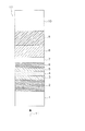
これら光学的相変化形情報記録媒体の例として、4.7GB/DVD−RAMが挙げられる。4.7GB/DVD−RAMの構成は、図8の情報記録媒体12に示すように、基板1上に、レーザ入射側から見て、第1誘電体層2、第1界面層3、記録層4、第2界面層5、第2誘電体層6、光吸収補正層7、反射層8を順に備えた7層構成である。 Examples of these optical phase change information recording media include 4.7 GB / DVD-RAM. As shown in the information recording medium 12 in FIG. 8, the 4.7 GB / DVD-RAM has a structure in which the first dielectric layer 2, the first interface layer 3, and the recording layer are formed on the substrate 1 when viewed from the laser incident side. 4, the second interface layer 5, the second dielectric layer 6, the light absorption correction layer 7, and the reflection layer 8 in this order.
第1誘電体層2と第2誘電体層6は、光学距離を調節して記録層4への光吸収効率を高め、結晶相と非晶質相との反射率変化を大きくして信号強度を大きくする光学的な働きと、記録時に高温となる記録層4から熱に弱い基板1、ダミー基板10等を断熱する熱的な働きがある。誘電体材料としては、例えば、従来から使用されている(ZnS)80(SiO2)20(mol%)が、透明且つ高屈折率で、さらに低熱伝導率であるため断熱性も良く、機械特性及び耐湿性も良好な優れた材料である。The first dielectric layer 2 and the second dielectric layer 6 increase the light absorption efficiency to the recording layer 4 by adjusting the optical distance, and increase the reflectance change between the crystalline phase and the amorphous phase to increase the signal intensity. There is an optical function to increase the thermal resistance, and a thermal function to insulate the substrate 1, the dummy substrate 10, and the like that are vulnerable to heat from the recording layer 4, which becomes a high temperature during recording. As the dielectric material, for example, conventionally used (ZnS) 80 (SiO 2 ) 20 (mol%) is transparent, has a high refractive index, and further has a low thermal conductivity, so that it has good heat insulation and mechanical properties. It is also an excellent material with good moisture resistance.
記録層4には、化合物であるGeTeとSb2Te3を混合したGeTe−Sb2Te3擬二元系相変化材料においてGeの一部をSnで置換した(Ge−Sn)Te−Sb2Te3を含む高速結晶化材料を用いることにより、初期記録書き換え性能のみならず、優れた記録保存性(記録した信号を、長期保存後に再生できるかの指標)、及び書き換え保存性(記録した信号を、長期保存後に消去または書き換えできるかの指標)をも実現している。In the recording layer 4, a GeTe-Sb 2 Te 3 pseudo-binary phase change material obtained by mixing the compound GeTe and Sb 2 Te 3 is substituted with a part of Ge by (Ge—Sn) Te—Sb 2. By using a high-speed crystallization material containing Te 3 , not only the initial recording / rewriting performance, but also excellent recording storability (an index of whether the recorded signal can be reproduced after long-term storage), and rewritable storability (recorded signal) Is also an indicator of whether it can be erased or rewritten after long-term storage.
反射層8は、記録層4に吸収される光量を増大させるという光学的な機能を有する。また、反射層8は、記録層4で生じた熱を速やかに拡散させ、記録層4を非晶質化しやすくするという熱的な機能も有する。さらに、反射層8は、使用する環境から多層膜を保護するという機能も有する。
以上のような技術により、優れた書き換え性能と高い信頼性を達成し、4.7GB/DVD−RAMを商品化するに至った。The reflective layer 8 has an optical function of increasing the amount of light absorbed by the recording layer 4. The reflective layer 8 also has a thermal function of quickly diffusing heat generated in the recording layer 4 and making the recording layer 4 amorphous. Furthermore, the reflective layer 8 also has a function of protecting the multilayer film from the environment in which it is used.
With the technology as described above, excellent rewriting performance and high reliability have been achieved, and 4.7 GB / DVD-RAM has been commercialized.
また、情報記録媒体をさらに大容量化するための技術として、さまざまな技術が検討されている。例えば、光学的相変化形情報記録媒体においては、従来の赤色レーザより短波長の青紫色レーザを用いたり、レーザビームが入射する側の基板の厚さを薄くして開口数(NA)が大きい対物レンズを使用したりすることによって、レーザビームのスポット径をより小さくして高密度の記録を行う技術が検討されている。 In addition, various technologies are being studied as technologies for further increasing the capacity of information recording media. For example, in an optical phase change information recording medium, a numerical aperture (NA) is increased by using a blue-violet laser having a shorter wavelength than a conventional red laser or by reducing the thickness of the substrate on which the laser beam is incident. A technique for performing high-density recording by using an objective lens to make the spot diameter of the laser beam smaller has been studied.
また、2つの情報層を備える光学的相変化形情報記録媒体(以下、2層光学的相変化形情報記録媒体という場合がある)を用いて記録容量を2倍に高め、且つその片側から入射するレーザビームによって2つの情報層の記録再生を行う技術も検討されている(例えば、特許文献1及び特許文献2参照)。この2層光学的相変化形情報記録媒体では、レーザビームの入射側に近い情報層(以下、第1の情報層という)を透過したレーザビームを用いて、レーザビームの入射側から遠い情報層(以下、第2の情報層という)の記録再生を行うため、第1の情報層では透過率を高める必要がある。従来、発明者らは上記のような場合、記録層または反射層の膜厚を極めて薄くして透過率を高めていた。 Further, the recording capacity is doubled by using an optical phase change information recording medium having two information layers (hereinafter sometimes referred to as a two-layer optical phase change information recording medium) and incident from one side. A technique for recording and reproducing two information layers using a laser beam is also being studied (see, for example, Patent Document 1 and Patent Document 2). In this two-layer optical phase change information recording medium, an information layer far from the laser beam incident side is used by using a laser beam transmitted through an information layer close to the laser beam incident side (hereinafter referred to as a first information layer). In order to perform recording / reproduction (hereinafter referred to as a second information layer), it is necessary to increase the transmittance in the first information layer. Conventionally, in the above cases, the inventors have made the recording layer or the reflective layer extremely thin to increase the transmittance.
しかしながら、2層光学的相変化形情報記録媒体の第1の情報層において、記録層及び反射層の膜厚を薄くすると、記録層が結晶相の場合と非晶質相の場合とで反射率の差が小さくなる。このため、第1の情報層の信号品質が低下するという課題がある。
特開2000−36130号公報(第2−11頁、図2) 特開2002−144736号公報(第2−14頁、図3) However, in the first information layer of the two-layer optical phase change information recording medium, when the recording layer and the reflective layer are made thin, the reflectance varies depending on whether the recording layer is a crystalline phase or an amorphous phase. The difference of becomes smaller. For this reason, there exists a subject that the signal quality of a 1st information layer falls.
JP 2000-36130 A (page 2-11, FIG. 2) Japanese Patent Laying-Open No. 2002-144736 (page 2-14, FIG. 3)
本発明は、上記従来の課題を解決し、同時に、情報層の数に関らず情報層における透過率及び信号強度を向上させた光学的情報記録媒体を提供することを目的とする。
上記課題を解決するために、本発明の光学情報記録媒体は、レーザビームの照射によって情報を記録及び/または再生し得る記録層と、Ce及びOを含むCe含有層とを少なくとも有する情報層を一つ以上備えている。An object of the present invention is to solve the above-described conventional problems and at the same time provide an optical information recording medium having improved transmittance and signal intensity in the information layer regardless of the number of information layers.
In order to solve the above problems, an optical information recording medium of the present invention comprises an information layer having at least a recording layer capable of recording and / or reproducing information by laser beam irradiation, and a Ce-containing layer containing Ce and O. Have one or more.
また、本発明の光学的情報記録媒体の製造方法は、レーザビームの照射によって情報を記録及び/または再生し得る記録層を成膜する工程と、CeとOを含むスパッタリングターゲットを用いて、Ce及びOを含むCe含有層を成膜する工程とを少なくとも備えている。 The method for producing an optical information recording medium of the present invention uses a step of forming a recording layer capable of recording and / or reproducing information by laser beam irradiation, and a sputtering target containing Ce and O. And a step of forming a Ce-containing layer containing O.
本発明の光学的情報記録媒体および光学的情報記録媒体の製造方法によれば、光学的情報記録媒体における情報層の信号品質、透過率及び信号強度を向上させることができる。また、本発明の光学的情報記録媒体の製造方法によれば、本発明の光学的情報記録媒体を容易に製造することができる。 According to the optical information recording medium and the method of manufacturing the optical information recording medium of the present invention, the signal quality, transmittance, and signal intensity of the information layer in the optical information recording medium can be improved. Further, according to the method for producing an optical information recording medium of the present invention, the optical information recording medium of the present invention can be easily produced.
情報層を1層備えた本発明の情報記録媒体に関する層構成の一例を示す断面図。Sectional drawing which shows an example of the layer structure regarding the information recording medium of this invention provided with one information layer.
情報層をN層備えた本発明の情報記録媒体に関する層構成の一例を示す断面図。Sectional drawing which shows an example of the layer structure regarding the information recording medium of this invention provided with N information layers.
情報層を2層備えた本発明の情報記録媒体に関する層構成の一例を示す断面図。Sectional drawing which shows an example of the layer structure regarding the information recording medium of this invention provided with two information layers.
本発明の情報記録媒体の記録再生に用いられる記録再生装置に関する構成の一部を模式的に示す図。The figure which shows typically a part of structure regarding the recording / reproducing apparatus used for the recording / reproducing of the information recording medium of this invention.
4.7GB/DVD−RAMに関する層構成の一例を示す断面図。Sectional drawing which shows an example of the layer structure regarding 4.7GB / DVD-RAM.
符号の説明Explanation of symbols
1、14、26、30 基板
2、102、302 第1誘電体層
3、103、303 第1界面層
4、104 記録層
5、105、305 第2界面層
6、106、306 第2誘電体層
7 光吸収補正層
8、108 反射層
9、27 接着層
10、28 ダミー基板
11 レーザビーム
12、15、22、24、29、31、32、37 情報記録媒体
13 透明層
16、18、21 情報層
17、19、20 光学分離層
23 第1情報層
25 第2情報層
33 スピンドルモータ
34 対物レンズ
35 半導体レーザ
36 光学ヘッド
38 記録再生装置
107、307 界面層
109、209、309 Ce含有層
202 第3誘電体層
203 第3界面層
204 第1記録層
205 第4界面層
206 第4誘電体層
208 第1反射層
304 第2記録層
308 第2反射層1, 14, 26, 30 Substrate 2, 102, 302 First dielectric layer 3, 103, 303 First interface layer 4, 104 Recording layer 5, 105, 305 Second interface layer 6, 106, 306 Second dielectric Layer 7 Light absorption correction layer 8, 108 Reflective layer 9, 27 Adhesive layer 10, 28 Dummy substrate 11 Laser beam 12, 15, 22, 24, 29, 31, 32, 37 Information recording medium 13 Transparent layer 16, 18, 21 Information layer 17, 19, 20 Optical separation layer 23 First information layer 25 Second information layer 33 Spindle motor 34 Objective lens 35 Semiconductor laser 36 Optical head 38 Recording / reproducing device 107, 307 Interface layer 109, 209, 309 Ce-containing layer 202 Third dielectric layer 203 Third interface layer 204 First recording layer 205 Fourth interface layer 206 Fourth dielectric layer 208 First reflective layer 304 Second recording Layer 308 Second reflective layer
以下、本発明の実施の形態について、図面を参照しながら説明する。なお、以下の実施の形態は一例であり、本発明は以下の実施の形態に限定されない。また、以下の実施の形態では、同一の部分については同一の符号を付して重複する説明を省略する場合がある。 Hereinafter, embodiments of the present invention will be described with reference to the drawings. The following embodiment is an example, and the present invention is not limited to the following embodiment. Further, in the following embodiments, the same portions may be denoted by the same reference numerals and redundant description may be omitted.
(実施の形態1)
実施の形態1では、本発明の光学的情報記録媒体の一例を説明する。本実施の形態の情報記録媒体15の一部断面図を図1に示す。情報記録媒体15は、レーザビーム11の照射によって情報の記録再生が可能な光学的情報記録媒体である。
情報記録媒体15は、基板14上に成膜された情報層16、及び透明層13により構成されている。(Embodiment 1)
In the first embodiment, an example of the optical information recording medium of the present invention will be described. A partial cross-sectional view of the information recording medium 15 of the present embodiment is shown in FIG. The information recording medium 15 is an optical information recording medium capable of recording and reproducing information by irradiation with the laser beam 11.
The information recording medium 15 includes an information layer 16 formed on the substrate 14 and a transparent layer 13.
透明層13の材料は、光硬化性樹脂(特に紫外線硬化性樹脂)や遅効性樹脂等の樹脂、あるいは誘電体等からなり、使用するレーザビーム11に対して光吸収が小さいことが好ましく、短波長域において光学的に複屈折が小さいことが好ましい。この場合、透明層13は、樹脂によって第1誘電体層102に貼り合わせることが可能である。なお、透明層13の他の材料としては、透明な円盤状のポリカーボネート、アモルファスポリオレフィン、PMMA等の樹脂、またはガラス等を用いてもよい。 The material of the transparent layer 13 is made of a resin such as a photo-curing resin (particularly an ultraviolet curable resin) or a slow-acting resin, or a dielectric, and preferably has a small light absorption with respect to the laser beam 11 to be used. It is preferable that birefringence is optically small in the wavelength region. In this case, the transparent layer 13 can be bonded to the first dielectric layer 102 with a resin. In addition, as another material of the transparent layer 13, you may use resin, such as a transparent disk shaped polycarbonate, amorphous polyolefin, PMMA, or glass.
ここで、レーザビーム11の波長λは、レーザビーム11を集光した際のスポット径が波長λによって決まってしまう(波長λが短いほど、より小さなスポット径に集光可能)ため、高密度記録の場合、特に450nm以下であることが好ましく、また、350nm未満では透明層13等による光吸収が大きくなってしまうため、350nm〜450nmの範囲内であることがより好ましい。 Here, the wavelength λ of the laser beam 11 is determined by the wavelength λ when the laser beam 11 is focused (the shorter the wavelength λ, the smaller the spot diameter can be focused). In this case, the thickness is particularly preferably 450 nm or less, and if it is less than 350 nm, the light absorption by the transparent layer 13 and the like is increased, and therefore, it is more preferably in the range of 350 nm to 450 nm.
基板14は、透明で円盤状の基板である。基板14の情報層16側の表面には、必要に応じてレーザビームを導くための案内溝が形成されていてもよい。一方、基板14の情報層16側と反対側の表面は、平滑であることが好ましい。 The substrate 14 is a transparent and disk-shaped substrate. A guide groove for guiding a laser beam may be formed on the surface of the substrate 14 on the information layer 16 side, if necessary. On the other hand, the surface of the substrate 14 opposite to the information layer 16 side is preferably smooth.
基板14の材料としては、例えば、ポリカーボネート、アモルファスポリオレフィン、及びPMMA等の樹脂、またはガラスを用いることができる。特に、転写性・量産性に優れ、低コストであることから、ポリカーボネートが有用である。 As a material of the substrate 14, for example, a resin such as polycarbonate, amorphous polyolefin, and PMMA, or glass can be used. In particular, polycarbonate is useful because of its excellent transferability and mass productivity and low cost.
基板14の厚さは、十分な強度があり、且つ情報記録媒体15の厚さが1.2mm程度となるように、0.5mm〜1.2mmの範囲内であることが好ましい。例えば、透明層13の厚さが0.6mm程度(NA=0.6で良好な記録再生が可能な厚さ)の場合は、5.5mm〜6.5mmの範囲内であることが好ましい。また、透明層13の厚さが0.1mm程度(NA=0.85で良好な記録再生が可能な厚さ)の場合は、1.05mm〜1.15mmの範囲内であることが好ましい。 The thickness of the substrate 14 is preferably in a range of 0.5 mm to 1.2 mm so that the strength is sufficient and the thickness of the information recording medium 15 is about 1.2 mm. For example, when the thickness of the transparent layer 13 is about 0.6 mm (thickness at which NA = 0.6 enables good recording / reproduction), the thickness is preferably in the range of 5.5 mm to 6.5 mm. Moreover, when the thickness of the transparent layer 13 is about 0.1 mm (thickness at which NA = 0.85 can be satisfactorily recorded / reproduced), the thickness is preferably in the range of 1.05 mm to 1.15 mm.
次に、情報層16の構成について詳細に説明する。
情報層16は、レーザビーム11の入射側から順に配置された第1誘電体層102、第1界面層103、記録層104、第2界面層105、第2誘電体層106、反射層108、及びCe含有層109を有する。Next, the configuration of the information layer 16 will be described in detail.
The information layer 16 includes a first dielectric layer 102, a first interface layer 103, a recording layer 104, a second interface layer 105, a second dielectric layer 106, a reflective layer 108, which are arranged in order from the incident side of the laser beam 11. And a Ce-containing layer 109.
第1誘電体層102は、誘電体からなる。この第1誘電体層102は、記録層104の酸化、腐食、及び変形等を防止する働きと、光学距離を調整して記録層104の光吸収効率を高める働きと、記録前後の反射光量の変化を大きくして信号強度を大きくする働きとを有する。 The first dielectric layer 102 is made of a dielectric. The first dielectric layer 102 functions to prevent oxidation, corrosion, deformation, etc. of the recording layer 104, to increase the light absorption efficiency of the recording layer 104 by adjusting the optical distance, and to reflect the amount of reflected light before and after recording. It has the function of increasing the signal intensity by increasing the change.
第1誘電体層102の材料としては、例えば、TiO2、ZrO2、HfO2、ZnO、Nb2O5、Ta2O5、SiO2、SnO2、Al2O3、Bi2O3、Cr2O3、Ga2O3、In2O3、Sc2O3、Y2O3、La2O3、Gd2O3、Dy2O3、Yb2O3、MgO、CeO2、TeO2等の酸化物を用いることができる。また、C−N、Ti−N、Zr−N、Nb−N、Ta−N、Si−N、Ge−N、Cr−N、Al−N、Ge−Si−N、Ge−Cr−N等の窒化物を用いることもできる。さらに、ZnS等の硫化物、SiC等の炭化物、LaF3等の弗化物、及びCを用いることもできる。さらに、上記材料の混合物を用いることもできる。例えば、ZnSとSiO2との混合物であるZnS−SiO2が、第1誘電体層102の材料として特に優れている。それは、ZnS−SiO2は、非晶質材料であり、屈折率が高く、成膜速度が速く、さらに機械特性及び耐湿性が良好であるためである。Examples of the material of the first dielectric layer 102 include TiO 2 , ZrO 2 , HfO 2 , ZnO, Nb 2 O 5 , Ta 2 O 5 , SiO 2 , SnO 2 , Al 2 O 3 , Bi 2 O 3 , cr 2 O 3, Ga 2 O 3, In 2 O 3, Sc 2 O 3, Y 2 O 3, La 2 O 3, Gd 2 O 3, Dy 2 O 3, Yb 2 O 3, MgO, CeO 2, An oxide such as TeO 2 can be used. Also, C-N, Ti-N, Zr-N, Nb-N, Ta-N, Si-N, Ge-N, Cr-N, Al-N, Ge-Si-N, Ge-Cr-N, etc. Nitride of the above can also be used. Furthermore, sulfides such as ZnS, carbides such as SiC, fluorides such as LaF 3 , and C can also be used. Furthermore, a mixture of the above materials can also be used. For example, ZnS-SiO 2, which is a mixture of ZnS and SiO 2 is particularly excellent as the material of the first dielectric layer 102. This is because ZnS—SiO 2 is an amorphous material, has a high refractive index, a high deposition rate, and good mechanical properties and moisture resistance.
第1誘電体層102の膜厚は、マトリクス法に基づく計算により、記録層104が結晶相である場合と非晶質相である場合とで反射光量の変化が大きくなる条件を満足するように、一般的には厳密に決定することができる。 The film thickness of the first dielectric layer 102 satisfies the condition that the change in the amount of reflected light is large between the case where the recording layer 104 is in the crystalline phase and the case where it is in the amorphous phase, based on the calculation based on the matrix method. In general, it can be determined strictly.
第1界面層103は、繰り返し記録によって、第1誘電体層102と記録層104との間で生じる物質移動を防止する働きをする。
第1界面層103の材料としては、高パワーのレーザビーム11を照射した際に、第1界面層103が溶けて記録層104に混入することを防止するために、光の吸収が少なく、情報記録の際に溶けないような高い融点を有する材料であることが好ましい。第1界面層103の材料が混入すると、記録層104の組成が変わり、書き換え性能が著しく低下するためである。加えて、第1界面層103と記録層104との密着性が、情報記録媒体15の信頼性確保に重要であることから、記録層104との密着性の良い材料であることが好ましい。The first interface layer 103 functions to prevent mass transfer between the first dielectric layer 102 and the recording layer 104 due to repeated recording.
As the material of the first interface layer 103, in order to prevent the first interface layer 103 from being melted and mixed into the recording layer 104 when irradiated with the high-power laser beam 11, there is little light absorption, information It is preferable that the material has a high melting point that does not melt during recording. This is because when the material of the first interface layer 103 is mixed, the composition of the recording layer 104 is changed and the rewriting performance is remarkably deteriorated. In addition, since the adhesion between the first interface layer 103 and the recording layer 104 is important for ensuring the reliability of the information recording medium 15, a material having good adhesion with the recording layer 104 is preferable.
具体的な材料としては、第1誘電体層102と同様の系の材料を用いることができる。その中でも、CrとOを含む材料を用いると、記録層104の結晶化をより促進することができるため好ましい。特に、Cr2O3を酸化物として含むことが好ましい。Cr2O3は、記録層104との密着性が良い材料である。また、GaとOを含む材料を用いることもできる。特に、Ga2O3を酸化物として含むことが好ましい。Ga2O3も、記録層104との密着性が良い材料である。また、InとOを含む材料を用いることもできる。特に、In2O3を酸化物として含むことが好ましい。In2O3も、記録層104との密着性が良い材料である。これらの他に、第1界面層103は、Zr、Hf及びYから選ばれる少なくとも一つの元素をさらに含んでもよい。特に、ZrO2及びHfO2は、透明で融点が約2700〜2800℃と高く、且つ酸化物の中では熱伝導率が低い材料で、繰り返し書き換え性能が良い。また、Y2O3は透明な材料で、且つZrO2及びHfO2を安定化させる働きがある。この3種類の酸化物を混合することによって、記録層104と部分的に接して形成しても、繰り返し書き換え性能に優れ、信頼性の高い情報記録媒体15が実現できる。なお、第1界面層103中のCr2O3、Ga2O3、またはIn2O3の含有量は、記録層104との密着性を確保するために、10mol%以上あることが好ましい。さらに、第1界面層103中のCr2O3の含有量は、第1界面層103での光吸収を小さく保つために、70mol%以下であることが好ましい。As a specific material, a material similar to that of the first dielectric layer 102 can be used. Among them, it is preferable to use a material containing Cr and O because crystallization of the recording layer 104 can be further promoted. In particular, it is preferable to contain Cr 2 O 3 as an oxide. Cr 2 O 3 is a material having good adhesion to the recording layer 104. A material containing Ga and O can also be used. In particular, Ga 2 O 3 is preferably included as an oxide. Ga 2 O 3 is also a material having good adhesion to the recording layer 104. A material containing In and O can also be used. In particular, In 2 O 3 is preferably included as an oxide. In 2 O 3 is also a material having good adhesion to the recording layer 104. In addition to these, the first interface layer 103 may further include at least one element selected from Zr, Hf, and Y. In particular, ZrO 2 and HfO 2 are materials that are transparent, have a high melting point of about 2700 to 2800 ° C., and have a low thermal conductivity among oxides, and have good repeated rewriting performance. Y 2 O 3 is a transparent material and has a function of stabilizing ZrO 2 and HfO 2 . By mixing these three kinds of oxides, the information recording medium 15 having excellent repetitive rewriting performance and high reliability can be realized even when formed in partial contact with the recording layer 104. The content of Cr 2 O 3 , Ga 2 O 3 , or In 2 O 3 in the first interface layer 103 is preferably 10 mol% or more in order to ensure adhesion with the recording layer 104. Furthermore, the content of Cr 2 O 3 in the first interface layer 103 is preferably 70 mol% or less in order to keep light absorption in the first interface layer 103 small.
さらに、第1界面層103の材料として、Siを含む材料を用いても良い。例えば、SiO2を含ませることにより、透明性が高くなり、記録性能に優れた第1情報層16を実現できる。第1界面層103中のSiO2の含有量は、5mol%以上あることが好ましく、さらには記録層104との密着性を確保するために50mol%以下であることが好ましい。10mol%以上40mol%以下であればより好ましい。Further, a material containing Si may be used as the material of the first interface layer 103. For example, by including SiO 2 , the first information layer 16 having high transparency and excellent recording performance can be realized. The content of SiO 2 in the first interface layer 103 is preferably 5 mol% or more, and more preferably 50 mol% or less in order to ensure adhesion with the recording layer 104. More preferably, it is 10 mol% or more and 40 mol% or less.
第1界面層103の膜厚は、第1界面層103での光吸収によって情報層16の記録前後の反射光量の変化が小さくならないように、0.5nm〜15nmの範囲内であることが望ましく、1nm〜7nmの範囲内にあることがより好ましい。 The film thickness of the first interface layer 103 is preferably in the range of 0.5 nm to 15 nm so that the change in the amount of reflected light before and after recording of the information layer 16 does not become small due to light absorption in the first interface layer 103. More preferably, it is in the range of 1 nm to 7 nm.
第2界面層105は、第1界面層103と同様に、繰り返し記録によって第2誘電体層106と記録層104との間で生じる物質移動を防止する働きをする。
具体的な材料としては、第1誘電体層102と同様の系の材料を用いることができる。その中でも、GaとOを含む材料を用いることが好ましい。特に、Ga2O3を酸化物として含むことが好ましい。また、CrとOを含む材料を用いることもできる。特に、Cr2O3を酸化物として含むことが好ましい。また、InとOを含む材料を用いることもできる。その中でも、In2O3を酸化物として含むことが好ましい。これらの他に、第2界面層105と同様に、Zr、Hf及びYから選ばれる少なくとも一つの元素をさらに含んでもよいし、さらにSiを含む材料を用いても良い。第2界面層105は第1界面層103より密着性が悪い傾向にあるため、第2界面層105中のCr2O3、Ga2O3またはIn2O3の含有量は、第1界面層103のそれより多い20mol%以上であることが好ましい。Similar to the first interface layer 103, the second interface layer 105 functions to prevent mass transfer between the second dielectric layer 106 and the recording layer 104 due to repeated recording.
As a specific material, a material similar to that of the first dielectric layer 102 can be used. Among these, it is preferable to use a material containing Ga and O. In particular, Ga 2 O 3 is preferably included as an oxide. A material containing Cr and O can also be used. In particular, it is preferable to contain Cr 2 O 3 as an oxide. A material containing In and O can also be used. Among these, it is preferable to contain In 2 O 3 as an oxide. In addition to these, like the second interface layer 105, at least one element selected from Zr, Hf, and Y may be further included, and a material containing Si may be further used. Since the second interface layer 105 tends to have poorer adhesion than the first interface layer 103, the content of Cr 2 O 3 , Ga 2 O 3 or In 2 O 3 in the second interface layer 105 is It is preferably 20 mol% or more, which is higher than that of the layer 103.
第2界面層105の膜厚は、0.5nm〜75nmの範囲内であることが望ましく、2nm〜40nmの範囲内にあることがより好ましい。この範囲内にすることによって、記録層104で発生した熱を、効果的に反射層108側に拡散させることができる。 The film thickness of the second interface layer 105 is preferably in the range of 0.5 nm to 75 nm, and more preferably in the range of 2 nm to 40 nm. By making it within this range, the heat generated in the recording layer 104 can be effectively diffused to the reflective layer 108 side.
第2誘電体層106は、第2界面層105と反射層108との間に配置され、その材料としては、第1誘電体層102と同様の系を用いることができる。第2誘電体層106の膜厚は、2nm〜75nmの範囲内であることが好ましく、2nm〜40nmの範囲内であることがより好ましい。この範囲内にすることによって、記録層104で発生した熱を効果的に反射層108側に拡散させることができる。 The second dielectric layer 106 is disposed between the second interface layer 105 and the reflective layer 108, and a material similar to that of the first dielectric layer 102 can be used as the material thereof. The film thickness of the second dielectric layer 106 is preferably in the range of 2 nm to 75 nm, and more preferably in the range of 2 nm to 40 nm. By setting it within this range, the heat generated in the recording layer 104 can be effectively diffused to the reflective layer 108 side.
また、記録層104の材料としては、レーザビーム11の照射によって結晶相と非晶質相との間で相変化を起こす材料を用いる。例えば、Ge、Te、M2(但し、M2は、Sb、Bi及びInの少なくともいずれか一つの元素)を含む可逆的な相変化を起こす材料を用いることができる。具体的には、記録層104は、GeAM2BTe3+Aと表される材料で形成できる。ここで、Aが0<A≦60の関係を満たす場合には、非晶質相が安定且つ低い転送レートでの記録保存性が良好で、融点の上昇と結晶化速度の低下が少なく且つ高い転送レートでの書き換え保存性が良好となる。さらには、Aは、4≦A≦40の関係を満たすことがより好ましい。また、Bが1.5≦B≦7の関係を満たす場合には、非晶質相が安定で且つ結晶化速度の低下が少なくなるため好ましく、2≦B≦4の関係を満たすことがより好ましい。Further, as the material of the recording layer 104, a material that causes a phase change between a crystalline phase and an amorphous phase by irradiation with the laser beam 11 is used. For example, a material that causes a reversible phase change including Ge, Te, and M2 (where M2 is at least one element of Sb, Bi, and In) can be used. Specifically, the recording layer 104 can be formed of a material expressed as Ge A M2 B Te 3 + A. Here, when A satisfies the relationship of 0 <A ≦ 60, the amorphous phase is stable and the recording stability at a low transfer rate is good, and the rise in melting point and the decrease in crystallization speed are small and high. The rewrite storability at the transfer rate is improved. Furthermore, it is more preferable that A satisfies the relationship of 4 ≦ A ≦ 40. Further, when B satisfies the relationship of 1.5 ≦ B ≦ 7, it is preferable that the amorphous phase is stable and the decrease in the crystallization rate is reduced, and the relationship of 2 ≦ B ≦ 4 is more satisfied. preferable.
また、記録層104には、組成式(Ge−M3)AM2BTe3+A(但し、M3はSn及びPbから選ばれる少なくとも一つの元素)で表される可逆的な相変化を起こす材料を用いても良い。この場合、Geを置換した元素M3が結晶化能を向上させるため、記録層104の膜厚が薄い場合でも十分な消去率が得られる。元素M2としては、毒性がないという点でSnがより好ましい。この材料を用いる場合も、0<A≦60(より好ましくは4≦A≦40)、且つ1.5≦B≦7(より好ましくは2≦B≦4)であることが好ましい。また、他の材料としては、例えば、SbとM4(但し、M4はV、Mn、Ga、Ge、Se、Ag、In、Sn、Te、Pb、Bi、Tb、Dy及びAuから選ばれる少なくとも一つの元素)を含む可逆的な相変化を起こす材料を用いることもできる。具体的には、SbXM4100−X(原子%)で表される材料を用いる。Xが、50≦X≦95を満たす場合には、記録層104が結晶相の場合と非晶質相の場合とで情報記録媒体15の反射率差を大きくできるため、良好な記録再生特性が得られる。その中でも、75≦X≦95の場合には、結晶化速度が特に速く、高い転送レートにおいて良好な書き換え性能が得られる。また、50≦X≦75の場合には、非晶質相が特に安定で、低い転送レートにおいて良好な記録性能が得られる。The recording layer 104 is made of a material that causes a reversible phase change represented by a composition formula (Ge-M3) A M2 B Te 3 + A (where M3 is at least one element selected from Sn and Pb). May be. In this case, since the element M3 substituted with Ge improves the crystallization ability, a sufficient erasing rate can be obtained even when the recording layer 104 is thin. As the element M2, Sn is more preferable because it is not toxic. Also in the case of using this material, it is preferable that 0 <A ≦ 60 (more preferably 4 ≦ A ≦ 40) and 1.5 ≦ B ≦ 7 (more preferably 2 ≦ B ≦ 4). Other materials include, for example, Sb and M4 (where M4 is at least one selected from V, Mn, Ga, Ge, Se, Ag, In, Sn, Te, Pb, Bi, Tb, Dy, and Au). It is also possible to use a material that causes a reversible phase change including two elements. Specifically, a material represented by Sb X M4 100-X (atomic%) is used. When X satisfies 50 ≦ X ≦ 95, the difference in reflectance of the information recording medium 15 can be increased between the case where the recording layer 104 is in the crystalline phase and the case where the recording layer 104 is in the amorphous phase. can get. Among them, when 75 ≦ X ≦ 95, the crystallization speed is particularly fast, and good rewriting performance can be obtained at a high transfer rate. When 50 ≦ X ≦ 75, the amorphous phase is particularly stable, and good recording performance can be obtained at a low transfer rate.
記録層104の膜厚は、情報層16の記録感度を高くするため、6nm〜15nmの範囲内であることが好ましい。この範囲内において、記録層104が厚い場合には、熱の面内方向への拡散による隣接領域への熱的影響が大きくなる。また、記録層104が薄い場合には、情報層16の反射率が小さくなる。したがって、記録層104の膜厚は、8nm〜13nmの範囲内であることがより好ましい。 The film thickness of the recording layer 104 is preferably in the range of 6 nm to 15 nm in order to increase the recording sensitivity of the information layer 16. Within this range, when the recording layer 104 is thick, the thermal influence on the adjacent region due to the diffusion of heat in the in-plane direction becomes large. Further, when the recording layer 104 is thin, the reflectance of the information layer 16 becomes small. Therefore, the thickness of the recording layer 104 is more preferably in the range of 8 nm to 13 nm.
なお、記録層104の材料としては、Te−Pd−Oと表される不可逆な相変化を起こす材料を用いることもできる。この場合の記録層104の膜厚は、10nm〜40nmの範囲内であることが好ましい。 As a material for the recording layer 104, a material that causes an irreversible phase change represented by Te—Pd—O may be used. In this case, the thickness of the recording layer 104 is preferably in the range of 10 nm to 40 nm.
反射層108は、記録層104に吸収される光量を増大させるという光学的な機能を有する。また、反射層108は、記録層104で生じた熱を速やかに拡散させ、記録層104を非晶質化しやすくするという熱的な機能も有する。さらに、反射層108は、使用する環境から多層膜を保護するという機能も有する。 The reflective layer 108 has an optical function of increasing the amount of light absorbed by the recording layer 104. The reflective layer 108 also has a thermal function of quickly diffusing heat generated in the recording layer 104 and making the recording layer 104 easily amorphous. Furthermore, the reflective layer 108 also has a function of protecting the multilayer film from the environment in which it is used.
反射層108の材料としては、例えば、Ag、Au、Cu及びAlといった熱伝導率が高い単体金属を用いることができる。また、Al−Cr、Al−Ti、Al−Ni、Al−Cu、Au−Pd、Au−Cr、Ag−Pd、Ag−Pd−Cu、Ag−Pd−Ti、Ag−Ru−Au、Ag−Cu−Ni、Ag−Zn−Al、Ag−Nd−Au、Ag−Nd−Cu、Ag−Bi、Ag−Ga、Ag−Ga−In、Ag−In、Ag−In−SnまたはCu−Siといった合金を用いることもできる。特に、Ag合金は熱伝導率が大きいため、反射層108の材料として好ましい。 As a material of the reflective layer 108, for example, a single metal having a high thermal conductivity such as Ag, Au, Cu, and Al can be used. Al-Cr, Al-Ti, Al-Ni, Al-Cu, Au-Pd, Au-Cr, Ag-Pd, Ag-Pd-Cu, Ag-Pd-Ti, Ag-Ru-Au, Ag- Cu-Ni, Ag-Zn-Al, Ag-Nd-Au, Ag-Nd-Cu, Ag-Bi, Ag-Ga, Ag-Ga-In, Ag-In, Ag-In-Sn or Cu-Si An alloy can also be used. In particular, an Ag alloy is preferable as a material for the reflective layer 108 because of its high thermal conductivity.
反射層108の膜厚は、熱拡散機能が十分となるように、30nm以上であることが好ましい。但し、この範囲内であっても、反射層108が200nmより厚い場合には、その熱拡散機能が大きくなりすぎて情報層16の記録感度が低下する。したがって、反射層108の膜厚は、30nm〜200nmの範囲内であることがより好ましい。 The thickness of the reflective layer 108 is preferably 30 nm or more so that the thermal diffusion function is sufficient. However, even within this range, if the reflective layer 108 is thicker than 200 nm, the thermal diffusion function becomes too large, and the recording sensitivity of the information layer 16 decreases. Therefore, the thickness of the reflective layer 108 is more preferably in the range of 30 nm to 200 nm.
Ce含有層109は、基板14と反射層108の間に配置され、記録層104で発生した熱を効果的に拡散させる効果を有する。また、反射層108にAg合金を用いた場合に、Agは水分を接触することで腐食し易いため、Ce含有層109を設けると反射層108を水分から保護することもできる。さらには、反射層108の表面性を向上させる役割も果たす。 The Ce-containing layer 109 is disposed between the substrate 14 and the reflective layer 108 and has an effect of effectively diffusing heat generated in the recording layer 104. In addition, when an Ag alloy is used for the reflective layer 108, Ag easily corrodes when it comes into contact with moisture. Therefore, when the Ce-containing layer 109 is provided, the reflective layer 108 can be protected from moisture. Furthermore, it plays a role of improving the surface properties of the reflective layer 108.
Ce含有層109の材料としては、CeとOを含む誘電体を用いることができる。この場合、CeO2を酸化物として含むことが好ましい。また、Ce含有層109には、CeとTiとOを含む誘電体を用いることもできる。この場合、CeO2とTiO2との混合物である、CeO2−TiO2を用いることもできる。また、Ce含有層109としては、さらにM1(但し、M1はNb及びBiから選ばれる少なくとも一つの元素)を含む誘電体を用いることもできる。この場合、D(但し、DはNb2O5及びBi2O3から選ばれる少なくとも一つの化合物)を酸化物として含む誘電体を用いることもできる。As a material for the Ce-containing layer 109, a dielectric containing Ce and O can be used. In this case, it is preferable to contain CeO 2 as an oxide. For the Ce-containing layer 109, a dielectric containing Ce, Ti, and O can also be used. In this case, a mixture of CeO 2 and TiO 2, can also be used CeO 2 -TiO 2. Further, as the Ce-containing layer 109, a dielectric containing M1 (where M1 is at least one element selected from Nb and Bi) can also be used. In this case, a dielectric including D (wherein D is at least one compound selected from Nb 2 O 5 and Bi 2 O 3 ) as an oxide can also be used.
情報層16において、反射層108と第2誘電体層106の間に、界面層107を配置してもよい。
界面層107の材料としては、反射層108について説明した材料より熱伝導率の低い材料を用いることができる。例えば、反射層108にAg合金を用いた場合、界面層107には、AlまたはAl合金を用いることができる。他に、界面層107には、Cr、Ni、Si、C等の元素や、TiO2、ZrO2、HfO2、ZnO、Nb2O5、Ta2O5、SiO2、SnO2、Al2O3、Bi2O3、Cr2O3、Ga2O3、In2O3等の酸化物を用いることができる。また、C−N、Ti−N、Zr−N、Nb−N、Ta−N、Si−N、Ge−N、Cr−N、Al−N、Ge−Si−N、Ge−Cr−N等の窒化物を用いることもできる。また、ZnS等の硫化物、SiC等の炭化物、LaF3等の弗化物、及びCを用いることもできる。さらに、上記材料の混合物を用いることもできる。In the information layer 16, the interface layer 107 may be disposed between the reflective layer 108 and the second dielectric layer 106.
As the material of the interface layer 107, a material having a lower thermal conductivity than the material described for the reflective layer 108 can be used. For example, when an Ag alloy is used for the reflective layer 108, Al or an Al alloy can be used for the interface layer 107. In addition, the interface layer 107 includes elements such as Cr, Ni, Si, and C, TiO 2 , ZrO 2 , HfO 2 , ZnO, Nb 2 O 5 , Ta 2 O 5 , SiO 2 , SnO 2 , and Al 2. O 3 , Bi 2 O 3 , Cr 2 O 3 , Ga 2 O 3 , In 2 O 3 and other oxides can be used. Also, C-N, Ti-N, Zr-N, Nb-N, Ta-N, Si-N, Ge-N, Cr-N, Al-N, Ge-Si-N, Ge-Cr-N, etc. Nitride of the above can also be used. Further, sulfides such as ZnS, carbides such as SiC, fluorides such as LaF 3 , and C can also be used. Furthermore, a mixture of the above materials can also be used.
界面層107の膜厚は、3nm〜100nm、より好ましくは10nm〜50nmの範囲内であればよい。
情報層16においては、記録層104が結晶相である場合の反射率をRC(%)、及び記録層104が非晶質相である場合の反射率をRA(%)とすると、RA<RCを満たすことが好ましい。これにより、情報が記録されていない初期の状態において反射率が高くなり、安定に記録再生動作を行うことができる。また、反射率差(RC−RA)を大きくして良好な記録再生特性が得られるように、RC及びRAは、0.2≦RA≦10且つ12≦RC≦40を満たすことが好ましく、さらには0.2≦RA≦5且つ12≦RC≦30を満たすことが好ましい。The film thickness of the interface layer 107 may be in the range of 3 nm to 100 nm, more preferably 10 nm to 50 nm.
In the information layer 16, R C (%) is the reflectance when the recording layer 104 is in the crystalline phase, and R A (%) is the reflectance when the recording layer 104 is in the amorphous phase. It is preferable to satisfy A < RC . As a result, the reflectance increases in an initial state where no information is recorded, and a recording / reproducing operation can be performed stably. In addition, R C and R A satisfy 0.2 ≦ R A ≦ 10 and 12 ≦ R C ≦ 40 so as to obtain a good recording / reproduction characteristic by increasing the difference in reflectance (R C −R A ). It is preferable to satisfy, and further preferably 0.2 ≦ R A ≦ 5 and 12 ≦ R C ≦ 30.
以下、情報記録媒体15の製造方法について説明する。
まず、基板14(厚さが例えば1.1mm)上に情報層16を積層する。情報層16は、単層膜、または多層膜からなる。これらの各層は、各層の材料となるスパッタリングターゲットを成膜装置内で順次スパッタリングすることによって形成できる。Hereinafter, a method for manufacturing the information recording medium 15 will be described.
First, the information layer 16 is laminated on the substrate 14 (having a thickness of 1.1 mm, for example). The information layer 16 is composed of a single layer film or a multilayer film. Each of these layers can be formed by sequentially sputtering a sputtering target as a material of each layer in a film forming apparatus.
具体的には、まず基板14上にCe含有層109を成膜する。Ce含有層109は、Ce含有層109を構成する化合物からなるスパッタリングターゲット(例えば、CeO2)を、Arガス雰囲気中、またはArガスとO2ガスとの混合ガス雰囲気中でスパッタリングすることによって形成できる。また、Ce含有層109は、Ce含有層109を構成する金属からなるスパッタリングターゲット(例えば、Ce)を、ArガスとO2ガスとの混合ガス雰囲気中で反応性スパッタリングすることによっても形成できる。Specifically, a Ce-containing layer 109 is first formed on the substrate 14. The Ce-containing layer 109 is formed by sputtering a sputtering target (for example, CeO 2 ) made of a compound constituting the Ce-containing layer 109 in an Ar gas atmosphere or a mixed gas atmosphere of Ar gas and O 2 gas. it can. The Ce-containing layer 109 can also be formed by reactive sputtering of a sputtering target (eg, Ce) made of a metal constituting the Ce-containing layer 109 in a mixed gas atmosphere of Ar gas and O 2 gas.
また、Ce含有層109は、CeO2、TiO2、またはDの各々のスパッタリングターゲットを、複数の電源を用いて同時にスパッタリングすることによっても形成できる。また、Ce含有層109は、CeO2、TiO2、またはDのうちいずれかの化合物を組み合わせた2元系スパッタリングターゲットや3元系スパッタリングターゲット等を、複数の電源を用いて同時にスパッタリングすることによっても形成できる。スパッタリングは、Arガス雰囲気中、またはArガスとO2ガスとの混合ガス雰囲気中で行えばよい。The Ce-containing layer 109 can also be formed by simultaneously sputtering each of CeO 2 , TiO 2 , or D using a plurality of power supplies. In addition, the Ce-containing layer 109 is formed by simultaneously sputtering a binary sputtering target, a ternary sputtering target, or the like that is a combination of any of CeO 2 , TiO 2 , and D using a plurality of power supplies. Can also be formed. Sputtering may be performed in an Ar gas atmosphere or a mixed gas atmosphere of Ar gas and O 2 gas.
さらに、Ce含有層109は、Ce、Ti、またはM1の各々のスパッタリングターゲットを、複数の電源を用いて同時にスパッタリングすることによっても形成できる。また、Ce含有層109は、Ce、Ti、またはM1のうちいずれかの金属を組み合わせた2元系スパッタリングターゲットや3元系スパッタリングターゲット等を、複数の電源を用いて同時にスパッタリングすることによっても形成できる。これらの場合、スパッタリングは、ArガスとO2ガスとの混合ガス雰囲気中で反応性スパッタリングを行えばよい。Further, the Ce-containing layer 109 can be formed by simultaneously sputtering each of Ce, Ti, or M1 using a plurality of power supplies. Further, the Ce-containing layer 109 is also formed by simultaneously sputtering a binary sputtering target, a ternary sputtering target, or the like in which any one of Ce, Ti, or M1 is combined using a plurality of power supplies. it can. In these cases, the sputtering may be carried out in a mixed gas atmosphere of Ar gas and O 2 gas.
続いて、基板14、またはCe含有層109上に反射層108を成膜する。反射層108は、反射層108を構成する金属または合金からなるスパッタリングターゲットを、Arガス雰囲気中、またはArガスと反応ガス(O2ガス及びN2ガスから選ばれる少なくとも一つのガス)との混合ガス雰囲気中でスパッタリングすることによって形成できる。Subsequently, the reflective layer 108 is formed on the substrate 14 or the Ce-containing layer 109. The reflective layer 108 is formed by mixing a sputtering target made of a metal or an alloy constituting the reflective layer 108 in an Ar gas atmosphere or a mixture of Ar gas and a reactive gas (at least one gas selected from O 2 gas and N 2 gas). It can be formed by sputtering in a gas atmosphere.
続いて、反射層108上に、界面層107を成膜する。界面層107は、界面層107を構成する元素または化合物からなるスパッタリングターゲットを、Arガス雰囲気中、またはArガスと反応ガスとの混合ガス雰囲気中でスパッタリングすることによって形成できる。 Subsequently, an interface layer 107 is formed on the reflective layer 108. The interface layer 107 can be formed by sputtering a sputtering target made of an element or a compound constituting the interface layer 107 in an Ar gas atmosphere or a mixed gas atmosphere of Ar gas and a reactive gas.
続いて、反射層108、または界面層107上に、第2誘電体層106を成膜する。第2誘電体層106は、界面層107と同様の方法で形成できる。
続いて、反射層108、界面層107、または第2誘電体層106上に、第2界面層105を成膜する。第2界面層105は、界面層107と同様の方法で形成できる。Subsequently, the second dielectric layer 106 is formed on the reflective layer 108 or the interface layer 107. The second dielectric layer 106 can be formed by the same method as the interface layer 107.
Subsequently, the second interface layer 105 is formed on the reflective layer 108, the interface layer 107, or the second dielectric layer 106. The second interface layer 105 can be formed by a method similar to that for the interface layer 107.
続いて、第2界面層105上に、記録層104を成膜する。記録層104は、その組成に応じて、Ge−Te−M2合金からなるスパッタリングターゲット、Ge−M3−Te−M2合金からなるスパッタリングターゲット、Sb−M4合金からなるスパッタリングターゲット、またはTe−Pd合金からなるスパッタリングターゲットを、一つの電源を用いてスパッタリングすることによって形成できる。 Subsequently, the recording layer 104 is formed on the second interface layer 105. The recording layer 104 is made of a sputtering target made of a Ge—Te—M2 alloy, a sputtering target made of a Ge—M3—Te—M2 alloy, a sputtering target made of an Sb—M4 alloy, or a Te—Pd alloy, depending on its composition. The resulting sputtering target can be formed by sputtering using a single power source.
スパッタリングの雰囲気ガスには、Arガス、Krガス、またはArガスと反応ガスとの混合ガス、またはKrガスと反応ガスとの混合ガスを用いることができる。また、記録層104は、Ge、Te、M2、M3、Sb、M4、またはPdの各々のスパッタリングターゲットを複数の電源を用いて同時にスパッタリングすることによっても形成できる。また、記録層104は、Ge、Te、M2、M3、Sb、M4、またはPdのうちいずれかの元素を組み合わせた2元系スパッタリングターゲットや3元系スパッタリングターゲット等を、複数の電源を用いて同時にスパッタリングすることによっても形成できる。これらいずれの場合でも、Arガス雰囲気中、Krガス雰囲気中、またはArガスと反応ガスとの混合ガス雰囲気中、或いはKrガスと反応ガスとの混合ガス雰囲気中でスパッタリングを行う。 As the atmospheric gas for sputtering, Ar gas, Kr gas, a mixed gas of Ar gas and a reactive gas, or a mixed gas of Kr gas and a reactive gas can be used. The recording layer 104 can also be formed by simultaneously sputtering each sputtering target of Ge, Te, M2, M3, Sb, M4, or Pd using a plurality of power supplies. In addition, the recording layer 104 is made of a binary sputtering target, a ternary sputtering target, or the like in which any element of Ge, Te, M2, M3, Sb, M4, or Pd is combined using a plurality of power supplies. It can also be formed by sputtering at the same time. In any of these cases, sputtering is performed in an Ar gas atmosphere, a Kr gas atmosphere, a mixed gas atmosphere of Ar gas and a reactive gas, or a mixed gas atmosphere of Kr gas and a reactive gas.
続いて、記録層104上に、第1界面層103を成膜する。第1界面層103は、界面層107と同様の方法で形成できる。
続いて、第1界面層103上に、第1誘電体層102を成膜する。第1誘電体層102は、界面層107と同様の方法で形成できる。Subsequently, a first interface layer 103 is formed on the recording layer 104. The first interface layer 103 can be formed by a method similar to that for the interface layer 107.
Subsequently, the first dielectric layer 102 is formed on the first interface layer 103. The first dielectric layer 102 can be formed by the same method as the interface layer 107.
最後に、第1誘電体層102上に透明層13を形成する。透明層13は、光硬化性樹脂(特に紫外線硬化性樹脂)または遅効性樹脂を第1誘電体層102上に塗布してスピンコートした後、樹脂を硬化させることによって形成する。また、透明層13には、透明な円盤状のポリカーボネート、アモルファスポリオレフィン、PMMA等の樹脂、またはガラス等の基板を用いてもよい。この場合、透明層13は、光硬化性樹脂(特に紫外線硬化性樹脂)や遅効性樹脂等の樹脂を第1誘電体層102上に塗布して、基板を第1誘電体層102上に密着させてスピンコートした後、樹脂を硬化させることによって形成できる。また、基板に予め粘着性の樹脂を均一に塗布し、それを第1誘電体層102に密着させても良い。 Finally, the transparent layer 13 is formed on the first dielectric layer 102. The transparent layer 13 is formed by applying a photocurable resin (particularly an ultraviolet curable resin) or a slow-acting resin on the first dielectric layer 102 and spin-coating it, and then curing the resin. The transparent layer 13 may be made of a transparent disk-shaped polycarbonate, a resin such as amorphous polyolefin, PMMA, or a substrate such as glass. In this case, the transparent layer 13 is formed by applying a resin such as a photo-curing resin (particularly an ultraviolet-curing resin) or a slow-acting resin on the first dielectric layer 102 and closely attaching the substrate onto the first dielectric layer 102. After spin coating, the resin can be cured. Alternatively, an adhesive resin may be uniformly applied to the substrate in advance and may be adhered to the first dielectric layer 102.
なお、第1誘電体層102を成膜した後、または透明層13を形成した後に、必要に応じて、記録層104の全面を結晶化させる初期化工程を行ってもよい。記録層104の結晶化は、レーザビームを照射することによって行うことができる。
以上のようにして、情報記録媒体15を製造できる。なお、本実施の形態においては、各層の成膜方法としてスパッタリング法を用いたが、これに限定されず真空蒸着法、イオンプレーティング法、CVD法、MBE法等を用いることも可能である。In addition, after forming the first dielectric layer 102 or forming the transparent layer 13, an initialization process for crystallizing the entire surface of the recording layer 104 may be performed as necessary. The recording layer 104 can be crystallized by irradiation with a laser beam.
The information recording medium 15 can be manufactured as described above. Note that although a sputtering method is used as a method for forming each layer in this embodiment mode, the present invention is not limited to this, and a vacuum evaporation method, an ion plating method, a CVD method, an MBE method, or the like can also be used.
(実施の形態2)
実施の形態2では、本発明の情報記録媒体の一例を説明する。実施の形態2の情報記録媒体22の一部断面図を図2に示す。情報記録媒体22は、片面からのレーザビーム11の照射によって情報の記録再生が可能な多層光学的情報記録媒体である。
情報記録媒体22では、基板14上に光学分離層20、19、17等を介して順次積層されたN組(NはN≧2を満たす自然数)の情報層21、18、第1情報層23、及び透明層13を有している。ここで、レーザビーム11の入射側から数えて(N−1)組目までの第1情報層23、情報層18(以下、レーザビーム11の入射側から数えてN組目の情報層を「第N情報層」と記す。)は、光透過形の情報層である。基板14、及び透明層13には、実施の形態1で説明したものと同様の材料を用いることができる。また、それらの形状及び機能についても、実施の形態1で説明した形状及び機能と同様である。(Embodiment 2)
In Embodiment 2, an example of the information recording medium of the present invention will be described. A partial cross-sectional view of the information recording medium 22 of Embodiment 2 is shown in FIG. The information recording medium 22 is a multilayer optical information recording medium capable of recording and reproducing information by irradiating the laser beam 11 from one side.
In the information recording medium 22, N sets (N is a natural number satisfying N ≧ 2) of information layers 21 and 18, and a first information layer 23 sequentially stacked on the substrate 14 via the optical separation layers 20, 19, and 17. And a transparent layer 13. Here, the first information layer 23 and the information layer 18 (hereinafter referred to as the Nth information layer counted from the incident side of the laser beam 11) up to the (N−1) th set counted from the incident side of the laser beam 11 are expressed as “ "Nth information layer") is a light transmission type information layer. For the substrate 14 and the transparent layer 13, the same materials as those described in Embodiment 1 can be used. Also, the shape and function thereof are the same as those described in the first embodiment.
光学分離層20、19、17等は、光硬化性樹脂(特に紫外線硬化性樹脂)や遅効性樹脂等の樹脂、あるいは誘電体等からなり、使用するレーザビーム11に対して光吸収が小さいことが好ましく、短波長域において光学的に複屈折が小さいことが好ましい。
光学分離層20、19、17等は、情報記録媒体22の第1情報層23、情報層18、21等のそれぞれのフォーカス位置を区別するために設ける層である。光学分離層20、19、17等の厚さは、対物レンズの開口数NAとレーザビーム11の波長λによって決定される焦点深度ΔZ以上であることが必要である。焦光点の強度の基準を無収差の場合の80%と仮定した場合、ΔZはΔZ=λ/{2(NA)2}で近似できる。λ=405nm、NA=0.85のときは、ΔZ=0.280μmとなり、この値から±0.3μm以内ならば焦点深度内といえる。そのため、この場合には、光学分離層20、19、17等の厚さは0.6μm以上であることが必要である。第1情報層23、情報層18、21等との間の距離は、対物レンズを用いてレーザビーム11を集光可能な範囲となるようにすることが望ましい。したがって、光学分離層20、19、17等の厚さの合計は、対物レンズが許容できる公差内(例えば50μm以下)にすることが好ましい。The optical separation layers 20, 19, 17, etc. are made of a resin such as a photo-curing resin (particularly an ultraviolet curable resin), a slow-acting resin, or a dielectric, and have little light absorption with respect to the laser beam 11 used. It is preferable that birefringence is optically small in a short wavelength region.
The optical separation layers 20, 19, 17, etc. are layers provided to distinguish the respective focus positions of the first information layer 23, the information layers 18, 21, etc. of the information recording medium 22. The thicknesses of the optical separation layers 20, 19, 17 and the like need to be equal to or greater than the depth of focus ΔZ determined by the numerical aperture NA of the objective lens and the wavelength λ of the laser beam 11. Assuming that the intensity standard of the focal point is 80% of the case of no aberration, ΔZ can be approximated by ΔZ = λ / {2 (NA) 2 }. When λ = 405 nm and NA = 0.85, ΔZ = 0.280 μm. If within ± 0.3 μm from this value, it can be said that it is within the depth of focus. Therefore, in this case, the thickness of the optical separation layers 20, 19, 17 and the like needs to be 0.6 μm or more. It is desirable that the distance between the first information layer 23 and the information layers 18, 21, etc. be within a range where the laser beam 11 can be condensed using the objective lens. Therefore, it is preferable that the total thickness of the optical separation layers 20, 19, 17, etc. be within a tolerance that the objective lens can tolerate (for example, 50 μm or less).
光学分離層20、19、17等において、レーザビーム11の入射側の表面には、必要に応じてレーザビームを導くための案内溝が形成されていてもよい。
この場合、片側からのレーザビーム11の照射のみにより、第K情報層(Kは1<K≦Nの自然数)を第1〜第(K−1)情報層を透過したレーザビーム11によって記録再生することが可能である。
なお、第1情報層から第N情報層のいずれかを、再生専用タイプの情報層(ROM(Read Only Memory))、あるいは1回のみ書き込み可能な追記型の情報層(WO(Write Once))としてもよい。In the optical separation layers 20, 19, 17, etc., guide grooves for guiding the laser beam may be formed on the surface on the incident side of the laser beam 11 as necessary.
In this case, recording and reproduction of the Kth information layer (K is a natural number of 1 <K ≦ N) is performed by the laser beam 11 transmitted through the first to (K−1) information layers only by irradiation with the laser beam 11 from one side. Is possible.
Note that any one of the first information layer to the Nth information layer may be a read-only information layer (ROM (Read Only Memory)) or a write-once information layer (WO (Write Once)) that can be written only once. It is good.
以下、第1情報層23の構成について詳細に説明する。
第1情報層23は、レーザビーム11の入射側から順に配置された第3誘電体層202、第3界面層203、第1記録層204、第4界面層205、第1反射層208、及びCe含有層209を有する。Hereinafter, the configuration of the first information layer 23 will be described in detail.
The first information layer 23 includes a third dielectric layer 202, a third interface layer 203, a first recording layer 204, a fourth interface layer 205, a first reflection layer 208, and a third dielectric layer 202, which are arranged in order from the incident side of the laser beam 11. A Ce-containing layer 209 is included.
第3誘電体層202には、実施の形態1の第1誘電体層102と同様の材料を用いることができる。また、それらの機能についても、実施の形態1の第1誘電体層102と同様である。
第3誘電体層202の膜厚は、マトリクス法に基づく計算により、第1記録層204が結晶相である場合と非晶質相である場合との反射光量の変化が大きく、且つ第1記録層204での光吸収が大きく、さらに第1情報層23の透過率が大きくなる条件を満足するように、一般的には厳密に決定することができる。For the third dielectric layer 202, the same material as that of the first dielectric layer 102 of the first embodiment can be used. Also, their functions are the same as those of the first dielectric layer 102 of the first embodiment.
As for the film thickness of the third dielectric layer 202, the change in the amount of reflected light between the case where the first recording layer 204 is in the crystalline phase and the case where it is in the amorphous phase is large according to the calculation based on the matrix method. Generally, it can be determined strictly so as to satisfy the condition that the light absorption in the layer 204 is large and the transmittance of the first information layer 23 is large.
第3界面層203には、実施の形態1の第1界面層103と同様の材料を用いることができる。また、それらの機能及び形状についても、実施の形態1の第1界面層103と同様である。 For the third interface layer 203, a material similar to that of the first interface layer 103 of Embodiment 1 can be used. Also, their functions and shapes are the same as those of the first interface layer 103 of the first embodiment.
第4界面層205は、光学距離を調整して第1記録層204の光吸収効率を高める働き、及び記録前後の反射光量の変化を大きくして信号強度を大きくする働きを有する。
第4界面層205には、実施の形態1の第2界面層105または第2誘電体層106と同様の系の材料を用いることができる。また、第4界面層205の膜厚は、0.5nm〜75nmの範囲内であることが好ましく、1nm〜40nmの範囲内であることがより好ましい。この範囲内であれば、第1記録層204で発生した熱を効果的に第1反射層208側に拡散させることができる。The fourth interface layer 205 has the function of adjusting the optical distance to increase the light absorption efficiency of the first recording layer 204 and the function of increasing the signal intensity by increasing the change in the amount of reflected light before and after recording.
For the fourth interface layer 205, a material similar to that of the second interface layer 105 or the second dielectric layer 106 of Embodiment 1 can be used. The film thickness of the fourth interface layer 205 is preferably in the range of 0.5 nm to 75 nm, and more preferably in the range of 1 nm to 40 nm. Within this range, the heat generated in the first recording layer 204 can be effectively diffused to the first reflective layer 208 side.
なお、第1情報層23において、第4界面層205と第1反射層208の間に、第4誘電体層206を配置する。第4誘電体層206には、実施の形態1の第2誘電体層106と同様の系の材料を用いることができる。 In the first information layer 23, a fourth dielectric layer 206 is disposed between the fourth interface layer 205 and the first reflective layer 208. For the fourth dielectric layer 206, a material similar to that of the second dielectric layer 106 of the first embodiment can be used.
第1記録層204の材料としては、レーザビーム11の照射によって結晶相と非晶質相との間で相変化を起こす材料を用いることができる。例えば、Ge、Te、M2を含む可逆的な相変化を起こす材料であればよい。具体的には、GeAM2BTe3+Aで表される材料を用いることができる。ここで、Aが0<A≦60の関係を満たす場合には、非晶質相が安定で且つ低い転送レートでの記録保存性が良好で、融点の上昇と結晶化速度の低下が少なく且つ高い転送レートでの書き換え保存性が良好となる。さらには、Aは、4≦A≦40の関係を満たすことがより好ましい。また、Bが1.5≦B≦7の関係を満たす場合には、非晶質相が安定で且つ結晶化速度の低下が少なくなるため好ましく、2≦B≦4の関係を満たすことがより好ましい。As a material of the first recording layer 204, a material that causes a phase change between a crystalline phase and an amorphous phase by irradiation with the laser beam 11 can be used. For example, a material that causes a reversible phase change including Ge, Te, and M2 may be used. Specifically, a material represented by Ge A M2 B Te 3 + A can be used. Here, when A satisfies the relationship of 0 <A ≦ 60, the amorphous phase is stable, the recording stability at a low transfer rate is good, the rise in melting point and the decrease in crystallization speed are small, and The rewrite storability at a high transfer rate is good. Furthermore, it is more preferable that A satisfies the relationship of 4 ≦ A ≦ 40. Further, when B satisfies the relationship of 1.5 ≦ B ≦ 7, it is preferable that the amorphous phase is stable and the decrease in the crystallization rate is reduced, and the relationship of 2 ≦ B ≦ 4 is more satisfied. preferable.
また、第1記録層204は、組成式(Ge−M3)AM2BTe3+Aで表される可逆的な相変化を起こす材料を用いても良い。この場合、Geを置換した元素M3が結晶化能を向上させるため、第1記録層204の膜厚が薄い場合でも十分な消去率が得られる。元素M3としては、毒性がないという点でSnがより好ましい。この材料を用いる場合も、0<A≦60(より好ましくは4≦A≦40)、且つ1.5≦B≦7(より好ましくは2≦B≦4)であることが好ましい。The first recording layer 204 may be made of a material that causes a reversible phase change represented by a composition formula (Ge−M3) A M2 B Te 3 + A. In this case, since the element M3 substituted with Ge improves the crystallization ability, a sufficient erasure rate can be obtained even when the first recording layer 204 is thin. As the element M3, Sn is more preferable because it is not toxic. Also in the case of using this material, it is preferable that 0 <A ≦ 60 (more preferably 4 ≦ A ≦ 40) and 1.5 ≦ B ≦ 7 (more preferably 2 ≦ B ≦ 4).
第1情報層23においては、レーザビーム11の入射側から第1情報層23より遠い側にある情報層に対して記録再生する際に必要なレーザ光量を、第1情報層23より遠い側にある情報層に到達させるために第1情報層23の透過率を高くする必要がある。このために、第1記録層204の膜厚は9nm以下であることが好ましく、2nm〜8nmの範囲内であることがより好ましい。 In the first information layer 23, the amount of laser light necessary for recording / reproducing with respect to the information layer far from the first information layer 23 from the incident side of the laser beam 11 is set farther from the first information layer 23. In order to reach a certain information layer, it is necessary to increase the transmittance of the first information layer 23. For this reason, the film thickness of the first recording layer 204 is preferably 9 nm or less, and more preferably in the range of 2 nm to 8 nm.
また、第1記録層204の材料としては、Te−Pd−Oと表される不可逆な相変化を起こす材料を用いることもできる。この場合の第1記録層204の膜厚は、5nm〜30nmの範囲内であることが好ましい。 Further, as the material of the first recording layer 204, a material that causes an irreversible phase change represented by Te—Pd—O can be used. In this case, the thickness of the first recording layer 204 is preferably in the range of 5 nm to 30 nm.
第1反射層208は、第1記録層204に吸収される光量を増大させるという光学的な機能を有する。また、第1反射層208は、第1記録層204で生じた熱を速やかに拡散させ、第1記録層204を非晶質化しやすくするという熱的な機能も有する。さらに、第1反射層208は、使用する環境から多層膜を保護するという機能も有する。 The first reflective layer 208 has an optical function of increasing the amount of light absorbed by the first recording layer 204. The first reflective layer 208 also has a thermal function of quickly diffusing heat generated in the first recording layer 204 and making the first recording layer 204 easy to become amorphous. Furthermore, the first reflective layer 208 also has a function of protecting the multilayer film from the environment in which it is used.
第1反射層208の材料としては、実施の形態1の反射層108と同様の材料を用いることができる。また、それらの機能についても、実施の形態1の反射層108と同様である。特にAg合金は熱伝導率が大きいため、第1反射層208の材料として好ましい。 As the material of the first reflective layer 208, the same material as that of the reflective layer 108 of Embodiment 1 can be used. Also, their functions are the same as those of the reflective layer 108 of the first embodiment. In particular, an Ag alloy is preferable as a material for the first reflective layer 208 because of its high thermal conductivity.
第1反射層208の膜厚は、第1情報層23の透過率をできるだけ高くするため、3nm〜15nmの範囲内であることが好ましく、8nm〜12nmの範囲内であることがより好ましい。これにより、第1情報層23の十分な熱拡散機能及び反射率が確保でき、さらにその透過率も十分となる。 The thickness of the first reflective layer 208 is preferably in the range of 3 nm to 15 nm, and more preferably in the range of 8 nm to 12 nm, in order to make the transmittance of the first information layer 23 as high as possible. Thereby, a sufficient heat diffusion function and reflectance of the first information layer 23 can be ensured, and the transmittance is also sufficient.
Ce含有層209は誘電体からなり、第1情報層23の透過率を調整する機能を有する。このCe含有層209によって、第1記録層204が結晶相である場合の第1情報層23の透過率TC(%)と、第1記録層204が非晶質相である場合の第1情報層23の透過率TA(%)とを共に高くすることができる。具体的には、Ce含有層209を備える第1情報層23では、Ce含有層209が無い場合に比べて、2%〜10%程度透過率が上昇する。また、Ce含有層209は、第1記録層204で発生した熱を効果的に拡散させる効果も有する。そのため、Ce含有層209は、レーザビーム11の入射側の情報層である第1情報層23側に含まれる場合に特にその効果を発揮することがわかる。The Ce-containing layer 209 is made of a dielectric and has a function of adjusting the transmittance of the first information layer 23. The Ce-containing layer 209 allows the transmittance T C (%) of the first information layer 23 when the first recording layer 204 is in the crystalline phase and the first when the first recording layer 204 is in the amorphous phase. Both the transmittance T A (%) of the information layer 23 can be increased. Specifically, in the first information layer 23 including the Ce-containing layer 209, the transmittance increases by about 2% to 10% compared to the case where the Ce-containing layer 209 is not provided. The Ce-containing layer 209 also has an effect of effectively diffusing heat generated in the first recording layer 204. Therefore, it can be seen that the Ce-containing layer 209 exhibits its effect particularly when it is included on the first information layer 23 side which is the information layer on the incident side of the laser beam 11.
Ce含有層209の屈折率nt及び消衰係数ktは、第1情報層23の透過率TC及びTAを高める作用をより大きくするため、2.0≦nt且つkt≦0.1を満たすことが好ましく、2.4≦nt≦3.0且つkt≦0.05を満たすことがより好ましい。The refractive index n t and the extinction coefficient k t of the Ce-containing layer 209 are 2.0 ≦ nt and k t ≦ 0 in order to increase the effect of increasing the transmittances T C and T A of the first information layer 23. 0.1, preferably 2.4 ≦ n t ≦ 3.0 and k t ≦ 0.05.
Ce含有層209の膜厚Lは、(1/32)λ/nt≦L≦(3/16)λ/ntまたは(17/32)λ/nt≦L≦(11/16)λ/ntの範囲内であることが好ましく、(1/16)λ/nt≦L≦(5/32)λ/ntまたは(9/16)λ/nt≦L≦(21/32)λ/ntの範囲内であることがより好ましい。なお、上記の範囲は、レーザビーム11の波長λとCe含有層209の屈折率ntとを、それぞれ例えば、350nm≦λ≦450nm、2.0≦nt≦3.0とすることによって、3nm≦L≦40nmまたは60nm≦L≦130nmの範囲内であることが好ましいことを意味する。さらには、7nm≦L≦30nmまたは65nm≦L≦120nmの範囲内であることがより好ましいことになる。Lの値をこの範囲内とすることによって、第1情報層23の透過率TC及びTAを共に高くすることができる。Film thickness L of Ce-containing layer 209, (1/32) λ / n t ≦ L ≦ (3/16) λ / n t or (17/32) λ / n t ≦ L ≦ (11/16) λ / is preferably n t is in the range of, (1/16) λ / n t ≦ L ≦ (5/32) λ / n t or (9/16) λ / n t ≦ L ≦ (21/32 ) and more preferably in the range of lambda / n t. Note that the above range is obtained by setting the wavelength λ of the laser beam 11 and the refractive index n t of the Ce-containing layer 209 to, for example, 350 nm ≦ λ ≦ 450 nm and 2.0 ≦ nt ≦ 3.0, respectively. It means that it is preferably within the range of 3 nm ≦ L ≦ 40 nm or 60 nm ≦ L ≦ 130 nm. Furthermore, it is more preferable that it is in the range of 7 nm ≦ L ≦ 30 nm or 65 nm ≦ L ≦ 120 nm. By setting the value of L within this range, it is possible to increase both the transmittances T C and T A of the first information layer 23.
Ce含有層209の材料には、実施の形態1のCe含有層109と同様の材料を用いることができる。これらの材料は屈折率が大きく(n=2.6〜2.8)、且つ消衰係数も小さい(k=0.0〜0.05)ため、第1情報層23の透過率を高める作用が大きくなる。 As the material of the Ce-containing layer 209, the same material as that of the Ce-containing layer 109 of Embodiment 1 can be used. Since these materials have a large refractive index (n = 2.6 to 2.8) and a small extinction coefficient (k = 0.0 to 0.05), they increase the transmittance of the first information layer 23. Becomes larger.
第1情報層23の透過率TC及びTAは、レーザビーム11の入射側から第1情報層23より遠い側にある情報層に対して記録再生する際に必要なレーザ光量を、第1情報層23より遠い側にある情報層に到達させるために、40<Tc且つ40<TAを満たすことが好ましい。さらには、46<TC且つ46<TAを満たすことがより好ましい。The transmittances T C and T A of the first information layer 23 are the amounts of laser light necessary for recording / reproducing the information layer on the side farther than the first information layer 23 from the incident side of the laser beam 11, in order to reach the information layer located farther from the information layer 23 preferably satisfy 40 <T c and 40 <T a. Further, more preferably satisfies 46 <T C and 46 <T A.
第1情報層23の透過率TC及びTAは、−5≦(TC−TA)≦5を満たすことが好ましく、−3≦(TC−TA)≦3を満たすことがより好ましい。この条件を満たすことにより、レーザビーム11の入射側から第1情報層23より遠い側にある情報層に記録再生する際に、第1情報層23の第1記録層204の状態に伴う透過率変化により受ける影響が小さく、良好な記録再生特性が得られる。Transmittance T C and T A of the first information layer 23 preferably satisfies -5 ≦ (T C -T A) ≦ 5, more be satisfied -3 ≦ (T C -T A) ≦ 3 preferable. By satisfying this condition, the transmittance associated with the state of the first recording layer 204 of the first information layer 23 when recording / reproducing on the information layer farther from the incident side of the laser beam 11 than the first information layer 23 is performed. The influence of the change is small, and good recording / reproducing characteristics can be obtained.
第1情報層23において、第1記録層204が結晶相である場合の反射率RC1(%)、及び第1記録層204が非晶質相である場合の反射率RA1(%)は、RA1<RC1を満たすことが好ましい。これにより、情報が記録されていない初期の状態において、反射率が高く且つ安定に記録再生動作を行うことができる。また、反射率差(RC1−RA1)を大きくして良好な記録再生特性が得られるように、RC1、RA1は、0.1≦RA1≦5且つ4≦RC1≦15を満たすことが好ましい。さらには、0.1≦RA1≦3且つ4≦RC1≦10を満たすことがより好ましい。In the first information layer 23, the reflectance R C1 (%) when the first recording layer 204 is in the crystalline phase and the reflectance R A1 (%) when the first recording layer 204 is in the amorphous phase are , R A1 <R C1 is preferably satisfied. Thereby, in an initial state in which no information is recorded, the reflectivity is high and the recording / reproducing operation can be performed stably. In addition, R C1 and R A1 satisfy 0.1 ≦ R A1 ≦ 5 and 4 ≦ R C1 ≦ 15 so that the reflectance difference (R C1 −R A1 ) is increased to obtain good recording / reproduction characteristics. It is preferable to satisfy. Furthermore, it is more preferable that 0.1 ≦ R A1 ≦ 3 and 4 ≦ R C1 ≦ 10.
以下、情報記録媒体22の製造方法について説明する。
まず、基板14(厚さが例えば1.1mm)上に(N−1)層の情報層を、光学分離層を介して順次積層する。情報層は、単層膜、または多層膜からなる。これらの各層は、各層の材料となるスパッタリングターゲットを成膜装置内で順次スパッタリングすることによって形成できる。Hereinafter, a method for manufacturing the information recording medium 22 will be described.
First, (N-1) information layers are sequentially laminated on a substrate 14 (thickness is, for example, 1.1 mm) via an optical separation layer. The information layer is composed of a single layer film or a multilayer film. Each of these layers can be formed by sequentially sputtering a sputtering target as a material of each layer in a film forming apparatus.
また、光学分離層は、光硬化性樹脂(特に紫外線硬化性樹脂)または遅効性樹脂を情報層上に塗布して、その後基板14を回転させて樹脂を均一に延ばし(スピンコート)、樹脂を硬化させることによって形成する。なお、光学分離層にレーザビーム11の案内溝を形成する場合には、溝が形成された基板(型)を硬化前の樹脂に密着させた後、基板14とかぶせた型とを共に回転させるスピンコートを行って樹脂を硬化させてから基板(型)をはがすことによって、案内溝を形成する。
このようにして、基板14上に(N−1)層の情報層を、光学分離層を介して積層した後、光学分離層17まで形成する。The optical separation layer is formed by applying a photocurable resin (particularly an ultraviolet curable resin) or a delayed action resin on the information layer, and then rotating the substrate 14 to uniformly extend the resin (spin coating). It is formed by curing. When the guide groove for the laser beam 11 is formed in the optical separation layer, the substrate (mold) on which the groove is formed is brought into close contact with the resin before curing, and then the substrate 14 and the covered mold are rotated together. The guide groove is formed by removing the substrate (mold) after curing the resin by spin coating.
In this manner, (N-1) information layers are stacked on the substrate 14 via the optical separation layer, and then the optical separation layer 17 is formed.
続いて、光学分離層17上に第1情報層23を形成する。具体的には、まず(N−1)層の情報層を光学分離層を介して積層した後、さらに光学分離層17を形成した基板14を成膜装置内に配置し、光学分離層17上にCe含有層209を成膜する。Ce含有層209は、実施の形態1のCe含有層109と同様の方法で形成できる。 Subsequently, the first information layer 23 is formed on the optical separation layer 17. Specifically, first, after the (N-1) information layers are laminated via the optical separation layer, the substrate 14 on which the optical separation layer 17 is further formed is placed in a film forming apparatus, and the optical separation layer 17 is placed on the optical separation layer 17. Then, a Ce-containing layer 209 is formed. The Ce-containing layer 209 can be formed by a method similar to that for the Ce-containing layer 109 in the first embodiment.
続いて、Ce含有層209上に、第1反射層108を成膜する。第1反射層108は、実施の形態1の反射層108と同様の方法で形成できる。
続いて、第1反射層208上に、第4誘電体層206を成膜する。第4誘電体層206は、実施の形態1の界面層107と同様の方法で形成できる。Subsequently, the first reflective layer 108 is formed on the Ce-containing layer 209. The first reflective layer 108 can be formed by a method similar to that of the reflective layer 108 in the first embodiment.
Subsequently, a fourth dielectric layer 206 is formed on the first reflective layer 208. The fourth dielectric layer 206 can be formed by a method similar to that of the interface layer 107 of the first embodiment.
続いて、第1反射層208または第4誘電体層206上に、第4界面層205を成膜する。第4界面層205は、実施の形態1の界面層107と同様の方法で形成できる。
続いて、第4界面層205上に、第1記録層204を成膜する。第1記録層204は、その組成に応じたスパッタリングターゲットを用いて、実施の形態1の記録層104と同様の方法で形成できる。Subsequently, a fourth interface layer 205 is formed on the first reflective layer 208 or the fourth dielectric layer 206. The fourth interface layer 205 can be formed by a method similar to that of the interface layer 107 in the first embodiment.
Subsequently, the first recording layer 204 is formed on the fourth interface layer 205. The first recording layer 204 can be formed by a method similar to that for the recording layer 104 of Embodiment 1 using a sputtering target corresponding to the composition.
続いて、第1記録層204上に、第3界面層203を成膜する。第3界面層203は、実施の形態1の界面層107と同様の方法で形成できる。
続いて、第3界面層203上に、第3誘電体層202を成膜する。第3誘電体層202は、実施の形態1の界面層107と同様の方法で形成できる。Subsequently, a third interface layer 203 is formed on the first recording layer 204. The third interface layer 203 can be formed by a method similar to that of the interface layer 107 of the first embodiment.
Subsequently, a third dielectric layer 202 is formed on the third interface layer 203. The third dielectric layer 202 can be formed by a method similar to that of the interface layer 107 of the first embodiment.
最後に、第3誘電体層202上に透明層13を形成する。透明層13は、実施の形態1で説明した方法で形成できる。
なお、第3誘電体層202を成膜した後、または透明層13を形成した後に、必要に応じて、第1記録層204の全面を結晶化させる初期化工程を行ってもよい。第1記録層204の結晶化は、レーザビームを照射することによって行うことができる。
以上のようにして、情報記録媒体22を製造できる。なお、本実施の形態においては、各層の成膜方法としてスパッタリング法を用いたが、これに限定されず真空蒸着法、イオンプレーティング法、CVD法、MBE法等を用いることも可能である。Finally, the transparent layer 13 is formed on the third dielectric layer 202. The transparent layer 13 can be formed by the method described in the first embodiment.
In addition, after forming the third dielectric layer 202 or forming the transparent layer 13, an initialization process for crystallizing the entire surface of the first recording layer 204 may be performed as necessary. The first recording layer 204 can be crystallized by irradiation with a laser beam.
The information recording medium 22 can be manufactured as described above. Note that although a sputtering method is used as a method for forming each layer in this embodiment mode, the present invention is not limited to this, and a vacuum evaporation method, an ion plating method, a CVD method, an MBE method, or the like can also be used.
(実施の形態3)
実施の形態3では、実施の形態2における本発明の多層光学的情報記録媒体において、N=2、すなわち2組の情報層によって構成された情報記録媒体の一例を説明する。本実施の形態の情報記録媒体24の一部断面図を図3に示す。情報記録媒体24は、片面からのレーザビーム11の照射によって情報の記録再生が可能な2層光学的情報記録媒体である。(Embodiment 3)
In Embodiment 3, an example of an information recording medium constituted by N = 2, that is, two sets of information layers in the multilayer optical information recording medium of the present invention in Embodiment 2 will be described. A partial cross-sectional view of the information recording medium 24 of the present embodiment is shown in FIG. The information recording medium 24 is a two-layer optical information recording medium capable of recording and reproducing information by irradiation with the laser beam 11 from one side.
情報記録媒体24は、基板14上に順次積層した、第2情報層25、光学分離層17、第1情報層23、及び透明層13を有している。基板14、光学分離層17、第1情報層23、及び透明層13には、実施の形態1及び2で説明したものと同様の材料を用いることができる。また、それらの形状及び機能についても、実施の形態1及び2で説明した形状及び機能と同様である。 The information recording medium 24 includes a second information layer 25, an optical separation layer 17, a first information layer 23, and a transparent layer 13 that are sequentially stacked on the substrate 14. For the substrate 14, the optical separation layer 17, the first information layer 23, and the transparent layer 13, the same materials as those described in the first and second embodiments can be used. In addition, their shapes and functions are the same as those described in the first and second embodiments.
以下、第2情報層25の構成について詳細に説明する。
第2情報層25は、レーザビーム11の入射側から順に配置された第1誘電体層302、第1界面層303、第2記録層304、第2界面層305、及び第2反射層308を有する。第2情報層25は、透明層13、第1情報層23、及び光学分離層17を透過したレーザビーム11によって記録再生が行われる。Hereinafter, the configuration of the second information layer 25 will be described in detail.
The second information layer 25 includes a first dielectric layer 302, a first interface layer 303, a second recording layer 304, a second interface layer 305, and a second reflective layer 308 arranged in order from the incident side of the laser beam 11. Have. The second information layer 25 is recorded and reproduced by the laser beam 11 that has passed through the transparent layer 13, the first information layer 23, and the optical separation layer 17.
第1誘電体層302には、実施の形態1の第1誘電体層102と同様の材料を用いることができる。また、それらの機能についても、実施の形態1の第1誘電体層102と同様である。 For the first dielectric layer 302, the same material as that of the first dielectric layer 102 of the first embodiment can be used. Also, their functions are the same as those of the first dielectric layer 102 of the first embodiment.
第1誘電体層302の膜厚は、マトリクス法に基づく計算により、第2記録層304が結晶相である場合と非晶質相である場合との反射光量の変化が大きくなる条件を満足するように、一般的には厳密に決定することができる。
第1界面層303には、実施の形態1の第1界面層103と同様の材料を用いることができる。また、それらの機能及び形状についても、実施の形態1の第1界面層103と同様である。The film thickness of the first dielectric layer 302 satisfies the condition that the amount of reflected light changes greatly between the case where the second recording layer 304 is in the crystalline phase and the case where it is in the amorphous phase, based on the calculation based on the matrix method. In general, it can be determined strictly.
For the first interface layer 303, a material similar to that of the first interface layer 103 in Embodiment 1 can be used. Also, their functions and shapes are the same as those of the first interface layer 103 of the first embodiment.
第2界面層305には、実施の形態1の第2界面層105と同様の材料を用いることができる。また、それらの機能及び形状についても、実施の形態1の第2界面層105と同様である。
また、第2情報層25には、第2界面層305と第2反射層308との間に、第2誘電体層306を配置してもよい。第2誘電体層306には、実施の形態1の第2誘電体層106と同様の材料を用いることができる。また、それらの機能及び形状についても、実施の形態1の第2誘電体層106と同様である。The second interface layer 305 can be formed using a material similar to that of the second interface layer 105 in Embodiment 1. Also, their functions and shapes are the same as those of the second interface layer 105 of the first embodiment.
In the second information layer 25, a second dielectric layer 306 may be disposed between the second interface layer 305 and the second reflective layer 308. For the second dielectric layer 306, the same material as that of the second dielectric layer 106 of the first embodiment can be used. Also, their functions and shapes are the same as those of the second dielectric layer 106 of the first embodiment.
第2記録層304には、実施の形態1の記録層104と同様の材料で形成することができる。
第2記録層304の膜厚は、その材料が可逆的な相変化を起こす材料(例えば、GeAM2BTe3+A)の場合、第2情報層25の記録感度を高くするため、6nm〜15nmの範囲内であることが好ましい。この範囲内において、第2記録層304が厚い場合には、熱の面内方向への拡散による隣接領域への熱的影響が大きくなる。また、第2記録層304が薄い場合には、第2情報層25の反射率が小さくなる。したがって、第2記録層304の膜厚は、8nm〜13nmの範囲内であることがより好ましい。The second recording layer 304 can be formed using the same material as the recording layer 104 of the first embodiment.
The film thickness of the second recording layer 304 is 6 nm to 15 nm in order to increase the recording sensitivity of the second information layer 25 when the material is a material that causes a reversible phase change (for example, Ge A M2 B Te 3 + A ). It is preferable to be within the range. Within this range, when the second recording layer 304 is thick, the thermal influence on the adjacent region due to the diffusion of heat in the in-plane direction becomes large. Further, when the second recording layer 304 is thin, the reflectance of the second information layer 25 becomes small. Therefore, the film thickness of the second recording layer 304 is more preferably in the range of 8 nm to 13 nm.
なお、第2記録層304の材料として、不可逆な相変化を起こす材料(例えば、Te−Pd−O)を用いる場合には、実施の形態1と同様、第2記録層304の膜厚を10nm〜40nmの範囲内とすることが好ましい。 When a material that causes an irreversible phase change (for example, Te—Pd—O) is used as the material of the second recording layer 304, the film thickness of the second recording layer 304 is 10 nm as in the first embodiment. It is preferable to be within a range of ˜40 nm.
第2反射層308には、実施の形態1の反射層108と同様の材料を用いることができる。また、それらの機能及び形状についても、実施の形態1の反射層108と同様である。
また、第2情報層25には、基板14と第2反射層308の間に、Ce含有層309を配置してもよい。Ce含有層309には、実施の形態1のCe含有層109と同様の材料を用いることができる。また、それらの機能及び形状についても、実施の形態1のCe含有層109と同様である。The second reflective layer 308 can be formed using the same material as the reflective layer 108 in Embodiment 1. Also, their functions and shapes are the same as those of the reflective layer 108 of the first embodiment.
In the second information layer 25, a Ce-containing layer 309 may be disposed between the substrate 14 and the second reflective layer 308. The Ce-containing layer 309 can be formed using the same material as that of the Ce-containing layer 109 in Embodiment 1. Also, their functions and shapes are the same as those of the Ce-containing layer 109 of the first embodiment.
さらに、第2情報層25には、第2反射層308と第2誘電体層306の間に、界面層307を配置してもよい。界面層307には、実施の形態1の界面層107と同様の材料を用いることができる。また、それらの機能及び形状についても、実施の形態1の界面層107と同様である。 Furthermore, an interface layer 307 may be disposed in the second information layer 25 between the second reflective layer 308 and the second dielectric layer 306. For the interface layer 307, a material similar to that of the interface layer 107 in Embodiment 1 can be used. Also, their functions and shapes are the same as those of the interface layer 107 of the first embodiment.
以下、情報記録媒体24の製造方法について説明する。
まず、第2情報層25を形成する。
具体的には、基板14(厚さが例えば1.1mm)を成膜装置内に配置する。
続いて、基板14上にCe含有層309を成膜する。このとき、基板14にレーザビーム11を導くための案内溝が形成されている場合には、案内溝が形成された側にCe含有層309を成膜する。Ce含有層309は、実施の形態1のCe含有層109と同様の方法で形成できる。Hereinafter, a method for manufacturing the information recording medium 24 will be described.
First, the second information layer 25 is formed.
Specifically, the substrate 14 (having a thickness of, for example, 1.1 mm) is disposed in the film forming apparatus.
Subsequently, a Ce-containing layer 309 is formed on the substrate 14. At this time, when a guide groove for guiding the laser beam 11 is formed on the substrate 14, a Ce-containing layer 309 is formed on the side where the guide groove is formed. The Ce-containing layer 309 can be formed by a method similar to that for the Ce-containing layer 109 in the first embodiment.
続いて、基板14、またはCe含有層309上に、第2反射層308を成膜する。第2反射層308は、実施の形態1の反射層108と同様の方法で形成できる。
続いて、第2反射層308上に、界面層307を成膜する。界面層307は、実施の形態1の界面層107と同様の方法で形成できる。Subsequently, the second reflective layer 308 is formed on the substrate 14 or the Ce-containing layer 309. The second reflective layer 308 can be formed by a method similar to that of the reflective layer 108 of the first embodiment.
Subsequently, an interface layer 307 is formed on the second reflective layer 308. The interface layer 307 can be formed by a method similar to that of the interface layer 107 in Embodiment 1.
続いて、第2反射層308または界面層307上に、第2誘電体層306を成膜する。第2誘電体層306は、実施の形態1の界面層107と同様の方法で形成できる。
続いて、第2反射層308、界面層307、または第2誘電体層306上に、第2界面層305を成膜する。第2界面層305は、実施の形態1の界面層107と同様の方法で形成できる。Subsequently, a second dielectric layer 306 is formed on the second reflective layer 308 or the interface layer 307. The second dielectric layer 306 can be formed by a method similar to that of the interface layer 107 of the first embodiment.
Subsequently, the second interface layer 305 is formed on the second reflective layer 308, the interface layer 307, or the second dielectric layer 306. The second interface layer 305 can be formed by a method similar to that of the interface layer 107 in the first embodiment.
続いて、第2界面層305上に、第2記録層304を成膜する。第2記録層304は、その組成に応じたスパッタリングターゲットを用いて、実施の形態1の記録層104と同様の方法で形成できる。
続いて、第2記録層304上に、第1界面層303を成膜する。第1界面層303は、実施の形態1の界面層107と同様の方法で形成できる。
続いて、第1界面層303上に、第1誘電体層302を成膜する。第1誘電体層302は、実施の形態1の界面層107と同様の方法で形成できる。Subsequently, a second recording layer 304 is formed on the second interface layer 305. The second recording layer 304 can be formed by a method similar to that of the recording layer 104 of Embodiment 1 using a sputtering target corresponding to the composition.
Subsequently, a first interface layer 303 is formed on the second recording layer 304. The first interface layer 303 can be formed by a method similar to that of the interface layer 107 of Embodiment 1.
Subsequently, a first dielectric layer 302 is formed on the first interface layer 303. The first dielectric layer 302 can be formed by the same method as the interface layer 107 of the first embodiment.
次に、第2情報層25の第1誘電体層302上に光学分離層17を形成する。光学分離層17は、光硬化性樹脂(特に紫外線硬化性樹脂)または遅効性樹脂を第1誘電体層302上に塗布してスピンコートした後、樹脂を硬化させることによって形成できる。なお、光学分離層17にレーザビーム11の案内溝を形成する場合には、溝が形成された基板(型)を硬化前の樹脂に密着させた後に樹脂を硬化させてから、基板(型)をはがすことによって、案内溝を形成できる。 Next, the optical separation layer 17 is formed on the first dielectric layer 302 of the second information layer 25. The optical separation layer 17 can be formed by applying a photocurable resin (particularly an ultraviolet curable resin) or a slow-acting resin on the first dielectric layer 302 and spin-coating it, and then curing the resin. In the case where the guide groove for the laser beam 11 is formed in the optical separation layer 17, the substrate (mold) on which the groove is formed is brought into close contact with the resin before curing, and then the resin is cured before the substrate (mold). A guide groove can be formed by peeling off.
なお、第1誘電体層302を成膜した後、または光学分離層17を形成した後に、必要に応じて、第2記録層304の全面を結晶化させる初期化工程を行ってもよい。第2記録層304の結晶化は、レーザビームを照射することによって行うことができる。 In addition, after forming the first dielectric layer 302 or after forming the optical separation layer 17, an initialization process for crystallizing the entire surface of the second recording layer 304 may be performed as necessary. The second recording layer 304 can be crystallized by irradiation with a laser beam.
続いて、光学分離層17上に第1情報層23を形成する。
具体的には、まず、光学分離層17上に、Ce含有層209、第1反射層208、第4界面層205、第1記録層204、第3界面層203、及び第3誘電体層202をこの順序で成膜する。このとき、第1反射層208と第4界面層205の間に第4誘電体層206を成膜してもよい。これらの各層は、実施の形態2で説明した方法で形成できる。Subsequently, the first information layer 23 is formed on the optical separation layer 17.
Specifically, first, the Ce-containing layer 209, the first reflective layer 208, the fourth interface layer 205, the first recording layer 204, the third interface layer 203, and the third dielectric layer 202 are formed on the optical separation layer 17. Are formed in this order. At this time, a fourth dielectric layer 206 may be formed between the first reflective layer 208 and the fourth interface layer 205. Each of these layers can be formed by the method described in Embodiment Mode 2.
最後に、第3誘電体層202上に透明層13を形成する。透明層13は、実施の形態1で説明した方法で形成できる。
なお、第3誘電体層202を成膜した後、または透明層13を形成した後に、必要に応じて、第1記録層204の全面を結晶化させる初期化工程を行ってもよい。第1記録層204の結晶化は、レーザビームを照射することによって行うことができる。Finally, the transparent layer 13 is formed on the third dielectric layer 202. The transparent layer 13 can be formed by the method described in the first embodiment.
In addition, after forming the third dielectric layer 202 or forming the transparent layer 13, an initialization process for crystallizing the entire surface of the first recording layer 204 may be performed as necessary. The first recording layer 204 can be crystallized by irradiation with a laser beam.
また、第3誘電体層202を成膜した後、または透明層13を形成した後に、必要に応じて、第2記録層304、及び第1記録層204の全面を結晶化させる初期化工程を行ってもよい。この場合、第1記録層204の結晶化を先に行うと、第2記録層304を結晶化するために必要なレーザパワーが大きくなる傾向にあるため、第2記録層304を先に結晶化させることが好ましい。 In addition, after the third dielectric layer 202 is formed or after the transparent layer 13 is formed, an initialization process for crystallizing the entire surfaces of the second recording layer 304 and the first recording layer 204 is performed as necessary. You may go. In this case, if the first recording layer 204 is crystallized first, the laser power necessary to crystallize the second recording layer 304 tends to increase, so the second recording layer 304 is crystallized first. It is preferable to make it.
以上のようにして、情報記録媒体24を製造できる。なお、本実施の形態においては、各層の成膜方法としてスパッタリング法を用いたが、これに限定されず真空蒸着法、イオンプレーティング法、CVD法、MBE法等を用いることも可能である。 The information recording medium 24 can be manufactured as described above. Note that although a sputtering method is used as a method for forming each layer in this embodiment mode, the present invention is not limited to this, and a vacuum evaporation method, an ion plating method, a CVD method, an MBE method, or the like can also be used.
(実施の形態4)
実施の形態4では、本発明の他の情報記録媒体の一例を説明する。本実施の形態の情報記録媒体29の一部断面図を図4に示す。情報記録媒体29は、実施の形態1の情報記録媒体15と同様、レーザビーム11の照射によって情報の記録再生が可能な光学的情報記録媒体である。(Embodiment 4)
In Embodiment 4, an example of another information recording medium of the present invention will be described. FIG. 4 shows a partial cross-sectional view of the information recording medium 29 of the present embodiment. The information recording medium 29 is an optical information recording medium capable of recording / reproducing information by irradiation with the laser beam 11, similarly to the information recording medium 15 of the first embodiment.
情報記録媒体29は、基板26上に積層した情報層16とダミー基板28が、接着層27を介して密着された構成である。
基板26、及びダミー基板28は、透明で円盤状の基板である。基板26、及びダミー基板28には、実施の形態1の基板14と同様に、例えば、ポリカーボネート、アモルファスポリオレフィン、PMMA等の樹脂、またはガラス等を用いることができる。The information recording medium 29 has a configuration in which the information layer 16 laminated on the substrate 26 and the dummy substrate 28 are in close contact with each other through the adhesive layer 27.
The substrate 26 and the dummy substrate 28 are transparent and disk-shaped substrates. As the substrate 26 and the dummy substrate 28, for example, a resin such as polycarbonate, amorphous polyolefin, and PMMA, glass, or the like can be used as in the substrate 14 of the first embodiment.
基板26の第1誘電体層102側の表面には、必要に応じてレーザビームを導くための案内溝が形成されていてもよい。基板26の第1誘電体層102側と反対側の表面、及びダミー基板28の接着層27側と反対側の表面は、平滑であることが好ましい。基板26及びダミー基板28の材料としては、転写性・量産性に優れ、且つ低コストであることから、ポリカーボネートが特に有用である。なお、基板26、及びダミー基板28の厚さは、十分な強度があり、且つ情報記録媒体29の厚さが1.2mm程度となるように、0.3mm〜0.9mmの範囲内であることが好ましい。 A guide groove for guiding a laser beam may be formed on the surface of the substrate 26 on the first dielectric layer 102 side as needed. The surface of the substrate 26 opposite to the first dielectric layer 102 side and the surface of the dummy substrate 28 opposite to the adhesive layer 27 side are preferably smooth. As the material of the substrate 26 and the dummy substrate 28, polycarbonate is particularly useful because of its excellent transferability and mass productivity and low cost. The thickness of the substrate 26 and the dummy substrate 28 is in the range of 0.3 mm to 0.9 mm so that the thickness is sufficient and the thickness of the information recording medium 29 is about 1.2 mm. It is preferable.
接着層27は、光硬化性樹脂(特に紫外線硬化性樹脂)や遅効性樹脂等の樹脂からなり、使用するレーザビーム11に対して光吸収が小さいことが好ましく、短波長域においては光学的に複屈折が小さいことが好ましい。なお、接着層27の厚さは、光学分離層19、17等と同様の理由により、0.6μm〜50μmの範囲内にあることが好ましい。 The adhesive layer 27 is made of a resin such as a photo-curing resin (particularly an ultraviolet-curing resin) or a slow-acting resin, and preferably has a small light absorption with respect to the laser beam 11 to be used. It is preferable that the birefringence is small. The thickness of the adhesive layer 27 is preferably in the range of 0.6 μm to 50 μm for the same reason as the optical separation layers 19 and 17.
その他、実施の形態1と同一の符号を付した部分については、その説明を省略する。
以下、情報記録媒体29の製造方法について説明する。
まず、基板26(厚さが例えば0.6mm)上に、情報層16を形成する。このとき、基板26にレーザビーム11を導くための案内溝が形成されている場合には、案内溝が形成された側に情報層16を形成する。具体的には、基板26を成膜装置内に配置し、第1誘電体層102、第1界面層103、記録層104、第2界面層105、反射層108を順次積層する。なお、第2界面層105と反射層108の間に第2誘電体層106を成膜してもよい。また、第2誘電体層106と反射層108の間に界面層107を成膜してもよい。また、反射層108の上にCe含有層109を成膜してもよい。各層の成膜方法は、実施の形態1と同様である。In addition, the description about the part which attached | subjected the code | symbol same as Embodiment 1 is abbreviate | omitted.
Hereinafter, a method for manufacturing the information recording medium 29 will be described.
First, the information layer 16 is formed on the substrate 26 (having a thickness of, for example, 0.6 mm). At this time, when a guide groove for guiding the laser beam 11 is formed on the substrate 26, the information layer 16 is formed on the side where the guide groove is formed. Specifically, the substrate 26 is disposed in a film forming apparatus, and the first dielectric layer 102, the first interface layer 103, the recording layer 104, the second interface layer 105, and the reflective layer 108 are sequentially stacked. Note that the second dielectric layer 106 may be formed between the second interface layer 105 and the reflective layer 108. Further, the interface layer 107 may be formed between the second dielectric layer 106 and the reflective layer 108. Further, the Ce-containing layer 109 may be formed on the reflective layer 108. The method for forming each layer is the same as in the first embodiment.
次に、情報層16が積層された基板26及びダミー基板28(厚さが例えば0.6mm)を、接着層27を用いて貼り合わせる。具体的には、光硬化性樹脂(特に紫外線硬化性樹脂)または遅効性樹脂等の樹脂をダミー基板28上に塗布して、情報層16が積層された基板26をダミー基板28上に密着させてスピンコートした後、樹脂を硬化させるとよい。また、ダミー基板28上に予め粘着性の樹脂を均一に塗布して、それを情報層16が積層された基板26に密着させることもできる。 Next, the substrate 26 and the dummy substrate 28 (thickness is, for example, 0.6 mm) on which the information layer 16 is laminated are bonded together using the adhesive layer 27. Specifically, a resin such as a photocurable resin (particularly an ultraviolet curable resin) or a delayed action resin is applied onto the dummy substrate 28, and the substrate 26 on which the information layer 16 is laminated is adhered to the dummy substrate 28. After spin coating, the resin is preferably cured. Alternatively, an adhesive resin may be uniformly applied on the dummy substrate 28 in advance, and may be adhered to the substrate 26 on which the information layer 16 is laminated.
なお、基板26及びダミー基板28を密着させた後、必要に応じて、記録層104の全面を結晶化させる初期化工程を行ってもよい。記録層104の結晶化は、レーザビームを照射することによって行うことができる。
以上のようにして、情報記録媒体29を製造できる。なお、本実施の形態においては、各層の成膜方法としてスパッタリング法を用いたが、これに限定されず真空蒸着法、イオンプレーティング法、CVD法、MBE法等を用いることも可能である。Note that after the substrate 26 and the dummy substrate 28 are brought into close contact with each other, an initialization process for crystallizing the entire surface of the recording layer 104 may be performed as necessary. The recording layer 104 can be crystallized by irradiation with a laser beam.
The information recording medium 29 can be manufactured as described above. Note that although a sputtering method is used as a method for forming each layer in this embodiment mode, the present invention is not limited to this, and a vacuum evaporation method, an ion plating method, a CVD method, an MBE method, or the like can also be used.
(実施の形態5)
実施の形態5では、本発明の情報記録媒体の一例を説明する。本実施の形態の情報記録媒体31の一部断面図を図5に示す。情報記録媒体31は、実施の形態2の情報記録媒体22と同様、片面からのレーザビーム11の照射によって情報の記録再生が可能な多層光学的情報記録媒体である。
情報記録媒体31は、基板26上に光学分離層17、19等を介して順次積層したN組の第1情報層23、情報層18と、基板30上に積層した情報層21が、接着層27を介して密着された構成である。(Embodiment 5)
In Embodiment 5, an example of the information recording medium of the present invention will be described. FIG. 5 shows a partial cross-sectional view of the information recording medium 31 of the present embodiment. The information recording medium 31 is a multilayer optical information recording medium capable of recording and reproducing information by irradiating the laser beam 11 from one side, like the information recording medium 22 of the second embodiment.
The information recording medium 31 includes N sets of first information layers 23 and information layers 18 sequentially stacked on the substrate 26 via the optical separation layers 17 and 19, and the information layer 21 stacked on the substrate 30. 27 is in close contact with each other.
基板30は透明で円盤状の基板である。基板30には、基板14と同様に、例えば、ポリカーボネートやアモルファスポリオレフィンやPMMA等の樹脂、またはガラスを用いることができる。
基板30の情報層21側の表面には、必要に応じてレーザビームを導くための案内溝が形成されていてもよい。基板30の情報層21側と反対側の表面は、平滑であることが好ましい。基板30の材料としては、転写性・量産性に優れ、低コストであることから、ポリカーボネートが特に有用である。なお、基板30の厚さは、十分な強度があり、且つ情報記録媒体31の厚さが1.2mm程度となるよう、0.3mm〜0.9mmの範囲内であることが好ましい。The substrate 30 is a transparent and disk-shaped substrate. Similar to the substrate 14, for example, a resin such as polycarbonate, amorphous polyolefin, PMMA, or glass can be used for the substrate 30.
A guide groove for guiding the laser beam may be formed on the surface of the substrate 30 on the information layer 21 side as necessary. The surface of the substrate 30 opposite to the information layer 21 side is preferably smooth. As the material for the substrate 30, polycarbonate is particularly useful because of its excellent transferability and mass productivity and low cost. The thickness of the substrate 30 is preferably in the range of 0.3 mm to 0.9 mm so that the substrate 30 has sufficient strength and the thickness of the information recording medium 31 is about 1.2 mm.
その他、実施の形態2、及び4と同一の符号を付した部分については、その説明を省略する。
情報記録媒体31は、以下に説明する方法によって製造できる。In addition, about the part which attached | subjected the code | symbol same as Embodiment 2 and 4, the description is abbreviate | omitted.
The information recording medium 31 can be manufactured by the method described below.
まず、基板26(厚さが例えば0.6mm)上に、第1情報層23を形成する。このとき、基板26にレーザビーム11を導くための案内溝が形成されている場合には、案内溝が形成された側に第1情報層23を形成する。具体的には、基板26を成膜装置内に配置し、第3誘電体層202、第3界面層203、第1記録層204、第4界面層205、第1反射層208、Ce含有層209を順次積層する。なお、第4界面層205と第1反射層208の間に第4誘電体層206を成膜してもよい。各層の成膜方法は、実施の形態2と同様である。その後(N−2)層の情報層を、光学分離層を介して順次積層する。 First, the first information layer 23 is formed on the substrate 26 (having a thickness of, for example, 0.6 mm). At this time, when a guide groove for guiding the laser beam 11 is formed on the substrate 26, the first information layer 23 is formed on the side where the guide groove is formed. Specifically, the substrate 26 is disposed in the film forming apparatus, and the third dielectric layer 202, the third interface layer 203, the first recording layer 204, the fourth interface layer 205, the first reflective layer 208, and the Ce-containing layer. 209 are sequentially stacked. Note that a fourth dielectric layer 206 may be formed between the fourth interface layer 205 and the first reflective layer 208. The method for forming each layer is the same as in the second embodiment. Thereafter, the (N-2) information layers are sequentially stacked via the optical separation layer.
また、基板30(厚さが例えば0.6mm)上に、情報層21を形成する。情報層は、単層膜、または多層膜からなり、それらの各層は、実施の形態2と同様、成膜装置内で材料となるスパッタリングターゲットを順次スパッタリングすることによって形成できる。 Further, the information layer 21 is formed on the substrate 30 (thickness is, for example, 0.6 mm). The information layer is formed of a single layer film or a multilayer film, and each of these layers can be formed by sequentially sputtering a sputtering target as a material in the film formation apparatus, as in the second embodiment.
最後に、情報層が積層された基板26及び基板30を、接着層27を用いて貼り合わせる。具体的には、光硬化性樹脂(特に紫外線硬化性樹脂)や遅効性樹脂等の樹脂を情報層21上に塗布して、第1情報層23を成膜した基板26を情報層21上に密着させてスピンコートした後、樹脂を硬化させるとよい。また、情報層21上に予め粘着性の樹脂を均一に塗布し、それを基板26に密着させることもできる。 Finally, the substrate 26 and the substrate 30 on which the information layer is stacked are bonded using the adhesive layer 27. Specifically, a resin such as a photocurable resin (particularly an ultraviolet curable resin) or a delayed action resin is applied on the information layer 21, and the substrate 26 on which the first information layer 23 is formed is formed on the information layer 21. The resin may be cured after spin coating with close contact. It is also possible to apply an adhesive resin uniformly on the information layer 21 in advance and make it adhere to the substrate 26.
なお、基板26及び基板30を密着させた後、必要に応じて、第1記録層204の全面を結晶化させる初期化工程を行ってもよい。第1記録層204の結晶化は、レーザビームを照射することによって行うことができる。
以上のようにして、情報記録媒体31を製造できる。なお、本実施の形態においては、各層の成膜方法としてスパッタリング法を用いたが、これに限定されず真空蒸着法、イオンプレーティング法、CVD法、MBE法等を用いることも可能である。Note that after the substrate 26 and the substrate 30 are brought into close contact with each other, an initialization process for crystallizing the entire surface of the first recording layer 204 may be performed as necessary. The first recording layer 204 can be crystallized by irradiation with a laser beam.
The information recording medium 31 can be manufactured as described above. Note that although a sputtering method is used as a method for forming each layer in this embodiment mode, the present invention is not limited to this, and a vacuum evaporation method, an ion plating method, a CVD method, an MBE method, or the like can also be used.
(実施の形態6)
実施の形態6では、実施の形態5における本発明の多層光学的情報記録媒体において、N=2、すなわち2組の情報層によって構成された情報記録媒体の一例を説明する。本実施の形態の情報記録媒体32の一部断面図を図6に示す。情報記録媒体32は、実施の形態3の情報記録媒体24と同様、片面からのレーザビーム11の照射によって情報の記録再生が可能な2層光学的情報記録媒体である。(Embodiment 6)
In Embodiment 6, an example of an information recording medium constituted by N = 2, that is, two sets of information layers in the multilayer optical information recording medium of the present invention in Embodiment 5 will be described. FIG. 6 shows a partial cross-sectional view of the information recording medium 32 of the present embodiment. Similar to the information recording medium 24 of the third embodiment, the information recording medium 32 is a two-layer optical information recording medium capable of recording / reproducing information by irradiation with the laser beam 11 from one side.
情報記録媒体32は、基板26上に第1情報層23、基板30上に第2情報層25を積層し、接着層27を介して密着した構成である。
基板30の第2反射層308側の表面には、必要に応じてレーザビームを導くための案内溝が形成されていてもよい。基板30の第2反射層308側と反対側の表面は、平滑であることが好ましい。The information recording medium 32 has a configuration in which the first information layer 23 is stacked on the substrate 26 and the second information layer 25 is stacked on the substrate 30 and is in close contact with the adhesive layer 27.
A guide groove for guiding the laser beam may be formed on the surface of the substrate 30 on the second reflective layer 308 side as needed. The surface of the substrate 30 opposite to the second reflective layer 308 side is preferably smooth.
その他、実施の形態3、実施の形態4、及び実施の形態5と同一の符号を付した部分については、その説明を省略する。
以下、情報記録媒体32の製造方法について説明する。In addition, about the part which attached | subjected the code | symbol same as Embodiment 3, Embodiment 4, and Embodiment 5, the description is abbreviate | omitted.
Hereinafter, a method for manufacturing the information recording medium 32 will be described.
まず、基板26(厚さが例えば0.6mm)上に、実施の形態5と同様の方法により第1情報層23を形成する。
なお、Ce含有層209を成膜した後、必要に応じて、第1記録層204の全面を結晶化させる初期化工程を行ってもよい。第1記録層204の結晶化は、レーザビームを照射することによって行うことができる。First, the first information layer 23 is formed on the substrate 26 (having a thickness of, for example, 0.6 mm) by the same method as in the fifth embodiment.
Note that after the Ce-containing layer 209 is formed, an initialization process for crystallizing the entire surface of the first recording layer 204 may be performed as necessary. The first recording layer 204 can be crystallized by irradiation with a laser beam.
次に、基板30(厚さが例えば0.6mm)上に、第2情報層25を形成する。このとき、基板30にレーザビーム11を導くための案内溝が形成されている場合には、案内溝が形成された側に第2情報層25を形成する。具体的には、基板30を成膜装置内に配置し、第2反射層308、第2界面層305、第2記録層304、第1界面層303、第1誘電体層302を順次積層する。なお、第2反射層308と第2界面層305との間に、第2誘電体層306を成膜してもよい。また、第2反射層308と第2誘電体層306との間に、界面層307を成膜してもよい。また、基板30と第2反射層308との間に、Ce含有層309を成膜してもよい。各層の成膜方法は、実施の形態3と同様である。 Next, the second information layer 25 is formed on the substrate 30 (having a thickness of, for example, 0.6 mm). At this time, when a guide groove for guiding the laser beam 11 is formed on the substrate 30, the second information layer 25 is formed on the side where the guide groove is formed. Specifically, the substrate 30 is disposed in the film forming apparatus, and the second reflective layer 308, the second interface layer 305, the second recording layer 304, the first interface layer 303, and the first dielectric layer 302 are sequentially stacked. . Note that a second dielectric layer 306 may be formed between the second reflective layer 308 and the second interface layer 305. Further, an interface layer 307 may be formed between the second reflective layer 308 and the second dielectric layer 306. In addition, a Ce-containing layer 309 may be formed between the substrate 30 and the second reflective layer 308. The method for forming each layer is the same as in the third embodiment.
なお、第1誘電体層302を成膜した後に、必要に応じて、第2記録層304の全面を結晶化させる初期化工程を行ってもよい。第2記録層304の結晶化は、レーザビームを照射することによって行うことができる。 Note that, after forming the first dielectric layer 302, an initialization step of crystallizing the entire surface of the second recording layer 304 may be performed as necessary. The second recording layer 304 can be crystallized by irradiation with a laser beam.
最後に、第1情報層23を積層した基板26と第2情報層25を積層した基板30を、接着層27を用いて貼り合わせる。具体的には、光硬化性樹脂(特に紫外線硬化性樹脂)または遅効性樹脂等の樹脂を第1情報層23または第2情報層25上に塗布して、基板26と基板30とを密着させてスピンコートした後、樹脂を硬化させるとよい。また、第1情報層23または第2情報層25上に予め粘着性の樹脂を均一に塗布し、基板26と基板30を密着させることもできる。 Finally, the substrate 26 on which the first information layer 23 is laminated and the substrate 30 on which the second information layer 25 is laminated are bonded together using the adhesive layer 27. Specifically, a resin such as a photocurable resin (particularly an ultraviolet curable resin) or a delayed action resin is applied onto the first information layer 23 or the second information layer 25, and the substrate 26 and the substrate 30 are brought into close contact with each other. After spin coating, the resin is preferably cured. Alternatively, an adhesive resin can be uniformly applied in advance on the first information layer 23 or the second information layer 25 so that the substrate 26 and the substrate 30 can be brought into close contact with each other.
その後、必要に応じて第2記録層304、及び第1記録層204の全面を結晶化させる初期化工程を行ってもよい。この場合、実施の形態3と同様の理由により、第2記録層304を先に結晶化させることが好ましい。 Thereafter, an initialization process for crystallizing the entire surfaces of the second recording layer 304 and the first recording layer 204 may be performed as necessary. In this case, it is preferable to crystallize the second recording layer 304 first for the same reason as in the third embodiment.
以上のようにして、情報記録媒体32を製造できる。なお、本実施の形態においては、各層の成膜方法としてスパッタリング法を用いたが、これに限定されず真空蒸着法、イオンプレーティング法、CVD法、MBE法等を用いることも可能である。 The information recording medium 32 can be manufactured as described above. Note that although a sputtering method is used as a method for forming each layer in this embodiment mode, the present invention is not limited to this, and a vacuum evaporation method, an ion plating method, a CVD method, an MBE method, or the like can also be used.
(実施の形態7)
実施の形態7では、実施の形態1〜6で説明した本発明の情報記録媒体の記録再生方法について説明する。
本発明の記録再生方法に用いられる記録再生装置38の構成の一部を、図7に模式的に示す。記録再生装置38は、情報記録媒体37を回転させるためのスピンドルモータ33と、半導体レーザ35及び半導体レーザ35から出射されるレーザビーム11を集光する対物レンズ34とを有する光学ヘッド36を備える。情報記録媒体37は、実施の形態1〜6で説明した情報記録媒体であり、単数(例えば情報層16)または複数の情報層(例えば第1情報層23、第2情報層25)を備える。対物レンズ34は、レーザビーム11を情報層上に集光する。(Embodiment 7)
In the seventh embodiment, the recording / reproducing method of the information recording medium of the present invention described in the first to sixth embodiments will be described.
A part of the configuration of the recording / reproducing apparatus 38 used in the recording / reproducing method of the present invention is schematically shown in FIG. The recording / reproducing apparatus 38 includes an optical head 36 having a spindle motor 33 for rotating the information recording medium 37 and a semiconductor laser 35 and an objective lens 34 for condensing the laser beam 11 emitted from the semiconductor laser 35. The information recording medium 37 is the information recording medium described in the first to sixth embodiments, and includes a single (for example, the information layer 16) or a plurality of information layers (for example, the first information layer 23 and the second information layer 25). The objective lens 34 condenses the laser beam 11 on the information layer.
情報記録媒体への情報の記録、消去、及び上書き記録は、レーザビーム11のパワーを、高パワーのピークパワー(Pwp(mW))と低パワーのバイアスパワー(Pwb(mW))とに変調させることによって行う。ピークパワーを有するレーザビーム11を照射することによって、記録層の局所的な一部分に非晶質相が形成され、その非晶質相が記録マークとなる。記録マーク間では、バイアスパワーのレーザビーム11が照射され、結晶相(消去部分)が形成される。なお、ピークパワーのレーザビーム11を照射する場合には、レーザビーム11は、パルスの列形成される、いわゆるマルチパルスとするのが一般的である。なお、マルチパルスはピークパワー、バイアスパワーのパワーレベルだけで2値変調されてもよいし、バイアスパワーよりさらに低パワーのクーリングパワー(Pwc(mW))やボトムパワー(PwB(mW))を加えて、0mW〜ピークパワーの範囲のパワーレベルによって3値変調、または4値変調されてもよい。 Information recording, erasing, and overwriting recording on the information recording medium modulate the power of the laser beam 11 to a high power peak power (Pwp (mW)) and a low power bias power (Pwb (mW)). By doing. By irradiating the laser beam 11 having the peak power, an amorphous phase is formed in a local part of the recording layer, and the amorphous phase becomes a recording mark. Between the recording marks, a laser beam 11 having a bias power is irradiated to form a crystal phase (erased portion). When irradiating the laser beam 11 with peak power, the laser beam 11 is generally a so-called multi-pulse in which a pulse train is formed. The multi-pulse may be binary-modulated only by the power level of peak power and bias power, or cooling power (Pwc (mW)) or bottom power (PwB (mW)) lower than the bias power is added. Thus, ternary modulation or quaternary modulation may be performed depending on the power level in the range of 0 mW to peak power.
また、情報信号の再生は、ピークパワーおよびバイアスパワーのパワーレベルよりも低く、それらのパワーレベルでのレーザビーム11の照射によって記録マークの光学的な状態が影響を受けず、且つ情報記録媒体から記録マーク再生のための十分な反射光量が得られるパワーを再生パワー(Pwr(mW))とし、再生パワーを有するレーザビーム11を照射することによって得られる情報記録媒体からの信号を検出器で読みとることにより行われる。 Further, the reproduction of the information signal is lower than the power levels of the peak power and the bias power, the optical state of the recording mark is not affected by the irradiation of the laser beam 11 at those power levels, and from the information recording medium. The power from which a sufficient amount of reflected light for recording mark reproduction is obtained is the reproduction power (Pwr (mW)), and the signal from the information recording medium obtained by irradiating the laser beam 11 having the reproduction power is read by the detector. Is done.
対物レンズ34の開口数NAは、レーザビームのスポット径を0.4μm〜0.7μmの範囲内に調整するため、0.5〜1.1の範囲内(より好ましくは、0.6〜0.9の範囲内)であることが好ましい。レーザビーム11の波長は、450nm以下(より好ましくは、350nm〜450nmの範囲内)であることが好ましい。情報を記録する際の情報記録媒体の線速度は、再生光による結晶化が起こりにくく、且つ十分な消去性能が得られる1m/秒〜20m/秒の範囲内(より好ましくは、2m/秒〜15m/秒の範囲内)であることが好ましい。 The numerical aperture NA of the objective lens 34 is in the range of 0.5 to 1.1 (more preferably, 0.6 to 0) in order to adjust the spot diameter of the laser beam in the range of 0.4 μm to 0.7 μm. Within the range of .9). The wavelength of the laser beam 11 is preferably 450 nm or less (more preferably in the range of 350 nm to 450 nm). The linear velocity of the information recording medium at the time of recording information is within a range of 1 m / second to 20 m / second (more preferably, 2 m / second to less than crystallization with reproduction light and sufficient erasing performance is obtained). It is preferably within a range of 15 m / sec.
二つの情報層を備えた情報記録媒体24、及び情報記録媒体32において、第1情報層23に対して記録を行うには、まずレーザビーム11の焦点を第1記録層204に合わせてレーザビーム11を照射する。このレーザビーム11が透明層13を透過して、第1記録層204に情報を記録する。第1記録層204の情報の再生は、第1記録層204によって反射され、透明層13を透過してきたレーザビーム11を用いて行う。第2情報層25に対して記録を行うには、まずレーザビーム11の焦点を第2記録層304に合わせてレーザビーム11を照射する。このレーザビーム11が透明層13、第1情報層23、及び光学分離層17を透過して、第2情報層25に情報を記録する。第2情報層25の再生は、第2記録層304によって反射され、光学分離層17、第1情報層23、及び透明層13を透過してきたレーザビーム11を用いて行う。 In order to perform recording on the first information layer 23 in the information recording medium 24 and the information recording medium 32 having two information layers, the laser beam 11 is first focused on the first recording layer 204. 11 is irradiated. The laser beam 11 passes through the transparent layer 13 and records information on the first recording layer 204. Information reproduction of the first recording layer 204 is performed using the laser beam 11 reflected by the first recording layer 204 and transmitted through the transparent layer 13. In order to perform recording on the second information layer 25, first, the laser beam 11 is irradiated with the focus of the laser beam 11 aligned with the second recording layer 304. The laser beam 11 passes through the transparent layer 13, the first information layer 23, and the optical separation layer 17 to record information on the second information layer 25. The reproduction of the second information layer 25 is performed using the laser beam 11 reflected by the second recording layer 304 and transmitted through the optical separation layer 17, the first information layer 23, and the transparent layer 13.
なお、基板14、光学分離層20、19、及び17に、レーザビーム11を導くための案内溝が形成されている場合、情報は、レーザビーム11の入射側から近い方の溝面(グルーブ)に記録されてもよいし、遠い方の溝面(ランド)に記録されてもよい。また、グルーブとランドの両方に記録されてもよい。 In the case where guide grooves for guiding the laser beam 11 are formed in the substrate 14 and the optical separation layers 20, 19, and 17, the information is a groove surface (groove) closer to the laser beam 11 incident side. May be recorded on the groove surface (land) which is farther away. Further, it may be recorded on both the groove and the land.
記録性能の評価は、レーザビーム11を0〜Pwp(mW)の間でパワー変調し、(1−7)変調方式を用いてマーク長0.149μm(2T)から0.596μm(8T)までのランダム信号を記録して、記録マークの前端間、及び後端間のジッタ(マーク位置の誤差)をタイムインターバルアナライザで測定することによって行った。なお、ジッタ値が小さいほど記録性能がよいことを示す。なお、PwpとPwbは、前端間、及び後端間のジッタの平均値(平均ジッタ)が最小となるよう決定した。このときの最適Pwpを記録感度とする。 The recording performance is evaluated by power-modulating the laser beam 11 between 0 and Pwp (mW), and using a (1-7) modulation method, the mark length is from 0.149 μm (2T) to 0.596 μm (8T). Random signals were recorded, and jitter (mark position error) between the front ends and rear ends of the recording marks was measured with a time interval analyzer. Note that the smaller the jitter value, the better the recording performance. Note that Pwp and Pwb were determined so that the average value (average jitter) of jitter between the front ends and between the rear ends was minimized. The optimum Pwp at this time is defined as the recording sensitivity.
また、信号強度の評価は、レーザビーム11を0〜Pwp(mW)の間でパワー変調し、マーク長0.149μm(2T)と0.671μm(9T)の信号を同じグルーブに連続10回交互に記録して、最後に2T信号を上書きした場合の2T信号の周波数での信号振幅(carrier level)と雑音振幅(noise level)の比(CNR(Carrier to Noise Ratio))をスペクトラムアナライザで測定することによって行った。なお、CNRが大きいほど信号強度が強いことを示す。 The signal intensity is evaluated by power-modulating the laser beam 11 between 0 and Pwp (mW), and signals having mark lengths of 0.149 μm (2T) and 0.671 μm (9T) are alternately repeated 10 times in the same groove. The ratio of the signal amplitude (carrier level) to the noise amplitude (noise level) at the frequency of the 2T signal when the 2T signal is overwritten at the end is measured with a spectrum analyzer. Was done by. In addition, it shows that signal strength is so strong that CNR is large.
[実施例]
本発明のより具体的な実施の形態について、実施例を用いてさらに詳細に説明する。[Example]
More specific embodiments of the present invention will be described in more detail using examples.
(実施例1)
実施例1では、図3の情報記録媒体24の第1情報層23を作製し、Ce含有層209の材料及び屈折率ntと、第1情報層23の透過率及び信号強度との関係を調べた。具体的には、Ce含有層209の材料が異なる第1情報層23のサンプルを作製し、第1情報層23の透過率、及び信号強度を測定した。(Example 1)
In Example 1, the first information layer 23 of the information recording medium 24 of FIG. 3 was produced, and the relationship between the material and refractive index n t of the Ce-containing layer 209 and the transmittance and signal intensity of the first information layer 23 was determined. Examined. Specifically, a sample of the first information layer 23 made of a different material for the Ce-containing layer 209 was prepared, and the transmittance and signal intensity of the first information layer 23 were measured.
サンプルは以下のようにして製造した。まず、基板14として、レーザビーム11を導くための案内溝(深さ20nm、トラックピッチ0.32μm)が形成されたポリカーボネート基板(直径120mm、厚さ1.1mm)を用意した。そして、そのポリカーボネート基板上に、Ce含有層(厚さ:(405/8n)nm)、反射層208としてAg−Pd−Cu層(厚さ:10nm)、第4界面層205として(ZrO2)50(In2O3)50層(厚さ:15nm)、第1記録層204としてGe22In0.5Bi1.5Te25層(厚さ:6nm)、第3界面層203として(ZrO2)50(Cr2O3)50層(厚さ:5nm)、第3誘電体層202として(ZnS)80(SiO2)20層(厚さ:40nm)を、順次スパッタリング法によって積層した。The sample was manufactured as follows. First, a polycarbonate substrate (diameter 120 mm, thickness 1.1 mm) on which guide grooves (depth 20 nm, track pitch 0.32 μm) for guiding the laser beam 11 were formed was prepared as the substrate 14. Then, on the polycarbonate substrate, a Ce-containing layer (thickness: (405 / 8n) nm), an Ag—Pd—Cu layer (thickness: 10 nm) as the reflective layer 208, and (ZrO 2 ) as the fourth interface layer 205 50 (In 2 O 3 ) 50 layers (thickness: 15 nm), Ge 22 In 0.5 Bi 1.5 Te 25 layer (thickness: 6 nm) as the first recording layer 204, and (ZrO) as the third interface layer 203 2 ) 50 (Cr 2 O 3 ) 50 layers (thickness: 5 nm) and (ZnS) 80 (SiO 2 ) 20 layers (thickness: 40 nm) as the third dielectric layer 202 were sequentially stacked by sputtering.
最後に、紫外線硬化性樹脂を第3誘電体層202上に塗布し、紫外線を照射して樹脂を硬化させることによって、厚さ75μmの透明層13を形成した。
以上のようにして、Ce含有層209の材料が異なる複数のサンプルを製造した。Finally, an ultraviolet curable resin was applied on the third dielectric layer 202, and the resin was cured by irradiating ultraviolet rays, thereby forming the transparent layer 13 having a thickness of 75 μm.
As described above, a plurality of samples having different materials for the Ce-containing layer 209 were manufactured.
このようにして得られたサンプルについて、最初に第1記録層204が非晶質相である場合の透過率TA(%)を測定した。その後、第1記録層204を結晶化させる初期化工程を行い、第1記録層204が結晶相である場合の透過率TC(%)を測定した。透過率の測定には分光器を用い、波長405nmにおける透過率の値を調べた。With respect to the sample thus obtained, first, the transmittance T A (%) when the first recording layer 204 was in an amorphous phase was measured. Thereafter, an initialization process for crystallizing the first recording layer 204 was performed, and the transmittance T C (%) when the first recording layer 204 was in a crystalline phase was measured. A spectroscope was used to measure the transmittance, and the transmittance value at a wavelength of 405 nm was examined.
さらに、図7の記録再生装置38を用いて、情報記録媒体24の第1情報層23の信号強度を測定した。このとき、レーザビーム11の波長は405nm、対物レンズ34の開口数NAは0.85、測定時のサンプルの線速度は4.9m/s、最短マーク長(2T)は0.149μmとした。また、情報はグルーブに記録した。 Further, the signal intensity of the first information layer 23 of the information recording medium 24 was measured using the recording / reproducing apparatus 38 of FIG. At this time, the wavelength of the laser beam 11 was 405 nm, the numerical aperture NA of the objective lens 34 was 0.85, the linear velocity of the sample during measurement was 4.9 m / s, and the shortest mark length (2T) was 0.149 μm. Information was recorded in the groove.
情報記録媒体24の第1情報層23のCe含有層209の材料、及び屈折率ntと、透過率TA、TC、及び信号強度の評価結果を表1に示す。なお、透過率については、40%未満を×、40%以上46%未満を△、46%以上を○とした。また、信号強度については、40dB未満を×、40dB以上45dB未満を△、45dB以上を○とした。Table 1 shows the evaluation results of the material of the Ce-containing layer 209 of the first information layer 23 of the information recording medium 24, the refractive index n t , the transmittances T A and T C , and the signal intensity. In addition, about the transmittance | permeability, less than 40% was set to x, 40 to less than 46% was set to (triangle | delta), and 46% or more was set to (circle). In addition, the signal intensity was evaluated as x for less than 40 dB, Δ for 40 dB or more and less than 45 dB, and ◯ for 45 dB or more.
この結果、Ce含有層209にCeとOを含むサンプル(1−1)〜(1−19)については、Ce含有層209の屈折率ntが高く、さらに第1情報層23の透過率が高く、信号強度も良好であることがわかった。また、Ce含有層209にCeが含まれず屈折率ntが低い、サンプル(1−20)、(1−21)、及び(1−22)では第1情報層23の透過率が低く、信号強度も不十分であることがわかった。以上より、Ce含有層209にはCeとOが含まれていることが好ましいことがわかった。As a result, for samples (1-1) to (1-19) containing Ce and O in the Ce-containing layer 209, the refractive index n t of the Ce-containing layer 209 is high, and the transmittance of the first information layer 23 is further increased. It was found to be high and the signal strength was also good. The refractive index does not contain Ce in Ce-containing layer 209 n t is low, the sample (1-20), (1-21), and (1-22) in the transmission of the first information layer 23 is low, the signal The strength was found to be insufficient. From the above, it was found that the Ce-containing layer 209 preferably contains Ce and O.
(実施例2)
実施例2では、図3の情報記録媒体24を作製し、Ce含有層209の材料と、第1情報層23及び第2情報層25の記録感度及びジッタとの関係を調べた。具体的には、Ce含有層209の材料が異なる第1情報層23を含む情報記録媒体24のサンプルを作製し、第1情報層23及び第2情報層25の記録感度及びジッタを測定した。(Example 2)
In Example 2, the information recording medium 24 of FIG. 3 was produced, and the relationship between the material of the Ce-containing layer 209 and the recording sensitivity and jitter of the first information layer 23 and the second information layer 25 was examined. Specifically, a sample of the information recording medium 24 including the first information layer 23 having a different material for the Ce-containing layer 209 was produced, and the recording sensitivity and jitter of the first information layer 23 and the second information layer 25 were measured.
サンプルは以下のようにして製造した。まず、基板14として、レーザビーム11を導くための案内溝(深さ20nm、トラックピッチ0.32μm)が形成されたポリカーボネート基板(直径120mm、厚さ1.1mm)を用意した。そして、そのポリカーボネート基板上に、第2反射層308としてAg−Pd−Cu層(厚さ:80nm)、第2界面層305として(ZrO2)50(In2O3)50層(厚さ:22nm)、第2記録層304としてGe22In0.5Bi1.5Te25層(厚さ:11nm)、第1界面層303として(ZrO2)50(In2O3)50層(厚さ:5nm)、第1誘電体層302として(ZnS)80(SiO2)20層(厚さ:60nm)を、順次スパッタリング法によって積層した。The sample was manufactured as follows. First, a polycarbonate substrate (diameter 120 mm, thickness 1.1 mm) on which guide grooves (depth 20 nm, track pitch 0.32 μm) for guiding the laser beam 11 were formed was prepared as the substrate 14. Then, on the polycarbonate substrate, an Ag—Pd—Cu layer (thickness: 80 nm) as the second reflective layer 308, and a (ZrO 2 ) 50 (In 2 O 3 ) 50 layer (thickness: as the second interface layer 305). 22 nm), Ge 22 In 0.5 Bi 1.5 Te 25 layer (thickness: 11 nm) as the second recording layer 304, and (ZrO 2 ) 50 (In 2 O 3 ) 50 layer (thickness) as the first interface layer 303. (ZnS) 80 (SiO 2 ) 20 layers (thickness: 60 nm) were sequentially laminated as the first dielectric layer 302 by sputtering.
次に、第1誘電体層302上に紫外線硬化性樹脂を塗布し、その上に案内溝(深さ20nm、トラックピッチ0.32μm)を形成した基板をかぶせて回転させることによって均一な樹脂層を形成し、紫外線硬化性樹脂を硬化させた後に基板をはがした。この工程によって、レーザビーム11を導く案内溝を第1情報層23側に有する、厚さ25μmの光学分離層17が形成された。 Next, an ultraviolet curable resin is applied on the first dielectric layer 302, and a substrate on which a guide groove (depth 20 nm, track pitch 0.32 μm) is formed is covered and rotated to be a uniform resin layer. After forming the UV curable resin and curing the UV curable resin, the substrate was peeled off. By this step, the optical separation layer 17 having a thickness of 25 μm having a guide groove for guiding the laser beam 11 on the first information layer 23 side was formed.
その後、光学分離層17の上に、Ce含有層209(厚さ:(405/8n)nm)、第1反射層208としてAg−Pd−Cu層(厚さ:10nm)、第4界面層205として(ZrO2)50(In2O3)50層(厚さ:15nm)、第1記録層204としてGe22In0.5Bi1.5Te25層(厚さ:6nm)、第3界面層203として(ZrO2)50(Cr2O3)50層(厚さ:5nm)、第3誘電体層202として(ZnS)80(SiO2)20層(厚さ:40nm)を順次スパッタリング法によって積層した。Thereafter, a Ce-containing layer 209 (thickness: (405 / 8n) nm) on the optical separation layer 17, an Ag—Pd—Cu layer (thickness: 10 nm) as the first reflective layer 208, and a fourth interface layer 205 (ZrO 2 ) 50 (In 2 O 3 ) 50 layers (thickness: 15 nm), Ge 22 In 0.5 Bi 1.5 Te 25 layer (thickness: 6 nm) as the first recording layer 204, third interface (ZrO 2 ) 50 (Cr 2 O 3 ) 50 layers (thickness: 5 nm) as the layer 203 and (ZnS) 80 (SiO 2 ) 20 layers (thickness: 40 nm) as the third dielectric layer 202 in sequence Laminated.
最後に、紫外線硬化性樹脂を第3誘電体層202上に塗布し、紫外線を照射して紫外線硬化性樹脂を硬化させることによって、厚さ75μmの透明層13を形成した。その後、第2記録層304及び第1記録層204をレーザビームで結晶化させる初期化工程を行った。 Finally, an ultraviolet curable resin was applied on the third dielectric layer 202, and the ultraviolet curable resin was cured by irradiating ultraviolet rays, thereby forming a transparent layer 13 having a thickness of 75 μm. Thereafter, an initialization process for crystallizing the second recording layer 304 and the first recording layer 204 with a laser beam was performed.
以上のようにして、Ce含有層209の材料が異なる複数のサンプルを製造した。
このようにして得られたサンプルについて、図7の記録再生装置38を用いて、情報記録媒体24の第1情報層23及び第2情報層25の記録感度及びジッタを測定した。このとき、レーザビーム11の波長は405nm、対物レンズ34の開口数NAは0.85、測定時のサンプルの線速度は4.9m/s、最短マーク長(2T)は0.149μmとした。また、情報はグルーブに記録した。As described above, a plurality of samples having different materials for the Ce-containing layer 209 were manufactured.
With respect to the sample thus obtained, the recording sensitivity and jitter of the first information layer 23 and the second information layer 25 of the information recording medium 24 were measured using the recording / reproducing apparatus 38 of FIG. At this time, the wavelength of the laser beam 11 was 405 nm, the numerical aperture NA of the objective lens 34 was 0.85, the linear velocity of the sample during measurement was 4.9 m / s, and the shortest mark length (2T) was 0.149 μm. Information was recorded in the groove.
情報記録媒体24の第1情報層23のCe含有層209の材料と、第1情報層23、及び第2情報層25の記録感度、及びジッタの評価結果を表2に示す。なお、記録感度については、12mW未満を○、12mW以上14mW未満を△、14mW以上を×とした。また、ジッタについては、第1情報層23については、8.5%未満を○、8.5%以上9.5%未満を△、9.5%以上を×とした。また、第2情報層25については、6.5%未満を○、6.5%以上7.5%未満を△、7.5%以上を×とした。 Table 2 shows the material of the Ce-containing layer 209 of the first information layer 23 of the information recording medium 24, the recording sensitivity of the first information layer 23 and the second information layer 25, and the evaluation results of jitter. Regarding the recording sensitivity, ◯ is less than 12 mW, Δ is 12 mW or more and less than 14 mW, and x is 14 mW or more. Regarding the jitter, the first information layer 23 was evaluated as ○ for less than 8.5%, Δ for 8.5% or more and less than 9.5%, and × for 9.5% or more. Moreover, about the 2nd information layer 25, less than 6.5% was made into (circle), 6.5% or more and less than 7.5% was set to (triangle | delta), and 7.5% or more was set to x.
この結果、Ce含有層209にCeとOを含むサンプル(2−1)〜(2−19)については、第1情報層23及び第2情報層25の記録感度及びジッタが良好であることがわかった。また、Ce含有層209にCeを含まないサンプル(2−20)、(2−21)、及び(2−22)では、第2情報層25の記録感度及びジッタが不十分であることがわかった。以上のことから、Ce含有層209にはCeとOが含まれていることが好ましいことがわかった。 As a result, for the samples (2-1) to (2-19) containing Ce and O in the Ce-containing layer 209, the recording sensitivity and jitter of the first information layer 23 and the second information layer 25 are good. all right. In addition, in the samples (2-20), (2-21), and (2-22) in which the Ce-containing layer 209 does not contain Ce, it is found that the recording sensitivity and jitter of the second information layer 25 are insufficient. It was. From the above, it was found that the Ce-containing layer 209 preferably contains Ce and O.
(実施例3)
実施例3では、図6の情報記録媒体32の第1情報層23を作製し、実施例1と同様の実験を行った。
サンプルは以下のようにして製造した。まず、基板26として、レーザビーム11を導くための案内溝(深さ40nm、トラックピッチ0.344μm)が形成されたポリカーボネート基板(直径120mm、厚さ0.6mm)を用意した。そして、そのポリカーボネート基板上に、第3誘電体層202として(ZnS)80(SiO2)20層(厚さ:40nm)、第3界面層203として(ZrO2)50(Cr2O3)50層(厚さ:5nm)、第1記録層204としてGe22In0.5Bi1.5Te25層(厚さ:6nm)、第4界面層205(厚さ:15nm)、第1反射層208としてAg−Pd−Cu層(厚さ:10nm)、Ce含有層209(厚さ:(405/8n)nm)を、順次スパッタリング法によって積層した。(Example 3)
In Example 3, the first information layer 23 of the information recording medium 32 of FIG. 6 was produced, and the same experiment as in Example 1 was performed.
The sample was manufactured as follows. First, a polycarbonate substrate (diameter 120 mm, thickness 0.6 mm) on which guide grooves (depth 40 nm, track pitch 0.344 μm) for guiding the laser beam 11 were formed was prepared as the substrate 26. On the polycarbonate substrate, (ZnS) 80 (SiO 2 ) 20 layers (thickness: 40 nm) as the third dielectric layer 202 and (ZrO 2 ) 50 (Cr 2 O 3 ) 50 as the third interface layer 203. Layer (thickness: 5 nm), Ge 22 In 0.5 Bi 1.5 Te 25 layer (thickness: 6 nm), fourth interface layer 205 (thickness: 15 nm), first reflective layer as the first recording layer 204 As 208, an Ag—Pd—Cu layer (thickness: 10 nm) and a Ce-containing layer 209 (thickness: (405 / 8n) nm) were sequentially stacked by a sputtering method.
その後、紫外線硬化性樹脂を基板30上に塗布して基板26のCe含有層209に積層し、さらに回転させることによって均一な樹脂層(厚さ20μm)を形成した。その後、紫外線を照射して紫外線硬化性樹脂を硬化させることによって、接着層27を介して基板26と基板30を接着させた。最後に、第1記録層204の全面をレーザビームで結晶化させる初期化工程を行った。 Thereafter, an ultraviolet curable resin was applied on the substrate 30, laminated on the Ce-containing layer 209 of the substrate 26, and further rotated to form a uniform resin layer (thickness 20 μm). Thereafter, the substrate 26 and the substrate 30 were bonded through the adhesive layer 27 by irradiating ultraviolet rays to cure the ultraviolet curable resin. Finally, an initialization process for crystallizing the entire surface of the first recording layer 204 with a laser beam was performed.
このようにして得られたサンプルについて、実施例1と同様の方法によって、情報記録媒体32の第1情報層23の透過率及び信号強度を測定した。このとき、レーザビーム11の波長は405nm、対物レンズ34の開口数NAは0.65、測定時のサンプルの線速度は8.6m/s、最短マーク長は0.294μmとした。また、情報はグルーブに記録した。 For the sample thus obtained, the transmittance and signal intensity of the first information layer 23 of the information recording medium 32 were measured by the same method as in Example 1. At this time, the wavelength of the laser beam 11 was 405 nm, the numerical aperture NA of the objective lens 34 was 0.65, the linear velocity of the sample during measurement was 8.6 m / s, and the shortest mark length was 0.294 μm. Information was recorded in the groove.
この結果、実施例1と同様に、Ce含有層209にCeとOを含む場合には、Ce含有層209の屈折率ntが高く、第1情報層23の透過率が高く、信号強度も良好であることがわかった。また、Ce含有層209にCeが含まれず屈折率ntが低い場合には第1情報層23の透過率が低く、信号強度も不十分であることがわかった。以上のことから、Ce含有層209にはCeとOが含まれていることが好ましいことがわかった。As a result, as in Example 1, when the Ce-containing layer 209 contains Ce and O, the refractive index n t of the Ce-containing layer 209 is high, the transmittance of the first information layer 23 is high, and the signal intensity is also high. It was found to be good. Further, it was found that when the Ce-containing layer 209 does not contain Ce and the refractive index n t is low, the transmittance of the first information layer 23 is low and the signal intensity is insufficient. From the above, it was found that the Ce-containing layer 209 preferably contains Ce and O.
(実施例4)
実施例4では、図6の情報記録媒体32を作製し、実施例2と同様の実験を行った。
サンプルは以下のようにして製造した。まず、基板26として、レーザビーム11を導くための案内溝(深さ40nm、トラックピッチ0.344μm)が形成されたポリカーボネート基板(直径120mm、厚さ0.6mm)を用意した。そして、そのポリカーボネート基板上に、第3誘電体層202として(ZnS)80(SiO2)20層(厚さ:40nm)、第3界面層203として(ZrO2)50(Cr2O3)50層(厚さ:5nm)、第1記録層204としてGe22In0.5Bi1.5Te25層(厚さ:6nm)、第4界面層205として(ZrO2)50(In2O3)50層(厚さ:15nm)、第1反射層208としてAg−Pd−Cu層(厚さ:10nm)、Ce含有層209(厚さ:(405/8n)nm)を、順次スパッタリング法によって積層した。Example 4
In Example 4, the information recording medium 32 of FIG. 6 was produced, and the same experiment as in Example 2 was performed.
The sample was manufactured as follows. First, a polycarbonate substrate (diameter 120 mm, thickness 0.6 mm) on which guide grooves (depth 40 nm, track pitch 0.344 μm) for guiding the laser beam 11 were formed was prepared as the substrate 26. Then, on the polycarbonate substrate, (ZnS) 80 (SiO 2 ) 20 layers (thickness: 40 nm) as the third dielectric layer 202 and (ZrO 2 ) 50 (Cr 2 O 3 ) 50 as the third interface layer 203. Layer (thickness: 5 nm), Ge 22 In 0.5 Bi 1.5 Te 25 layer (thickness: 6 nm) as the first recording layer 204, and (ZrO 2 ) 50 (In 2 O 3 ) as the fourth interface layer 205. 50 layers (thickness: 15 nm), an Ag—Pd—Cu layer (thickness: 10 nm) as the first reflective layer 208, and a Ce-containing layer 209 (thickness: (405/8 n) nm) are sequentially formed by sputtering. Laminated.
また、基板30として、レーザビーム11を導くための案内溝(深さ40nm、トラックピッチ0.344μm)が形成されたポリカーボネート基板(直径120mm、厚さ0.58mm)を用意した。そして、そのポリカーボネート基板上に、第2反射層208としてAg−Pd−Cu層(厚さ:80nm)、第2界面層305(厚さ:22nm)、第2記録層304としてGe22In0.5Bi1.5Te25層(厚さ:11nm)、第1界面層303として(ZrO2)50(Cr2O3)50層(厚さ:5nm)、第1誘電体層302として(ZnS)80(SiO2)20層(厚さ:60nm)を、順次スパッタリング法によって積層した。A polycarbonate substrate (diameter 120 mm, thickness 0.58 mm) on which guide grooves (depth 40 nm, track pitch 0.344 μm) for guiding the laser beam 11 were formed was prepared as the substrate 30. On the polycarbonate substrate, an Ag—Pd—Cu layer (thickness: 80 nm) as the second reflective layer 208, a second interface layer 305 (thickness: 22 nm), and Ge 22 In 0. 2 as the second recording layer 304 are formed . 5 Bi 1.5 Te 25 layers (thickness: 11 nm), (ZrO 2 ) 50 (Cr 2 O 3 ) 50 layers (thickness: 5 nm) as the first interface layer 303, and (ZnS) as the first dielectric layer 302 ) 80 (SiO 2 ) 20 layers (thickness: 60 nm) were sequentially laminated by a sputtering method.
その後、紫外線硬化性樹脂を基板30の第1誘電体層302上に塗布して基板26のCe含有層209に積層し、さらに回転させることによって均一な樹脂層(厚さ20μm)を形成した。その後、紫外線を照射して紫外線硬化性樹脂を硬化させることによって、接着層27を介して基板26と基板30を接着させた。最後に、第2記録層304及び第1記録層204の全面をレーザビームで結晶化させる初期化工程を行った。 After that, an ultraviolet curable resin was applied on the first dielectric layer 302 of the substrate 30, laminated on the Ce-containing layer 209 of the substrate 26, and further rotated to form a uniform resin layer (thickness 20 μm). Thereafter, the substrate 26 and the substrate 30 were bonded through the adhesive layer 27 by irradiating ultraviolet rays to cure the ultraviolet curable resin. Finally, an initialization process for crystallizing the entire surfaces of the second recording layer 304 and the first recording layer 204 with a laser beam was performed.
このようにして得られたサンプルについて、実施例2と同様の方法によって、情報記録媒体32の第1情報層23及び第2情報層25の記録感度及びジッタを測定した。このとき、レーザビーム11の波長は405nm、対物レンズ34の開口数NAは0.65、測定時のサンプルの線速度は8.6m/s、最短マーク長は0.294μmとした。また、情報はグルーブに記録した。 With respect to the sample thus obtained, the recording sensitivity and jitter of the first information layer 23 and the second information layer 25 of the information recording medium 32 were measured by the same method as in Example 2. At this time, the wavelength of the laser beam 11 was 405 nm, the numerical aperture NA of the objective lens 34 was 0.65, the linear velocity of the sample during measurement was 8.6 m / s, and the shortest mark length was 0.294 μm. Information was recorded in the groove.
この結果、実施例2と同様に、Ce含有層209にCeとOを含む場合には、第1情報層23及び第2情報層25の記録感度及びジッタが良好であることがわかった。また、Ce含有層209にCeを含まない場合には、第2情報層25の記録感度及びジッタが不十分であることがわかった。以上のことから、Ce含有層209には、CeとOが含まれていることが好ましいことがわかった。 As a result, as in Example 2, it was found that when the Ce-containing layer 209 contains Ce and O, the recording sensitivity and jitter of the first information layer 23 and the second information layer 25 are good. Further, it was found that when the Ce-containing layer 209 does not contain Ce, the recording sensitivity and jitter of the second information layer 25 are insufficient. From the above, it was found that the Ce-containing layer 209 preferably contains Ce and O.
(実施例5)
実施例1〜4において、第1界面層103、第2界面層105、第3界面層203、及び第4界面層205の材料に、Zr、Hf、Y及びSiから選ばれる少なくとも一つの元素と、Ga、In及びCrから選ばれる少なくとも一つの元素とOを含む材料を用いることにより、同様の結果が得られた。この場合、ZrO2、HfO2、Y2O3及びSiO2から選ばれる少なくとも一つの酸化物と、Ga2O3、In2O3及びCr2O3から選ばれる少なくとも一つの酸化物を含むことが好ましいこともわかった。(Example 5)
In Examples 1 to 4, the material of the first interface layer 103, the second interface layer 105, the third interface layer 203, and the fourth interface layer 205 includes at least one element selected from Zr, Hf, Y, and Si. Similar results were obtained by using a material containing O and at least one element selected from Ga, In and Cr. In this case, at least one oxide selected from ZrO 2 , HfO 2 , Y 2 O 3 and SiO 2 and at least one oxide selected from Ga 2 O 3 , In 2 O 3 and Cr 2 O 3 are included. It was also found preferable.
(実施例6)
実施例1〜5において、第1記録層204、または第2記録層304に(Ge−Sn)Te、GeTe−Sb2Te3、(Ge−Sn)Te−Sb2Te3、GeTe−Bi2Te3、(Ge−Sn)Te−Bi2Te3、GeTe−(Sb−Bi)2Te3、(Ge−Sn)Te−(Sb−Bi)2Te3、GeTe−(Bi−In)2Te3及び(Ge−Sn)Te−(Bi−In)2Te3のいずれかで表される材料を用いたところ、同様の結果が得られた。(Example 6)
In Examples 1 to 5, the first recording layer 204 or the second recording layer 304 is formed of (Ge—Sn) Te, GeTe—Sb 2 Te 3 , (Ge—Sn) Te—Sb 2 Te 3 , GeTe—Bi 2. Te 3, (Ge-Sn) Te-Bi 2 Te 3, GeTe- (Sb-Bi) 2 Te 3, (Ge-Sn) Te- (Sb-Bi) 2 Te 3, GeTe- (Bi-In) 2 When using a Te 3 and (Ge-Sn) Te- (Bi -in) 2 material represented by any one of Te 3, similar results were obtained.
以上、本発明により、情報層の数に関らず情報層における透過率及び信号強度を向上させた光学的情報記録媒体を提供可能となる。
以上、本発明の実施の形態について例を挙げて説明したが、本発明は上記の実施の形態に限定されず、本発明の技術発想に基づいて他の実施の形態にも適用できる。As described above, according to the present invention, it is possible to provide an optical information recording medium with improved transmittance and signal intensity in the information layer regardless of the number of information layers.
The embodiments of the present invention have been described above by way of examples. However, the present invention is not limited to the above embodiments, and can be applied to other embodiments based on the technical idea of the present invention.
本発明にかかる光学的情報記録媒体は、情報層における透過率及び信号強度を向上できることから、記録した情報を長時間保持できる性質(不揮発性)を有しており、高密度の書き換え型及び追記型の光ディスク等として有用である。 Since the optical information recording medium according to the present invention can improve the transmittance and signal intensity in the information layer, it has the property of storing recorded information for a long time (non-volatile), and has a high density rewritable type and additional recording. This is useful as an optical disk of a type.
本発明は、光学的に情報を記録、消去、書き換え、及び/または再生する光学的情報記録媒体及びその製造方法に関する。
The present invention relates to an optical information recording medium for optically recording, erasing, rewriting and / or reproducing information and a method for manufacturing the same.
従来の情報記録媒体として、その記録層(相変化材料層)が相変化を生じる現象を利用する相変化形情報記録媒体がある。この相変化形情報記録媒体の中で、レーザビームを用いて光学的に情報を記録、消去、書き換え、再生するのが光学的相変化形情報記録媒体である。この光学的相変化形情報記録媒体は、レーザビームの照射により発生する熱によって記録層の相変化材料を、例えば結晶相と非晶質相との間で状態変化させ、結晶相と非晶質相との間の反射率の違いを検出して情報として読みとるものである。光学的相変化形情報記録媒体のうち、情報の消去や書き換えが可能な書き換え型光学的相変化形情報記録媒体においては、一般に記録層の初期状態は結晶相であり、情報を記録する場合には高パワー(記録パワー)のレーザビームを照射して記録層を溶融して急激に冷却することによって、レーザ照射部を非晶質相にする。一方、情報を消去する場合には、記録時より低いパワー(消去パワー)のレーザビームを照射して記録層を昇温して徐冷することにより、レーザ照射部を結晶相にする。従って、書き換え型光学的相変化形情報記録媒体では、高パワーレベルと低パワーレベルとの間でパワー変調させたレーザビームを記録層に照射することによって、記録されている情報を消去しながら新しい情報を記録または書き換えすることが可能である。また、光学的相変化形情報記録媒体のうち、一回だけ情報の記録が可能で情報の消去や書き換えが不可能な追記型光学的相変化形情報記録媒体においては、一般に記録層の初期状態は非晶質相であり、情報を記録する場合には高パワー(記録パワー)のレーザビームを照射して記録層を昇温して徐冷することによってレーザ照射部を結晶相にする。
As a conventional information recording medium, there is a phase change type information recording medium using a phenomenon in which the recording layer (phase change material layer) causes a phase change. Among these phase change information recording media, an optical phase change information recording medium optically records, erases, rewrites and reproduces information using a laser beam. This optical phase change information recording medium changes the state of the phase change material of the recording layer between, for example, a crystalline phase and an amorphous phase by heat generated by laser beam irradiation. The difference in reflectance between phases is detected and read as information. Among the optical phase change information recording media, in the rewritable optical phase change information recording medium capable of erasing and rewriting information, the initial state of the recording layer is generally a crystalline phase, and information is recorded. Irradiates a laser beam with a high power (recording power), melts the recording layer, and rapidly cools the laser irradiated portion to an amorphous phase. On the other hand, when erasing information, the laser irradiation part is made into a crystalline phase by irradiating a laser beam with a lower power (erase power) than that at the time of recording to raise the temperature of the recording layer and gradually cool it. Accordingly, in the rewritable optical phase change information recording medium, the recorded layer is erased by irradiating the recording layer with a laser beam modulated between a high power level and a low power level. It is possible to record or rewrite information. Further, among write-once optical phase change information recording media that can be recorded only once and cannot be erased or rewritten among optical phase change information recording media, the initial state of the recording layer is generally used. Is an amorphous phase, and when recording information, a laser beam of high power (recording power) is irradiated to raise the temperature of the recording layer and gradually cool the laser irradiated portion to a crystalline phase.
これら光学的相変化形情報記録媒体の例として、4.7GB/DVD−RAMが挙げられる。4.7GB/DVD−RAMの構成は、図8の情報記録媒体12に示すように、基板1上に、レーザ入射側から見て、第1誘電体層2、第1界面層3、記録層4、第2界面層5、第2誘電体層6、光吸収補正層7、反射層8を順に備えた7層構成である。
第1誘電体層2と第2誘電体層6は、光学距離を調節して記録層4への光吸収効率を高め、結晶相と非晶質相との反射率変化を大きくして信号強度を大きくする光学的な働きと、記録時に高温となる記録層4から熱に弱い基板1、ダミー基板10等を断熱する熱的な働きがある。誘電体材料としては、例えば、従来から使用されている(ZnS)80(SiO2)20(mol%)が、透明且つ高屈折率で、さらに低熱伝導率であるため断熱性も良く、機械特性及び耐湿性も良好な優れた材料である。
Examples of these optical phase change information recording media include 4.7 GB / DVD-RAM. As shown in the information recording medium 12 in FIG. 8, the 4.7 GB / DVD-RAM has a structure in which the first dielectric layer 2, the first interface layer 3, and the recording layer are formed on the substrate 1 when viewed from the laser incident side. 4, the second interface layer 5, the second dielectric layer 6, the light absorption correction layer 7, and the reflection layer 8 in this order.
The first dielectric layer 2 and the second dielectric layer 6 increase the light absorption efficiency to the recording layer 4 by adjusting the optical distance, and increase the reflectance change between the crystalline phase and the amorphous phase to increase the signal intensity. There is an optical function to increase the thermal resistance, and a thermal function to insulate the substrate 1, the dummy substrate 10, and the like that are vulnerable to heat from the recording layer 4, which becomes a high temperature during recording. As a dielectric material, for example, conventionally used (ZnS) 80 (SiO 2 ) 20 (mol%) is transparent, has a high refractive index, and further has a low thermal conductivity, so it has good heat insulation and mechanical properties. It is also an excellent material with good moisture resistance.
記録層4には、化合物であるGeTeとSb2Te3を混合したGeTe−Sb2Te3擬二元系相変化材料においてGeの一部をSnで置換した(Ge−Sn)Te−Sb2Te3を含む高速結晶化材料を用いることにより、初期記録書き換え性能のみならず、優れた記録保存性(記録した信号を、長期保存後に再生できるかの指標)、及び書き換え保存性(記録した信号を、長期保存後に消去または書き換えできるかの指標)をも実現している。
反射層8は、記録層4に吸収される光量を増大させるという光学的な機能を有する。また、反射層8は、記録層4で生じた熱を速やかに拡散させ、記録層4を非晶質化しやすくするという熱的な機能も有する。さらに、反射層8は、使用する環境から多層膜を保護するという機能も有する。
以上のような技術により、優れた書き換え性能と高い信頼性を達成し、4.7GB/DVD−RAMを商品化するに至った。
In the recording layer 4, a GeTe-Sb 2 Te 3 pseudo-binary phase change material in which GeTe and Sb 2 Te 3 which are compounds are mixed is replaced by Sn (Ge—Sn) Te—Sb 2. By using a high-speed crystallization material containing Te 3 , not only the initial recording / rewriting performance, but also excellent recording storability (an indicator of whether a recorded signal can be reproduced after long-term storage) and rewritability (recorded signal) Can be erased or rewritten after long-term storage).
The reflective layer 8 has an optical function of increasing the amount of light absorbed by the recording layer 4. The reflective layer 8 also has a thermal function of quickly diffusing heat generated in the recording layer 4 and making the recording layer 4 amorphous. Furthermore, the reflective layer 8 also has a function of protecting the multilayer film from the environment in which it is used.
With the technology as described above, excellent rewriting performance and high reliability have been achieved, and 4.7 GB / DVD-RAM has been commercialized.
また、情報記録媒体をさらに大容量化するための技術として、さまざまな技術が検討されている。例えば、光学的相変化形情報記録媒体においては、従来の赤色レーザより短波長の青紫色レーザを用いたり、レーザビームが入射する側の基板の厚さを薄くして開口数(NA)が大きい対物レンズを使用したりすることによって、レーザビームのスポット径をより小さくして高密度の記録を行う技術が検討されている。
また、2つの情報層を備える光学的相変化形情報記録媒体(以下、2層光学的相変化形情報記録媒体という場合がある)を用いて記録容量を2倍に高め、且つその片側から入射するレーザビームによって2つの情報層の記録再生を行う技術も検討されている(例えば、特許文献1及び特許文献2参照)。この2層光学的相変化形情報記録媒体では、レーザビームの入射側に近い情報層(以下、第1の情報層という)を透過したレーザビームを用いて、レーザビームの入射側から遠い情報層(以下、第2の情報層という)の記録再生を行うため、第1の情報層では透過率を高める必要がある。従来、発明者らは上記のような場合、記録層または反射層の膜厚を極めて薄くして透過率を高めていた。
In addition, various technologies are being studied as technologies for further increasing the capacity of information recording media. For example, in an optical phase change information recording medium, a numerical aperture (NA) is increased by using a blue-violet laser having a shorter wavelength than a conventional red laser or by reducing the thickness of the substrate on which the laser beam is incident. A technique for performing high-density recording by using an objective lens to make the spot diameter of the laser beam smaller has been studied.
Further, the recording capacity is doubled by using an optical phase change information recording medium having two information layers (hereinafter sometimes referred to as a two-layer optical phase change information recording medium) and incident from one side. A technique for recording and reproducing two information layers using a laser beam is also being studied (see, for example, Patent Document 1 and Patent Document 2). In this two-layer optical phase change information recording medium, an information layer far from the incident side of the laser beam using a laser beam transmitted through an information layer close to the incident side of the laser beam (hereinafter referred to as the first information layer). In order to perform recording / reproduction (hereinafter referred to as the second information layer), it is necessary to increase the transmittance in the first information layer. Conventionally, in the above cases, the inventors have made the recording layer or the reflective layer extremely thin to increase the transmittance.
しかしながら、2層光学的相変化形情報記録媒体の第1の情報層において、記録層及び反射層の膜厚を薄くすると、記録層が結晶相の場合と非晶質相の場合とで反射率の差が小さくなる。このため、第1の情報層の信号品質が低下するという課題がある。
特開2000−36130号公報(第2−11頁、図2)
特開2002−144736号公報(第2−14頁、図3)
However, in the first information layer of the two-layer optical phase change information recording medium, when the recording layer and the reflective layer are made thin, the reflectance varies depending on whether the recording layer is a crystalline phase or an amorphous phase. The difference of becomes smaller. For this reason, there exists a subject that the signal quality of a 1st information layer falls.
JP 2000-36130 A (page 2-11, FIG. 2) Japanese Patent Laying-Open No. 2002-144736 (page 2-14, FIG. 3)
本発明は、上記従来の課題を解決し、同時に、情報層の数に関らず情報層における透過率及び信号強度を向上させた光学的情報記録媒体を提供することを目的とする。
上記課題を解決するために、本発明の光学情報記録媒体は、レーザビームの照射によって情報を記録及び/または再生し得る記録層と、Ce及びOを含むCe含有層と、記録層とCe含有層との間にCe含有層に接するように配置される反射層と、を少なくとも有する情報層を一つ以上備えている。
また、本発明の光学的情報記録媒体の製造方法は、レーザビームの照射によって情報を記録及び/または再生し得る記録層を成膜する工程と、CeとOを含むスパッタリングターゲットを用いて、Ce及びOを含むCe含有層を成膜する工程とを少なくとも備えている。
An object of the present invention is to solve the above-described conventional problems and at the same time provide an optical information recording medium having improved transmittance and signal intensity in the information layer regardless of the number of information layers.
In order to solve the above problems, an optical information recording medium of the present invention includes a recording layer capable of recording and / or reproducing information by laser beam irradiation, a Ce-containing layer containing Ce and O , a recording layer, and a Ce-containing layer. One or more information layers having at least a reflective layer disposed so as to be in contact with the Ce-containing layer are provided.
The method for producing an optical information recording medium of the present invention uses a step of forming a recording layer capable of recording and / or reproducing information by laser beam irradiation, and a sputtering target containing Ce and O. And a step of forming a Ce-containing layer containing O.
本発明の光学的情報記録媒体および光学的情報記録媒体の製造方法によれば、光学的情報記録媒体における情報層の信号品質、透過率及び信号強度を向上させることができる。また、本発明の光学的情報記録媒体の製造方法によれば、本発明の光学的情報記録媒体を容易に製造することができる。
According to the optical information recording medium and the method of manufacturing the optical information recording medium of the present invention, the signal quality, transmittance, and signal intensity of the information layer in the optical information recording medium can be improved. Further, according to the method for producing an optical information recording medium of the present invention, the optical information recording medium of the present invention can be easily produced.
以下、本発明の実施の形態について、図面を参照しながら説明する。なお、以下の実施の形態は一例であり、本発明は以下の実施の形態に限定されない。また、以下の実施の形態では、同一の部分については同一の符号を付して重複する説明を省略する場合がある。
(実施の形態1)
実施の形態1では、本発明の光学的情報記録媒体の一例を説明する。本実施の形態の情報記録媒体15の一部断面図を図1に示す。情報記録媒体15は、レーザビーム11の照射によって情報の記録再生が可能な光学的情報記録媒体である。
情報記録媒体15は、基板14上に成膜された情報層16、及び透明層13により構成されている。
透明層13の材料は、光硬化性樹脂(特に紫外線硬化性樹脂)や遅効性樹脂等の樹脂、あるいは誘電体等からなり、使用するレーザビーム11に対して光吸収が小さいことが好ましく、短波長域において光学的に複屈折が小さいことが好ましい。この場合、透明層13は、樹脂によって第1誘電体層102に貼り合わせることが可能である。なお、透明層13の他の材料としては、透明な円盤状のポリカーボネート、アモルファスポリオレフィン、PMMA等の樹脂、またはガラス等を用いてもよい。
Hereinafter, embodiments of the present invention will be described with reference to the drawings. The following embodiment is an example, and the present invention is not limited to the following embodiment. Further, in the following embodiments, the same portions may be denoted by the same reference numerals and redundant description may be omitted.
(Embodiment 1)
In the first embodiment, an example of the optical information recording medium of the present invention will be described. A partial cross-sectional view of the information recording medium 15 of the present embodiment is shown in FIG. The information recording medium 15 is an optical information recording medium capable of recording and reproducing information by irradiation with the laser beam 11.
The information recording medium 15 includes an information layer 16 formed on the substrate 14 and a transparent layer 13.
The material of the transparent layer 13 is made of a resin such as a photo-curing resin (particularly an ultraviolet curable resin) or a slow-acting resin, or a dielectric, and preferably has a small light absorption with respect to the laser beam 11 to be used. It is preferable that birefringence is optically small in the wavelength region. In this case, the transparent layer 13 can be bonded to the first dielectric layer 102 with a resin. In addition, as another material of the transparent layer 13, you may use resin, such as a transparent disk shaped polycarbonate, amorphous polyolefin, PMMA, or glass.
ここで、レーザビーム11の波長λは、レーザビーム11を集光した際のスポット径が波長λによって決まってしまう(波長λが短いほど、より小さなスポット径に集光可能)ため、高密度記録の場合、特に450nm以下であることが好ましく、また、350nm未満では透明層13等による光吸収が大きくなってしまうため、350nm〜450nmの範囲内であることがより好ましい。
基板14は、透明で円盤状の基板である。基板14の情報層16側の表面には、必要に応じてレーザビームを導くための案内溝が形成されていてもよい。一方、基板14の情報層16側と反対側の表面は、平滑であることが好ましい。
基板14の材料としては、例えば、ポリカーボネート、アモルファスポリオレフィン、及びPMMA等の樹脂、またはガラスを用いることができる。特に、転写性・量産性に優れ、低コストであることから、ポリカーボネートが有用である。
Here, the wavelength λ of the laser beam 11 is determined by the wavelength λ when the laser beam 11 is collected (the shorter the wavelength λ, the smaller the spot diameter can be collected). In this case, the thickness is particularly preferably 450 nm or less, and if it is less than 350 nm, light absorption by the transparent layer 13 or the like is increased, and therefore, it is more preferably in the range of 350 nm to 450 nm.
The substrate 14 is a transparent and disk-shaped substrate. A guide groove for guiding a laser beam may be formed on the surface of the substrate 14 on the information layer 16 side, if necessary. On the other hand, the surface of the substrate 14 opposite to the information layer 16 side is preferably smooth.
As a material of the substrate 14, for example, a resin such as polycarbonate, amorphous polyolefin, and PMMA, or glass can be used. In particular, polycarbonate is useful because of its excellent transferability and mass productivity and low cost.
基板14の厚さは、十分な強度があり、且つ情報記録媒体15の厚さが1.2mm程度となるように、0.5mm〜1.2mmの範囲内であることが好ましい。例えば、透明層13の厚さが0.6mm程度(NA=0.6で良好な記録再生が可能な厚さ)の場合は、0.55mm〜0.65mmの範囲内であることが好ましい。また、透明層13の厚さが0.1mm程度(NA=0.85で良好な記録再生が可能な厚さ)の場合は、1.05mm〜1.15mmの範囲内であることが好ましい。
次に、情報層16の構成について詳細に説明する。
情報層16は、レーザビーム11の入射側から順に配置された第1誘電体層102、第1界面層103、記録層104、第2界面層105、第2誘電体層106、反射層108、及びCe含有層109を有する。
The thickness of the substrate 14 is preferably in a range of 0.5 mm to 1.2 mm so that the strength is sufficient and the thickness of the information recording medium 15 is about 1.2 mm. For example, when the thickness of the transparent layer 13 is about 0.6 mm (thickness at which NA = 0.6 can be satisfactorily recorded / reproduced), it may be in the range of 0.55 mm to 0.65 mm. preferable. Moreover, when the thickness of the transparent layer 13 is about 0.1 mm (thickness at which NA = 0.85 can be satisfactorily recorded / reproduced), the thickness is preferably in the range of 1.05 mm to 1.15 mm.
Next, the configuration of the information layer 16 will be described in detail.
The information layer 16 includes a first dielectric layer 102, a first interface layer 103, a recording layer 104, a second interface layer 105, a second dielectric layer 106, a reflective layer 108, which are arranged in order from the incident side of the laser beam 11. And a Ce-containing layer 109.
第1誘電体層102は、誘電体からなる。この第1誘電体層102は、記録層104の酸化、腐食、及び変形等を防止する働きと、光学距離を調整して記録層104の光吸収効率を高める働きと、記録前後の反射光量の変化を大きくして信号強度を大きくする働きとを有する。
第1誘電体層102の材料としては、例えば、TiO2、ZrO2、HfO2、ZnO、Nb2O5、Ta2O5、SiO2、SnO2、Al2O3、Bi2O3、Cr2O3、Ga2O3、In2O3、Sc2O3、Y2O3、La2O3、Gd2O3、Dy2O3、Yb2O3、MgO、CeO2、TeO2等の酸化物を用いることができる。また、C−N、Ti−N、Zr−N、Nb−N、Ta−N、Si−N、Ge−N、Cr−N、Al−N、Ge−Si−N、Ge−Cr−N等の窒化物を用いることもできる。さらに、ZnS等の硫化物、SiC等の炭化物、LaF3等の弗化物、及びCを用いることもできる。さらに、上記材料の混合物を用いることもできる。例えば、ZnSとSiO2との混合物であるZnS−SiO2が、第1誘電体層102の材料として特に優れている。それは、ZnS−SiO2は、非晶質材料であり、屈折率が高く、成膜速度が速く、さらに機械特性及び耐湿性が良好であるためである。
The first dielectric layer 102 is made of a dielectric. The first dielectric layer 102 functions to prevent oxidation, corrosion, deformation, etc. of the recording layer 104, to increase the light absorption efficiency of the recording layer 104 by adjusting the optical distance, and to reflect the amount of reflected light before and after recording. It has the function of increasing the signal intensity by increasing the change.
As the material of the first dielectric layer 102, for example, TiO 2, ZrO 2, HfO 2, ZnO, Nb 2 O 5, Ta 2 O 5, SiO 2, SnO 2, Al 2 O 3, Bi 2 O 3, Cr 2 O 3 , Ga 2 O 3 , In 2 O 3 , Sc 2 O 3 , Y 2 O 3 , La 2 O 3 , Gd 2 O 3 , Dy 2 O 3 , Yb 2 O 3 , MgO, CeO 2 , An oxide such as TeO 2 can be used. Also, C-N, Ti-N, Zr-N, Nb-N, Ta-N, Si-N, Ge-N, Cr-N, Al-N, Ge-Si-N, Ge-Cr-N, etc. Nitride of the above can also be used. Furthermore, sulfides such as ZnS, carbides such as SiC, fluorides such as LaF 3 , and C can also be used. Furthermore, a mixture of the above materials can also be used. For example, ZnS-SiO 2, which is a mixture of ZnS and SiO 2 is particularly excellent as the material of the first dielectric layer 102. This is because ZnS—SiO 2 is an amorphous material, has a high refractive index, a high deposition rate, and good mechanical properties and moisture resistance.
第1誘電体層102の膜厚は、マトリクス法に基づく計算により、記録層104が結晶相である場合と非晶質相である場合とで反射光量の変化が大きくなる条件を満足するように、一般的には厳密に決定することができる。
第1界面層103は、繰り返し記録によって、第1誘電体層102と記録層104との間で生じる物質移動を防止する働きをする。
第1界面層103の材料としては、高パワーのレーザビーム11を照射した際に、第1界面層103が溶けて記録層104に混入することを防止するために、光の吸収が少なく、情報記録の際に溶けないような高い融点を有する材料であることが好ましい。第1界面層103の材料が混入すると、記録層104の組成が変わり、書き換え性能が著しく低下するためである。加えて、第1界面層103と記録層104との密着性が、情報記録媒体15の信頼性確保に重要であることから、記録層104との密着性の良い材料であることが好ましい。
The film thickness of the first dielectric layer 102 satisfies the condition that the change in the amount of reflected light is large between the case where the recording layer 104 is in the crystalline phase and the case where it is in the amorphous phase, based on the calculation based on the matrix method. In general, it can be determined strictly.
The first interface layer 103 functions to prevent mass transfer between the first dielectric layer 102 and the recording layer 104 due to repeated recording.
As the material of the first interface layer 103, in order to prevent the first interface layer 103 from being melted and mixed into the recording layer 104 when irradiated with the high-power laser beam 11, there is little light absorption, information It is preferable that the material has a high melting point that does not melt during recording. This is because when the material of the first interface layer 103 is mixed, the composition of the recording layer 104 is changed and the rewriting performance is remarkably deteriorated. In addition, since the adhesion between the first interface layer 103 and the recording layer 104 is important for ensuring the reliability of the information recording medium 15, a material having good adhesion with the recording layer 104 is preferable.
具体的な材料としては、第1誘電体層102と同様の系の材料を用いることができる。その中でも、CrとOを含む材料を用いると、記録層104の結晶化をより促進することができるため好ましい。特に、Cr2O3を酸化物として含むことが好ましい。Cr2O3は、記録層104との密着性が良い材料である。また、GaとOを含む材料を用いることもできる。特に、Ga2O3を酸化物として含むことが好ましい。Ga2O3も、記録層104との密着性が良い材料である。また、InとOを含む材料を用いることもできる。特に、In2O3を酸化物として含むことが好ましい。In2O3も、記録層104との密着性が良い材料である。これらの他に、第1界面層103は、Zr、Hf及びYから選ばれる少なくとも一つの元素をさらに含んでもよい。特に、ZrO2及びHfO2は、透明で融点が約2700〜2800℃と高く、且つ酸化物の中では熱伝導率が低い材料で、繰り返し書き換え性能が良い。また、Y2O3は透明な材料で、且つZrO2及びHfO2を安定化させる働きがある。この3種類の酸化物を混合することによって、記録層104と部分的に接して形成しても、繰り返し書き換え性能に優れ、信頼性の高い情報記録媒体15が実現できる。なお、第1界面層103中のCr2O3、Ga2O3、またはIn2O3の含有量は、記録層104との密着性を確保するために、10mol%以上あることが好ましい。さらに、第1界面層103中のCr2O3の含有量は、第1界面層103での光吸収を小さく保つために、70mol%以下であることが好ましい。
As a specific material, a material similar to that of the first dielectric layer 102 can be used. Among them, it is preferable to use a material containing Cr and O because crystallization of the recording layer 104 can be further promoted. In particular, it is preferable to contain Cr 2 O 3 as an oxide. Cr 2 O 3 is a material having good adhesion to the recording layer 104. A material containing Ga and O can also be used. In particular, Ga 2 O 3 is preferably included as an oxide. Ga 2 O 3 is also a material having good adhesion to the recording layer 104. A material containing In and O can also be used. In particular, it is preferable to contain In 2 O 3 as an oxide. In 2 O 3 is also a material having good adhesion to the recording layer 104. In addition to these, the first interface layer 103 may further include at least one element selected from Zr, Hf, and Y. In particular, ZrO 2 and HfO 2 are materials that are transparent, have a high melting point of about 2700 to 2800 ° C., and have low thermal conductivity among oxides, and have good repeated rewriting performance. Y 2 O 3 is a transparent material and has a function of stabilizing ZrO 2 and HfO 2 . By mixing these three kinds of oxides, the information recording medium 15 having excellent repetitive rewriting performance and high reliability can be realized even when formed in partial contact with the recording layer 104. The content of Cr 2 O 3 , Ga 2 O 3 , or In 2 O 3 in the first interface layer 103 is preferably 10 mol% or more in order to ensure adhesion with the recording layer 104. Furthermore, the content of Cr 2 O 3 in the first interface layer 103 is preferably 70 mol% or less in order to keep light absorption in the first interface layer 103 small.
さらに、第1界面層103の材料として、Siを含む材料を用いても良い。例えば、SiO2を含ませることにより、透明性が高くなり、記録性能に優れた第1情報層16を実現できる。第1界面層103中のSiO2の含有量は、5mol%以上あることが好ましく、さらには記録層104との密着性を確保するために50mol%以下であることが好ましい。10mol%以上40mol%以下であればより好ましい。
第1界面層103の膜厚は、第1界面層103での光吸収によって情報層16の記録前後の反射光量の変化が小さくならないように、0.5nm〜15nmの範囲内であることが望ましく、1nm〜7nmの範囲内にあることがより好ましい。
第2界面層105は、第1界面層103と同様に、繰り返し記録によって第2誘電体層106と記録層104との間で生じる物質移動を防止する働きをする。
Further, a material containing Si may be used as the material of the first interface layer 103. For example, by including SiO 2 , the first information layer 16 having high transparency and excellent recording performance can be realized. The content of SiO 2 in the first interface layer 103 is preferably 5 mol% or more, and more preferably 50 mol% or less in order to ensure adhesion with the recording layer 104. More preferably, it is 10 mol% or more and 40 mol% or less.
The film thickness of the first interface layer 103 is preferably in the range of 0.5 nm to 15 nm so that the change in the amount of reflected light before and after recording of the information layer 16 does not become small due to light absorption in the first interface layer 103. More preferably, it is in the range of 1 nm to 7 nm.
Similar to the first interface layer 103, the second interface layer 105 functions to prevent mass transfer between the second dielectric layer 106 and the recording layer 104 due to repeated recording.
具体的な材料としては、第1誘電体層102と同様の系の材料を用いることができる。その中でも、GaとOを含む材料を用いることが好ましい。特に、Ga2O3を酸化物として含むことが好ましい。また、CrとOを含む材料を用いることもできる。特に、Cr2O3を酸化物として含むことが好ましい。また、InとOを含む材料を用いることもできる。その中でも、In2O3を酸化物として含むことが好ましい。これらの他に、第1界面層103と同様に、Zr、Hf及びYから選ばれる少なくとも一つの元素をさらに含んでもよいし、さらにSiを含む材料を用いても良い。第2界面層105は第1界面層103より密着性が悪い傾向にあるため、第2界面層105中のCr2O3、Ga2O3またはIn2O3の含有量は、第1界面層103のそれより多い20mol%以上であることが好ましい。
As a specific material, a material similar to that of the first dielectric layer 102 can be used. Among these, it is preferable to use a material containing Ga and O. In particular, Ga 2 O 3 is preferably included as an oxide. A material containing Cr and O can also be used. In particular, it is preferable to contain Cr 2 O 3 as an oxide. A material containing In and O can also be used. Among them, it is preferable to contain In 2 O 3 as an oxide. In addition to these, similarly to the first interface layer 103 , at least one element selected from Zr, Hf, and Y may further be included, and a material including Si may also be used. Since the second interface layer 105 tends to be less adhesive than the first interface layer 103, the content of Cr 2 O 3 , Ga 2 O 3 or In 2 O 3 in the second interface layer 105 is It is preferably 20 mol% or more, which is higher than that of the layer 103.
第2界面層105の膜厚は、0.5nm〜75nmの範囲内であることが望ましく、2nm〜40nmの範囲内にあることがより好ましい。この範囲内にすることによって、記録層104で発生した熱を、効果的に反射層108側に拡散させることができる。
第2誘電体層106は、第2界面層105と反射層108との間に配置され、その材料としては、第1誘電体層102と同様の系を用いることができる。第2誘電体層106の膜厚は、2nm〜75nmの範囲内であることが好ましく、2nm〜40nmの範囲内であることがより好ましい。この範囲内にすることによって、記録層104で発生した熱を効果的に反射層108側に拡散させることができる。
また、記録層104の材料としては、レーザビーム11の照射によって結晶相と非晶質相との間で相変化を起こす材料を用いる。例えば、Ge、Te、M2(但し、M2は、Sb、Bi及びInの少なくともいずれか一つの元素)を含む可逆的な相変化を起こす材料を用いることができる。具体的には、記録層104は、GeAM2BTe3+Aと表される材料で形成できる。ここで、Aが0<A≦60の関係を満たす場合には、非晶質相が安定且つ低い転送レートでの記録保存性が良好で、融点の上昇と結晶化速度の低下が少なく且つ高い転送レートでの書き換え保存性が良好となる。さらには、Aは、4≦A≦40の関係を満たすことがより好ましい。また、Bが1.5≦B≦7の関係を満たす場合には、非晶質相が安定で且つ結晶化速度の低下が少なくなるため好ましく、2≦B≦4の関係を満たすことがより好ましい。
The film thickness of the second interface layer 105 is preferably in the range of 0.5 nm to 75 nm, and more preferably in the range of 2 nm to 40 nm. By setting it within this range, the heat generated in the recording layer 104 can be effectively diffused to the reflective layer 108 side.
The second dielectric layer 106 is disposed between the second interface layer 105 and the reflective layer 108, and a material similar to that of the first dielectric layer 102 can be used as the material thereof. The film thickness of the second dielectric layer 106 is preferably in the range of 2 nm to 75 nm, and more preferably in the range of 2 nm to 40 nm. By setting it within this range, the heat generated in the recording layer 104 can be effectively diffused to the reflective layer 108 side.
Further, as the material of the recording layer 104, a material that causes a phase change between a crystalline phase and an amorphous phase by irradiation with the laser beam 11 is used. For example, a material that causes a reversible phase change including Ge, Te, and M2 (where M2 is at least one element of Sb, Bi, and In) can be used. Specifically, the recording layer 104 can be formed of a material expressed with Ge A M2 B Te 3 + A . Here, when A satisfies the relationship of 0 <A ≦ 60, the amorphous phase is stable and the recording stability at a low transfer rate is good, and the rise in melting point and the decrease in crystallization speed are small and high. The rewrite storability at the transfer rate is improved. Furthermore, it is more preferable that A satisfies the relationship of 4 ≦ A ≦ 40. Further, when B satisfies the relationship of 1.5 ≦ B ≦ 7, it is preferable that the amorphous phase is stable and the decrease in the crystallization rate is reduced, and the relationship of 2 ≦ B ≦ 4 is more satisfied. preferable.
また、記録層104には、組成式(Ge−M3)AM2BTe3+A(但し、M3はSn及びPbから選ばれる少なくとも一つの元素)で表される可逆的な相変化を起こす材料を用いても良い。この場合、Geを置換した元素M3が結晶化能を向上させるため、記録層104の膜厚が薄い場合でも十分な消去率が得られる。元素M3としては、毒性がないという点でSnがより好ましい。この材料を用いる場合も、0<A≦60(より好ましくは4≦A≦40)、且つ1.5≦B≦7(より好ましくは2≦B≦4)であることが好ましい。また、他の材料としては、例えば、SbとM4(但し、M4はV、Mn、Ga、Ge、Se、Ag、In、Sn、Te、Pb、Bi、Tb、Dy及びAuから選ばれる少なくとも一つの元素)を含む可逆的な相変化を起こす材料を用いることもできる。具体的には、SbXM4100-X(原子%)で表される材料を用いる。Xが、50≦X≦95を満たす場合には、記録層104が結晶相の場合と非晶質相の場合とで情報記録媒体15の反射率差を大きくできるため、良好な記録再生特性が得られる。その中でも、75≦X≦95の場合には、結晶化速度が特に速く、高い転送レートにおいて良好な書き換え性能が得られる。また、50≦X≦75の場合には、非晶質相が特に安定で、低い転送レートにおいて良好な記録性能が得られる。
Further, the recording layer 104, the composition formula (Ge-M3) A M2 B Te 3 + A ( where, M3 is at least one element selected from Sn and Pb) causing reversible phase change represented by material May be used. In this case, since the element M3 substituted with Ge improves the crystallization ability, a sufficient erasing rate can be obtained even when the recording layer 104 is thin. As the element M3 , Sn is more preferable because it is not toxic. Also in the case of using this material, it is preferable that 0 <A ≦ 60 (more preferably 4 ≦ A ≦ 40) and 1.5 ≦ B ≦ 7 (more preferably 2 ≦ B ≦ 4). Other materials include, for example, Sb and M4 (where M4 is at least one selected from V, Mn, Ga, Ge, Se, Ag, In, Sn, Te, Pb, Bi, Tb, Dy, and Au). It is also possible to use a material that causes a reversible phase change including two elements. Specifically, a material represented by Sb X M4 100-X (atomic%) is used. When X satisfies 50 ≦ X ≦ 95, the difference in reflectance of the information recording medium 15 can be increased between the case where the recording layer 104 is in the crystalline phase and the case where the recording layer 104 is in the amorphous phase. can get. Among them, when 75 ≦ X ≦ 95, the crystallization speed is particularly fast, and good rewriting performance can be obtained at a high transfer rate. When 50 ≦ X ≦ 75, the amorphous phase is particularly stable, and good recording performance can be obtained at a low transfer rate.
記録層104の膜厚は、情報層16の記録感度を高くするため、6nm〜15nmの範囲内であることが好ましい。この範囲内において、記録層104が厚い場合には、熱の面内方向への拡散による隣接領域への熱的影響が大きくなる。また、記録層104が薄い場合には、情報層16の反射率が小さくなる。したがって、記録層104の膜厚は、8nm〜13nmの範囲内であることがより好ましい。
なお、記録層104の材料としては、Te−Pd−Oと表される不可逆な相変化を起こす材料を用いることもできる。この場合の記録層104の膜厚は、10nm〜40nmの範囲内であることが好ましい。
反射層108は、記録層104に吸収される光量を増大させるという光学的な機能を有する。また、反射層108は、記録層104で生じた熱を速やかに拡散させ、記録層104を非晶質化しやすくするという熱的な機能も有する。さらに、反射層108は、使用する環境から多層膜を保護するという機能も有する。
The film thickness of the recording layer 104 is preferably in the range of 6 nm to 15 nm in order to increase the recording sensitivity of the information layer 16. Within this range, when the recording layer 104 is thick, the thermal influence on the adjacent region due to the diffusion of heat in the in-plane direction becomes large. Further, when the recording layer 104 is thin, the reflectance of the information layer 16 becomes small. Therefore, the thickness of the recording layer 104 is more preferably in the range of 8 nm to 13 nm.
As a material for the recording layer 104, a material that causes an irreversible phase change represented by Te—Pd—O can be used. In this case, the thickness of the recording layer 104 is preferably in the range of 10 nm to 40 nm.
The reflective layer 108 has an optical function of increasing the amount of light absorbed by the recording layer 104. The reflective layer 108 also has a thermal function of quickly diffusing heat generated in the recording layer 104 and making the recording layer 104 easily amorphous. Furthermore, the reflective layer 108 also has a function of protecting the multilayer film from the environment in which it is used.
反射層108の材料としては、例えば、Ag、Au、Cu及びAlといった熱伝導率が高い単体金属を用いることができる。また、Al−Cr、Al−Ti、Al−Ni、Al−Cu、Au−Pd、Au−Cr、Ag−Pd、Ag−Pd−Cu、Ag−Pd−Ti、Ag−Ru−Au、Ag−Cu−Ni、Ag−Zn−Al、Ag−Nd−Au、Ag−Nd−Cu、Ag−Bi、Ag−Ga、Ag−Ga−In、Ag−In、Ag−In−SnまたはCu−Siといった合金を用いることもできる。特に、Ag合金は熱伝導率が大きいため、反射層108の材料として好ましい。
反射層108の膜厚は、熱拡散機能が十分となるように、30nm以上であることが好ましい。但し、この範囲内であっても、反射層108が200nmより厚い場合には、その熱拡散機能が大きくなりすぎて情報層16の記録感度が低下する。したがって、反射層108の膜厚は、30nm〜200nmの範囲内であることがより好ましい。
As a material of the reflective layer 108, for example, a single metal having high thermal conductivity such as Ag, Au, Cu and Al can be used. Al-Cr, Al-Ti, Al-Ni, Al-Cu, Au-Pd, Au-Cr, Ag-Pd, Ag-Pd-Cu, Ag-Pd-Ti, Ag-Ru-Au, Ag- Cu-Ni, Ag-Zn-Al, Ag-Nd-Au, Ag-Nd-Cu, Ag-Bi, Ag-Ga, Ag-Ga-In, Ag-In, Ag-In-Sn or Cu-Si An alloy can also be used. In particular, an Ag alloy is preferable as the material of the reflective layer 108 because of its high thermal conductivity.
The thickness of the reflective layer 108 is preferably 30 nm or more so that the thermal diffusion function is sufficient. However, even within this range, if the reflective layer 108 is thicker than 200 nm, its thermal diffusion function becomes too large, and the recording sensitivity of the information layer 16 decreases. Therefore, the thickness of the reflective layer 108 is more preferably in the range of 30 nm to 200 nm.
Ce含有層109は、基板14と反射層108の間に配置され、記録層104で発生した熱を効果的に拡散させる効果を有する。また、反射層108にAg合金を用いた場合に、Agは水分を接触することで腐食し易いため、Ce含有層109を設けると反射層108を水分から保護することもできる。さらには、反射層108の表面性を向上させる役割も果たす。
Ce含有層109の材料としては、CeとOを含む誘電体を用いることができる。この場合、CeO2を酸化物として含むことが好ましい。また、Ce含有層109には、CeとTiとOを含む誘電体を用いることもできる。この場合、CeO2とTiO2との混合物である、CeO2−TiO2を用いることもできる。また、Ce含有層109としては、さらにM1(但し、M1はNb及びBiから選ばれる少なくとも一つの元素)を含む誘電体を用いることもできる。この場合、D(但し、DはNb2O5及びBi2O3から選ばれる少なくとも一つの化合物)を酸化物として含む誘電体を用いることもできる。
The Ce-containing layer 109 is disposed between the substrate 14 and the reflective layer 108 and has an effect of effectively diffusing heat generated in the recording layer 104. In addition, when an Ag alloy is used for the reflective layer 108, Ag easily corrodes when it comes into contact with moisture. Therefore, when the Ce-containing layer 109 is provided, the reflective layer 108 can be protected from moisture. Furthermore, it plays a role of improving the surface properties of the reflective layer 108.
As a material for the Ce-containing layer 109, a dielectric containing Ce and O can be used. In this case, it is preferable to contain CeO 2 as an oxide. For the Ce-containing layer 109, a dielectric containing Ce, Ti, and O can also be used. In this case, a mixture of CeO 2 and TiO 2, can also be used CeO 2 -TiO 2. Further, as the Ce-containing layer 109, a dielectric containing M1 (where M1 is at least one element selected from Nb and Bi) can also be used. In this case, a dielectric containing D (wherein D is at least one compound selected from Nb 2 O 5 and Bi 2 O 3 ) as an oxide can also be used.
情報層16において、反射層108と第2誘電体層106の間に、界面層107を配置してもよい。
界面層107の材料としては、反射層108について説明した材料より熱伝導率の低い材料を用いることができる。例えば、反射層108にAg合金を用いた場合、界面層107には、AlまたはAl合金を用いることができる。他に、界面層107には、Cr、Ni、Si、C等の元素や、TiO2、ZrO2、HfO2、ZnO、Nb2O5、Ta2O5、SiO2、SnO2、Al2O3、Bi2O3、Cr2O3、Ga2O3、In2O3等の酸化物を用いることができる。また、C−N、Ti−N、Zr−N、Nb−N、Ta−N、Si−N、Ge−N、Cr−N、Al−N、Ge−Si−N、Ge−Cr−N等の窒化物を用いることもできる。また、ZnS等の硫化物、SiC等の炭化物、LaF3等の弗化物、及びCを用いることもできる。さらに、上記材料の混合物を用いることもできる。
In the information layer 16, the interface layer 107 may be disposed between the reflective layer 108 and the second dielectric layer 106.
As the material of the interface layer 107, a material having a lower thermal conductivity than the material described for the reflective layer 108 can be used. For example, when an Ag alloy is used for the reflective layer 108, Al or an Al alloy can be used for the interface layer 107. In addition, the interface layer 107 includes elements such as Cr, Ni, Si, C, TiO 2 , ZrO 2 , HfO 2 , ZnO, Nb 2 O 5 , Ta 2 O 5 , SiO 2 , SnO 2 , Al 2. O 3 , Bi 2 O 3 , Cr 2 O 3 , Ga 2 O 3 , In 2 O 3 and other oxides can be used. Also, C-N, Ti-N, Zr-N, Nb-N, Ta-N, Si-N, Ge-N, Cr-N, Al-N, Ge-Si-N, Ge-Cr-N, etc. Nitride of the above can also be used. Further, sulfides such as ZnS, carbides such as SiC, fluorides such as LaF 3 , and C can also be used. Furthermore, a mixture of the above materials can also be used.
界面層107の膜厚は、3nm〜100nm、より好ましくは10nm〜50nmの範囲内であればよい。
情報層16においては、記録層104が結晶相である場合の反射率をRC(%)、及び記録層104が非晶質相である場合の反射率をRA(%)とすると、RA<RCを満たすことが好ましい。これにより、情報が記録されていない初期の状態において反射率が高くなり、安定に記録再生動作を行うことができる。また、反射率差(RC−RA)を大きくして良好な記録再生特性が得られるように、RC及びRAは、0.2≦RA≦10且つ12≦RC≦40を満たすことが好ましく、さらには0.2≦RA≦5且つ12≦RC≦30を満たすことが好ましい。
以下、情報記録媒体15の製造方法について説明する。
The film thickness of the interface layer 107 may be in the range of 3 nm to 100 nm, more preferably 10 nm to 50 nm.
In the information layer 16, when the recording layer 104 is in a crystalline phase, the reflectance is R C (%), and when the recording layer 104 is in an amorphous phase, the reflectance is R A (%). It is preferable to satisfy A < RC . As a result, the reflectance increases in an initial state where no information is recorded, and a recording / reproducing operation can be performed stably. Further, R C and R A satisfy 0.2 ≦ R A ≦ 10 and 12 ≦ R C ≦ 40 so that the reflectance difference (R C −R A ) is increased to obtain good recording / reproduction characteristics. It is preferable to satisfy, and further preferably 0.2 ≦ R A ≦ 5 and 12 ≦ R C ≦ 30.
Hereinafter, a method for manufacturing the information recording medium 15 will be described.
まず、基板14(厚さが例えば1.1mm)上に情報層16を積層する。情報層16は、単層膜、または多層膜からなる。これらの各層は、各層の材料となるスパッタリングターゲットを成膜装置内で順次スパッタリングすることによって形成できる。
具体的には、まず基板14上にCe含有層109を成膜する。Ce含有層109は、Ce含有層109を構成する化合物からなるスパッタリングターゲット(例えば、CeO2)を、Arガス雰囲気中、またはArガスとO2ガスとの混合ガス雰囲気中でスパッタリングすることによって形成できる。また、Ce含有層109は、Ce含有層109を構成する金属からなるスパッタリングターゲット(例えば、Ce)を、ArガスとO2ガスとの混合ガス雰囲気中で反応性スパッタリングすることによっても形成できる。
また、Ce含有層109は、CeO2、TiO2、またはDの各々のスパッタリングターゲットを、複数の電源を用いて同時にスパッタリングすることによっても形成できる。また、Ce含有層109は、CeO2、TiO2、またはDのうちいずれかの化合物を組み合わせた2元系スパッタリングターゲットや3元系スパッタリングターゲット等を、複数の電源を用いて同時にスパッタリングすることによっても形成できる。スパッタリングは、Arガス雰囲気中、またはArガスとO2ガスとの混合ガス雰囲気中で行えばよい。
First, the information layer 16 is laminated on the substrate 14 (having a thickness of 1.1 mm, for example). The information layer 16 is composed of a single layer film or a multilayer film. Each of these layers can be formed by sequentially sputtering a sputtering target as a material of each layer in a film forming apparatus.
Specifically, a Ce-containing layer 109 is first formed on the substrate 14. The Ce-containing layer 109 is formed by sputtering a sputtering target (for example, CeO 2 ) made of a compound constituting the Ce-containing layer 109 in an Ar gas atmosphere or a mixed gas atmosphere of Ar gas and O 2 gas. it can. The Ce-containing layer 109 can also be formed by reactive sputtering of a sputtering target (for example, Ce) made of a metal constituting the Ce-containing layer 109 in a mixed gas atmosphere of Ar gas and O 2 gas.
The Ce-containing layer 109 can also be formed by simultaneously sputtering each of CeO 2 , TiO 2 , or D using a plurality of power sources. In addition, the Ce-containing layer 109 is formed by simultaneously sputtering a binary sputtering target, a ternary sputtering target, or the like in which any one compound of CeO 2 , TiO 2 , or D is combined using a plurality of power supplies. Can also be formed. Sputtering may be performed in an Ar gas atmosphere or a mixed gas atmosphere of Ar gas and O 2 gas.
さらに、Ce含有層109は、Ce、Ti、またはM1の各々のスパッタリングターゲットを、複数の電源を用いて同時にスパッタリングすることによっても形成できる。また、Ce含有層109は、Ce、Ti、またはM1のうちいずれかの金属を組み合わせた2元系スパッタリングターゲットや3元系スパッタリングターゲット等を、複数の電源を用いて同時にスパッタリングすることによっても形成できる。これらの場合、スパッタリングは、ArガスとO2ガスとの混合ガス雰囲気中で反応性スパッタリングを行えばよい。
続いて、基板14、またはCe含有層109上に反射層108を成膜する。反射層108は、反射層108を構成する金属または合金からなるスパッタリングターゲットを、Arガス雰囲気中、またはArガスと反応ガス(O2ガス及びN2ガスから選ばれる少なくとも一つのガス)との混合ガス雰囲気中でスパッタリングすることによって形成できる。
Further, the Ce-containing layer 109 can be formed by simultaneously sputtering each of Ce, Ti, or M1 using a plurality of power supplies. Further, the Ce-containing layer 109 is also formed by simultaneously sputtering a binary sputtering target, a ternary sputtering target, or the like in which any one of Ce, Ti, or M1 is combined using a plurality of power supplies. it can. In these cases, the sputtering may be performed in a mixed gas atmosphere of Ar gas and O 2 gas.
Subsequently, the reflective layer 108 is formed on the substrate 14 or the Ce-containing layer 109. The reflective layer 108 is formed by mixing a sputtering target made of a metal or an alloy constituting the reflective layer 108 in an Ar gas atmosphere or a mixture of Ar gas and a reactive gas (at least one gas selected from O 2 gas and N 2 gas). It can be formed by sputtering in a gas atmosphere.
続いて、反射層108上に、界面層107を成膜する。界面層107は、界面層107を構成する元素または化合物からなるスパッタリングターゲットを、Arガス雰囲気中、またはArガスと反応ガスとの混合ガス雰囲気中でスパッタリングすることによって形成できる。
続いて、反射層108、または界面層107上に、第2誘電体層106を成膜する。第2誘電体層106は、界面層107と同様の方法で形成できる。
続いて、反射層108、界面層107、または第2誘電体層106上に、第2界面層105を成膜する。第2界面層105は、界面層107と同様の方法で形成できる。
続いて、第2界面層105上に、記録層104を成膜する。記録層104は、その組成に応じて、Ge−Te−M2合金からなるスパッタリングターゲット、Ge−M3−Te−M2合金からなるスパッタリングターゲット、Sb−M4合金からなるスパッタリングターゲット、またはTe−Pd合金からなるスパッタリングターゲットを、一つの電源を用いてスパッタリングすることによって形成できる。
Subsequently, an interface layer 107 is formed on the reflective layer 108. The interface layer 107 can be formed by sputtering a sputtering target made of an element or a compound constituting the interface layer 107 in an Ar gas atmosphere or a mixed gas atmosphere of Ar gas and a reactive gas.
Subsequently, the second dielectric layer 106 is formed on the reflective layer 108 or the interface layer 107. The second dielectric layer 106 can be formed by the same method as the interface layer 107.
Subsequently, the second interface layer 105 is formed on the reflective layer 108, the interface layer 107, or the second dielectric layer 106. The second interface layer 105 can be formed by a method similar to that for the interface layer 107.
Subsequently, the recording layer 104 is formed on the second interface layer 105. The recording layer 104 is made of a sputtering target made of a Ge—Te—M2 alloy, a sputtering target made of a Ge—M3—Te—M2 alloy, a sputtering target made of an Sb—M4 alloy, or a Te—Pd alloy, depending on the composition. The resulting sputtering target can be formed by sputtering using a single power source.
スパッタリングの雰囲気ガスには、Arガス、Krガス、またはArガスと反応ガスとの混合ガス、またはKrガスと反応ガスとの混合ガスを用いることができる。また、記録層104は、Ge、Te、M2、M3、Sb、M4、またはPdの各々のスパッタリングターゲットを複数の電源を用いて同時にスパッタリングすることによっても形成できる。また、記録層104は、Ge、Te、M2、M3、Sb、M4、またはPdのうちいずれかの元素を組み合わせた2元系スパッタリングターゲットや3元系スパッタリングターゲット等を、複数の電源を用いて同時にスパッタリングすることによっても形成できる。これらいずれの場合でも、Arガス雰囲気中、Krガス雰囲気中、またはArガスと反応ガスとの混合ガス雰囲気中、或いはKrガスと反応ガスとの混合ガス雰囲気中でスパッタリングを行う。
As the atmospheric gas for sputtering, Ar gas, Kr gas, a mixed gas of Ar gas and a reactive gas, or a mixed gas of Kr gas and a reactive gas can be used. The recording layer 104 can also be formed by simultaneously sputtering each sputtering target of Ge, Te, M2, M3, Sb, M4, or Pd using a plurality of power supplies. In addition, the recording layer 104 is made of a binary sputtering target, a ternary sputtering target, or the like in which any element of Ge, Te, M2, M3, Sb, M4, or Pd is combined using a plurality of power supplies. It can also be formed by sputtering at the same time. In any of these cases, sputtering is performed in an Ar gas atmosphere, a Kr gas atmosphere, a mixed gas atmosphere of Ar gas and a reactive gas, or a mixed gas atmosphere of Kr gas and a reactive gas.
続いて、記録層104上に、第1界面層103を成膜する。第1界面層103は、界面層107と同様の方法で形成できる。
続いて、第1界面層103上に、第1誘電体層102を成膜する。第1誘電体層102は、界面層107と同様の方法で形成できる。
最後に、第1誘電体層102上に透明層13を形成する。透明層13は、光硬化性樹脂(特に紫外線硬化性樹脂)または遅効性樹脂を第1誘電体層102上に塗布してスピンコートした後、樹脂を硬化させることによって形成する。また、透明層13には、透明な円盤状のポリカーボネート、アモルファスポリオレフィン、PMMA等の樹脂、またはガラス等の基板を用いてもよい。この場合、透明層13は、光硬化性樹脂(特に紫外線硬化性樹脂)や遅効性樹脂等の樹脂を第1誘電体層102上に塗布して、基板を第1誘電体層102上に密着させてスピンコートした後、樹脂を硬化させることによって形成できる。また、基板に予め粘着性の樹脂を均一に塗布し、それを第1誘電体層102に密着させても良い。
Subsequently, a first interface layer 103 is formed on the recording layer 104. The first interface layer 103 can be formed by a method similar to that for the interface layer 107.
Subsequently, the first dielectric layer 102 is formed on the first interface layer 103. The first dielectric layer 102 can be formed by the same method as the interface layer 107.
Finally, the transparent layer 13 is formed on the first dielectric layer 102. The transparent layer 13 is formed by applying a photocurable resin (particularly an ultraviolet curable resin) or a slow-acting resin on the first dielectric layer 102 and spin-coating it, and then curing the resin. The transparent layer 13 may be made of a transparent disk-shaped polycarbonate, a resin such as amorphous polyolefin, PMMA, or a substrate such as glass. In this case, the transparent layer 13 is formed by applying a resin such as a photo-curing resin (particularly an ultraviolet-curing resin) or a slow-acting resin on the first dielectric layer 102 and closely attaching the substrate onto the first dielectric layer 102. After spin coating, the resin can be cured. Alternatively, an adhesive resin may be uniformly applied to the substrate in advance and may be adhered to the first dielectric layer 102.
なお、第1誘電体層102を成膜した後、または透明層13を形成した後に、必要に応じて、記録層104の全面を結晶化させる初期化工程を行ってもよい。記録層104の結晶化は、レーザビームを照射することによって行うことができる。
以上のようにして、情報記録媒体15を製造できる。なお、本実施の形態においては、各層の成膜方法としてスパッタリング法を用いたが、これに限定されず真空蒸着法、イオンプレーティング法、CVD法、MBE法等を用いることも可能である。
(実施の形態2)
実施の形態2では、本発明の情報記録媒体の一例を説明する。実施の形態2の情報記録媒体22の一部断面図を図2に示す。情報記録媒体22は、片面からのレーザビーム11の照射によって情報の記録再生が可能な多層光学的情報記録媒体である。
In addition, after forming the first dielectric layer 102 or forming the transparent layer 13, an initialization process for crystallizing the entire surface of the recording layer 104 may be performed as necessary. The recording layer 104 can be crystallized by irradiation with a laser beam.
The information recording medium 15 can be manufactured as described above. Note that although a sputtering method is used as a method for forming each layer in this embodiment mode, the present invention is not limited to this, and a vacuum evaporation method, an ion plating method, a CVD method, an MBE method, or the like can also be used.
(Embodiment 2)
In Embodiment 2, an example of the information recording medium of the present invention will be described. A partial cross-sectional view of the information recording medium 22 of Embodiment 2 is shown in FIG. The information recording medium 22 is a multilayer optical information recording medium capable of recording and reproducing information by irradiating the laser beam 11 from one side.
情報記録媒体22では、基板14上に光学分離層20、19、17等を介して順次積層されたN組(NはN≧2を満たす自然数)の情報層21、18、第1情報層23、及び透明層13を有している。ここで、レーザビーム11の入射側から数えて(N−1)組目までの第1情報層23、情報層18(以下、レーザビーム11の入射側から数えてN組目の情報層を「第N情報層」と記す。)は、光透過形の情報層である。基板14、及び透明層13には、実施の形態1で説明したものと同様の材料を用いることができる。また、それらの形状及び機能についても、実施の形態1で説明した形状及び機能と同様である。
光学分離層20、19、17等は、光硬化性樹脂(特に紫外線硬化性樹脂)や遅効性樹脂等の樹脂、あるいは誘電体等からなり、使用するレーザビーム11に対して光吸収が小さいことが好ましく、短波長域において光学的に複屈折が小さいことが好ましい。
In the information recording medium 22, N sets (N is a natural number satisfying N ≧ 2) of information layers 21 and 18, and a first information layer 23 sequentially stacked on the substrate 14 via the optical separation layers 20, 19, and 17. And a transparent layer 13. Here, the first information layer 23 and the information layer 18 (hereinafter referred to as the Nth information layer counted from the incident side of the laser beam 11) up to the (N−1) th set counted from the incident side of the laser beam 11 are expressed as “ "Nth information layer") is a light transmission type information layer. For the substrate 14 and the transparent layer 13, the same materials as those described in Embodiment 1 can be used. Also, the shape and function thereof are the same as those described in the first embodiment.
The optical separation layers 20, 19, 17, etc. are made of a resin such as a photo-curing resin (particularly an ultraviolet curable resin), a slow-acting resin, or a dielectric, and have little light absorption with respect to the laser beam 11 used. It is preferable that birefringence is optically small in a short wavelength region.
光学分離層20、19、17等は、情報記録媒体22の第1情報層23、情報層18、21等のそれぞれのフォーカス位置を区別するために設ける層である。光学分離層20、19、17等の厚さは、対物レンズの開口数NAとレーザビーム11の波長λによって決定される焦点深度ΔZ以上であることが必要である。焦光点の強度の基準を無収差の場合の80%と仮定した場合、ΔZはΔZ=λ/{2(NA)2}で近似できる。λ=405nm、NA=0.85のときは、ΔZ=0.280μmとなり、この値から±0.3μm以内ならば焦点深度内といえる。そのため、この場合には、光学分離層20、19、17等の厚さは0.6μm以上であることが必要である。第1情報層23、情報層18、21等との間の距離は、対物レンズを用いてレーザビーム11を集光可能な範囲となるようにすることが望ましい。したがって、光学分離層20、19、17等の厚さの合計は、対物レンズが許容できる公差内(例えば50μm以下)にすることが好ましい。
The optical separation layers 20, 19, 17, etc. are layers provided to distinguish the respective focus positions of the first information layer 23, the information layers 18, 21, etc. of the information recording medium 22. The thicknesses of the optical separation layers 20, 19, 17 and the like need to be equal to or greater than the depth of focus ΔZ determined by the numerical aperture NA of the objective lens and the wavelength λ of the laser beam 11. Assuming that the reference of the intensity of the focal point is 80% of the case of no aberration, ΔZ can be approximated by ΔZ = λ / {2 (NA) 2 }. When λ = 405 nm and NA = 0.85, ΔZ = 0.280 μm. If within ± 0.3 μm from this value, it can be said that it is within the depth of focus. Therefore, in this case, the thickness of the optical separation layers 20, 19, 17 and the like needs to be 0.6 μm or more. It is desirable that the distance between the first information layer 23 and the information layers 18, 21, etc. be within a range where the laser beam 11 can be condensed using the objective lens. Therefore, it is preferable that the total thickness of the optical separation layers 20, 19, 17, etc. be within a tolerance that the objective lens can tolerate (for example, 50 μm or less).
光学分離層20、19、17等において、レーザビーム11の入射側の表面には、必要に応じてレーザビームを導くための案内溝が形成されていてもよい。
この場合、片側からのレーザビーム11の照射のみにより、第K情報層(Kは1<K≦Nの自然数)を第1〜第(K−1)情報層を透過したレーザビーム11によって記録再生することが可能である。
なお、第1情報層から第N情報層のいずれかを、再生専用タイプの情報層(ROM(Read Only Memory))、あるいは1回のみ書き込み可能な追記型の情報層(WO(Write Once))としてもよい。
以下、第1情報層23の構成について詳細に説明する。
第1情報層23は、レーザビーム11の入射側から順に配置された第3誘電体層202、第3界面層203、第1記録層204、第4界面層205、第1反射層208、及びCe含有層209を有する。
In the optical separation layers 20, 19, 17, etc., guide grooves for guiding the laser beam may be formed on the surface on the incident side of the laser beam 11 as necessary.
In this case, recording and reproduction of the Kth information layer (K is a natural number of 1 <K ≦ N) is performed by the laser beam 11 transmitted through the first to (K−1) information layers only by irradiation with the laser beam 11 from one side. Is possible.
Note that any one of the first information layer to the Nth information layer may be a read-only information layer (ROM (Read Only Memory)) or a write-once information layer (WO (Write Once)) that can be written only once. It is good.
Hereinafter, the configuration of the first information layer 23 will be described in detail.
The first information layer 23 includes a third dielectric layer 202, a third interface layer 203, a first recording layer 204, a fourth interface layer 205, a first reflection layer 208, and a third dielectric layer 202, which are arranged in order from the incident side of the laser beam 11. A Ce-containing layer 209 is included.
第3誘電体層202には、実施の形態1の第1誘電体層102と同様の材料を用いることができる。また、それらの機能についても、実施の形態1の第1誘電体層102と同様である。
第3誘電体層202の膜厚は、マトリクス法に基づく計算により、第1記録層204が結晶相である場合と非晶質相である場合との反射光量の変化が大きく、且つ第1記録層204での光吸収が大きく、さらに第1情報層23の透過率が大きくなる条件を満足するように、一般的には厳密に決定することができる。
第3界面層203には、実施の形態1の第1界面層103と同様の材料を用いることができる。また、それらの機能及び形状についても、実施の形態1の第1界面層103と同様である。
For the third dielectric layer 202, the same material as that of the first dielectric layer 102 of the first embodiment can be used. Also, their functions are the same as those of the first dielectric layer 102 of the first embodiment.
As for the film thickness of the third dielectric layer 202, the change in the amount of reflected light between the case where the first recording layer 204 is in the crystalline phase and the case where it is in the amorphous phase is large according to the calculation based on the matrix method. Generally, it can be determined strictly so as to satisfy the condition that the light absorption in the layer 204 is large and the transmittance of the first information layer 23 is large.
For the third interface layer 203, a material similar to that of the first interface layer 103 of Embodiment 1 can be used. Also, their functions and shapes are the same as those of the first interface layer 103 of the first embodiment.
第4界面層205は、光学距離を調整して第1記録層204の光吸収効率を高める働き、及び記録前後の反射光量の変化を大きくして信号強度を大きくする働きを有する。
第4界面層205には、実施の形態1の第2界面層105または第2誘電体層106と同様の系の材料を用いることができる。また、第4界面層205の膜厚は、0.5nm〜75nmの範囲内であることが好ましく、1nm〜40nmの範囲内であることがより好ましい。この範囲内であれば、第1記録層204で発生した熱を効果的に第1反射層208側に拡散させることができる。
なお、第1情報層23において、第4界面層205と第1反射層208の間に、第4誘電体層206を配置する。第4誘電体層206には、実施の形態1の第2誘電体層106と同様の系の材料を用いることができる。
The fourth interface layer 205 has the function of adjusting the optical distance to increase the light absorption efficiency of the first recording layer 204 and the function of increasing the signal intensity by increasing the change in the amount of reflected light before and after recording.
For the fourth interface layer 205, a material similar to that of the second interface layer 105 or the second dielectric layer 106 of Embodiment 1 can be used. The film thickness of the fourth interface layer 205 is preferably in the range of 0.5 nm to 75 nm, and more preferably in the range of 1 nm to 40 nm. Within this range, the heat generated in the first recording layer 204 can be effectively diffused to the first reflective layer 208 side.
In the first information layer 23, a fourth dielectric layer 206 is disposed between the fourth interface layer 205 and the first reflective layer 208. For the fourth dielectric layer 206, a material similar to that of the second dielectric layer 106 of the first embodiment can be used.
第1記録層204の材料としては、レーザビーム11の照射によって結晶相と非晶質相との間で相変化を起こす材料を用いることができる。例えば、Ge、Te、M2を含む可逆的な相変化を起こす材料であればよい。具体的には、GeAM2BTe3+Aで表される材料を用いることができる。ここで、Aが0<A≦60の関係を満たす場合には、非晶質相が安定で且つ低い転送レートでの記録保存性が良好で、融点の上昇と結晶化速度の低下が少なく且つ高い転送レートでの書き換え保存性が良好となる。さらには、Aは、4≦A≦40の関係を満たすことがより好ましい。また、Bが1.5≦B≦7の関係を満たす場合には、非晶質相が安定で且つ結晶化速度の低下が少なくなるため好ましく、2≦B≦4の関係を満たすことがより好ましい。
また、第1記録層204は、組成式(Ge−M3)AM2BTe3+Aで表される可逆的な相変化を起こす材料を用いても良い。この場合、Geを置換した元素M3が結晶化能を向上させるため、第1記録層204の膜厚が薄い場合でも十分な消去率が得られる。元素M3としては、毒性がないという点でSnがより好ましい。この材料を用いる場合も、0<A≦60(より好ましくは4≦A≦40)、且つ1.5≦B≦7(より好ましくは2≦B≦4)であることが好ましい。
As a material of the first recording layer 204, a material that causes a phase change between a crystalline phase and an amorphous phase by irradiation with the laser beam 11 can be used. For example, a material that causes a reversible phase change including Ge, Te, and M2 may be used. Specifically, a material represented by Ge A M2 B Te 3 + A can be used. Here, when A satisfies the relationship of 0 <A ≦ 60, the amorphous phase is stable, the recording stability at a low transfer rate is good, the rise in melting point and the decrease in crystallization speed are small, and The rewrite storability at a high transfer rate is good. Furthermore, it is more preferable that A satisfies the relationship of 4 ≦ A ≦ 40. Further, when B satisfies the relationship of 1.5 ≦ B ≦ 7, it is preferable that the amorphous phase is stable and the decrease in the crystallization rate is reduced, and the relationship of 2 ≦ B ≦ 4 is more satisfied. preferable.
The first recording layer 204 may be a material that undergoes a reversible phase change represented by the composition formula (Ge-M3) A M2 B Te 3 + A. In this case, since the element M3 substituted with Ge improves the crystallization ability, a sufficient erasure rate can be obtained even when the first recording layer 204 is thin. As the element M3, Sn is more preferable because it is not toxic. Also in the case of using this material, it is preferable that 0 <A ≦ 60 (more preferably 4 ≦ A ≦ 40) and 1.5 ≦ B ≦ 7 (more preferably 2 ≦ B ≦ 4).
第1情報層23においては、レーザビーム11の入射側から第1情報層23より遠い側にある情報層に対して記録再生する際に必要なレーザ光量を、第1情報層23より遠い側にある情報層に到達させるために第1情報層23の透過率を高くする必要がある。このために、第1記録層204の膜厚は9nm以下であることが好ましく、2nm〜8nmの範囲内であることがより好ましい。
また、第1記録層204の材料としては、Te−Pd−Oと表される不可逆な相変化を起こす材料を用いることもできる。この場合の第1記録層204の膜厚は、5nm〜30nmの範囲内であることが好ましい。
第1反射層208は、第1記録層204に吸収される光量を増大させるという光学的な機能を有する。また、第1反射層208は、第1記録層204で生じた熱を速やかに拡散させ、第1記録層204を非晶質化しやすくするという熱的な機能も有する。さらに、第1反射層208は、使用する環境から多層膜を保護するという機能も有する。
In the first information layer 23, the amount of laser light necessary for recording / reproducing with respect to the information layer far from the first information layer 23 from the incident side of the laser beam 11 is set farther from the first information layer 23. In order to reach a certain information layer, it is necessary to increase the transmittance of the first information layer 23. For this reason, the film thickness of the first recording layer 204 is preferably 9 nm or less, and more preferably in the range of 2 nm to 8 nm.
Further, as the material of the first recording layer 204, a material that causes an irreversible phase change represented by Te—Pd—O can be used. In this case, the thickness of the first recording layer 204 is preferably in the range of 5 nm to 30 nm.
The first reflective layer 208 has an optical function of increasing the amount of light absorbed by the first recording layer 204. The first reflective layer 208 also has a thermal function of quickly diffusing heat generated in the first recording layer 204 and making the first recording layer 204 easy to become amorphous. Furthermore, the first reflective layer 208 also has a function of protecting the multilayer film from the environment in which it is used.
第1反射層208の材料としては、実施の形態1の反射層108と同様の材料を用いることができる。また、それらの機能についても、実施の形態1の反射層108と同様である。特にAg合金は熱伝導率が大きいため、第1反射層208の材料として好ましい。
第1反射層208の膜厚は、第1情報層23の透過率をできるだけ高くするため、3nm〜15nmの範囲内であることが好ましく、8nm〜12nmの範囲内であることがより好ましい。これにより、第1情報層23の十分な熱拡散機能及び反射率が確保でき、さらにその透過率も十分となる。
Ce含有層209は誘電体からなり、第1情報層23の透過率を調整する機能を有する。このCe含有層209によって、第1記録層204が結晶相である場合の第1情報層23の透過率TC(%)と、第1記録層204が非晶質相である場合の第1情報層23の透過率TA(%)とを共に高くすることができる。具体的には、Ce含有層209を備える第1情報層23では、Ce含有層209が無い場合に比べて、2%〜10%程度透過率が上昇する。また、Ce含有層209は、第1記録層204で発生した熱を効果的に拡散させる効果も有する。そのため、Ce含有層209は、レーザビーム11の入射側の情報層である第1情報層23側に含まれる場合に特にその効果を発揮することがわかる。
As the material of the first reflective layer 208, the same material as that of the reflective layer 108 of Embodiment 1 can be used. Also, their functions are the same as those of the reflective layer 108 of the first embodiment. In particular, an Ag alloy is preferable as a material for the first reflective layer 208 because of its high thermal conductivity.
The thickness of the first reflective layer 208 is preferably in the range of 3 nm to 15 nm, and more preferably in the range of 8 nm to 12 nm, in order to make the transmittance of the first information layer 23 as high as possible. Thereby, a sufficient heat diffusion function and reflectance of the first information layer 23 can be ensured, and the transmittance is also sufficient.
The Ce-containing layer 209 is made of a dielectric and has a function of adjusting the transmittance of the first information layer 23. The Ce-containing layer 209 allows the transmittance T C (%) of the first information layer 23 when the first recording layer 204 is in a crystalline phase and the first when the first recording layer 204 is in an amorphous phase. transmittance T a (%) of the information layer 23 and can be a high together. Specifically, in the first information layer 23 including the Ce-containing layer 209, the transmittance increases by about 2% to 10% compared to the case where the Ce-containing layer 209 is not provided. The Ce-containing layer 209 also has an effect of effectively diffusing heat generated in the first recording layer 204. Therefore, it can be seen that the Ce-containing layer 209 exhibits its effect particularly when it is included on the first information layer 23 side which is the information layer on the incident side of the laser beam 11.
Ce含有層209の屈折率nt及び消衰係数ktは、第1情報層23の透過率TC及びTAを高める作用をより大きくするため、2.0≦nt且つkt≦0.1を満たすことが好ましく、2.4≦nt≦3.0且つkt≦0.05を満たすことがより好ましい。
Ce含有層209の膜厚Lは、(1/32)λ/nt≦L≦(3/16)λ/ntまたは(17/32)λ/nt≦L≦(11/16)λ/ntの範囲内であることが好ましく、(1/16)λ/nt≦L≦(5/32)λ/ntまたは(9/16)λ/nt≦L≦(21/32)λ/ntの範囲内であることがより好ましい。なお、上記の範囲は、レーザビーム11の波長λとCe含有層209の屈折率ntとを、それぞれ例えば、350nm≦λ≦450nm、2.0≦nt≦3.0とすることによって、3nm≦L≦40nmまたは60nm≦L≦130nmの範囲内であることが好ましいことを意味する。さらには、7nm≦L≦30nmまたは65nm≦L≦120nmの範囲内であることがより好ましいことになる。Lの値をこの範囲内とすることによって、第1情報層23の透過率TC及びTAを共に高くすることができる。
The refractive index n t and the extinction coefficient k t of the Ce-containing layer 209 are 2.0 ≦ nt and k t ≦ 0 in order to increase the effect of increasing the transmittances T C and T A of the first information layer 23. 0.1, preferably 2.4 ≦ n t ≦ 3.0 and k t ≦ 0.05.
Film thickness L of Ce-containing layer 209, (1/32) λ / n t ≦ L ≦ (3/16) λ / n t or (17/32) λ / n t ≦ L ≦ (11/16) λ / is preferably n t is in the range of, (1/16) λ / n t ≦ L ≦ (5/32) λ / n t or (9/16) λ / n t ≦ L ≦ (21/32 ) and more preferably in the range of lambda / n t. In the above range, the wavelength λ of the laser beam 11 and the refractive index n t of the Ce-containing layer 209 are, for example, 350 nm ≦ λ ≦ 450 nm and 2.0 ≦ nt ≦ 3.0, respectively. It means that it is preferable to be within the range of 3 nm ≦ L ≦ 40 nm or 60 nm ≦ L ≦ 130 nm. Furthermore, it is more preferable that it is in the range of 7 nm ≦ L ≦ 30 nm or 65 nm ≦ L ≦ 120 nm. By setting the value of L within this range, both the transmittances T C and T A of the first information layer 23 can be increased.
Ce含有層209の材料には、実施の形態1のCe含有層109と同様の材料を用いることができる。これらの材料は屈折率が大きく(n=2.6〜2.8)、且つ消衰係数も小さい(k=0.0〜0.05)ため、第1情報層23の透過率を高める作用が大きくなる。
第1情報層23の透過率TC及びTAは、レーザビーム11の入射側から第1情報層23より遠い側にある情報層に対して記録再生する際に必要なレーザ光量を、第1情報層23より遠い側にある情報層に到達させるために、40<Tc且つ40<TAを満たすことが好ましい。さらには、46<TC且つ46<TAを満たすことがより好ましい。
第1情報層23の透過率TC及びTAは、−5≦(TC−TA)≦5を満たすことが好ましく、−3≦(TC−TA)≦3を満たすことがより好ましい。この条件を満たすことにより、レーザビーム11の入射側から第1情報層23より遠い側にある情報層に記録再生する際に、第1情報層23の第1記録層204の状態に伴う透過率変化により受ける影響が小さく、良好な記録再生特性が得られる。
As the material of the Ce-containing layer 209, the same material as that of the Ce-containing layer 109 of Embodiment 1 can be used. Since these materials have a large refractive index (n = 2.6 to 2.8) and a small extinction coefficient (k = 0.0 to 0.05), they increase the transmittance of the first information layer 23. Becomes larger.
The transmittances T C and T A of the first information layer 23 are the amounts of laser light necessary for recording / reproducing the information layer on the side farther than the first information layer 23 from the incident side of the laser beam 11, in order to reach the information layer located farther from the information layer 23 preferably satisfy 40 <T c and 40 <T a. Further, more preferably satisfies 46 <T C and 46 <T A.
The transmittances T C and T A of the first information layer 23 preferably satisfy −5 ≦ (T C −T A ) ≦ 5, and more preferably satisfy −3 ≦ (T C −T A ) ≦ 3. preferable. By satisfying this condition, the transmittance associated with the state of the first recording layer 204 of the first information layer 23 when recording / reproducing on the information layer farther from the incident side of the laser beam 11 than the first information layer 23 is performed. The influence of the change is small, and good recording / reproducing characteristics can be obtained.
第1情報層23において、第1記録層204が結晶相である場合の反射率RC1(%)、及び第1記録層204が非晶質相である場合の反射率RA1(%)は、RA1<RC1を満たすことが好ましい。これにより、情報が記録されていない初期の状態において、反射率が高く且つ安定に記録再生動作を行うことができる。また、反射率差(RC1−RA1)を大きくして良好な記録再生特性が得られるように、RC1、RA1は、0.1≦RA1≦5且つ4≦RC1≦15を満たすことが好ましい。さらには、0.1≦RA1≦3且つ4≦RC1≦10を満たすことがより好ましい。
以下、情報記録媒体22の製造方法について説明する。
まず、基板14(厚さが例えば1.1mm)上に(N−1)層の情報層を、光学分離層を介して順次積層する。情報層は、単層膜、または多層膜からなる。これらの各層は、各層の材料となるスパッタリングターゲットを成膜装置内で順次スパッタリングすることによって形成できる。
In the first information layer 23, the reflectance R C1 (%) when the first recording layer 204 is in the crystalline phase and the reflectance R A1 (%) when the first recording layer 204 is in the amorphous phase are R A1 <R C1 is preferably satisfied. Thereby, in an initial state in which no information is recorded, the reflectivity is high and the recording / reproducing operation can be performed stably. Further, R C1 and R A1 satisfy the following conditions: 0.1 ≦ R A1 ≦ 5 and 4 ≦ R C1 ≦ 15 so that the reflectance difference (R C1 −R A1 ) is increased to obtain good recording / reproduction characteristics. It is preferable to satisfy. Furthermore, it is more preferable that 0.1 ≦ R A1 ≦ 3 and 4 ≦ R C1 ≦ 10.
Hereinafter, a method for manufacturing the information recording medium 22 will be described.
First, (N-1) information layers are sequentially laminated on a substrate 14 (thickness is, for example, 1.1 mm) via an optical separation layer. The information layer is composed of a single layer film or a multilayer film. Each of these layers can be formed by sequentially sputtering a sputtering target as a material of each layer in a film forming apparatus.
また、光学分離層は、光硬化性樹脂(特に紫外線硬化性樹脂)または遅効性樹脂を情報層上に塗布して、その後基板14を回転させて樹脂を均一に延ばし(スピンコート)、樹脂を硬化させることによって形成する。なお、光学分離層にレーザビーム11の案内溝を形成する場合には、溝が形成された基板(型)を硬化前の樹脂に密着させた後、基板14とかぶせた型とを共に回転させるスピンコートを行って樹脂を硬化させてから基板(型)をはがすことによって、案内溝を形成する。
このようにして、基板14上に(N−1)層の情報層を、光学分離層を介して積層した後、光学分離層17まで形成する。
続いて、光学分離層17上に第1情報層23を形成する。具体的には、まず(N−1)層の情報層を光学分離層を介して積層した後、さらに光学分離層17を形成した基板14を成膜装置内に配置し、光学分離層17上にCe含有層209を成膜する。Ce含有層209は、実施の形態1のCe含有層109と同様の方法で形成できる。
The optical separation layer is formed by applying a photocurable resin (particularly an ultraviolet curable resin) or a delayed action resin on the information layer, and then rotating the substrate 14 to uniformly extend the resin (spin coating). It is formed by curing. When the guide groove for the laser beam 11 is formed in the optical separation layer, the substrate (mold) on which the groove is formed is brought into close contact with the resin before curing, and then the substrate 14 and the covered mold are rotated together. The guide groove is formed by removing the substrate (mold) after curing the resin by spin coating.
In this manner, (N-1) information layers are stacked on the substrate 14 via the optical separation layer, and then the optical separation layer 17 is formed.
Subsequently, the first information layer 23 is formed on the optical separation layer 17. Specifically, first, after the (N-1) information layers are laminated via the optical separation layer, the substrate 14 on which the optical separation layer 17 is further formed is placed in a film forming apparatus, and the optical separation layer 17 is placed on the optical separation layer 17. Then, a Ce-containing layer 209 is formed. The Ce-containing layer 209 can be formed by a method similar to that for the Ce-containing layer 109 in the first embodiment.
続いて、Ce含有層209上に、第1反射層208を成膜する。第1反射層208は、実施の形態1の反射層108と同様の方法で形成できる。
続いて、第1反射層208上に、第4誘電体層206を成膜する。第4誘電体層206は、実施の形態1の界面層107と同様の方法で形成できる。
続いて、第1反射層208または第4誘電体層206上に、第4界面層205を成膜する。第4界面層205は、実施の形態1の界面層107と同様の方法で形成できる。
続いて、第4界面層205上に、第1記録層204を成膜する。第1記録層204は、その組成に応じたスパッタリングターゲットを用いて、実施の形態1の記録層104と同様の方法で形成できる。
続いて、第1記録層204上に、第3界面層203を成膜する。第3界面層203は、実施の形態1の界面層107と同様の方法で形成できる。
Subsequently, the first reflective layer 208 is formed on the Ce-containing layer 209. The first reflective layer 208 can be formed by a method similar to that of the reflective layer 108 of Embodiment 1.
Subsequently, a fourth dielectric layer 206 is formed on the first reflective layer 208. The fourth dielectric layer 206 can be formed by a method similar to that of the interface layer 107 of the first embodiment.
Subsequently, a fourth interface layer 205 is formed on the first reflective layer 208 or the fourth dielectric layer 206. The fourth interface layer 205 can be formed by a method similar to that of the interface layer 107 in the first embodiment.
Subsequently, the first recording layer 204 is formed on the fourth interface layer 205. The first recording layer 204 can be formed by a method similar to that for the recording layer 104 of Embodiment 1 using a sputtering target corresponding to the composition.
Subsequently, a third interface layer 203 is formed on the first recording layer 204. The third interface layer 203 can be formed by a method similar to that of the interface layer 107 of the first embodiment.
続いて、第3界面層203上に、第3誘電体層202を成膜する。第3誘電体層202は、実施の形態1の界面層107と同様の方法で形成できる。
最後に、第3誘電体層202上に透明層13を形成する。透明層13は、実施の形態1で説明した方法で形成できる。
なお、第3誘電体層202を成膜した後、または透明層13を形成した後に、必要に応じて、第1記録層204の全面を結晶化させる初期化工程を行ってもよい。第1記録層204の結晶化は、レーザビームを照射することによって行うことができる。
以上のようにして、情報記録媒体22を製造できる。なお、本実施の形態においては、各層の成膜方法としてスパッタリング法を用いたが、これに限定されず真空蒸着法、イオンプレーティング法、CVD法、MBE法等を用いることも可能である。
Subsequently, a third dielectric layer 202 is formed on the third interface layer 203. The third dielectric layer 202 can be formed by a method similar to that of the interface layer 107 of the first embodiment.
Finally, the transparent layer 13 is formed on the third dielectric layer 202. The transparent layer 13 can be formed by the method described in the first embodiment.
In addition, after forming the third dielectric layer 202 or forming the transparent layer 13, an initialization process for crystallizing the entire surface of the first recording layer 204 may be performed as necessary. The first recording layer 204 can be crystallized by irradiation with a laser beam.
The information recording medium 22 can be manufactured as described above. Note that although a sputtering method is used as a method for forming each layer in this embodiment mode, the present invention is not limited to this, and a vacuum evaporation method, an ion plating method, a CVD method, an MBE method, or the like can also be used.
(実施の形態3)
実施の形態3では、実施の形態2における本発明の多層光学的情報記録媒体において、N=2、すなわち2組の情報層によって構成された情報記録媒体の一例を説明する。本実施の形態の情報記録媒体24の一部断面図を図3に示す。情報記録媒体24は、片面からのレーザビーム11の照射によって情報の記録再生が可能な2層光学的情報記録媒体である。
情報記録媒体24は、基板14上に順次積層した、第2情報層25、光学分離層17、第1情報層23、及び透明層13を有している。基板14、光学分離層17、第1情報層23、及び透明層13には、実施の形態1及び2で説明したものと同様の材料を用いることができる。また、それらの形状及び機能についても、実施の形態1及び2で説明した形状及び機能と同様である。
(Embodiment 3)
In Embodiment 3, an example of an information recording medium constituted by N = 2, that is, two sets of information layers in the multilayer optical information recording medium of the present invention in Embodiment 2 will be described. A partial cross-sectional view of the information recording medium 24 of the present embodiment is shown in FIG. The information recording medium 24 is a two-layer optical information recording medium capable of recording and reproducing information by irradiation with the laser beam 11 from one side.
The information recording medium 24 includes a second information layer 25, an optical separation layer 17, a first information layer 23, and a transparent layer 13 that are sequentially stacked on the substrate 14. For the substrate 14, the optical separation layer 17, the first information layer 23, and the transparent layer 13, the same materials as those described in the first and second embodiments can be used. In addition, their shapes and functions are the same as those described in the first and second embodiments.
以下、第2情報層25の構成について詳細に説明する。
第2情報層25は、レーザビーム11の入射側から順に配置された第1誘電体層302、第1界面層303、第2記録層304、第2界面層305、及び第2反射層308を有する。第2情報層25は、透明層13、第1情報層23、及び光学分離層17を透過したレーザビーム11によって記録再生が行われる。
第1誘電体層302には、実施の形態1の第1誘電体層102と同様の材料を用いることができる。また、それらの機能についても、実施の形態1の第1誘電体層102と同様である。
第1誘電体層302の膜厚は、マトリクス法に基づく計算により、第2記録層304が結晶相である場合と非晶質相である場合との反射光量の変化が大きくなる条件を満足するように、一般的には厳密に決定することができる。
Hereinafter, the configuration of the second information layer 25 will be described in detail.
The second information layer 25 includes a first dielectric layer 302, a first interface layer 303, a second recording layer 304, a second interface layer 305, and a second reflective layer 308 arranged in order from the incident side of the laser beam 11. Have. The second information layer 25 is recorded and reproduced by the laser beam 11 that has passed through the transparent layer 13, the first information layer 23, and the optical separation layer 17.
For the first dielectric layer 302, the same material as that of the first dielectric layer 102 of the first embodiment can be used. Also, their functions are the same as those of the first dielectric layer 102 of the first embodiment.
The film thickness of the first dielectric layer 302 satisfies the condition that the amount of reflected light changes greatly between the case where the second recording layer 304 is in the crystalline phase and the case where it is in the amorphous phase, based on the calculation based on the matrix method. In general, it can be determined strictly.
第1界面層303には、実施の形態1の第1界面層103と同様の材料を用いることができる。また、それらの機能及び形状についても、実施の形態1の第1界面層103と同様である。
第2界面層305には、実施の形態1の第2界面層105と同様の材料を用いることができる。また、それらの機能及び形状についても、実施の形態1の第2界面層105と同様である。
また、第2情報層25には、第2界面層305と第2反射層308との間に、第2誘電体層306を配置してもよい。第2誘電体層306には、実施の形態1の第2誘電体層106と同様の材料を用いることができる。また、それらの機能及び形状についても、実施の形態1の第2誘電体層106と同様である。
For the first interface layer 303, a material similar to that of the first interface layer 103 in Embodiment 1 can be used. Also, their functions and shapes are the same as those of the first interface layer 103 of the first embodiment.
The second interface layer 305 can be formed using a material similar to that of the second interface layer 105 in Embodiment 1. Also, their functions and shapes are the same as those of the second interface layer 105 of the first embodiment.
In the second information layer 25, a second dielectric layer 306 may be disposed between the second interface layer 305 and the second reflective layer 308. For the second dielectric layer 306, the same material as that of the second dielectric layer 106 of the first embodiment can be used. Also, their functions and shapes are the same as those of the second dielectric layer 106 of the first embodiment.
第2記録層304には、実施の形態1の記録層104と同様の材料で形成することができる。
第2記録層304の膜厚は、その材料が可逆的な相変化を起こす材料(例えば、GeAM2BTe3+A)の場合、第2情報層25の記録感度を高くするため、6nm〜15nmの範囲内であることが好ましい。この範囲内において、第2記録層304が厚い場合には、熱の面内方向への拡散による隣接領域への熱的影響が大きくなる。また、第2記録層304が薄い場合には、第2情報層25の反射率が小さくなる。したがって、第2記録層304の膜厚は、8nm〜13nmの範囲内であることがより好ましい。
なお、第2記録層304の材料として、不可逆な相変化を起こす材料(例えば、Te−Pd−O)を用いる場合には、実施の形態1と同様、第2記録層304の膜厚を10nm〜40nmの範囲内とすることが好ましい。
The second recording layer 304 can be formed using the same material as the recording layer 104 of the first embodiment.
The film thickness of the second recording layer 304 is 6 nm in order to increase the recording sensitivity of the second information layer 25 when the material is a material that causes a reversible phase change (for example, Ge A M2 B Te 3 + A ). It is preferable to be within a range of ˜15 nm. Within this range, when the second recording layer 304 is thick, the thermal influence on the adjacent region due to the diffusion of heat in the in-plane direction becomes large. Further, when the second recording layer 304 is thin, the reflectance of the second information layer 25 becomes small. Therefore, the film thickness of the second recording layer 304 is more preferably in the range of 8 nm to 13 nm.
When a material that causes an irreversible phase change (for example, Te—Pd—O) is used as the material of the second recording layer 304, the film thickness of the second recording layer 304 is 10 nm as in the first embodiment. It is preferable to be within a range of ˜40 nm.
第2反射層308には、実施の形態1の反射層108と同様の材料を用いることができる。また、それらの機能及び形状についても、実施の形態1の反射層108と同様である。
また、第2情報層25には、基板14と第2反射層308の間に、Ce含有層309を配置してもよい。Ce含有層309には、実施の形態1のCe含有層109と同様の材料を用いることができる。また、それらの機能及び形状についても、実施の形態1のCe含有層109と同様である。
さらに、第2情報層25には、第2反射層308と第2誘電体層306の間に、界面層307を配置してもよい。界面層307には、実施の形態1の界面層107と同様の材料を用いることができる。また、それらの機能及び形状についても、実施の形態1の界面層107と同様である。
The second reflective layer 308 can be formed using the same material as the reflective layer 108 in Embodiment 1. Also, their functions and shapes are the same as those of the reflective layer 108 of the first embodiment.
In the second information layer 25, a Ce-containing layer 309 may be disposed between the substrate 14 and the second reflective layer 308. The Ce-containing layer 309 can be formed using the same material as that of the Ce-containing layer 109 in Embodiment 1. Also, their functions and shapes are the same as those of the Ce-containing layer 109 of the first embodiment.
Furthermore, an interface layer 307 may be disposed in the second information layer 25 between the second reflective layer 308 and the second dielectric layer 306. For the interface layer 307, a material similar to that of the interface layer 107 in Embodiment 1 can be used. Also, their functions and shapes are the same as those of the interface layer 107 of the first embodiment.
以下、情報記録媒体24の製造方法について説明する。
まず、第2情報層25を形成する。
具体的には、基板14(厚さが例えば1.1mm)を成膜装置内に配置する。
続いて、基板14上にCe含有層309を成膜する。このとき、基板14にレーザビーム11を導くための案内溝が形成されている場合には、案内溝が形成された側にCe含有層309を成膜する。Ce含有層309は、実施の形態1のCe含有層109と同様の方法で形成できる。
続いて、基板14、またはCe含有層309上に、第2反射層308を成膜する。第2反射層308は、実施の形態1の反射層108と同様の方法で形成できる。
続いて、第2反射層308上に、界面層307を成膜する。界面層307は、実施の形態1の界面層107と同様の方法で形成できる。
Hereinafter, a method for manufacturing the information recording medium 24 will be described.
First, the second information layer 25 is formed.
Specifically, the substrate 14 (having a thickness of, for example, 1.1 mm) is disposed in the film forming apparatus.
Subsequently, a Ce-containing layer 309 is formed on the substrate 14. At this time, when a guide groove for guiding the laser beam 11 is formed on the substrate 14, a Ce-containing layer 309 is formed on the side where the guide groove is formed. The Ce-containing layer 309 can be formed by a method similar to that for the Ce-containing layer 109 in the first embodiment.
Subsequently, the second reflective layer 308 is formed on the substrate 14 or the Ce-containing layer 309. The second reflective layer 308 can be formed by a method similar to that of the reflective layer 108 of the first embodiment.
Subsequently, an interface layer 307 is formed on the second reflective layer 308. The interface layer 307 can be formed by a method similar to that of the interface layer 107 in Embodiment 1.
続いて、第2反射層308または界面層307上に、第2誘電体層306を成膜する。第2誘電体層306は、実施の形態1の界面層107と同様の方法で形成できる。
続いて、第2反射層308、界面層307、または第2誘電体層306上に、第2界面層305を成膜する。第2界面層305は、実施の形態1の界面層107と同様の方法で形成できる。
続いて、第2界面層305上に、第2記録層304を成膜する。第2記録層304は、その組成に応じたスパッタリングターゲットを用いて、実施の形態1の記録層104と同様の方法で形成できる。
続いて、第2記録層304上に、第1界面層303を成膜する。第1界面層303は、実施の形態1の界面層107と同様の方法で形成できる。
Subsequently, a second dielectric layer 306 is formed on the second reflective layer 308 or the interface layer 307. The second dielectric layer 306 can be formed by a method similar to that of the interface layer 107 of the first embodiment.
Subsequently, the second interface layer 305 is formed on the second reflective layer 308, the interface layer 307, or the second dielectric layer 306. The second interface layer 305 can be formed by a method similar to that of the interface layer 107 in the first embodiment.
Subsequently, a second recording layer 304 is formed on the second interface layer 305. The second recording layer 304 can be formed by a method similar to that of the recording layer 104 of Embodiment 1 using a sputtering target corresponding to the composition.
Subsequently, a first interface layer 303 is formed on the second recording layer 304. The first interface layer 303 can be formed by a method similar to that of the interface layer 107 of Embodiment 1.
続いて、第1界面層303上に、第1誘電体層302を成膜する。第1誘電体層302は、実施の形態1の界面層107と同様の方法で形成できる。
次に、第2情報層25の第1誘電体層302上に光学分離層17を形成する。光学分離層17は、光硬化性樹脂(特に紫外線硬化性樹脂)または遅効性樹脂を第1誘電体層302上に塗布してスピンコートした後、樹脂を硬化させることによって形成できる。なお、光学分離層17にレーザビーム11の案内溝を形成する場合には、溝が形成された基板(型)を硬化前の樹脂に密着させた後に樹脂を硬化させてから、基板(型)をはがすことによって、案内溝を形成できる。
なお、第1誘電体層302を成膜した後、または光学分離層17を形成した後に、必要に応じて、第2記録層304の全面を結晶化させる初期化工程を行ってもよい。第2記録層304の結晶化は、レーザビームを照射することによって行うことができる。
Subsequently, a first dielectric layer 302 is formed on the first interface layer 303. The first dielectric layer 302 can be formed by the same method as the interface layer 107 of the first embodiment.
Next, the optical separation layer 17 is formed on the first dielectric layer 302 of the second information layer 25. The optical separation layer 17 can be formed by applying a photocurable resin (particularly an ultraviolet curable resin) or a slow-acting resin on the first dielectric layer 302 and spin-coating it, and then curing the resin. In the case where the guide groove for the laser beam 11 is formed in the optical separation layer 17, the substrate (mold) on which the groove is formed is brought into close contact with the resin before curing, and then the resin is cured before the substrate (mold). A guide groove can be formed by peeling off.
In addition, after forming the first dielectric layer 302 or after forming the optical separation layer 17, an initialization process for crystallizing the entire surface of the second recording layer 304 may be performed as necessary. The second recording layer 304 can be crystallized by irradiation with a laser beam.
続いて、光学分離層17上に第1情報層23を形成する。
具体的には、まず、光学分離層17上に、Ce含有層209、第1反射層208、第4界面層205、第1記録層204、第3界面層203、及び第3誘電体層202をこの順序で成膜する。このとき、第1反射層208と第4界面層205の間に第4誘電体層206を成膜してもよい。これらの各層は、実施の形態2で説明した方法で形成できる。
最後に、第3誘電体層202上に透明層13を形成する。透明層13は、実施の形態1で説明した方法で形成できる。
なお、第3誘電体層202を成膜した後、または透明層13を形成した後に、必要に応じて、第1記録層204の全面を結晶化させる初期化工程を行ってもよい。第1記録層204の結晶化は、レーザビームを照射することによって行うことができる。
Subsequently, the first information layer 23 is formed on the optical separation layer 17.
Specifically, first, the Ce-containing layer 209, the first reflective layer 208, the fourth interface layer 205, the first recording layer 204, the third interface layer 203, and the third dielectric layer 202 are formed on the optical separation layer 17. Are formed in this order. At this time, a fourth dielectric layer 206 may be formed between the first reflective layer 208 and the fourth interface layer 205. Each of these layers can be formed by the method described in Embodiment Mode 2.
Finally, the transparent layer 13 is formed on the third dielectric layer 202. The transparent layer 13 can be formed by the method described in the first embodiment.
In addition, after forming the third dielectric layer 202 or forming the transparent layer 13, an initialization process for crystallizing the entire surface of the first recording layer 204 may be performed as necessary. The first recording layer 204 can be crystallized by irradiation with a laser beam.
また、第3誘電体層202を成膜した後、または透明層13を形成した後に、必要に応じて、第2記録層304、及び第1記録層204の全面を結晶化させる初期化工程を行ってもよい。この場合、第1記録層204の結晶化を先に行うと、第2記録層304を結晶化するために必要なレーザパワーが大きくなる傾向にあるため、第2記録層304を先に結晶化させることが好ましい。
以上のようにして、情報記録媒体24を製造できる。なお、本実施の形態においては、各層の成膜方法としてスパッタリング法を用いたが、これに限定されず真空蒸着法、イオンプレーティング法、CVD法、MBE法等を用いることも可能である。
(実施の形態4)
実施の形態4では、本発明の他の情報記録媒体の一例を説明する。本実施の形態の情報記録媒体29の一部断面図を図4に示す。情報記録媒体29は、実施の形態1の情報記録媒体15と同様、レーザビーム11の照射によって情報の記録再生が可能な光学的情報記録媒体である。
In addition, after the third dielectric layer 202 is formed or after the transparent layer 13 is formed, an initialization process for crystallizing the entire surfaces of the second recording layer 304 and the first recording layer 204 is performed as necessary. You may go. In this case, if the first recording layer 204 is crystallized first, the laser power necessary to crystallize the second recording layer 304 tends to increase, so the second recording layer 304 is crystallized first. It is preferable to make it.
The information recording medium 24 can be manufactured as described above. Note that although a sputtering method is used as a method for forming each layer in this embodiment mode, the present invention is not limited to this, and a vacuum evaporation method, an ion plating method, a CVD method, an MBE method, or the like can also be used.
(Embodiment 4)
In Embodiment 4, an example of another information recording medium of the present invention will be described. FIG. 4 shows a partial cross-sectional view of the information recording medium 29 of the present embodiment. The information recording medium 29 is an optical information recording medium capable of recording / reproducing information by irradiation with the laser beam 11, similarly to the information recording medium 15 of the first embodiment.
情報記録媒体29は、基板26上に積層した情報層16とダミー基板28が、接着層27を介して密着された構成である。
基板26、及びダミー基板28は、透明で円盤状の基板である。基板26、及びダミー基板28には、実施の形態1の基板14と同様に、例えば、ポリカーボネート、アモルファスポリオレフィン、PMMA等の樹脂、またはガラス等を用いることができる。
基板26の第1誘電体層102側の表面には、必要に応じてレーザビームを導くための案内溝が形成されていてもよい。基板26の第1誘電体層102側と反対側の表面、及びダミー基板28の接着層27側と反対側の表面は、平滑であることが好ましい。基板26及びダミー基板28の材料としては、転写性・量産性に優れ、且つ低コストであることから、ポリカーボネートが特に有用である。なお、基板26、及びダミー基板28の厚さは、十分な強度があり、且つ情報記録媒体29の厚さが1.2mm程度となるように、0.3mm〜0.9mmの範囲内であることが好ましい。
The information recording medium 29 has a configuration in which the information layer 16 laminated on the substrate 26 and the dummy substrate 28 are in close contact with each other through the adhesive layer 27.
The substrate 26 and the dummy substrate 28 are transparent and disk-shaped substrates. As the substrate 26 and the dummy substrate 28, for example, a resin such as polycarbonate, amorphous polyolefin, and PMMA, glass, or the like can be used as in the substrate 14 of the first embodiment.
A guide groove for guiding a laser beam may be formed on the surface of the substrate 26 on the first dielectric layer 102 side as needed. The surface of the substrate 26 opposite to the first dielectric layer 102 side and the surface of the dummy substrate 28 opposite to the adhesive layer 27 side are preferably smooth. As the material for the substrate 26 and the dummy substrate 28, polycarbonate is particularly useful because of its excellent transferability and mass productivity and low cost. The thickness of the substrate 26 and the dummy substrate 28 is in the range of 0.3 mm to 0.9 mm so that the thickness is sufficient and the thickness of the information recording medium 29 is about 1.2 mm. It is preferable.
接着層27は、光硬化性樹脂(特に紫外線硬化性樹脂)や遅効性樹脂等の樹脂からなり、使用するレーザビーム11に対して光吸収が小さいことが好ましく、短波長域においては光学的に複屈折が小さいことが好ましい。なお、接着層27の厚さは、光学分離層19、17等と同様の理由により、0.6μm〜50μmの範囲内にあることが好ましい。
その他、実施の形態1と同一の符号を付した部分については、その説明を省略する。
以下、情報記録媒体29の製造方法について説明する。
まず、基板26(厚さが例えば0.6mm)上に、情報層16を形成する。このとき、基板26にレーザビーム11を導くための案内溝が形成されている場合には、案内溝が形成された側に情報層16を形成する。具体的には、基板26を成膜装置内に配置し、第1誘電体層102、第1界面層103、記録層104、第2界面層105、反射層108を順次積層する。なお、第2界面層105と反射層108の間に第2誘電体層106を成膜してもよい。また、第2誘電体層106と反射層108の間に界面層107を成膜してもよい。また、反射層108の上にCe含有層109を成膜してもよい。各層の成膜方法は、実施の形態1と同様である。
The adhesive layer 27 is made of a resin such as a photo-curing resin (particularly an ultraviolet curable resin) or a slow-acting resin, and preferably has a small light absorption with respect to the laser beam 11 to be used, and optically in a short wavelength region. It is preferable that the birefringence is small. The thickness of the adhesive layer 27 is preferably in the range of 0.6 μm to 50 μm for the same reason as the optical separation layers 19 and 17.
In addition, the description about the part which attached | subjected the code | symbol same as Embodiment 1 is abbreviate | omitted.
Hereinafter, a method for manufacturing the information recording medium 29 will be described.
First, the information layer 16 is formed on the substrate 26 (having a thickness of, for example, 0.6 mm). At this time, when a guide groove for guiding the laser beam 11 is formed on the substrate 26, the information layer 16 is formed on the side where the guide groove is formed. Specifically, the substrate 26 is disposed in a film forming apparatus, and the first dielectric layer 102, the first interface layer 103, the recording layer 104, the second interface layer 105, and the reflective layer 108 are sequentially stacked. Note that the second dielectric layer 106 may be formed between the second interface layer 105 and the reflective layer 108. Further, the interface layer 107 may be formed between the second dielectric layer 106 and the reflective layer 108. Further, the Ce-containing layer 109 may be formed on the reflective layer 108. The method for forming each layer is the same as in the first embodiment.
次に、情報層16が積層された基板26及びダミー基板28(厚さが例えば0.6mm)を、接着層27を用いて貼り合わせる。具体的には、光硬化性樹脂(特に紫外線硬化性樹脂)または遅効性樹脂等の樹脂をダミー基板28上に塗布して、情報層16が積層された基板26をダミー基板28上に密着させてスピンコートした後、樹脂を硬化させるとよい。また、ダミー基板28上に予め粘着性の樹脂を均一に塗布して、それを情報層16が積層された基板26に密着させることもできる。
なお、基板26及びダミー基板28を密着させた後、必要に応じて、記録層104の全面を結晶化させる初期化工程を行ってもよい。記録層104の結晶化は、レーザビームを照射することによって行うことができる。
以上のようにして、情報記録媒体29を製造できる。なお、本実施の形態においては、各層の成膜方法としてスパッタリング法を用いたが、これに限定されず真空蒸着法、イオンプレーティング法、CVD法、MBE法等を用いることも可能である。
Next, the substrate 26 and the dummy substrate 28 (thickness is, for example, 0.6 mm) on which the information layer 16 is laminated are bonded together using the adhesive layer 27. Specifically, a resin such as a photocurable resin (particularly an ultraviolet curable resin) or a delayed action resin is applied onto the dummy substrate 28, and the substrate 26 on which the information layer 16 is laminated is adhered to the dummy substrate 28. After spin coating, the resin is preferably cured. Alternatively, an adhesive resin may be uniformly applied on the dummy substrate 28 in advance, and may be adhered to the substrate 26 on which the information layer 16 is laminated.
Note that after the substrate 26 and the dummy substrate 28 are brought into close contact with each other, an initialization process for crystallizing the entire surface of the recording layer 104 may be performed as necessary. The recording layer 104 can be crystallized by irradiation with a laser beam.
The information recording medium 29 can be manufactured as described above. Note that although a sputtering method is used as a method for forming each layer in this embodiment mode, the present invention is not limited to this, and a vacuum evaporation method, an ion plating method, a CVD method, an MBE method, or the like can also be used.
(実施の形態5)
実施の形態5では、本発明の情報記録媒体の一例を説明する。本実施の形態の情報記録媒体31の一部断面図を図5に示す。情報記録媒体31は、実施の形態2の情報記録媒体22と同様、片面からのレーザビーム11の照射によって情報の記録再生が可能な多層光学的情報記録媒体である。
情報記録媒体31は、基板26上に光学分離層17、19等を介して順次積層したN組の第1情報層23、情報層18と、基板30上に積層した情報層21が、接着層27を介して密着された構成である。
基板30は透明で円盤状の基板である。基板30には、基板14と同様に、例えば、ポリカーボネートやアモルファスポリオレフィンやPMMA等の樹脂、またはガラスを用いることができる。
(Embodiment 5)
In Embodiment 5, an example of the information recording medium of the present invention will be described. FIG. 5 shows a partial cross-sectional view of the information recording medium 31 of the present embodiment. The information recording medium 31 is a multilayer optical information recording medium capable of recording and reproducing information by irradiating the laser beam 11 from one side, like the information recording medium 22 of the second embodiment.
The information recording medium 31 includes N sets of first information layers 23 and information layers 18 sequentially stacked on the substrate 26 via the optical separation layers 17 and 19, and the information layer 21 stacked on the substrate 30. 27 is in close contact with each other.
The substrate 30 is a transparent and disk-shaped substrate. Similar to the substrate 14, for example, a resin such as polycarbonate, amorphous polyolefin, PMMA, or glass can be used for the substrate 30.
基板30の情報層21側の表面には、必要に応じてレーザビームを導くための案内溝が形成されていてもよい。基板30の情報層21側と反対側の表面は、平滑であることが好ましい。基板30の材料としては、転写性・量産性に優れ、低コストであることから、ポリカーボネートが特に有用である。なお、基板30の厚さは、十分な強度があり、且つ情報記録媒体31の厚さが1.2mm程度となるよう、0.3mm〜0.9mmの範囲内であることが好ましい。
その他、実施の形態2、及び4と同一の符号を付した部分については、その説明を省略する。
情報記録媒体31は、以下に説明する方法によって製造できる。
まず、基板26(厚さが例えば0.6mm)上に、第1情報層23を形成する。このとき、基板26にレーザビーム11を導くための案内溝が形成されている場合には、案内溝が形成された側に第1情報層23を形成する。具体的には、基板26を成膜装置内に配置し、第3誘電体層202、第3界面層203、第1記録層204、第4界面層205、第1反射層208、Ce含有層209を順次積層する。なお、第4界面層205と第1反射層208の間に第4誘電体層206を成膜してもよい。各層の成膜方法は、実施の形態2と同様である。その後(N−2)層の情報層を、光学分離層を介して順次積層する。
A guide groove for guiding the laser beam may be formed on the surface of the substrate 30 on the information layer 21 side as necessary. The surface of the substrate 30 opposite to the information layer 21 side is preferably smooth. As the material for the substrate 30, polycarbonate is particularly useful because of its excellent transferability and mass productivity and low cost. The thickness of the substrate 30 is preferably in the range of 0.3 mm to 0.9 mm so that the substrate 30 has sufficient strength and the thickness of the information recording medium 31 is about 1.2 mm.
In addition, about the part which attached | subjected the code | symbol same as Embodiment 2 and 4, the description is abbreviate | omitted.
The information recording medium 31 can be manufactured by the method described below.
First, the first information layer 23 is formed on the substrate 26 (having a thickness of, for example, 0.6 mm). At this time, when a guide groove for guiding the laser beam 11 is formed on the substrate 26, the first information layer 23 is formed on the side where the guide groove is formed. Specifically, the substrate 26 is disposed in the film forming apparatus, and the third dielectric layer 202, the third interface layer 203, the first recording layer 204, the fourth interface layer 205, the first reflective layer 208, and the Ce-containing layer. 209 are sequentially stacked. Note that a fourth dielectric layer 206 may be formed between the fourth interface layer 205 and the first reflective layer 208. The method for forming each layer is the same as in the second embodiment. Thereafter, the (N-2) information layers are sequentially stacked via the optical separation layer.
また、基板30(厚さが例えば0.6mm)上に、情報層21を形成する。情報層は、単層膜、または多層膜からなり、それらの各層は、実施の形態2と同様、成膜装置内で材料となるスパッタリングターゲットを順次スパッタリングすることによって形成できる。
最後に、情報層が積層された基板26及び基板30を、接着層27を用いて貼り合わせる。具体的には、光硬化性樹脂(特に紫外線硬化性樹脂)や遅効性樹脂等の樹脂を情報層21上に塗布して、第1情報層23を成膜した基板26を情報層21上に密着させてスピンコートした後、樹脂を硬化させるとよい。また、情報層21上に予め粘着性の樹脂を均一に塗布し、それを基板26に密着させることもできる。
なお、基板26及び基板30を密着させた後、必要に応じて、第1記録層204の全面を結晶化させる初期化工程を行ってもよい。第1記録層204の結晶化は、レーザビームを照射することによって行うことができる。
Further, the information layer 21 is formed on the substrate 30 (thickness is, for example, 0.6 mm). The information layer is formed of a single layer film or a multilayer film, and each of these layers can be formed by sequentially sputtering a sputtering target as a material in the film formation apparatus, as in the second embodiment.
Finally, the substrate 26 and the substrate 30 on which the information layer is stacked are bonded using the adhesive layer 27. Specifically, a resin such as a photocurable resin (particularly an ultraviolet curable resin) or a delayed action resin is applied on the information layer 21, and the substrate 26 on which the first information layer 23 is formed is formed on the information layer 21. The resin may be cured after spin coating with close contact. It is also possible to apply an adhesive resin uniformly on the information layer 21 in advance and make it adhere to the substrate 26.
Note that after the substrate 26 and the substrate 30 are brought into close contact with each other, an initialization process for crystallizing the entire surface of the first recording layer 204 may be performed as necessary. The first recording layer 204 can be crystallized by irradiation with a laser beam.
以上のようにして、情報記録媒体31を製造できる。なお、本実施の形態においては、各層の成膜方法としてスパッタリング法を用いたが、これに限定されず真空蒸着法、イオンプレーティング法、CVD法、MBE法等を用いることも可能である。
(実施の形態6)
実施の形態6では、実施の形態5における本発明の多層光学的情報記録媒体において、N=2、すなわち2組の情報層によって構成された情報記録媒体の一例を説明する。本実施の形態の情報記録媒体32の一部断面図を図6に示す。情報記録媒体32は、実施の形態3の情報記録媒体24と同様、片面からのレーザビーム11の照射によって情報の記録再生が可能な2層光学的情報記録媒体である。
情報記録媒体32は、基板26上に第1情報層23、基板30上に第2情報層25を積層し、接着層27を介して密着した構成である。
The information recording medium 31 can be manufactured as described above. Note that although a sputtering method is used as a method for forming each layer in this embodiment mode, the present invention is not limited to this, and a vacuum evaporation method, an ion plating method, a CVD method, an MBE method, or the like can also be used.
(Embodiment 6)
In Embodiment 6, an example of an information recording medium constituted by N = 2, that is, two sets of information layers in the multilayer optical information recording medium of the present invention in Embodiment 5 will be described. FIG. 6 shows a partial cross-sectional view of the information recording medium 32 of the present embodiment. Similar to the information recording medium 24 of the third embodiment, the information recording medium 32 is a two-layer optical information recording medium capable of recording / reproducing information by irradiation with the laser beam 11 from one side.
The information recording medium 32 has a configuration in which the first information layer 23 is stacked on the substrate 26 and the second information layer 25 is stacked on the substrate 30 and is in close contact with the adhesive layer 27.
基板30の第2反射層308側の表面には、必要に応じてレーザビームを導くための案内溝が形成されていてもよい。基板30の第2反射層308側と反対側の表面は、平滑であることが好ましい。
その他、実施の形態3、実施の形態4、及び実施の形態5と同一の符号を付した部分については、その説明を省略する。
以下、情報記録媒体32の製造方法について説明する。
まず、基板26(厚さが例えば0.6mm)上に、実施の形態5と同様の方法により第1情報層23を形成する。
なお、Ce含有層209を成膜した後、必要に応じて、第1記録層204の全面を結晶化させる初期化工程を行ってもよい。第1記録層204の結晶化は、レーザビームを照射することによって行うことができる。
A guide groove for guiding the laser beam may be formed on the surface of the substrate 30 on the second reflective layer 308 side as needed. The surface of the substrate 30 opposite to the second reflective layer 308 side is preferably smooth.
In addition, about the part which attached | subjected the code | symbol same as Embodiment 3, Embodiment 4, and Embodiment 5, the description is abbreviate | omitted.
Hereinafter, a method for manufacturing the information recording medium 32 will be described.
First, the first information layer 23 is formed on the substrate 26 (having a thickness of, for example, 0.6 mm) by the same method as in the fifth embodiment.
Note that after the Ce-containing layer 209 is formed, an initialization process for crystallizing the entire surface of the first recording layer 204 may be performed as necessary. The first recording layer 204 can be crystallized by irradiation with a laser beam.
次に、基板30(厚さが例えば0.6mm)上に、第2情報層25を形成する。このとき、基板30にレーザビーム11を導くための案内溝が形成されている場合には、案内溝が形成された側に第2情報層25を形成する。具体的には、基板30を成膜装置内に配置し、第2反射層308、第2界面層305、第2記録層304、第1界面層303、第1誘電体層302を順次積層する。なお、第2反射層308と第2界面層305との間に、第2誘電体層306を成膜してもよい。また、第2反射層308と第2誘電体層306との間に、界面層307を成膜してもよい。また、基板30と第2反射層308との間に、Ce含有層309を成膜してもよい。各層の成膜方法は、実施の形態3と同様である。
なお、第1誘電体層302を成膜した後に、必要に応じて、第2記録層304の全面を結晶化させる初期化工程を行ってもよい。第2記録層304の結晶化は、レーザビームを照射することによって行うことができる。
Next, the second information layer 25 is formed on the substrate 30 (having a thickness of, for example, 0.6 mm). At this time, when a guide groove for guiding the laser beam 11 is formed on the substrate 30, the second information layer 25 is formed on the side where the guide groove is formed. Specifically, the substrate 30 is disposed in the film forming apparatus, and the second reflective layer 308, the second interface layer 305, the second recording layer 304, the first interface layer 303, and the first dielectric layer 302 are sequentially stacked. . Note that a second dielectric layer 306 may be formed between the second reflective layer 308 and the second interface layer 305. Further, an interface layer 307 may be formed between the second reflective layer 308 and the second dielectric layer 306. In addition, a Ce-containing layer 309 may be formed between the substrate 30 and the second reflective layer 308. The method for forming each layer is the same as in the third embodiment.
Note that, after forming the first dielectric layer 302, an initialization step of crystallizing the entire surface of the second recording layer 304 may be performed as necessary. The second recording layer 304 can be crystallized by irradiation with a laser beam.
最後に、第1情報層23を積層した基板26と第2情報層25を積層した基板30を、接着層27を用いて貼り合わせる。具体的には、光硬化性樹脂(特に紫外線硬化性樹脂)または遅効性樹脂等の樹脂を第1情報層23または第2情報層25上に塗布して、基板26と基板30とを密着させてスピンコートした後、樹脂を硬化させるとよい。また、第1情報層23または第2情報層25上に予め粘着性の樹脂を均一に塗布し、基板26と基板30を密着させることもできる。
その後、必要に応じて第2記録層304、及び第1記録層204の全面を結晶化させる初期化工程を行ってもよい。この場合、実施の形態3と同様の理由により、第2記録層304を先に結晶化させることが好ましい。
以上のようにして、情報記録媒体32を製造できる。なお、本実施の形態においては、各層の成膜方法としてスパッタリング法を用いたが、これに限定されず真空蒸着法、イオンプレーティング法、CVD法、MBE法等を用いることも可能である。
Finally, the substrate 26 on which the first information layer 23 is laminated and the substrate 30 on which the second information layer 25 is laminated are bonded together using the adhesive layer 27. Specifically, a resin such as a photocurable resin (particularly an ultraviolet curable resin) or a delayed action resin is applied onto the first information layer 23 or the second information layer 25, and the substrate 26 and the substrate 30 are brought into close contact with each other. After spin coating, the resin is preferably cured. Alternatively, an adhesive resin can be uniformly applied in advance on the first information layer 23 or the second information layer 25 so that the substrate 26 and the substrate 30 can be brought into close contact with each other.
Thereafter, an initialization process for crystallizing the entire surfaces of the second recording layer 304 and the first recording layer 204 may be performed as necessary. In this case, it is preferable to crystallize the second recording layer 304 first for the same reason as in the third embodiment.
The information recording medium 32 can be manufactured as described above. Note that although a sputtering method is used as a method for forming each layer in this embodiment mode, the present invention is not limited to this, and a vacuum evaporation method, an ion plating method, a CVD method, an MBE method, or the like can also be used.
(実施の形態7)
実施の形態7では、実施の形態1〜6で説明した本発明の情報記録媒体の記録再生方法について説明する。
本発明の記録再生方法に用いられる記録再生装置38の構成の一部を、図7に模式的に示す。記録再生装置38は、情報記録媒体37を回転させるためのスピンドルモータ33と、半導体レーザ35及び半導体レーザ35から出射されるレーザビーム11を集光する対物レンズ34とを有する光学ヘッド36を備える。情報記録媒体37は、実施の形態1〜6で説明した情報記録媒体であり、単数(例えば情報層16)または複数の情報層(例えば第1情報層23、第2情報層25)を備える。対物レンズ34は、レーザビーム11を情報層上に集光する。
(Embodiment 7)
In the seventh embodiment, the recording / reproducing method of the information recording medium of the present invention described in the first to sixth embodiments will be described.
A part of the configuration of the recording / reproducing apparatus 38 used in the recording / reproducing method of the present invention is schematically shown in FIG. The recording / reproducing apparatus 38 includes an optical head 36 having a spindle motor 33 for rotating the information recording medium 37 and a semiconductor laser 35 and an objective lens 34 for condensing the laser beam 11 emitted from the semiconductor laser 35. The information recording medium 37 is the information recording medium described in the first to sixth embodiments, and includes a single (for example, the information layer 16) or a plurality of information layers (for example, the first information layer 23 and the second information layer 25). The objective lens 34 condenses the laser beam 11 on the information layer.
情報記録媒体への情報の記録、消去、及び上書き記録は、レーザビーム11のパワーを、高パワーのピークパワー(Pwp(mW))と低パワーのバイアスパワー(Pwb(mW))とに変調させることによって行う。ピークパワーを有するレーザビーム11を照射することによって、記録層の局所的な一部分に非晶質相が形成され、その非晶質相が記録マークとなる。記録マーク間では、バイアスパワーのレーザビーム11が照射され、結晶相(消去部分)が形成される。なお、ピークパワーのレーザビーム11を照射する場合には、レーザビーム11は、パルスの列形成される、いわゆるマルチパルスとするのが一般的である。なお、マルチパルスはピークパワー、バイアスパワーのパワーレベルだけで2値変調されてもよいし、バイアスパワーよりさらに低パワーのクーリングパワー(Pwc(mW))やボトムパワー(PwB(mW))を加えて、0mW〜ピークパワーの範囲のパワーレベルによって3値変調、または4値変調されてもよい。
Information recording, erasing, and overwriting recording on the information recording medium modulate the power of the laser beam 11 to a high power peak power (Pwp (mW)) and a low power bias power (Pwb (mW)). By doing. By irradiating the laser beam 11 having the peak power, an amorphous phase is formed in a local part of the recording layer, and the amorphous phase becomes a recording mark. Between the recording marks, a laser beam 11 having a bias power is irradiated to form a crystal phase (erased portion). When irradiating the laser beam 11 with peak power, the laser beam 11 is generally a so-called multi-pulse in which a pulse train is formed. The multi-pulse may be binary-modulated with only the power level of peak power and bias power, or cooling power (Pwc (mW)) or bottom power (PwB (mW)) lower than the bias power is added. Thus, ternary modulation or quaternary modulation may be performed depending on the power level in the range of 0 mW to peak power.
また、情報信号の再生は、ピークパワーおよびバイアスパワーのパワーレベルよりも低く、それらのパワーレベルでのレーザビーム11の照射によって記録マークの光学的な状態が影響を受けず、且つ情報記録媒体から記録マーク再生のための十分な反射光量が得られるパワーを再生パワー(Pwr(mW))とし、再生パワーを有するレーザビーム11を照射することによって得られる情報記録媒体からの信号を検出器で読みとることにより行われる。
対物レンズ34の開口数NAは、レーザビームのスポット径を0.4μm〜0.7μmの範囲内に調整するため、0.5〜1.1の範囲内(より好ましくは、0.6〜0.9の範囲内)であることが好ましい。レーザビーム11の波長は、450nm以下(より好ましくは、350nm〜450nmの範囲内)であることが好ましい。情報を記録する際の情報記録媒体の線速度は、再生光による結晶化が起こりにくく、且つ十分な消去性能が得られる1m/秒〜20m/秒の範囲内(より好ましくは、2m/秒〜15m/秒の範囲内)であることが好ましい。
Further, the reproduction of the information signal is lower than the power levels of the peak power and the bias power, the optical state of the recording mark is not affected by the irradiation of the laser beam 11 at those power levels, and from the information recording medium. The power from which a sufficient amount of reflected light for recording mark reproduction is obtained is the reproduction power (Pwr (mW)), and the signal from the information recording medium obtained by irradiating the laser beam 11 having the reproduction power is read by the detector. Is done.
The numerical aperture NA of the objective lens 34 is in the range of 0.5 to 1.1 (more preferably, 0.6 to 0) in order to adjust the spot diameter of the laser beam in the range of 0.4 μm to 0.7 μm. Within the range of .9). The wavelength of the laser beam 11 is preferably 450 nm or less (more preferably in the range of 350 nm to 450 nm). The linear velocity of the information recording medium at the time of recording information is within a range of 1 m / second to 20 m / second (more preferably, 2 m / second to less than crystallization with reproduction light and sufficient erasing performance is obtained). It is preferably within a range of 15 m / sec.
二つの情報層を備えた情報記録媒体24、及び情報記録媒体32において、第1情報層23に対して記録を行うには、まずレーザビーム11の焦点を第1記録層204に合わせてレーザビーム11を照射する。このレーザビーム11が透明層13を透過して、第1記録層204に情報を記録する。第1記録層204の情報の再生は、第1記録層204によって反射され、透明層13を透過してきたレーザビーム11を用いて行う。第2情報層25に対して記録を行うには、まずレーザビーム11の焦点を第2記録層304に合わせてレーザビーム11を照射する。このレーザビーム11が透明層13、第1情報層23、及び光学分離層17を透過して、第2情報層25に情報を記録する。第2情報層25の再生は、第2記録層304によって反射され、光学分離層17、第1情報層23、及び透明層13を透過してきたレーザビーム11を用いて行う。
In order to perform recording on the first information layer 23 in the information recording medium 24 and the information recording medium 32 having two information layers, first, the laser beam 11 is focused on the first recording layer 204 and then the laser beam is focused. 11 is irradiated. The laser beam 11 passes through the transparent layer 13 and records information on the first recording layer 204. Information reproduction of the first recording layer 204 is performed using the laser beam 11 reflected by the first recording layer 204 and transmitted through the transparent layer 13. In order to perform recording on the second information layer 25, first, the laser beam 11 is irradiated with the focus of the laser beam 11 aligned with the second recording layer 304. The laser beam 11 passes through the transparent layer 13, the first information layer 23, and the optical separation layer 17 to record information on the second information layer 25. The reproduction of the second information layer 25 is performed using the laser beam 11 reflected by the second recording layer 304 and transmitted through the optical separation layer 17, the first information layer 23, and the transparent layer 13.
なお、基板14、光学分離層20、19、及び17に、レーザビーム11を導くための案内溝が形成されている場合、情報は、レーザビーム11の入射側から近い方の溝面(グルーブ)に記録されてもよいし、遠い方の溝面(ランド)に記録されてもよい。また、グルーブとランドの両方に記録されてもよい。
記録性能の評価は、レーザビーム11を0〜Pwp(mW)の間でパワー変調し、(1−7)変調方式を用いてマーク長0.149μm(2T)から0.596μm(8T)までのランダム信号を記録して、記録マークの前端間、及び後端間のジッタ(マーク位置の誤差)をタイムインターバルアナライザで測定することによって行った。なお、ジッタ値が小さいほど記録性能がよいことを示す。なお、PwpとPwbは、前端間、及び後端間のジッタの平均値(平均ジッタ)が最小となるよう決定した。このときの最適Pwpを記録感度とする。
In the case where guide grooves for guiding the laser beam 11 are formed in the substrate 14 and the optical separation layers 20, 19, and 17, the information is a groove surface (groove) closer to the laser beam 11 incident side. May be recorded on the groove surface (land) which is farther away. Further, it may be recorded on both the groove and the land.
The recording performance is evaluated by power-modulating the laser beam 11 between 0 and Pwp (mW), and using a (1-7) modulation method, the mark length is from 0.149 μm (2T) to 0.596 μm (8T). Random signals were recorded, and jitter (mark position error) between the front ends and rear ends of the recording marks was measured with a time interval analyzer. Note that the smaller the jitter value, the better the recording performance. Note that Pwp and Pwb were determined so that the average value (average jitter) of jitter between the front ends and between the rear ends was minimized. The optimum Pwp at this time is defined as the recording sensitivity.
また、信号強度の評価は、レーザビーム11を0〜Pwp(mW)の間でパワー変調し、マーク長0.149μm(2T)と0.671μm(9T)の信号を同じグルーブに連続10回交互に記録して、最後に2T信号を上書きした場合の2T信号の周波数での信号振幅(carrier level)と雑音振幅(noise level)の比(CNR(Carrier to Noise Ratio))をスペクトラムアナライザで測定することによって行った。なお、CNRが大きいほど信号強度が強いことを示す。
[実施例]
本発明のより具体的な実施の形態について、実施例を用いてさらに詳細に説明する。
(実施例1)
実施例1では、図3の情報記録媒体24の第1情報層23を作製し、Ce含有層209の材料及び屈折率ntと、第1情報層23の透過率及び信号強度との関係を調べた。具体的には、Ce含有層209の材料が異なる第1情報層23のサンプルを作製し、第1情報層23の透過率、及び信号強度を測定した。
The signal intensity is evaluated by power-modulating the laser beam 11 between 0 and Pwp (mW), and signals having mark lengths of 0.149 μm (2T) and 0.671 μm (9T) are alternately repeated 10 times in the same groove. The ratio of the signal amplitude (carrier level) to the noise amplitude (noise level) at the frequency of the 2T signal when the 2T signal is overwritten at the end is measured with a spectrum analyzer. Was done by. In addition, it shows that signal strength is so strong that CNR is large.
[Example]
More specific embodiments of the present invention will be described in more detail using examples.
(Example 1)
In Example 1, the first information layer 23 of the information recording medium 24 of FIG. 3 was produced, and the relationship between the material and refractive index n t of the Ce-containing layer 209 and the transmittance and signal intensity of the first information layer 23 was determined. Examined. Specifically, a sample of the first information layer 23 made of a different material for the Ce-containing layer 209 was prepared, and the transmittance and signal intensity of the first information layer 23 were measured.
サンプルは以下のようにして製造した。まず、基板14として、レーザビーム11を導くための案内溝(深さ20nm、トラックピッチ0.32μm)が形成されたポリカーボネート基板(直径120mm、厚さ1.1mm)を用意した。そして、そのポリカーボネート基板上に、Ce含有層(厚さ:(405/8n)nm)、反射層208としてAg−Pd−Cu層(厚さ:10nm)、第4界面層205として(ZrO2)50(In2O3)50層(厚さ:15nm)、第1記録層204としてGe22In0.5Bi1.5Te25層(厚さ:6nm)、第3界面層203として(ZrO2)50(Cr2O3)50層(厚さ:5nm)、第3誘電体層202として(ZnS)80(SiO2)20層(厚さ:40nm)を、順次スパッタリング法によって積層した。
最後に、紫外線硬化性樹脂を第3誘電体層202上に塗布し、紫外線を照射して樹脂を硬化させることによって、厚さ75μmの透明層13を形成した。
The sample was manufactured as follows. First, a polycarbonate substrate (diameter 120 mm, thickness 1.1 mm) on which guide grooves (depth 20 nm, track pitch 0.32 μm) for guiding the laser beam 11 were formed was prepared as the substrate 14. On the polycarbonate substrate, a Ce-containing layer (thickness: (405 / 8n) nm), an Ag—Pd—Cu layer (thickness: 10 nm) as the reflective layer 208, and a fourth interface layer 205 (ZrO 2 ) 50 (In 2 O 3 ) 50 layers (thickness: 15 nm), Ge 22 In 0.5 Bi 1.5 Te 25 layer (thickness: 6 nm) as the first recording layer 204, and (ZrO 2 ) 50 (as the third interface layer 203 Cr 2 O 3 ) 50 layers (thickness: 5 nm) and (ZnS) 80 (SiO 2 ) 20 layers (thickness: 40 nm) as the third dielectric layer 202 were sequentially laminated by sputtering.
Finally, an ultraviolet curable resin was applied on the third dielectric layer 202, and the resin was cured by irradiating ultraviolet rays, thereby forming the transparent layer 13 having a thickness of 75 μm.
以上のようにして、Ce含有層209の材料が異なる複数のサンプルを製造した。
このようにして得られたサンプルについて、最初に第1記録層204が非晶質相である場合の透過率TA(%)を測定した。その後、第1記録層204を結晶化させる初期化工程を行い、第1記録層204が結晶相である場合の透過率TC(%)を測定した。透過率の測定には分光器を用い、波長405nmにおける透過率の値を調べた。
さらに、図7の記録再生装置38を用いて、情報記録媒体24の第1情報層23の信号強度を測定した。このとき、レーザビーム11の波長は405nm、対物レンズ34の開口数NAは0.85、測定時のサンプルの線速度は4.9m/s、最短マーク長(2T)は0.149μmとした。また、情報はグルーブに記録した。
情報記録媒体24の第1情報層23のCe含有層209の材料、及び屈折率ntと、透過率TA、TC、及び信号強度の評価結果を表1に示す。なお、透過率については、40%未満を×、40%以上46%未満を△、46%以上を○とした。また、信号強度については、40dB未満を×、40dB以上45dB未満を△、45dB以上を○とした。
As described above, a plurality of samples having different materials for the Ce-containing layer 209 were manufactured.
With respect to the sample thus obtained, first, the transmittance T A (%) when the first recording layer 204 was in an amorphous phase was measured. Thereafter, an initialization process for crystallizing the first recording layer 204 was performed, and the transmittance T C (%) when the first recording layer 204 was in a crystalline phase was measured. A spectroscope was used to measure the transmittance, and the transmittance value at a wavelength of 405 nm was examined.
Further, the signal intensity of the first information layer 23 of the information recording medium 24 was measured using the recording / reproducing apparatus 38 of FIG. At this time, the wavelength of the laser beam 11 was 405 nm, the numerical aperture NA of the objective lens 34 was 0.85, the linear velocity of the sample during measurement was 4.9 m / s, and the shortest mark length (2T) was 0.149 μm. Information was recorded in the groove.
Table 1 shows the evaluation results of the material of the Ce-containing layer 209 of the first information layer 23 of the information recording medium 24, the refractive index n t , the transmittances T A and T C , and the signal intensity. In addition, about the transmittance | permeability, less than 40% was set to x, 40 to less than 46% was set to (triangle | delta), and 46% or more was set to (circle). In addition, the signal intensity was evaluated as x for less than 40 dB, Δ for 40 dB or more and less than 45 dB, and ◯ for 45 dB or more.
この結果、Ce含有層209にCeとOを含むサンプル(1−1)〜(1−19)については、Ce含有層209の屈折率ntが高く、さらに第1情報層23の透過率が高く、信号強度も良好であることがわかった。また、Ce含有層209にCeが含まれず屈折率ntが低い、サンプル(1−20)、(1−21)、及び(1−22)では第1情報層23の透過率が低く、信号強度も不十分であることがわかった。以上より、Ce含有層209にはCeとOが含まれていることが好ましいことがわかった。
(実施例2)
実施例2では、図3の情報記録媒体24を作製し、Ce含有層209の材料と、第1情報層23及び第2情報層25の記録感度及びジッタとの関係を調べた。具体的には、Ce含有層209の材料が異なる第1情報層23を含む情報記録媒体24のサンプルを作製し、第1情報層23及び第2情報層25の記録感度及びジッタを測定した。
As a result, for samples (1-1) to (1-19) containing Ce and O in the Ce-containing layer 209, the refractive index n t of the Ce-containing layer 209 is high, and the transmittance of the first information layer 23 is also high. It was found to be high and the signal strength was also good. In the samples (1-20), (1-21), and (1-22) in which Ce is not contained in the Ce-containing layer 209 and the refractive index n t is low, the transmittance of the first information layer 23 is low, and the signal The strength was found to be insufficient. From the above, it was found that the Ce-containing layer 209 preferably contains Ce and O.
(Example 2)
In Example 2, the information recording medium 24 of FIG. 3 was produced, and the relationship between the material of the Ce-containing layer 209 and the recording sensitivity and jitter of the first information layer 23 and the second information layer 25 was examined. Specifically, a sample of the information recording medium 24 including the first information layer 23 having a different material for the Ce-containing layer 209 was produced, and the recording sensitivity and jitter of the first information layer 23 and the second information layer 25 were measured.
サンプルは以下のようにして製造した。まず、基板14として、レーザビーム11を導くための案内溝(深さ20nm、トラックピッチ0.32μm)が形成されたポリカーボネート基板(直径120mm、厚さ1.1mm)を用意した。そして、そのポリカーボネート基板上に、第2反射層308としてAg−Pd−Cu層(厚さ:80nm)、第2界面層305として(ZrO2)50(In2O3)50層(厚さ:22nm)、第2記録層304としてGe22In0.5Bi1.5Te25層(厚さ:11nm)、第1界面層303として(ZrO2)50(In2O3)50層(厚さ:5nm)、第1誘電体層302として(ZnS)80(SiO2)20層(厚さ:60nm)を、順次スパッタリング法によって積層した。
次に、第1誘電体層302上に紫外線硬化性樹脂を塗布し、その上に案内溝(深さ20nm、トラックピッチ0.32μm)を形成した基板をかぶせて回転させることによって均一な樹脂層を形成し、紫外線硬化性樹脂を硬化させた後に基板をはがした。この工程によって、レーザビーム11を導く案内溝を第1情報層23側に有する、厚さ25μmの光学分離層17が形成された。
The sample was manufactured as follows. First, a polycarbonate substrate (diameter 120 mm, thickness 1.1 mm) on which guide grooves (depth 20 nm, track pitch 0.32 μm) for guiding the laser beam 11 were formed was prepared as the substrate 14. On the polycarbonate substrate, an Ag—Pd—Cu layer (thickness: 80 nm) is used as the second reflective layer 308, and a (ZrO 2 ) 50 (In 2 O 3 ) 50 layer (thickness: as the second interface layer 305). 22 nm), the second recording layer 304 is a Ge 22 In 0.5 Bi 1.5 Te 25 layer (thickness: 11 nm), and the first interface layer 303 is a (ZrO 2 ) 50 (In 2 O 3 ) 50 layer (thickness: 5 nm), (ZnS) 80 (SiO 2 ) 20 layers (thickness: 60 nm) were sequentially laminated as the first dielectric layer 302 by sputtering.
Next, an ultraviolet curable resin is applied on the first dielectric layer 302, and a substrate on which a guide groove (depth 20 nm, track pitch 0.32 μm) is formed is covered and rotated to be a uniform resin layer. After forming the UV curable resin and curing the UV curable resin, the substrate was peeled off. By this step, the optical separation layer 17 having a thickness of 25 μm having a guide groove for guiding the laser beam 11 on the first information layer 23 side was formed.
その後、光学分離層17の上に、Ce含有層209(厚さ:(405/8n)nm)、第1反射層208としてAg−Pd−Cu層(厚さ:10nm)、第4界面層205として(ZrO2)50(In2O3)50層(厚さ:15nm)、第1記録層204としてGe22In0.5Bi1.5Te25層(厚さ:6nm)、第3界面層203として(ZrO2)50(Cr2O3)50層(厚さ:5nm)、第3誘電体層202として(ZnS)80(SiO2)20層(厚さ:40nm)を順次スパッタリング法によって積層した。
最後に、紫外線硬化性樹脂を第3誘電体層202上に塗布し、紫外線を照射して紫外線硬化性樹脂を硬化させることによって、厚さ75μmの透明層13を形成した。その後、第2記録層304及び第1記録層204をレーザビームで結晶化させる初期化工程を行った。
Thereafter, a Ce-containing layer 209 (thickness: (405 / 8n) nm) on the optical separation layer 17, an Ag—Pd—Cu layer (thickness: 10 nm) as the first reflective layer 208, and a fourth interface layer 205 (ZrO 2 ) 50 (In 2 O 3 ) 50 layers (thickness: 15 nm), Ge 22 In 0.5 Bi 1.5 Te 25 layer (thickness: 6 nm) as the first recording layer 204, and ( ZrO 2 ) 50 (Cr 2 O 3 ) 50 layers (thickness: 5 nm) and (ZnS) 80 (SiO 2 ) 20 layers (thickness: 40 nm) as the third dielectric layer 202 were sequentially laminated by sputtering.
Finally, an ultraviolet curable resin was applied on the third dielectric layer 202, and the ultraviolet curable resin was cured by irradiating ultraviolet rays, thereby forming a transparent layer 13 having a thickness of 75 μm. Thereafter, an initialization process for crystallizing the second recording layer 304 and the first recording layer 204 with a laser beam was performed.
以上のようにして、Ce含有層209の材料が異なる複数のサンプルを製造した。
このようにして得られたサンプルについて、図7の記録再生装置38を用いて、情報記録媒体24の第1情報層23及び第2情報層25の記録感度及びジッタを測定した。このとき、レーザビーム11の波長は405nm、対物レンズ34の開口数NAは0.85、測定時のサンプルの線速度は4.9m/s、最短マーク長(2T)は0.149μmとした。また、情報はグルーブに記録した。
情報記録媒体24の第1情報層23のCe含有層209の材料と、第1情報層23、及び第2情報層25の記録感度、及びジッタの評価結果を表2に示す。なお、記録感度については、12mW未満を○、12mW以上14mW未満を△、14mW以上を×とした。また、ジッタについては、第1情報層23については、8.5%未満を○、8.5%以上9.5%未満を△、9.5%以上を×とした。また、第2情報層25については、6.5%未満を○、6.5%以上7.5%未満を△、7.5%以上を×とした。
As described above, a plurality of samples having different materials for the Ce-containing layer 209 were manufactured.
With respect to the sample thus obtained, the recording sensitivity and jitter of the first information layer 23 and the second information layer 25 of the information recording medium 24 were measured using the recording / reproducing apparatus 38 of FIG. At this time, the wavelength of the laser beam 11 was 405 nm, the numerical aperture NA of the objective lens 34 was 0.85, the linear velocity of the sample during measurement was 4.9 m / s, and the shortest mark length (2T) was 0.149 μm. Information was recorded in the groove.
Table 2 shows the material of the Ce-containing layer 209 of the first information layer 23 of the information recording medium 24, the recording sensitivity of the first information layer 23 and the second information layer 25, and the evaluation results of jitter. As for the recording sensitivity, ◯ is less than 12 mW, Δ is 12 mW or more and less than 14 mW, and x is 14 mW or more. As for jitter, for the first information layer 23, less than 8.5% is indicated by ◯, 8.5% or more and less than 9.5% by Δ, and 9.5% or more by ×. Moreover, about the 2nd information layer 25, less than 6.5% was made into (circle), 6.5% or more and less than 7.5% was set to (triangle | delta), and 7.5% or more was set to x.
この結果、Ce含有層209にCeとOを含むサンプル(2−1)〜(2−19)については、第1情報層23及び第2情報層25の記録感度及びジッタが良好であることがわかった。また、Ce含有層209にCeを含まないサンプル(2−20)、(2−21)、及び(2−22)では、第2情報層25の記録感度及びジッタが不十分であることがわかった。以上のことから、Ce含有層209にはCeとOが含まれていることが好ましいことがわかった。
(実施例3)
実施例3では、図6の情報記録媒体32の第1情報層23を作製し、実施例1と同様の実験を行った。
サンプルは以下のようにして製造した。まず、基板26として、レーザビーム11を導くための案内溝(深さ40nm、トラックピッチ0.344μm)が形成されたポリカーボネート基板(直径120mm、厚さ0.6mm)を用意した。そして、そのポリカーボネート基板上に、第3誘電体層202として(ZnS)80(SiO2)20層(厚さ:40nm)、第3界面層203として(ZrO2)50(Cr2O3)50層(厚さ:5nm)、第1記録層204としてGe22In0.5Bi1.5Te25層(厚さ:6nm)、第4界面層205(厚さ:15nm)、第1反射層208としてAg−Pd−Cu層(厚さ:10nm)、Ce含有層209(厚さ:(405/8n)nm)を、順次スパッタリング法によって積層した。
As a result, for the samples (2-1) to (2-19) containing Ce and O in the Ce-containing layer 209, the recording sensitivity and jitter of the first information layer 23 and the second information layer 25 are good. all right. In addition, in the samples (2-20), (2-21), and (2-22) in which the Ce-containing layer 209 does not contain Ce, it is found that the recording sensitivity and jitter of the second information layer 25 are insufficient. It was. From the above, it was found that the Ce-containing layer 209 preferably contains Ce and O.
(Example 3)
In Example 3, the first information layer 23 of the information recording medium 32 of FIG. 6 was produced, and the same experiment as in Example 1 was performed.
The sample was manufactured as follows. First, a polycarbonate substrate (diameter 120 mm, thickness 0.6 mm) on which guide grooves (depth 40 nm, track pitch 0.344 μm) for guiding the laser beam 11 were formed was prepared as the substrate 26. On the polycarbonate substrate, (ZnS) 80 (SiO 2 ) 20 layer (thickness: 40 nm) is formed as the third dielectric layer 202, and (ZrO 2 ) 50 (Cr 2 O 3 ) 50 is formed as the third interface layer 203. Layer (thickness: 5 nm), Ge 22 In 0.5 Bi 1.5 Te 25 layer (thickness: 6 nm) as the first recording layer 204, fourth interface layer 205 (thickness: 15 nm), and Ag − as the first reflective layer 208 A Pd—Cu layer (thickness: 10 nm) and a Ce-containing layer 209 (thickness: (405 / 8n) nm) were sequentially stacked by a sputtering method.
その後、紫外線硬化性樹脂を基板30上に塗布して基板26のCe含有層209に積層し、さらに回転させることによって均一な樹脂層(厚さ20μm)を形成した。その後、紫外線を照射して紫外線硬化性樹脂を硬化させることによって、接着層27を介して基板26と基板30を接着させた。最後に、第1記録層204の全面をレーザビームで結晶化させる初期化工程を行った。
このようにして得られたサンプルについて、実施例1と同様の方法によって、情報記録媒体32の第1情報層23の透過率及び信号強度を測定した。このとき、レーザビーム11の波長は405nm、対物レンズ34の開口数NAは0.65、測定時のサンプルの線速度は8.6m/s、最短マーク長は0.294μmとした。また、情報はグルーブに記録した。
Thereafter, an ultraviolet curable resin was applied on the substrate 30, laminated on the Ce-containing layer 209 of the substrate 26, and further rotated to form a uniform resin layer (thickness 20 μm). Thereafter, the substrate 26 and the substrate 30 were bonded through the adhesive layer 27 by irradiating ultraviolet rays to cure the ultraviolet curable resin. Finally, an initialization process for crystallizing the entire surface of the first recording layer 204 with a laser beam was performed.
For the sample thus obtained, the transmittance and signal intensity of the first information layer 23 of the information recording medium 32 were measured by the same method as in Example 1. At this time, the wavelength of the laser beam 11 was 405 nm, the numerical aperture NA of the objective lens 34 was 0.65, the linear velocity of the sample during measurement was 8.6 m / s, and the shortest mark length was 0.294 μm. Information was recorded in the groove.
この結果、実施例1と同様に、Ce含有層209にCeとOを含む場合には、Ce含有層209の屈折率ntが高く、第1情報層23の透過率が高く、信号強度も良好であることがわかった。また、Ce含有層209にCeが含まれず屈折率ntが低い場合には第1情報層23の透過率が低く、信号強度も不十分であることがわかった。以上のことから、Ce含有層209にはCeとOが含まれていることが好ましいことがわかった。
(実施例4)
実施例4では、図6の情報記録媒体32を作製し、実施例2と同様の実験を行った。
サンプルは以下のようにして製造した。まず、基板26として、レーザビーム11を導くための案内溝(深さ40nm、トラックピッチ0.344μm)が形成されたポリカーボネート基板(直径120mm、厚さ0.6mm)を用意した。そして、そのポリカーボネート基板上に、第3誘電体層202として(ZnS)80(SiO2)20層(厚さ:40nm)、第3界面層203として(ZrO2)50(Cr2O3)50層(厚さ:5nm)、第1記録層204としてGe22In0.5Bi1.5Te25層(厚さ:6nm)、第4界面層205として(ZrO2)50(In2O3)50層(厚さ:15nm)、第1反射層208としてAg−Pd−Cu層(厚さ:10nm)、Ce含有層209(厚さ:(405/8n)nm)を、順次スパッタリング法によって積層した。
As a result, as in Example 1, when the Ce-containing layer 209 contains Ce and O, the refractive index n t of the Ce-containing layer 209 is high, the transmittance of the first information layer 23 is high, and the signal intensity is also high. It was found to be good. Further, it was found that when the Ce-containing layer 209 does not contain Ce and the refractive index n t is low, the transmittance of the first information layer 23 is low and the signal intensity is insufficient. From the above, it was found that the Ce-containing layer 209 preferably contains Ce and O.
Example 4
In Example 4, the information recording medium 32 of FIG. 6 was produced, and the same experiment as in Example 2 was performed.
The sample was manufactured as follows. First, a polycarbonate substrate (diameter 120 mm, thickness 0.6 mm) on which guide grooves (depth 40 nm, track pitch 0.344 μm) for guiding the laser beam 11 were formed was prepared as the substrate 26. On the polycarbonate substrate, (ZnS) 80 (SiO 2 ) 20 layer (thickness: 40 nm) is formed as the third dielectric layer 202, and (ZrO 2 ) 50 (Cr 2 O 3 ) 50 is formed as the third interface layer 203. Layer (thickness: 5 nm), Ge 22 In 0.5 Bi 1.5 Te 25 layer (thickness: 6 nm) as the first recording layer 204, and (ZrO 2 ) 50 (In 2 O 3 ) 50 layer as the fourth interface layer 205 ( Thickness: 15 nm), an Ag—Pd—Cu layer (thickness: 10 nm) and a Ce-containing layer 209 (thickness: (405/8 n) nm) were sequentially stacked as the first reflective layer 208 by a sputtering method.
また、基板30として、レーザビーム11を導くための案内溝(深さ40nm、トラックピッチ0.344μm)が形成されたポリカーボネート基板(直径120mm、厚さ0.58mm)を用意した。そして、そのポリカーボネート基板上に、第2反射層208としてAg−Pd−Cu層(厚さ:80nm)、第2界面層305(厚さ:22nm)、第2記録層304としてGe22In0.5Bi1.5Te25層(厚さ:11nm)、第1界面層303として(ZrO2)50(Cr2O3)50層(厚さ:5nm)、第1誘電体層302として(ZnS)80(SiO2)20層(厚さ:60nm)を、順次スパッタリング法によって積層した。
その後、紫外線硬化性樹脂を基板30の第1誘電体層302上に塗布して基板26のCe含有層209に積層し、さらに回転させることによって均一な樹脂層(厚さ20μm)を形成した。その後、紫外線を照射して紫外線硬化性樹脂を硬化させることによって、接着層27を介して基板26と基板30を接着させた。最後に、第2記録層304及び第1記録層204の全面をレーザビームで結晶化させる初期化工程を行った。
A polycarbonate substrate (diameter 120 mm, thickness 0.58 mm) on which guide grooves (depth 40 nm, track pitch 0.344 μm) for guiding the laser beam 11 were formed was prepared as the substrate 30. On the polycarbonate substrate, an Ag—Pd—Cu layer (thickness: 80 nm) as the second reflective layer 208, a second interface layer 305 (thickness: 22 nm), and Ge 22 In 0.5 Bi as the second recording layer 304 are formed. 1.5 Te 25 layer (thickness: 11 nm), (ZrO 2 ) 50 (Cr 2 O 3 ) 50 layer (thickness: 5 nm) as the first interface layer 303, and (ZnS) 80 (SiO 2 as the first dielectric layer 302 2 ) 20 layers (thickness: 60 nm) were sequentially laminated by a sputtering method.
After that, an ultraviolet curable resin was applied on the first dielectric layer 302 of the substrate 30, laminated on the Ce-containing layer 209 of the substrate 26, and further rotated to form a uniform resin layer (thickness 20 μm). Thereafter, the substrate 26 and the substrate 30 were bonded through the adhesive layer 27 by irradiating ultraviolet rays to cure the ultraviolet curable resin. Finally, an initialization process for crystallizing the entire surfaces of the second recording layer 304 and the first recording layer 204 with a laser beam was performed.
このようにして得られたサンプルについて、実施例2と同様の方法によって、情報記録媒体32の第1情報層23及び第2情報層25の記録感度及びジッタを測定した。このとき、レーザビーム11の波長は405nm、対物レンズ34の開口数NAは0.65、測定時のサンプルの線速度は8.6m/s、最短マーク長は0.294μmとした。また、情報はグルーブに記録した。
この結果、実施例2と同様に、Ce含有層209にCeとOを含む場合には、第1情報層23及び第2情報層25の記録感度及びジッタが良好であることがわかった。また、Ce含有層209にCeを含まない場合には、第2情報層25の記録感度及びジッタが不十分であることがわかった。以上のことから、Ce含有層209には、CeとOが含まれていることが好ましいことがわかった。
With respect to the sample thus obtained, the recording sensitivity and jitter of the first information layer 23 and the second information layer 25 of the information recording medium 32 were measured by the same method as in Example 2. At this time, the wavelength of the laser beam 11 was 405 nm, the numerical aperture NA of the objective lens 34 was 0.65, the linear velocity of the sample during measurement was 8.6 m / s, and the shortest mark length was 0.294 μm. Information was recorded in the groove.
As a result, as in Example 2, it was found that when the Ce-containing layer 209 contains Ce and O, the recording sensitivity and jitter of the first information layer 23 and the second information layer 25 are good. Further, it was found that when the Ce-containing layer 209 does not contain Ce, the recording sensitivity and jitter of the second information layer 25 are insufficient. From the above, it was found that the Ce-containing layer 209 preferably contains Ce and O.
(実施例5)
実施例1〜4において、第1界面層103、第2界面層105、第3界面層203、及び第4界面層205の材料に、Zr、Hf、Y及びSiから選ばれる少なくとも一つの元素と、Ga、In及びCrから選ばれる少なくとも一つの元素とOを含む材料を用いることにより、同様の結果が得られた。この場合、ZrO2、HfO2、Y2O3及びSiO2から選ばれる少なくとも一つの酸化物と、Ga2O3、In2O3及びCr2O3から選ばれる少なくとも一つの酸化物を含むことが好ましいこともわかった。
(実施例6)
実施例1〜5において、第1記録層204、または第2記録層304に(Ge−Sn)Te、GeTe−Sb2Te3、(Ge−Sn)Te−Sb2Te3、GeTe−Bi2Te3、(Ge−Sn)Te−Bi2Te3、GeTe−(Sb−Bi)2Te3、(Ge−Sn)Te−(Sb−Bi)2Te3、GeTe−(Bi−In)2Te3及び(Ge−Sn)Te−(Bi−In)2Te3のいずれかで表される材料を用いたところ、同様の結果が得られた。
(Example 5)
In Examples 1 to 4, the material of the first interface layer 103, the second interface layer 105, the third interface layer 203, and the fourth interface layer 205 includes at least one element selected from Zr, Hf, Y, and Si. Similar results were obtained by using a material containing O and at least one element selected from Ga, In and Cr. In this case, at least one oxide selected from ZrO 2 , HfO 2 , Y 2 O 3 and SiO 2 and at least one oxide selected from Ga 2 O 3 , In 2 O 3 and Cr 2 O 3 are included. It was also found preferable.
(Example 6)
In Examples 1 to 5, the first recording layer 204 or the second recording layer 304 is formed of (Ge—Sn) Te, GeTe—Sb 2 Te 3 , (Ge—Sn) Te—Sb 2 Te 3 , GeTe—Bi 2. Te 3 , (Ge—Sn) Te—Bi 2 Te 3 , GeTe— (Sb—Bi) 2 Te 3 , (Ge—Sn) Te— (Sb—Bi) 2 Te 3 , GeTe— (Bi—In) 2 When using a Te 3 and (Ge-Sn) Te- (Bi -in) 2 material represented by any one of Te 3, similar results were obtained.
以上、本発明により、情報層の数に関らず情報層における透過率及び信号強度を向上させた光学的情報記録媒体を提供可能となる。
以上、本発明の実施の形態について例を挙げて説明したが、本発明は上記の実施の形態に限定されず、本発明の技術発想に基づいて他の実施の形態にも適用できる。
As described above, according to the present invention, it is possible to provide an optical information recording medium with improved transmittance and signal intensity in the information layer regardless of the number of information layers.
The embodiments of the present invention have been described above by way of examples. However, the present invention is not limited to the above embodiments, and can be applied to other embodiments based on the technical idea of the present invention.
本発明にかかる光学的情報記録媒体は、情報層における透過率及び信号強度を向上できることから、記録した情報を長時間保持できる性質(不揮発性)を有しており、高密度の書き換え型及び追記型の光ディスク等として有用である。
Since the optical information recording medium according to the present invention can improve the transmittance and signal intensity in the information layer, it has the property of storing recorded information for a long time (non-volatile), and has a high density rewritable type and additional recording. This is useful as a type of optical disk.
情報層を1層備えた本発明の情報記録媒体に関する層構成の一例を示す断面図。Sectional drawing which shows an example of the layer structure regarding the information recording medium of this invention provided with one information layer.
情報層をN層備えた本発明の情報記録媒体に関する層構成の一例を示す断面図。Sectional drawing which shows an example of the layer structure regarding the information recording medium of this invention provided with N information layers.
情報層を2層備えた本発明の情報記録媒体に関する層構成の一例を示す断面図。Sectional drawing which shows an example of the layer structure regarding the information recording medium of this invention provided with two information layers.
本発明の情報記録媒体の記録再生に用いられる記録再生装置に関する構成の一部を模式的に示す図。The figure which shows typically a part of structure regarding the recording / reproducing apparatus used for the recording / reproducing of the information recording medium of this invention.
4.7GB/DVD−RAMに関する層構成の一例を示す断面図。Sectional drawing which shows an example of the layer structure regarding 4.7GB / DVD-RAM.
符号の説明Explanation of symbols
1、14、26、30 基板
2、102、302 第1誘電体層
3、103、303 第1界面層
4、104 記録層
5、105、305 第2界面層
6、106、306 第2誘電体層
7 光吸収補正層
8、108 反射層
9、27 接着層
10、28 ダミー基板
11 レーザビーム
12、15、22、24、29、31、32、37 情報記録媒体
13 透明層
16、18、21 情報層
17、19、20 光学分離層
23 第1情報層
25 第2情報層
33 スピンドルモータ
34 対物レンズ
35 半導体レーザ
36 光学ヘッド
38 記録再生装置
107、307 界面層
109、209、309 Ce含有層
202 第3誘電体層
203 第3界面層
204 第1記録層
205 第4界面層
206 第4誘電体層
208 第1反射層
304 第2記録層
308 第2反射層
1, 14, 26, 30 Substrate 2, 102, 302 First dielectric layer 3, 103, 303 First interface layer 4, 104 Recording layer 5, 105, 305 Second interface layer 6, 106, 306 Second dielectric Layer 7 Light absorption correction layer 8, 108 Reflective layer 9, 27 Adhesive layer 10, 28 Dummy substrate 11 Laser beam 12, 15, 22, 24, 29, 31, 32, 37 Information recording medium 13 Transparent layer 16, 18, 21 Information layer 17, 19, 20 Optical separation layer 23 First information layer 25 Second information layer 33 Spindle motor 34 Objective lens 35 Semiconductor laser 36 Optical head 38 Recording / reproducing device 107, 307 Interface layer 109, 209, 309 Ce-containing layer 202 Third dielectric layer 203 Third interface layer 204 First recording layer 205 Fourth interface layer 206 Fourth dielectric layer 208 First reflective layer 304 Second recording Layer 308 Second reflective layer