[go: up one dir, main page]

JP7703438B2 - Sensor Systems - Google Patents

Sensor Systems Download PDF

Info

Publication number
JP7703438B2
JP7703438B2 JP2021204034A JP2021204034A JP7703438B2 JP 7703438 B2 JP7703438 B2 JP 7703438B2 JP 2021204034 A JP2021204034 A JP 2021204034A JP 2021204034 A JP2021204034 A JP 2021204034A JP 7703438 B2 JP7703438 B2 JP 7703438B2
Authority
JP
Japan
Prior art keywords
information
sensor
altitude
blood oxygen
oxygen saturation
Prior art date
Legal status (The legal status is an assumption and is not a legal conclusion. Google has not performed a legal analysis and makes no representation as to the accuracy of the status listed.)
Active
Application number
JP2021204034A
Other languages
Japanese (ja)
Other versions
JP2023089506A (en
Inventor
ジェ安 簡
昌志 高畑
剛 邵
Current Assignee (The listed assignees may be inaccurate. Google has not performed a legal analysis and makes no representation or warranty as to the accuracy of the list.)
Japan Display Inc
Original Assignee
Japan Display Inc
Priority date (The priority date is an assumption and is not a legal conclusion. Google has not performed a legal analysis and makes no representation as to the accuracy of the date listed.)
Filing date
Publication date
Application filed by Japan Display Inc filed Critical Japan Display Inc
Priority to JP2021204034A priority Critical patent/JP7703438B2/en
Priority to US18/080,948 priority patent/US20230190154A1/en
Publication of JP2023089506A publication Critical patent/JP2023089506A/en
Application granted granted Critical
Publication of JP7703438B2 publication Critical patent/JP7703438B2/en
Active legal-status Critical Current
Anticipated expiration legal-status Critical

Links

Images

Classifications

    • GPHYSICS
    • G01MEASURING; TESTING
    • G01CMEASURING DISTANCES, LEVELS OR BEARINGS; SURVEYING; NAVIGATION; GYROSCOPIC INSTRUMENTS; PHOTOGRAMMETRY OR VIDEOGRAMMETRY
    • G01C5/00Measuring height; Measuring distances transverse to line of sight; Levelling between separated points; Surveyors' levels
    • G01C5/06Measuring height; Measuring distances transverse to line of sight; Levelling between separated points; Surveyors' levels by using barometric means
    • AHUMAN NECESSITIES
    • A61MEDICAL OR VETERINARY SCIENCE; HYGIENE
    • A61BDIAGNOSIS; SURGERY; IDENTIFICATION
    • A61B5/00Measuring for diagnostic purposes; Identification of persons
    • A61B5/0002Remote monitoring of patients using telemetry, e.g. transmission of vital signals via a communication network
    • A61B5/0015Remote monitoring of patients using telemetry, e.g. transmission of vital signals via a communication network characterised by features of the telemetry system
    • A61B5/0022Monitoring a patient using a global network, e.g. telephone networks, internet
    • AHUMAN NECESSITIES
    • A61MEDICAL OR VETERINARY SCIENCE; HYGIENE
    • A61BDIAGNOSIS; SURGERY; IDENTIFICATION
    • A61B5/00Measuring for diagnostic purposes; Identification of persons
    • A61B5/0002Remote monitoring of patients using telemetry, e.g. transmission of vital signals via a communication network
    • A61B5/0015Remote monitoring of patients using telemetry, e.g. transmission of vital signals via a communication network characterised by features of the telemetry system
    • A61B5/0024Remote monitoring of patients using telemetry, e.g. transmission of vital signals via a communication network characterised by features of the telemetry system for multiple sensor units attached to the patient, e.g. using a body or personal area network
    • AHUMAN NECESSITIES
    • A61MEDICAL OR VETERINARY SCIENCE; HYGIENE
    • A61BDIAGNOSIS; SURGERY; IDENTIFICATION
    • A61B5/00Measuring for diagnostic purposes; Identification of persons
    • A61B5/0059Measuring for diagnostic purposes; Identification of persons using light, e.g. diagnosis by transillumination, diascopy, fluorescence
    • AHUMAN NECESSITIES
    • A61MEDICAL OR VETERINARY SCIENCE; HYGIENE
    • A61BDIAGNOSIS; SURGERY; IDENTIFICATION
    • A61B5/00Measuring for diagnostic purposes; Identification of persons
    • A61B5/103Measuring devices for testing the shape, pattern, colour, size or movement of the body or parts thereof, for diagnostic purposes
    • A61B5/11Measuring movement of the entire body or parts thereof, e.g. head or hand tremor or mobility of a limb
    • A61B5/1112Global tracking of patients, e.g. by using GPS
    • AHUMAN NECESSITIES
    • A61MEDICAL OR VETERINARY SCIENCE; HYGIENE
    • A61BDIAGNOSIS; SURGERY; IDENTIFICATION
    • A61B5/00Measuring for diagnostic purposes; Identification of persons
    • A61B5/145Measuring characteristics of blood in vivo, e.g. gas concentration or pH-value ; Measuring characteristics of body fluids or tissues, e.g. interstitial fluid or cerebral tissue
    • A61B5/1455Measuring characteristics of blood in vivo, e.g. gas concentration or pH-value ; Measuring characteristics of body fluids or tissues, e.g. interstitial fluid or cerebral tissue using optical sensors, e.g. spectral photometrical oximeters
    • A61B5/14551Measuring characteristics of blood in vivo, e.g. gas concentration or pH-value ; Measuring characteristics of body fluids or tissues, e.g. interstitial fluid or cerebral tissue using optical sensors, e.g. spectral photometrical oximeters for measuring blood gases
    • A61B5/14552Details of sensors specially adapted therefor
    • AHUMAN NECESSITIES
    • A61MEDICAL OR VETERINARY SCIENCE; HYGIENE
    • A61BDIAGNOSIS; SURGERY; IDENTIFICATION
    • A61B5/00Measuring for diagnostic purposes; Identification of persons
    • A61B5/48Other medical applications
    • A61B5/4887Locating particular structures in or on the body
    • A61B5/489Blood vessels
    • AHUMAN NECESSITIES
    • A61MEDICAL OR VETERINARY SCIENCE; HYGIENE
    • A61BDIAGNOSIS; SURGERY; IDENTIFICATION
    • A61B5/00Measuring for diagnostic purposes; Identification of persons
    • A61B5/68Arrangements of detecting, measuring or recording means, e.g. sensors, in relation to patient
    • A61B5/6801Arrangements of detecting, measuring or recording means, e.g. sensors, in relation to patient specially adapted to be attached to or worn on the body surface
    • A61B5/6813Specially adapted to be attached to a specific body part
    • A61B5/6824Arm or wrist
    • AHUMAN NECESSITIES
    • A61MEDICAL OR VETERINARY SCIENCE; HYGIENE
    • A61BDIAGNOSIS; SURGERY; IDENTIFICATION
    • A61B5/00Measuring for diagnostic purposes; Identification of persons
    • A61B5/68Arrangements of detecting, measuring or recording means, e.g. sensors, in relation to patient
    • A61B5/6801Arrangements of detecting, measuring or recording means, e.g. sensors, in relation to patient specially adapted to be attached to or worn on the body surface
    • A61B5/6813Specially adapted to be attached to a specific body part
    • A61B5/6825Hand
    • A61B5/6826Finger
    • AHUMAN NECESSITIES
    • A61MEDICAL OR VETERINARY SCIENCE; HYGIENE
    • A61BDIAGNOSIS; SURGERY; IDENTIFICATION
    • A61B5/00Measuring for diagnostic purposes; Identification of persons
    • A61B5/72Signal processing specially adapted for physiological signals or for diagnostic purposes
    • A61B5/7225Details of analogue processing, e.g. isolation amplifier, gain or sensitivity adjustment, filtering, baseline or drift compensation
    • AHUMAN NECESSITIES
    • A61MEDICAL OR VETERINARY SCIENCE; HYGIENE
    • A61BDIAGNOSIS; SURGERY; IDENTIFICATION
    • A61B5/00Measuring for diagnostic purposes; Identification of persons
    • A61B5/74Details of notification to user or communication with user or patient; User input means
    • A61B5/742Details of notification to user or communication with user or patient; User input means using visual displays
    • AHUMAN NECESSITIES
    • A61MEDICAL OR VETERINARY SCIENCE; HYGIENE
    • A61BDIAGNOSIS; SURGERY; IDENTIFICATION
    • A61B5/00Measuring for diagnostic purposes; Identification of persons
    • A61B5/74Details of notification to user or communication with user or patient; User input means
    • A61B5/746Alarms related to a physiological condition, e.g. details of setting alarm thresholds or avoiding false alarms
    • GPHYSICS
    • G01MEASURING; TESTING
    • G01CMEASURING DISTANCES, LEVELS OR BEARINGS; SURVEYING; NAVIGATION; GYROSCOPIC INSTRUMENTS; PHOTOGRAMMETRY OR VIDEOGRAMMETRY
    • G01C5/00Measuring height; Measuring distances transverse to line of sight; Levelling between separated points; Surveyors' levels
    • AHUMAN NECESSITIES
    • A61MEDICAL OR VETERINARY SCIENCE; HYGIENE
    • A61BDIAGNOSIS; SURGERY; IDENTIFICATION
    • A61B2503/00Evaluating a particular growth phase or type of persons or animals
    • A61B2503/10Athletes
    • AHUMAN NECESSITIES
    • A61MEDICAL OR VETERINARY SCIENCE; HYGIENE
    • A61BDIAGNOSIS; SURGERY; IDENTIFICATION
    • A61B2560/00Constructional details of operational features of apparatus; Accessories for medical measuring apparatus
    • A61B2560/02Operational features
    • A61B2560/0242Operational features adapted to measure environmental factors, e.g. temperature, pollution
    • A61B2560/0247Operational features adapted to measure environmental factors, e.g. temperature, pollution for compensation or correction of the measured physiological value
    • A61B2560/0257Operational features adapted to measure environmental factors, e.g. temperature, pollution for compensation or correction of the measured physiological value using atmospheric pressure
    • AHUMAN NECESSITIES
    • A61MEDICAL OR VETERINARY SCIENCE; HYGIENE
    • A61BDIAGNOSIS; SURGERY; IDENTIFICATION
    • A61B2562/00Details of sensors; Constructional details of sensor housings or probes; Accessories for sensors
    • A61B2562/04Arrangements of multiple sensors of the same type
    • A61B2562/046Arrangements of multiple sensors of the same type in a matrix array
    • AHUMAN NECESSITIES
    • A61MEDICAL OR VETERINARY SCIENCE; HYGIENE
    • A61BDIAGNOSIS; SURGERY; IDENTIFICATION
    • A61B5/00Measuring for diagnostic purposes; Identification of persons
    • A61B5/145Measuring characteristics of blood in vivo, e.g. gas concentration or pH-value ; Measuring characteristics of body fluids or tissues, e.g. interstitial fluid or cerebral tissue
    • A61B5/14546Measuring characteristics of blood in vivo, e.g. gas concentration or pH-value ; Measuring characteristics of body fluids or tissues, e.g. interstitial fluid or cerebral tissue for measuring analytes not otherwise provided for, e.g. ions, cytochromes
    • AHUMAN NECESSITIES
    • A61MEDICAL OR VETERINARY SCIENCE; HYGIENE
    • A61BDIAGNOSIS; SURGERY; IDENTIFICATION
    • A61B5/00Measuring for diagnostic purposes; Identification of persons
    • A61B5/72Signal processing specially adapted for physiological signals or for diagnostic purposes
    • A61B5/7271Specific aspects of physiological measurement analysis
    • A61B5/7282Event detection, e.g. detecting unique waveforms indicative of a medical condition

Landscapes

  • Health & Medical Sciences (AREA)
  • Life Sciences & Earth Sciences (AREA)
  • Engineering & Computer Science (AREA)
  • Physics & Mathematics (AREA)
  • Medical Informatics (AREA)
  • Pathology (AREA)
  • Biomedical Technology (AREA)
  • Heart & Thoracic Surgery (AREA)
  • Molecular Biology (AREA)
  • Surgery (AREA)
  • Animal Behavior & Ethology (AREA)
  • General Health & Medical Sciences (AREA)
  • Public Health (AREA)
  • Veterinary Medicine (AREA)
  • Biophysics (AREA)
  • Radar, Positioning & Navigation (AREA)
  • Physiology (AREA)
  • Optics & Photonics (AREA)
  • General Physics & Mathematics (AREA)
  • Remote Sensing (AREA)
  • Computer Networks & Wireless Communication (AREA)
  • Spectroscopy & Molecular Physics (AREA)
  • Signal Processing (AREA)
  • Vascular Medicine (AREA)
  • Oral & Maxillofacial Surgery (AREA)
  • Power Engineering (AREA)
  • Dentistry (AREA)
  • Artificial Intelligence (AREA)
  • Computer Vision & Pattern Recognition (AREA)
  • Psychiatry (AREA)
  • Measurement Of The Respiration, Hearing Ability, Form, And Blood Characteristics Of Living Organisms (AREA)
  • Emergency Alarm Devices (AREA)
  • Alarm Systems (AREA)

Description

本発明は、センサシステムに関する。 The present invention relates to a sensor system.

手指、手首、又は足にある静脈などの血管パターンを検出するため、光源とセンサ部を備えた検出装置が近年開発されている。特許文献1の検出装置は、光源とセンサ部とが、被検出体を挟むように配置されている。このような検出装置においては、光源から皮膚に光が照射され、体内に光が入射する。そして、光は、体内の血液や筋肉組織等を透過し、さらに体外に出射してセンサ部に受光される。 Detection devices equipped with a light source and a sensor unit have been developed in recent years to detect vascular patterns such as veins in fingers, wrists, or feet. In the detection device of Patent Document 1, the light source and the sensor unit are arranged to sandwich the object to be detected. In such detection devices, light is irradiated from the light source to the skin, and the light enters the body. The light then passes through the blood and muscle tissue inside the body, and is further emitted outside the body and received by the sensor unit.

特表2020-529695号公報Special Publication No. 2020-529695

例えば、登山時に標高が高くなると空気中の酸素濃度が低くなり、体内の酸素も少なくなった場合に、酸素が欠乏する高山病が発生する可能性がある。このため、登山ツアーのリーダー、ガイド等は、複数のメンバーの体調を把握することが望ましいが、顔色や行動でメンバーの体調をある程度把握できても、実際の身体状況を常に把握することが困難である。このような問題は、登山以外にも遠足、避難生活等の複数の人間が行動を共にする場合に発生する問題である。 For example, when climbing a mountain, the oxygen concentration in the air decreases as the altitude increases, and if the oxygen in the body also decreases, there is a possibility of developing altitude sickness due to oxygen deficiency. For this reason, it is desirable for leaders and guides of mountain climbing tours to be aware of the physical condition of multiple members, but even if it is possible to get a sense of the physical condition of members to some extent from their complexion and behavior, it is difficult to constantly grasp their actual physical condition. This type of problem occurs not only when climbing a mountain, but also when multiple people are together on field trips, during evacuation life, etc.

本発明の目的は、管理対象のメンバーの身体状況の変化を容易に把握することができるセンサシステムを提供することにある。 The objective of the present invention is to provide a sensor system that can easily grasp changes in the physical condition of members under management.

本発明の一態様のセンサシステムは、第1制御部と第1通信部とを有する第1デバイスと、高度センサと血中酸素飽和度センサと第2制御部と第2通信部とを有する複数の第2デバイスと、を備え、前記第2デバイスの前記第2制御部は、前記高度センサが測定した高度情報及び前記血中酸素飽和度センサが測定した生体情報を、前記第1デバイスに前記第2通信部を介して送信し、前記第1デバイスは、複数の高度に対応した血中酸素飽和度の判定閾値を含む判定情報を有し、前記第1制御部は、前記第1通信部を介して複数の前記第2デバイスの各々から受信した前記高度情報及び前記生体情報と前記判定情報とに基づいて、前記血中酸素飽和度が前記高度情報に対応した前記判定閾値よりも小さいことを警告する。 The sensor system of one aspect of the present invention includes a first device having a first control unit and a first communication unit, and a plurality of second devices having an altitude sensor, a blood oxygen saturation sensor, a second control unit, and a second communication unit, the second control unit of the second device transmits altitude information measured by the altitude sensor and biological information measured by the blood oxygen saturation sensor to the first device via the second communication unit, the first device has judgment information including blood oxygen saturation judgment thresholds corresponding to the plurality of altitudes, and the first control unit warns that the blood oxygen saturation is lower than the judgment threshold corresponding to the altitude information based on the altitude information and the biological information and the judgment information received from each of the plurality of second devices via the first communication unit.

本発明の一態様のセンサシステムは、制御部と高度センサと血中酸素飽和度センサと通信部とを有する複数のウェアラブルデバイスを備え、複数のウェアラブルデバイスの各々は、複数の高度に対応した血中酸素飽和度の判定閾値を含む判定情報を有し、前記制御部は、前記血中酸素飽和度センサによって測定した前記血中酸素飽和度が前記高度センサによって測定した高度情報に対応した前記判定閾値よりも小さいか否かを識別可能な状態情報を複数の前記ウェアラブルデバイスで共有する。 A sensor system according to one aspect of the present invention includes a plurality of wearable devices each having a control unit, an altitude sensor, a blood oxygen saturation sensor, and a communication unit, and each of the plurality of wearable devices has judgment information including judgment thresholds for blood oxygen saturation corresponding to a plurality of altitudes, and the control unit shares with the plurality of wearable devices status information capable of identifying whether the blood oxygen saturation measured by the blood oxygen saturation sensor is smaller than the judgment threshold corresponding to the altitude information measured by the altitude sensor.

図1は、実施形態1に係るセンサシステムのシステム構成の一例を示す構成図である。FIG. 1 is a configuration diagram illustrating an example of a system configuration of a sensor system according to the first embodiment. 図2は、図1に示す第2デバイスを示す模式図である。FIG. 2 is a schematic diagram showing the second device shown in FIG. 図3は、検出装置の構成を示す模式図である。FIG. 3 is a schematic diagram showing the configuration of the detection device. 図4は、内側に被検出対象を収めた状態の第2デバイスを筒の一端側から見た場合の構成配置例を示す模式図である。FIG. 4 is a schematic diagram showing an example of the configuration and arrangement of the second device with the detection target accommodated inside, as viewed from one end side of the tube. 図5は、実施形態1に係る検出装置を示す平面図である。FIG. 5 is a plan view showing the detection device according to the first embodiment. 図6は、実施形態1に係る検出装置の構成例を示すブロック図である。FIG. 6 is a block diagram illustrating an example of the configuration of the detection device according to the first embodiment. 図7は、検出装置を示す回路図である。FIG. 7 is a circuit diagram showing a detection device. 図8は、複数の部分検出領域を示す回路図である。FIG. 8 is a circuit diagram showing a plurality of partial detection regions. 図9は、第2デバイスの機能構成の一例を示す構成図である。FIG. 9 is a diagram illustrating an example of a functional configuration of the second device. 図10は、実施形態1に係る第1デバイスの機能構成の一例を示す構成図である。FIG. 10 is a diagram illustrating an example of a functional configuration of the first device according to the first embodiment. 図11は、登山における高度と血中酸素飽和度との関係例を説明するための図である。FIG. 11 is a diagram for explaining an example of the relationship between altitude and blood oxygen saturation in mountain climbing. 図12は、第1デバイスの判定閾値の一例を示す図である。FIG. 12 is a diagram illustrating an example of a determination threshold value for the first device. 図13は、状態情報の表示例を示す図である。FIG. 13 is a diagram showing an example of display of state information. 図14は、実施形態1に係る第2デバイスが実行する処理手順の一例を示すフローチャートである。FIG. 14 is a flowchart illustrating an example of a processing procedure executed by the second device according to the first embodiment. 図15は、実施形態1に係る第1デバイスが実行する処理手順の一例を示すフローチャートである。FIG. 15 is a flowchart illustrating an example of a processing procedure executed by the first device according to the first embodiment. 図16は、実施形態1の変形例に係る第1デバイスの機能構成の一例を示す構成図である。FIG. 16 is a diagram illustrating an example of a functional configuration of a first device according to a modification of the first embodiment. 図17は、実施形態1の変形例に係る第1デバイスが実行する処理手順の一例を示すフローチャートである。FIG. 17 is a flowchart illustrating an example of a processing procedure executed by the first device according to the modification of the first embodiment. 図18は、実施形態2に係るセンサシステムのシステム構成の一例を示す構成図である。FIG. 18 is a configuration diagram illustrating an example of a system configuration of a sensor system according to the second embodiment. 図19は、実施形態2に係る第3デバイスの機能構成の一例を示す構成図である。FIG. 19 is a diagram illustrating an example of a functional configuration of a third device according to the second embodiment. 図20は、実施形態2に係る第3デバイスが実行する処理手順の一例を示すフローチャートである。FIG. 20 is a flowchart illustrating an example of a processing procedure executed by the third device according to the second embodiment.

発明を実施するための形態(実施形態)につき、図面を参照しつつ詳細に説明する。以下の実施形態に記載した内容により本発明が限定されるものではない。また、以下に記載した構成要素には、当業者が容易に想定できるもの、実質的に同一のものが含まれる。さらに、以下に記載した構成要素は適宜組み合わせることが可能である。なお、開示はあくまで一例にすぎず、当業者において、発明の主旨を保っての適宜変更について容易に想到し得るものについては、当然に本発明の範囲に含有されるものである。また、図面は説明をより明確にするため、実際の態様に比べ、各部の幅、厚さ、形状等について模式的に表される場合があるが、あくまで一例であって、本発明の解釈を限定するものではない。また、本明細書と各図において、既出の図に関して前述したものと同様の要素には、同一の符号を付して、詳細な説明を適宜省略することがある。 The form (embodiment) for carrying out the invention will be described in detail with reference to the drawings. The present invention is not limited to the contents described in the following embodiment. The components described below include those that a person skilled in the art can easily imagine and those that are substantially the same. Furthermore, the components described below can be appropriately combined. Note that the disclosure is merely an example, and those that a person skilled in the art can easily imagine appropriate modifications while maintaining the gist of the invention are naturally included in the scope of the present invention. In addition, in order to make the explanation clearer, the drawings may show the width, thickness, shape, etc. of each part in a schematic manner compared to the actual embodiment, but they are merely an example and do not limit the interpretation of the present invention. In addition, in this specification and each figure, elements similar to those described above with respect to the previous figures may be given the same reference numerals and detailed explanations may be omitted as appropriate.

(実施形態1)
[センサシステム]
図1は、実施形態1に係るセンサシステムのシステム構成の一例を示す構成図である。図1に示すように、センサシステム1000は、リーダー2100と複数のメンバー2200とが属するグループにおいて、メンバー2200の体調変化を把握可能な機能を提供できる。グループは、例えば、登山、避難、遠足、運動会、旅行、工事作業、建設作業等で複数の人間が属するグループを含む。本実施形態では、グループは、複数人で登山するグループである場合の一例について説明する。この場合、リーダー2100は、登山のグループの管理者であり、メンバー2200は、登山グループの同行者である。
(Embodiment 1)
[Sensor system]
Fig. 1 is a configuration diagram showing an example of the system configuration of a sensor system according to the first embodiment. As shown in Fig. 1, the sensor system 1000 can provide a function capable of grasping changes in the physical condition of a group including a leader 2100 and a plurality of members 2200. The group includes groups including a plurality of people, such as mountain climbing, evacuation, field trips, athletic meets, travel, construction work, and the like. In this embodiment, an example of a group in which a plurality of people go mountain climbing will be described. In this case, the leader 2100 is the manager of the mountain climbing group, and the members 2200 are accompanying members of the mountain climbing group.

センサシステム1000は、第1デバイス1100と、複数の第2デバイス1200と、を備える。第1デバイス1100は、リーダー2100が通信可能なスマートフォン、タブレット端末、パーソナルコンピュータ、スマートウォッチ等を含む。複数の第2デバイス1200は、複数のメンバー2200の各々が携帯可能なウェアラブルデバイスである。第1デバイス1100と複数の第2デバイス1200とは、ネットワークを介して通信したり、ネットワークを介さずに直に通信したりすることが可能な構成になっている。本実施形態では、センサシステム1000は、第1デバイス1100がマスター装置であり、第2デバイス1200がスレーブ装置である場合について説明するが、これに限定されない。 The sensor system 1000 includes a first device 1100 and a plurality of second devices 1200. The first device 1100 includes a smartphone, a tablet terminal, a personal computer, a smart watch, etc., with which the leader 2100 can communicate. The plurality of second devices 1200 are wearable devices that can be carried by each of the plurality of members 2200. The first device 1100 and the plurality of second devices 1200 are configured to be able to communicate via a network or directly without a network. In this embodiment, the sensor system 1000 will be described in a case where the first device 1100 is a master device and the second device 1200 is a slave device, but is not limited to this.

本開示では、センサシステム1000は、全てのメンバー2200が第2デバイス1200を携帯させ、第2デバイス1200でメンバー2200の血中酸素濃度等の生体に関する情報を測定し、測定結果をリーダー2100の第1デバイス1100に逐次送信する。センサシステム1000は、第1デバイス1100が複数の第2デバイス1200から取得したデータをモニタリングし、リーダー2100が複数のメンバー2200の体調変化に対して迅速に対応できるように支援する機能を提供できる。 In the present disclosure, the sensor system 1000 has all members 2200 carry a second device 1200, which measures biological information such as blood oxygen concentration of the members 2200 and sequentially transmits the measurement results to the first device 1100 of the leader 2100. The sensor system 1000 can provide a function that allows the first device 1100 to monitor data acquired from multiple second devices 1200 and assists the leader 2100 in quickly responding to changes in the physical condition of the multiple members 2200.

[第2デバイス]
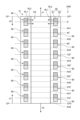
図2は、実施形態による第2デバイス1200を示す模式図である。第2デバイス1200は、柱状の筐体201と、筐体201内に設けられた検出装置1と、を備える。筐体201は、例えば、ヒトの指輪又はリストバンドとして使用されることを想定された樹脂、布又は金属、合金若しくはセラミックスの筒状部材である。第2デバイス1200は、指輪又はリストバンドとすることで、メンバー2200が携帯しやすくなり、システムの適用範囲を広げることができる。以下の説明では、筐体201は、指輪として使用されることを想定された、剛性を有する円柱状の合成樹脂であるものとする。
[Second Device]
2 is a schematic diagram showing a second device 1200 according to an embodiment. The second device 1200 includes a columnar housing 201 and a detection device 1 provided in the housing 201. The housing 201 is, for example, a cylindrical member made of resin, cloth, metal, alloy, or ceramics intended to be used as a human finger ring or wristband. By making the second device 1200 a finger ring or wristband, it becomes easier for the member 2200 to carry it, and the range of application of the system can be expanded. In the following description, the housing 201 is assumed to be a rigid cylindrical synthetic resin intended to be used as a finger ring.

図3は、検出装置1の構成を示す模式図である。図4は、内側に指Fgを収めた状態の第2デバイス1200を筒の一端側から見た場合の構成配置例を示す模式図である。図3及び図4に示す検出装置1は、センサ基板21と、後述する検出領域AAに設けられたフォトダイオードPDを有するセンサ部10(図5参照)と、センサ部10の配置に対応して並ぶ複数の光源60と、を備える。 Figure 3 is a schematic diagram showing the configuration of the detection device 1. Figure 4 is a schematic diagram showing an example of the configuration arrangement of the second device 1200 with a finger Fg placed inside, as viewed from one end of the tube. The detection device 1 shown in Figures 3 and 4 includes a sensor board 21, a sensor unit 10 (see Figure 5) having a photodiode PD provided in a detection area AA described below, and a plurality of light sources 60 arranged in accordance with the arrangement of the sensor unit 10.

検出領域AAは、図4に示すように、第2デバイス1200の筒の内周面に設けられる。検出領域AAは、第2デバイス1200内に収められた構成(例えば、図4に示す指Fg)と当接する。より具体的には、検出領域AAは、図3に示す検出領域AAの一端側の接続部CP1と、検出領域AAの他端側の接続部CP2と、が接続されるよう設けられる。これによって、検出領域AAは、図2に示す筒状の第2デバイス1200の内周面が描く環に沿って、360°連続するように環を形成する。 The detection area AA is provided on the inner peripheral surface of the tube of the second device 1200, as shown in FIG. 4. The detection area AA comes into contact with a structure (e.g., a finger Fg shown in FIG. 4) contained within the second device 1200. More specifically, the detection area AA is provided so that a connection part CP1 on one end side of the detection area AA shown in FIG. 3 is connected to a connection part CP2 on the other end side of the detection area AA. As a result, the detection area AA forms a ring that continues for 360° along the ring described by the inner peripheral surface of the cylindrical second device 1200 shown in FIG. 2.

なお、図2及び図3を参照した説明では、図2に示す接続部CPの位置で、図3に示す接続部CP1と接続部CP2とが当接し、検出領域AAが環を形成するよう設けられているものとする。また、図2に示す接続部CPから、第2デバイス1200の筒の内周面が描く環に沿って一方側に向かう方向を第1方向V1とし、当該環に沿って一方側に向かう方向を第2方向V2とする。また、図2、図3及び図4では、検出領域AAが形成する環の各部分を区別する目的で、環における0°の位置と180°の位置とを定義している。図3及び図4では、さらに、当該0°の位置と180°の位置との間で45°毎に区切られた45°,90°,135°,225°,270°及び315°の位置を示している。 In the description with reference to FIG. 2 and FIG. 3, the connection part CP1 and the connection part CP2 shown in FIG. 3 are abutted at the position of the connection part CP shown in FIG. 2, and the detection area AA is provided to form a ring. Also, the direction from the connection part CP shown in FIG. 2 toward one side along the ring drawn by the inner peripheral surface of the tube of the second device 1200 is defined as the first direction V1, and the direction toward one side along the ring is defined as the second direction V2. Also, in FIG. 2, FIG. 3, and FIG. 4, the 0° position and the 180° position on the ring are defined for the purpose of distinguishing each part of the ring formed by the detection area AA. In FIG. 3 and FIG. 4, the positions of 45°, 90°, 135°, 225°, 270°, and 315° are further shown, which are separated by 45° between the 0° position and the 180° position.

図3では、接続部CPから第2方向V2側に向かって、0°,45°,90°,135°,180°,225°,270°,315°の各位置が一点鎖線で示されている。また、図3では、0°,45°,90°,135°,180°,225°,270°,315°の各位置を中心とした検出領域AAの部分領域AA1,AA2,AA3,AA4,AA5,AA6,AA7,AA8が矩形の破線領域として示されている。部分領域AA1は、0°を中心として、±22.5°の範囲をカバーする領域である。部分領域AA2は、45°を中心として、±22.5°の範囲をカバーする領域である。部分領域AA3は、90°を中心として、±22.5°の範囲をカバーする領域である。部分領域AA4は、135°を中心として、±22.5°の範囲をカバーする領域である。部分領域AA5は、180°を中心として、±22.5°の範囲をカバーする領域である。部分領域AA6は、225°を中心として、±22.5°の範囲をカバーする領域である。部分領域AA7は、270°を中心として、±22.5°の範囲をカバーする領域である。部分領域AA8は、315°を中心として、±22.5°の範囲をカバーする領域である。部分領域AA1,AA2,AA3,AA4,AA5,AA6,AA7,AA8として機能する検出領域AAを構成するセンサ部10(図5参照)の基材として、図4に示すように、センサ基板21が筐体201の内周面に沿って環を描くように設けられる。 In FIG. 3, the positions of 0°, 45°, 90°, 135°, 180°, 225°, 270°, and 315° are indicated by dashed lines from the connection point CP toward the second direction V2. Also, in FIG. 3, partial areas AA1, AA2, AA3, AA4, AA5, AA6, AA7, and AA8 of the detection area AA are indicated as rectangular dashed areas, with each of the positions of 0°, 45°, 90°, 135°, 180°, 225°, 270°, and 315° being the center. Partial area AA1 is an area that covers a range of ±22.5° with 0° as the center. Partial area AA2 is an area that covers a range of ±22.5° with 45° as the center. Partial area AA3 is an area that covers a range of ±22.5° with 90° as the center. Partial area AA4 is an area that covers a range of ±22.5° around 135°. Partial area AA5 is an area that covers a range of ±22.5° around 180°. Partial area AA6 is an area that covers a range of ±22.5° around 225°. Partial area AA7 is an area that covers a range of ±22.5° around 270°. Partial area AA8 is an area that covers a range of ±22.5° around 315°. As shown in FIG. 4, a sensor substrate 21 is provided in a ring shape along the inner periphery of the housing 201 as the base material of the sensor unit 10 (see FIG. 5) that constitutes the detection area AA that functions as partial areas AA1, AA2, AA3, AA4, AA5, AA6, AA7, and AA8.

図3に示すように、部分領域AA1,AA2,AA3,AA4,AA5,AA6,AA7,AA8の各々を挟んで対向するよう、2つの光源60が設けられている。当該2つの光源60の一方は、検出領域AAに対して、第2デバイス1200が形成する筒の一端側に位置する。当該2つの光源60の他方は、検出領域AAに対して、第2デバイス1200が形成する筒の他端側に位置する。従って、図4に示すように、第2デバイス1200を一端側から見た場合、第2デバイス1200の内周面が形成する環に沿って、8つの光源60が並んでいる。当該8つの光源60に含まれる各光源60は、45°毎に配置される。図示しないが、第2デバイス1200を他端側から見た場合にも、同様に、第2デバイス1200の内周面が形成する環に沿って、8つの光源60が並んでいる。 As shown in FIG. 3, two light sources 60 are provided so as to face each other across each of the partial areas AA1, AA2, AA3, AA4, AA5, AA6, AA7, and AA8. One of the two light sources 60 is located at one end of the tube formed by the second device 1200 with respect to the detection area AA. The other of the two light sources 60 is located at the other end of the tube formed by the second device 1200 with respect to the detection area AA. Therefore, as shown in FIG. 4, when the second device 1200 is viewed from one end side, eight light sources 60 are lined up along the ring formed by the inner circumferential surface of the second device 1200. Each light source 60 included in the eight light sources 60 is arranged at 45° intervals. Although not shown, when the second device 1200 is viewed from the other end side, the eight light sources 60 are similarly lined up along the ring formed by the inner circumferential surface of the second device 1200.

各光源60は、第1光源61と、第2光源62とを有する。従って、部分領域AA1,AA2,AA3,AA4,AA5,AA6,AA7,AA8の各々を挟んで対向するよう、2つの第1光源61が設けられている。また、部分領域AA1,AA2,AA3,AA4,AA5,AA6,AA7,AA8の各々を挟んで対向するよう、2つの第2光源62が設けられている。第1光源61は、第2デバイス1200の内周面が形成する環において、第2光源62に対して第1方向V1側に位置する。第2光源62は、第2デバイス1200の内周面が形成する環において、第1光源61に対して第2方向V2側に位置する。図2に示すように、1つの光源60が有する第1光源61と第2光源62との境界線は、0°,45°,90°,135°,180°,225°,270°,315°を示す一点鎖線のいずれかと重なる。なお、図4に示す光XLは、第1光源61から照射されて指Fgを透過した光(例えば、赤外線)である。 Each light source 60 has a first light source 61 and a second light source 62. Therefore, two first light sources 61 are provided so as to face each other across the partial areas AA1, AA2, AA3, AA4, AA5, AA6, AA7, and AA8. In addition, two second light sources 62 are provided so as to face each other across the partial areas AA1, AA2, AA3, AA4, AA5, AA6, AA7, and AA8. The first light source 61 is located on the first direction V1 side relative to the second light source 62 in the ring formed by the inner circumferential surface of the second device 1200. The second light source 62 is located on the second direction V2 side relative to the first light source 61 in the ring formed by the inner circumferential surface of the second device 1200. As shown in FIG. 2, the boundary between the first light source 61 and the second light source 62 of one light source 60 overlaps with any of the dashed lines indicating 0°, 45°, 90°, 135°, 180°, 225°, 270°, and 315°. Note that light XL shown in FIG. 4 is light (e.g., infrared light) that is emitted from the first light source 61 and transmitted through the finger Fg.

以下、検出装置1を構成の一例について説明する。図5は、実施形態1に係る検出装置1を示す平面図である。図5に示すように、検出装置1は、センサ基板21と、センサ部10と、ゲート線駆動回路15と、信号線選択回路16と、検出回路48と、制御回路122と、電源回路123と、第1光源基材51と、第2光源基材52と、第1光源61と、第2光源62と、を有する。 An example of the configuration of the detection device 1 will be described below. FIG. 5 is a plan view showing the detection device 1 according to the first embodiment. As shown in FIG. 5, the detection device 1 has a sensor substrate 21, a sensor unit 10, a gate line driving circuit 15, a signal line selection circuit 16, a detection circuit 48, a control circuit 122, a power supply circuit 123, a first light source substrate 51, a second light source substrate 52, a first light source 61, and a second light source 62.

センサ基板21には、フレキシブルプリント基板71を介して制御基板121が電気的に接続される。フレキシブルプリント基板71には、検出回路48が設けられている。制御基板121には、制御回路122及び電源回路123が設けられている。制御回路122は、例えばFPGA(Field Programmable Gate Array)である。制御回路122は、センサ部10、ゲート線駆動回路15及び信号線選択回路16に制御信号を供給して、センサ部10の検出動作を制御する。また、制御回路122は、第1光源61及び第2光源62に制御信号を供給して、第1光源61及び第2光源62の点灯又は非点灯を制御する。電源回路123は、センサ電源信号VDDSNS(図8参照)等の電圧信号をセンサ部10、ゲート線駆動回路15及び信号線選択回路16に供給する。また、電源回路123は、電源電圧を第1光源61及び第2光源62に供給する。 The control board 121 is electrically connected to the sensor board 21 via the flexible printed circuit board 71. The flexible printed circuit board 71 is provided with a detection circuit 48. The control board 121 is provided with a control circuit 122 and a power supply circuit 123. The control circuit 122 is, for example, an FPGA (Field Programmable Gate Array). The control circuit 122 supplies control signals to the sensor unit 10, the gate line driving circuit 15, and the signal line selection circuit 16 to control the detection operation of the sensor unit 10. The control circuit 122 also supplies control signals to the first light source 61 and the second light source 62 to control the lighting or non-lighting of the first light source 61 and the second light source 62. The power supply circuit 123 supplies voltage signals such as a sensor power supply signal VDDSNS (see FIG. 8) to the sensor unit 10, the gate line driving circuit 15, and the signal line selection circuit 16. The power supply circuit 123 also supplies a power supply voltage to the first light source 61 and the second light source 62.

センサ基板21は、検出領域AAと、周辺領域GAとを有する。検出領域AAは、センサ部10が有する複数のフォトダイオードPDが設けられた領域である。周辺領域GAは、検出領域AAの外周と、センサ基板21の端部との間の領域であり、フォトダイオードPDと重ならない領域である。 The sensor substrate 21 has a detection area AA and a peripheral area GA. The detection area AA is an area in which multiple photodiodes PD of the sensor unit 10 are provided. The peripheral area GA is an area between the outer periphery of the detection area AA and the end of the sensor substrate 21, and is an area that does not overlap with the photodiodes PD.

矩形状の検出領域AAと周辺領域GAとの境界を形成する検出領域AAの四辺のうち一辺と重なる位置が図3に示す接続部CP1になる。また、検出領域AAの四辺のうち検出領域AAを挟んで当該一辺と対向する位置の他の一辺と重なる位置が図3に示す接続部CP2になる。 The position where one of the four sides of the rectangular detection area AA that forms the boundary between the detection area AA and the surrounding area GA overlaps becomes the connection part CP1 shown in FIG. 3. Also, the position where the other of the four sides of the detection area AA overlaps with the other side facing the one side across the detection area AA becomes the connection part CP2 shown in FIG. 3.

ゲート線駆動回路15及び信号線選択回路16は、周辺領域GAに設けられる。具体的には、ゲート線駆動回路15は、周辺領域GAのうち第2方向Dyに沿って延在する領域に設けられる。信号線選択回路16は、周辺領域GAのうち第1方向Dxに沿って延在する領域に設けられ、センサ部10と検出回路48との間に設けられる。 The gate line driving circuit 15 and the signal line selection circuit 16 are provided in the peripheral area GA. Specifically, the gate line driving circuit 15 is provided in a region of the peripheral area GA that extends along the second direction Dy. The signal line selection circuit 16 is provided in a region of the peripheral area GA that extends along the first direction Dx, and is provided between the sensor unit 10 and the detection circuit 48.

なお、第1方向Dxは、センサ基板21と平行な面内の一方向である。第2方向Dyは、センサ基板21と平行な面内の一方向であり、第1方向Dxと直交する方向である。なお、第2方向Dyは、第1方向Dxと直交しないで交差してもよい。また、第3方向Dzは、第1方向Dx及び第2方向Dyと直交する方向であり、センサ基板21の法線方向である。 The first direction Dx is a direction in a plane parallel to the sensor substrate 21. The second direction Dy is a direction in a plane parallel to the sensor substrate 21, and is a direction perpendicular to the first direction Dx. The second direction Dy may intersect the first direction Dx without being perpendicular to it. The third direction Dz is a direction perpendicular to the first direction Dx and the second direction Dy, and is a normal direction of the sensor substrate 21.

複数の第1光源61は、第1光源基材51に設けられ、第2方向Dyに沿って配列される。複数の第2光源62は、第2光源基材52に設けられ、第2方向Dyに沿って配列される。第1光源基材51及び第2光源基材52は、それぞれ、制御基板121に設けられた端子部124、125を介して、制御回路122及び電源回路123と電気的に接続される。 The multiple first light sources 61 are provided on the first light source substrate 51 and are arranged along the second direction Dy. The multiple second light sources 62 are provided on the second light source substrate 52 and are arranged along the second direction Dy. The first light source substrate 51 and the second light source substrate 52 are electrically connected to the control circuit 122 and the power supply circuit 123 via terminal portions 124 and 125 provided on the control board 121, respectively.

複数の第1光源61及び複数の第2光源62は、例えば、無機LED(Light Emitting Diode)や、有機EL(OLED:Organic Light Emitting Diode)等が用いられる。複数の第1光源61及び複数の第2光源62は、それぞれ異なる波長の第1の光及び第2の光を出射する。本実施形態では、第1光源61は、波長が880nmの赤外光を照射する。第2光源62は、波長が665nmの赤色光を出射する。また、検出時、第1光源111と第2光源112は、交互に点灯する。よって、フォトダイオードPDは、赤外光と赤色光の反射光L2を交互に受光する。 The first light sources 61 and the second light sources 62 are, for example, inorganic light emitting diodes (LEDs) or organic light emitting diodes (OLEDs). The first light sources 61 and the second light sources 62 emit first light and second light of different wavelengths, respectively. In this embodiment, the first light source 61 emits infrared light with a wavelength of 880 nm. The second light source 62 emits red light with a wavelength of 665 nm. During detection, the first light source 111 and the second light source 112 are alternately turned on. Thus, the photodiode PD alternately receives the reflected light L2 of infrared light and red light.

赤外光の反射光は、血管パターンを検出するための情報を含む。血液に含まれている赤血球は、ヘモグロビンを有する。第1光源111から照射される赤外光は、ヘモグロビンにより吸光され易い。言い換えると、ヘモグロビンよる赤外光の吸光係数は、体の内部の他の部分よりも吸光係数が高い。よって、複数のフォトダイオードPDの受光量を読み込み、赤外光の反射光L2の受光量が相対的に少ない箇所を特定することで、静脈などの血管パターンを検出できる。 The reflected infrared light contains information for detecting vascular patterns. Red blood cells contained in blood contain hemoglobin. The infrared light irradiated from the first light source 111 is easily absorbed by hemoglobin. In other words, the absorption coefficient of infrared light by hemoglobin is higher than that of other parts inside the body. Therefore, by reading the amount of light received by multiple photodiodes PD and identifying locations where the amount of reflected infrared light L2 received is relatively small, vascular patterns such as veins can be detected.

また、赤外光と赤色光の反射光は、血液中の酸素飽和度(以下、血中酸素飽和度(SpO)と称する)を測定するための情報を含む。なお、血中酸素飽和度(SpO)は、血液中のヘモグロビンの全てに酸素が結合したと仮定した場合の総酸素量に対し、実際にヘモグロビンに結合している酸素量の比である。 The reflected infrared and red light also contains information for measuring the oxygen saturation in the blood (hereinafter referred to as blood oxygen saturation ( SpO2 )). Note that blood oxygen saturation ( SpO2 ) is the ratio of the amount of oxygen actually bound to hemoglobin to the total amount of oxygen that would be present if all of the hemoglobin in the blood were bound to oxygen.

赤外光は、ヘモグロビンにより吸光され易い。ヘモグロビンの量が多くなると、吸光される赤外光の光量も多くなり、フォトダイオードPDの受光量も低減する。つまり、赤外光の反射光L2の受光量により、ヘモグロビンの全体量が把握される。 Infrared light is easily absorbed by hemoglobin. As the amount of hemoglobin increases, the amount of infrared light absorbed also increases, and the amount of light received by the photodiode PD also decreases. In other words, the total amount of hemoglobin can be determined from the amount of reflected infrared light L2 received.

一方で、ヘモグロビンは、酸素と結合していない状態で赤黒い色であり、酸素と結合すると鮮やかな赤色となる。このため、ヘモグロビンは、酸素と結合した状態と、酸素と結合していない状態とで、赤色光を吸収する吸光係数が異なる。よって、血液中に酸素と結合した状態のヘモグロビンが多いと、赤色光の反射光が多くなる。他方で、血液中に酸素と結合していない状態のヘモグロビンが多いと、赤色光の反射光が少なくなる。以上から、赤色光の反射光の受光量に基づき、酸素と結合した状態のヘモグロビンの量が相対的に把握される。 On the other hand, hemoglobin is dark red when not bound to oxygen, and turns bright red when bound to oxygen. For this reason, hemoglobin has a different absorption coefficient for absorbing red light when bound to oxygen and when not bound to oxygen. Therefore, if there is a lot of hemoglobin bound to oxygen in the blood, there will be more reflected red light. On the other hand, if there is a lot of hemoglobin not bound to oxygen in the blood, there will be less reflected red light. From the above, the amount of hemoglobin bound to oxygen can be relatively determined based on the amount of reflected red light received.

そして、把握されたヘモグロビンの全体量と、酸素と結合した状態のヘモグロビンの量と、を対比することで、実際にヘモグロビンに結合している酸素量の比(血中酸素飽和度(SpO))が把握される。これにより、検出装置1は、第1光源61及び複数の第2光源62を有しているので、第1の光に基づいた検出と、第2の光に基づいた検出とを行うことで、指Fg等の内部の生体に関する情報を検出することができる。検出装置1は、検出した血中酸素飽和度、脈拍等を含む生体に関する情報を、フレキシブルプリント基板71を介して制御基板121に供給できる。 Then, by comparing the total amount of hemoglobin thus determined with the amount of hemoglobin bound to oxygen, the ratio of the amount of oxygen actually bound to hemoglobin (blood oxygen saturation (SpO2 ) ) is determined. As a result, since the detection device 1 has a first light source 61 and a plurality of second light sources 62, it is possible to detect information about an internal living body such as a finger Fg by performing detection based on the first light and detection based on the second light. The detection device 1 can supply information about the living body including the detected blood oxygen saturation, pulse rate, etc. to the control board 121 via the flexible printed board 71.

なお、本開示において、第1光源61と第2光源62から出射される光の波長は上記に限定されない。第1光源61は、波長が800以上1000nm未満の赤外光を出射できればよい。第2光源62は、波長が600nm以上800nm未満の赤色光を出射できればよい。 In this disclosure, the wavelengths of the light emitted from the first light source 61 and the second light source 62 are not limited to those described above. The first light source 61 is required to emit infrared light having a wavelength of 800 to less than 1000 nm. The second light source 62 is required to emit red light having a wavelength of 600 to less than 800 nm.

なお、図5に示す第1光源61及び第2光源62の配置は、あくまで一例であり適宜変更することができる。例えば、第1光源基材51及び第2光源基材52のそれぞれに、複数の第1光源61及び複数の第2光源62が配置されていてもよい。この場合、複数の第1光源61を含むグループと、複数の第2光源62を含むグループとが、第2方向Dyに並んで配置されていてもよいし、第1光源61と第2光源62とが交互に第2方向Dyに配置されていてもよい。また、第1光源61及び第2光源62が設けられる光源基材は1つ又は3つ以上であってもよい。 The arrangement of the first light source 61 and the second light source 62 shown in FIG. 5 is merely an example and can be changed as appropriate. For example, a plurality of first light sources 61 and a plurality of second light sources 62 may be arranged on each of the first light source substrate 51 and the second light source substrate 52. In this case, a group including a plurality of first light sources 61 and a group including a plurality of second light sources 62 may be arranged side by side in the second direction Dy, or the first light sources 61 and the second light sources 62 may be arranged alternately in the second direction Dy. In addition, the number of light source substrates on which the first light source 61 and the second light source 62 are provided may be one or three or more.

図6は、実施形態に係る検出装置1の構成例を示すブロック図である。図6に示すように、検出装置1は、さらに検出制御部11と検出部40と、有する。検出制御部11の機能の一部又は全部は、制御回路122に含まれる。また、検出部40のうち、検出回路48以外の機能の一部又は全部は、制御回路122に含まれる。 Fig. 6 is a block diagram showing an example of the configuration of the detection device 1 according to the embodiment. As shown in Fig. 6, the detection device 1 further includes a detection control unit 11 and a detection unit 40. Some or all of the functions of the detection control unit 11 are included in the control circuit 122. In addition, some or all of the functions of the detection unit 40 other than the detection circuit 48 are included in the control circuit 122.

センサ部10は、光電変換素子であるフォトダイオードPDを有する光センサである。センサ部10が有するフォトダイオードPDは、照射される光に応じた電気信号を、検出信号Vdetとして信号線選択回路16に出力する。また、センサ部10は、ゲート線駆動回路15から供給されるゲート駆動信号Vgclにしたがって検出を行う。 The sensor unit 10 is an optical sensor having a photodiode PD, which is a photoelectric conversion element. The photodiode PD of the sensor unit 10 outputs an electrical signal corresponding to the irradiated light to the signal line selection circuit 16 as a detection signal Vdet. The sensor unit 10 also performs detection according to a gate drive signal Vgcl supplied from the gate line drive circuit 15.

検出制御部11は、ゲート線駆動回路15、信号線選択回路16及び検出部40にそれぞれ制御信号を供給し、これらの動作を制御する回路である。検出制御部11は、スタート信号STV、クロック信号CK、リセット信号RST1等の各種制御信号をゲート線駆動回路15に供給する。また、検出制御部11は、選択信号ASW等の各種制御信号を信号線選択回路16に供給する。また、検出制御部11は、各種制御信号を第1光源61及び第2光源62に供給して、それぞれの点灯及び非点灯を制御する。 The detection control unit 11 is a circuit that supplies control signals to the gate line driving circuit 15, the signal line selection circuit 16, and the detection unit 40, respectively, and controls their operation. The detection control unit 11 supplies various control signals, such as a start signal STV, a clock signal CK, and a reset signal RST1, to the gate line driving circuit 15. The detection control unit 11 also supplies various control signals, such as a selection signal ASW, to the signal line selection circuit 16. The detection control unit 11 also supplies various control signals to the first light source 61 and the second light source 62, and controls the lighting and non-lighting of each.

ゲート線駆動回路15は、各種制御信号に基づいて複数のゲート線GCL(図7参照)を駆動する回路である。ゲート線駆動回路15は、複数のゲート線GCLを順次又は同時に選択し、選択されたゲート線GCLにゲート駆動信号Vgclを供給する。これにより、ゲート線駆動回路15は、ゲート線GCLに接続された複数のフォトダイオードPDを選択する。 The gate line driving circuit 15 is a circuit that drives multiple gate lines GCL (see FIG. 7) based on various control signals. The gate line driving circuit 15 selects multiple gate lines GCL sequentially or simultaneously, and supplies a gate driving signal Vgcl to the selected gate lines GCL. In this way, the gate line driving circuit 15 selects multiple photodiodes PD connected to the gate lines GCL.

信号線選択回路16は、複数の信号線SGL(図7参照)を順次又は同時に選択するスイッチ回路である。信号線選択回路16は、例えばマルチプレクサである。信号線選択回路16は、検出制御部11から供給される選択信号ASWに基づいて、選択された信号線SGLと検出回路48とを接続する。これにより、信号線選択回路16は、フォトダイオードPDの検出信号Vdetを検出部40に出力する。 The signal line selection circuit 16 is a switch circuit that sequentially or simultaneously selects multiple signal lines SGL (see FIG. 7). The signal line selection circuit 16 is, for example, a multiplexer. The signal line selection circuit 16 connects the selected signal line SGL to the detection circuit 48 based on the selection signal ASW supplied from the detection control unit 11. As a result, the signal line selection circuit 16 outputs the detection signal Vdet of the photodiode PD to the detection unit 40.

検出部40は、検出回路48と、信号処理部44と、座標抽出部45と、記憶部46と、検出タイミング制御部47と、画像処理部49と、を備える。検出タイミング制御部47は、検出制御部11から供給される制御信号に基づいて、検出回路48と、信号処理部44と、座標抽出部45と、画像処理部49と、が同期して動作するように制御する。 The detection unit 40 includes a detection circuit 48, a signal processing unit 44, a coordinate extraction unit 45, a storage unit 46, a detection timing control unit 47, and an image processing unit 49. The detection timing control unit 47 controls the detection circuit 48, the signal processing unit 44, the coordinate extraction unit 45, and the image processing unit 49 to operate in synchronization based on a control signal supplied from the detection control unit 11.

検出回路48は、例えばアナログフロントエンド回路(AFE:Analog Front End)である。検出回路48は、少なくとも検出信号増幅部42及びA/D変換部43の機能を有する信号処理回路である。検出信号増幅部42は、検出信号Vdetを増幅する。A/D変換部43は、検出信号増幅部42から出力されるアナログ信号をデジタル信号に変換する。 The detection circuit 48 is, for example, an analog front-end circuit (AFE). The detection circuit 48 is a signal processing circuit having at least the functions of a detection signal amplifier 42 and an A/D converter 43. The detection signal amplifier 42 amplifies the detection signal Vdet. The A/D converter 43 converts the analog signal output from the detection signal amplifier 42 into a digital signal.

信号処理部44は、検出回路48の出力信号に基づいて、センサ部10に入力された所定の物理量を検出する論理回路である。信号処理部44は、指Fgが検出面に接触又は近接した場合に、検出回路48からの信号に基づいて指Fgや掌の表面の凹凸を検出できる。また、信号処理部44は、検出回路48からの信号に基づいて生体に関する情報を検出できる。生体に関する情報は、例えば、指Fgの脈拍、血中酸素飽和度等である。 The signal processing unit 44 is a logic circuit that detects a predetermined physical quantity input to the sensor unit 10 based on the output signal of the detection circuit 48. When the finger Fg is in contact with or in close proximity to the detection surface, the signal processing unit 44 can detect unevenness on the surface of the finger Fg or the palm based on the signal from the detection circuit 48. The signal processing unit 44 can also detect information about the living body based on the signal from the detection circuit 48. The information about the living body is, for example, the pulse rate of the finger Fg, blood oxygen saturation, etc.

また、信号処理部44は、複数のフォトダイオードPDにより同時に検出された検出信号Vdet(生体に関する情報)を取得し、これらを平均化する処理を実行してもよい。この場合、検出部40は、ノイズや、指Fg等の被検出体とセンサ部10との相対的な位置ずれに起因する測定誤差を抑制して、安定した検出が可能となる。 The signal processing unit 44 may also acquire detection signals Vdet (information about the living body) simultaneously detected by multiple photodiodes PD and perform a process of averaging these. In this case, the detection unit 40 can suppress measurement errors caused by noise and relative positional deviation between the detection object such as a finger Fg and the sensor unit 10, enabling stable detection.

記憶部46は、信号処理部44で演算された信号を一時的に保存する。記憶部46は、例えばRAM(Random Access Memory)、レジスタ回路等であってもよい。 The memory unit 46 temporarily stores the signal calculated by the signal processing unit 44. The memory unit 46 may be, for example, a RAM (Random Access Memory), a register circuit, etc.

座標抽出部45は、信号処理部44において指の接触又は近接が検出されたときに、指等の表面の凹凸の検出座標を求める論理回路である。また、座標抽出部45は、指Fgや掌の血管の検出座標を求める論理回路である。画像処理部49は、センサ部10の各フォトダイオードPDから出力される検出信号Vdetを組み合わせて、指Fg等の表面の凹凸の形状を示す二次元情報及び指Fgや掌の血管の形状を示す二次元情報を生成する。なお、座標抽出部45は、検出座標を算出せずにセンサ出力Voとして検出信号Vdetを出力してもよい。また、座標抽出部45及び画像処理部49は、検出部40に含まれていない場合であってもよい。 The coordinate extraction unit 45 is a logic circuit that determines the detection coordinates of the unevenness of the surface of the finger, etc., when the signal processing unit 44 detects contact or proximity of a finger. The coordinate extraction unit 45 is also a logic circuit that determines the detection coordinates of the blood vessels of the finger Fg or the palm. The image processing unit 49 combines the detection signals Vdet output from each photodiode PD of the sensor unit 10 to generate two-dimensional information indicating the shape of the unevenness of the surface of the finger Fg, etc., and two-dimensional information indicating the shape of the blood vessels of the finger Fg or the palm. The coordinate extraction unit 45 may output the detection signal Vdet as the sensor output Vo without calculating the detection coordinates. The coordinate extraction unit 45 and the image processing unit 49 may not be included in the detection unit 40.

次に、検出装置1の回路構成例について説明する。図7は、検出装置1を示す回路図である。図8は、複数の部分検出領域を示す回路図である。なお、図8では、検出回路48の回路構成も併せて示している。 Next, an example of the circuit configuration of the detection device 1 will be described. FIG. 7 is a circuit diagram showing the detection device 1. FIG. 8 is a circuit diagram showing a plurality of partial detection areas. Note that FIG. 8 also shows the circuit configuration of the detection circuit 48.

図7に示すように、センサ部10は、マトリクス状に配列された複数の部分検出領域PAAを有する。複数の部分検出領域PAAには、それぞれフォトダイオードPDが設けられている。 As shown in FIG. 7, the sensor unit 10 has a plurality of partial detection areas PAA arranged in a matrix. Each of the partial detection areas PAA is provided with a photodiode PD.

ゲート線GCLは、第1方向Dxに延在し、第1方向Dxに配列された複数の部分検出領域PAAと接続される。また、複数のゲート線GCL(1)、GCL(2)、…、GCL(8)は、第2方向Dyに配列され、それぞれゲート線駆動回路15に接続される。なお、以下の説明において、複数のゲート線GCL(1)、GCL(2)、…、GCL(8)を区別して説明する必要がない場合には、単にゲート線GCLと表す。また、図7では説明を分かりやすくするために、8本のゲート線GCLを示しているが、あくまで一例であり、ゲート線GCLは、M本(Mは8以上、例えばM=256)配列されていてもよい。 The gate line GCL extends in the first direction Dx and is connected to a plurality of partial detection areas PAA arranged in the first direction Dx. The plurality of gate lines GCL(1), GCL(2), ..., GCL(8) are arranged in the second direction Dy and are each connected to the gate line driving circuit 15. In the following description, when it is not necessary to distinguish between the plurality of gate lines GCL(1), GCL(2), ..., GCL(8), they are simply referred to as gate lines GCL. In addition, in FIG. 7, eight gate lines GCL are shown for ease of explanation, but this is merely an example, and M gate lines GCL (M is 8 or more, for example, M=256) may be arranged.

信号線SGLは、第2方向Dyに延在し、第2方向Dyに配列された複数の部分検出領域PAAのフォトダイオードPDに接続される。また、複数の信号線SGL(1)、SGL(2)、…、SGL(12)は、第1方向Dxに配列されて、それぞれ信号線選択回路16及びリセット回路17に接続される。なお、以下の説明において、複数の信号線SGL(1)、SGL(2)、…、SGL(12)を区別して説明する必要がない場合には、単に信号線SGLと表す。 The signal line SGL extends in the second direction Dy and is connected to the photodiodes PD of the multiple partial detection areas PAA arranged in the second direction Dy. The multiple signal lines SGL(1), SGL(2), ..., SGL(12) are arranged in the first direction Dx and are each connected to the signal line selection circuit 16 and the reset circuit 17. In the following description, when it is not necessary to distinguish between the multiple signal lines SGL(1), SGL(2), ..., SGL(12), they will simply be referred to as signal lines SGL.

また、説明を分かりやすくするために、12本の信号線SGLを示しているが、あくまで一例であり、信号線SGLは、N本(Nは12以上、例えばN=252)配列されていてもよい。また、図7では、信号線選択回路16とリセット回路17との間にセンサ部10が設けられている。これに限定されず、信号線選択回路16とリセット回路17とは、信号線SGLの同じ方向の端部にそれぞれ接続されていてもよい。 For ease of understanding, 12 signal lines SGL are shown, but this is merely an example, and N signal lines SGL (N is 12 or more, for example, N=252) may be arranged. In addition, in FIG. 7, a sensor unit 10 is provided between the signal line selection circuit 16 and the reset circuit 17. However, this is not limiting, and the signal line selection circuit 16 and the reset circuit 17 may each be connected to the ends of the signal lines SGL in the same direction.

ゲート線駆動回路15は、スタート信号STV、クロック信号CK、リセット信号RST1等の各種制御信号を、制御回路122(図5参照)から受け取る。ゲート線駆動回路15は、各種制御信号に基づいて、複数のゲート線GCL(1)、GCL(2)、…、GCL(8)を時分割的に順次選択する。ゲート線駆動回路15は、選択されたゲート線GCLにゲート駆動信号Vgclを供給する。これにより、ゲート線GCLに接続された複数の第1スイッチング素子Trにゲート駆動信号Vgclが供給され、第1方向Dxに配列された複数の部分検出領域PAAが、検出対象として選択される。 The gate line driving circuit 15 receives various control signals, such as a start signal STV, a clock signal CK, and a reset signal RST1, from the control circuit 122 (see FIG. 5). Based on the various control signals, the gate line driving circuit 15 sequentially selects multiple gate lines GCL(1), GCL(2), ..., GCL(8) in a time-division manner. The gate line driving circuit 15 supplies a gate driving signal Vgcl to the selected gate line GCL. As a result, the gate driving signal Vgcl is supplied to multiple first switching elements Tr connected to the gate line GCL, and multiple partial detection areas PAA arranged in the first direction Dx are selected as detection targets.

なお、ゲート線駆動回路15は、指紋の検出及び異なる複数の生体に関する情報(例えば、脈拍、血中酸素飽和度等)のそれぞれの検出モードごとに、異なる駆動を実行してもよい。例えば、ゲート線駆動回路15は、複数のゲート線GCLを束ねて駆動してもよい。 The gate line driving circuit 15 may perform different driving for each detection mode of fingerprint detection and multiple different pieces of biometric information (e.g., pulse, blood oxygen saturation, etc.). For example, the gate line driving circuit 15 may drive multiple gate lines GCL in a bundle.

具体的には、ゲート線駆動回路15は、制御信号に基づいて、ゲート線GCL(1)、GCL(2)、…、GCL(8)のうち、所定数のゲート線GCLを同時に選択する。例えば、ゲート線駆動回路15は、6本のゲート線GCL(1)からゲート線GCL(6)を同時に選択し、ゲート駆動信号Vgclを供給する。ゲート線駆動回路15は、選択された6本のゲート線GCLを介して、複数の第1スイッチング素子Trにゲート駆動信号Vgclを供給する。これにより、第1方向Dx及び第2方向Dyに配列された複数の部分検出領域PAAを含む検出領域グループPAG1、PAG2が、それぞれ検出対象として選択される。ゲート線駆動回路15は、所定数のゲート線GCLを束ねて駆動し、所定数のゲート線GCLごとに順次ゲート駆動信号Vgclを供給する。 Specifically, the gate line driving circuit 15 simultaneously selects a predetermined number of gate lines GCL from the gate lines GCL(1), GCL(2), ..., GCL(8) based on the control signal. For example, the gate line driving circuit 15 simultaneously selects six gate lines GCL(1) to GCL(6) and supplies the gate driving signal Vgcl. The gate line driving circuit 15 supplies the gate driving signal Vgcl to the first switching elements Tr via the six selected gate lines GCL. As a result, the detection area groups PAG1 and PAG2 including the partial detection areas PAA arranged in the first direction Dx and the second direction Dy are each selected as detection targets. The gate line driving circuit 15 drives a predetermined number of gate lines GCL in a bundle and sequentially supplies the gate driving signal Vgcl to each of the predetermined number of gate lines GCL.

信号線選択回路16は、複数の選択信号線Lselと、複数の出力信号線Loutと、第3スイッチング素子TrSと、を有する。複数の第3スイッチング素子TrSは、それぞれ複数の信号線SGLに対応して設けられている。6本の信号線SGL(1)、SGL(2)、…、SGL(6)は、共通の出力信号線Lout1に接続される。6本の信号線SGL(7)、SGL(8)、…、SGL(12)は、共通の出力信号線Lout2に接続される。出力信号線Lout1、Lout2は、それぞれ検出回路48に接続される。 The signal line selection circuit 16 has a plurality of selection signal lines Lsel, a plurality of output signal lines Lout, and a third switching element TrS. The plurality of third switching elements TrS are provided corresponding to the plurality of signal lines SGL, respectively. The six signal lines SGL(1), SGL(2), ..., SGL(6) are connected to a common output signal line Lout1. The six signal lines SGL(7), SGL(8), ..., SGL(12) are connected to a common output signal line Lout2. The output signal lines Lout1, Lout2 are each connected to a detection circuit 48.

ここで、信号線SGL(1)、SGL(2)、…、SGL(6)を第1信号線ブロックとし、信号線SGL(7)、SGL(8)、…、SGL(12)を第2信号線ブロックとする。複数の選択信号線Lselは、1つの信号線ブロックに含まれる第3スイッチング素子TrSのゲートにそれぞれ接続される。また、1本の選択信号線Lselは、複数の信号線ブロックの第3スイッチング素子TrSのゲートに接続される。 Here, the signal lines SGL(1), SGL(2), ..., SGL(6) are the first signal line block, and the signal lines SGL(7), SGL(8), ..., SGL(12) are the second signal line block. The multiple selection signal lines Lsel are each connected to the gate of the third switching element TrS included in one signal line block. In addition, one selection signal line Lsel is connected to the gate of the third switching element TrS of the multiple signal line blocks.

具体的には、選択信号線Lsel1、Lsel2、…、Lsel6は、それぞれ信号線SGL(1)、SGL(2)、…、SGL(6)に対応する第3スイッチング素子TrSと接続される。また、選択信号線Lsel1は、信号線SGL(1)に対応する第3スイッチング素子TrSと、信号線SGL(7)に対応する第3スイッチング素子TrSと、に接続される。選択信号線Lsel2は、信号線SGL(2)に対応する第3スイッチング素子TrSと、信号線SGL(8)に対応する第3スイッチング素子TrSと、に接続される。 Specifically, the selection signal lines Lsel1, Lsel2, ..., Lsel6 are connected to the third switching elements TrS corresponding to the signal lines SGL(1), SGL(2), ..., SGL(6), respectively. The selection signal line Lsel1 is connected to the third switching element TrS corresponding to the signal line SGL(1) and the third switching element TrS corresponding to the signal line SGL(7). The selection signal line Lsel2 is connected to the third switching element TrS corresponding to the signal line SGL(2) and the third switching element TrS corresponding to the signal line SGL(8).

制御回路122(図5参照)は、選択信号ASWを順次選択信号線Lselに供給する。これにより、信号線選択回路16は、第3スイッチング素子TrSの動作により、1つの信号線ブロックにおいて信号線SGLを時分割的に順次選択する。また、信号線選択回路16は、複数の信号線ブロックでそれぞれ1本ずつ信号線SGLを選択する。このような構成により、検出装置1は、検出回路48を含むIC(Integrated Circuit)の数、又はICの端子数を少なくすることができる。 The control circuit 122 (see FIG. 5) sequentially supplies the selection signal ASW to the selection signal line Lsel. As a result, the signal line selection circuit 16 sequentially selects the signal lines SGL in one signal line block in a time-division manner by the operation of the third switching element TrS. The signal line selection circuit 16 also selects one signal line SGL in each of the multiple signal line blocks. With this configuration, the detection device 1 can reduce the number of ICs (Integrated Circuits) including the detection circuit 48, or the number of IC terminals.

なお、信号線選択回路16は、複数の信号線SGLを束ねて検出回路48に接続してもよい。具体的には、制御回路122(図5参照)は、選択信号ASWを同時に選択信号線Lselに供給する。これにより、信号線選択回路16は、第3スイッチング素子TrSの動作により、1つの信号線ブロックにおいて複数の信号線SGL(例えば6本の信号線SGL)を選択し、複数の信号線SGLと検出回路48とを接続する。これにより、検出領域グループPAG1、PAG2で検出された信号が検出回路48に出力される。この場合、検出領域グループPAG1、PAG2に含まれる複数の部分検出領域PAA(フォトダイオードPD)からの信号が統合されて検出回路48に出力される。 The signal line selection circuit 16 may bundle multiple signal lines SGL and connect them to the detection circuit 48. Specifically, the control circuit 122 (see FIG. 5) simultaneously supplies the selection signal ASW to the selection signal line Lsel. As a result, the signal line selection circuit 16 selects multiple signal lines SGL (e.g., six signal lines SGL) in one signal line block by the operation of the third switching element TrS, and connects the multiple signal lines SGL to the detection circuit 48. As a result, the signals detected in the detection area groups PAG1 and PAG2 are output to the detection circuit 48. In this case, signals from multiple partial detection areas PAA (photodiodes PD) included in the detection area groups PAG1 and PAG2 are integrated and output to the detection circuit 48.

ゲート線駆動回路15及び信号線選択回路16の動作により、検出領域グループPAG1、PAG2ごとに検出を行うことで、1回の検出で得られる検出信号Vdetの強度が向上するのでセンサ感度を向上させることができる。また、検出に要する時間を短縮することができる。このため、検出装置1は、検出を短時間で繰り返し実行することができるので、S/N比を向上させることができ、又、脈波等の生体に関する情報の時間的な変化を精度よく検出することができる。 By performing detection for each detection area group PAG1, PAG2 through the operation of the gate line driving circuit 15 and the signal line selection circuit 16, the strength of the detection signal Vdet obtained in one detection is improved, thereby improving the sensor sensitivity. In addition, the time required for detection can be shortened. Therefore, the detection device 1 can repeatedly perform detection in a short period of time, thereby improving the S/N ratio and enabling accurate detection of temporal changes in information about the living body, such as pulse waves.

図7に示すように、リセット回路17は、基準信号線Lvr、リセット信号線Lrst及び第4スイッチング素子TrRを有する。第4スイッチング素子TrRは、複数の信号線SGLに対応して設けられている。基準信号線Lvrは、複数の第4スイッチング素子TrRのソース又はドレインの一方に接続される。リセット信号線Lrstは、複数の第4スイッチング素子TrRのゲートに接続される。 As shown in FIG. 7, the reset circuit 17 has a reference signal line Lvr, a reset signal line Lrst, and a fourth switching element TrR. The fourth switching element TrR is provided corresponding to the multiple signal lines SGL. The reference signal line Lvr is connected to one of the sources or drains of the multiple fourth switching elements TrR. The reset signal line Lrst is connected to the gates of the multiple fourth switching elements TrR.

制御回路122は、リセット信号RST2をリセット信号線Lrstに供給する。これにより、複数の第4スイッチング素子TrRがオンになり、複数の信号線SGLは基準信号線Lvrと電気的に接続される。電源回路123は、基準信号COMを基準信号線Lvrに供給する。これにより、複数の部分検出領域PAAに含まれる容量素子Ca(図8参照)に基準信号COMが供給される。 The control circuit 122 supplies a reset signal RST2 to the reset signal line Lrst. This turns on the multiple fourth switching elements TrR, and the multiple signal lines SGL are electrically connected to the reference signal line Lvr. The power supply circuit 123 supplies a reference signal COM to the reference signal line Lvr. This causes the reference signal COM to be supplied to the capacitive elements Ca (see FIG. 8) included in the multiple partial detection areas PAA.

図8に示すように、部分検出領域PAAは、フォトダイオードPDと、容量素子Caと、第1スイッチング素子Trとを含む。図8では、複数のゲート線GCLのうち、第2方向Dyに並ぶ2つのゲート線GCL(m)、GCL(m+1)を示す。また、複数の信号線SGLのうち、第1方向Dxに並ぶ2つの信号線SGL(n)、SGL(n+1)を示す。部分検出領域PAAは、ゲート線GCLと信号線SGLとで囲まれた領域である。第1スイッチング素子Trは、フォトダイオードPDに対応して設けられる。第1スイッチング素子Trは、薄膜トランジスタにより構成されるものであり、この例では、nチャネルのMOS(Metal Oxide Semiconductor)型のTFT(Thin Film Transistor)で構成されている。 As shown in FIG. 8, the partial detection area PAA includes a photodiode PD, a capacitance element Ca, and a first switching element Tr. In FIG. 8, two gate lines GCL(m) and GCL(m+1) arranged in the second direction Dy among the multiple gate lines GCL are shown. Also, two signal lines SGL(n) and SGL(n+1) arranged in the first direction Dx among the multiple signal lines SGL are shown. The partial detection area PAA is an area surrounded by the gate lines GCL and the signal lines SGL. The first switching element Tr is provided corresponding to the photodiode PD. The first switching element Tr is composed of a thin film transistor, and in this example, is composed of an n-channel MOS (Metal Oxide Semiconductor) type TFT (Thin Film Transistor).

第1方向Dxに並ぶ複数の部分検出領域PAAに属する第1スイッチング素子Trのゲートは、ゲート線GCLに接続される。第2方向Dyに並ぶ複数の部分検出領域PAAに属する第1スイッチング素子Trのソースは、信号線SGLに接続される。第1スイッチング素子Trのドレインは、フォトダイオードPDのカソード及び容量素子Caに接続される。 The gates of the first switching elements Tr belonging to the multiple partial detection areas PAA aligned in the first direction Dx are connected to the gate line GCL. The sources of the first switching elements Tr belonging to the multiple partial detection areas PAA aligned in the second direction Dy are connected to the signal line SGL. The drains of the first switching elements Tr are connected to the cathodes of the photodiodes PD and the capacitance elements Ca.

フォトダイオードPDのアノードには、電源回路123からセンサ電源信号VDDSNSが供給される。また、信号線SGL及び容量素子Caには、電源回路123から、信号線SGL及び容量素子Caの初期電位となる基準信号COMが供給される。 The anode of the photodiode PD is supplied with a sensor power supply signal VDDSNS from the power supply circuit 123. In addition, the signal line SGL and the capacitance element Ca are supplied with a reference signal COM, which is the initial potential of the signal line SGL and the capacitance element Ca, from the power supply circuit 123.

部分検出領域PAAに光が照射されると、フォトダイオードPDには光量に応じた電流が流れ、これにより容量素子Caに電荷が蓄積される。第1スイッチング素子Trがオンになると、容量素子Caに蓄積された電荷に応じて、信号線SGLに電流が流れる。信号線SGLは、信号線選択回路16の第3スイッチング素子TrSを介して検出回路48に接続される。これにより、検出装置1は、部分検出領域PAAごとに、又は検出領域グループPAG1、PAG2ごとにフォトダイオードPDに照射される光の光量に応じた信号を検出できる。 When light is irradiated onto the partial detection area PAA, a current corresponding to the amount of light flows through the photodiode PD, causing charge to accumulate in the capacitance element Ca. When the first switching element Tr is turned on, a current flows through the signal line SGL according to the charge accumulated in the capacitance element Ca. The signal line SGL is connected to the detection circuit 48 via the third switching element TrS of the signal line selection circuit 16. This allows the detection device 1 to detect a signal corresponding to the amount of light irradiated onto the photodiode PD for each partial detection area PAA or for each detection area group PAG1, PAG2.

検出回路48は、読み出し期間にスイッチSSWがオンになり、信号線SGLと接続される。検出回路48の検出信号増幅部42は、信号線SGLから供給された電流の変動を電圧の変動に変換して増幅する。検出信号増幅部42の非反転入力部(+)には、固定された電位を有する基準電圧Vrefが入力され、反転入力端子(-)には、信号線SGLが接続される。本実施形態では、基準電圧Vrefとして基準信号COMと同じ信号が入力される。また、検出信号増幅部42は、容量素子Cb及びリセットスイッチRSWを有する。リセット期間において、リセットスイッチRSWがオンになり、容量素子Cbの電荷がリセットされる。 During the readout period, the switch SSW of the detection circuit 48 is turned on and connected to the signal line SGL. The detection signal amplifier 42 of the detection circuit 48 converts the fluctuation in current supplied from the signal line SGL into a fluctuation in voltage and amplifies it. A reference voltage Vref having a fixed potential is input to the non-inverting input terminal (+) of the detection signal amplifier 42, and the signal line SGL is connected to the inverting input terminal (-). In this embodiment, a signal that is the same as the reference signal COM is input as the reference voltage Vref. The detection signal amplifier 42 also has a capacitance element Cb and a reset switch RSW. During the reset period, the reset switch RSW is turned on and the charge of the capacitance element Cb is reset.

このような構成により、検出装置1は、複数のフォトダイオードPDを有することで、対象物の血中酸素飽和度、脈拍等の生体に関する情報を検出し、検出した情報を含む生体情報をユニットの外部に供給することができる。 With this configuration, the detection device 1 has multiple photodiodes PD, and can detect information about the subject's biological body, such as blood oxygen saturation and pulse rate, and supply biological information including the detected information to the outside of the unit.

次に、第2デバイス1200の機能構成について説明する。図9は、第2デバイス1200の機能構成の一例を示す構成図である。図9に示すように、第2デバイス1200は、上述した検出装置1と、高度センサ210と、通信部220と、記憶部230と、制御部240と、を備える。制御部240は、検出装置1、高度センサ210、通信部220及び記憶部230と電気的に接続されている。 Next, the functional configuration of the second device 1200 will be described. FIG. 9 is a configuration diagram showing an example of the functional configuration of the second device 1200. As shown in FIG. 9, the second device 1200 includes the above-mentioned detection device 1, an altitude sensor 210, a communication unit 220, a memory unit 230, and a control unit 240. The control unit 240 is electrically connected to the detection device 1, the altitude sensor 210, the communication unit 220, and the memory unit 230.

検出装置1は、メンバー2200の指Fg等の内部の生体に関する生体情報D10を測定し、該生体情報D10を制御部240に供給する。検出装置1は、例えば、所定のタイミングで生体情報D10を測定するごとに、生体情報D10を制御部240に供給する。所定のタイミングは、例えば、設定された周期、間隔、時間等を含む。本実施形態では、検出装置1は、血中酸素飽和度を含む生体情報D10を制御部240に供給することで、血中酸素飽和度センサとして機能している。 The detection device 1 measures biometric information D10 related to the internal living body of the finger Fg, etc. of the member 2200, and supplies the biometric information D10 to the control unit 240. The detection device 1 supplies the biometric information D10 to the control unit 240, for example, each time it measures the biometric information D10 at a predetermined timing. The predetermined timing includes, for example, a set period, interval, time, etc. In this embodiment, the detection device 1 functions as a blood oxygen saturation sensor by supplying the biometric information D10 including blood oxygen saturation to the control unit 240.

高度センサ210は、第2デバイス1200の高度に関する情報を測定する。高度センサ210は、気圧センサ、GPS(全地球測位システム:Global Positioning System)受信機、高度計等を含む。高度センサ210は、第2デバイス1200に作用する周囲の気圧を測定し、該気圧を高度に置き換える機能を有する。高度センサ210は、測定した気圧を変換プログラム、変換テーブル等を用いて高度を算出する。高度センサ210は、GPS受信機が測定した第2デバイス1200の現在位置(緯度経度)の高度(標高)を、地図情報が示す緯度経度と高さとの関係から算出する。地図情報は、例えば、緯度経度と高度(標高)との情報がマッピングされた情報を含む。高度センサ210は、測定した高度、気圧等が識別可能な高度情報D20を制御部240に供給する。本実施形態では、高度センサ210は、検出装置1に含まれない構成について説明するが、検出装置1に含まれる構成としてもよい。また、リーダー2100が複数のメンバー2200と行動を共にすることを前提にする場合、第2デバイス1200は、高度センサ210を備えない構成とし、第1デバイス1100が自機の高度をメンバー2200の高度としてもよい。 The altitude sensor 210 measures information about the altitude of the second device 1200. The altitude sensor 210 includes an air pressure sensor, a GPS (Global Positioning System) receiver, an altimeter, etc. The altitude sensor 210 has a function of measuring the ambient air pressure acting on the second device 1200 and converting the air pressure to altitude. The altitude sensor 210 calculates the altitude from the measured air pressure using a conversion program, a conversion table, etc. The altitude sensor 210 calculates the altitude (altitude) of the current position (latitude and longitude) of the second device 1200 measured by the GPS receiver from the relationship between the latitude and longitude and the height indicated by the map information. The map information includes, for example, information in which information on latitude and longitude and altitude (altitude) is mapped. The altitude sensor 210 supplies the control unit 240 with altitude information D20 that can identify the measured altitude, air pressure, etc. In this embodiment, the altitude sensor 210 is described as being not included in the detection device 1, but may be included in the detection device 1. Furthermore, if it is assumed that the leader 2100 will be traveling together with multiple members 2200, the second device 1200 may be configured without the altitude sensor 210, and the first device 1100 may regard its own altitude as the altitude of the members 2200.

通信部220は、無線により通信する。通信部220は、無線通信規格をサポートする。通信規格は、例えば、3G、4G、5G等のセルラーフォンの通信規格と、近距離無線の通信規格と、を含む。通信部220は、受信した情報を制御部240に供給する。通信部220は、制御部240の要求された各種情報を送信先に送信する。本実施形態では、通信部220は、第2通信部として機能している。 The communication unit 220 communicates wirelessly. The communication unit 220 supports wireless communication standards. The communication standards include, for example, cellular phone communication standards such as 3G, 4G, and 5G, and short-range wireless communication standards. The communication unit 220 supplies the received information to the control unit 240. The communication unit 220 transmits various pieces of information requested by the control unit 240 to the destination. In this embodiment, the communication unit 220 functions as a second communication unit.

記憶部230は、プログラム及びデータを記憶する。記憶部230は、制御部240の処理結果を一時的に記憶する。記憶部230は、記憶媒体を含む。記憶媒体は、例えば、ROM(Read Only Memory)、RAM(Random Access Memory)、メモリカード、光ディスク、又は光磁気ディスク等を含む。記憶部230は、検出装置1及び高度センサ210が検出した検出結果等を識別可能な情報を記憶する。 The memory unit 230 stores programs and data. The memory unit 230 temporarily stores the processing results of the control unit 240. The memory unit 230 includes a storage medium. The storage medium includes, for example, a ROM (Read Only Memory), a RAM (Random Access Memory), a memory card, an optical disk, or a magneto-optical disk. The memory unit 230 stores information that can identify the detection results detected by the detection device 1 and the altitude sensor 210.

記憶部230は、例えば、設定情報231、生体情報D10、高度情報D20等を記憶する。設定情報231は、第2デバイス1200に対して設定された各種情報である。設定情報231は、例えば、第2デバイス1200、第2デバイス1200を携帯するメンバー2200等を識別可能な識別情報、送信先情報等を含む。設定情報231は、システムにおけるマスターとスレーブとの関係、グループに属するデバイス等を識別可能な情報を含む。生体情報D10は、検出装置1が供給した情報であり、例えば、指Fgや掌の脈拍、血中酸素飽和度等の生体に関する情報を含む。高度情報D20は、高度センサ210が供給した情報であり、例えば、検出した高度、気圧等の情報を含む。記憶部230は、検出タイミングが同一又は近い生体情報D10及び高度情報D20を関連付けて記憶する。 The storage unit 230 stores, for example, setting information 231, biometric information D10, altitude information D20, etc. The setting information 231 is various information set for the second device 1200. The setting information 231 includes, for example, identification information capable of identifying the second device 1200, the member 2200 carrying the second device 1200, etc., and destination information. The setting information 231 includes information capable of identifying the relationship between the master and the slave in the system, the devices belonging to the group, etc. The biometric information D10 is information supplied by the detection device 1, and includes, for example, information on the body, such as the pulse of the finger Fg or the palm, and blood oxygen saturation. The altitude information D20 is information supplied by the altitude sensor 210, and includes, for example, information on the detected altitude, air pressure, etc. The storage unit 230 associates and stores the biometric information D10 and the altitude information D20 that are detected at the same or close timing.

制御部240は、例えば、MCU(Micro Control Unit)、CPU(Central Processing Unit)等を含む。制御部240は、第2デバイス1200の動作を統括的に制御する。制御部240は、例えば、生体情報D10等を第1デバイス1100に送信する機能、高度情報D20を取得する機能等を有する。制御部240の各種機能は、プログラムを実行することによって実現される。本実施形態では、制御部240は、第2制御部として機能している。 The control unit 240 includes, for example, an MCU (Micro Control Unit), a CPU (Central Processing Unit), etc. The control unit 240 comprehensively controls the operation of the second device 1200. The control unit 240 has, for example, a function to transmit biometric information D10, etc. to the first device 1100, a function to acquire altitude information D20, etc. The various functions of the control unit 240 are realized by executing a program. In this embodiment, the control unit 240 functions as a second control unit.

制御部240は、検出装置1からの生体情報D10と高度センサ210からの高度情報D20を関連付けて記憶部230に記憶する。制御部240は、検出装置1が測定した生体情報D10及び高度センサ210が測定した高度情報D20を、第1デバイス1100に通信部220を介して送信する。本実施形態では、制御部240は、高度センサ210が測定した高度情報D20及び検出装置1(血中酸素飽和度センサ)が測定した生体情報D10を、第1デバイス1100に通信部220(第2通信部)を介して送信する第2制御部として機能する。なお、制御部240は、生体情報D10と高度情報D20を異なるタイミングで第1デバイス1100に送信してもよい。 The control unit 240 associates the biometric information D10 from the detection device 1 with the altitude information D20 from the altitude sensor 210 and stores them in the storage unit 230. The control unit 240 transmits the biometric information D10 measured by the detection device 1 and the altitude information D20 measured by the altitude sensor 210 to the first device 1100 via the communication unit 220. In this embodiment, the control unit 240 functions as a second control unit that transmits the altitude information D20 measured by the altitude sensor 210 and the biometric information D10 measured by the detection device 1 (blood oxygen saturation sensor) to the first device 1100 via the communication unit 220 (second communication unit). Note that the control unit 240 may transmit the biometric information D10 and the altitude information D20 to the first device 1100 at different times.

以上、本実施形態に係る第2デバイス1200の機能構成例について説明した。なお、図2乃至図9を用いて説明した上記の構成はあくまで一例であり、本実施形態に係る第2デバイス1200の機能構成は係る例に限定されない。本実施形態に係る第2デバイス1200の機能構成は、仕様や運用に応じて柔軟に変形可能である。 The above describes an example of the functional configuration of the second device 1200 according to this embodiment. Note that the above configuration described using Figures 2 to 9 is merely an example, and the functional configuration of the second device 1200 according to this embodiment is not limited to this example. The functional configuration of the second device 1200 according to this embodiment can be flexibly modified according to the specifications and operation.

[第1デバイス]
次に、第1デバイス1100の機能構成について説明する。図10は、実施形態1に係る第1デバイス1100の機能構成の一例を示す構成図である。図10に示すように、第1デバイス1100は、高度センサ110と、通信部120と、表示部130と、入力部140と、記憶部150と、制御部160と、を備える。制御部160は、高度センサ110、通信部120、表示部130、入力部140及び記憶部150と電気的に接続されている。
[First Device]
Next, a functional configuration of the first device 1100 will be described. Fig. 10 is a configuration diagram showing an example of the functional configuration of the first device 1100 according to the first embodiment. As shown in Fig. 10, the first device 1100 includes an altitude sensor 110, a communication unit 120, a display unit 130, an input unit 140, a storage unit 150, and a control unit 160. The control unit 160 is electrically connected to the altitude sensor 110, the communication unit 120, the display unit 130, the input unit 140, and the storage unit 150.

高度センサ110は、例えば、気圧センサ、GPS受信機、高度計等を含む。高度センサ110は、第1デバイス1100に作用する周囲の気圧を測定し、該気圧を高度に置き換える機能を有する。高度センサ110は、測定した気圧を変換プログラム、変換テーブル等を用いて高度を算出する。高度センサ110は、GPS受信機が測定した第1デバイス1100の現在位置(緯度経度)の高度(標高)を、地図情報が示す緯度経度と高さとの関係から算出する。地図情報は、例えば、緯度経度と高度(標高)との情報がマッピングされた情報を含む。高度センサ110は、測定した高度、気圧等が識別可能な高度情報D20を制御部160に供給する。 The altitude sensor 110 includes, for example, a barometric pressure sensor, a GPS receiver, an altimeter, etc. The altitude sensor 110 has a function of measuring the ambient barometric pressure acting on the first device 1100 and converting the barometric pressure into altitude. The altitude sensor 110 calculates the altitude from the measured barometric pressure using a conversion program, a conversion table, etc. The altitude sensor 110 calculates the altitude (altitude) of the current position (latitude and longitude) of the first device 1100 measured by the GPS receiver from the relationship between the latitude and longitude and the height indicated by the map information. The map information includes, for example, information in which information on latitude and longitude and altitude (altitude) is mapped. The altitude sensor 110 supplies the control unit 160 with altitude information D20 that can identify the measured altitude, barometric pressure, etc.

通信部120は、無線により通信する。通信部120は、無線通信規格をサポートする。通信規格は、例えば、3G、4G、5G等のセルラーフォンの通信規格と、近距離無線の通信規格と、を含む。通信部120は、受信した情報を制御部160に供給する。通信部120は、制御部160の要求された各種情報を送信先に送信する。本実施形態では、通信部120は、第1通信部として機能している。 The communication unit 120 communicates wirelessly. The communication unit 120 supports wireless communication standards. The communication standards include, for example, cellular phone communication standards such as 3G, 4G, and 5G, and short-range wireless communication standards. The communication unit 120 supplies the received information to the control unit 160. The communication unit 120 transmits various pieces of information requested by the control unit 160 to the destination. In this embodiment, the communication unit 120 functions as a first communication unit.

表示部130は、各種情報を表示する機能を有する。表示部130は、例えば、第2デバイス1200から受信した情報、支援するための情報等を表示する。表示部130は、制御部160によって表示が制御される。表示部130は、例えば、各種情報を表示する表示デバイスなどを用いることができる。表示デバイスには、例えば、液晶ディスプレイ、有機ELディスプレイなどが挙げられる。 The display unit 130 has a function of displaying various information. For example, the display unit 130 displays information received from the second device 1200, information for providing assistance, etc. The display unit 130 is controlled by the control unit 160. For example, the display unit 130 can be a display device that displays various information. Examples of the display device include a liquid crystal display and an organic electroluminescence display.

入力部140は、ユーザによる物理的な入力操作を検出する機能を有する。入力部140は、例えば、タッチスクリーン、操作ボタンなどの操作機器を備える。入力部140は、検出した入力操作を示す入力情報を制御部160に供給する。 The input unit 140 has a function of detecting a physical input operation by a user. The input unit 140 includes, for example, an operating device such as a touch screen and an operating button. The input unit 140 supplies input information indicating the detected input operation to the control unit 160.

記憶部150は、プログラム及びデータを記憶する。記憶部150は、制御部160の処理結果を一時的に記憶する。記憶部150は、記憶媒体を含む。記憶媒体は、例えば、ROM、RAM、メモリカード、光ディスク、又は光磁気ディスク等を含む。記憶部150は、高度センサ110が測定した測定結果等を識別可能な情報を記憶する。 The memory unit 150 stores programs and data. The memory unit 150 temporarily stores the processing results of the control unit 160. The memory unit 150 includes a storage medium. The storage medium includes, for example, a ROM, a RAM, a memory card, an optical disk, or a magneto-optical disk. The memory unit 150 stores information that can identify the measurement results, etc., measured by the altitude sensor 110.

記憶部150は、例えば、判定情報151、グループ情報152、生体情報D10、高度情報D20、状態情報D30等を記憶する。判定情報151は、複数の高度、高度区間、高度範囲等に対応した血中酸素飽和度の判定閾値を含む。判定閾値は、血中酸素飽和度が異常な状態であるか否かを判定するための閾値である。換言すると、判定閾値は、血中酸素飽和度の異常を警告する必要があるか否かを判定可能な閾値である。判定情報151の一例については、後述する。グループ情報152は、リーダー2100が管理するグループにおけるメンバー2200、当該メンバー2200が携帯する第2デバイス1200等を識別可能な情報を含む。例えば、グループ情報152は、例えば、メンバー2200と第2デバイス1200とを関連付けるテーブルを示す情報を有する。グループ情報152は、マスターである第1デバイス1100が通信可能なスレーブと設定した第2デバイス1200を識別可能な情報を含む。第1デバイス1100が通信する第2デバイス1200は、リーダー2100が管理するメンバー2200が携帯する第2デバイス1200である。例えば、グループ情報152は、管理対象のメンバー2200と、該メンバー2200に関連付けられた第2デバイス1200との関係を示す情報を含む。 The storage unit 150 stores, for example, the judgment information 151, the group information 152, the biological information D10, the altitude information D20, the status information D30, and the like. The judgment information 151 includes a judgment threshold of blood oxygen saturation corresponding to a plurality of altitudes, altitude sections, altitude ranges, and the like. The judgment threshold is a threshold for judging whether or not the blood oxygen saturation is in an abnormal state. In other words, the judgment threshold is a threshold for judging whether or not it is necessary to warn of an abnormality in blood oxygen saturation. An example of the judgment information 151 will be described later. The group information 152 includes information that can identify the member 2200 in the group managed by the leader 2100, the second device 1200 carried by the member 2200, and the like. For example, the group information 152 has information indicating a table that associates the member 2200 with the second device 1200, for example. The group information 152 includes information that can identify the second device 1200 that the first device 1100, which is the master, has set as a slave with which it can communicate. The second device 1200 with which the first device 1100 communicates is the second device 1200 carried by a member 2200 managed by the leader 2100. For example, the group information 152 includes information indicating the relationship between the member 2200 to be managed and the second device 1200 associated with the member 2200.

生体情報D10は、第2デバイス1200から受信した生体情報D10であり、メンバー2200及び第2デバイス1200の少なくとも一方に関連付けられている。高度情報D20は、高度センサ110が供給した情報を含む。高度情報D20は、第2デバイス1200から受信した情報を含み、メンバー2200及び第2デバイス1200の少なくとも一方に関連付けられている。記憶部150は、生体情報D10及び高度情報D20をメンバー2200及び第2デバイス1200の少なくとも一方に関連付けて記憶する。状態情報D30は、複数の第2デバイス1200の各々で測定した血中酸素飽和度が危険範囲であるか否かを識別可能な情報を含む。本実施形態では、状態情報D30は、複数のメンバー2200の血中酸素飽和度が正常、注意及び危険のいずれであるかの判定結果を示す情報を含む場合について説明するが、例えば、血中酸素飽和度が異常と判定したメンバー2200を示す情報としてもよい。 The biometric information D10 is biometric information D10 received from the second device 1200 and is associated with at least one of the member 2200 and the second device 1200. The altitude information D20 includes information provided by the altitude sensor 110. The altitude information D20 includes information received from the second device 1200 and is associated with at least one of the member 2200 and the second device 1200. The storage unit 150 stores the biometric information D10 and the altitude information D20 in association with at least one of the member 2200 and the second device 1200. The status information D30 includes information that can identify whether the blood oxygen saturation measured by each of the multiple second devices 1200 is in a dangerous range. In this embodiment, the status information D30 includes information indicating the determination result of whether the blood oxygen saturation of the multiple members 2200 is normal, caution, or danger, but may be information indicating the member 2200 whose blood oxygen saturation is determined to be abnormal, for example.

制御部160は、例えば、MCU、CPU等を含む。制御部160は、第1デバイス1100の動作を統括的に制御する。制御部160は、例えば、通信部120を介して複数の第2デバイス1200の各々から受信した高度情報D20及び生体情報D10を取得する機能を有する。制御部160は、受信した高度情報D20及び生体情報D10と判定情報151とに基づいて、血中酸素飽和度が高度情報D20に対応した判定閾値よりも小さいことを警告する機能を有する。制御部160は、複数の第2デバイス1200の各々で測定した前記血中酸素飽和度が危険範囲であるか否かを識別可能な状態情報を表示部130に表示する機能を有する。制御部160は、第1デバイス1100及び第2デバイス1200で測定した測定結果を管理し、血中酸素飽和度が高度情報D20に対応した判定閾値よりも小さいことを警告する機能を有する。制御部160の各種機能は、プログラムを実行することによって実現される。本実施形態では、制御部160は、第1制御部として機能している。 The control unit 160 includes, for example, an MCU, a CPU, etc. The control unit 160 controls the operation of the first device 1100 in an integrated manner. The control unit 160 has a function of acquiring, for example, altitude information D20 and biological information D10 received from each of the multiple second devices 1200 via the communication unit 120. The control unit 160 has a function of warning that the blood oxygen saturation is lower than the judgment threshold corresponding to the altitude information D20 based on the received altitude information D20 and biological information D10 and the judgment information 151. The control unit 160 has a function of displaying on the display unit 130 status information that can identify whether the blood oxygen saturation measured by each of the multiple second devices 1200 is in a dangerous range or not. The control unit 160 has a function of managing the measurement results measured by the first device 1100 and the second device 1200, and has a function of warning that the blood oxygen saturation is lower than the judgment threshold corresponding to the altitude information D20. The various functions of the control unit 160 are realized by executing a program. In this embodiment, the control unit 160 functions as the first control unit.

以上、本実施形態に係る第1デバイス1100の機能構成例について説明した。なお、図10を用いて説明した上記の構成はあくまで一例であり、本実施形態に係る第1デバイス1100の機能構成は係る例に限定されない。本実施形態に係る第1デバイス1100の機能構成は、仕様や運用に応じて柔軟に変形可能である。 The above describes an example of the functional configuration of the first device 1100 according to this embodiment. Note that the above configuration described using FIG. 10 is merely an example, and the functional configuration of the first device 1100 according to this embodiment is not limited to this example. The functional configuration of the first device 1100 according to this embodiment can be flexibly modified according to the specifications and operation.

[第1デバイスの判定閾値]
次に、第1デバイス1100の判定閾値の一例について説明する。図11は、登山における高度と血中酸素飽和度との関係例を説明するための図である。図12は、第1デバイス1100の判定閾値の一例を示す図である。
[Determination threshold of first device]
Next, an example of the determination threshold of the first device 1100 will be described. Fig. 11 is a diagram for explaining an example of the relationship between altitude and blood oxygen saturation in mountain climbing. Fig. 12 is a diagram showing an example of the determination threshold of the first device 1100.

図11に示すように、登山時の人間の血中酸素飽和度は、高度が高くなるに従って低くなり、体内の酸素も低くなる。そして、登山者は、酸素が欠乏することによって「高山病」が発症してしまう。しかし、登山ツアーのリーダー2100は、顔色や行動でメンバー2200の体調をある程度把握することができるが、実際の身体状況を詳細に把握することは困難である。このため、センサシステム1000は、リーダー2100がメンバー2200の失調の状況を迅速に把握できるように支援する。 As shown in FIG. 11, the blood oxygen saturation of a person climbing a mountain decreases as the altitude increases, and the amount of oxygen in the body also decreases. Climbers can develop "altitude sickness" due to a lack of oxygen. However, although the leader 2100 of a climbing tour can understand the physical condition of the members 2200 to some extent from their complexions and behavior, it is difficult to understand their actual physical condition in detail. For this reason, the sensor system 1000 supports the leader 2100 in quickly understanding the condition of the members 2200.

センサシステム100は、複数の高度ごとに、血中酸素飽和度の平均値と許容偏差値から危険値を算出し、正常から危険の範囲を複数の段階に分割し、それぞれの許容値の範囲を示すテーブルを作成する機能を有する。図12に示すように、センサシステム100は、高度ごとに、血中酸素飽和度の平均値を算出し、該平均値を公式に適用して標準偏差を算出する。センサシステム100は、高度ごとに、血中酸素飽和度の平均から標準偏差*2を差し引いて危険値を算出する。図12において、Xは、メンバー2200の実際の血中酸素飽和度の値である。図12では、説明を簡単化するために、高度が2350m、2700m、3500mの3つである場合について説明するが、高度の数はこれに限定されない。 The sensor system 100 has a function of calculating a danger value from the average blood oxygen saturation and the allowable deviation value for each of a plurality of altitudes, dividing the range from normal to danger into a plurality of stages, and creating a table showing the range of the allowable values for each stage. As shown in FIG. 12, the sensor system 100 calculates the average blood oxygen saturation for each altitude, and calculates the standard deviation by applying the average to a formula. The sensor system 100 calculates the danger value for each altitude by subtracting the standard deviation * 2 from the average blood oxygen saturation. In FIG. 12, X is the actual blood oxygen saturation value of the member 2200. In FIG. 12, for the sake of simplicity, the case where there are three altitudes, 2350 m, 2700 m, and 3500 m, is described, but the number of altitudes is not limited to this.

例えば、センサシステム1000は、正常、注意及び危険の3段階でメンバー2200の身体状態を判定する場合、以下のように判定情報151を設定することができる。センサシステム100は、高度ごとに、正常と判定する正常閾値を、高度ごとの平均から標準偏差を差し引いて設定する。センサシステム1000は、高度ごとに、注意と判定する条件として、上限を正常閾値、下限を危険値にそれぞれ設定する。センサシステム1000は、高度ごとに、危険と判定する条件として、危険値よりも小さいことを設定する。 For example, when the sensor system 1000 judges the physical condition of the member 2200 into three stages, normal, caution, and danger, the judgment information 151 can be set as follows. The sensor system 100 sets the normal threshold for judging normal for each altitude by subtracting the standard deviation from the average for each altitude. The sensor system 1000 sets the upper limit to the normal threshold and the lower limit to the danger value as conditions for judging caution for each altitude. The sensor system 1000 sets the condition for judging danger for each altitude as being smaller than the danger value.

図12に示す一例では、判定情報151は、高度が2350mの場合、正常の判定条件としてX>90.7%、注意の判定条件として88.2%<X<90.7%、危険の判定条件としてX<88.2%がそれぞれ設定される。判定情報151は、高度が2700mの場合、正常の判定条件としてX>88.5%、注意の判定条件として85.9%<X<88.5%、危険の判定条件としてX<85.9%がそれぞれ設定される。判定情報151は、高度が3500mの場合、正常の判定条件としてX>81.3%、注意の判定条件として76.8%<X<81.3%、危険の判定条件としてX<76.8%がそれぞれ設定される。これにより、センサシステム1000は、メンバー2200の高度に対応した判定条件の閾値(判定閾値)と実際の血中酸素飽和度とを比較することで、メンバー2200の体調の変化を判定してリーダー2100に通知することができる。 In the example shown in FIG. 12, when the altitude is 2350 m, the judgment information 151 sets X>90.7% as the normal judgment condition, 88.2%<X<90.7% as the caution judgment condition, and X<88.2% as the danger judgment condition. When the altitude is 2700 m, the judgment information 151 sets X>88.5% as the normal judgment condition, 85.9%<X<88.5% as the caution judgment condition, and X<85.9% as the danger judgment condition. When the altitude is 3500 m, the judgment information 151 sets X>81.3% as the normal judgment condition, 76.8%<X<81.3% as the caution judgment condition, and X<76.8% as the danger judgment condition. As a result, the sensor system 1000 can determine changes in the member's 2200 physical condition and notify the leader 2100 by comparing the threshold value (judgment threshold) of the judgment condition corresponding to the member's 2200 altitude with the actual blood oxygen saturation level.

本実施形態では、判定情報151は、判定条件の閾値が判定閾値であり、正常、注意及び危険のそれぞれの判定条件が判定閾値を含む場合について説明するが、これに限定されない。例えば、判定情報151は、危険であるか否かの判定が可能な判定閾値のみを含む構成としてもよい。判定閾値は、血中酸素飽和度が危険と判定する判定条件の閾値を設定することで、検出した高度において、血中酸素飽和度が危険な状態のメンバー2200の存在をリーダー2100等に警告することができる。判定閾値は、血中酸素飽和度が注意と判定する判定条件の閾値を設定することで、検出した高度において、血中酸素飽和度が注意、すなわち危険な状態に変化する可能性があるメンバー2200の存在をリーダー2100等に事前に警告することができる。また、判定情報151は、例えば、機械学習を用いて求めた判定閾値、判定条件等を設定してもよい。 In this embodiment, the judgment information 151 is described as a case where the threshold of the judgment condition is a judgment threshold, and each of the judgment conditions of normal, caution, and danger includes a judgment threshold, but is not limited to this. For example, the judgment information 151 may be configured to include only a judgment threshold that can determine whether or not there is danger. The judgment threshold is a threshold for the judgment condition that judges the blood oxygen saturation to be dangerous, so that the leader 2100 or the like can be warned of the presence of a member 2200 whose blood oxygen saturation is in a dangerous state at the detected altitude. The judgment threshold is a threshold for the judgment condition that judges the blood oxygen saturation to be caution, so that the leader 2100 or the like can be warned in advance of the presence of a member 2200 whose blood oxygen saturation may change to a caution state, i.e., a dangerous state, at the detected altitude. In addition, the judgment information 151 may set a judgment threshold, judgment condition, etc. obtained using machine learning, for example.

[状態情報の表示例]
次に、第1デバイス1100が表示する状態情報D30の一例を説明する。図13は、状態情報D30の表示例を示す図である。図13に示すように、状態情報D30は、メンバー2200と血中酸素飽和度の状態とを識別可能な情報になっている。状態情報D30は、A,B,C,D,Eの5人のメンバー2200の血中酸素飽和度の状態が正常、注意及び危険のいずれであるかを識別可能な情報になっている。この場合、グループ情報152は、A,B,C,D,Eの5人のメンバー2200とスレーブとして設定した第2デバイス1200との関係を示す情報を含んでいる。
[Example of status information display]
Next, an example of the status information D30 displayed by the first device 1100 will be described. Fig. 13 is a diagram showing an example of the display of the status information D30. As shown in Fig. 13, the status information D30 is information that can identify the members 2200 and the state of blood oxygen saturation. The status information D30 is information that can identify whether the state of blood oxygen saturation of the five members 2200, A, B, C, D, and E, is normal, caution, or danger. In this case, the group information 152 includes information indicating the relationship between the five members 2200, A, B, C, D, and E, and the second device 1200 set as a slave.

図13に示す一例では、状態情報D30は、A,C,Dのメンバー2200の状態(体調)が正常、Bのメンバー2200の状態が注意、Eのメンバー2200の状態が危険であることを示している。なお、図13に示す一例では、A,B,C,D,Eは、メンバー2200の名前を示しているが、メンバー2200の識別番号、第2デバイス1200の識別番号等としてもよい。状態情報D30は、正常な状態を緑色、注意の状態を黄色、危険の状態を赤色で表示するように構成されている。第1デバイス1100は、正常、注意及び危険の状態を異なる表示態様とした状態情報D30を表示部130に表示することで、リーダー2100がメンバー2200の状態を把握し易くしている。 In the example shown in FIG. 13, the status information D30 indicates that the status (physical condition) of members 2200 A, C, and D is normal, the status of member 2200 B is caution, and the status of member 2200 E is danger. In the example shown in FIG. 13, A, B, C, D, and E indicate the names of members 2200, but may be the identification numbers of members 2200 or the identification numbers of second devices 1200. The status information D30 is configured to display a normal status in green, a caution status in yellow, and a danger status in red. The first device 1100 makes it easier for the leader 2100 to grasp the status of members 2200 by displaying the status information D30, in which the normal, caution, and danger statuses are displayed in different ways, on the display unit 130.

本実施形態では、センサシステム1000は、第1デバイス1100が複数の第2デバイス1200から生体情報D10及び高度情報D20を取得し、第2デバイス1200を携帯するメンバー2200の体調の変化を判定する。センサシステム1000は、第1デバイス1100が状態情報D30を表示部130に表示させることで、複数のメンバー2200の血中酸素飽和度の状態をリーダー2100に一目で把握させる。図13に示す一例では、センサシステム1000は、メンバー2200の「Eさん」が危険な状態で、「Bさん」が注意な状態であることを迅速に把握することができるので、体調の変化に素早く対応させることができる。なお、第1デバイス1100は、血中酸素飽和度が危険及び注意の少なくとも一方と判定したメンバー2200の状態情報D30のみを表示させるように構成してもよい。 In this embodiment, the sensor system 1000 acquires bio-information D10 and altitude information D20 from multiple second devices 1200 by the first device 1100, and determines changes in the physical condition of the member 2200 carrying the second device 1200. The sensor system 1000 allows the leader 2100 to grasp the blood oxygen saturation state of the multiple members 2200 at a glance by having the first device 1100 display the status information D30 on the display unit 130. In the example shown in FIG. 13, the sensor system 1000 can quickly grasp that the member 2200 "Mr. E" is in a dangerous state and "Mr. B" is in a caution state, so that it can quickly respond to changes in physical condition. The first device 1100 may be configured to display only the status information D30 of the member 2200 whose blood oxygen saturation is determined to be at least one of dangerous and caution.

[実施形態1に係る第2デバイスの処理手順例]
次に、メンバー2200が携帯する第2デバイス1200の処理手順について説明する。図14は、実施形態1に係る第2デバイス1200が実行する処理手順の一例を示すフローチャートである。図14に示す処理手順は、第2デバイス1200の制御部240がプログラムを実行することより実現される。第2デバイス1200は、例えば、設定された判定タイミングになると図14に示す処理手順を実行する。
[Example of Processing Procedure of the Second Device According to the First Embodiment]
Next, a processing procedure of the second device 1200 carried by the member 2200 will be described. Fig. 14 is a flowchart showing an example of a processing procedure executed by the second device 1200 according to the first embodiment. The processing procedure shown in Fig. 14 is realized by the control unit 240 of the second device 1200 executing a program. The second device 1200 executes the processing procedure shown in Fig. 14 when a set determination timing is reached, for example.

図14に示すように、第2デバイス1200は、対象物があるか否かを判定する(ステップS201)。例えば、第2デバイス1200は、検出装置1によって生体情報D10が測定できている場合に、対象物があると判定し、生体情報D10が測定できていない場合に、対象物がないと判定する。第2デバイス1200は、対象物がないと判定した場合(ステップS201でNo)、図14に示す処理手順を終了させる。また、第2デバイス1200は、対象物があると判定した場合(ステップS201でYes)、処理をステップS202に進める。 As shown in FIG. 14, the second device 1200 determines whether or not an object is present (step S201). For example, the second device 1200 determines that an object is present when the biometric information D10 can be measured by the detection device 1, and determines that an object is not present when the biometric information D10 cannot be measured. When the second device 1200 determines that an object is not present (No in step S201), it ends the processing procedure shown in FIG. 14. When the second device 1200 determines that an object is present (Yes in step S201), it advances the processing to step S202.

第2デバイス1200は、血中酸素飽和度を測定する(ステップS202)。例えば、第2デバイス1200は、検出装置1によってメンバー2200の指Fg等の内部の生体の血中酸素飽和度、脈拍等を測定し、測定結果を示す生体情報D10を生成する。第2デバイス1200は、ステップS202の処理が終了すると、処理をステップS203に進める。 The second device 1200 measures the blood oxygen saturation (step S202). For example, the second device 1200 uses the detection device 1 to measure the blood oxygen saturation, pulse rate, etc. of the internal living body of the member 2200's finger Fg, etc., and generates biological information D10 indicating the measurement results. When the second device 1200 finishes the processing of step S202, it proceeds to the processing of step S203.

第2デバイス1200は、検出装置1から生体情報D10を取得する(ステップS203)。例えば、第2デバイス1200は、検出装置1が測定した血中酸素飽和度、脈拍等を含む生体情報D10を取得し、該生体情報D10を時系列順に記憶部230に記憶する。第2デバイス1200は、ステップS203の処理が終了すると、処理をステップS204に進める。 The second device 1200 acquires the biometric information D10 from the detection device 1 (step S203). For example, the second device 1200 acquires the biometric information D10 including the blood oxygen saturation, pulse rate, etc. measured by the detection device 1, and stores the biometric information D10 in chronological order in the storage unit 230. When the process of step S203 ends, the second device 1200 advances the process to step S204.

第2デバイス1200は、気圧に基づいて高度情報D20を測定する(ステップS204)。例えば、第2デバイス1200は、高度センサ210によって気圧を測定し、該気圧に基づいて第2デバイス1200の高度を算出することで、気圧、高度等を示す高度情報D20を測定する。第2デバイス1200は、ステップS204の処理が終了すると、処理をステップS205に進める。 The second device 1200 measures altitude information D20 based on the air pressure (step S204). For example, the second device 1200 measures the air pressure using the altitude sensor 210, and calculates the altitude of the second device 1200 based on the air pressure, thereby measuring altitude information D20 indicating the air pressure, altitude, etc. When the processing of step S204 ends, the second device 1200 advances the processing to step S205.

第2デバイス1200は、血中酸素飽和度を含む生体情報D10及び高度情報D20を第1デバイス1100へ送信する(ステップS205)。例えば、第2デバイス1200は、通信部220を介して、設定情報231が示すマスターの第1デバイス1100へ生体情報D10及び高度情報D20を送信する。第2デバイス1200は、第2デバイス1200及び第2デバイス1200を携帯するメンバー2200を識別可能な情報を関連付けて、生体情報D10及び高度情報D20を第1デバイス1100へ送信する。第2デバイス1200は、ステップS205の処理が終了すると、図14に示す処理手順を終了させる。 The second device 1200 transmits the biometric information D10 including the blood oxygen saturation and the altitude information D20 to the first device 1100 (step S205). For example, the second device 1200 transmits the biometric information D10 and the altitude information D20 to the master first device 1100 indicated by the setting information 231 via the communication unit 220. The second device 1200 associates the biometric information D10 and the altitude information D20 with information that can identify the second device 1200 and the member 2200 carrying the second device 1200, and transmits the biometric information D10 and the altitude information D20 to the first device 1100. When the process of step S205 ends, the second device 1200 ends the processing procedure shown in FIG. 14.

[実施形態1に係る第1デバイスの処理手順例]
次に、リーダー2100が利用する第1デバイス1100の処理手順について説明する。図15は、実施形態1に係る第1デバイス1100が実行する処理手順の一例を示すフローチャートである。図15に示す処理手順は、第1デバイス1100の制御部160がプログラムを実行することより実現される。第1デバイス1100は、例えば、リーダー2100を支援する対象期間において、図15に示す処理手順を繰り返し実行する。
[Example of processing procedure of the first device according to the first embodiment]
Next, a processing procedure of the first device 1100 used by the leader 2100 will be described. Fig. 15 is a flowchart showing an example of a processing procedure executed by the first device 1100 according to the first embodiment. The processing procedure shown in Fig. 15 is realized by the control unit 160 of the first device 1100 executing a program. The first device 1100 repeatedly executes the processing procedure shown in Fig. 15 during a target period in which the leader 2100 is supported, for example.

図15に示すように、第1デバイス1100は、第2デバイス1200から情報を受信しているか否かを判定する(ステップS101)。例えば、第1デバイス1100は、通信部120を介して、グループ情報152が示すスレーブの第2デバイス1200から情報を受信している場合に、第2デバイス1200から受信していると判定する。第1デバイス1100は、第2デバイス1200から情報を受信していないと判定した場合(ステップS101でNo)、図15に示す処理手順を終了させる。また、第1デバイス1100は、第2デバイス1200から情報を受信していると判定した場合(ステップS101でYes)、処理をステップS102に進める。 As shown in FIG. 15, the first device 1100 determines whether or not it has received information from the second device 1200 (step S101). For example, when the first device 1100 is receiving information from the second device 1200, which is a slave indicated by the group information 152, via the communication unit 120, the first device 1100 determines that it is receiving information from the second device 1200. When the first device 1100 determines that it has not received information from the second device 1200 (No in step S101), it ends the processing procedure shown in FIG. 15. When the first device 1100 determines that it has received information from the second device 1200 (Yes in step S101), it advances the processing to step S102.

第1デバイス1100は、受信した生体情報D10及び高度情報D20を記憶部150に記憶する(ステップS102)。例えば、第1デバイス1100は、第2デバイス1200から受信した生体情報D10及び高度情報D20を第2デバイス1200及び当該第2デバイス1200を携帯するメンバー2200に関連付けて記憶部150に記憶する。第1デバイス1100は、ステップS102の処理が終了すると、処理をステップS103に進める。 The first device 1100 stores the received biometric information D10 and altitude information D20 in the storage unit 150 (step S102). For example, the first device 1100 associates the biometric information D10 and altitude information D20 received from the second device 1200 with the second device 1200 and the member 2200 carrying the second device 1200, and stores them in the storage unit 150. When the processing of step S102 ends, the first device 1100 advances the processing to step S103.

第1デバイス1100は、受信した高度情報D20が示す高度に対応した判定情報151を取得する(ステップS103)。例えば、第1デバイス1100は、高度情報D20が2350mを示している場合、図12に示す2350mに対応した判定閾値を含む判定情報151を記憶部150から取得する。第1デバイス1100は、ステップS103の処理が終了すると、処理をステップS104に進める。 The first device 1100 acquires judgment information 151 corresponding to the altitude indicated by the received altitude information D20 (step S103). For example, when the altitude information D20 indicates 2350 m, the first device 1100 acquires judgment information 151 including the judgment threshold corresponding to 2350 m shown in FIG. 12 from the storage unit 150. When the processing of step S103 ends, the first device 1100 advances the processing to step S104.

第1デバイス1100は、血中酸素飽和度と判定閾値を比較し、比較結果を記憶部150に記憶する(ステップS104)。例えば、第1デバイス1100は、血中酸素飽和度が判定情報151の危険を示す判定閾値よりも低いか否かの比較結果を、メンバー2200に関連付けて記憶部150に記憶する。本実施形態では、第1デバイス1100は、血中酸素飽和度が判定情報151の危険を示す判定閾値よりも低くない場合、血中酸素飽和度が正常又は注意の判定条件を満たすか否かを判定して判定結果を記憶部150に記憶する。これにより、第1デバイス1100は、メンバー2200の血中酸素飽和度の状態が正常、注意及び危険のいずれであるかを識別可能な情報を記憶部150に記憶する。第1デバイス1100は、ステップS104の処理が終了すると、処理をステップS105に進める。 The first device 1100 compares the blood oxygen saturation with the judgment threshold and stores the comparison result in the storage unit 150 (step S104). For example, the first device 1100 stores the comparison result of whether the blood oxygen saturation is lower than the judgment threshold indicating danger in the judgment information 151 in the storage unit 150 in association with the member 2200. In this embodiment, if the blood oxygen saturation is not lower than the judgment threshold indicating danger in the judgment information 151, the first device 1100 judges whether the blood oxygen saturation satisfies the judgment condition of normal or caution and stores the judgment result in the storage unit 150. As a result, the first device 1100 stores information that can identify whether the blood oxygen saturation state of the member 2200 is normal, caution, or danger in the storage unit 150. When the processing of step S104 is completed, the first device 1100 advances the processing to step S105.

第1デバイス1100は、血中酸素飽和度が判定閾値よりも小さいメンバー2200が存在するか否かを判定する(ステップS105)。例えば、第1デバイス1100は、記憶部150に記憶している管理対象のメンバー2200の最新の判定結果の中で、血中酸素飽和度が危険の判定閾値よりも小さいとの判定結果がある場合に、血中酸素飽和度が異常のメンバー2200が存在するので、血中酸素飽和度が判定閾値よりも小さいメンバー2200が存在すると判定する。例えば、第1デバイス1100は、記憶部150に記憶している管理対象のメンバー2200の最新の判定結果の中で、血中酸素飽和度が注意の判定閾値(上限の値)よりも小さいとの判定結果がある場合に、血中酸素飽和度が異常または注意のメンバー2200が存在するので、血中酸素飽和度が判定閾値よりも小さいメンバー2200が存在すると判定してもよい。第1デバイス1100は、血中酸素飽和度が判定閾値よりも小さいメンバー2200が存在しないと判定した場合(ステップS105でNo)、図15に示す処理手順を終了させる。また、第1デバイス1100は、血中酸素飽和度が判定閾値よりも小さいメンバー2200が存在すると判定した場合(ステップS105でYes)、処理をステップS106に進める。 The first device 1100 determines whether or not there is a member 2200 whose blood oxygen saturation is lower than the judgment threshold (step S105). For example, when the latest judgment results of the managed members 2200 stored in the memory unit 150 include a judgment result that the blood oxygen saturation is lower than the judgment threshold for danger, the first device 1100 determines that there is a member 2200 whose blood oxygen saturation is abnormal and therefore determines that there is a member 2200 whose blood oxygen saturation is lower than the judgment threshold. For example, when the latest judgment results of the managed members 2200 stored in the memory unit 150 include a judgment result that the blood oxygen saturation is lower than the judgment threshold for caution (upper limit value), the first device 1100 may determine that there is a member 2200 whose blood oxygen saturation is abnormal or requires caution and therefore determines that there is a member 2200 whose blood oxygen saturation is lower than the judgment threshold. If the first device 1100 determines that there is no member 2200 whose blood oxygen saturation is lower than the judgment threshold (No in step S105), it ends the processing procedure shown in FIG. 15. If the first device 1100 determines that there is a member 2200 whose blood oxygen saturation is lower than the judgment threshold (Yes in step S105), it advances the processing to step S106.

第1デバイス1100は、血中酸素飽和度の警告処理を実行する(ステップS106)。例えば、警告処理は、メンバー2200の血中酸素飽和度が警告の状態であることを表示、音声等で警告する処理、アラームを出力する処理、血中酸素飽和度が異常のメンバー2200を通知する処理、複数のメンバー2200のそれぞれの血中酸素飽和度の状態を識別可能な状態情報D30を表示する処理等を含む。第1デバイス1100は、警告処理を実行することで、血中酸素飽和度が悪化したメンバー2200をリーダー2100に把握させる支援を行う。第1デバイス1100は、ステップS106の処理が終了すると、図15に示す処理手順を終了させる。 The first device 1100 executes a blood oxygen saturation warning process (step S106). For example, the warning process includes a process of displaying, warning by voice, etc. that the blood oxygen saturation of the member 2200 is in a warning state, a process of outputting an alarm, a process of notifying the member 2200 whose blood oxygen saturation is abnormal, a process of displaying status information D30 that can identify the blood oxygen saturation state of each of the multiple members 2200, and the like. By executing the warning process, the first device 1100 assists the leader 2100 in identifying the member 2200 whose blood oxygen saturation has deteriorated. When the process of step S106 ends, the first device 1100 ends the processing procedure shown in FIG. 15.

図15に示す処理手順では、第1デバイス1100は、血中酸素飽和度が判定閾値よりも小さいメンバー2200が存在しないと判定した場合、処理手順を終了させているが、例えば、最新の状態情報D30を表示部130に表示させる等の処理を実行してもよい。 In the processing procedure shown in FIG. 15, if the first device 1100 determines that there is no member 2200 whose blood oxygen saturation is lower than the judgment threshold, the first device 1100 ends the processing procedure, but may also perform processing such as displaying the latest status information D30 on the display unit 130.

以上により、センサシステム1000は、複数のメンバー2200のそれぞれの第2デバイス1200が生体情報D10及び高度情報D20を第1デバイス1100に送信する。センサシステム1000は、第1デバイス1100が複数の第2デバイス1200から主審した生体情報D10及び高度情報D20に基づいて、複数のメンバー2200の中で血中酸素濃度が高度に対応した判定閾値よりも小さいメンバー2200を警告する。これにより、センサシステム1000は、第1デバイス1100が危険な血中酸素飽和度を警告することで、管理対象のメンバー2200の身体状況の変化をリーダー2100に容易に把握させることができる。その結果、センサシステム1000は、グループに属するメンバー2200の体調が悪化したことをリーダー2100に警告することで、体調変化に対する早急な対応を支援することができる。特に、センサシステム1000は、登山において、リーダー2100がメンバー2200の顔色や行動を常時確認できなくても、体調が悪化したメンバー2200を把握させることで、高山病の発生リスクを抑制することができる。 As described above, in the sensor system 1000, the second device 1200 of each of the multiple members 2200 transmits the biometric information D10 and altitude information D20 to the first device 1100. Based on the biometric information D10 and altitude information D20 that the first device 1100 has received from the multiple second devices 1200, the sensor system 1000 warns the multiple members 2200 whose blood oxygen concentration is lower than the judgment threshold corresponding to the altitude. As a result, the sensor system 1000 can easily allow the leader 2100 to grasp the change in the physical condition of the member 2200 to be managed by the first device 1100 by warning of a dangerous blood oxygen saturation. As a result, the sensor system 1000 can support a prompt response to the change in physical condition by warning the leader 2100 that the physical condition of the member 2200 belonging to the group has deteriorated. In particular, when climbing a mountain, the sensor system 1000 can reduce the risk of altitude sickness by allowing the leader 2100 to identify members 2200 whose physical condition has deteriorated, even if the leader 2100 cannot constantly check the complexion and behavior of the members 2200.

センサシステム1000では、第1デバイス1100は、複数の第2デバイス1200の各々で測定した血中酸素飽和度が危険な状態であるか否かを識別可能な状態情報D30を表示部130に表示する。これにより、センサシステム1000は、第1デバイス1100が状態情報D30を表示部130に表示することで、複数のメンバー2200の血中酸素飽和度が危険であるか否かをリーダー2100に迅速に把握させることができる。その結果、センサシステム1000は、リーダー2100が全てのメンバー2200の顔色や行動を把握できなくても、メンバー2200の身体状況を常に把握させることができる。また、センサシステム1000は、第1デバイス1100が血中酸素飽和度の正常、注意及び危険の段階的な状態を状態情報D30で表示することで、メンバー2200の血中酸素飽和度の変化を迅速に把握させることができる。 In the sensor system 1000, the first device 1100 displays on the display unit 130 status information D30 that can identify whether the blood oxygen saturation measured by each of the multiple second devices 1200 is in a dangerous state. In this way, the sensor system 1000 allows the leader 2100 to quickly grasp whether the blood oxygen saturation of the multiple members 2200 is dangerous by the first device 1100 displaying the status information D30 on the display unit 130. As a result, the sensor system 1000 allows the leader 2100 to always grasp the physical condition of the members 2200 even if the leader 2100 cannot grasp the complexion and behavior of all the members 2200. In addition, the sensor system 1000 allows the first device 1100 to quickly grasp the change in the blood oxygen saturation of the members 2200 by displaying the gradual states of normal, caution, and danger of the blood oxygen saturation in the status information D30.

また、センサシステム1000は、第1デバイス1100が高度に対応した判定閾値で血中酸素飽和度を判定するので、複数のメンバー2200が異なる高度に存在しても、それぞれの高度に適した血中酸素飽和度の判定を行うことができる。例えば、建設現場では、同一の建物において異なる階でメンバー2200が作業を行っていても、センサシステム1000は、全てのメンバー2200の血中酸素濃度を判定できる。これにより、センサシステム1000は、高度が異なる広範囲に存在する複数のメンバー2200の血中酸素飽和度を判定できるので、システムの利便性を向上させることができる。 In addition, since the first device 1100 determines the blood oxygen saturation level using a determination threshold corresponding to the altitude, the sensor system 1000 can determine the blood oxygen saturation level appropriate for each altitude even if multiple members 2200 are present at different altitudes. For example, at a construction site, even if the members 2200 are working on different floors of the same building, the sensor system 1000 can determine the blood oxygen concentrations of all the members 2200. This allows the sensor system 1000 to determine the blood oxygen saturation levels of multiple members 2200 present over a wide range at different altitudes, thereby improving the convenience of the system.

(実施形態1の変形例)
上述した実施形態1では、センサシステム1000は、図10に示す第1デバイス1100がリーダー2100の状態を計測しない場合について説明したが、これに限定されず、以下の第1デバイス1100Aに置き換えることができる。すなわち、センサシステム1000は、第1デバイス1100Aと、複数の第2デバイス1200と、を備える構成としてもよい。なお、第1デバイス1100Aは、上述した第2デバイス1200と同様に、リーダー2100が装着可能なデバイスである。なお、以下の説明では、実施形態1と同一の構成については、同一の符号を付して説明を省略する。
(Modification of the first embodiment)
In the above-mentioned embodiment 1, the sensor system 1000 has been described in the case where the first device 1100 shown in FIG. 10 does not measure the state of the reader 2100, but the present invention is not limited to this and can be replaced with the following first device 1100A. That is, the sensor system 1000 may be configured to include the first device 1100A and a plurality of second devices 1200. Note that the first device 1100A is a device to which the reader 2100 can be attached, similar to the above-mentioned second device 1200. Note that in the following description, the same components as those in embodiment 1 are denoted by the same reference numerals and description thereof will be omitted.

[実施形態1の変形例に係る第1デバイス]
次に、実施形態1の変形例に係る第1デバイス1100Aの機能構成について説明する。図16は、実施形態1の変形例に係る第1デバイス1100Aの機能構成の一例を示す構成図である。図16に示すように、第1デバイス1100Aは、上述した検出装置1と、高度センサ110と、通信部120と、表示部130と、入力部140と、記憶部150と、制御部160と、を備える。制御部160は、検出装置1、高度センサ110、通信部120、表示部130、入力部140及び記憶部150と電気的に接続されている。第1デバイス1100Aは、例えば、指輪又はリストバンドとスマートフォンとの組み合わせで実現してもよいし、スマートウォッチで実現してもよい。
[First device according to a modification of the first embodiment]
Next, a functional configuration of the first device 1100A according to a modified example of the first embodiment will be described. FIG. 16 is a configuration diagram showing an example of a functional configuration of the first device 1100A according to a modified example of the first embodiment. As shown in FIG. 16, the first device 1100A includes the above-mentioned detection device 1, an altitude sensor 110, a communication unit 120, a display unit 130, an input unit 140, a storage unit 150, and a control unit 160. The control unit 160 is electrically connected to the detection device 1, the altitude sensor 110, the communication unit 120, the display unit 130, the input unit 140, and the storage unit 150. The first device 1100A may be realized, for example, by a combination of a finger ring or a wristband and a smartphone, or may be realized by a smart watch.

検出装置1は、リーダー2100の指等の内部の生体に関する生体情報D10を検出し、該生体情報D10を制御部160に供給する。検出装置1は、例えば、所定のタイミングで生体情報D10を測定するごとに、生体情報D10を制御部160に供給する。本実施形態では、検出装置1は、血中酸素飽和度を含む生体情報を制御部160に供給することで、血中酸素飽和度センサとして機能している。 The detection device 1 detects biometric information D10 related to a living body inside the reader 2100's finger, etc., and supplies the biometric information D10 to the control unit 160. The detection device 1 supplies the biometric information D10 to the control unit 160, for example, each time it measures the biometric information D10 at a predetermined timing. In this embodiment, the detection device 1 functions as a blood oxygen saturation sensor by supplying biometric information including blood oxygen saturation to the control unit 160.

制御部160は、検出装置1が供給する生体情報D10をリーダー2100の情報として記憶部150に記憶する。制御部160は、第1デバイス1100A及び第2デバイス1200の検出装置1で測定した測定結果を管理し、血中酸素飽和度が高度情報D20に対応した判定閾値よりも小さいことを警告する機能を有する。制御部160は、リーダー2100及び複数のメンバー2200の血中酸素飽和度の異常を警告することができることで、リーダー2100の体調管理も支援することができる。制御部160は、第1デバイス1100及び複数の第2デバイス1200の各々で測定した血中酸素飽和度が危険範囲であるか否かを識別可能な状態情報D30を表示部130に表示する機能を有する。 The control unit 160 stores the biological information D10 provided by the detection device 1 in the memory unit 150 as information of the leader 2100. The control unit 160 has a function of managing the measurement results measured by the detection device 1 of the first device 1100A and the second device 1200, and warning that the blood oxygen saturation is lower than the judgment threshold corresponding to the altitude information D20. The control unit 160 can also support the health management of the leader 2100 by warning of abnormalities in the blood oxygen saturation of the leader 2100 and the multiple members 2200. The control unit 160 has a function of displaying, on the display unit 130, status information D30 that can identify whether the blood oxygen saturation measured by each of the first device 1100 and the multiple second devices 1200 is in the dangerous range.

以上、実施形態1の変形例に係る第1デバイス1100Aの機能構成例について説明した。なお、図16を用いて説明した上記の構成はあくまで一例であり、本実施形態に係る第1デバイス1100Aの機能構成は係る例に限定されない。本実施形態に係る第1デバイス1100Aの機能構成は、仕様や運用に応じて柔軟に変形可能である。 The above describes an example of the functional configuration of the first device 1100A according to a modified example of the first embodiment. Note that the above configuration described using FIG. 16 is merely an example, and the functional configuration of the first device 1100A according to this embodiment is not limited to this example. The functional configuration of the first device 1100A according to this embodiment can be flexibly modified according to the specifications and operation.

[実施形態1の変形例に係る第1デバイスの処理手順例]
次に、リーダー2100が利用する第1デバイス1100Aの処理手順について説明する。図17は、実施形態1の変形例に係る第1デバイス1100Aが実行する処理手順の一例を示すフローチャートである。図17に示す処理手順は、第1デバイス1100Aの制御部160がプログラムを実行することより実現される。第1デバイス1100Aは、例えば、リーダー2100を支援する対象期間において、図17に示す処理手順を繰り返し実行する。
[Example of processing procedure of the first device according to the modification of the first embodiment]
Next, a process procedure of the first device 1100A used by the leader 2100 will be described. Fig. 17 is a flowchart showing an example of a process procedure executed by the first device 1100A according to a modification of the first embodiment. The process procedure shown in Fig. 17 is realized by the control unit 160 of the first device 1100A executing a program. The first device 1100A repeatedly executes the process procedure shown in Fig. 17 during a target period in which the leader 2100 is supported, for example.

図17に示すように、第1デバイス1100Aは、対象物があるか否かを判定する(ステップS111)。例えば、第1デバイス1100Aは、検出装置1によって生体情報D10が測定できている場合に、対象物があると判定し、生体情報D10が測定できていない場合に、対象物がないと判定する。第1デバイス1100Aは、対象物がないと判定した場合(ステップS111でNo)、図17に示す処理手順を終了させる。また、第1デバイス1100Aは、対象物があると判定した場合(ステップS111でYes)、処理をステップS112に進める。 As shown in FIG. 17, the first device 1100A determines whether or not an object is present (step S111). For example, the first device 1100A determines that an object is present if the biometric information D10 can be measured by the detection device 1, and determines that an object is not present if the biometric information D10 cannot be measured. If the first device 1100A determines that an object is not present (No in step S111), it ends the processing procedure shown in FIG. 17. Also, if the first device 1100A determines that an object is present (Yes in step S111), it proceeds to step S112.

第1デバイス1100Aは、血中酸素飽和度を測定する(ステップS112)。例えば、第1デバイス1100Aは、検出装置1によってリーダー2100の生体の血中酸素飽和度、脈拍等を測定し、測定結果を示す生体情報D10を生成する。第1デバイス1100Aは、ステップS112の処理が終了すると、処理をステップS113に進める。 The first device 1100A measures the blood oxygen saturation (step S112). For example, the first device 1100A measures the blood oxygen saturation, pulse rate, etc. of the leader 2100's living body using the detection device 1, and generates biometric information D10 indicating the measurement results. When the first device 1100A finishes the process of step S112, it advances the process to step S113.

第1デバイス1100Aは、検出装置1から生体情報D10を取得する(ステップS113)。例えば、第1デバイス1100Aは、検出装置1が測定した血中酸素飽和度、脈拍等を含む生体情報D10を取得し、該生体情報D10を記憶部150に記憶する。第1デバイス1100Aは、ステップS113の処理が終了すると、処理をステップS114に進める。 The first device 1100A acquires biometric information D10 from the detection device 1 (step S113). For example, the first device 1100A acquires biometric information D10 including blood oxygen saturation, pulse rate, etc. measured by the detection device 1, and stores the biometric information D10 in the storage unit 150. When the processing of step S113 ends, the first device 1100A advances the processing to step S114.

第1デバイス1100Aは、気圧に基づいて高度情報D20を測定する(ステップS114)。例えば、第1デバイス1100Aは、高度センサ110によって気圧を測定し、該気圧に基づいて第1デバイス1100Aの高度を算出することで、気圧、高度等を示す高度情報D20を測定する。第1デバイス1100Aは、ステップS114の処理が終了すると、処理をステップS115に進める。 The first device 1100A measures altitude information D20 based on the air pressure (step S114). For example, the first device 1100A measures the air pressure using the altitude sensor 110, and calculates the altitude of the first device 1100A based on the air pressure, thereby measuring altitude information D20 indicating the air pressure, altitude, etc. When the processing of step S114 ends, the first device 1100A advances the processing to step S115.

第1デバイス1100Aは、血中酸素飽和度を含む生体情報D10及び高度情報D20を関連付けて記憶部150に記憶する(ステップS115)。例えば、第1デバイス1100Aは、生体情報D10及び高度情報D20を、リーダー2100が識別可能な情報に関連付けて記憶部150に記憶する。第1デバイス1100Aは、ステップS115の処理が終了すると、処理をステップS101に進める。 The first device 1100A associates the biometric information D10, including the blood oxygen saturation, and the altitude information D20 and stores them in the storage unit 150 (step S115). For example, the first device 1100A associates the biometric information D10 and the altitude information D20 with information identifiable by the reader 2100 and stores them in the storage unit 150. When the processing of step S115 ends, the first device 1100A advances the processing to step S101.

なお、以下のステップS101からステップS104の処理手順は、図15に示したステップS101からステップS104の処理手順と同一であるため、説明を簡単化する。 Note that the processing procedure from step S101 to step S104 below is the same as the processing procedure from step S101 to step S104 shown in FIG. 15, so the explanation will be simplified.

第1デバイス1100Aは、第2デバイス1200から情報を受信しているか否かを判定する(ステップS101)。第1デバイス1100Aは、第2デバイス1200から情報を受信していないと判定した場合(ステップS101でNo)、処理をステップS104に進める。第1デバイス1100Aは、血中酸素飽和度と判定閾値を比較し、比較結果を記憶部150に記憶する(ステップS104)。すなわち、第1デバイス1100Aは、第1デバイス1100Aが検出装置1から取得したリーダー2100の血中酸素飽和度と判定閾値を比較し、比較結果を記憶部150に記憶する。第1デバイス1100Aは、ステップS104の処理が終了すると、処理を後述するステップS120に進める。 The first device 1100A determines whether or not information has been received from the second device 1200 (step S101). If the first device 1100A determines that information has not been received from the second device 1200 (No in step S101), the process proceeds to step S104. The first device 1100A compares the blood oxygen saturation with the judgment threshold and stores the comparison result in the memory unit 150 (step S104). That is, the first device 1100A compares the blood oxygen saturation of the reader 2100 acquired by the first device 1100A from the detection device 1 with the judgment threshold and stores the comparison result in the memory unit 150. When the process of step S104 is completed, the first device 1100A proceeds to step S120 described below.

また、第1デバイス1100Aは、第2デバイス1200から情報を受信していると判定した場合(ステップS101でYes)、処理をステップS102に進める。第1デバイス1100Aは、受信した生体情報D10及び高度情報D20を記憶部150に記憶する(ステップS102)。例えば、第1デバイス1100Aは、第2デバイス1200から受信した生体情報D10及び高度情報D20を第2デバイス1200及び当該第2デバイス1200を携帯するメンバー2200に関連付けて記憶部150に記憶する。第1デバイス1100Aは、ステップS102の処理が終了すると、処理をステップS103に進める。 If the first device 1100A determines that it has received information from the second device 1200 (Yes in step S101), it advances the process to step S102. The first device 1100A stores the received biometric information D10 and altitude information D20 in the storage unit 150 (step S102). For example, the first device 1100A associates the biometric information D10 and altitude information D20 received from the second device 1200 with the second device 1200 and the member 2200 carrying the second device 1200, and stores them in the storage unit 150. When the process of step S102 ends, the first device 1100A advances the process to step S103.

第1デバイス1100Aは、受信した高度情報D20が示す高度に対応した判定情報151を取得する(ステップS103)。そして、第1デバイス1100Aは、血中酸素飽和度と判定閾値を比較し、比較結果を記憶部150に記憶する(ステップS104)。すなわち、第1デバイス1100Aは、第1デバイス1100Aが検出装置1から取得したリーダー2100の血中酸素飽和度及び第2デバイス1200からのメンバー2200の血中酸素飽和度と判定閾値を比較し、比較結果を記憶部150に記憶する。第1デバイス1100Aは、ステップS104の処理が終了すると、処理をステップS120に進める。 The first device 1100A acquires the judgment information 151 corresponding to the altitude indicated by the received altitude information D20 (step S103). The first device 1100A then compares the blood oxygen saturation with the judgment threshold and stores the comparison result in the memory unit 150 (step S104). That is, the first device 1100A compares the blood oxygen saturation of the leader 2100 acquired by the first device 1100A from the detection device 1 and the blood oxygen saturation of the member 2200 from the second device 1200 with the judgment threshold and stores the comparison result in the memory unit 150. When the processing of step S104 is completed, the first device 1100A advances the processing to step S120.

第1デバイス1100Aは、血中酸素飽和度が判定閾値よりも小さい人が存在するか否かを判定する(ステップS120)。例えば、第1デバイス1100Aは、記憶部150に記憶している管理対象のリーダー2100及びメンバー2200の最新の判定結果の中で、血中酸素飽和度が危険の判定閾値よりも小さいとの判定結果がある場合に、血中酸素飽和度が異常の人が存在するので、血中酸素飽和度が判定閾値よりも小さい人が存在すると判定する。例えば、第1デバイス1100Aは、記憶部150に記憶している管理対象のリーダー2100及びメンバー2200の最新の判定結果の中で、血中酸素飽和度が注意の判定閾値(上限の値)よりも小さいとの判定結果がある場合に、血中酸素飽和度が異常または注意の人が存在するので、血中酸素飽和度が判定閾値よりも小さい人が存在すると判定してもよい。第1デバイス1100Aは、第1デバイス1100は、血中酸素飽和度が判定閾値よりも小さい人が存在しないと判定した場合(ステップS120でNo)、図17に示す処理手順を終了させる。また、第1デバイス1100Aは、血中酸素飽和度が判定閾値よりも小さい人が存在すると判定した場合(ステップS120でYes)、処理をステップS121に進める。 The first device 1100A determines whether or not there is a person whose blood oxygen saturation is lower than the judgment threshold (step S120). For example, when the latest judgment results of the leader 2100 and the member 2200 of the management subject stored in the memory unit 150 include a judgment result that the blood oxygen saturation is lower than the judgment threshold for danger, the first device 1100A determines that there is a person whose blood oxygen saturation is abnormal and therefore a person whose blood oxygen saturation is lower than the judgment threshold. For example, when the latest judgment results of the leader 2100 and the member 2200 of the management subject stored in the memory unit 150 include a judgment result that the blood oxygen saturation is lower than the judgment threshold for caution (upper limit value), the first device 1100A may determine that there is a person whose blood oxygen saturation is abnormal or caution and therefore a person whose blood oxygen saturation is lower than the judgment threshold. If the first device 1100A determines that there is no person whose blood oxygen saturation is lower than the judgment threshold (No in step S120), the first device 1100 ends the processing procedure shown in FIG. 17. If the first device 1100A determines that there is a person whose blood oxygen saturation is lower than the judgment threshold (Yes in step S120), the first device 1100A advances the processing to step S121.

第1デバイス1100Aは、血中酸素飽和度の警告処理を実行する(ステップS121)。例えば、警告処理は、リーダー2100及びメンバー2200のうちの少なくとも1人の血中酸素飽和度が警告の状態であることを表示、音声等で警告する処理、アラームを出力する処理、血中酸素飽和度が異常の人を通知する処理、リーダー2100及び複数のメンバー2200のそれぞれの血中酸素飽和度の状態を識別可能な状態情報D30を表示する処理等を含む。第1デバイス1100Aは、警告処理を実行することで、血中酸素飽和度が悪化したリーダー2100及びメンバー2200を把握させる支援を行う。第1デバイス1100Aは、ステップS121の処理が終了すると、図17に示す処理手順を終了させる。 The first device 1100A executes a blood oxygen saturation warning process (step S121). For example, the warning process includes a process of displaying, warning by voice, etc. that the blood oxygen saturation of at least one of the leader 2100 and the members 2200 is in a warning state, a process of outputting an alarm, a process of notifying a person with an abnormal blood oxygen saturation, a process of displaying status information D30 that can identify the blood oxygen saturation status of each of the leader 2100 and the multiple members 2200, and the like. By executing the warning process, the first device 1100A assists in identifying the leader 2100 and the members 2200 whose blood oxygen saturation has deteriorated. When the process of step S121 is completed, the first device 1100A ends the processing procedure shown in FIG. 17.

以上により、センサシステム1000は、複数のメンバー2200のそれぞれの第2デバイス1200が生体情報D10及び高度情報D20を第1デバイス1100Aに送信し、第1デバイス1100Aによってメンバー2200の血中酸素濃度が高度に対応した判定閾値よりも小さいことを警告する。さらに、センサシステム1000は、リーダー2100の生体情報D10及び高度情報D20を取得し、血中酸素濃度が高度に対応した判定閾値よりも小さいことを警告する。これにより、センサシステム1000は、第1デバイス1100Aが危険な血中酸素飽和度を警告することで、リーダー2100及び複数のメンバー2200の身体状況の変化をリーダー2100に容易に把握させることができる。その結果、センサシステム1000は、リーダー2100及び複数のメンバー2200の体調が悪化したことをリーダー2100に警告することで、グループで発生する体調変化に対する早急な対応を支援することができる。 As described above, the sensor system 1000 transmits the biometric information D10 and altitude information D20 of each of the multiple members 2200 to the first device 1100A, and the first device 1100A warns that the blood oxygen concentration of the member 2200 is lower than the judgment threshold corresponding to the altitude. Furthermore, the sensor system 1000 acquires the biometric information D10 and altitude information D20 of the leader 2100, and warns that the blood oxygen concentration is lower than the judgment threshold corresponding to the altitude. In this way, the sensor system 1000 allows the leader 2100 to easily grasp changes in the physical condition of the leader 2100 and the multiple members 2200 by the first device 1100A warning of dangerous blood oxygen saturation. As a result, the sensor system 1000 can support a rapid response to changes in physical condition that occur in the group by warning the leader 2100 that the physical condition of the leader 2100 and the multiple members 2200 has deteriorated.

(実施形態2)
[実施形態2に係るセンサシステム]
図18は、実施形態2に係るセンサシステムのシステム構成の一例を示す構成図である。図18に示すように、センサシステム1000Aは、リーダー2100と複数のメンバー2200とが属するグループにおいて、メンバー2200の体調変化を把握可能な機能を提供できる。センサシステム1000Aは、複数の第3デバイス1300を備える。第3デバイス1300は、例えば、リストバンド、指輪、スマートウォッチ等のリーダー2100及びメンバー2200が携帯可能なウェアラブルデバイスである。第3デバイス1300は、クラウド上のサーバ1400にアクセス可能な構成になっている。サーバ1400は、ネットワークサーバ装置であり、データ記憶部1410を有する。データ記憶部1410は、第3デバイス1300が測定した生体情報D10の判定結果を識別可能な情報を記憶し、記憶している情報をリーダー2100及びメンバー2200に共有している。
(Embodiment 2)
[Sensor system according to embodiment 2]
FIG. 18 is a configuration diagram showing an example of the system configuration of the sensor system according to the second embodiment. As shown in FIG. 18, the sensor system 1000A can provide a function capable of grasping changes in the physical condition of the member 2200 in a group to which the leader 2100 and the member 2200 belong. The sensor system 1000A includes a plurality of third devices 1300. The third device 1300 is a wearable device that can be carried by the leader 2100 and the member 2200, such as a wristband, a ring, or a smart watch. The third device 1300 is configured to be able to access a server 1400 on the cloud. The server 1400 is a network server device and has a data storage unit 1410. The data storage unit 1410 stores information that can identify the determination result of the biological information D10 measured by the third device 1300, and shares the stored information with the leader 2100 and the member 2200.

[第3デバイス]
次に、第3デバイス1300の機能構成について説明する。図19は、実施形態2に係る第3デバイス1300の機能構成の一例を示す構成図である。図19に示すように、第3デバイス1300は、上述した検出装置1と、高度センサ310と、通信部320と、表示部330と、入力部340と、記憶部350と、制御部360と、を備える。制御部360は、検出装置1、高度センサ310、通信部320、表示部330、入力部340及び記憶部350と電気的に接続されている。
[Third Device]
Next, the functional configuration of the third device 1300 will be described. Fig. 19 is a configuration diagram showing an example of the functional configuration of the third device 1300 according to the second embodiment. As shown in Fig. 19, the third device 1300 includes the above-mentioned detection device 1, an altitude sensor 310, a communication unit 320, a display unit 330, an input unit 340, a storage unit 350, and a control unit 360. The control unit 360 is electrically connected to the detection device 1, the altitude sensor 310, the communication unit 320, the display unit 330, the input unit 340, and the storage unit 350.

検出装置1は、リーダー2100またはメンバー2200の生体に関する生体情報D10を検出し、該生体情報D10を制御部360に供給する。検出装置1は、例えば、所定のタイミングで生体情報D10を測定するごとに、生体情報D10を制御部360に供給する。本実施形態では、検出装置1は、血中酸素飽和度を含む生体情報を制御部360に供給することで、血中酸素飽和度センサとして機能している。 The detection device 1 detects biometric information D10 relating to the living body of the leader 2100 or member 2200, and supplies the biometric information D10 to the control unit 360. The detection device 1 supplies the biometric information D10 to the control unit 360, for example, each time it measures the biometric information D10 at a predetermined timing. In this embodiment, the detection device 1 functions as a blood oxygen saturation sensor by supplying biometric information including blood oxygen saturation to the control unit 360.

高度センサ310は、例えば、気圧センサ、GPS受信機等を含む。高度センサ310は、第3デバイス3100に作用する周囲の気圧を検出し、該気圧を高度に置き換える機能を有する。高度センサ310は、GPS受信機が測定した第3デバイス1300の現在位置(緯度経度)の高度(標高)を、地図情報が示す緯度経度と高さとの関係から算出する。高度センサ310は、検出した高度、気圧等を識別可能な高度情報D20を制御部360に供給する。 The altitude sensor 310 includes, for example, an air pressure sensor, a GPS receiver, etc. The altitude sensor 310 has a function of detecting the ambient air pressure acting on the third device 3100 and converting the air pressure into altitude. The altitude sensor 310 calculates the altitude (altitude) of the current position (latitude and longitude) of the third device 1300 measured by the GPS receiver from the relationship between the latitude and longitude and the height indicated by the map information. The altitude sensor 310 supplies the control unit 360 with altitude information D20 that can identify the detected altitude, air pressure, etc.

通信部320は、無線により通信する。通信部320は、無線通信規格をサポートする。通信規格は、例えば、3G、4G、5G等のセルラーフォンの通信規格と、近距離無線の通信規格と、を含む。通信部320は、受信した情報を制御部360に供給する。通信部320は、制御部160の要求された各種情報をサーバ1400、他の第3デバイス1300等の送信先に送信する。 The communication unit 320 communicates wirelessly. The communication unit 320 supports wireless communication standards. The communication standards include, for example, cellular phone communication standards such as 3G, 4G, and 5G, and short-range wireless communication standards. The communication unit 320 supplies the received information to the control unit 360. The communication unit 320 transmits various pieces of information requested by the control unit 160 to a destination such as the server 1400 or another third device 1300.

表示部330は、各種情報を表示する機能を有する。表示部330は、例えば、サーバ1400から受信した情報、支援するための情報等を表示する。表示部330は、制御部360によって表示が制御される。表示部330は、例えば、各種情報を表示する表示デバイスなどを用いることができる。表示デバイスには、例えば、液晶ディスプレイ、有機ELディスプレイなどが挙げられる。 The display unit 330 has a function of displaying various information. For example, the display unit 330 displays information received from the server 1400, information for providing support, etc. The display of the display unit 330 is controlled by the control unit 360. For example, the display unit 330 can be a display device that displays various information. Examples of the display device include a liquid crystal display and an organic electroluminescence display.

入力部340は、ユーザによる物理的な入力操作を検出する機能を有する。入力部340は、例えば、タッチスクリーン、操作ボタンなどの操作機器を備える。入力部340は、検出した入力操作を示す入力情報を制御部360に供給する。 The input unit 340 has a function of detecting a physical input operation by a user. The input unit 340 includes, for example, an operating device such as a touch screen and an operating button. The input unit 340 supplies input information indicating the detected input operation to the control unit 360.

記憶部350は、プログラム及びデータを記憶する。記憶部350は、制御部360の処理結果を一時的に記憶する。記憶部350は、記憶媒体を含む。記憶媒体は、例えば、ROM、RAM、メモリカード、光ディスク、又は光磁気ディスク等を含む。記憶部350は、高度センサ310が検出した検出結果等を識別可能な情報を記憶する。記憶部350は、例えば、上述した判定情報151、グループ情報152、生体情報D10、高度情報D20及び状態情報D30等の各種情報を記憶する。 The memory unit 350 stores programs and data. The memory unit 350 temporarily stores the processing results of the control unit 360. The memory unit 350 includes a storage medium. The storage medium includes, for example, a ROM, a RAM, a memory card, an optical disk, or a magneto-optical disk. The memory unit 350 stores information that can identify the detection results detected by the altitude sensor 310. The memory unit 350 stores various information such as the above-mentioned determination information 151, group information 152, biometric information D10, altitude information D20, and status information D30.

制御部360は、例えば、MCU、CPU等を含む。制御部360は、第3デバイス1300の動作を統括的に制御する。制御部360は、例えば、通信部320を介して複数のサーバ1400、他の第3デバイス1300等から受信した情報を取得する機能を有する。制御部360は、検出装置1によって測定した血中酸素飽和度が高度情報D20に対応した判定閾値よりも小さいか否かを識別可能な状態情報D30を複数の第3デバイス1300で共有する機能を有する。制御部360は、他の第3デバイス1300が共有した状態情報D30を取得して表示部330に表示する機能を有する。状態情報D30は、リーダー2100及びメンバー2200の血中酸素飽和度が正常、注意、危険の段階的な状態を示す。制御部360は、状態情報D30を表示部330に常時表示させたり、警告時に表示させたりすることができる。制御部360の各種機能は、プログラムを実行することによって実現される。 The control unit 360 includes, for example, an MCU, a CPU, etc. The control unit 360 controls the operation of the third device 1300 in an integrated manner. The control unit 360 has a function of acquiring information received from, for example, a plurality of servers 1400, other third devices 1300, etc. via the communication unit 320. The control unit 360 has a function of sharing, among the plurality of third devices 1300, status information D30 that can identify whether the blood oxygen saturation measured by the detection device 1 is smaller than the judgment threshold corresponding to the altitude information D20. The control unit 360 has a function of acquiring the status information D30 shared by the other third devices 1300 and displaying it on the display unit 330. The status information D30 indicates the gradual status of the blood oxygen saturation of the leader 2100 and the member 2200, such as normal, caution, and danger. The control unit 360 can display the status information D30 on the display unit 330 at all times or when a warning is issued. The various functions of the control unit 360 are realized by executing programs.

以上、本実施形態に係る第3デバイス1300の機能構成例について説明した。なお、図19を用いて説明した上記の構成はあくまで一例であり、本実施形態に係る第3デバイス1300の機能構成は係る例に限定されない。本実施形態に係る第3デバイス1300の機能構成は、仕様や運用に応じて柔軟に変形可能である。 The above describes an example of the functional configuration of the third device 1300 according to this embodiment. Note that the above configuration described using FIG. 19 is merely an example, and the functional configuration of the third device 1300 according to this embodiment is not limited to this example. The functional configuration of the third device 1300 according to this embodiment can be flexibly modified according to the specifications and operation.

[実施形態2に係る第3デバイスの処理手順例]
次に、リーダー2100及び複数のメンバー2200が利用するそれぞれの第3デバイス1300の処理手順について説明する。図20は、実施形態2に係る第3デバイス1300が実行する処理手順の一例を示すフローチャートである。図20に示す処理手順は、第3デバイス1300の制御部360がプログラムを実行することにより実現される。第3デバイス1300は、例えば、リーダー2100を支援する対象期間において、図20に示す処理手順を繰り返し実行する。
[Example of Processing Procedure of Third Device According to Second Embodiment]
Next, a process procedure of each of the third devices 1300 used by the leader 2100 and the multiple members 2200 will be described. Fig. 20 is a flowchart showing an example of a process procedure executed by the third device 1300 according to the second embodiment. The process procedure shown in Fig. 20 is realized by the control unit 360 of the third device 1300 executing a program. The third device 1300 repeatedly executes the process procedure shown in Fig. 20 during a target period in which the leader 2100 is supported, for example.

図20に示すように、第3デバイス1300は、対象物があるか否かを判定する(ステップS301)。例えば、第3デバイス1300は、検出装置1によって生体情報D10が測定できている場合に対象物があると判定し、生体情報D10が測定できていない場合に対象物がないと判定する。第3デバイス1300は、対象物がないと判定した場合(ステップS301でNo)、図20に示す処理手順を終了させる。また、第3デバイス1300は、対象物があると判定した場合(ステップS301でYes)、処理をステップS302に進める。 As shown in FIG. 20, the third device 1300 determines whether or not an object is present (step S301). For example, the third device 1300 determines that an object is present when the detection device 1 can measure the biometric information D10, and determines that an object is not present when the biometric information D10 cannot be measured. When the third device 1300 determines that an object is not present (No in step S301), it ends the processing procedure shown in FIG. 20. When the third device 1300 determines that an object is present (Yes in step S301), it advances the processing to step S302.

第3デバイス1300は、血中酸素飽和度を測定する(ステップS302)。例えば、第3デバイス1300は、検出装置1によってリーダー2100またはメンバー2200の生体の血中酸素飽和度、脈拍等を測定し、測定結果を示す生体情報D10を生成する。第3デバイス1300は、ステップS302の処理が終了すると、処理をステップS303に進める。 The third device 1300 measures the blood oxygen saturation (step S302). For example, the third device 1300 measures the blood oxygen saturation, pulse rate, etc. of the leader 2100 or member 2200 using the detection device 1, and generates biometric information D10 indicating the measurement results. When the third device 1300 finishes the process of step S302, it proceeds to step S303.

第3デバイス1300は、検出装置1から生体情報D10を取得する(ステップS303)。例えば、第3デバイス1300は、検出装置1が測定した血中酸素飽和度、脈拍等を含む生体情報D10を取得し、該生体情報D10を記憶部350に記憶する。第3デバイス1300は、ステップS303の処理が終了すると、処理をステップS304に進める。 The third device 1300 acquires the biometric information D10 from the detection device 1 (step S303). For example, the third device 1300 acquires the biometric information D10 including the blood oxygen saturation, pulse rate, etc. measured by the detection device 1, and stores the biometric information D10 in the storage unit 350. When the processing of step S303 ends, the third device 1300 advances the processing to step S304.

第3デバイス1300は、気圧に基づいて高度情報D20を測定する(ステップS304)。例えば、第3デバイス1300は、高度センサ110によって気圧を測定し、該気圧に基づいて第3デバイス1300の高度を算出することで、気圧、高度等を示す高度情報D20を測定する。第3デバイス1300は、ステップS304の処理が終了すると、処理をステップS305に進める。 The third device 1300 measures altitude information D20 based on the air pressure (step S304). For example, the third device 1300 measures the air pressure using the altitude sensor 110, and calculates the altitude of the third device 1300 based on the air pressure, thereby measuring altitude information D20 indicating the air pressure, altitude, etc. When the processing of step S304 ends, the third device 1300 advances the processing to step S305.

第3デバイス1300は、血中酸素飽和度を含む生体情報D10及び高度情報D20を関連付けて記憶部350に記憶する(ステップS305)。例えば、第3デバイス1300は、生体情報D10及び高度情報D20を関連付けて記憶部350に記憶する。第3デバイス1300は、ステップS305の処理が終了すると、処理をステップS306に進める。 The third device 1300 associates the biometric information D10, including the blood oxygen saturation, with the altitude information D20 and stores them in the storage unit 350 (step S305). For example, the third device 1300 associates the biometric information D10 with the altitude information D20 and stores them in the storage unit 350. When the processing of step S305 ends, the third device 1300 advances the processing to step S306.

第3デバイス1300は、血中酸素飽和度と高度に対応した判定閾値を比較し、比較結果を記憶部350に記憶する(ステップS306)。例えば、第3デバイス1300は、高度情報D20が示す高度に対応した判定情報151を取得し、判定情報151が示す判定閾値と血中酸素飽和度を比較した比較結果を記憶部150に記憶する。本実施形態では、比較結果は、例えば、血中酸素飽和度が上述した正常、注意及び警告のいずれであるかを示す。第3デバイス1300は、ステップS306の処理が終了すると、処理をステップS307に進める。 The third device 1300 compares the blood oxygen saturation with a judgment threshold corresponding to the altitude, and stores the comparison result in the memory unit 350 (step S306). For example, the third device 1300 acquires judgment information 151 corresponding to the altitude indicated by the altitude information D20, and stores the comparison result obtained by comparing the blood oxygen saturation with the judgment threshold indicated by the judgment information 151 in the memory unit 150. In this embodiment, the comparison result indicates, for example, whether the blood oxygen saturation is normal, caution, or warning as described above. When the processing of step S306 ends, the third device 1300 advances the processing to step S307.

第3デバイス1300は、比較結果をサーバ1400のデータ記憶部1410に記憶する(ステップS307)。例えば、第3デバイス1300は、通信部320を介して、ステップS306の比較結果の保存をサーバ1400に要求する。これにより、サーバ1400は、血中酸素飽和濃度の判定結果を示す情報を第3デバイス1300及びグループの識別が可能なようにデータ記憶部1410に記憶する。第3デバイス1300は、ステップS307の処理が終了すると、処理をステップS308に進める。 The third device 1300 stores the comparison result in the data storage unit 1410 of the server 1400 (step S307). For example, the third device 1300 requests the server 1400 to save the comparison result of step S306 via the communication unit 320. As a result, the server 1400 stores information indicating the blood oxygen saturation concentration determination result in the data storage unit 1410 so that the third device 1300 and the group can be identified. When the processing of step S307 ends, the third device 1300 advances the processing to step S308.

第3デバイス1300は、サーバ1400から他の第3デバイス1300の判定結果を取得する(ステップS308)。例えば、第3デバイス1300は、通信部320を介して、グループ情報152が示すグループに属する第3デバイス1300の判定結果の取得をサーバ1400に要求する。これにより、サーバ1400は、要求されたグループの判定結果をデータ記憶部1410から抽出し、該判定結果を要求元の第3デバイス1300に供給する。第3デバイス1300は、サーバ1400から取得した判定結果をリーダー2100またはメンバー2200を識別可能なように記憶部350の状態情報D30に記憶することで、状態情報D30を複数の第3デバイス1300で共有し、処理をステップS309に進める。 The third device 1300 acquires the judgment results of the other third devices 1300 from the server 1400 (step S308). For example, the third device 1300 requests the server 1400 to acquire the judgment results of the third devices 1300 belonging to the group indicated by the group information 152 via the communication unit 320. As a result, the server 1400 extracts the judgment results of the requested group from the data storage unit 1410 and provides the judgment results to the requesting third device 1300. The third device 1300 stores the judgment results acquired from the server 1400 in the state information D30 of the storage unit 350 so that the leader 2100 or the member 2200 can be identified, thereby sharing the state information D30 among the multiple third devices 1300, and the process proceeds to step S309.

第3デバイス1300は、血中酸素飽和度が判定閾値よりも小さい人が存在するか否かを判定する(ステップS309)。例えば、第3デバイス1300は、サーバ1400から取得した複数の比較結果の中に、血中酸素飽和度が判定閾値よりも小さいとの判定結果が存在する場合に、血中酸素飽和度が判定閾値よりも小さい人が存在すると判定する。第3デバイス1300は、血中酸素飽和度が判定閾値よりも小さい人が存在しないと判定した場合(ステップS309でNo)、図20に示す処理手順を終了させる。また、第3デバイス1300は、血中酸素飽和度が判定閾値よりも小さい人が存在すると判定した場合(ステップS309でYes)、処理をステップS310に進める。 The third device 1300 determines whether or not there is a person whose blood oxygen saturation is lower than the judgment threshold (step S309). For example, if the multiple comparison results obtained from the server 1400 include a judgment result indicating that the blood oxygen saturation is lower than the judgment threshold, the third device 1300 determines that there is a person whose blood oxygen saturation is lower than the judgment threshold. If the third device 1300 determines that there is no person whose blood oxygen saturation is lower than the judgment threshold (No in step S309), it ends the processing procedure shown in FIG. 20. If the third device 1300 determines that there is a person whose blood oxygen saturation is lower than the judgment threshold (Yes in step S309), it proceeds to step S310.

第3デバイス1300は、血中酸素飽和度の警告処理を実行する(ステップS310)。例えば、警告処理は、リーダー2100及びメンバー2200の血中酸素飽和度が警告の状態であることを表示、音声等で警告する処理、アラームを出力する処理、血中酸素飽和度が異常のリーダー2100、メンバー2200等を通知する処理、リーダー2100及び複数のメンバー2200のそれぞれの血中酸素飽和度の状態を識別可能な状態情報D30を表示する処理等を含む。第3デバイス1300は、警告処理を実行することで、血中酸素飽和度が悪化したリーダー2100、メンバー2200等を把握させる支援を行う。第3デバイス1300は、ステップS310の処理が終了すると、図20に示す処理手順を終了させる。 The third device 1300 executes a blood oxygen saturation warning process (step S310). For example, the warning process includes a process of displaying, warning by voice, etc. that the blood oxygen saturation of the leader 2100 and the members 2200 is in a warning state, a process of outputting an alarm, a process of notifying the leader 2100, the members 2200, etc. whose blood oxygen saturation is abnormal, a process of displaying status information D30 that can identify the blood oxygen saturation status of the leader 2100 and the multiple members 2200, etc. By executing the warning process, the third device 1300 assists in identifying the leader 2100, the members 2200, etc. whose blood oxygen saturation has deteriorated. When the process of step S310 is completed, the third device 1300 ends the processing procedure shown in FIG. 20.

以上により、センサシステム1000Aは、リーダー2100及び複数のメンバー2200のそれぞれが第3デバイス1300を携帯し、第3デバイス1300ごとに血中酸素濃度が高度に対応した判定閾値よりも小さいか否かを判定する。センサシステム1000Aは、第3デバイス1300によって血中酸素濃度が高度に対応した判定閾値よりも小さいか否かの判定結果を複数の第3デバイス1300で共有する。これにより、センサシステム1000Aは、リーダー2100だけではなく、グループの全員がお互いの血中酸素飽和度の状態を把握させることができる。その結果、センサシステム100Aは、リーダー2100及びメンバー2200がお互いの血中酸素飽和度の状態を確認できるので、グループで発生する体調変化に対する早急な対応を支援することができる。 As described above, in the sensor system 1000A, the leader 2100 and the multiple members 2200 each carry a third device 1300, and for each third device 1300, the sensor system 1000A determines whether the blood oxygen concentration is lower than the judgment threshold corresponding to the altitude. The sensor system 1000A shares the judgment result of whether the blood oxygen concentration is lower than the judgment threshold corresponding to the altitude by the third device 1300 with the multiple third devices 1300. In this way, the sensor system 1000A allows not only the leader 2100 but all members of the group to know each other's blood oxygen saturation state. As a result, the sensor system 100A allows the leader 2100 and members 2200 to check each other's blood oxygen saturation state, and therefore can support rapid response to changes in physical condition that occur in the group.

上述した各実施形態は、各構成要素を適宜組み合わせることが可能である。また、本実施形態において述べた態様によりもたらされる他の作用効果について本明細書記載から明らかなもの、又は当業者において適宜想到し得るものについては、当然に本発明によりもたらされるものと解される。 The components of each of the above-described embodiments can be combined as appropriate. Furthermore, other effects and advantages brought about by the aspects described in the present embodiment that are obvious from the description in this specification or that would be conceivable to a person skilled in the art are naturally understood to be brought about by the present invention.

1 検出装置
10 センサ部
21 センサ基板
60 光源
61 第1光源
62 第2光源
110 高度センサ
120 通信部
130 表示部
140 入力部
150 記憶部
151 判定情報
152 グループ情報
160 制御部
201 筐体
210 高度センサ
220 通信部
230 記憶部
231 設定情報
240 制御部
310 高度センサ
320 通信部
330 表示部
340 入力部
350 記憶部
360 制御部
1000,1000A センサシステム
1100,1100A 第1デバイス
1200 第2デバイス
1300 第3デバイス
D10 生体情報
D20 高度情報
D30 状態情報
PD フォトダイオード
AA 検出領域
AA1,AA2,AA3,AA4,AA5,AA6,AA7,AA8 部分領域
LIST OF SYMBOLS 1 Detection device 10 Sensor unit 21 Sensor board 60 Light source 61 First light source 62 Second light source 110 Altitude sensor 120 Communication unit 130 Display unit 140 Input unit 150 Memory unit 151 Determination information 152 Group information 160 Control unit 201 Housing 210 Altitude sensor 220 Communication unit 230 Memory unit 231 Setting information 240 Control unit 310 Altitude sensor 320 Communication unit 330 Display unit 340 Input unit 350 Memory unit 360 Control unit 1000, 1000A Sensor system 1100, 1100A First device 1200 Second device 1300 Third device D10 Biometric information D20 Altitude information D30 Status information PD Photodiode AA Detection area AA1, AA2, AA3, AA4, AA5, AA6, AA7, AA8 partial area

Claims (11)

第1制御部と第1通信部とを有する第1デバイスと、
高度センサと血中酸素飽和度センサと第2制御部と第2通信部とを有する複数の第2デバイスと、を備え、
前記第2デバイスの前記第2制御部は、前記高度センサが測定した高度情報及び前記血中酸素飽和度センサが測定した生体情報を、前記第1デバイスに前記第2通信部を介して送信し、
前記第1デバイスは、複数の高度に対応した血中酸素飽和度の判定閾値を含む判定情報と、複数の前記第2デバイスとメンバーとを関連付けるグループ情報と、を有し、
前記第1制御部は、前記第1通信部を介して複数の前記第2デバイスの各々から受信した前記高度情報及び前記生体情報と前記判定情報とに基づいて、前記血中酸素飽和度が前記高度情報に対応した前記判定閾値よりも小さいことを警告し、複数の前記メンバーの血中酸素飽和度の状態が正常、注意及び危険のいずれであるかを識別可能な状態情報を表示部に表示する
センサシステム。
A first device having a first control unit and a first communication unit;
a plurality of second devices each having an altitude sensor, a blood oxygen saturation sensor, a second control unit, and a second communication unit;
The second control unit of the second device transmits altitude information measured by the altitude sensor and biological information measured by the blood oxygen saturation sensor to the first device via the second communication unit,
The first device has determination information including a determination threshold value of blood oxygen saturation corresponding to a plurality of altitudes , and group information associating a plurality of the second devices with members ;
The first control unit warns that the blood oxygen saturation is lower than the judgment threshold corresponding to the altitude information based on the altitude information and the biometric information and the judgment information received from each of the multiple second devices via the first communication unit , and displays status information on a display unit that can identify whether the blood oxygen saturation status of the multiple members is normal, caution, or dangerous .
前記第1デバイスは、複数の前記第2デバイスの各々で測定した前記血中酸素飽和度が危険範囲であるか否かを識別可能な状態情報を表示部に表示する
請求項1に記載のセンサシステム。
The sensor system according to claim 1 , wherein the first device displays, on a display unit, status information that indicates whether the blood oxygen saturation measured by each of the second devices is in a dangerous range or not.
前記第1デバイスは、前記高度センサと前記血中酸素飽和度センサとを有し、
前記第1制御部は、前記第1デバイス及び前記第2デバイスで測定した測定結果を管理し、前記血中酸素飽和度が前記高度情報に対応した前記判定閾値よりも小さいことを警告する
請求項1または2に記載のセンサシステム。
the first device has the altitude sensor and the blood oxygen saturation sensor;
The sensor system according to claim 1 or 2, wherein the first control unit manages the measurement results measured by the first device and the second device, and issues a warning when the blood oxygen saturation is lower than the judgment threshold corresponding to the altitude information.
前記第1デバイスまたは前記第2デバイスは、リストバンドまたは指輪である
請求項1から3のいずれか1項に記載のセンサシステム。
The sensor system according to claim 1 , wherein the first device or the second device is a wristband or a finger ring.
前記第1デバイスは、複数の前記第2デバイスと通信するスレーブを設定する
請求項1から4のいずれか1項に記載のセンサシステム。
The sensor system according to claim 1 , wherein the first device sets a slave that communicates with a plurality of the second devices.
制御部と高度センサと血中酸素飽和度センサと通信部とを有する複数のウェアラブルデバイスを備え、
複数の前記ウェアラブルデバイスの各々は、
複数の高度に対応した血中酸素飽和度の判定閾値を含む判定情報を有し、
前記制御部は、前記血中酸素飽和度センサによって測定した前記血中酸素飽和度前記高度センサによって測定した高度情報に対応した前記判定閾値との比較結果を示し、前記血中酸素飽和度の状態が正常、注意及び危険のいずれであるかを識別可能な状態情報を複数の前記ウェアラブルデバイスで共有する
センサシステム。
A plurality of wearable devices each having a control unit, an altitude sensor, a blood oxygen saturation sensor, and a communication unit are provided.
Each of the plurality of wearable devices includes:
The determination information includes a blood oxygen saturation determination threshold corresponding to a plurality of altitudes,
The control unit indicates a comparison result between the blood oxygen saturation measured by the blood oxygen saturation sensor and the judgment threshold corresponding to the altitude information measured by the altitude sensor , and shares status information capable of identifying whether the blood oxygen saturation state is normal, caution, or dangerous among the multiple wearable devices.
前記ウェアラブルデバイスは、他の前記ウェアラブルデバイスが共有した前記状態情報を取得して表示部に表示する
請求項6に記載のセンサシステム。
The sensor system according to claim 6 , wherein the wearable device acquires the status information shared by the other wearable devices and displays the status information on a display unit.
前記ウェアラブルデバイスは、リストバンドまたは指輪である
請求項6または7に記載のセンサシステム。
The sensor system according to claim 6 or 7, wherein the wearable device is a wristband or a ring.
前記血中酸素飽和度センサは、センサ基板と、前記センサ基板に沿って配置されたセンサ部と、前記センサ部の配置に対応して並ぶ複数の光源と、を有する
請求項1から8のいずれか1項に記載のセンサシステム。
The sensor system according to claim 1 , wherein the blood oxygen saturation sensor comprises a sensor substrate, a sensor unit arranged along the sensor substrate, and a plurality of light sources arranged in correspondence with the arrangement of the sensor unit.
前記高度センサは、気圧センサである
請求項1から9のいずれか1項に記載のセンサシステム。
The sensor system according to claim 1 , wherein the altitude sensor is a barometric pressure sensor.
前記高度センサは、全地球測位システムと地図情報とに基づいて高度を算出する
請求項1から9のいずれか1項に記載のセンサシステム。
The sensor system according to claim 1 , wherein the altitude sensor calculates the altitude based on a global positioning system and map information.
JP2021204034A 2021-12-16 2021-12-16 Sensor Systems Active JP7703438B2 (en)

Priority Applications (2)

Application Number Priority Date Filing Date Title
JP2021204034A JP7703438B2 (en) 2021-12-16 2021-12-16 Sensor Systems
US18/080,948 US20230190154A1 (en) 2021-12-16 2022-12-14 Sensor system

Applications Claiming Priority (1)

Application Number Priority Date Filing Date Title
JP2021204034A JP7703438B2 (en) 2021-12-16 2021-12-16 Sensor Systems

Publications (2)

Publication Number Publication Date
JP2023089506A JP2023089506A (en) 2023-06-28
JP7703438B2 true JP7703438B2 (en) 2025-07-07

Family

ID=86766787

Family Applications (1)

Application Number Title Priority Date Filing Date
JP2021204034A Active JP7703438B2 (en) 2021-12-16 2021-12-16 Sensor Systems

Country Status (2)

Country Link
US (1) US20230190154A1 (en)
JP (1) JP7703438B2 (en)

Families Citing this family (1)

* Cited by examiner, † Cited by third party
Publication number Priority date Publication date Assignee Title
CN117042031B (en) * 2023-10-08 2023-12-26 深圳曼瑞德科技有限公司 Mobile communication terminal and remote blood oxygen monitoring system

Citations (7)

* Cited by examiner, † Cited by third party
Publication number Priority date Publication date Assignee Title
JP2011501683A (en) 2007-10-19 2011-01-13 スミスズ メディカル ピーエム インコーポレイテッド How to establish a communication network for patient monitoring
JP2011245316A (en) 2004-06-18 2011-12-08 Adidas Ag System and method for real-time physiological monitoring
JP2016002167A (en) 2014-06-16 2016-01-12 ジーニアルライト株式会社 Wrist-mounted pulse oximeter
JP2016106766A (en) 2014-12-04 2016-06-20 オムロンヘルスケア株式会社 Behavior management device, behavior management method, and behavior management program
JP2017153708A (en) 2016-03-02 2017-09-07 セイコーエプソン株式会社 Wearable device, broadcast information generation method and program
JP2018086240A (en) 2016-11-22 2018-06-07 セイコーエプソン株式会社 Workout information display method, workout information display system, server system, electronic equipment, information storage medium, and program
WO2019059366A1 (en) 2017-09-21 2019-03-28 京セラ株式会社 Monitoring device, monitoring method, and monitoring program

Patent Citations (7)

* Cited by examiner, † Cited by third party
Publication number Priority date Publication date Assignee Title
JP2011245316A (en) 2004-06-18 2011-12-08 Adidas Ag System and method for real-time physiological monitoring
JP2011501683A (en) 2007-10-19 2011-01-13 スミスズ メディカル ピーエム インコーポレイテッド How to establish a communication network for patient monitoring
JP2016002167A (en) 2014-06-16 2016-01-12 ジーニアルライト株式会社 Wrist-mounted pulse oximeter
JP2016106766A (en) 2014-12-04 2016-06-20 オムロンヘルスケア株式会社 Behavior management device, behavior management method, and behavior management program
JP2017153708A (en) 2016-03-02 2017-09-07 セイコーエプソン株式会社 Wearable device, broadcast information generation method and program
JP2018086240A (en) 2016-11-22 2018-06-07 セイコーエプソン株式会社 Workout information display method, workout information display system, server system, electronic equipment, information storage medium, and program
WO2019059366A1 (en) 2017-09-21 2019-03-28 京セラ株式会社 Monitoring device, monitoring method, and monitoring program

Also Published As

Publication number Publication date
JP2023089506A (en) 2023-06-28
US20230190154A1 (en) 2023-06-22

Similar Documents

Publication Publication Date Title
CN106580294B (en) Physiological signal remote monitoring system based on multi-mode imaging technology and application
ES3037549T3 (en) Graphical user interfaces for analyte monitoring systems
EP2911576A1 (en) Athletic performance monitoring system utilizing heart rate information
ES2899892T3 (en) Medical sensor, as well as the procedure for its use and its operating device
KR20180045735A (en) Wearable device, and method for health monitoring
JP7703438B2 (en) Sensor Systems
US12186051B2 (en) Systems and methods for determining and communicating levels of bilirubin and other subcutaneous substances
JP2016195639A (en) Risk level determination device, risk level determination method, and wearable device
JP2001178692A (en) Remote monitoring equipment for veterinary patient
US11723564B1 (en) Optical sensor light filtering in a wearable device
US20230395257A1 (en) Environmental exposure and lung health monitoring device
JP7464305B2 (en) Animal vital signs management system and animal vital signs management method equipped with the same
KR20140045055A (en) U-healthcare measurement system and method based smart phone and web service
Murdan et al. LoRa-based smart patient monitoring system
CN104680609A (en) Multifunctional attendance checking device based on virtual reality technology and using method of multifunctional attendance checking device
WO2020055327A1 (en) System and device for evaluating parameters pertaining to health of an area of interest on a patient
Saranya et al. An efficient tracking device for alzheimer patient using miwi
US20250248628A1 (en) Systems and methods for determining and communicating levels of bilirubin and other subcutaneous substances
Hasman et al. Prototype development of an IoT health monitoring device for elderly patient
KR20180042050A (en) Apparatus for measuring weight and height and method for measuring weight using thereof
Gatti et al. Assessing physical strain in construction workforce: A first step for improving safety and productivity management
JP7501649B2 (en) Biological detection device and biological information acquisition device
KR101694757B1 (en) Wearable measuring system for oxygen saturation
JP7517440B2 (en) Biometric information acquisition device, biological information acquisition method, and program
WO2018003485A1 (en) Sensor system

Legal Events

Date Code Title Description
A621 Written request for application examination

Free format text: JAPANESE INTERMEDIATE CODE: A621

Effective date: 20240625

A977 Report on retrieval

Free format text: JAPANESE INTERMEDIATE CODE: A971007

Effective date: 20250319

A131 Notification of reasons for refusal

Free format text: JAPANESE INTERMEDIATE CODE: A131

Effective date: 20250401

A521 Request for written amendment filed

Free format text: JAPANESE INTERMEDIATE CODE: A523

Effective date: 20250523

TRDD Decision of grant or rejection written
A01 Written decision to grant a patent or to grant a registration (utility model)

Free format text: JAPANESE INTERMEDIATE CODE: A01

Effective date: 20250603

A61 First payment of annual fees (during grant procedure)

Free format text: JAPANESE INTERMEDIATE CODE: A61

Effective date: 20250625

R150 Certificate of patent or registration of utility model

Ref document number: 7703438

Country of ref document: JP

Free format text: JAPANESE INTERMEDIATE CODE: R150