JP7692722B2 - How to preserve shape in solid models during material allocation during topology optimization - Google Patents
How to preserve shape in solid models during material allocation during topology optimization Download PDFInfo
- Publication number
- JP7692722B2 JP7692722B2 JP2021069669A JP2021069669A JP7692722B2 JP 7692722 B2 JP7692722 B2 JP 7692722B2 JP 2021069669 A JP2021069669 A JP 2021069669A JP 2021069669 A JP2021069669 A JP 2021069669A JP 7692722 B2 JP7692722 B2 JP 7692722B2
- Authority
- JP
- Japan
- Prior art keywords
- model
- mesh
- voxel
- void
- variable
- Prior art date
- Legal status (The legal status is an assumption and is not a legal conclusion. Google has not performed a legal analysis and makes no representation as to the accuracy of the status listed.)
- Active
Links
Images


Classifications
-
- G—PHYSICS
- G06—COMPUTING OR CALCULATING; COUNTING
- G06T—IMAGE DATA PROCESSING OR GENERATION, IN GENERAL
- G06T17/00—Three dimensional [3D] modelling, e.g. data description of 3D objects
- G06T17/20—Finite element generation, e.g. wire-frame surface description, tesselation
-
- G—PHYSICS
- G06—COMPUTING OR CALCULATING; COUNTING
- G06F—ELECTRIC DIGITAL DATA PROCESSING
- G06F30/00—Computer-aided design [CAD]
- G06F30/10—Geometric CAD
-
- G—PHYSICS
- G06—COMPUTING OR CALCULATING; COUNTING
- G06F—ELECTRIC DIGITAL DATA PROCESSING
- G06F30/00—Computer-aided design [CAD]
- G06F30/20—Design optimisation, verification or simulation
-
- G—PHYSICS
- G06—COMPUTING OR CALCULATING; COUNTING
- G06F—ELECTRIC DIGITAL DATA PROCESSING
- G06F30/00—Computer-aided design [CAD]
- G06F30/20—Design optimisation, verification or simulation
- G06F30/23—Design optimisation, verification or simulation using finite element methods [FEM] or finite difference methods [FDM]
-
- G—PHYSICS
- G06—COMPUTING OR CALCULATING; COUNTING
- G06T—IMAGE DATA PROCESSING OR GENERATION, IN GENERAL
- G06T17/00—Three dimensional [3D] modelling, e.g. data description of 3D objects
- G06T17/10—Constructive solid geometry [CSG] using solid primitives, e.g. cylinders, cubes
-
- G—PHYSICS
- G06—COMPUTING OR CALCULATING; COUNTING
- G06T—IMAGE DATA PROCESSING OR GENERATION, IN GENERAL
- G06T19/00—Manipulating 3D models or images for computer graphics
-
- G—PHYSICS
- G06—COMPUTING OR CALCULATING; COUNTING
- G06T—IMAGE DATA PROCESSING OR GENERATION, IN GENERAL
- G06T2210/00—Indexing scheme for image generation or computer graphics
- G06T2210/21—Collision detection, intersection
Landscapes
- Engineering & Computer Science (AREA)
- Physics & Mathematics (AREA)
- Theoretical Computer Science (AREA)
- General Physics & Mathematics (AREA)
- Geometry (AREA)
- General Engineering & Computer Science (AREA)
- Computer Hardware Design (AREA)
- Evolutionary Computation (AREA)
- Computer Graphics (AREA)
- Software Systems (AREA)
- Pure & Applied Mathematics (AREA)
- Mathematical Optimization (AREA)
- Mathematical Analysis (AREA)
- Computational Mathematics (AREA)
- Processing Or Creating Images (AREA)
Description
発明の分野
本発明は、コンピューター支援製図に関し、より具体的にはトポロジー最適化に関する。
FIELD OF THEINVENTION The present invention relates to computer aided drafting, and more particularly to topology optimization.
発明の背景
コンピューター支援設計(CAD)では、3Dジオメトリモデルは、ジオメトリモデリング法及びソリッドモデリング法に基づいてコンピューターで表現される。物理的荷重条件に基づいて、3Dモデルにおける材料配分を最適化するため、例えば荷重下で性能を維持しながら質量を減少させるために、トポロジー最適化が用いられ得る。結果として得られたジオメトリ形状は、さらなるCAD設計の基準として使用することができる。モデリング部分、例えば3Dモデリング部分は、最初に、特定の境界形状、例えば孔及び/又はカットオフを有する材料のブロックから定義され得る。様々な性能制約、例えば方向性荷重(力点)及び/又は外部寸法制限がその部分に課され得る。場合により、完成部分の体積及び/又は質量を減少させながら、境界形状を保持し、且つ性能パラメーターに合致させるためにその部分を再形成することが望ましい。
2. Background of the Invention In computer-aided design (CAD), a 3D geometric model is represented on a computer based on geometric and solid modeling methods. Based on physical loading conditions, topology optimization can be used to optimize material distribution in the 3D model, e.g., to reduce mass while maintaining performance under load. The resulting geometric shape can be used as a basis for further CAD design. A modeling part, e.g., a 3D modeling part, can first be defined from a block of material with specific boundary shapes, e.g., holes and/or cutoffs. Various performance constraints, e.g., directional loads (force points) and/or external dimensional limits, can be imposed on the part. In some cases, it is desirable to reshape the part to retain the boundary shapes and meet performance parameters while reducing the volume and/or mass of the finished part.
現在、このトポロジー最適化は、四角形メッシュとして表現される6面体要素又は三角形メッシュとして表現される4面体要素などの3D要素によって表現される部分のモデルを処理することによって行われる。例えば、トポロジー最適化は、例えば、3DExperienceplatformにおいて、Dassault Systemesによる強力且つ一般的なトポロジー最適化ソフトウェアパッケージであるTOSCAを用いて行われ得る。3DExperienceにおけるTOSCAのトポロジー最適化は、通常のFEM要素、荷重及び制限を用いた通常のFEM問題から始まる。トポロジー最適化は、同じ有限要素(例えば、6面体、4面体など)を用いて、それらの要素において密度を反復的に再配分する。しかし、何百又は何千ものFEM要素を有し得る3Dモデルの再マッピングに関与する計算の複雑さは、計算負荷が高くなる場合があり、それによりコンピューター資源及び/又は計算時間の過剰な使用が生じる。したがって、当業界において、これらの欠点の1つ又は複数に対処する必要性がある。 Currently, this topology optimization is performed by processing a model of the part represented by 3D elements such as hexahedral elements represented as a quadrilateral mesh or tetrahedral elements represented as a triangular mesh. For example, topology optimization can be performed using TOSCA, a powerful and general topology optimization software package by Dassault Systemes, for example, in the 3DExperienceplatform. TOSCA topology optimization in 3DExperience starts with a regular FEM problem with regular FEM elements, loads and constraints. The topology optimization uses the same finite elements (e.g., hexahedrons, tetrahedrons, etc.) and iteratively redistributes density in those elements. However, the computational complexity involved in remapping a 3D model that may have hundreds or thousands of FEM elements can be computationally intensive, resulting in excessive use of computer resources and/or computational time. Thus, there is a need in the industry to address one or more of these shortcomings.
発明の概要
本発明の実施形態は、トポロジー最適化中の材料配分時にソリッドモデルにおいて形状を保持する方法を提供する。簡潔に説明すると、境界形状を有する、部分の3Dジオメトリモデルが受け取られる。ジオメトリモデルは、可変ボイドメッシュを生成し、且つ境界形状を表す凍結メッシュを生成するために前処理される。ジオメトリモデルは、複数のボクセルに分配され、及び密度値は、最適化プロセスに応じて各ボクセルについて調節される。等値面メッシュがボクセルデータから抽出され、及び抽出等値面メッシュと可変ボイドメッシュとの間のメッシュブール積集合が導出される。メッシュブール積集合と凍結メッシュとの間のメッシュブール和集合が行われる。
SUMMARY OF THE PRESENTINVENTION An embodiment of the present invention provides a method for preserving shape in a solid model during material allocation during topology optimization. Briefly, a 3D geometric model of a part is received, having a boundary shape. The geometric model is pre-processed to generate a variable void mesh and to generate a frozen mesh representing the boundary shape. The geometric model is distributed into a number of voxels, and density values are adjusted for each voxel according to the optimization process. An isosurface mesh is extracted from the voxel data, and a mesh Boolean intersection between the extracted isosurface mesh and the variable void mesh is derived. A mesh Boolean union is performed between the mesh Boolean intersection and the frozen mesh.
本発明の他のシステム、方法及び特徴は、以下の図面及び詳細な説明を考察すれば、当業者にとって明らかであるか又は明らかになるであろう。そのような追加のシステム、方法及び特徴の全ては、本明細書に含まれ、本発明の範囲内にあり、及び添付の特許請求の範囲によって保護されることが意図される。 Other systems, methods and features of the invention will be or become apparent to one with skill in the art upon examination of the following drawings and detailed description. All such additional systems, methods and features are intended to be included herein, be within the scope of the invention, and be protected by the accompanying claims.
図面の簡単な説明
添付の図面は、本発明のさらなる理解をもたらすために含まれるものであり、本明細書に組み込まれ且つ本明細書の一部を構成する。図面のコンポーネントは、必ずしも一定の縮尺ではなく、代わりに本発明の原理を明白に図示することに重点が置かれている。図面は、本発明の実施形態を図示し、発明の詳細な説明と共に本発明の原理を説明するのに役立つ。
BRIEF DESCRIPTION OF THE DRAWINGS The accompanying drawings are included to provide a further understanding of the present invention, and are incorporated in and constitute a part of this specification. The components in the drawings are not necessarily to scale, emphasis instead being placed upon clearly illustrating the principles of the present invention. The drawings illustrate embodiments of the present invention and, together with the detailed description of the invention, serve to explain the principles of the present invention.
詳細な説明
以下の定義は、本明細書に開示される実施形態の特徴に適用される用語の解釈に役立ち、本開示内の要素を定義することのみを目的としたものである。
DETAILED DESCRIPTION The following definitions aid in the interpretation of terms applied to features of the embodiments disclosed herein and are intended solely to define elements within the present disclosure.
本開示で使用されるとき、「ソリッドモデリング」は、一般に、サイズ及び性能パラメーターを満たすように不要な材料を除去し、及び/又は残りの材料の密度を調節しながら、選択された物理的フィーチャー及びボイドを維持するための、材料のソリッドブロックから形成されたモデルの仮想操作を指す。本明細書では、モデルの領域は、可変領域、ボイド領域及び凍結領域と呼ばれる。可変領域は、材料の密度がモデルの制約に応じて異なり得るモデルの部分を指す。ボイド領域は、材料が存在しないモデルの部分を指す。凍結領域は、モデルの最適化を行った後、設計者がそのままの状態を保つことを望む固定された材料フェースである。 As used in this disclosure, "solid modeling" generally refers to the virtual manipulation of a model formed from a solid block of material to maintain selected physical features and voids while removing unnecessary material and/or adjusting the density of the remaining material to meet size and performance parameters. Regions of the model are referred to herein as variable regions, void regions, and frozen regions. Variable regions refer to portions of the model where the density of material may vary depending on the constraints of the model. Void regions refer to portions of the model where no material is present. Frozen regions are fixed material faces that the designer wants to remain intact after optimizing the model.
本開示内で使用されるとき、「ボクセル」は、3次元モデリングオブジェクトの質量を近似するために使用され得る均一な3次元ブロックのセットを指す。本明細書に記載される実施形態は、一般に立方体形状のボクセルを指すが、代替実施形態では異なる形状のボクセルが使用され得る。 As used within this disclosure, "voxel" refers to a set of uniform three-dimensional blocks that can be used to approximate the mass of a three-dimensional modeled object. The embodiments described herein generally refer to cubic shaped voxels, although voxels of different shapes may be used in alternative embodiments.
本開示で使用されるとき、「メッシュ」は、隣接したサーフェスをモデリングするために使用される三角形の数学的構造を指す。 As used in this disclosure, "mesh" refers to a mathematical structure of triangles used to model contiguous surfaces.
本開示で使用されるとき、「ソルバー」は、モデルのパラメーター及びモデルの所望の操作に関する基準を入力として受け取り、調節及び/又は操作された出力を導出するように構成されたソフトウェアモジュールを指す。特定のソルバーが特定のタスクを対象とすることがあり、例えば、本明細書に詳細に記載されるトポロジー最適化ソルバーは、ボクセルベースのソルバーである。 As used in this disclosure, a "solver" refers to a software module configured to receive as input parameters of a model and criteria regarding the desired manipulation of the model, and to derive an adjusted and/or manipulated output. A particular solver may be targeted to a particular task, for example, the topology optimization solver described in detail herein is a voxel-based solver.
ここで、例が添付の図面に示される本発明の実施形態に詳細に言及する。可能な限り、同じ又は同様の部分を指すために、同じ参照符号が図面及び発明の詳細な説明で使用される。 Reference will now be made in detail to embodiments of the invention, examples of which are illustrated in the accompanying drawings. Wherever possible, the same reference numbers will be used in the drawings and the detailed description to refer to the same or like parts.
背景セクションで述べた通り、FEM要素から直接の3Dモデルにおける材料配分の最適化は、指定された境界を正確に保持するが、そのプロセスは、計算負荷が高く、これは、コンピューター資源の過剰な使用及び/又は結果の長い待ち時間を招き得る。 As mentioned in the background section, optimizing the material distribution in a 3D model directly from FEM elements accurately preserves the specified boundaries, but the process is computationally intensive, which can lead to excessive use of computer resources and/or long wait times for results.
本明細書に記載される実施形態は、トポロジーの最適化のために、一般的なボクセル要素(例えば、立方体)を使用して3Dオブジェクトをモデリングするためのより効率的な方法に関する。ボクセルは、トポロジーの最適化を簡単にし、ボクセル演算の操作は、一般に、コンピューター資源及び時間の利用の観点から非常に効率的である。ボクセルモデルが、例えば、ボクセルベースのトポロジー最適化ソルバー1024を用いて、トポロジーの最適化/操作のために調節された後、結果として得られたボクセルモデルは、マーチングキューブ法及び/又はデュアルコンタリング法などの既知の等値面抽出法を用いて、滑らかな三角形又は四角形メッシュを取得するためにさらに処理され得る。しかし、最適化されたボクセルモデルに基づく等値面は、一般に、所望のモデルの境界形状を正確に保持しない。本明細書の実施形態は、ボクセルベースのソルバーを使用したときの境界形状の保持に向けられる。 The embodiments described herein relate to a more efficient method for modeling 3D objects using generic voxel elements (e.g., cubes) for topology optimization. Voxels make topology optimization simple, and voxel computational operations are generally very efficient in terms of computer resource and time utilization. After a voxel model is adjusted for topology optimization/operation, for example, using a voxel-based topology optimization solver 1024, the resulting voxel model may be further processed to obtain a smooth triangular or quadrilateral mesh using known isosurface extraction methods such as the marching cubes method and/or the dual contouring method. However, isosurfaces based on optimized voxel models generally do not accurately preserve the boundary shape of the desired model. The embodiments herein are directed to preserving the boundary shape when using a voxel-based solver.
図10Aに示されるように、XDesign設計ガイダンス機能モジュール1010は、初期ジオメトリモデル100をトポロジー最適化モデルに変換するために、ボクセルベースのトポロジー最適化ソルバー1024を使用する。図10Aに示される第1の実施形態では、XDesign設計ガイダンス機能モジュール1010は、入力モデル及び荷重条件1012、トポロジー最適化1014並びに結果表示1016のサブモジュールを含む。入力モデル及び荷重条件モジュール1012は、前処理モジュール1022を使用する。第1の実施形態では、以下でさらに説明されるように、前処理モジュール1022は、ソリッドモデリング及びブールモジュール1032並びにメッシュ生成モジュール1034を使用する。結果モジュール1026は、等値面生成モジュール1036及びメッシュブールモジュール1038を使用する。
As shown in FIG. 10A, the XDesign design
初期ジオメトリモデル100(例えば、CADモデル)は、図1Bに示されるように、均一なボクセル立方体に分割される。XDesign設計ガイダンス機能モジュール1010は、トポロジー最適化問題で所望のフィーチャーを保持するためにローカルジオメトリ形状が使用される3つのケースを使用する。これらの3つのケースは、トポロジー最適化モデルでユーザーが保持することを望む初期ジオメトリモデルの3つのタイプの領域に対応する。
1.可変領域:いくつかのジオメトリモデルによって限定された設計空間、
2.ボイド領域:いくつかのジオメトリモデルによって限定された必要とされる空き空間、及び
3.凍結領域:最適化後にユーザーが維持することを望むフェース。
The initial geometry model 100 (e.g., a CAD model) is divided into uniform voxel cubes as shown in Figure 1B. The XDesign design
1. Variable domain: a design space bounded by some geometric model;
2. Void Area: Required free space bounded by some geometry model, and 3. Frozen Area: Faces that the user wants to keep after optimization.
可変領域、ボイド領域及び凍結領域のそれぞれは、ジオメトリモデルによって定義され、任意の形状であり得る。一般に、ボイド領域及び凍結領域は、不変であるが、XDesign設計ガイダンス機能モジュール1010は、トポロジー最適化モデルの所望の物理的特性及び性能特性を満たすように可変領域を操作する。
Each of the variable regions, void regions, and frozen regions is defined by a geometry model and can be any shape. Generally, the void regions and frozen regions are immutable, but the XDesign design
ユーザーは、最終結果が正確さのためにオリジナルのボイド領域及び凍結領域のジオメトリ形状を維持することを期待する。ボクセルは、その性質上、単に体積モデルの近似を表すため、結果として得られたボクセルモデルは、定義された領域を正確に表さない。どのようなジオメトリモデルも、単にボクセルモデルと呼ばれる小さい通常のサイズのボクセルの群として分割され得る。 The user expects the final result to maintain the geometric shape of the original void and frozen regions for accuracy. Since voxels, by their nature, only represent an approximation of a volumetric model, the resulting voxel model does not exactly represent the defined region. Any geometric model can simply be divided as a group of small, regular-sized voxels called a voxel model.
図1Aは、完成モデルの境界を区切る設計空間を定義する初期ジオメトリモデル100を示す概略図である。図1Bは、初期ボクセル化モデル150を生成するために使用される、図1Aの初期ジオメトリモデルにわたって生成されたボクセル化グリッドを示す概略図である。
FIG. 1A is a schematic diagram showing an
最適化プロセスは、ボクセルの密度を変えることにより、初期ボクセル化モデル150の質量を再配分する。以下でさらに説明されるように、トポロジーの最適化後、結果モジュール1026(図10A)では、重要度の低いボクセルを除去し、且つユーザー定義の目標質量減少率を満たすように閾値が計算される。ユーザーは、設計要件に基づいてボクセルの追加又は除去を行うように閾値を手動で調節することもできる。例えば、最適化プロセスは、ボクセルごとにボクセル密度パラメーター値を計算し、それを上回るときにボクセルが保持され、且つそれを下回るときにボクセルが除去され得る対応する閾値を設定する。
The optimization process redistributes the mass of the initial
最適化後、このような閾値に基づいていくつかのボクセルが除去され、それによりトポロジー最適化ボクセルモデル200が得られるが、トポロジー最適化ボクセルモデル200は、一般に、依然として、所望のモデルに近似するのみであり、且つ滑らかなサーフェスをもたらさないボクセルブロックの群である。滑らかな結果を得るために、等値面(三角形又は四角形メッシュ)がトポロジー最適化ボクセルモデル200のボクセルデータから抽出され、それによりボクセル抽出等値面メッシュモデル250が得られる。しかし、3つのタイプの領域を近似するためにボクセルが使用されたため、結果として得られたボクセル抽出等値面メッシュモデル250は、初期ジオメトリモデル100のフィーチャーを正確に表さない。例えば、サーフェス境界に欠けている材料が存在することがある(すなわち、その境界まで延在すべき材料が、ボクセルが除去されたため、延在していない)か、又はボイドであることが意図されたエリア内に突出する材料が存在することがある(保持されたボクセルの一部が境界と交差し、ボイド領域内に延在する)。最適化プロセスによって得られたボクセル抽出等値面メッシュモデル250は、所望のサーフェスを正確に捕捉しない。
After optimization, some voxels are removed based on such thresholds, resulting in a topology-optimized
図2Aは、トポロジー最適化ボクセルモデル200のボクセル近似がどの程度初期ジオメトリモデル100の滑らかなサーフェスを保持しないかを示す。スムージング後でも、ボクセル抽出等値面メッシュモデル250は、同様に、初期ジオメトリモデル100の滑らかなサーフェスを正確に表さない。円筒部分120は、円形断面を有する孔を有することが意図され、同様に、楕円部分130は、滑らかな楕円断面を有することが意図される。凹状エリア140は、半球状であることが意図される。図2A~2Cに見られるように、ボクセル抽出等値面メッシュモデル250は、初期ジオメトリモデル100の意図されたサーフェス形状を保持しない。
Figure 2A shows how the voxel approximation of the topology optimized
本発明の例示的実施形態は、形状を保持するためにジオメトリブール演算を用いることにより、ボクセルベースのトポロジー最適化ソルバー1024からの結果において形状を保持する体系的且つ確実な方法を提供する。2つの例示的実施形態は、互いに異なる実装形態を提供する。第1の例示的方法実施形態は、3つのタイプの領域を定義し、それらをメッシュに分割するメッシュブール手法を用いる。多様体等値面メッシュがボクセルベースのトポロジー最適化ソルバー1024の結果から生成される。一連のメッシュブール演算を用いて結果を最終決定することにより、結果として得られたモデルにおいて、必要とされる形状が正確に保持される。 The exemplary embodiment of the present invention provides a systematic and reliable way to preserve shape in the results from the voxel-based topology optimization solver 1024 by using geometry Boolean operations to preserve shape. Two exemplary embodiments provide different implementations. The first exemplary method embodiment uses a mesh Boolean approach that defines three types of regions and divides them into meshes. A manifold isosurface mesh is generated from the results of the voxel-based topology optimization solver 1024. A series of mesh Boolean operations is used to finalize the results, ensuring that the required shape is accurately preserved in the resulting model.
第2の例示的方法実施形態は、距離フィールドブール手法を用いる。高レベルでは、第2の実施形態下において、有向距離フィールドを生成するために3つのタイプの領域が定義される。ボクセルベースのトポロジー最適化ソルバー1024の結果は、対応する有向距離フィールドを有する等値面メッシュを生成する。一連の有向距離フィールドブール演算を用いて、最終有向距離フィールドが提供され、等値面メッシュが最終有向距離フィールドから生成され、それにより結果として得られたモデルにおいて初期ジオメトリモデル100からのボイド/凍結境界領域が正確に保持される。
The second exemplary method embodiment uses a distance field Boolean approach. At a high level, under the second embodiment, three types of regions are defined to generate the oriented distance field. The result of the voxel-based topology optimization solver 1024 generates an isosurface mesh with a corresponding oriented distance field. A series of oriented distance field Boolean operations is used to provide a final oriented distance field, and an isosurface mesh is generated from the final oriented distance field, thereby accurately preserving the void/frozen boundary regions from the
第1の例示的方法実施形態(メッシュブール)は、一連の以下の一般的ステップとして説明され得る。まず、前処理モジュール1022(図10A)は、可変領域、ボイド領域及び凍結領域と、関連するジオメトリモデルのメッシュ生成とを組み合わせる。ボクセルデータがこれらの領域から収集され、割り当てられた密度値を有するボクセルを有する最適化ボクセルモデルを生成するために、トポロジー最適化ソルバーモジュール1024(図10A)によって最適化される。等値面生成モジュール1036は、所与の閾値に基づいて、最適化ボクセルモデルから等値面メッシュを抽出する。最後に、メッシュブールモジュール1038は、等値面を研磨することによってジオメトリモデルの保持された形状を生成するために、メッシュブール演算を用いる。
The first exemplary method embodiment (Mesh Boolean) can be described as a series of the following general steps: First, a pre-processing module 1022 (FIG. 10A) combines variable, void and frozen regions with the associated mesh generation of the geometry model. Voxel data is collected from these regions and optimized by a topology optimization solver module 1024 (FIG. 10A) to generate an optimized voxel model with voxels having assigned density values. An
ジオメトリモデル100(例えば、箱形状又は別の形状)を所与として、標準的なトポロジー最適化問題に対して、ユーザーは、まず、ジオメトリモデル100内の可変領域を定義する。ユーザーは、印加荷重を定義し、及び/又はジオメトリモデル100の1つ又は複数のフェース、エッジ及び/又は頂点に制約を適用する。さらに、ユーザーは、維持されるべき1つ又は複数のサーフェス(凍結領域)及び空であることが必要とされ得る領域(材料のないボイド領域)を識別し得る。これらの領域のそれぞれは、ジオメトリモデルとして表現することができ、これらのジオメトリモデルのそれぞれは、後処理のためにメッシュへと三角形生成が行われる。前処理モジュールでは、積集合、和集合及び差集合を含むソリッドモデリングブール演算が使用される。3D空間における2つのソリッドモデルM1及びM2を所与として、3つのブール演算が以下のように定義される。積集合は、M1及びM2に属する、3D空間R3内の全ての点
![]()
である。
![]()
和集合は、M1又はM2に属する、3D空間R3内の全ての点
![]()
である。
![]()
差集合は、M1に属するが、M2に属さない、3D空間R3内の全ての点
![]()
である。
![]()
![]()
It is.
![]()
The union is the set of all points in the 3D space R that belong to M1 or M2 .
![]()
It is.
![]()
The difference set is all points in the 3D space R3 that belong to M1 but not to M2 .
![]()
It is.
![]()
ブール演算は、ソリッドモデリングの標準関数である。可変領域及びボイド領域の処理は、以下のように、図4Aに関連して説明される。可変領域に関して、全ての選択された可変領域ジオメトリモデル410が1つの結合可変領域に統合される420。ボイド領域に関して、全ての選択されたボイドジオメトリモデル415が1つのボイドモデルに統合される425。ブロック430によって示されるように、ボイド領域統合モデル425が可変領域統合モデル420から減算される。結果として得られたジオメトリモデルは、メッシュ生成モジュール440を用いて、可変ボイドメッシュ450へと三角形生成が行われる。
Boolean operations are standard functions in solid modeling. The processing of variable and void regions is described in relation to FIG. 4A as follows: For variable regions, all selected variable region geometric models 410 are merged 420 into one combined variable region. For void regions, all selected void
凍結領域の処理は、図4B及び図3A~3Cに関連して、以下のように説明される。フローチャートにおける、何れのプロセスの説明又はブロックも、プロセスの特定の論理機能を実施するための1つ又は複数の命令を含むモジュール、セグメント、コード部分又はステップを表すと理解されるべきであり、本発明の当業者によって理解されるように、関与する機能性に応じて、図示された順序又は述べられた順序と異なる順序で(実質的に同時に又は逆の順序を含む)機能が実行され得る代替の実装形態が本発明の範囲に含まれることに留意されたい。 The processing of the frozen area is described as follows with reference to FIG. 4B and FIGS. 3A-3C. Any process description or block in the flow chart should be understood to represent a module, segment, code portion or step that includes one or more instructions for implementing a particular logical function of the process, and it should be noted that within the scope of the present invention are alternative implementations in which functions may be performed in a different order than that shown or stated (including substantially simultaneously or in reverse order), depending on the functionality involved, as would be understood by one skilled in the art of the present invention.
ユーザーは、ブロック460によって示されるように、ブロック100内の1つ又は複数の凍結領域のフェース120、130、140を選択する。ユーザーは、例えば、ブロック465によって示されるように、所望のボイド領域を取り囲むブロック材料100の部分を含む体積を定義することにより、維持する材料のエリアの厚さを割り当てる。ソリッドモデリング厚み付け法により、フェース120、130、140がソリッドモデルへと厚み付けされる。厚み付けの方向は、属するモデルの内側に向かい、フェース120、130、140が、属するモデルの境界を越えて厚み付けされる場合、ブロック470によって示されるように、厚み付けされたモデル及び属するモデルの積集合(ブール演算)のみが維持されるように余分な体積がカットされなければならない。各フェース120、130、140の厚み付けされたモデルは、選択されたフェース120、130、140に対応する厚み付けされた部分320、330、340を含む1つの凍結モデルを形成するように統合される。最後に、凍結モデルは、メッシュ生成モジュール480により、ブロック490によって示されるように、凍結メッシュ300に分割される。上記の前処理は、以下に詳細に説明される後処理の実施に備えて、三角形生成のためにジオメトリモデルを結合させる。
The user selects one or more faces 120, 130, 140 of the frozen region in the
立方体設計空間がトポロジー最適化問題のセットアップに従って計算される。ボクセルベースのトポロジー最適化ソルバー1024の場合、各ジオメトリモデルは、通常のサイズのボクセル(例えば、立方体)によって分割される。例えば、立方体設計空間は、32*32*32ボクセル又は64*64*64ボクセルに区分化される。他の例では、より高い解像度、例えば128*128*128又は256*256*256が使用され得る。各ボクセルは、対応するボクセルによって占有されるジオメトリモデルの材料の密度に応じて0~1の密度値が割り当てられる。密度0は、ボクセル寸法内に材料がないこと又はボイド領域を示し、1は、ボクセル寸法が材料で満たされていること又はボクセルが凍結領域を含むことを意味する。 A cubic design space is calculated according to the topology optimization problem setup. For the voxel-based topology optimization solver 1024, each geometry model is divided by voxels of regular size (e.g., cubes). For example, the cubic design space is partitioned into 32*32*32 voxels or 64*64*64 voxels. In other examples, higher resolutions, e.g., 128*128*128 or 256*256*256, may be used. Each voxel is assigned a density value between 0 and 1 depending on the density of the material of the geometry model occupied by the corresponding voxel. A density of 0 indicates no material or a void region within the voxel dimension, and 1 means that the voxel dimension is filled with material or the voxel contains a frozen region.
可変領域に関して、ジオメトリモデルの何れかの境界の内側及び/又は上にマッピングされた全てのボクセルが収集され、可変材料を含むとマークが付けられる。可変としてマークが付けられたボクセルの密度値は、ボクセルベースのトポロジー最適化ソルバー1024によって調節され得る。 For variable regions, all voxels that are mapped inside and/or on any boundary of the geometric model are collected and marked as containing variable material. The density values of voxels marked as variable can be adjusted by the voxel-based topology optimization solver 1024.
ボイド領域に関して、材料が含まれるべきではないジオメトリモデルの部分にマッピングする全てのボクセルが収集され、固定されたゼロ材料(値0)でマークが付けられる。 For void regions, all voxels that map to parts of the geometric model that should not contain material are collected and marked with a fixed zero material (value 0).
凍結領域に関して、選択されたフェースに接触する全てのボクセルが全材料(値1)としてマークが付けられる。これにより、凍結領域の全ての部分が全材料ボクセルによって包含されることが確実となる。 For frozen regions, all voxels that touch the selected faces are marked as full material (value 1). This ensures that all parts of the frozen region are encompassed by full material voxels.
この情報により、ボクセルベースのトポロジー最適化ソルバー1024が領域区分に応じてボクセル結果を生成することが確実となる。 This information ensures that the voxel-based topology optimization solver 1024 generates voxel results according to the domain partition.
ジオメトリモデルとボクセルとの間の関係は、複数の異なる方法で決定することができる。例えば、テストするモデルの表示三角形メッシュは、ボクセルを用いたテストに使用され得る。メッシュの各三角形は、モデルの境界であり、三角形に接触するボクセルは、オリジナルモデルの境界である。全てのメッシュ三角形は、境界上の全てのボクセルを見つけるために横断され得る。全ての内部ボクセルを収集するために、1つの内部ボクセルから開始し、境界ボクセルと境を接する全ての隣接ボクセルを反復的に検索する。 The relationship between the geometric model and the voxels can be determined in several different ways. For example, a representation triangular mesh of the model to be tested can be used for testing with voxels. Each triangle of the mesh is the boundary of the model, and the voxels that touch the triangle are the boundary of the original model. All mesh triangles can be traversed to find all voxels on the boundary. To collect all interior voxels, start with an interior voxel and iteratively search all neighboring voxels that border the boundary voxels.
ボクセルベースのトポロジー最適化ソルバー1024は、入力としてボクセルの初期密度値及び荷重条件を受け取る。以下でさらに説明されるように、ボクセルベースのトポロジー最適化ソルバー1024は、ユーザー定義の最大質量によって制約されるモデルのコンプライアンスを最小限にするように構成される。ボクセルベースのトポロジー最適化ソルバー1024は、計算された好ましい結果に対応するボクセルの密度値を有する出力を生成する。 The voxel-based topology optimization solver 1024 receives as input the initial density values of the voxels and the loading conditions. As described further below, the voxel-based topology optimization solver 1024 is configured to minimize the compliance of the model constrained by a user-defined maximum mass. The voxel-based topology optimization solver 1024 generates an output having density values of the voxels that correspond to the calculated desired results.
ボクセルベースのトポロジー最適化ソルバー1024は、可変領域に属する(すなわち0及び1を含まない0~1の値を有する)とマークが付けられたボクセルの密度値を反復的に変更することにより、モデルのコンプライアンスを最小限にする。ボクセルベースのトポロジー最適化ソルバー1024は、異なる密度値を異なる可変領域ボクセルに割り当て得る。密度値は、各ボクセルの相対的重要度を示すと見なすことができる。密度値が小さいほど、ボクセルの重要度が低い。密度値が大きいほど、ボクセルの重要性が高い。 The voxel-based topology optimization solver 1024 minimizes the compliance of the model by iteratively modifying the density values of voxels marked as belonging to the variable region (i.e., having values between 0 and 1, not including 0 and 1). The voxel-based topology optimization solver 1024 may assign different density values to different variable region voxels. The density values can be considered to indicate the relative importance of each voxel. The smaller the density value, the less important the voxel. The larger the density value, the more important the voxel.
ボクセルベースのトポロジー最適化ソルバー1024は、可変領域のボクセルに関する密度値を修正する。ボイド領域のボクセルは、常に0の密度値を有する。凍結領域のボクセルは、常に1の密度値を有する。 The voxel-based topology optimization solver 1024 modifies density values for voxels in variable regions. Voxels in void regions always have a density value of 0. Voxels in frozen regions always have a density value of 1.
ボクセルベースのトポロジー最適化ソルバー1024は、以下の最適化問題を解く。

式中、Uは、変位ベクトルであり、Fは、力ベクトルである。K(x)は、密度値ベクトルxの関数である剛性マトリクスである。V(x)は、材料質量であり、V0は、初期材料質量である。rは、固定のユーザー割り当て質量減少比である。 where U is the displacement vector and F is the force vector. K(x) is the stiffness matrix that is a function of the density value vector x. V(x) is the material mass and V0 is the initial material mass. r is a fixed user-assigned mass reduction ratio.
目的は、制約:1.質量比がユーザー割り当て質量減少比以下であり、2.荷重条件が満たされ、3.密度値が0~1であることを条件として、コンプライアンスc(x)=UTK(x)Uを最小限にする密度値ベクトルxを見つけることである。 The objective is to find a density value vector x that minimizes compliance c(x) = U T K(x)U, subject to the constraints: 1. the mass ratio is less than or equal to a user-assigned mass reduction ratio; 2. the loading conditions are satisfied; and 3. the density values are between 0 and 1.
ボクセルベースのトポロジー最適化ソルバー1024の出力は、全ボクセルの密度データのアレイである。次いで、ユーザーは、小さい値を有するボクセルを除去し、且つより大きい値を有するボクセルを維持するために、0~1の密度閾値を設定し得る。密度マッピングされたボクセルモデルは、三角形のメッシュを生成するための従来のマーチングキューブ法を用いて、メッシュサーフェスに変換され得る。続いて、多様体メッシュが等値面として生成され得る。結果として得られたトポロジー最適化等値面メッシュ250(図5B)は、三角形メッシュである。 The output of the voxel-based topology optimization solver 1024 is an array of density data for all voxels. The user can then set a density threshold between 0 and 1 to remove voxels with small values and keep those with larger values. The density-mapped voxel model can be converted to a mesh surface using a conventional marching cubes method to generate a triangular mesh. A manifold mesh can then be generated as an isosurface. The resulting topology-optimized isosurface mesh 250 (Figure 5B) is a triangular mesh.
可変領域境界、例えば可変領域と凍結領域との間の境界又は可変領域とボイド領域との間の境界では、等値面は、1つのボクセルサイズ内の可変領域の外側に延在し得る。ボイド領域境界では、等値面は、1つのボクセルサイズ内のボイド領域内で延在し得る。凍結領域では、等値面は、1つのボクセルサイズ内の凍結領域を越えて延在し得る。結果として得られた等値面は、オリジナルの可変領域、ボイド領域及び凍結領域の概略の近似と見なされ得る。 For variable region boundaries, e.g., between variable and frozen regions or between variable and void regions, the isosurface may extend outside the variable region within one voxel size. For void region boundaries, the isosurface may extend within the void region within one voxel size. For frozen regions, the isosurface may extend beyond the frozen region within one voxel size. The resulting isosurface may be considered a rough approximation of the original variable, void and frozen regions.
図5A~5Bは、メッシュブール技術の入力を示すが、図5Cは、出力を示す。図5A~5Cのそれぞれについて、上側の図にソリッドレンダリングが示され、下にワイヤフレームレンダリングが示されている。図5A~5Cに示されるように、メッシュブール技術は、例えば、メッシュブールモジュールにより、ボクセルモデル変換から生じた等値面のサーフェス材料凹凸を除去するために適用され得る。メッシュブール演算は、ソリッドモデリングブール演算に類似している。積集合、和集合及び差集合などのメッシュブール演算は、三角形又は四角形メッシュに適用され得る。メッシュブールモジュールは、トポロジー最適化等値面メッシュ250と可変ボイドメッシュ100との間のメッシュ積集合を行うことにより、結果として生じるメッシュ(図示せず)を生成し、次いで結果メッシュと凍結メッシュ300との間のメッシュ和集合を行う。全ての境界形状が最終メッシュ500において正確に保持される。
5A-5B show the input of the mesh boolean technique, while FIG. 5C shows the output. For each of FIGS. 5A-5C, a solid rendering is shown in the top diagram and a wireframe rendering is shown below. As shown in FIGS. 5A-5C, the mesh boolean technique can be applied, for example, by the Mesh Boolean module to remove surface material irregularities in the isosurface resulting from the voxel model transformation. Mesh Boolean operations are similar to solid modeling Boolean operations. Mesh Boolean operations such as intersection, union and difference can be applied to triangle or quad meshes. The Mesh Boolean module generates a resulting mesh (not shown) by performing a mesh intersection between the topology optimized
ユーザーは、等値面抽出のために、より多くの材料若しくはより多くのボクセルを許容するためにボクセル密度閾値を上げることができるか、又はより少ない材料若しくはより少ないボクセルを含むようにボクセル密度を下げることができる。例えば、ボクセル密度の調節は、ユーザーにとって反復プロセスとして実施され得る。密度閾値が修正された場合、図6に示されるように、トポロジー最適化等値面メッシュ250が再生成され、且つ最終結果500を生成するために、可変ボイドメッシュ100及び凍結メッシュ300を用いて、メッシュブール演算が再び行われる。入力ボクセル密度データ610、荷重データ611及び境界条件612は、ブロック620によって示されるように、入力パラメーターを最適化することによってボクセルベースモデルを生成するために、ボクセルベースのトポロジー最適化ソルバー1024モジュールに提供される。等値面モデルは、ブロック630によって示されるように、ボクセルベースモデルから生成される。ブロック640によって示されるように、メッシュ積集合モデルが等値面モデル及び可変ボイドメッシュ642のメッシュバイナリ積集合によって生成される。ブロック650によって示されるように、結果メッシュ660がメッシュ積集合モデル及び凍結メッシュ652のメッシュバイナリ和集合によって生成される。結果メッシュ660は、密度閾値632を調節し、ブロック630、640及び650を繰り返すことにより、反復的に調節され得る。
The user can increase the voxel density threshold to allow more material or more voxels for isosurface extraction, or decrease the voxel density to include less material or fewer voxels. For example, the adjustment of the voxel density can be implemented as an iterative process for the user. If the density threshold is modified, the topology optimized
3DのCADモデルのサーフェスを最適化する方法の第2の実施形態では、最終結果を得るためにメッシュブール演算(第1の実施形態の通り)を用いる代わりに、有向距離フィールド法及びそれのブール演算が用いられる。距離フィールドブール演算の利点は、単純さ及び速さである。第2の実施形態では、有向距離フィールドは、3つの入力領域(可変、ボイド及び凍結)のそれぞれ及び最終等値面メッシュから生成される。有向距離フィールドブール演算は、必要とされる形状を保持する最終等値面メッシュを生成するために使用される。 In a second embodiment of a method for optimizing a surface of a 3D CAD model, instead of using mesh Boolean operations (as in the first embodiment) to obtain the final result, a directed distance field method and its Boolean operations are used. The advantages of distance field Boolean operations are simplicity and speed. In the second embodiment, directed distance fields are generated from each of the three input regions (variable, void and frozen) and the final isosurface mesh. The directed distance field Boolean operations are used to generate a final isosurface mesh that preserves the required shape.
図10Bに示されるように、第1の実施形態の通り、第2の実施形態では、XDesign設計ガイダンス機能モジュール1010は、初期ジオメトリモデル100をトポロジー最適化モデルに変換するために、ボクセルベースのトポロジー最適化ソルバー1024を使用する。XDesign設計ガイダンス機能モジュール1010は、入力モデル及び荷重条件1012、トポロジー最適化1014並びに結果表示1016のサブモジュールを含む。入力モデル及び荷重条件モジュール1012は、前処理モジュール1022を使用する。第2の実施形態では、以下でさらに説明されるように、前処理モジュール1022は、ソリッドモデリング及びブールモジュール並びに距離フィールド関数モジュール1035を使用する。結果モジュール1026は、等値面生成モジュール1036及び距離フィールド関数ブールモジュール1037を使用する。ソリッドジオメトリモデルは、複数の閉じたサーフェスによって囲まれる。空間の閉じたサーフェスSは、関数f(x,y,z)=0,(x,y,z)∈Sによって表され得る。この関数は、一意的なものではない。自然な選択の1つは、ある点(x,y,z)からサーフェスSまでの符号付き距離である、符号付き距離フィールドf(x,y,z)=Dist((x,y,z),S),(x,y,z)∈S3である。この点がモデルの外側にある場合、距離は、正である。点がモデルの内側にある場合、距離は、負である。2つのサーフェスS1及びS2並びにそれらの符号付き距離フィールド関数f1及びf2を所与として、3つのブール演算を以下のように表すことができる。
積集合:max(f1(x,y,z),f2(x,y,z))=0(式4)
和集合:min(f1(x,y,z),f2(x,y,z))=0(式5)
差集合:max(f1(x,y,z),-f2(x,y,z))=0(式6)。
As shown in FIG. 10B, in the second embodiment, as in the first embodiment, the XDesign design
Intersection set: max(f 1 (x, y, z), f 2 (x, y, z)) = 0 (Equation 4)
Union: min(f 1 (x, y, z), f 2 (x, y, z)) = 0 (Equation 5)
Difference set: max(f 1 (x, y, z), -f 2 (x, y, z))=0 (Equation 6).
第1の実施形態に関して上記で説明したように、ジオメトリモデルがボクセル化されると仮定して、符号付き距離関数は、設計空間内の距離フィールドボクセルモデルのボクセルの中央でサンプリングされ、距離フィールドボクセルモデルの各ボクセルの距離値のベクトルを生成することができる。ボクセルベースのトポロジー最適化ソルバー1024は、第1の実施形態の出力密度データに類似した方法で距離フィールドボクセルモデルの各ボクセルの距離データを生成する。次いで、フィールド距離等値面が距離フィールドボクセルモデルから抽出される。 Assuming the geometry model is voxelized, as described above with respect to the first embodiment, the signed distance function can be sampled at the centers of the voxels of the distance field voxel model in the design space to generate a vector of distance values for each voxel of the distance field voxel model. The voxel-based topology optimization solver 1024 generates distance data for each voxel of the distance field voxel model in a manner similar to the output density data of the first embodiment. A field distance isosurface is then extracted from the distance field voxel model.
符号付き距離フィールドは、シャープフィーチャー又はクリースフィーチャーを維持しない。代わりに、有向距離フィールド法は、フィーチャーを保持する拡張である。スカラー距離から拡張されるため、有向距離フィールドを定義するためにx軸、y軸及びz軸に沿った3つの距離値のベクトルが使用される。
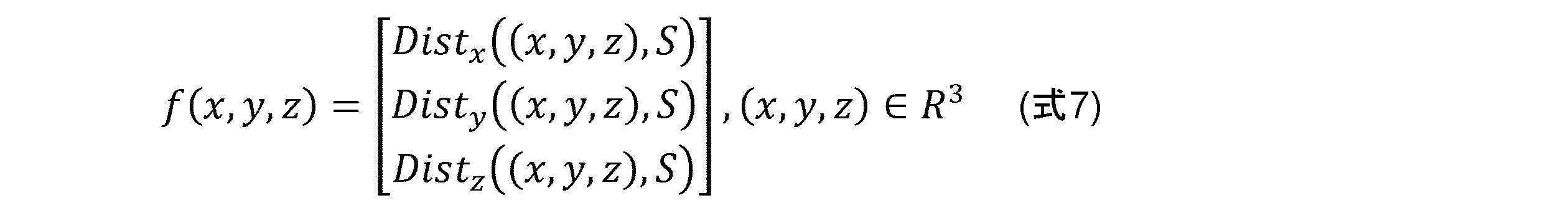
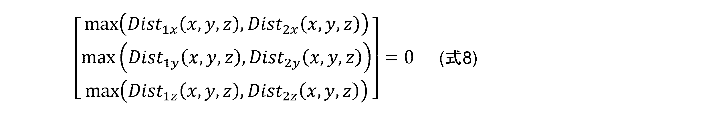
Disti((x,y,z),S)は、i軸に沿った符号付き距離関数であり、i軸は、x軸、y軸又はz軸である。ブール演算は、x軸、y軸、z軸のそれぞれにも拡張され得る。例えば、S1とS2との間の積集合は、以下の通りである。
第2の実施形態では、有向距離値は、距離方向が既知であるため、第1の実施形態のスカラー符号付き距離よりも計算が簡単である。x方向、y方向又はz方向に沿った何れの点からも、サーフェスと交差するように光線を投じることができ、次いで交点までの距離を計算することができる。 In the second embodiment, the directed distance values are easier to compute than the scalar signed distances of the first embodiment because the distance direction is known. From any point along the x, y, or z directions, a ray can be cast to intersect with the surface and the distance to the intersection point can then be calculated.
第2の実施形態の有向距離フィールド法のステップは、図7A及び7Bに示され、第1の実施形態(図4A~4B)と第2の実施形態(図7A~7B)との間の差を強調するために、図4A及び4Bを参照して、これらのステップを以下に述べる。図7Aに示される第2の実施形態の前処理では、可変ボイド距離フィールドがメッシュの代わりに生成される。同様に、図7Bでは、凍結距離フィールドがメッシュの代わりに生成される。有向距離フィールドは、可変ボイドモデル及び凍結モデルから直接生成される。ボクセルデータは、その領域から収集され、最適化ボクセルモデルを生成するためにソルバーモジュールによって最適化される。可変領域に関して、全ての選択された可変領域ジオメトリモデル710が1つの結合可変領域に統合される720。ボイド領域に関して、全ての選択されたボイドジオメトリモデル715が1つのボイド領域統合モデル725に統合される。ブロック730に示されるように、ボイド領域統合モデル725が可変領域統合モデル720から減算される。ブロック710、715、720、725及び730は、第1の実施形態のブロック410、415、420、425及び430と実質的に類似することに留意されたい。等値面メッシュがソルバー結果から取得された後、有向距離フィールド生成ブロック740は、ブロック750によって示されるように、可変ボイド等値面距離フィールドを生成する。
The steps of the directed distance field method of the second embodiment are shown in Figures 7A and 7B, and are described below with reference to Figures 4A and 4B to highlight the differences between the first embodiment (Figures 4A-4B) and the second embodiment (Figures 7A-7B). In the pre-processing of the second embodiment shown in Figure 7A, a variable void distance field is generated instead of a mesh. Similarly, in Figure 7B, a frozen distance field is generated instead of a mesh. The directed distance field is generated directly from the variable void model and the frozen model. Voxel data is collected from the region and optimized by a solver module to generate an optimized voxel model. For the variable region, all selected variable
図7Bに示されるように、第2の実施形態では、凍結領域の処理は、距離フィールドがメッシュの代わりに最終生成物として生成されることを除いて、第1の実施形態(図4B)に類似している。ユーザーは、ブロック760によって示されるように、ブロック100内の1つ又は複数の凍結領域のフェース120、130、140を選択する。ユーザーは、例えば、ブロック765によって示されるように、所望のボイド領域を取り囲むブロック材料100の部分を含む体積を定義することにより、維持する材料のエリアの厚さを割り当てる。ソリッドモデリング厚み付け法により、フェース120、130、140がソリッドモデルへと厚み付けされる。厚み付けの方向は、属するジオメトリの内側に向かい、フェース120、130、140が、属するモデルの境界を越えて厚み付けされる場合、余分な体積がカットされなければならず、これは、ブロック770によって示されるように、厚み付けされたモデル及び属するモデルの積集合(ブール演算)のみを維持しなければならないことを意味する。各フェース120、130、140の厚み付けされたモデルは、選択されたフェース120、130、140に対応する厚み付けされた部分320、330、340を含む1つの凍結モデルを形成するように統合される。最後に、凍結モデルは、距離フィールド生成モジュール780により、ブロック790によって示されるように、凍結距離フィールド300に分割される。上記の前処理は、以下に詳細に説明される後処理の実施に備えて、三角形生成のためにジオメトリモデルを結合させる。
7B, in the second embodiment, the frozen region processing is similar to the first embodiment (FIG. 4B), except that a distance field is generated as the final product instead of a mesh. The user selects one or more frozen region faces 120, 130, 140 in
第2の実施形態では、距離フィールドブール技術は、メッシュブール演算の代わりに、例えば距離フィールド関数ブールモジュール1037により、ボクセルモデル変換から生じた等値面のサーフェス材料凹凸を除去するために適用され得る。積集合、和集合及び差集合などの距離フィールドブール演算は、三角形又は四角形メッシュに適用され得る。距離フィールド関数ブールモジュール1037は、トポロジー最適化等値面距離フィールドと可変ボイド距離との間の距離フィールド積集合を行うことにより、結果として生じる距離フィールド(図示せず)を生成し、次いで結果距離フィールドと凍結距離フィールドとの間の距離フィールド和集合を行う。全ての境界形状が最終距離フィールドにおいて正確に保持される。
In a second embodiment, distance field Boolean techniques can be applied to remove surface material irregularities in the isosurface resulting from the voxel model transformation, for example by the Distance Field
第1の実施形態と同様に、ユーザーは、等値面抽出のために、より多くの材料若しくはより多くのボクセルを許容するためにボクセル密度閾値を上げることができるか、又はより少ない材料若しくはより少ないボクセルを含むようにボクセル密度を下げることができる。例えば、ボクセル密度の調節は、ユーザーにとって反復プロセスとして実施され得る。密度閾値が修正された場合、図8に示されるように、トポロジー最適化等値面メッシュ250が再生成され、且つ最終結果を生成するために、可変ボイド距離フィールド及び凍結距離フィールド300を用いて、距離フィールドブール演算が再び行われる。入力ボクセル密度データ610、荷重データ611及び境界条件612は、ブロック620によって示されるように、入力パラメーターを最適化することによってボクセルベースモデルを生成するために、ボクセルベースのソルバーモジュールに提供される。等値面モデルは、ブロック630によって示されるように、ボクセルベースモデルから生成される。ブロック835によって示されるように、等値面モデルに関する距離フィールドデータが生成される。距離フィールド積集合モデルは、ブロック840によって示されるように、生成された距離フィールド及び可変ボイド距離フィールド842の距離フィールドバイナリ積集合によって生成される。結果距離フィールドは、ブロック850によって示されるように、可変ボイド積集合モデル及び凍結距離フィールド852の距離フィールドバイナリ和集合によって生成される。結果メッシュ870は、ブロック860によって示されるように、等値面抽出により、結果距離フィールドから生成される。結果メッシュ870は、密度閾値832を調節し、且つブロック630、835、840、850及び860を繰り返すことにより、反復的に調節され得る。オリジナルのモデルにおけるシャープジオメトリフィーチャー又はクリースジオメトリフィーチャーにより良好に対応するために、拡張マーチングキューブ法又はデュアルコンタリング法が使用され得る。
As in the first embodiment, the user can increase the voxel density threshold to allow more material or more voxels for isosurface extraction, or decrease the voxel density to include less material or fewer voxels. For example, the adjustment of the voxel density can be implemented as an iterative process for the user. If the density threshold is modified, the topology optimized
上述の通り、上記に詳細に記載した機能性を実行するための本システムは、コンピューターであり得、その例を図9の概略図に示す。システム900は、プロセッサー502、ストレージデバイス504、上述の機能性を定義するソフトウェア508を内部に保存したメモリー506、入力及び出力(I/O)デバイス510(又は周辺機器)及びローカルバス又はシステム900内の通信を可能にするローカルインターフェース512を含む。ローカルインターフェース512は、例えば、当技術分野で知られているように、1つ又は複数のバス又は他の有線若しくは無線接続であり得るが、これらに限定されない。ローカルインターフェース512は、通信を可能にするために、コントローラー、バッファー(キャッシュ)、ドライバー、中継器及び受信機などの追加素子(これらは、分かりやすくするために省略されている)を有し得る。さらに、ローカルインターフェース512は、上述のコンポーネント間で適切な通信を可能にするために、アドレス、制御装置及び/又はデータ接続を含み得る。
As mentioned above, the system for performing the functionality detailed above may be a computer, an example of which is shown in the schematic diagram of FIG. 9. The
プロセッサー502は、特にメモリー506に保存されたソフトウェアを実行するためのハードウェアデバイスである。プロセッサー502は、任意の特注若しくは市販のシングルコア若しくはマルチコアプロセッサー、中央処理装置(CPU)、本システム900に関連付けられたいくつかのプロセッサー中の補助プロセッサー、半導体ベースのマイクロプロセッサー(マイクロチップ若しくはチップセットの形態)、マクロプロセッサー又は一般にソフトウェア命令を実行するための任意のデバイスであり得る。
The
メモリー506は、揮発性メモリー素子(例えば、ランダムアクセスメモリー(DRAM、SRAM、SDRAMなどのRAM))及び不揮発性メモリー素子(例えば、ROM、ハードドライブ、テープ、CDROMなど)の何れか一方又はそれらの組み合わせを含み得る。また、メモリー506は、電子、磁気、光学及び/又は他のタイプのストレージ媒体を組み込み得る。なお、メモリー506は、様々なコンポーネントが互いに遠く離れて位置するが、プロセッサー502によってアクセス可能な分散型アーキテクチャを有し得る。
Memory 506 may include volatile memory elements (e.g., random access memory (RAM, such as DRAM, SRAM, SDRAM, etc.)) and non-volatile memory elements (e.g., ROM, hard drives, tape, CD-ROM, etc.), or a combination thereof. Memory 506 may also incorporate electronic, magnetic, optical, and/or other types of storage media. Additionally, memory 506 may have a distributed architecture, with various components located remotely from one another, but accessible by
ソフトウェア508は、本発明に従って、システム900によって行われる機能性を定義する。メモリー506内のソフトウェア508は、下記のように、システム900の論理機能を実施するための実行可能命令の順序付きリストをそれぞれ含む1つ又は複数の別個のプログラムを含み得る。メモリー506は、オペレーティングシステム(O/S)520を含み得る。オペレーティングシステムは、基本的に、システム900内のプログラムの実行を制御すると共に、スケジューリング、入力-出力制御、ファイル及びデータ管理、メモリー管理並びに通信制御及び関連のサービスを提供する。
I/Oデバイス510は、例えば、キーボード、マウス、スキャナー、マイクロホンなど(ただし、これらに限定されない)の入力デバイスを含み得る。さらに、I/Oデバイス510は、例えば、プリンター、ディスプレイなど(ただし、これらに限定されない)の出力デバイスも含み得る。最後に、I/Oデバイス510は、入力及び出力の両方を用いて通信するデバイス、例えば変調器/復調器(モデム、別のデバイス、システム若しくはネットワークにアクセスするためのもの)、無線周波数(RF)若しくは他のトランシーバー、電話インターフェース、ブリッジ、ルーター又は他のデバイス(ただし、これらに限定されない)をさらに含み得る。
The I/
システム900の動作時、プロセッサー502は、上記で説明したように、メモリー506内に保存されたソフトウェア508を実行し、メモリー506とデータのやり取りを行い、且つソフトウェア508に従ってシステム900の動作を一般に制御するように構成される。
During operation of the
システム900の機能の動作時、プロセッサー502は、メモリー506内に保存されたソフトウェア508を実行し、メモリー506とデータのやり取りを行い、且つソフトウェア508に従ってシステム900の動作を一般に制御するように構成される。オペレーティングシステム520は、プロセッサー502によって読み取られ、おそらくプロセッサー502内にバッファリングされ、その後、実行される。
During operation of the functions of the
システム900がソフトウェア508に実装される場合、システム900を実装するための命令は、任意のコンピューター関連のデバイス、システム若しくは方法により又は任意のコンピューター関連のデバイス、システム若しくは方法に関連して使用される任意のコンピューター可読媒体に保存され得ることに留意されたい。このようなコンピューター可読媒体は、いくつかの実施形態では、メモリー506及びストレージデバイス504の一方又は両方に対応し得る。本明細書に関連して、コンピューター可読媒体は、コンピューター関連のデバイス、システム若しくは方法により又はコンピューター関連のデバイス、システム若しくは方法に関連して使用されるコンピュータープログラムを含むか又は保存することが可能な電子、磁気、光学又は他の物理的デバイス又は手段である。システムを実装するための命令は、プロセッサー又は他のそのような命令実行システム、装置若しくはデバイスにより或いはプロセッサー又は他のそのような命令実行システム、装置若しくはデバイスに関連して使用される任意のコンピューター可読媒体において具現化され得る。プロセッサー502を例として述べたが、このような命令実行システム、装置又はデバイスは、いくつかの実施形態では、命令実行システム、装置又はデバイスから命令をフェッチし、且つそれらの命令を実行することができる、任意のコンピューターベースのシステム、プロセッサー含有システム又は他のシステムであり得る。本明細書に関連して、「コンピューター可読媒体」は、プロセッサー又は他のそのような命令実行システム、装置若しくはデバイスにより或いはプロセッサー又は他のそのような命令実行システム、装置若しくはデバイスに関連して使用されるプログラムの保存、通信、伝搬又は輸送を行うことができる任意の手段であり得る。
It should be noted that when the
このようなコンピューター可読媒体は、例えば、電子、磁気、光学、電磁、赤外線又は半導体のシステム、装置、デバイス又は伝搬媒体であり得るが、これらに限定されない。コンピューター可読媒体のより具体的な例(非網羅的リスト)は、1つ又は複数の電線を有する電気接続(電子)、携帯フロッピーディスク(磁気)、ランダムアクセスメモリー(RAM)(電子)、リードオンリーメモリー(ROM)(電子)、消去可能プログラマブルリードオンリーメモリー(EPROM、EEPROM又はフラッシュメモリー)(電子)、光ファイバー(光学)及び携帯コンパクトディスクリードオンリーメモリー(CDROM)(光学)を含む。なお、コンピューター可読媒体は、プログラムが例えば紙又は他の媒体の光学走査によって電子的に捕捉され、その後、必要に応じてコンパイル、解釈又は適宜の方法で処理され、且つその後、コンピューターメモリーに保存され得るため、プログラムがプリントされる紙又は別の適宜の媒体であり得る。 Such computer-readable media may be, for example, but not limited to, electronic, magnetic, optical, electromagnetic, infrared or semiconductor systems, apparatus, devices or propagation media. More specific examples (non-exhaustive list) of computer-readable media include electrical connections having one or more wires (electronic), portable floppy disks (magnetic), random access memories (RAM) (electronic), read-only memories (ROM) (electronic), erasable programmable read-only memories (EPROM, EEPROM or flash memory) (electronic), optical fibers (optical) and portable compact disk read-only memories (CDROM) (optical). Note that the computer-readable medium may be paper or another suitable medium on which the program is printed, so that the program may be captured electronically, for example by optical scanning of the paper or other medium, and then compiled, interpreted or processed in any suitable manner as required, and then stored in the computer memory.
システム900がハードウェアに実装される代替実施形態では、システム900は、それぞれ当技術分野において周知の以下の技術:データ信号に対する論理関数を実装する論理ゲートを備えた1つ又は複数の別個の論理回路、適宜の組み合わせ論理ゲートを備えた特定用途向け集積回路(ASIC)、1つ又は複数のプログラマブルゲートアレイ(PGA)、フィールドプログラマブルゲートアレイ(FPGA)などの何れか又はそれらの組み合わせを用いて実装され得る。
In alternative embodiments in which
本発明の範囲又は趣旨から逸脱することなく、本発明の構造に対する様々な変更形態及び変形形態がなされ得ることが当業者に明らかであろう。上記に鑑みて、本発明の変更形態及び変形形態が以下の請求項及びそれらの均等物の範囲に入ることを条件として、本発明は、それらを包含することが意図される。 It will be apparent to those skilled in the art that various modifications and variations can be made to the structure of the present invention without departing from the scope or spirit of the invention. In view of the foregoing, it is intended that the present invention cover modifications and variations of the present invention provided they fall within the scope of the following claims and their equivalents.
100 初期ジオメトリモデル
120、130、140 フェース
150 初期ボクセル化モデル
200 トポロジー最適化ボクセルモデル
250 ボクセル抽出等値面メッシュモデル
300 凍結メッシュ
320、330、340 厚み付けされた部分
410 可変領域
415 ボイド領域
420 可変領域統合
425 ボイド領域統合
430 減算
440 メッシュ生成
450 可変ボイドメッシュ
460 凍結領域
465 厚み付け
470 属するモデルとの積集合
475 結合
480 メッシュ生成
490 凍結メッシュ
500 最終メッシュ
502 プロセッサー
504 ストレージデバイス
506 メモリー
508 ソフトウェア
510 入出力デバイス
512 ローカルバス
520 O/S
610 入力ボクセル密度データ
611 荷重
612 境界条件
620 ボクセルベースの最適化
630 等値面抽出
632 密度閾値
640 メッシュ積集合
642 可変ボイドメッシュ
650 メッシュ和集合
652 凍結メッシュ
660 結果メッシュ
710 可変領域
715 ボイド領域
720 可変領域統合
725 ボイド領域統合
730 減算
740 距離フィールドの生成
750 可変ボイド距離フィールド
760 凍結領域
765 厚み付け
770 属するモデルとの積集合
775 結合
780 距離フィールドの生成
790 凍結距離フィールド
832 密度閾値
835 距離フィールドの生成
840 距離フィールド積集合
842 可変ボイド距離フィールド
850 距離フィールド和集合
852 凍結距離フィールド
860 等値面抽出
870 結果メッシュ
900 システム
1010 XDesign設計ガイダンスモジュール
1012 入力モデル及び荷重条件
1014 トポロジー最適化
1016 結果表示
1022 前処理モジュール
1024 ボクセルベースのトポロジー最適化ソルバーモジュール
1026 結果モジュール
1032 ソリッドモデリング及びブールモジュール
1034 メッシュ生成モジュール
1035 距離フィールド関数生成モジュール
1036 等値面生成モジュール
1037 距離フィールド関数ブールモジュール
1038 メッシュブールモジュール
100
610 Input
Claims (9)
部分の3Dジオメトリモデルを受け取るステップであって、前記3Dジオメトリモデルは、境界形状を含む、ステップと、
可変ボイドメッシュを生成するために前記3Dジオメトリモデルを前処理するステップと、
前記境界形状を表す凍結メッシュを生成するために前記3Dジオメトリモデルを前処理するステップと、
前記3Dジオメトリモデルを複数のボクセルに分配するステップと、
最適化プロセスに応じて、前記複数のボクセルの各ボクセルについて密度値を調節するステップと、
ボクセルデータから抽出等値面メッシュを抽出するステップと、
前記抽出等値面メッシュと前記可変ボイドメッシュとの間のメッシュブール積集合を導出するステップと、
前記メッシュブール積集合と前記凍結メッシュとの間のメッシュブール和集合を行うステップと
を含む、コンピューターベースの方法。 1. A computer-based method comprising:
receiving a 3D geometric model of a part, said 3D geometric model including a boundary shape;
pre-processing the 3D geometric model to generate a variable void mesh;
pre-processing the 3D geometric model to generate a frozen mesh representing the boundary shape;
Distributing the 3D geometric model into a number of voxels;
adjusting a density value for each voxel of the plurality of voxels in response to an optimization process;
Extracting an extracted isosurface mesh from the voxel data;
deriving a mesh Boolean intersection between the extracted isosurface mesh and the variable void mesh;
performing a mesh Boolean union between the mesh Boolean intersection and the frozen mesh.
材料密度が可変である前記3Dジオメトリモデルの領域を含む可変モデルを定義するステップと、
材料が存在しない前記3Dジオメトリモデルの領域を含むボイドモデルを定義するステップと、
可変ボイドモデルを生成するために前記可変モデルから前記ボイドモデルを減算するステップと、
前記可変ボイドモデルから前記可変ボイドメッシュを生成するステップと
をさらに含む、請求項1に記載の方法。 Pre-processing the 3D geometric model to generate a variable void mesh includes:
defining a deformable model including regions of the 3D geometric model in which material density is variable;
defining a void model that includes areas of the 3D geometric model where no material is present;
subtracting the void model from the variable model to generate a variable void model;
and generating the variable void mesh from the variable void model.
前記複数の可変領域を前記可変モデルへと結合するステップと、
複数のボイド領域を定義するステップと、
前記複数のボイド領域を前記ボイドモデルへと結合するステップと
をさらに含む、請求項2に記載の方法。 defining a plurality of variable regions;
binding the plurality of variable regions into the variable model;
defining a plurality of void regions;
The method of claim 2 , further comprising combining the plurality of void regions into the void model.
前記境界形状の少なくとも1つのフェースをさらに含む凍結領域を定義するステップと、
前記少なくとも1つのフェースのそれぞれを厚み付けするステップと、
前記少なくとも1つの厚み付けされたフェースのそれぞれを凍結モデルへと結合するステップと、
前記凍結モデルから前記凍結メッシュを生成するステップと
をさらに含む、請求項1ないし3のいずれか一項に記載の方法。 Pre-processing the 3D geometric model to generate a frozen mesh includes:
defining a frozen region further comprising at least one face of said bounding shape;
thickening each of the at least one faces;
bonding each of the at least one thickened face to a frozen model;
The method of claim 1 , further comprising: generating the frozen mesh from the frozen model.
前記複数のボクセルの各ボクセルについて初期材料密度値を割り当てるステップと、
全体的なモデルコンプライアンスを最小限にするように前記それぞれの材料の前記密度値を調節するステップと
をさらに含む、請求項1ないし5のいずれか一項に記載の方法。 Adjusting a density value of a respective material for each voxel of the plurality of voxels in response to an optimization process includes:
assigning an initial material density value for each voxel of the plurality of voxels;
and adjusting the density values of the respective materials to minimize an overall model compliance.
Applications Claiming Priority (2)
| Application Number | Priority Date | Filing Date | Title |
|---|---|---|---|
| US15/931,779 US11217013B2 (en) | 2020-05-14 | 2020-05-14 | Method for preserving shapes in solid model when distributing material during topological optimization |
| US15/931,779 | 2020-05-14 |
Publications (2)
| Publication Number | Publication Date |
|---|---|
| JP2021185473A JP2021185473A (en) | 2021-12-09 |
| JP7692722B2 true JP7692722B2 (en) | 2025-06-16 |
Family
ID=75936774
Family Applications (1)
| Application Number | Title | Priority Date | Filing Date |
|---|---|---|---|
| JP2021069669A Active JP7692722B2 (en) | 2020-05-14 | 2021-04-16 | How to preserve shape in solid models during material allocation during topology optimization |
Country Status (3)
| Country | Link |
|---|---|
| US (1) | US11217013B2 (en) |
| EP (1) | EP3910601B1 (en) |
| JP (1) | JP7692722B2 (en) |
Families Citing this family (5)
| Publication number | Priority date | Publication date | Assignee | Title |
|---|---|---|---|---|
| EP3786899A1 (en) * | 2019-08-28 | 2021-03-03 | SO REAL Digital Twins AG | A computer-implemented method for generating a 3-dimensional wireframe model of an object comprising a plurality of parts |
| GB2607046A (en) * | 2021-05-26 | 2022-11-30 | Vitaware Ltd | Image processing method |
| CN115828585B (en) * | 2022-11-30 | 2023-07-28 | 四川大学 | Batch modification method of element material based on GiD-Code_bright software |
| CN119150606B (en) * | 2024-08-23 | 2025-07-08 | 沈阳工业大学 | A modular geometric modeling method for reciprocating compressor shafting |
| JP2025113248A (en) * | 2025-03-19 | 2025-08-01 | 任天堂株式会社 | Information processing program, information processing system, and information processing method |
Citations (7)
| Publication number | Priority date | Publication date | Assignee | Title |
|---|---|---|---|---|
| WO2010029810A1 (en) | 2008-09-11 | 2010-03-18 | 国立大学法人京都大学 | Structure optimization device, structure optimization method, and structure optimization program |
| WO2011042899A1 (en) | 2009-10-08 | 2011-04-14 | 3D M.T.P. Ltd. | Method and system enabling 3d printing of three-dimensional object models |
| US20130163836A1 (en) | 2011-12-23 | 2013-06-27 | Stmicroelectronics S.R.L. | Computing the mass of an object |
| WO2015106020A1 (en) | 2014-01-09 | 2015-07-16 | Siemens Product Lifecycle Management Software Inc. | Method for creating three dimensional lattice structures in computer-aided design models for additive manufacturing |
| WO2017147412A1 (en) | 2016-02-25 | 2017-08-31 | Stratasys Ltd. | Gpu material assignment for 3d printing using 3d distance fields |
| US20190266783A1 (en) | 2018-02-27 | 2019-08-29 | Verizon Patent And Licensing Inc. | Methods and Systems for Volumetric Reconstruction Based on a Confidence Field |
| WO2020033792A1 (en) | 2018-08-10 | 2020-02-13 | OnScale, Inc. | Hybrid meshing method for finite element analysis |
Family Cites Families (7)
| Publication number | Priority date | Publication date | Assignee | Title |
|---|---|---|---|---|
| US7369973B2 (en) * | 2000-06-29 | 2008-05-06 | Object Reservoir, Inc. | Method and system for representing reservoir systems |
| US7814441B2 (en) * | 2006-05-09 | 2010-10-12 | Inus Technology, Inc. | System and method for identifying original design intents using 3D scan data |
| US9946816B2 (en) | 2014-03-18 | 2018-04-17 | Palo Alto Research Center Incorporated | System for visualizing a three dimensional (3D) model as printed from a 3D printer |
| US10210657B2 (en) | 2015-07-24 | 2019-02-19 | The University Of British Columbia | Methods and systems for hex-mesh optimization via edge-cone rectification |
| US10395372B2 (en) | 2016-06-28 | 2019-08-27 | University Of Cincinnati | Systems, media, and methods for pre-processing and post-processing in additive manufacturing |
| WO2019062346A1 (en) | 2017-09-27 | 2019-04-04 | The Hong Kong University Of Science And Technology | Method and apparatus for modeling and designing multi-dimensional cellular structures for additive manufacturing |
| US10635088B1 (en) * | 2018-11-09 | 2020-04-28 | Autodesk, Inc. | Hollow topology generation with lattices for computer aided design and manufacturing |
-
2020
- 2020-05-14 US US15/931,779 patent/US11217013B2/en active Active
-
2021
- 2021-04-16 JP JP2021069669A patent/JP7692722B2/en active Active
- 2021-05-14 EP EP21173922.2A patent/EP3910601B1/en active Active
Patent Citations (7)
| Publication number | Priority date | Publication date | Assignee | Title |
|---|---|---|---|---|
| WO2010029810A1 (en) | 2008-09-11 | 2010-03-18 | 国立大学法人京都大学 | Structure optimization device, structure optimization method, and structure optimization program |
| WO2011042899A1 (en) | 2009-10-08 | 2011-04-14 | 3D M.T.P. Ltd. | Method and system enabling 3d printing of three-dimensional object models |
| US20130163836A1 (en) | 2011-12-23 | 2013-06-27 | Stmicroelectronics S.R.L. | Computing the mass of an object |
| WO2015106020A1 (en) | 2014-01-09 | 2015-07-16 | Siemens Product Lifecycle Management Software Inc. | Method for creating three dimensional lattice structures in computer-aided design models for additive manufacturing |
| WO2017147412A1 (en) | 2016-02-25 | 2017-08-31 | Stratasys Ltd. | Gpu material assignment for 3d printing using 3d distance fields |
| US20190266783A1 (en) | 2018-02-27 | 2019-08-29 | Verizon Patent And Licensing Inc. | Methods and Systems for Volumetric Reconstruction Based on a Confidence Field |
| WO2020033792A1 (en) | 2018-08-10 | 2020-02-13 | OnScale, Inc. | Hybrid meshing method for finite element analysis |
Also Published As
| Publication number | Publication date |
|---|---|
| CN113673005A (en) | 2021-11-19 |
| US20210358210A1 (en) | 2021-11-18 |
| EP3910601C0 (en) | 2024-04-03 |
| EP3910601A1 (en) | 2021-11-17 |
| JP2021185473A (en) | 2021-12-09 |
| US11217013B2 (en) | 2022-01-04 |
| EP3910601B1 (en) | 2024-04-03 |
Similar Documents
| Publication | Publication Date | Title |
|---|---|---|
| JP7698973B2 (en) | How to Preserve Shape in Solid Models During Material Allocation During Topology Optimization Using Distance Fields | |
| JP7692722B2 (en) | How to preserve shape in solid models during material allocation during topology optimization | |
| JP2838968B2 (en) | Mesh generation method for semiconductor device simulator | |
| JP4381743B2 (en) | Method and program for generating volume data from boundary representation data | |
| EP4022486B1 (en) | Systems and method for processing topology optimized geometries | |
| Wang et al. | Isogeometric analysis based on geometric reconstruction models | |
| JP2002024306A (en) | An analysis model data creation method and apparatus, and a recording medium recording an analysis model data creation program. | |
| CN114969860A (en) | A method for automatic generation of hexahedral unstructured mesh | |
| CN117893712B (en) | A surface structure grid generation method and device | |
| CN112823381B (en) | Techniques for generating stylized quadrilateral meshes from triangle meshes | |
| CN116702506A (en) | Method, device, equipment and medium for generating geometric model particles based on ray method | |
| Murotani et al. | Adaptive finite elements using hierarchical mesh and its application to crack propagation analysis | |
| Guo et al. | Adaptive surface mesh remeshing based on a sphere packing method and a node insertion/deletion method | |
| Phung et al. | A surface-mesh gradation tool for generating gradated tetrahedral meshes of microstructures with defects | |
| CN114170388B (en) | Octree-based dynamic modeling method for searching ellipsoid through local anisotropy | |
| CN113673005B (en) | Methods for preserving shape in a solid model when allocating materials during topology optimization | |
| CN120032065A (en) | Continuous detail layering representation and dynamic reconstruction method for large-scale triangular meshes | |
| WO2005086034A1 (en) | Numerical analysis model data generating program, numerical analysis model data generating method, and numerical analysis model data generating system | |
| CN110837707B (en) | A finite element analysis system, method, computer equipment and storage medium | |
| Hjelmervik et al. | GPU-accelerated shape simplification for mechanical-based applications | |
| WO2019103774A1 (en) | Creating and editing graded material distributions based on functional requirements | |
| Wang et al. | Fast reconstruction of water-tight surface mesh of neurons | |
| Liu et al. | High quality triangulation of implicit surfaces | |
| Vučina et al. | Exchangeable Integral and Partitioned Parameterization in 3D Shape Modeling | |
| Choe et al. | Feature sensitive out-of-core chartification of large polygonal meshes |
Legal Events
| Date | Code | Title | Description |
|---|---|---|---|
| A521 | Request for written amendment filed |
Free format text: JAPANESE INTERMEDIATE CODE: A523 Effective date: 20210908 |
|
| A621 | Written request for application examination |
Free format text: JAPANESE INTERMEDIATE CODE: A621 Effective date: 20240401 |
|
| A977 | Report on retrieval |
Free format text: JAPANESE INTERMEDIATE CODE: A971007 Effective date: 20250123 |
|
| A131 | Notification of reasons for refusal |
Free format text: JAPANESE INTERMEDIATE CODE: A131 Effective date: 20250129 |
|
| A521 | Request for written amendment filed |
Free format text: JAPANESE INTERMEDIATE CODE: A523 Effective date: 20250411 |
|
| TRDD | Decision of grant or rejection written | ||
| A01 | Written decision to grant a patent or to grant a registration (utility model) |
Free format text: JAPANESE INTERMEDIATE CODE: A01 Effective date: 20250523 |
|
| A61 | First payment of annual fees (during grant procedure) |
Free format text: JAPANESE INTERMEDIATE CODE: A61 Effective date: 20250604 |
|
| R150 | Certificate of patent or registration of utility model |
Ref document number: 7692722 Country of ref document: JP Free format text: JAPANESE INTERMEDIATE CODE: R150 |