JP7691584B1 - Ion separation device, ion separation and concentration system, and ion separation method - Google Patents
Ion separation device, ion separation and concentration system, and ion separation method Download PDFInfo
- Publication number
- JP7691584B1 JP7691584B1 JP2024562256A JP2024562256A JP7691584B1 JP 7691584 B1 JP7691584 B1 JP 7691584B1 JP 2024562256 A JP2024562256 A JP 2024562256A JP 2024562256 A JP2024562256 A JP 2024562256A JP 7691584 B1 JP7691584 B1 JP 7691584B1
- Authority
- JP
- Japan
- Prior art keywords
- electrode
- cathode
- anode
- chamber
- ion separation
- Prior art date
- Legal status (The legal status is an assumption and is not a legal conclusion. Google has not performed a legal analysis and makes no representation as to the accuracy of the status listed.)
- Active
Links
Images


Classifications
-
- B—PERFORMING OPERATIONS; TRANSPORTING
- B01—PHYSICAL OR CHEMICAL PROCESSES OR APPARATUS IN GENERAL
- B01D—SEPARATION
- B01D57/00—Separation, other than separation of solids, not fully covered by a single other group or subclass, e.g. B03C
- B01D57/02—Separation, other than separation of solids, not fully covered by a single other group or subclass, e.g. B03C by electrophoresis
-
- B—PERFORMING OPERATIONS; TRANSPORTING
- B03—SEPARATION OF SOLID MATERIALS USING LIQUIDS OR USING PNEUMATIC TABLES OR JIGS; MAGNETIC OR ELECTROSTATIC SEPARATION OF SOLID MATERIALS FROM SOLID MATERIALS OR FLUIDS; SEPARATION BY HIGH-VOLTAGE ELECTRIC FIELDS
- B03C—MAGNETIC OR ELECTROSTATIC SEPARATION OF SOLID MATERIALS FROM SOLID MATERIALS OR FLUIDS; SEPARATION BY HIGH-VOLTAGE ELECTRIC FIELDS
- B03C5/00—Separating dispersed particles from liquids by electrostatic effect
- B03C5/02—Separators
-
- C—CHEMISTRY; METALLURGY
- C02—TREATMENT OF WATER, WASTE WATER, SEWAGE, OR SLUDGE
- C02F—TREATMENT OF WATER, WASTE WATER, SEWAGE, OR SLUDGE
- C02F1/00—Treatment of water, waste water, or sewage
- C02F1/46—Treatment of water, waste water, or sewage by electrochemical methods
- C02F1/461—Treatment of water, waste water, or sewage by electrochemical methods by electrolysis
-
- C—CHEMISTRY; METALLURGY
- C02—TREATMENT OF WATER, WASTE WATER, SEWAGE, OR SLUDGE
- C02F—TREATMENT OF WATER, WASTE WATER, SEWAGE, OR SLUDGE
- C02F1/00—Treatment of water, waste water, or sewage
- C02F1/46—Treatment of water, waste water, or sewage by electrochemical methods
- C02F1/469—Treatment of water, waste water, or sewage by electrochemical methods by electrochemical separation, e.g. by electro-osmosis, electrodialysis, electrophoresis
Landscapes
- Chemical & Material Sciences (AREA)
- Chemical Kinetics & Catalysis (AREA)
- Life Sciences & Earth Sciences (AREA)
- Engineering & Computer Science (AREA)
- Electrochemistry (AREA)
- Environmental & Geological Engineering (AREA)
- General Chemical & Material Sciences (AREA)
- Hydrology & Water Resources (AREA)
- Water Supply & Treatment (AREA)
- Organic Chemistry (AREA)
- Health & Medical Sciences (AREA)
- Molecular Biology (AREA)
- Analytical Chemistry (AREA)
- Water Treatment By Electricity Or Magnetism (AREA)
- Separation Using Semi-Permeable Membranes (AREA)
Abstract
【課題】例えば、電界装置のような水を別途供給することなく、原料水からの水を透過させて、イオン分離することができるイオン分離装置及びイオン分離濃縮システムを提供する。
【解決手段】
イオン分離装置10Aは、陽イオン(Na+)及び陰イオン(Cl-)を含む電解質溶液(NaCl+H2O)である供給液11を供給する供給室12と、供給室12の両側に配置され、陽イオン(Na+)を分離する隔膜13を備えたカソードろ板電極14と、平板のアノード電極15と、分離した陽イオン(Na+)が水と共に陽イオン液(アルカリ液)16として流入する陽イオン室17と、を備えている。
【選択図】図1
An ion separation device and an ion separation and concentration system are provided that are capable of separating ions by permeating water from raw water without separately supplying water as in an electric field device.
[Solution]
The ion separation device 10A comprises a supply chamber 12 which supplies a supply liquid 11, which is an electrolyte solution (NaCl+ H2O ) containing cations (Na + ) and anions (Cl-), a cathode filter plate electrode 14 arranged on both sides of the supply chamber 12 and equipped with a diaphragm 13 which separates the cations (Na + ), a flat anode electrode 15, and a cation chamber 17 into which the separated cations (Na + ) flow together with water as cation liquid (alkaline liquid) 16.
[Selected Figure] Figure 1
Description
本発明は、イオン分離装置及びイオン分離濃縮システム及びイオン分離方法に関する。 The present invention relates to an ion separation device, an ion separation and concentration system , and an ion separation method .
従来より、溶液(電解液)中の陽イオン及び陰イオンを分離するイオン分離装置としては特許文献1に開示する技術が提案されている(特許文献1参照)。
Conventionally, the technology disclosed in
図16は、従来技術の電解水生成装置の概略図である。
特許文献1の技術においては、図16に示すような3室型の電解水生成装置を利用して、電解水を構成する酸化水、還元水が生成される。この電解水生成装置は、純水や水道水等の種々の原料水及び、この原料水に溶け込んだ塩化ナトリウム(NaCl)あるいは塩化カリウム(KCl)等の支持電解質が循環して流出入する中間室1と、この中間室1との間に陽イオン交換膜4及び陰極5が仕切りとして配設され、支持電解質のうちの陽イオン(図16において、ナトリウムイオン(Na+))が溶け込むカソード室2と、中間室1との間に陰イオン交換膜6及び陽極7が仕切りとして配設され、支持電解質のうちの陰イオン(図16において、塩化物イオン)が溶け込むアノード室3と、から構成されている。
FIG. 16 is a schematic diagram of a conventional electrolytic water generating device.
In the technology of
この電解水生成装置を用い、中間室1で支持電解質が溶け込んだ原料水を循環させ、電気分解を行うとともに、カソード室2、アノード室3に原料水をそれぞれ流し入れることにより、カソード室2から還元水8を、アノード室3から塩化物イオンを含む酸化水9を、それぞれ生成する。その際、物性を制御して還元水8及び酸化水9を生成し、これら還元水8と酸化水9を適量混合することで電解水は得られる。
Using this electrolyzed water generator, raw water with a supporting electrolyte dissolved therein is circulated in the
しかしながら、特許文献1で開示する電解水生成装置では、イオンを分離するのに、イオン交換膜を用いているが、イオン交換膜(4,6)は、陽イオン又は陰イオンをそれぞれ透過することができる専用の膜であり、水をほとんど透過させることはできない、という問題がある。
そこで、透過した各イオンを受ける流体として、カソード室2、アノード室3内に別途精製水である水(H2O)をそれぞれ供給する必要がある。この水(精製水)を供給することで、カソード室2から還元水8を、アノード室3から塩化物イオンを含む酸化水9を、排出することができる。
However, in the electrolytic water generating device disclosed in
Therefore, as a fluid to receive the permeated ions, purified water (H 2 O) must be separately supplied to the
このように、従来技術のイオン交換膜を用いる電解水生成装置では電解水を得るために、カソード室2、アノード室3内に各々キャリア水として精製水を別途供給する必要がある、という問題がある。
As such, the problem with electrolytic water generating devices using ion exchange membranes in the prior art is that in order to obtain electrolytic water, purified water must be separately supplied as carrier water to the
そこで例えば、電解水生成装置のような水を別途供給することなく、原料水からの水を透過させて、イオン分離する技術の出現が切望されている。 Therefore, there is a strong need for a technology that can separate ions by passing water through it from raw water without the need to supply water separately, as is the case with electrolytic water generators.
以上の問題に鑑み、本発明は、例えば、従来技術の電解水生成装置のような水を別途供給することなく、原料水(供給液)からの水をそのまま透過させて、イオン分離することができるイオン分離装置及びイオン分離濃縮システム及びイオン分離方法を提供する。 In view of the above problems, the present invention provides an ion separation device, an ion separation and concentration system, and an ion separation method that can separate ions by directly passing water from raw water (supply liquid) through the raw water without separately supplying water as in, for example, conventional electrolytic water generation devices.
本発明に係る第1の態様のイオン分離装置は、陽イオン及び陰イオンを含む電解質溶液である供給液を供給する供給室と、前記供給室の両側に配置され、陽イオンを分離する細孔を有する隔膜を備えたカソードろ板電極と、平板のアノード電極と、分離した陽イオンが水と共に陽イオン液として流入する陽イオン室と、を備え
前記カソードろ板電極は、
供給室側の孔を有するカソード第1電極と、
前記隔膜を挟んで陽イオン室側に設置される孔を有するカソード第2電極とからなり、
さらに、前記平板のアノード電極及びカソード第1電極に電気的に接続された第1電源と、
前記カソード第1電極と前記カソード電極第2電極とに電気的に接続される第2電源と、
を備えることを特徴とする。
The ion separation device according to a first aspect of the present invention includes a supply chamber for supplying a supply liquid, which is an electrolyte solution containing cations and anions, cathode filter plate electrodes disposed on both sides of the supply chamber and equipped with diaphragms having pores for separating cations, a flat anode electrode, and a cation chamber into which separated cations flow together with water as a cation liquid.
The cathode filter plate electrode is
a cathode first electrode having a hole on the supply chamber side;
a cathode second electrode having a hole disposed on the cation chamber side across the diaphragm;
a first power source electrically connected to the anode electrode and the cathode first electrode of the flat plate;
a second power source electrically connected to the cathode first electrode and the cathode second electrode;
The present invention is characterized by comprising :
第2の態様のイオン分離装置は、陽イオン及び陰イオンを含む電解質溶液である供給液を供給する供給室と、前記供給室の両側に配置され、陰イオンを分離する細孔を有する隔膜を備えたアノードろ板電極と、平板のカソード電極と、分離した陰イオンが水と共に陰イオン液として流入する陰イオン室と、を備え、
前記アノードろ板電極は、
供給室側の孔を有するアノード第1電極と、
前記隔膜を挟んで陰イオン室側に設置される孔を有するアノード第2電極とからなり、
さらに、前記平板のカソード電極及びアノード第1電極に電気的に接続された第3電源と、
前記アノード第1電極と前記アノード電極第2電極とに電気的に接続される第4電源と、
を備えることを特徴とする。
The ion separation device of the second aspect includes a supply chamber for supplying a supply liquid which is an electrolyte solution containing cations and anions, an anode filter plate electrode disposed on both sides of the supply chamber and equipped with a diaphragm having a pore for separating anions, a flat cathode electrode, and an anion chamber into which the separated anions flow together with water as an anion liquid ,
The anode filter plate electrode is
an anode first electrode having a hole on the supply chamber side;
an anode second electrode having a hole disposed on the anion chamber side across the diaphragm;
a third power source electrically connected to the cathode electrode and the anode first electrode of the flat plate;
a fourth power source electrically connected to the anode first electrode and the anode second electrode;
The present invention is characterized by comprising :
第3の態様のイオン分離装置は、陽イオン及び陰イオンを含む電解質溶液である供給液を供給する供給室と、前記供給室の両側に配置され、陽イオンを分離する細孔を有する隔膜を備えたカソードろ板電極と、陰イオンを分離する細孔を有する隔膜を備えたアノードろ板電極と、分離した陽イオンが水と共に陽イオン液として流入する陽イオン室と、分離した陰イオンが水と共に陰イオン液として流入する陰イオン室と、を備え、
前記カソードろ板電極は、
供給室側の孔を有するカソード第1電極と、
前記隔膜を挟んで陽イオン室側に設置される孔を有するカソード第2電極とからなると共に、
さらに、前記平板のアノード電極及びカソード第1電極に電気的に接続された第1電源と、
前記カソード第1電極と前記カソード電極第2電極とに電気的に接続される第2電源と、を備え、
前記アノードろ板電極は、
前記供給室側の孔を有するアノード第1電極と、
前記隔膜を挟んで陰イオン室側に設置される孔を有するアノード第2電極とからなると共に、
さらに、前記平板のカソード電極及びアノード第1電極に電気的に接続された第3電源と、
前記アノード第1電極と前記アノード電極第2電極とに電気的に接続される第4電源と、
を備えることを特徴とする。
The ion separation device of the third aspect includes a supply chamber for supplying a supply liquid which is an electrolyte solution containing cations and anions, a cathode filter plate electrode disposed on both sides of the supply chamber and equipped with a diaphragm having pores for separating cations, an anode filter plate electrode equipped with a diaphragm having pores for separating anions, a cation chamber into which separated cations flow together with water as a cation liquid, and an anion chamber into which separated anions flow together with water as an anion liquid ,
The cathode filter plate electrode is
a cathode first electrode having a hole on the supply chamber side;
a cathode second electrode having a hole disposed on the cation chamber side across the membrane;
a first power source electrically connected to the anode electrode and the cathode first electrode of the flat plate;
a second power source electrically connected to the cathode first electrode and the cathode second electrode;
The anode filter plate electrode is
an anode first electrode having a hole on the supply chamber side;
an anode second electrode having a hole disposed on the anion chamber side across the diaphragm;
a third power source electrically connected to the cathode electrode and the anode first electrode of the flat plate;
a fourth power source electrically connected to the anode first electrode and the anode second electrode;
The present invention is characterized by comprising :
第4の態様のイオン分離装置は、第1の態様のイオン分離装置と第2の態様のイオン分離装置とを直列につなげたものをスタックとし、このスタックを2以上直列につなげてなることを特徴とする。 The ion separation device of the fourth aspect is characterized in that the ion separation device of the first aspect and the ion separation device of the second aspect are connected in series to form a stack, and two or more of these stacks are connected in series .
第5の態様のイオン分離装置は、前記隔膜が、両側の第1カソード電極と前記第2カソード電極とに接していることを特徴とする。 In a fifth aspect of the ion separation device, the diaphragm is in contact with the first cathode electrode and the second cathode electrode on both sides .
第6の態様のイオン分離装置は、前記隔膜が、両側の第1アノード電極と前記第2アノード電極とに接していることを特徴とする。 In a sixth aspect of the ion separation device, the diaphragm is in contact with the first anode electrode and the second anode electrode on both sides .
第7の態様のイオン分離濃縮システムは、有価物と陽イオンとを含む電解質溶液中の前記有価物を濃縮する濃縮装置と、前記濃縮溶液中の陽イオンを除去する前記第1の態様のイオン分離装置と、を備えたことを特徴とする。 The seventh aspect of the ion separation and concentration system is characterized by comprising a concentrator that concentrates valuables in an electrolyte solution containing valuables and cations, and the ion separation device of the first aspect that removes cations from the concentrated solution.
第8の態様のイオン分離濃縮システムは、有価物と陰イオンとを含む電解質溶液中の前記有価物を濃縮する濃縮装置と、前記濃縮溶液中の陰イオンを除去する前記第2の態様のイオン分離装置と、を備えたことを特徴とする。 The ion separation and concentration system of the eighth aspect is characterized by comprising a concentrator that concentrates valuables in an electrolyte solution containing valuables and anions, and an ion separation device of the second aspect that removes anions from the concentrated solution.
第9の態様のイオン分離濃縮システムは、有価物と共に、陽イオン及び陰イオンの少なくとも一つを含む電解質溶液を濃縮する濃縮装置と、前記濃縮溶液の陽イオン又は陰イオンのいずれか一方又は両方を除去する第3の態様のイオン分離装置と、を備えたことを特徴とする。 The ion separation and concentration system of the ninth aspect is characterized by comprising a concentrating device that concentrates an electrolyte solution containing at least one of cations and anions together with valuables, and an ion separation device of the third aspect that removes either one or both of the cations and anions from the concentrated solution.
第10のイオン分離装置は、前記陽イオン室内で前記カソードろ板電極と対向する位置に平板のカソード電極と、を備えたことを特徴とする。 A tenth ion separation device is characterized in that it comprises a flat cathode electrode located opposite the cathode filter plate electrode in the cation chamber .
第11のイオン分離装置は、前記陰イオン室内で前記カソードろ板電極と対向する位置に平板のアノード電極と、を備えたことを特徴とする。 An eleventh ion separation device is characterized in that it comprises a flat anode electrode located opposite the cathode filter plate electrode in the anion chamber .
第12のイオン分離装置は、前記陽イオン室内で前記カソードろ板電極と対向する位置に平板のカソード電極と、
前記陰イオン室内で前記カソードろ板電極と対向する位置に平板のアノード電極と、を備えたことを特徴とする。
第13のイオン分離濃縮システムは、有価物と陽イオンとを含む電解質溶液中の前記有価物を濃縮する濃縮装置と、前記濃縮溶液中の陽イオンを除去する第10のイオン分離装置と、を備えたことを特徴とする。
第14のイオン分離濃縮システムは、有価物と陰イオンとを含む電解質溶液中の前記有価物を濃縮する濃縮装置と、
前記濃縮溶液中の陰イオンを除去する第11のイオン分離装置と、を備えたことを特徴とする。
第15のイオン分離濃縮システムは、有価物と共に、陽イオン及び陰イオンの少なくとも一つを含む電解質溶液濃縮する濃縮装置と、
前記濃縮溶液の陽イオン又は陰イオンのいずれか一方又は両方を除去する第12のイオン分離装置と、を備えたことを特徴とする。
第16の陽イオン分離方法は、
陽イオン及び陰イオンを含む電解質溶液である供給液を供給する供給室と、
前記供給室の両側に配置され、陽イオンを分離する細孔を有する隔膜を備えたカソードろ板電極と、平板のアノード電極と、
分離した陽イオンが水と共に陽イオン液として流入する陽イオン室と、を備え、
前記カソードろ板電極は、
供給室側の孔を有するカソード第1電極と、
前記隔膜を挟んで陽イオン室側に設置される孔を有するカソード第2電極とからなり、
さらに、前記平板のアノード電極及びカソード第1電極に電気的に接続された第1電源と、
前記カソード第1電極と前記カソード電極第2電極とに電気的に接続される第2電源と、を備えてなり、
前記カソード第2電極14Bを第1電位(V1)とし、
前記カソード第1電極14Aを第2電位(V2)とし、
前記平板のアノード電極15を第3電位(V3)とすると共に、
前記第1電源、前記第2電源から供給される電位はV3>V2>V1とし、前記供給室から離隔するに従ってカソード電極の電位の絶対値が大きい関係(|V1|>|V2|)として陽イオンを分離させることを特徴とする陽イオンのイオン分離方法。
第17の陰イオン分離方法は、
陽イオン及び陰イオンを含む電解質溶液である供給液を供給する供給室と、
前記供給室の両側に配置され、陰イオンを分離する細孔を有する隔膜を備えたアノードろ板電極と、平板のカソード電極と、
分離した陰イオンが水と共に陰イオン液として流入する陰イオン室と、を備え、
前記アノードろ板電極は、
前記供給室側の孔を有するアノード第1電極と、
前記隔膜を挟んで陰イオン室側に設置される孔を有するアノード第2電極とからなり、
さらに、前記平板のカソード電極及びアノード第1電極に電気的に接続された第3電源と、
前記アノード第1電極と前記アノード電極第2電極とに電気的に接続される第4電源と、を備えてなり、
前記アノード第2電極24Bをアノード第1電位(V11)とし、
前記アノード第1電極24Aをアノード第2電位(V12)とし、
前記平板のカソード電極25をカソード第4電位(V4)とすると共に、
前記第3電源43、第4電源44から供給される電位はV4<V12<V11とし、前記供給室12から離隔するに従ってアノード電極の電位の絶対値が大きい関係(|V11|>|V12|)として陰イオンを分離させることを特徴とする陰イオンのイオン分離方法。
第18の陽イオンと陰イオンとのイオン分離方法は、
陽イオン及び陰イオンを含む電解質溶液である供給液を供給する供給室と、
前記供給室の両側に配置され、陽イオンを分離する細孔を有する隔膜を備えたカソードろ板電極と、陰イオンを分離する細孔を有する隔膜を備えたアノードろ板電極と、
分離した陽イオンが水と共に陽イオン液として流入する陽イオン室と、
分離した陰イオンが水と共に陰イオン液として流入する陰イオン室と、を備え、
前記カソードろ板電極は、
前記供給室側の孔を有するカソード第1電極と、
前記隔膜を挟んで陽イオン室側に設置される孔を有するカソード第2電極とからなると共に、
さらに、前記平板のアノード電極及びカソード第1電極に電気的に接続された第1電源と、
前記カソード第1電極と前記カソード電極第2電極とに電気的に接続される第2電源と、を備え、
前記アノード電極は、
前記供給室側の孔を有するアノード第1電極と、
前記隔膜を挟んで陰イオン室側に設置される孔を有するアノード第2電極とからなると共に、
さらに、前記平板のカソード電極及びアノード第1電極に電気的に接続された第3電源と、
前記アノード第1電極と前記アノード電極第2電極とに電気的に接続される第4電源と、を備えてなり、
前記カソード第2電極を第1電位(V1)とし、
前記カソード第1電極を第2電位(V2)とし、
前記平板のアノード電極を第3電位(V3)とすると共に、前記第1電源、第2電源から供給される電位はV3>V2>V1とし、前記供給室から離隔するに従ってカソード電極の電位の絶対値が大きい関係(|V1|>|V2|)とし、
前記アノード第2電極をアノード第1電位(V11)とし、
前記アノード第1電極をアノード第2電位(V12)とし、
前記平板のカソード電極をカソード第4電位(V4)とすると共に、前記第3電源、第4電源から供給される電位はV4<V12<V11とし、
前記供給室から離隔するに従ってカアノード電極の電位の絶対値が大きい関係(|V11|>|V12|)として陽イオン及び陰イオンを分離させることを特徴とする。
The twelfth ion separation device includes a flat cathode electrode located opposite the cathode filter plate electrode in the cation chamber;
The anion chamber is characterized by comprising a flat anode electrode located opposite the cathode filter plate electrode within the anion chamber .
The thirteenth ion separation and concentration system is characterized by comprising a concentrating device that concentrates valuables in an electrolyte solution containing valuables and cations, and a tenth ion separation device that removes cations from the concentrated solution.
A fourteenth ion separation and concentration system includes a concentrator that concentrates a valuable substance in an electrolyte solution containing a valuable substance and an anion;
and an eleventh ion separation device for removing anions from the concentrated solution.
A fifteenth ion separation and concentration system includes a concentrator for concentrating an electrolyte solution containing at least one of a cation and an anion together with a valuable substance;
and a twelfth ion separation device for removing either or both of cations and anions from the concentrated solution.
A sixteenth cation separation method comprises:
a feed chamber for supplying a feed solution, the feed solution being an electrolyte solution including cations and anions;
A cathode filter plate electrode having a diaphragm having pores for separating cations, the cathode filter plate electrode being disposed on both sides of the supply chamber, and a flat anode electrode;
a cation chamber into which the separated cations flow together with water as a cation liquid;
The cathode filter plate electrode is
a cathode first electrode having a hole on the supply chamber side;
a cathode second electrode having a hole disposed on the cation chamber side across the diaphragm;
a first power source electrically connected to the anode electrode and the cathode first electrode of the flat plate;
a second power source electrically connected to the cathode first electrode and the cathode second electrode;
The cathode
The cathode
The
The potentials supplied from the first power supply and the second power supply are V3>V2>V1, and the absolute value of the potential of the cathode electrode increases as it moves away from the supply chamber (|V1|>|V2|), thereby separating cations.
A seventeenth anion separation method comprises:
a feed chamber for supplying a feed solution, the feed solution being an electrolyte solution including cations and anions;
an anode filter plate electrode having a diaphragm having pores for separating anions, the anode filter plate electrode being disposed on both sides of the supply chamber; and a flat cathode electrode.
an anion chamber into which the separated anions flow together with water as an anion liquid;
The anode filter plate electrode is
an anode first electrode having a hole on the supply chamber side;
an anode second electrode having a hole disposed on the anion chamber side across the diaphragm;
a third power source electrically connected to the cathode electrode and the anode first electrode of the flat plate;
a fourth power source electrically connected to the anode first electrode and the anode second electrode;
The anode
The anode
The
The potentials supplied from the
An eighteenth method for separating cations and anions comprises the steps of:
a feed chamber for supplying a feed solution, the feed solution being an electrolyte solution including cations and anions;
a cathode filter plate electrode provided on each side of the supply chamber and having a diaphragm having pores for separating cations; and an anode filter plate electrode provided on each side of the supply chamber and having a diaphragm having pores for separating anions;
a cation chamber into which the separated cations flow together with water as a cation liquid;
an anion chamber into which the separated anions flow together with water as an anion liquid;
The cathode filter plate electrode is
a cathode first electrode having a hole on the supply chamber side;
a cathode second electrode having a hole disposed on the cation chamber side across the membrane;
a first power source electrically connected to the anode electrode and the cathode first electrode of the flat plate;
a second power source electrically connected to the cathode first electrode and the cathode second electrode;
The anode electrode is
an anode first electrode having a hole on the supply chamber side;
an anode second electrode having a hole disposed on the anion chamber side across the diaphragm;
a third power source electrically connected to the cathode electrode and the anode first electrode of the flat plate;
a fourth power source electrically connected to the anode first electrode and the anode second electrode;
The cathode second electrode is at a first potential (V1);
The cathode first electrode is at a second potential (V2);
The flat anode electrode is set to a third potential (V3), and the potentials supplied from the first power source and the second power source are V3>V2>V1, and the absolute value of the potential of the cathode electrode increases as it is farther away from the supply chamber (|V1|>|V2|),
The anode second electrode is set to an anode first potential (V11);
The anode first electrode is at an anode second potential (V12);
The cathode electrode of the flat plate is set to a fourth cathode potential (V4), and the potentials supplied from the third power source and the fourth power source are set to V4<V12<V11.
The absolute value of the potential of the anode electrode increases with increasing distance from the supply chamber (|V11|>|V12|), thereby separating cations and anions.
本発明によれば、供給液中の陽イオン又は陰イオンのいずれか一方又は両方を効率よく分離することができる。その際、原料水(供給液)からの水をそのままろ板電極を透過させ、イオン分離することができる。 According to the present invention, it is possible to efficiently separate either or both of the cations and anions in the supply liquid. In this case, the water from the raw water (supply liquid) is directly passed through the filter plate electrode, and the ions are separated.
また、供給液中に例えば、粒子等の不純物が存在した場合でも陽イオン又は陰イオンのいずれか一方又は両方を効率よく分離することができる。 In addition, even if impurities such as particles are present in the supply liquid, either cations or anions, or both, can be separated efficiently.
供給液として塩水を用いる場合には、陽イオンと陰イオンとを分離した脱塩水を得ることができる。 When salt water is used as the supply liquid, desalted water can be obtained by separating cations and anions.
また、有価物である粒子を含む供給液中に存在する陽イオン又は陰イオンのいずれか一方又は両方を効率よく分離することができる。 In addition, it is possible to efficiently separate either or both of the cations and anions present in the supply liquid containing valuable particles.
さらに、イオン分離装置はイオン透析機能を備えることもできる。 Furthermore, the ion separation device can also be equipped with an ion dialysis function.
以下、本開示につき図面を参照しつつ詳細に説明する。なお、下記の発明を実施するための形態(以下、実施形態という)により本開示が限定されるものではない。また、下記実施形態における構成要素には、当業者が容易に想定できるもの、実質的に同一のもの、いわゆる均等の範囲のものが含まれる。さらに、下記実施形態で開示した構成要素は適宜組み合わせることが可能である。
なお、本明細書の実施形態においては、全体を通じて、同一の部材には同一の符号を付している。なお、この一実施形態は本発明の構成を具現化した例示に過ぎず、特許請求の範囲に記載した事項を逸脱することがなければ、種々の設計変更を行うことができる。
The present disclosure will be described in detail below with reference to the drawings. Note that the present disclosure is not limited to the following modes for carrying out the invention (hereinafter, referred to as embodiments). Furthermore, the components in the following embodiments include those that a person skilled in the art can easily imagine, those that are substantially the same, and those that are within the so-called equivalent range. Furthermore, the components disclosed in the following embodiments can be appropriately combined.
In the embodiments of this specification, the same components are denoted by the same reference numerals throughout. Note that this embodiment is merely an example of the configuration of the present invention, and various design changes can be made without departing from the scope of the claims.
[実施形態1]
図1は、本発明に係る実施形態1のイオン分離装置の概略図である。
実施形態1に係るイオン分離装置10Aは、電解質溶液(以下「供給液」ともいう)11である溶媒(極性溶媒;例えば、水)中に解離している陽イオンをイオン分離する装置である。ここで極性溶媒としては、例えば、水以外に、メタノール、エタノール、プロパノール等を例示することができるが本発明はこれに限定されるものではない。
ここで、供給液である電解質溶液(電解液又は電解水)とは、イオンに解離(電離)して電気伝導性を示す物質である電解質が溶け込んだ液体の総称をいう。
[Embodiment 1]
FIG. 1 is a schematic diagram of an ion separation device according to a first embodiment of the present invention.
The
Here, the electrolyte solution (electrolyte solution or electrolytic water) that is the supply liquid is a general term for a liquid that dissociates an electrolyte, which is a substance that dissociates (ionizes) into ions and exhibits electrical conductivity.
ここで、イオンの解離とは、分子(または塩や複合体等のイオン性化合物)が、通常は可逆的に、原子、イオン、ラジカル等の小さな粒子に分離または分裂する一般的なプロセスである。イオン結晶の格子は、水に溶けると壊れるものであり、この解離とは、固体イオン性化合物が溶解するときに発生するイオンの分離をいう。
一例として塩化ナトリウム(NaCl)の式単位で例示すると、塩化ナトリウム(NaCl)は、水中では1つのナトリウムイオン(Naイオン;陽(正)イオン)と1つの塩化物イオン(Clイオン:陰(負)イオン)とに解離する。
すなわち、水(H2O)に溶ける塩(塩化ナトリウム)は、それらのイオンに解離し、電解質であり、電解室溶液中には塩化ナトリウム(NaCl)が、完全に水に解離して、陽イオンのナトリウムイオン(Na+)と陰イオンの塩化物イオン(Cl-)とにイオン状態として存在する。
Here, dissociation of ions is a general process by which molecules (or ionic compounds such as salts and complexes) separate or split, usually reversibly, into smaller particles such as atoms, ions, and radicals. The lattice of an ionic crystal breaks down when it dissolves in water, and dissociation refers to the separation of ions that occurs when a solid ionic compound dissolves.
Taking the formula unit of sodium chloride (NaCl) as an example, sodium chloride (NaCl) dissociates in water into one sodium ion (Na ion; cation (positive) ion) and one chloride ion (Cl ion; anion (negative) ion).
In other words, salt (sodium chloride) that dissolves in water (H 2 O) dissociates into its ions and is an electrolyte, and in the electrolyte chamber solution, sodium chloride (NaCl) is completely dissociated into water and exists in an ionic state as cationic sodium ions (Na + ) and anionic chloride ions (Cl - ).
本実施形態では塩化ナトリウム(NaCl)を例示して説明するが、本発明はこれに限定されるものではない。
実施形態1のイオン分離装置10Aは、図1に示すように、陽イオン(Na+)及び陰イオン(Cl-)を含む電解質溶液(NaCl+H2O:以下「供給液」という)11を供給する電解質溶液供給室(以下「供給室」という)12と、供給室12の両側に配置され、陽イオン(Na+)を分離する隔膜(ろ材)13を備えたカソードろ板電極14と、平板のアノード電極15と、分離した陽イオン(Na+)が水と共に陽イオン液(以下「アルカリ液」ともいう)16として流入する陽イオン室17と、を備えている。
ここで、カソードろ板電極14は、カソード第1電極14Aとカソード第2電極14Bとから構成され、さらにカソード第1電極14Aとカソード第2電極14Bとの間に、細孔13aを有する絶縁体である隔膜(ろ板)13を挟んでいる。
ここで、隔膜13としては、例えば、セルロース等を例示することができるが、本発明はこれに限定されるものではない。
In this embodiment, sodium chloride (NaCl) is used as an example, but the present invention is not limited to this.
As shown in FIG. 1, the ion
Here, the cathode
Here, the
イオン分離装置10Aは、さらに、平板のアノード電極15及びカソード第1電極14Aに電気的に接続された第1電源41と、カソード第1電極14Aとカソード電極第2電極14Bに電気的に接続された第2電源42と、を有する。
ここで、電極構成は、カソード第2電極14Bを第1電位(V1)とし、カソード第1電極14Aを第2電位(V2)とし、平板のアノード電極15を第3電位(V3)とする。
The
Here, the electrode configuration is such that the cathode
本実施例においては、第1電源41、第2電源42により、V1=-20V、V2=-15V、V3=+15Vとなるように設定している。
なお、第1電源41,第2電源42から供給される電位はV3>V2>V1となるようにしており、供給室12から離隔するに従ってカソード電極の電位の絶対値が大きい関係(|V1|>|V2|)となるようにしている。
In this embodiment, the
The potentials supplied from the
なお、電極構成は図1の構成に限らず、カソード第1電極14Aにアースを設置して、カソード第1電極14Aを基準電極として、カソード第1電極14Aの電位(V2)を0Vとし、カソード第2電極14Bの電位(V1)を-10Vとし、平板のアノード電極15の電位(V3)を+10Vとして、電圧の絶対値を変化させて、各々の電位差は変化させない構成とすることもできる。
The electrode configuration is not limited to that shown in FIG. 1. Alternatively, the cathode
ここで、カソード第1電極14Aとカソード第2電極14Bとの間には、カソード電界Ecが発生している。カソード電界Ecは、マイナスに帯電したイオン(Cl-)が供給室12から陽イオン室17に移動することを抑制する斥力を発揮する。
Here, a cathode electric field Ec is generated between the cathode
また、カソード第1電極14Aとカソード第2電極14Bとの間に発生するカソード電界Ecは、陽イオン(Na+)とプラスに帯電した水分子とを、供給室12から陽イオン室17の方に引き込む力を発揮している。陽イオン(Na+)とプラスに帯電した水分子とは陽イオン室17の方に引き込まれる、という電気浸透流が生じる(図1の矢印F1、F2参照)。このため、供給室12の水は、単にポンプ等によるろ過圧力を受けて陽イオン室17に移動する場合の移動速度よりも加速する。よって、供給室12から陽イオン室17に移動する水の単位時間当たりの量が増加する。
In addition, the cathode electric field Ec generated between the cathode
そして、陽イオン室17に移動した陽イオン液16は、ろ過圧力により陽イオン室17の図示しない出口から外部に排出される。
なお、供給室12内で陽イオンが分離された第1供給排出液11Aは、陽イオン濃度が低下しており、ろ過圧力により供給室12の図示しない出口から外部に排出される。
Then, the cationic liquid 16 that has moved to the
The first supply/
ここで、ろ過圧力としては、図示しない供給ポンプによる圧力は、密閉空間である供給室12の圧力(ゲージ圧)が例えば0.005MPa以上0.5MPa以下、好ましくは0.02MPa以上0.1MPa以下等、大気圧よりも少し高くなるように設定するのが好ましい。
The filtration pressure applied by the supply pump (not shown) is preferably set so that the pressure (gauge pressure) of the
ここで、カソードろ板電極14(カソード第1電極14A、カソード第2電極14B)は、図中左右方向に貫通する複数の孔14aが設けられている。供給液11中の水は、電極14の孔14aを通じて、移動する。
Here, the cathode filter plate electrodes 14 (cathode
また、カソードろ板電極14(カソード第1電極14A、カソード第2電極14B)、及び平板のアノード電極15の表面には、図示しない電食防止層が設けられている。この電食防止層としては、例えば絶縁被覆層や導電性貴金属層等がある。電食防止層の材料としては、例えばチタン、アルミニウム、マグネシウム、タンタル等が挙げられるが、本発明はこれに限定されるものではない。導電性貴金属層の材料としては、例えば白金、金、パラジウム等が挙げられるが、本発明はこれに限定されるものではない。電食防止層の厚みは、絶縁被覆層の場合は、例えば5μmから30μm程度、より好ましくは5μmから10μm程度が好ましい。また、白金、金、パラジウム等の導電性貴金属層の厚みは、例えば0.5μmから10μm程度、より好ましくは1μmから5μm程度が好ましい。この電食防止層によれば、カソードろ板電極14、及び平板のアノード電極15の表面の腐食が抑制される。また、カソードろ板電極14、及び平板のアノード電極15は、絶縁被膜層を有しているため、供給液11を構成する液体と接しない。この結果、カソードろ板電極14、及び平板のアノード電極15に電位が供給されても、カソードろ板電極14、及び平板のアノード電極15の表面と液体との間で、電気分解が発生し難い。
In addition, an electrolytic corrosion prevention layer (not shown) is provided on the surface of the cathode filter plate electrode 14 (cathode
カソード第1電極14Aは、供給室12を挟んで、平板のアノード電極15と対向している。カソード第1電極14Aと平板のアノード第1電極15との間隔D1は、例えば0.1mm以上100mm以下、より好ましくは0.1mm以上40mm以下である。
The cathode
カソード第1電極14Aとカソード第2電極14Bとの間隔D2は、特に限定されないが、例えば0.1mm以上20mm以下、より好ましくは0.1mm以上2mm以下である。なお、カソード第1電極14Aとカソード第2電極14Bとの間隔D2が小さいほど、カソード第1電極14Aとカソード第2電極14Bとの間で発生するカソード電界Ecの力が強くなる。
The distance D2 between the cathode
隔膜13としては、例えばろ紙(膜)等のセルロースやナノファイバー等を例示することができるが、本発明はこれに限定されるものではない。ここでろ紙を例示すると、その細孔の大きさは、約1ミクロン(1ナノメートルの1000倍の孔径)程度である。よって、水分子はサブナノメータであるので、水は隔膜13を十分に透過する。この結果、供給室12内に、供給液11を送りこむポンプによって、隔膜13を自由に通過することとなる。
The
これに対し、陰極側のカソード第1電極14Aにマイナスイオンの塩化物イオン(Cl-)が近づいてくると、マイナスの電極とマイナスイオンとは、クーロンの斥力の関係で反発することにより、カソード第1電極14Aを透過できない。逆に、陽極の平板のアノード電極15側にプラスイオン(Na+)が近づいてくると、プラスの電極とプラスイオンとは、クーロンの斥力の関係で反発する。
In contrast, when negative chloride ions (Cl - ) approach the cathode
隔膜13としては、上述したように、ろ紙を例示できるが、誘電作用を有する隔膜を用いるのがより好ましい。誘電作用を有する隔膜は、絶縁材料から構成され、例えば、PP(ポリプロピレン)、PE(ポリエチレン)、NY(ナイロン)、セルロース等の繊維を用いた不織布を用いるようにしてもよい。
ここで、誘電作用を有する隔膜13をカソード第1電極14Aとカソード第2電極14Bとの間に設置することで、カソード第1電極14Aとカソード第2電極14Bとの間に作用するカソード電界Ecの力が大きくなる。
なお、細孔13aの孔径としては、例えば0.2mm以下とするのが好ましい。
カソード第1電極14Aとカソード第2電極14Bとの間に配置する隔膜13は接していても接していなくともよい。
ここで、この隔膜13を備えたカソードろ板電極14は、「イオンの分離膜」として機能する。
As described above, filter paper can be used as the
Here, by disposing the
The diameter of the
The
Here, the cathode
次に、図1を用いて供給液11として塩化ナトリウム溶液を供給室12内に供給して陽イオンを分離する一例を説明する。
Next, an example of separating cations by supplying a sodium chloride solution as the
上述したように供給室12内のイオン状態は、陽イオン(ナトリウムイオン:Na+)と陰イオン(塩化物イオン:Cl-)とに解離している。
供給室12内に配置されたマイナスのカソード第1電極14Aに陽イオンであるナトリウムイオン(Na+)が引き込まれる。この陽イオンであるナトリウムイオン(Na+)が引き込まれると、結果として水(H2O)も透過しながら、ナトリウムイオン(Na+)が透過する。
As described above, the ions in
Sodium ions (Na + ), which are cations, are attracted to negative cathode
これに対して、塩化物イオン(Cl-)は、陰イオンであるので、陰極側のカソード第1電極14Aに阻止されて、カソード第1電極14Aを透過することができない。図1中では、塩化物イオン(Cl-)が跳ね返る挙動を図示している。よって、供給室12内に塩化物イオン(Cl-)が濃縮される。この結果、供給室12から排出される第1供給排出液11Aは、陽イオン(Na+)が低下すると共に、塩化物イオン(Cl-)が濃縮された状態となる。
In contrast, chloride ions (Cl - ) are anions, and therefore are blocked by the cathode
本発明では陽イオン(Na+)の透過と共に、カソードろ板電極14を構成する隔膜13に対しても、水が透過することが特長である。この結果、透過した水は陽イオン(Na+)のキャリア水として作用し、精製水等の水を別途供給する必要がない。
なお、従来技術にかかる陽イオン交換膜、陰イオン交換膜は、水をほとんどもしくは僅かしか透過することができず、選択的にイオンを透過して分離する機能のみである。よって、従来技術においては、キャリア水として、別途精製水等の水を補給することを必須としている。
The present invention is characterized in that, in addition to the permeation of cations (Na + ), water also permeates through the
In addition, the cation exchange membranes and anion exchange membranes according to the conventional technology can hardly or only slightly permeate water, and only have the function of selectively permeating and separating ions, so in the conventional technology, it is essential to separately supply water such as purified water as carrier water.
この結果、イオン分離装置10Aによれば、陽イオン室17内は、陽イオンのNa+が移動された陽イオン液(アルカリ液)16を得ることができる。
As a result, according to the
なお、上述したカソードろ板電極14は、カソード第1電極14Aとカソード第2電極14Bと、さらに隔膜13を備えた一体の部材又は隔膜13を別部材として構成するようにしてもよい。
The above-mentioned cathode
[実施形態2]
図2は、実施形態2のイオン分離装置の概略図である。
なお、第1実施形態と同一の構成部材については、同一符号を付してその説明は省略する。本実施形態においても塩化ナトリウム(NaCl)を例示して説明するが、本発明はこれに限定されるものではない。
図2に示すように、本実施形態のイオン分離装置10Bは、溶媒(極性溶媒;例えば、水)中に解離している陰イオンをイオン分離する装置である。
[Embodiment 2]
FIG. 2 is a schematic diagram of an ion separation device according to the second embodiment.
In addition, the same components as those in the first embodiment are denoted by the same reference numerals and the description thereof will be omitted. In this embodiment, sodium chloride (NaCl) is also used as an example for description, but the present invention is not limited thereto.
As shown in FIG. 2, the
図2に示すように、イオン分離装置10Bは、陽イオン(Na+)及び陰イオン(Cl-)を含む供給液11を供給する供給室12と、供給室12の両側に配置され、陰イオン(Cl-)を分離する隔膜13を備えたアノードろ板電極24と、平板のカソード電極25と、分離した陰イオン(Cl-)が水と共に陰イオン液(以下「酸性液」ともいう)26として流入する陰イオン室27と、を備えている。
As shown in FIG. 2, the
ここで、アノードろ板電極24は、アノード第1電極24Aとアノード第2電極24Bとから構成され、さらにアノード第1電極24Aとアノード第2電極24Bとの間に、細孔を有する絶縁体である隔膜13を挟んでいる。この隔膜13は、絶縁材料から構成され、例えば、PP(ポリプロピレン)、PE(ポリエチレン)、NY(ナイロン)、セルロース等の繊維を用いた不織布を用いるようにしてもよい。
Here, the anode
イオン分離装置10Bは、さらに、平板のカソード電極25及びアノード第1電極24Aに電気的に接続された第3電源43と、アノード第1電極24Aとアノード電極第2電極24Bに電気的に接続された第4電源44と、を有する。
The
ここで、電極構成は、アノード第2電極24Bを第1電位(V11)とし、アノード第1電極24Aを第2電位(V12)とし、平板のカソード電極25を第4電位(V4)とする。
本実施例においては、第3電源43、第4電源44により、V11=+20V、V12=+15V、V4=-15Vとなるように設定している。
なお、第3電源43,第4電源44から供給される電位は、V4<V12<V11となるようにしており、供給室12から離隔するに従ってアノード電極の電位の絶対値が大きい関係(|V11|>|V12|)となるようにしている。
Here, the electrode configuration is such that the anode
In this embodiment, the
The potentials supplied from the
供給液11として塩化ナトリウム溶液(NaCl+H2O)を供給室12内にする一例を説明する。
上述したように供給室12内のイオン状態は、陽イオン(ナトリウムイオン:Na+)と陰イオン(塩化物イオン:Cl-)とに解離している。供給室12内に配置されたアノード第1電極24Aに陰イオンである塩化物イオン(Cl-)が引き込まれる。この陰イオンである塩化物イオン(Cl-)が引き込まれると、結果として水(H2O)も透過しながら、塩化物イオンが透過させることとなる。
An example in which a sodium chloride solution (NaCl+H 2 O) is placed in the
As described above, the ions in
これに対して、ナトリウムイオン(Na+)は、陽イオンであるので、アノード第1電極24Aに阻止されて(図2中でナトリウムイオン(Na+)が跳ね返る挙動)、アノード第1電極24Aを透過することができない。この結果、供給室12内にナトリウムイオン(Na+)が濃縮される。この結果、供給室12から排出される第2供給排出液11Bは、塩化物イオン(Cl-)が低下すると共に、陽イオン(Na+)が濃縮された状態となる。
In contrast, sodium ions (Na + ), being positive ions, are blocked by anode
アノード第1電極24Aとアノード第2電極24Bとの間隔D3は、特に限定されないが、例えば0.1mm以上20mm以下、より好ましくは0.1mm以上2mm以下である。また、アノード第1電極24Aとアノード第2電極24Bとの間隔D3が小さいほどアノード第1電極24Aとアノード第2電極24Bの間で発生するアノード電界Eaの力が強くなる。
The distance D3 between the anode
アノード第1電極24A、アノード第2電極24Bの孔24aは、供給室12と陰イオン室27を連通させている。アノード第1電極24A、アノード第2電極24Bの孔24aは、例えば0.1μm以上5000μm以下、より好ましくは100μm以上1000μm以下である。なお、アノード第1電極24A、アノード第2電極24Bの孔24aの孔径は同一でなくてもよい。
The
本発明では実施形態1で説明したように、陰イオン(Cl-)の透過と共に、水も透過することが特長である。この結果、透過した水は陰イオン(Cl-)のキャリア水として作用し、精製水等の水を別途供給することがない。この結果、透過した陰イオン(Cl-)のキャリア水として、精製水等の水を別途供給する必要がない。
従来技術にかかる陽イオン交換膜、陰イオン交換膜は、水をほとんどもしくは僅かしか透過することができず、選択的にイオンを透過して分離する機能のみである。
As described in the first embodiment, the present invention is characterized in that water also permeates along with the anion (Cl - ). As a result, the permeated water acts as carrier water for the anion (Cl - ), and purified water or other water does not need to be separately supplied. As a result, there is no need to separately supply purified water or other water as carrier water for the permeated anion (Cl - ).
The cation exchange membranes and anion exchange membranes according to the prior art are almost or only slightly permeable to water, and have only the function of selectively permeating and separating ions.
この結果、陰イオン室27内は、陰イオンのCl-が移動された陰イオン液(酸性液)26を得ることができる。
As a result, an anion liquid (acid liquid) 26 in which the anions Cl − have been transferred can be obtained in the
なお、誘電作用を有する隔膜13をアノード第1電極24Aとアノード第2電極24Bとの間に設置することで、アノード第1電極24Aとアノード第2電極24Bとの間に作用するアノード 電界Eaの力が大きくなるようにしてもよい。
In addition, a
なお、上述したアノードろ板電極24は、アノード第1電極24Aとアノード第2電極24Bと、さらに隔膜23を備えた一体の部材又は隔膜13を別部材として構成するようにしてもよい。
The above-mentioned anode
[実施形態3]
図3Aは、実施形態3のイオン分離装置の概略図である。図3Bは、実施形態3の他の形態のイオン分離装置の概略図である。なお、実施形態1、2の同一の構成部材については、同一符号を付してその説明は省略する。
図3Aに示すように、本実施形態のイオン分離装置10C-1は、実施形態1のイオン分離装置10Aと実施形態2のイオン分離装置10Bとを組み合わせたものであり、両イオン(陽イオンと陰イオン)を含む供給液から陽イオンと陰イオンとを分離し、アルカリ液16と酸性液26とを得るものである。
図3Aに示すように、実施形態3のイオン分離装置10C-1は、陽イオン及び陰イオンを含む電解質溶液(例えば、NaCl液)の供給液11を供給する電解質溶液供給室(以下「供給室」という)12と、供給室12の両側に配置され、陽イオン(Na+)を分離する隔膜(ろ紙)13を備えたカソードろ板電極14と、陰イオン(Cl-)を分離する隔膜13を備えたアノードろ板電極24と、分離した陽イオン(Na+)が水と共に陽イオン液(アルカリ液)16として流入する陽イオン室17と、分離した陰イオン(Cl-)が水と共に陰イオン液(酸性液)26として流入する陰イオン室27と、を備えてなる。
[Embodiment 3]
Fig. 3A is a schematic diagram of an ion separation device of
As shown in FIG. 3A, the
As shown in FIG. 3A, the
また、イオン分離装置10C-1は、カソード第1電極14Aとアノード第1電極24Aとに電気的に接続された第1電源41と、カソード第1電極14Aとカソード第2電極14Bとに電気的に接続された第2電源42と、アノード第1電極24Aとアノード第2電極24Bとに電気的に接続された第3電源43と、を有する。
本実施形態では、カソードろ板電極14での隔膜13としては、絶縁材料から構成され、例えば、PP(ポリプロピレン)、PE(ポリエチレン)、NY(ナイロン)、セルロース等の繊維を用いた不織布を用いるようにしてもよい。
The
In this embodiment, the
次に、図3Aを用いて供給液11として塩化ナトリウム溶液を供給室12内に供給して陽イオンと陰イオンとを分離する一例を説明する。
Next, an example of separating cations and anions by supplying sodium chloride solution as the
上述したように供給室12内のイオン状態は、陽イオン(ナトリウムイオン:Na+)と陰イオン(塩化物イオン:Cl-)とに解離している。
供給室12内に配置されたマイナスのカソード第1電極14Aに陽イオンであるナトリウムイオン(Na+)が引き込まれる。この陽イオンであるナトリウムイオン(Na+)が引き込まれると、結果として水(H2O)も透過しながら、ナトリウムイオン(Na+)が透過する。
As described above, the ions in
Sodium ions (Na + ), which are cations, are attracted to negative cathode
これに対して、塩化物イオン(Cl-)は、陰イオンであるので、マイナスのカソード第1電極14Aに阻止されて、カソード第1電極14Aを透過することができない。
In contrast, chloride ions (Cl − ) are anions and are therefore blocked by the negative cathode
本発明では陽イオン(Na+)の透過と共に、カソードろ板電極14を構成する隔膜13も水が透過することが特長である。この結果、透過して陽イオン(Na+)のキャリア水として、精製水等の水を陽イオン室17に別途供給する必要がない。
The present invention is characterized in that water permeates not only the cations (Na + ) but also the
また、供給室12内に、カソードろ板電極14と対向して配置されたアノードろ板電極(アノード第1電極24A、アノード第2電極24B)24に陰イオンである塩化物イオン(Cl-)が引き込まれる。
陰イオンである塩化物イオン(Cl-)が引き込まれると、結果として水(H2O)も透過しながら、塩化物イオンが透過することとなる。
Furthermore, chloride ions (Cl − ) , which are anions, are attracted to the anode filter plate electrodes (anode
When an anion, chloride ion (Cl - ), is attracted, the result is that the chloride ion permeates while water (H 2 O) also permeates.
これに対して、ナトリウムイオン(Na+)は、陽イオンであるので、アノード第1電極24Aに阻止されて、アノード第1電極24Aを透過することができない。
In contrast, sodium ions (Na + ) are positive ions and are therefore blocked by the anode
この結果、陽イオン室17内にナトリウムイオン(Na+)が濃縮される。また、陰イオン室27内に塩化物イオン(Cl-)が濃縮される。これにより、供給室12から排出される第3供給排出液11Cは、ナトリウムイオン(Na+)が低下すると共に、塩化物イオン(Cl-)も低下した状態となる。
As a result, sodium ions (Na + ) are concentrated in the
ここで、陽イオン室17へは、陰イオン(Cl-)の透過と共に、水も透過する。この結果、透過した水は陰イオン(Cl-)のキャリア水として作用するため、精製水等の水を別途供給する必要がない。
Here, water as well as anions (Cl − ) permeate into the
なお、従来技術にかかるイオン分離をする技術のイオン交換膜は、水をほとんど透過することができず、イオンを分離する機能のみである。これに対し、本実施形態のイオン分離装置10Cでアルカリ液16と酸性液26とを製造する場合は、キャリア水としての精製水を一切供給する必要がない。
The ion exchange membranes used in conventional ion separation technology are barely permeable to water and only function to separate ions. In contrast, when producing
以上説明したように、本実施形態のイオン分離装置10C-1によれば、供給室12内に供給した供給液11のイオン状態(ナトリウムイオン(Na+)と塩化物イオン(Cl-)との混在状態:pH=7.0)において、供給室12の左側に配置するカソードろ板電極14側ではナトリウムイオン(Na+)が透過して、陽イオン室17内にナトリウムイオン(Na+)が濃縮される。これと共に、供給室12の右側に配置するアノードろ板電極24側では塩化物イオン(Cl-)が透過して、陰イオン室27内に塩化物イオン(Cl-)が濃縮される。
As described above, according to the
このイオン分離装置10C-1での陽イオンと陰イオンとのイオン分離の確認はpHとBTB試薬で行った。ここで、供給液11として塩化ナトリウム(NaCl)の0.05%水溶液を用い、供給液量はpH7.0となるように、炭酸バッファでpHの調整をした。
同時にBTB(ブロモチモールブルー bromothymol blue;BTB)試薬を用いて、着色により各室内のpHの状態を可視化した。
The ion separation between cations and anions in this
At the same time, the pH state in each chamber was visualized by coloring using BTB (bromothymol blue; BTB) reagent.
この確認の結果、供給室12に供給する供給液11のイオン状態(ナトリウムイオン(Na+)と塩化物イオン(Cl-)との混在状態:pH=7.0)のものが、イオン分離をした結果、陽イオン室17からの排出されるアルカリ液16のpHは11.8となり、陰イオン室27からの排出される酸性液26のpHは2.4となった。
As a result of this confirmation, it was found that the ionic state of the
また、BTB試薬で検査した結果、供給室12に供給した供給液11(pH=7.0)は緑の色調であったものが、陽イオン室17の室内のアルカリ液16(pH=11.8)の色調はブルーに変色し、陰イオン室27の室内の酸性液26(pH=2.4)の色調は黄色に変色した。さらに、銅線を用いた炎色反応試験においても、アルカリ液16はNaイオンのオレンジに、酸性液26は塩化銅(CuCl2)の緑に変化していた。また、各炎色反応試験においても、イオン分離が確実になされていることを確認した。
In addition, as a result of testing with the BTB reagent, the supply liquid 11 (pH=7.0) supplied to the
この結果、供給室12から排出される第3供給排出液11Cである循環液は、ナトリウムイオン(Na+)が低下すると共に、塩化物イオン(Cl-)も低下した状態となる(pH=4.5)。
As a result, the circulating liquid that is third supply/
このBTB試薬での確認結果の概略模式図を図15に示す。
図15は、イオン分離装置でのイオン分離の状態をBTB試薬での確認した結果の概略模式図である。図15中、上段の「A」はBTB試薬の色調を示す。中段の「B」は陽イオン室17と陰イオン室27とを両サイドに備えた供給室12において、色調が変化している状態を示す。下段の「C」は供給液11の色調の状態を示す。
A schematic diagram of the results confirmed using the BTB reagent is shown in FIG.
Fig. 15 is a schematic diagram showing the results of confirming the state of ion separation in the ion separation device using the BTB reagent. In Fig. 15, "A" in the upper row shows the color tone of the BTB reagent. "B" in the middle row shows the state where the color tone changes in the
本実施形態によれば、陽イオンと陰イオンとの分離が所定の電圧を印加してカソードろ板電極14、アノードろ板電極24で各々イオン分離がなされると共に、分離した水もイオンのキャリアの水として、カソードろ板電極14、アノードろ板電極24を透過するので、従来のようにイオンキャリア水である水(精製水等)を別途添加する必要がない。
According to this embodiment, cations and anions are separated at the cathode
なお、イオン分離の際、電極(カソードろ板電極14、アノードろ板電極24)が印加されるので、電極が発熱し、供給液11が加熱される。また、水の電気分解が起こることで電極の周りにガス(陽イオン室17では水素ガス、陰イオン室27では塩素ガスと酸素ガス)が発生する。ガスは、浮力により密閉空間の供給室12の上部に移動する。よって、供給室12、陽イオン室17、陰イオン室27、又は排出ラインにはガス抜き弁等のガス抜き手段を適宜設置している。
During ion separation, a voltage is applied to the electrodes (cathode
また、図3Bに示すように、イオン分離装置10C-2は、供給室12、陽イオン室17、陰イオン室27内に、圧電部材である圧電振動子(加振部材)80を設置している。この圧電振動子(加振部材)80を設置することで、供給液11中に浮遊する微粒子が存在する場合においてもその粒子の付着を防止することができる。これにより、第1アノード電極24A、第2アノード電極24Bに印加する電圧を、圧電振動子(加振部材)80を設置しない場合よりも全体的に低くすることができる。
As shown in FIG. 3B, the
すなわち、粒子の分離を向上させるために、例えばアノード第1電極24A、アノード第2電極24Bに20Vを印加していたものを、圧電振動子(加振部材)80を設置することで、アノード第1電極24Aに5V、アノード第2電極24Bに10Vと印加電圧を半分とすることができ、全体的に印加電圧を低下させることができる。
この結果、イオン分離装置の消費電力の大幅低減を図ると共に、電気分解も抑制すること、さらには発熱も抑制することができる。
特に、熱に弱い粒子や分離対象物として、後述する生物体の分離を行う場合には、発熱低減効果は大きいものとなる。なお、圧電振動子(加振部材)80は少なくとも一か所に備えていればよい。
That is, in order to improve particle separation, for example, a voltage of 20 V applied to the anode
As a result, the power consumption of the ion separation device can be significantly reduced, and electrolysis and heat generation can also be suppressed.
In particular, when separating heat-sensitive particles or biological matter as the separation target, which will be described later, the heat reduction effect is significant. Note that it is sufficient that the piezoelectric vibrator (excitation member) 80 is provided in at least one location.
[実施形態4]
図4は、実施形態4のイオン分離装置の概略図である。
なお、第1~3の実施形態と同一の構成部材については、同一符号を付してその説明は省略する。
本実施形態4のイオン分離装置10Dは、各電極(カソードろ板電極、アノードろ板電極)を2セット(14-1,14-2、24-1,24-2)とし、陽イオン室17と陰イオン室27とを各々2セット(17-1,17-2、27-1,27-2)設けたものである。
[Embodiment 4]
FIG. 4 is a schematic diagram of an ion separation device according to the fourth embodiment.
The same components as those in the first to third embodiments are denoted by the same reference numerals and the description thereof will be omitted.
The
図示しない電源により、カソード電極14A-1、14B-1、14A-2、14B-2の電位はそれぞれ-15V、-20V、-30V、-35Vに設定されている。また、アノード電極24A-1、24B-1、24A-2、24B-2の電位はそれぞれ+15V、+20V、+30V、+35Vに設定されている。
供給室12から離隔するに従ってカソード電極(14A-1、14B-1、14A-2、14B-2)、アノード電極(24A-1、24B-1、24A-2、24B-2)のそれぞれの電位の絶対値が大きい関係となるようにしている。
The potentials of the
The absolute values of the electric potentials of the cathode electrodes (14A-1, 14B-1, 14A-2, 14B-2) and anode electrodes (24A-1, 24B-1, 24A-2, 24B-2) are set to increase with increasing distance from
図4に示すように、本実施形態4のイオン分離装置10Dは、陽イオン及び陰イオンを含む電解質溶液(例えば、NaCl液:pH7.0)供給液11を供給する供給室12と、供給室12の両側に配置され、陽イオンを分離する隔膜(ろ材)13を備えたカソードろ板電極14-1、14-2と、陰イオンを分離する隔膜(ろ材)13を備えたアノードろ板電極24-1、24-2と、分離した陽イオン(Na+)が水と共に陽イオン液(アルカリ液)16として流入する陽イオン室17(17-1、17-2)と、分離した陰イオン(Cl-))が水と共に陰イオン液(酸性液)26として流入する陰イオン室27(27-1、27-2)と、を備えてなる。
As shown in FIG. 4, the
本実施形態では、第2陽イオン室17-2と、第2陰イオン室27-2とは、各々アルカリ液16と酸性液26とを各々排出する排出室を兼ねており、各々排出孔17a、27aを備えている。なお、供給室12においても、供給孔12aと排出孔12cとを備えている。なお、排出液は循環液としている。
In this embodiment, the second cation chamber 17-2 and the second anion chamber 27-2 also serve as discharge chambers for discharging the
これにより、第2陽イオン室17―2の排出孔17aからは、陽イオン濃度が増加し、pHが上昇したアルカリ液16が排出される。
一方、第2陰イオン室27―2の排出孔27aからは、陰イオン濃度が増加し、pHが低下した酸性液26が排出される。
As a result, the
On the other hand, the
本実施形態のように、イオン分離装置10Dとして、各電極(カソードろ板電極、アノードろ板電極)を2セット(14-1,14-2、24-1,24-2)とすることで、陽イオン室17と陰イオン室27とを各々2セット(17-1,17-2、27-1,27-2)設けたることにより、イオン分離効率が増加する。
なお、本発明は各々の陽イオン室17と陰イオン室27との設置は2セットに限定されるものではなく、3セット(17-1,17-2,17-3、27-1,27-2,27-3)、4セット(17-1,17-2,17-3,17-4、27-1,27-2,27-3,27-4)と必要に応じて設置するようにしてもよい。
In this embodiment, the
In addition, in the present invention, the arrangement of each
以上説明したイオン分離装置10Aから10Dは、電解液中のイオンを分離するあらゆる技術分野に適用できる。イオンを分離する技術分野としては、イオン交換膜やイオン交換樹脂等の代替の他に例えば、海水淡水化(脱塩)装置のほか、例えば人工透析装置等にも適用できる。
The
[実施形態5]
図5は、実施形態5のイオン分離装置の概略図である。
図5に示すように、実施形態5のイオン分離装置10Eは、実施形態1のイオン分離装置10Aと、陽イオンを含む電解質溶液(供給液11)を供給する供給タンク55と、供給タンク55から供給室12に供給ポンプPを介して供給液11を供給する供給ラインL1と、供給室12からの第1供給排出液11Aを供給タンク55に循環する循環ラインL2と、陽イオン室17からのアルカリ液16をアルカリタンク56に排出するアルカリラインL3と、を備えている。
[Embodiment 5]
FIG. 5 is a schematic diagram of an ion separation device according to the fifth embodiment.
As shown in FIG. 5, the
本実施形態5のイオン分離装置10Eは、供給タンク55から供給される供給液11を供給室12内に連続して供給することで、陽イオン室17に陽イオンを分離すると共に、供給室12内を循環させることで、陽イオン液(アルカリ液)16をアルカリタンク56内に連続して得ることができる。
また、実施形態2のイオン分離装置10Bをイオン分離装置10Aの代わりに設置することで、陰イオン液(酸性液)を得ることができる。
The
Moreover, by installing the
[実施形態6]
図6は、実施形態6のイオン分離装置の概略図である。
図6に示すように、実施形態6のイオン分離装置10Fは、実施形態4のイオン分離装置10Dと、陽イオンを含む電解質溶液(供給液11)を供給する供給タンク55と、供給タンク55から供給室12に供給ポンプP-1を介して供給液11を供給する供給ラインL1と、供給室12からの第1供給排出液11Aを供給室12へ循環させるために一時的に貯留する循環タンク57と、陽イオン室17からのアルカリ液16を供給ポンプP-2によりアルカリタンク56に排出するアルカリラインL3と、供給室12からの第1供給排出液11Aを循環タンク57へ供給する供給ラインL4と、陰イオン室27から供
給ポンプP-3を介しての酸性液26を酸性液タンク58に排出する酸性ラインL5と、を備えている。
循環ラインL4には図示しない排圧弁が介装されて圧力調整(例えば、0.03MPa程度)するようにしている。
[Embodiment 6]
FIG. 6 is a schematic diagram of an ion separation device according to the sixth embodiment.
As shown in FIG. 6, the
A pressure relief valve (not shown) is provided in the circulation line L4 to adjust the pressure (for example, to about 0.03 MPa).
本実施形態6のイオン分離装置10Fとすることで、陽イオン液(アルカリ液)16をアルカリタンク56内に連続して得ることができると共に、陰イオン液(酸性液)26を酸性液タンク58内に連続して得ることができる。
By using the
ここで、図6に示すような実施形態6のイオン分離装置10Fを用い、供給液11として、硝酸ナトリウム(NaNO3)水溶液を用いて、イオン分離を行った試験結果を図7(図7A,図7B)に示す。
なお分離対象物としては、NaNO3の0.05%水溶液を用い、pH7.0に炭酸バッファでpH調整した。評価方法としては、Na+/NO3
-イオンメータにより、イオン濃度を測定した。
Here, the test results of ion separation performed using an
The separation target was a 0.05% aqueous solution of NaNO3 , whose pH was adjusted to 7.0 with a carbonate buffer. The evaluation method was to measure the ion concentration with a Na + / NO3- ion meter.
図7Aに示すように、陽イオンであるNaイオンの分離効率は95.4%(20分)、88.5%(40分)、83.1%(60分)であった。図7Bに示すように、陰イオンであるNO3イオンの分離効率は96.6%(20分)、94.9%(40分)、94.3%(60分)であった。
図7A,Bの結果より、本実施形態のイオン分離装置は陽イオンと陰イオンとを良好に分離することができることが判明した。
As shown in Figure 7A, the separation efficiency of Na ions, which are cations, was 95.4% (20 min), 88.5% (40 min), and 83.1% (60 min). As shown in Figure 7B, the separation efficiency of NO 3 ions, which are anions, was 96.6% (20 min), 94.9% (40 min), and 94.3% (60 min).
The results of FIGS. 7A and 7B show that the ion separation device of this embodiment can satisfactorily separate cations and anions.
[実施形態7]
図8は、実施形態7のイオン分離装置の概略図である。なお、上述した実施形態と同一の構成部材については、同一符号を付してその説明は省略する。
[Embodiment 7]
8 is a schematic diagram of an ion separation device according to
実施形態1~6のイオン分離装置10A~10Fは、電解液中の陽イオン又は陰イオンを分離する技術を説明したが、本発明のイオン分離装置はこれに限定されるものではない。
The
実施形態7のイオン分離装置10Gは、上述した実施形態3(図3参照)のイオン分離装置10Cと同一の構成であるが、供給室12内に供給する供給液内に粒子(図中「●」Ptcl-)50が混在した粒子混在供給液51からイオンの分離と共に、粒子50の分離を行うものである。
なお、陽イオン(例えばNaイオン)と陰イオン(例えば塩化物イオン)との分離は上述したのと同様の挙動で分離されるので、本実施形態のイオン分離装置10Eの説明においては、粒子50の分離を特に中心として説明する。
The
In addition, since cations (e.g., Na ions) and anions (e.g., chloride ions ) are separated in a manner similar to that described above, in the explanation of the
ここで、図8に示すように、イオン分離装置10Gの供給室12には粒子混在供給液51を導入する導入口12aと、導入口12aに接続される供給ポンプPを介装した供給液導入ライン12bと、粒子50,陽イオン及び陰イオンが分離された排出液51Aを排出する第3排出口12cと、第3排出口12cに接続される排出ライン12dとが設けられている。
As shown in FIG. 8, the
イオン分離装置10Gの陽イオン室17には、陽イオン液16を排出する第1排出口17aと、第1排出口17aに接続される第1排出ライン17bとが設けられている。また、イオン分離装置10Gの陰イオン室27には、陰イオン液を含む濃縮物65を排出する第2排出口27aと、第2排出口27aに接続される第2排出ライン27bとが設けられている。
The
カソード第1電極14Aは、供給室12を挟んで、アノード第1電極24Aと対向している。カソード第1電極14Aとアノード第1電極24Aとの間隔D1は、粒子混在供給液51中の粒子50をアノード第1電極24Aの方に移動させることができる間隔であり、例えば0.1mm以上100mm以下、より好ましくは0.1mm以上20mm以下である。
The cathode
なお、隔膜13の孔径13aにおいても、粒子混在供給液51中の粒子50をアノード第1電極24A、アノード第2電極24Bの方に移動させることができる間隔である。
The
イオン分離装置10Gの運転方法に関し、まず、供給ポンプPを駆動し、粒子混在供給液51を供給室12に供給する。供給ポンプPは継続して駆動させ、粒子混在供給液51の供給を連続して行う。また、供給ポンプPによる圧力は供給室12の密閉空間Sの圧力(ゲージ圧)が例えば0.005MPa以上0.5MPa以下、好ましくは0.02MPa以上0.1MPa以下等、大気圧よりも高くなるように設定する。
Regarding the method of operating the
第1排出ライン17b及び第2排出ライン27bの下流側の圧力を、図示しない圧力調整弁により、大気圧と略等しく調整する。これにより、密閉空間Sには、第1供給口12a(供給室12)から陽イオン室17及び陰イオン室27に向かう圧力(以下、ろ過圧力と称する)が作用する。
The pressure downstream of the
カソード第1電源61からカソード第1電極14Aに供給されるカソード第1電位V1を-20Vとする。カソード第2電源62からカソード第2電極14Bに供給するカソード第2電位V2を-30Vとする。つまり、カソード電源は、粒子50の極性(マイナス)と同じ極性のカソード電位(V1、V2)をカソード電極に供給する。また、供給室12から離隔するに従ってカソード電源から供給されるカソード電位の絶対値が大きい(|V2|>|V1|)。
The cathode first potential V1 supplied from the cathode
アノード第1電源63からアノード第1電極24Aに供給されるアノード第1電位V11を+20Vに設定する。アノード第2電源64からアノード第2電極24Bに供給するアノード第2電位V12を+30Vに設定する。つまり、アノード電源は、粒子50の極性(マイナス)と異なる極性のアノード電位(V11、V12)をアノード電極に供給する。また、供給室12から離隔するに従ってアノード電源から供給されるアノード電位の絶対値が大きい(|V12|>|V11|)。
The anode first potential V11 supplied from the anode
上記した運転方法によれば、供給室12に粒子混在供給液51が供給されると、粒子混在供給液51に含まれる粒子50は、同じ極性に帯電するカソード第1電極14Aから斥力を受ける(図8の矢印A1参照)。また、粒子50は、異なる極性に帯電するアノード第1電極24Aから引力を受ける(図8の矢印B1参照)。これにより、供給室12にある粒子50は、アノード第1電極24Aの方に移動する。
According to the above-mentioned operating method, when particle-
そして、アノード第1電極24Aの近傍にある粒子混在供給液51(粒子50の濃度が高い粒子混在供給液51)は、ろ過圧力によってアノード第1電極24Aの孔24aとアノード第2電極24Bとの孔24aを通過し、粒子50は陰イオン室27に移動する(図8の矢印F4参照)。また、粒子混在供給液51は、アノード第1電極24Aとアノード第2電極24Bとを通過する過程で、水の割合が減少し、かつ粒子50の割合が増加し、濃縮物65となる。以下、詳細を説明する。
The particle-mixed supply liquid 51 (particle-
以上から、プラスに帯電した水分子は、単にろ過圧力を受けて陰イオン室27に移動する場合の移動速度よりも減速する。このため、アノード第1電極24Aとアノード第2電極24Bの間を通過する単位時間当たりの水の量が減少する。この結果、陰イオン室27に移動した粒子混在供給液51に含まれる水の割合は、アノード第1電極24Aの近傍にある粒子混在供給液51と比べて小さくなる。
As a result, the positively charged water molecules move slower than they would if they were simply subjected to filtration pressure and moved to the
また、アノード第1電極24Aとアノード第2電極24Bの間のアノード電界Eaは、マイナスに帯電した粒子50を、アノード第1電極24Aからアノード第2電極24Bの方に引き込む引力を発揮する(図8の矢印F4参照)。つまり、粒子50は、アノード第1電極24Aとアノード第2電極24Bとの間を通過する際に電界から引力を受ける。これにより、粒子50は、単にろ過圧力を受けて陰イオン室27に移動する場合の移動速度よりも加速する。
以上から、アノード第1電極24Aとアノード第2電極24Bの間を通過する単位時間当たりの粒子50の量が増加する。このため、陰イオン室27に移動した粒子混在供給液51に含まれる単位容積当たりの粒子50の割合は、アノード第1電極24Aの近傍にある粒子混在供給液51と比べて高くなる。
In addition, the anode electric field Ea between the anode
As a result, the amount of
このように、粒子混在供給液51は、アノード第1電極24Aとアノード第2電極24Bの間を通過する過程で粒子50の濃度が高くなり、陰イオン液を含み粒子が濃縮された濃縮物65となる。そして、この濃縮物65は、ろ過圧力により、第2排出口27aを通過して第2排出ライン27bから排出される。
In this way, the particle-
一方で、供給室12においてカソード第1電極14Aの近傍には、粒子50の濃度が低い粒子混在供給液51が滞留する。この粒子混在供給液51は、ろ過圧力によりカソード第1電極14Aの孔14aと、カソード第2電極14Bの孔14aを通過し、陽イオン室17に移動する(図8の矢印F2参照)。
On the other hand, particle-
ここで、カソード第1電極14Aとカソード第2電極14Bの間には、カソード電界Ecが発生している。カソード電界Ecは、マイナスに帯電した粒子50が供給室12から陽イオン室17に移動することを抑制する斥力を発揮する。このため、粒子50が陽イオン室17に移動しないように抑制される。
Here, a cathode electric field Ec is generated between the cathode
また、カソード第1電極14Aとカソード第2電極14Bの間に発生するカソード電界Ecは、プラスに帯電した水分子を供給室12から陽イオン室17の方に引き込む力を発揮している。プラスに帯電した水分子は陽イオン室17の方に引き込まれる、という電気浸透流が生じる(図8の矢印F2参照)。このため、供給室12の水は、単にろ過圧力を受けて陽イオン室17に移動する場合の移動速度よりも加速する。よって、供給室12から陽イオン室17に移動する水の単位時間当たりの量が増加する。
The cathode electric field Ec generated between the cathode
そして、陽イオン室17に移動した水(粒子50が分離されたろ液)である陽イオン液16は、ろ過圧力により水が第1排出口17aから排出される。
Then, the
なお、上記したように、粒子混在供給液51に含まれる水の多くが陽イオン室17の方に移動する。つまり、単位時間当たりで供給室12から陽イオン室17又は陰イオン室27に移動する容積は、陽イオン室17の方が大きい。よって、第1バルブ17cと第2バルブ27cにより、第1排出口17aと第2排出口27aから排出する流量を例えば9:1(例えば10倍濃縮)に設定し、第1排出口17aから多くの水を排出するように調整する。これにより、第1排出口17aからは、多くの水がろ液として連続して排出される。また、第2排出口27aからは、粒子50が濃縮された濃縮物65が連続して排出される。
As described above, most of the water contained in the particle-
ここで、本実施形態では、流量を例えば9:1(例えば10倍濃縮)に設定しているが、定量ポンプの流量を調整することで、流量を例えば2:1(例えば3倍濃縮)等に適宜設定することもできる。 In this embodiment, the flow rate is set to, for example, 9:1 (e.g., 10 times concentrated), but by adjusting the flow rate of the metering pump, the flow rate can also be appropriately set to, for example, 2:1 (e.g., 3 times concentrated), etc.
ここで、粒子混在供給液51は、上述したように、陽イオン(Naイオン)と陰イオン(Clイオン)とを含んでいるので、陽イオンと陰イオンとは各々イオン分離され、アルカリ液16と酸性液26とを陽イオン室17、陰イオン室27から排出する。その際、粒子混在供給液51には粒子50が含まれているので、粒子分離も同時に行われる。
Here, as described above, the particle-
[実施形態8]
図9は、実施形態8のイオン分離装置の概略図である。
なお、第1~7の実施形態と同一の構成部材については、同一符号を付してその説明は省略する。
[Embodiment 8]
FIG. 9 is a schematic diagram of an ion separation device according to the eighth embodiment.
The same components as those in the first to seventh embodiments are given the same reference numerals and the description thereof will be omitted.
本発明のイオン分離装置は、電解液中の陽イオン又は陰イオンのイオン分離と共に、電解液中に帯電した粒子が存在した場合においても、イオン分離を行うことができる。 The ion separation device of the present invention can separate ions, either positive or negative, from an electrolyte solution, and can also separate ions when charged particles are present in the electrolyte solution.
本実施形態では供給液として水酸化ナトリウム(NaOH)水溶液用いた場合であり、この水酸化ナトリウム水溶液に粒子(図中「●」)50が混在した粒子混在供給液51を例示して説明するが、本発明はこれに限定されるものではない。
図9に示すように、実施形態8のイオン分離装置10Hは、陽イオン(Na+)及び陰イオン(OH-)、粒子50を含む粒子混在供給液51を供給する供給室12と、供給室12の両側に配置され、陽イオン(Na+)を分離する隔膜(ろ材)13を備えたカソードろ板電極14と、平板のアノード電極15と、分離した陽イオン(Na+)が水と共に陽イオン液(以下「アルカリ液」ともいう)16として流入する陽イオン室17と、を備えている。
In this embodiment, an aqueous sodium hydroxide (NaOH) solution is used as the supply liquid, and a particle-
As shown in Figure 9, the
また、実施形態8のイオン分離装置10Hには、さらに供給室12に粒子混在供給液51を供給する供給タンク55と、アルカリ液16を受けるアルカリタンク56と、粒子混在供給液51を供給タンク55から供給室12に供給ポンプPを介して供給する供給ラインL1と、供給室12からの排出液51Bを供給タンク55に循環する循環ラインL2と、陽イオン室17からのアルカリ液16をアルカリタンク56に排出するアルカリラインL3と、を備えている。
ここで、カソードろ板電極14は、各々細孔14aを有するカソード第1電極14Aとカソード第2電極14Bとから構成され、さらにカソード第1電極14Aとカソード第2電極14Bとの間に、細孔13aを有する絶縁体である隔膜13を挟んでいる。
In addition, the
Here, the cathode
次に、図9を用いて供給液として陽イオン(Na+)及び陰イオン(OH-)、マイナスに帯電した粒子(●(Ptcl-))50を含む粒子混在供給液51を供給室12内に供給して陽イオンと粒子50とを分離する一例を説明する。
Next, using Figure 9, we will explain an example of supplying a particle-
上述したように供給室12内のイオン状態は、陽イオン(ナトリウムイオン:Na+)と陰イオン(水酸イオン:OH-)とに解離している。
供給室12内に配置されたマイナスのカソード第1電極14Aに陽イオンであるナトリウムイオン(Na+)が引き込まれる。この陽イオンであるナトリウムイオン(Na+)が引き込まれると、結果として水(H2O)も透過しながら、ナトリウムイオン(Na+)が透過する。
As described above, the ions in
Sodium ions (Na + ), which are cations, are attracted to the negative cathode
これに対して、水酸化物イオン(水酸イオン:OH-)とマイナスに帯電した粒子(●(Ptcl-))50は、陰イオンであるので、マイナスのカソード第1電極14Aに阻止されて、カソード第1電極14Aを透過することができない。図9中では、供給室12内においてマイナスに帯電した粒子50が跳ね返る挙動を図示している。よって、供給室12内にマイナスに帯電した粒子50が濃縮される。この結果、供給室12から排出される排出液51Bは、陽イオン(Na+)が低下すると共に、マイナスに帯電した粒子50が濃縮された状態となる。
In contrast, hydroxide ions (hydroxide ions: OH - ) and negatively charged particles (●(Ptcl - )) 50 are anions and are therefore blocked by the negative cathode
この結果、陽イオン室17内は、陽イオンのNa+が移動された陽イオン液(ろ液であるアルカリ液)16を得ると共に、供給室12側からはマイナスに帯電した粒子50が濃縮された排出液51Bを得ることができる。
As a result, the inside of the
この結果、本実施形態によれば、粒子(●(Ptcl-))50が有価物である場合には、有価物中に含まれる不純物である陽イオン(例えば、Na+等)を容易に除去することができることとなる。 As a result, according to this embodiment, when the particle (●(Ptcl − )) 50 is a valuable resource, it becomes possible to easily remove cations (e.g., Na + , etc.) that are impurities contained in the valuable resource.
ここで、従来において、有価物が含まれる水溶液中に存在する陽イオン(例えばNaイオン)を除去するには、大量の水を用いて複数回の希釈操作と分離操作とをくり返して除去する、所謂ダイヤフィルトレーションを用いることが必要とされ、手間と労力を必要としていた。 Here, conventionally, in order to remove cations (e.g., Na ions) present in an aqueous solution containing valuable materials, it was necessary to use so-called diafiltration, in which a large amount of water was used to repeatedly perform dilution and separation operations, which required time and effort.
<試験例1>
図10Aは、実施形態8のイオン分離装置の試験例1の概略図である。
次に、図10Aを用いて供給液として陽イオン(Na+)及び陰イオン(OH-)、マイナスに帯電した粒子50を含む粒子混在供給液51を供給室12内に供給して陽イオンと陰イオンと粒子50とを分離した試験例の一例を説明する。粒子50としてはコロイダルシリカ(粒径:100nm)を用いた。
<Test Example 1>
FIG. 10A is a schematic diagram of Test Example 1 of the ion separation device of the eighth embodiment.
10A , a description will be given of an example of a test in which a particle-containing
図10Aに示すように、実施形態1のイオン分離装置10Iは、図9に示すイオン分離装置10Hにおいて、さらに供給室12からの供給排出液51Bを受ける受タンク59を設置し、この受タンク59に排出するアルカリラインL2を接続している。Na+が分離されてNa+濃度が低下した供給室12から排出される排出液(粒子(●(Ptcl-))50を含む)51Bは、受タンク59で貯留される。
10A, the ion separation device 10I of the first embodiment is further provided with a receiving
粒子混在供給液51のpHを7.0とした場合、粒子50はマイナスに帯電しているので、マイナスのカソード第1電極14Aに阻止されて、カソード第1電極14Aを透過することができない。よって、図10A中では、供給室12内に粒子50が濃縮される。この結果、供給室12から排出される排出液51Bは、陽イオン(Na+)が低下すると共に、粒子50が濃縮された状態となる。
この試験の結果を[表1]に示す。
When the pH of particle-containing
The results of this test are shown in Table 1.
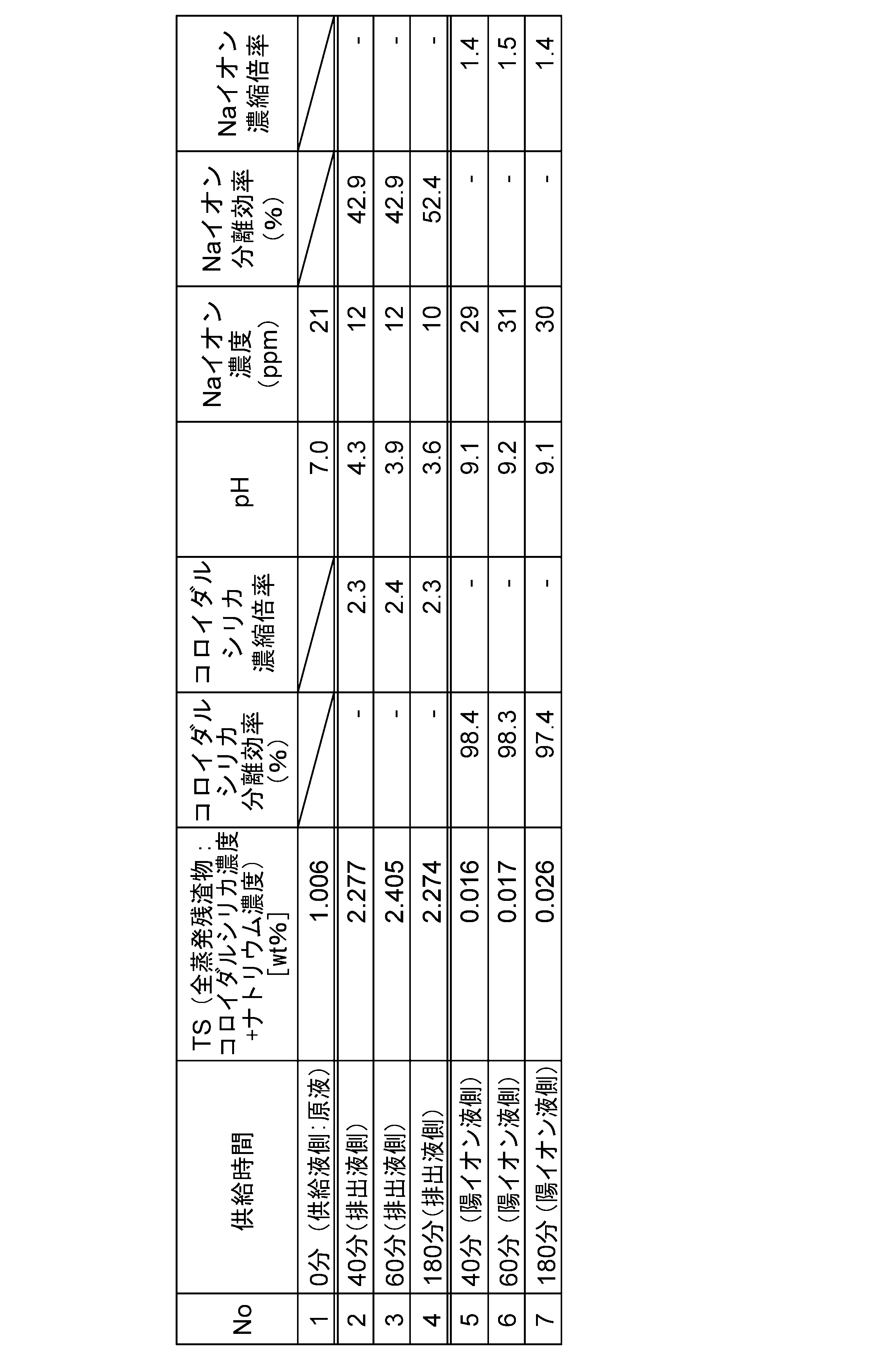
[表1]に示すように、供給液の供給時間0分の場合には、TS(全蒸発残渣物;コロイダルシリカ濃度、ナトリウム濃度)は1.006wt%、pHは7.0、Naイオン濃度は21ppmであった。
そして、排出液51B側の性状を測定すると、供給時間40分の場合には、TS(全蒸発残渣物;コロイダルシリカ濃度、ナトリウム濃度)は2.277wt%、コロイダルシリカ濃縮倍率は2.3倍、pHは4.3、Naイオン濃度は12ppm、Naイオン分離効率は42.9%であった。供給時間60分の場合には、TS(全蒸発残渣物;コロイダルシリカ濃度、ナトリウム濃度)は2.405wt%、コロイダルシリカ濃縮倍率は2.4倍、pHは3.9、Naイオン濃度は12ppm、Naイオン分離効率は42.9%であった。供給時間180分の場合には、TS(全蒸発残渣物;コロイダルシリカ濃度、ナ
トリウム濃度)は2.274wt%、コロイダルシリカ濃縮倍率は2.3倍、pHは3.6、Naイオン濃度は10ppm、Naイオン分離効率は52.4%であった。
As shown in Table 1, when the supply time of the supply liquid was 0 minutes, TS (total evaporation residue; colloidal silica concentration, sodium concentration) was 1.006 wt %, pH was 7.0, and Na ion concentration was 21 ppm.
The properties of the discharged liquid 51B were measured, and in the case of a supply time of 40 minutes, TS (total evaporation residue; colloidal silica concentration, sodium concentration) was 2.277 wt%, colloidal silica concentration ratio was 2.3 times, pH was 4.3, Na ion concentration was 12 ppm, and Na ion separation efficiency was 42.9%. In the case of a supply time of 60 minutes, TS (total evaporation residue; colloidal silica concentration, sodium concentration) was 2.405 wt%, colloidal silica concentration ratio was 2.4 times, pH was 3.9, Na ion concentration was 12 ppm, and Na ion separation efficiency was 42.9%. In the case of a supply time of 180 minutes, TS (total evaporation residue; colloidal silica concentration, sodium concentration) was 2.274 wt%, colloidal silica concentration ratio was 2.3 times, pH was 3.6, Na ion concentration was 10 ppm, and Na ion separation efficiency was 52.4%.
また、陽イオン液16側の性状を測定すると、供給時間40分の場合には、TS(全蒸発残渣物;コロイダルシリカ濃度、ナトリウム濃度)は0.016wt%、コロイダルシリカ濃縮倍率は98.4倍、pHは9.1、Naイオン濃度は29ppm、Naイオン濃縮倍率は1.4%であった。供給時間60分の場合には、TS(全蒸発残渣物;コロイダルシリカ濃度、ナトリウム濃度)は0.017wt%、コロイダルシリカ濃縮倍率は98.3倍、pHは9.2、Naイオン濃度は31ppm、Naイオン濃縮倍率は1.5%であった。供給時間180分の場合には、TS(全蒸発残渣物;コロイダルシリカ濃度、ナトリウム濃度)は0.027wt%、コロイダルシリカ濃縮倍率は97.4倍、pHは9.1、Naイオン濃度は30ppm、Naイオン濃縮倍率は1.4%であった。
In addition, when the properties of the
[表1]の結果により明らかなように、粒子混在供給液51から陽イオンであるNaイオンが分離されると共に、排出液中の粒子50であるコロイダルシリカが濃縮され、コロイダルシリカの分離効率が良好であることが判明した。
As is clear from the results in Table 1, Na ions, which are cations, were separated from the particle-containing
<試験例2>
図10Bは、実施形態8のイオン分離装置の試験例2の概略図である。
次に、図10Bに示すイオン分離装置10Jは、図9のイオン分離装置10Hにおいて、55Aに蒸留水(Distilled Water:DW)を供給する蒸留水供給タンク55Bを設置している。
試験は、試験例1と同様であり、粒子50としてはコロイダルシリカ(粒径:100nm)を用いた。
<Test Example 2>
FIG. 10B is a schematic diagram of Test Example 2 of the ion separation device of the eighth embodiment.
Next, an
The test was performed in the same manner as in Test Example 1, and colloidal silica (particle size: 100 nm) was used as the
試験例2のイオン分離装置10Jは、供給タンク55Aに蒸留水DWを供給する蒸留水供給タンク55Bを設置している。この蒸留水供給タンク55Bを設置することで、イオン分離を行う際、供給タンク55A内のスラリー(粒子+Naイオン)に対して、ろ液であるアルカリ液16の排出量と等量の蒸留水DWを供給するようにしている。
The
この蒸留水DWの供給により、供給タンク55A内のシリカの濃度と、供給タンク55Aに戻る循環液である排出液51B中のシリカ濃度とを、一定(1wt%)に保ちながら、アルカリ液16であるろ液と共に、Naイオンを排出するろ過操作方法である。
By supplying this distilled water DW, the silica concentration in the
ここで、粒子混在供給液51の供給タンク55Aからの供給室12への供給流速をF11=10ml/分、排出液51Bである循環液の戻りの流速をF12=4ml/分とした。
そして、蒸留水DWの供給流速はF14=6ml/分とし、ろ液であるアルカリ液16の排出流速を6ml/分として等量とした。
Naイオンのイオン濃度は、供給タンク55A内の初期濃度の20ppmから、循環液中のNaイオン濃度が、イオンメータによる測定では0ppmに低下していることを実証した。
Here, the supply flow rate of particle-containing
The supply flow rate of the distilled water DW was F14 = 6 ml/min, and the discharge flow rate of the
It was verified that the Na ion concentration in the circulating liquid had decreased from an initial concentration of 20 ppm in the
この試験の結果を[表2]に示す。 The results of this test are shown in Table 2.

[表2]に示すように、供給液の供給時間0分の場合には、供給液である原液中のTS(全蒸発残渣物;コロイダルシリカ濃度、ナトリウム濃度)は1.021wt%、pHは9.0、Naイオン濃度は29ppmであった。 As shown in Table 2, when the supply time of the supply liquid was 0 minutes, the TS (total evaporation residue; colloidal silica concentration, sodium concentration) in the raw liquid supply liquid was 1.021 wt%, the pH was 9.0, and the Na ion concentration was 29 ppm.
まず供給タンク55A内の原液の性状を測定すると、供給時間40分の場合には、TS(全蒸発残渣物;コロイダルシリカ濃度、ナトリウム濃度)は0.818wt%、pHは6.5、Naイオン濃度は10ppm、Naイオン分離効率は50%であった。供給時間80分の場合には、TS(全蒸発残渣物;コロイダルシリカ濃度、ナトリウム濃度)は0.802wt%、pHは4.0、Naイオン濃度は5ppm、Naイオン分離効率は75.0%であった。供給時間120分の場合には、TS(全蒸発残渣物;コロイダルシリカ濃度、ナトリウム濃度)は0.764wt%、pHは3.7、Naイオン濃度は3ppm、Naイオン分離効率は85.0%であった。供給時間150分の場合には、TS(全蒸発残渣物;コロイダルシリカ濃度、ナトリウム濃度)は0.717wt%、pHは3.7、Naイオン濃度は2ppm、Naイオン分離効率は90.0%であった。
First, the properties of the raw solution in the
次に、排出液(循環液)51B側の性状を測定すると、供給時間40分の場合には、TS(全蒸発残渣物;コロイダルシリカ濃度、ナトリウム濃度)は1.845wt%、コロイダルシリカ濃縮倍率は1.9倍、pHは3.2、Naイオン濃度は5ppm、Naイオン分離効率は75%であった。供給時間80分の場合には、TS(全蒸発残渣物;コロイダルシリカ濃度、ナトリウム濃度)は2.058wt%、コロイダルシリカ濃縮倍率は2.0倍、pHは3.2、Naイオン濃度は3ppm、Naイオン分離効率は85%であった。供給時間120分の場合には、TS(全蒸発残渣物;コロイダルシリカ濃度、ナトリウム濃度)は1.704wt%、コロイダルシリカ濃縮倍率は1.7倍、pHは3.2、Naイオン濃度は2ppm、Naイオン分離効率は90%であった。供給時間150分の場合には、TS(全蒸発残渣物;コロイダルシリカ濃度、ナトリウム濃度)は1.516wt%、コロイダルシリカ濃縮倍率は1.5倍、pHは3.2、Naイオン濃度は0ppm、Naイオン分離効率は100%であった。 Next, the properties of the discharged liquid (circulating liquid) 51B side were measured. In the case of a supply time of 40 minutes, TS (total evaporation residue; colloidal silica concentration, sodium concentration) was 1.845 wt%, colloidal silica concentration ratio was 1.9 times, pH was 3.2, Na ion concentration was 5 ppm, and Na ion separation efficiency was 75%. In the case of a supply time of 80 minutes, TS (total evaporation residue; colloidal silica concentration, sodium concentration) was 2.058 wt%, colloidal silica concentration ratio was 2.0 times, pH was 3.2, Na ion concentration was 3 ppm, and Na ion separation efficiency was 85%. In the case of a supply time of 120 minutes, TS (total evaporation residue; colloidal silica concentration, sodium concentration) was 1.704 wt%, colloidal silica concentration ratio was 1.7 times, pH was 3.2, Na ion concentration was 2 ppm, and Na ion separation efficiency was 90%. When the supply time was 150 minutes, TS (total evaporation residue; colloidal silica concentration, sodium concentration) was 1.516 wt%, the colloidal silica concentration ratio was 1.5 times, the pH was 3.2, the Na ion concentration was 0 ppm, and the Na ion separation efficiency was 100%.
また、陽イオン液16側の性状を測定すると、供給時間40分の場合には、TS(全蒸発残渣物;コロイダルシリカ濃度、ナトリウム濃度)は0.013wt%、コロイダルシリカ濃縮倍率は98.7倍、pHは10.5、Naイオン濃度は20ppm、Naイオン濃縮倍率は1.0%であった。供給時間80分の場合には、TS(全蒸発残渣物;コロイダルシリカ濃度、ナトリウム濃度)は0.009wt%、コロイダルシリカ濃縮倍率は99.1倍、pHは10.4、Naイオン濃度は11ppm、Naイオン濃縮倍率は0.6%であった。供給時間120分の場合には、TS(全蒸発残渣物;コロイダルシリカ濃度、ナトリウム濃度)は0.000wt%、コロイダルシリカ濃縮倍率は100.0倍、pHは9.9、Naイオン濃度は5ppm、Naイオン濃縮倍率は0.3%であった。
以上の結果より、循環液中のNaイオンの濃度は0ppmで分離効率100%を達成すると共に、粒子の分離効率も100%であった。この結果、粒子(●(Ptcl-))50)の100%の分離効率を達成すると共に、脱Naイオン(0ppm)を達成することができた。
In addition, when the properties of the cationic liquid 16 side were measured, in the case of a supply time of 40 minutes, TS (total evaporation residue; colloidal silica concentration, sodium concentration) was 0.013 wt%, colloidal silica concentration was 98.7 times, pH was 10.5, Na ion concentration was 20 ppm, and Na ion concentration was 1.0%. In the case of a supply time of 80 minutes, TS (total evaporation residue; colloidal silica concentration, sodium concentration) was 0.009 wt%, colloidal silica concentration was 99.1 times, pH was 10.4, Na ion concentration was 11 ppm, and Na ion concentration was 0.6%. In the case of a supply time of 120 minutes, TS (total evaporation residue; colloidal silica concentration, sodium concentration) was 0.000 wt%, colloidal silica concentration was 100.0 times, pH was 9.9, Na ion concentration was 5 ppm, and Na ion concentration was 0.3%.
From the above results, a separation efficiency of 100% was achieved when the concentration of Na ions in the circulating fluid was 0 ppm, and the particle separation efficiency was also 100%. As a result, a separation efficiency of 100% for particles (●(Ptcl - ))50) was achieved, and Na ion removal (0 ppm) was also achieved.
[実施形態9]
図11Aは、実施形態9のイオン分離装置の概略図である。なお、第1~8の実施形態と同一の構成部材については、同一符号を付してその説明は省略する。
図11Aに示すように、本実施形態9のイオン分離装置は、実施形態1のイオン分離装置10Aと実施形態2のイオン分離装置10Bとを直列につなげて、海水淡水化装置70としたものである。
[Embodiment 9]
11A is a schematic diagram of an ion separation device according to embodiment 9. Note that the same components as those in the first to eighth embodiments are given the same reference numerals and the description thereof will be omitted.
As shown in FIG. 11A, the ion separation device of the ninth embodiment is a
図11Aに示すように、実施形態9のイオン分離装置は、上述したイオン分離装置の変形例であり、図中下段側が実施形態1のイオン分離装置10Aであり、上段側が実施形態2のイオン分離装置10Bである。
As shown in FIG. 11A, the ion separation device of embodiment 9 is a modified example of the ion separation device described above, with the lower side in the figure being the
この下段側の実施形態1のイオン分離装置10Aと、上段側が実施形態2のイオン分離装置10Bとを一単位とてユニットを構成し、このユニットを複数連結することで陽イオンと陰イオンとのイオン分離効率が格段に向上する。
The
本実施形態の供給液71としては、塩水(NaCl)を用いている。図11Aに示すように、下段のイオン分離装置10Aは、陽イオンを透過して陰イオンが阻止され、上段のイオン分離装置10Bは陰イオンを透過して陽イオン阻止するものである。
すなわち、実施形態5のイオン分離装置は塩水中から陽イオンと陰イオンとを分離するので所謂海水淡水化装置として機能することができる。
In this embodiment, salt water (NaCl) is used as the
That is, the ion separation device of the fifth embodiment separates positive ions and negative ions from salt water, and therefore can function as a so-called seawater desalination device.
図11Aに示すように、実施形態9のイオン分離装置である海水淡水化装置70は、下段に第1のイオン分離装置10Aを配置し、第1のイオン分離装置10Aの供給室12内に塩化ナトリウム水溶液(塩水)71を供給する。
As shown in FIG. 11A, the
供給された塩化ナトリウム水溶液71中のナトリウムイオンは、水と共にカソードろ板電極14を透過する。この第1イオン分離装置10Aでは、Naイオンはカソードろ板電極14(14A,14B)を透過し、塩化物イオンはカソードろ板電極14に阻止され、塩化物イオンが濃縮されて供給室12から排出される。ナトリウムイオンが透過したアルカリ液16は陽イオン室17から第1陽イオン液16-1として排出される。
この第1段でのNaイオンの分離効率は95%であり、Naイオンが約95%低減する。
Sodium ions in the supplied aqueous
The separation efficiency of Na ions in this first stage is 95%, resulting in a reduction of Na ions by about 95%.
次に、第1陽イオン液16-1を上段側の第2イオン分離装置10Bの供給室22内に供給する。下段の第1イオン分離装置10Aでナトリウムイオンが濃縮された陽イオン透過液である第1陽イオン液16-1は、第2イオン分離装置10Bでは、ナトリウムイオン(Na+)がアノードろ板電極24(24A,24B)に阻止され、水だけが透過し、陰イオン室27からは脱塩水72が排出される。この第1イオン分離装置10Aと第2イオン分離装置10Bとを1セットとしてモジュールを構成し、このモジュールを複数段設置することで、Na+イオン濃度を所望濃度まで低減することができる。
Next, the first cationic liquid 16-1 is supplied into the
3.5%の海水から塩分を低減させるために、一般に0.05%塩分濃度とすると飲料として用いることができるとされている。 To reduce the salinity of seawater from 3.5%, it is generally considered necessary to reduce the salt concentration to 0.05% so that it can be used as a drink.
図11Bは、実施形態9のイオン分離装置である海水淡水化装置を複数ユニットとした海水淡水化設備の概略図である。
図11Bに示すように、海水淡水化装置70を複数のユニット構成とし、n段のモジュールとすることで塩分濃度を所望の濃度に低下させることができる。
この結果、海水淡水化装置70を複数からのユニットで構成することで、海水(塩分濃度:約3.5%)を生活水の塩分濃度まで低下することができる。
FIG. 11B is a schematic diagram of a seawater desalination facility including a plurality of units each of which is the seawater desalination apparatus, which is the ion separation apparatus of the ninth embodiment.
As shown in FIG. 11B, the
As a result, by configuring the
このように、一般に海水淡水化装置として用いている逆浸透膜を用いた逆浸透膜法では、塩分濃度が3.5%の海水を0.05%塩分濃度とすることで飲料水として用いているが、これと同程度、あるいは同程度以上のナトリウムイオン濃度に脱塩することができる。 In this way, the reverse osmosis membrane method, which uses reverse osmosis membranes that are generally used in seawater desalination equipment, can desalinate seawater with a salt concentration of 3.5% to a salt concentration of 0.05% so that it can be used as drinking water, but it can also desalinate seawater to a sodium ion concentration of the same or higher.
また、海水中に粒子(例えばプランクトン等の生物体、有機質、無機質等:(●(Ptcl-))50がある場合においても、上述したように、帯電した粒子50も分離できるので、海水淡水化を行うことができる。
粒子はいずれかに帯電していると分離できる。
Furthermore, even if there are particles (e.g., living organisms such as plankton, organic matter, inorganic matter, etc.: (●( Ptcl- )) 50 in the seawater, as described above, the charged
Particles can be separated if they are charged to one side or the other.
なお、従来の逆浸透膜装置による海水淡水化は粒子(例えばプランクトン等の生物体、有機質、無機質等:(●(Ptcl-))50があると逆浸透膜の目詰まりとなるので、逆浸透膜装置の前段で処理していた。 In addition, in conventional seawater desalination using reverse osmosis membrane equipment, the presence of particles (e.g., living organisms such as plankton, organic matter, inorganic matter, etc.: (●(Ptcl − )) 50 would clog the reverse osmosis membrane, so the particles were treated at a stage upstream of the reverse osmosis membrane equipment.
すなわち、従来技術における逆浸透膜法の海水淡水化は、海水を前処理において、極限まで磨きた綺麗な水とし、サブナノメータの逆浸透膜の細孔の目詰まりを防止していた。 In other words, in conventional seawater desalinization using the reverse osmosis membrane method, seawater is pretreated to be purified to the utmost extent possible, preventing clogging of the sub-nanometer pores in the reverse osmosis membrane.
これに対し、本発明のイオン分離装置を用いた海水淡水化装置70では、帯電している粒子(●(Ptcl-))50も分離できるので、多少プランクトン等があっても帯電したものあれば分離処理が可能となる。
In contrast, in a
すなわち、マイナスに帯電した粒子は下段の第1処理のイオン分離装置10Aで阻止できるし、プラスに帯電した粒子は上段の第2処理のイオン分離装置10Bで阻止できる。
That is, negatively charged particles can be blocked by the first-stage
一般に海水を淡水化する技術としては、「逆浸透膜法」がある。この逆浸透膜法は、人工的に浸透圧以上の高圧力を塩水側にかけ、塩水にある水の分子だけを半透膜を超えて、淡水側に押し出すという「逆浸透現象」を利用する技術である。 A common technique for desalinating seawater is the "reverse osmosis membrane method." This method uses the "reverse osmosis phenomenon," in which an artificial high pressure greater than the osmotic pressure is applied to the saltwater, forcing only the water molecules in the saltwater through a semipermeable membrane into the freshwater.
この従来技術の逆浸透膜法による海水淡水化方法では、例えば、海水淡水化プラントからは塩分を濃縮したブライン水の発生が問題となる。ほとんどの場合、未処理のブラインをそのまま海へ廃棄しているので、廃棄物の中に含まれるスケール防止剤や防汚剤等の有害な化学物質が海を汚染し、海洋生物や海の生態系に悪影響を与える重大なリスクがある、という問題がある。さらにブラインは、塩分を多く含むため受水域の塩分に比べて、塩分濃度が高くなり、その結果、受水域の溶存酸素(Dissolved Oxygen:DO)を消費するという問題もある。 In the conventional seawater desalination method using reverse osmosis membranes, for example, a problem arises in that salt-concentrated brine water is generated from the seawater desalination plant. In most cases, untreated brine is simply dumped into the sea, which poses a serious risk that harmful chemicals such as anti-scalant agents and antifouling agents contained in the waste will pollute the sea and have a negative impact on marine life and the marine ecosystem. In addition, because brine contains a lot of salt, its salinity is higher than that of the receiving water, which results in the problem of consuming dissolved oxygen (DO) in the receiving water.
本発明のイオン分離装置を応用した海水淡水化装置70は、このようなブライン水の問題もない。そもそも、逆浸透膜法では逆浸透膜に供給する海水は、前処理工程が必要となるが、本発明の海水淡水化装置では、前処理装置としては、海水中の不純物を除去するための「砂ろ過装置」のみの簡易な前処理設備を設置することで済むので、効率的である。
The
[実施形態10]
図12,図13は、実施形態10のイオン分離装置の概略図である。
なお、上述した実施形態の同一の構成部材については、同一符号を付してその説明は省略する。
図12のイオン分離装置は電極配置をアクティブ電極配置であり、図13のイオン分離装置は電極配置をパッシブ電極配置としている。
[Embodiment 10]
12 and 13 are schematic diagrams of an ion separation device according to a tenth embodiment.
In addition, the same components as those in the above-mentioned embodiment are denoted by the same reference numerals and the description thereof will be omitted.
The ion separation device in FIG. 12 has an active electrode arrangement, while the ion separation device in FIG. 13 has a passive electrode arrangement.
図12のイオン分離装置10Kは、8極の電極全てに電源を接続して供給するものである。
本実施形態4のイオン分離装置10Dは、各電極(カソードろ板電極、アノードろ板電極)を2セット(14-1,14-2、24-1,24-2)とし、陽イオン室17と陰イオン室27とを各々2セット(17-1,17-2、27-1,27-2)設けたものである。
The
The
電源(ES1,ES2,IS1,IS2,IS3,IS4,IS5,IS6)により、カソード電極14A-1、14B-1、14A-2、14B-2の電位はそれぞれ-15V、-20V、-30V、-35Vに設定されている。また、アノード電極24A-1、24B-1、24A-2、24B-2の電位はそれぞれ+15V、+20V、+30V、+35Vに設定されている。
供給室12から離隔するに従ってカソード電極(14A-1、14B-1、14A-2、14B-2)、アノード電極(24A-1、24B-1、24A-2、24B-2)のそれぞれの電位の絶対値が大きい関係となるように設定している。
これに対して、図13のイオン分離装置10Lは、両端の2極の電極にのみ電源を接続して、-35V及び+35Vの電位を供給するものである。
図12、13中、一点鎖線の枠線でイオン分離室を示している。なお、本実施形態のイオン分離装置10K,10Lには圧電振動子80が配置されている。
The power supplies (ES1, ES2, IS1, IS2, IS3, IS4, IS5, IS6) set the potentials of the
The absolute values of the electric potentials of the cathode electrodes (14A-1, 14B-1, 14A-2, 14B-2) and anode electrodes (24A-1, 24B-1, 24A-2, 24B-2) are set to increase with increasing distance from
In contrast, the
12 and 13, the ion separation chamber is indicated by a dashed line frame. In addition, a
[実施形態11]
図14は、実施形態11のイオン分離装置を備えたイオン分離濃縮システムの概略図である。
[Embodiment 11]
FIG. 14 is a schematic diagram of an ion separation and concentration system including the ion separation device of the eleventh embodiment.
図14に示すように、実施形態11のイオン分離濃縮システム100は、有価物である粒子50を含む希釈溶液101を粒子50と共に、陽イオン及び陰イオンの少なくとも一つを含む希薄溶液(陽イオン、有価物)を濃縮して濃縮有価物103とする有価物濃縮装置102と、濃縮有価物103中の陽イオン又は陰イオンのいずれか一方又は両方を除去するイオン分離装置104(例えば、前述した実施形態のイオン分離装置10A、イオン分離装置10B、イオン分離装置10C、イオン分離装置10Hのいずれか)と、を備えている。なお、図14ではイオンとして陽イオンを図示している。
As shown in FIG. 14, the ion separation and
有価物濃縮装置としては、例えば、回転式セラミック膜ろ過機(「ダイナフィルター;登録商標」)等のろ過装置を例示することができるが、本発明はこれに限定されるもので
はない。
An example of the valuables concentrator is a filtration device such as a rotary ceramic membrane filter (Dynafilter; registered trademark), but the present invention is not limited to this.
本実施形態のイオン分離濃縮システム100によれば、有価物の濃度が低い希釈溶液を濃縮装置102で一度濃縮し、その後の濃縮有価物103から不純物である陽イオン(Naイオン)を分離することができる。
According to the ion separation and
この結果、有価物の濃縮を行うと共に、有価物中のイオン濃度が低下し、有価物純度が向上する。 As a result, the valuables are concentrated, the ion concentration in the valuables decreases, and the purity of the valuables improves.
すなわち、図9を用いて実施形態8のイオン分離装置10Hで説明したように、粒子(●(Ptcl-))50をそのまま循環しつつ、陽イオン(Naイオン)を分離することで、粒子(●(Ptcl-))50が有価物である場合には、有価物中に含まれる不純物である陽イオン(例えば、Na+等)を容易に除去することができることとなり、製品純度の向上を図ることができる。
That is, as explained in the
[実施形態11]
図17は、実施形態11の他のイオン分離装置の概略図である。
なお、上述した実施形態と同一の構成部材については、同一符号を付してその説明は省略する。
[Embodiment 11]
FIG. 17 is a schematic diagram of another ion separation device according to the eleventh embodiment.
In addition, the same components as those in the above-mentioned embodiment are given the same reference numerals and the description thereof will be omitted.
図17のイオン分離装置10Mは、従来技術のいわゆるイオン交換膜機能を備えたイオン分離装置である。
The
本実施形態では塩化ナトリウム(NaCl)を例示して説明する。
実施形態11のイオン分離装置10Mは、図17に示すように、陽イオン(Na+)及び陰イオン(Cl-)を含む電解質溶液(NaCl+H2O:以下「供給液」という)11を供給する電解質溶液供給室(以下「供給室」という)12と、供給室12の両側に配置され、陽イオン(Na+)を分離する隔膜(ろ材)13を備えたカソードろ板電極14と、平板のアノード電極(陽極)15と、分離した陽イオン(Na+)が水と共に陽イオン液(以下「アルカリ液」ともいう)110として流入する陽イオン室17と、さらに、陽イオン室17内でカソードろ板電極14と対向する位置に設けた平板のカソード電極(陰極)25と、を備えている。
そして供給室12には、図示しない供給口と排出口とが設けられ、供給室12内に電解液である供給液11を供給している。
In this embodiment, sodium chloride (NaCl) will be used as an example.
As shown in FIG. 17, the ion
陽イオン室17には、移動した陽イオンを置換する置換液を供給する、図示しない置換液供給口と置換液排出口とが設けられており、陽イオン室17内に置換液110を供給している。この置換液110は、カソードろ板電極14によるイオン交換によって、陽イオン室17内に移動された陽イオン(Na+)を置換し、アルカリ液110Aとしている。
The
ここで、カソードろ板電極14は、カソード第1電極14Aとカソード第2電極14Bとから構成され、さらにカソード第1電極14Aとカソード第2電極14Bとの間に、細孔13aを有する絶縁体である隔膜(ろ板)13を挟んでいる。
ここで、隔膜13としては、例えば、セルロースを例示することができるが、本発明はこれに限定されるものではない。
Here, the cathode
Here, the
イオン分離装置10Mは、さらに、平板のアノード電極15及びカソード第1電極14Aに電気的に接続された第1電源41と、カソード第1電極14Aとカソード電極第2電極14Bに電気的に接続された第2電源42と、平板のカソード電極25及びカソード第1電極14Aに電気的に接続された第5電源45とを有する。
ここで、電極構成は、カソード第2電極14Bを第1電位(V1)とし、カソード第1電極14Aを第2電位(V2)とし、平板のアノード電極15を第3電位(V3)とし、平板のカソード電極25を第4電位(V4)とする。電位がV3>V2>V1>V4になるように、電源(第1電源41、第2電源42、第5電源45)の電源を設定する。
The
Here, the electrodes are configured such that the cathode
なお、供給室12から離隔するに従って、カソード電極の電位の絶対値が大きい関係となる(|V4|(40V)>|V1|(20V)>|V2|(10V))ようにしている。 The absolute value of the potential of the cathode electrode increases as it moves away from the supply chamber 12 (|V4| (40 V) > |V1| (20 V) > |V2| (10 V)).
前述した図1の実施形態1に示すイオン分離装置10Aでは、カソードろ板電極14においては水を透過させていた。
しかし、本実施形態11では、水を僅かしか通さない構成としている。
これは、供給液11と置換液110とをバランスさせて供給していることによる。
この結果、カソードろ板電極14においては、Naイオンは陰極側のカソード第1電極14Aに引き込まれて、陽イオン室17内移動する。
この際、水の移動がほとんど無いので、結果的に供給液(NaCl)11から置換液(蒸留水)110にイオンだけが移動し、置換液110が置換される。
In the
However, in the eleventh embodiment, the structure is such that only a small amount of water passes through.
This is because the
As a result, in the cathode
At this time, since there is almost no movement of water, as a result, only ions move from the supply liquid (NaCl) 11 to the replacement liquid (distilled water) 110, and the
よって、運転の最初はNaイオンのみが透過するので、置換液(蒸留水)110のNaイオンは低濃度であるが、運転を継続するにつれて、Naイオンのみが徐々に透過するので、置換液(蒸留水)110のNaイオン濃度は上昇し、アルカリ液となる。 Therefore, at the beginning of operation, only Na ions pass through, so the Na ion concentration in the replacement liquid (distilled water) 110 is low, but as operation continues, only Na ions gradually pass through, so the Na ion concentration in the replacement liquid (distilled water) 110 increases and it becomes an alkaline liquid.
ここで、水の移動がない理由としては例えば以下をあげることができる。
1)隔膜13はろ過抵抗となり、水はほとんど透過しない。
2)両方の部屋(供給室12/陽イオン室17)の圧力差はほとんどない状態としている。
3)供給液11を供給する供給タンク(図示せず)と置換液供給タンク(図示せず)とは、ほぼ同じ位置から供給する(すなわち、ポンプの流速と同等)。
Here, the reasons for the lack of water movement include, for example, the following.
1) The
2) There is almost no pressure difference between both chambers (
3) The supply tank (not shown) that supplies the
以上、本実施形態のイオン分離装置10Mによれば、供給室12内に供給された供給液11中の陽イオン(Naイオン)は、陰極側のカソード第1電極14Aに引き込まれて、陽イオン室17内を移動(透過)する。
As described above, according to the
本実施形態によれば、この移動(透過)した陽イオン(Naイオン)は、陽イオン室17内に別途供給される置換液110に置換されて、いわゆるイオン透析機能を発揮する。
According to this embodiment, the migrated (permeated) cations (Na ions) are replaced by a
一方、陰イオン(Clイオン)はカソード第1電極14Aに反発して移動できず、供給室12内にとどまる。
この結果、運転を継続していくと、供給室12内の陽イオン(Naイオン)の量は少なくなり、陰イオン(Clイオン)の量は増えていく。
そして、運転時間の経過と共に、置換液110は、蒸留水(pH7.0)から水酸化ナトリウム水溶液(pH=11.8)のアルカリ液となる。
On the other hand, anions (Cl ions) are repelled by cathode
As a result, as operation continues, the amount of cations (Na ions) in
As the operation time progresses, the
なお、置換液110は循環させても、循環させなくともよい。
供給液側も循環させても、循環させなくともよい。
The
The feed side may also be circulating or non-circulating.
すなわち、下記3つのパターンを必要に応じて実施することでイオン透析機能を発揮したイオン分離装置を提供することができる。
パターン1)供給液/置換液共に循環させない。
パターン2)供給液/置換液のいずれか一方のみを循環させる。
パターン3)供給液/置換液共に循環させる。
That is, by implementing the following three patterns as necessary, it is possible to provide an ion separation device that exhibits an ion dialysis function.
Pattern 1) Neither the supply liquid nor the replacement liquid is circulated.
Pattern 2) Only one of the supply liquid and the replacement liquid is circulated.
Pattern 3) Circulate both the supply liquid and the replacement liquid.
[実施形態12]
図18は、実施形態12のイオン分離装置の概略図である。
なお、実施形態11のイオン分離装置と同一の構成部材については、同一符号を付してその説明は省略する。本実施形態においても塩化ナトリウム(NaCl)を例示して説明する。
図18に示すように、本実施形態のイオン分離装置10Nは、溶媒(極性溶媒;例えば、水)中に解離している陰イオンをイオン分離する装置である。
[Embodiment 12]
FIG. 18 is a schematic diagram of an ion separation device according to a twelfth embodiment.
The same components as those in the ion separation device of the
As shown in FIG. 18, an
図18に示すように、イオン分離装置10Nは、陽イオン(Na+)及び陰イオン(Cl-)を含む供給液11を供給する供給室12と、供給室12の両側に配置され、陰イオン(Cl-)を分離する隔膜23を備えたアノードろ板電極24と、平板のカソード電極25と、分離した陰イオン(Cl-)が水と共に陰イオン液(以下「酸性液」ともいう)26として流入する陰イオン室27と、さらに、陰イオン室27内でアノードろ板電極24と対向する位置に設けた平板のアノード電極(陽極)15と、を備えている。
そして供給室22には、図示しない供給口と排出口とが設けられ、供給室22内に電解液である供給液11を供給している。
陰イオン室27には、移動した陰イオンを置換する置換液110を供給する置換液供給口と置換液排出口とが設けられており、陰イオン室27内に置換液110を供給している。
この置換液110は、アノードろ板電極24によるイオン交換によって、陰イオン室27内に移動された陰イオン(Cl-)を置換し、酸性液110Bとしている。
As shown in FIG. 18, the
The
This
ここで、アノードろ板電極24は、アノード第1電極24Aとアノード第2電極24Bとから構成され、さらにアノード第1電極24Aとアノード第2電極24Bとの間に、細孔を有する絶縁体である隔膜23を挟んでいる。この隔膜23は、絶縁材料から構成され、例えば、PP(ポリプロピレン)、PE(ポリエチレン)、NY(ナイロン)、セルロース等の繊維を用いた不織布を用いるようにしてもよい。
Here, the anode
イオン分離装置10Nは、平板のカソード電極25及びアノード第1電極24Aに電気的に接続された第3電源43と、アノード第1電極24Aとアノード電極第2電極24Bに電気的に接続された第4電源44と、さらに平板のアノード電極15及びアノード第2電極24Bに電気的に接続された第6電源46とを有する。
The
ここで、電極構成は、アノード第2電極24Bを第1電位(V11)とし、アノード第1電極24Aを第2電位(V12)とし、平板のカソード電極25を第5電位(V5)とし、平板のアノード電極15を第6電位(V6)とする。電位がV5<V12<V11<V6となるように、電源(第3電源43、第4電源44、第6電源46)を設定する。
Here, the electrode configuration is such that the anode
なお、供給室12から離隔するに従って、アノード電極の電位の絶対値が大きい関係となる(|V6|(40V)>|V11|(20V)>|V12|(10V))ようにしている。 The absolute value of the potential of the anode electrode increases as it moves away from the supply chamber 12 (|V6| (40 V) > |V11| (20 V) > |V12| (10 V)).
供給液11として塩化ナトリウム溶液(NaCl+H2O)を供給室22内に供給する一例を説明する。
上述したように供給室22内のイオン状態は、陽イオン(ナトリウムイオン:Na+)と陰イオン(塩化物イオン:Cl-)とに解離している。供給室12内に配置されたアノード第1電極24Aに陰イオンである塩化物イオン(Cl-)が引き込まれる。
An example in which a sodium chloride solution (NaCl+H 2 O) is supplied as the
As described above, the ions in
前述した図2に示す実施形態2のイオン分離装置10Bでは、アノードろ板電極24には水を透過させていた。
しかし、本実施形態12のイオン分離装置10Nでは、水を僅かしか通さない構成としている。これは、供給液11と置換液110とがバランスされて供給していることによる。
この結果、陰イオン(塩化物イオン:Cl-)は陽極側のアノード第1電極24Aに引き込まれて、陰イオン室27内に移動(透過)する。
この際、水の移動がほとんど無いので、結果的に供給室22内の供給液(NaCl)11から陰イオン室27内の置換液(蒸留水)110に塩化物イオン(Cl-)だけが移動(透過)し、置換液110で置換され、酸性液となる。
In the
However, the
As a result, anions ( chloride ions : Cl − ) are attracted to the anode
At this time, since there is almost no movement of water, as a result, only chloride ions (Cl - ) move (permeate) from the supply liquid (NaCl) 11 in the
以上、本実施形態のイオン分離装置10Nによれば、供給液11中の陰イオン(塩化物イオン)は陽極側のアノード第1電極24Aに引き込まれて、陰イオン室27内に移動(透過)する。
この移動(透過)した陰イオン(塩化物イオン)は、陰イオン室27内に別途供給される置換液110に置換され、いわゆるイオン透析機能を発揮する。
As described above, according to the
The anions ( chloride ions ) that have migrated (permeated) are replaced by a
一方、陽イオン(Naイオン)はアノード第1電極24Aに反発して移動できず、供給室12内にとどまる。
この結果、運転を継続していくと、供給室12内の陽イオン(Naイオン)の量は多くなり、陰イオン(Clイオン)の量は少なくなる。
そして、運転時間の経過と共に、置換液110は、蒸留水(pH7.0)から酸性液(pH=2.4)となる。
On the other hand, positive ions (Na ions) are repelled by anode
As a result, as operation continues, the amount of cations (Na ions) in
As the operation time progresses, the
[実施形態13]
図19は、実施形態13のイオン分離装置の概略図である。なお、実施形態11、12と同一の構成部材については、同一符号を付してその説明は省略する。
図19に示すように、本実施形態のイオン分離装置10Pは、実施形態11のイオン分離装置10Mと実施形態12のイオン分離装置10Nとを組み合わせたものであり、陽イオンと陰イオンとを分離し、各々置換液110と置換してアルカリ液16と酸性液26とを得るものである。
[Embodiment 13]
19 is a schematic diagram of an ion separation device according to
As shown in FIG. 19, the
図19に示すように、実施形態13のイオン分離装置10Pは、陽イオン及び陰イオンを含む電解質溶液(例えば、NaCl液)の供給液11を供給する供給室12と、供給室12の両側に配置され、陽イオン(Na+)を分離する隔膜(ろ紙)13を備えたカソードろ板電極14と、陰イオン(Cl-)を分離する隔膜23を備えたアノードろ板電極24と、分離した陽イオン(Na+)が水と共に陽イオン液(アルカリ液)16として流入する陽イオン室17と、分離した陰イオン(Cl-)が水と共に陰イオン液(酸性液)26として流入する陰イオン室27と、を備えてなる。
さらに、陽イオン室17内でカソードろ板電極14と対向する位置に設けた平板のカソード電極(陰極)25と、陰イオン室27内でアノードろ板電極24と対向する位置に設けた平板のアノード電極(陽極)15と、各々を備えている。
As shown in FIG. 19, the
Furthermore, it is provided with a flat cathode electrode (negative electrode) 25 provided in a position opposite the cathode
イオン分離装置10Pは、カソード第1電極14Aとアノード第1電極24Aとに電気的に接続された第1電源41と、カソード第1電極14Aとカソード第2電極14Bとに電気的に接続された第2電源42と、アノード第1電極24Aとアノード第2電極24Bとに電気的に接続された第4電源44と、平板のカソード電極25とカソード第2電極14Bとに電気的に接続された第5電源45と、平板のアノード電極15とアノード第2電極24Bとに電気的に接続された第6電源46と、を有する。
The
陽イオン室17には、移動した陽イオンを置換する置換液を供給する置換液供給口と置換液排出口とが設けられており、陽イオン室17内に置換液110を供給している。この置換液110は、カソードろ板電極14によるイオン交換によって、陽イオン室17内に移動された陽イオン(Na+)を置換し、置換液110に置換されアルカリ液110Aとしている。
The
陰イオン室27には、移動した陰イオンを置換する置換液110を供給する置換液供給口と置換液排出口とが設けられており、陰イオン室27内に置換液110を供給している。
この置換液110は、アノードろ板電極24によるイオン交換によって、陰イオン室27内に移動された陰イオン(Cl-)を置換し、置換液110に置換され酸性液110Bとしている。
The
This
本実施形態では、カソードろ板電極14での隔膜13としては、絶縁材料から構成され、例えば、PP(ポリプロピレン)、PE(ポリエチレン)、NY(ナイロン)、セルロース等の繊維を用いた不織布を用いるようにしてもよい。
In this embodiment, the
次に、図19を用いて供給液11として塩化ナトリウム溶液を供給室12内に供給して陽イオンと陰イオンとを透析分離する一例を説明する。
Next, an example of dialysis separation of cations and anions by supplying sodium chloride solution as the
上述したように供給室12内のイオン状態は、陽イオン(ナトリウムイオン:Na+)と陰イオン(塩化物イオン:Cl-)とに解離している。
供給室12内に配置されたマイナスのカソード第1電極14Aに陽イオンであるナトリウムイオン(Na+)が引き込まれる。
As described above, the ions in
Positive ions, that is, sodium ions (Na + ), are attracted to negative cathode
これに対して、塩化物イオン(Cl-)は、陰イオンであるので、マイナスのカソード第1電極14Aに阻止されて、カソード第1電極14Aを透過することができない。
In contrast, chloride ions (Cl − ) are anions and are therefore blocked by the negative cathode
この結果、カソードろ板電極14においては、Naイオンは陰極側のカソード第1電極14Aに引き込まれて、陽イオン室17内に移動する。
この際、水の移動がほとんど無いので、結果的に供給液(NaCl)11から置換液(蒸留水)110にイオンだけが移動し、置換液110で置換され、アルカリ液110Aとなる。
As a result, in the cathode
At this time, since there is almost no movement of water, as a result, only ions move from the supply liquid (NaCl) 11 to the replacement liquid (distilled water) 110, and are replaced by the
また、供給室12内に、カソードろ板電極14と対向して配置されたアノードろ板電極(アノード第1電極24A、アノード第2電極24B)24に陰イオンである塩化物イオン(Cl-)が引き込まれる。
陰イオンである塩化物イオン(Cl-)が引き込まれると、塩化物イオンが透過することとなる。
この結果、透過した塩化物イオンは置換水110と置換して酸性液110Bとなる。
Furthermore, chloride ions (Cl − ) , which are anions, are attracted to the anode filter plate electrodes (anode
When chloride ions (Cl − ), which are anions, are attracted, the chloride ions are allowed to permeate.
As a result, the permeated chloride ions replace the
これに対して、供給室12内のナトリウムイオン(Na+)は、陽イオンであるので、アノード第1電極24Aに阻止されて、アノード第1電極24Aを透過することができない。
In contrast, sodium ions (Na + ) in
この結果、陽イオン室17内にナトリウムイオン(Na+)が透析濃縮される。また、陰イオン室27内に塩化物イオン(Cl-)が透析濃縮される。これにより、供給室12から排出される第3供給排出液11Cは、ナトリウムイオン(Na+)が低下すると共に、塩化物イオン(Cl-)も低下した状態となる。
As a result, sodium ions (Na + ) are dialyzed and concentrated in the
以上説明したように、本実施形態のイオン分離装置10Pによれば、供給室12内に供給した供給液11のイオン状態(ナトリウムイオン(Na+)と塩化物イオン(Cl-)との混在状態:pH=7.0)において、供給室12の左側に配置するカソードろ板電極14側ではナトリウムイオン(Na+)が透過して、陽イオン室17内にナトリウムイオン(Na+)が濃縮される。
これと共に、供給室12の右側に配置するアノードろ板電極24側では塩化物イオン(Cl-)が透過して、陰イオン室27内に塩化物イオン(Cl-)が濃縮される。
As described above, according to the
At the same time, chloride ions (Cl − ) permeate the anode
このイオン分離装置10Pでの陽イオンと陰イオンとのイオン分離の確認はpHとBTB試薬で行った。ここで、供給液11として塩化ナトリウム(NaCl)の0.05%水溶液を用い、供給液量はpH7.0となるように、炭酸バッファでpHの調整をした。
同時にBTB(ブロモチモールブルー bromothymol blue;BTB)試薬を用いて、着色により各室内のpHの状態を可視化した。
The ion separation between cations and anions in this
At the same time, the pH state in each chamber was visualized by coloring using BTB (bromothymol blue; BTB) reagent.
この確認の結果、供給室12に供給する供給液11のイオン状態(ナトリウムイオン(Na+)と塩化物イオン(Cl-)との混在状態:pH=7.0)のものが、イオン分離をした結果、陽イオン室17からの排出されるアルカリ液110BのpHは11.8となり、陰イオン室27からの排出される酸性液110B6のpHは2.4となった。
As a result of this confirmation, the ionic state of the
また、BTB試薬で検査した結果、供給室12に供給した供給液(pH=7.0)11は緑の色調であったものが、陽イオン室17の室内のアルカリ液(pH=11.8)16の色調はブルーに変色し、陰イオン室27の室内の酸性液(pH=2.4)26の色調は黄色に変色した。さらに、銅線を用いた炎色反応試験においても、アルカリ液16はNaイオンのオレンジに、酸性液26は塩化銅(CuCl2)の緑に変化し、各炎色反応試験においても、イオン分離が確実になされていることを確認した。
In addition, as a result of testing with the BTB reagent, the supply liquid (pH=7.0) 11 supplied to the
この結果、供給室12から排出される第3供給排出液11Cである循環液は、ナトリウムイオン(Na+)が低下すると共に、塩化物イオン(Cl-)も低下した状態となる(pH=4.5))。
As a result, the circulating liquid, which is third supply/
また、前述した図3Bのイオン分離装置10-2と同様に、供給室12、陽イオン室17、陰イオン室27内に、圧電部材である圧電振動子(加振部材)80を設置するようにしてもよい。これにより、粒子42の付着を防止することができるので、アノード第1電極24A、アノード第2電極24Bに印加する電圧を、全体的に低くすることができる。
Furthermore, similar to the ion separation device 10-2 in FIG. 3B described above, a piezoelectric vibrator (excitation member) 80, which is a piezoelectric member, may be installed in the
[実施形態14]
図20は、実施形態14のイオン分離装置の概略図である。なお、上述した実施形態と同一の構成部材については、同一符号を付してその説明は省略する。
[Embodiment 14]
20 is a schematic diagram of an ion separation device according to
実施形態11~13のイオン分離装置10M~10Pは、電解液中の陽イオン又は陰イオンを透析分離する技術を説明したが、本発明のイオン分離装置はこれに限定されるものではない。
実施形態14のイオン分離装置10Qは、上述した実施形態19(図19参照)のイオン分離装置10Pと同一の構成であるが、供給室12内に供給する供給液内に粒子(図中「●」Ptcl-)50が混在した粒子混在供給液51においてもイオンの透析分離を連続して行うものである。
すなわち、従来技術における電気透析装置においては、分離対象物に粒子が混在する場合には、透析膜に粒子が付着して電気透析が進行できなかった。
Although the
The
That is, in the electrodialysis apparatus of the prior art, when particles are present in the material to be separated, the particles adhere to the dialysis membrane, making it impossible to proceed with the electrodialysis.
これに対し、本実施形態のイオン分離装置10粒子が混在していた場合においても引き続き透析分離を行うことができる。
粒子(マイナスに帯電)50は、陰イオン(塩化物イオン)と同様、カソード第1電極14Aと反発し、陽イオン室17には移動しない。一方陰イオン室27にも水の移動がないので、水の移動と伴い移動していた粒子ほとんど移動しない。
これは、供給液11と置換液110とは供給室12と陰イオン室27との圧力差がないようにしているので、水の移動がほとんどないからである。
この結果、粒子50は供給室12内に留まっているが、両方のイオン(陽イオン、陰イオン)だけが両方の部屋(陽イオン室17、陰イオン室27)に透過し、置換液と置換して、それぞれアルカリ液110A、酸性液110Bとすることができる。
In contrast, the
Particles (negatively charged) 50, like anions ( chloride ions ), are repelled by the cathode
This is because there is no pressure difference between the
As a result, the
[実施形態15]
図21は、実施形態15のイオン分離装置の概略図である。
図21に示すように、実施形態15のイオン分離装置10Rは、実施形態13(図19参照)のイオン分離装置10Pと、陽イオンを含む電解質溶液(供給液11)を供給する供給タンク55と、供給タンク55から供給室12に供給ポンプP-1を介して供給液11を供給する供給ラインL1-1と、供給室12からの第1供給排出液11Cを供給室12へ循環させる循環ラインL1-2と、陽イオン室17からのアルカリ液110Aをアルカリタンク56に排出するアルカリラインL3-1と、アルカリタンク56からのアルカリ液110Aを、陽イオン室17に置換水として、ポンプP-2により循環させるアルカリラインL3-2と、陰イオン室27からの酸性液110Bを酸性液タンク58に排出する酸性ラインL5-1と、酸性液タンク58から酸性液110Bを、陰イオン室27に置換水として、ポンプP-3により循環させる酸性ラインL5-2と、を備えている。
[Embodiment 15]
FIG. 21 is a schematic diagram of an ion separation device according to the fifteenth embodiment.
As shown in FIG. 21, the
本実施形態15のイオン分離装置10Rとすることで、置換液110と置換された陽イオン液であるアルカリ液110Aをアルカリタンク56内に連続して得ることができると共に、置換液110と置換され陰イオン液である酸性液110Bを酸性液タンク58内に連続して得ることができる。
By using the
[実施形態16]
図22は、実施形態11のイオン分離装置を備えたイオン分離濃縮システムの概略図である。
[Embodiment 16]
FIG. 22 is a schematic diagram of an ion separation and concentration system including the ion separation device of the eleventh embodiment.
図22に示すように、実施形態16のイオン分離濃縮システム200は、有価物である粒子50を含む希釈溶液101を粒子50と共に、陽イオン及び陰イオンの少なくとも一つを含む希薄溶液(陽イオン、有価物)を濃縮して濃縮有価物103とする有価物濃縮装置102と、濃縮有価物103中の陽イオン又は陰イオンのいずれか一方又は両方を除去するイオン分離装置204(例えば、イオン分離装置10M、イオン分離装置10N、イオン分離装置10C、イオン分離装置10Pのいずれか)と、を備えている。
As shown in FIG. 22, the ion separation and
有価物濃縮装置としては、例えば、回転式セラミック膜ろ過機(「ダイナフィルタ;登録商標」)等のろ過装置を例示することができるが、本発明はこれに限定されるものではない。 An example of a valuables concentrator is a filtration device such as a rotary ceramic membrane filter (Dynafilter; registered trademark), but the present invention is not limited to this.
本実施形態のイオン分離濃縮システム200によれば、有価物の濃度が低い希釈溶液を濃縮装置102で一度濃縮し、その後の濃縮有価物103から不純物である陽イオンと陰イオンとを分離することができる。
According to the ion separation and
この結果、有価物の濃縮を行うと共に、有価物中のイオン濃度が低下し、有価物純度が向上する。 As a result, the valuables are concentrated, the ion concentration in the valuables decreases, and the purity of the valuables improves.
すなわち、図20を用いて実施形態14のイオン分離装置10Qで説明したように、粒子(●(Ptcl-))50をそのまま循環しつつ、陽イオン(Naイオン)を分離することで、粒子(●(Ptcl-))50が有価物である場合には、有価物中に含まれる不純物である陽イオン(例えば、Naイオン等)を容易に除去することができることとなり、製品純度の向上を図ることができる。
In other words, as explained in the
また、希釈溶液中に陽イオンではなく、陰イオン単独又は陽イオンと陰イオンとの混合物が含まれる場合においても、イオンを容易に除去することができることとなり、製品純度の向上を図ることができる。 In addition, even if the diluted solution contains only anions or a mixture of cations and anions rather than cations, the ions can be easily removed, improving the purity of the product.
なお、上述したイオン透析分離機能を有するイオン分離装置の電極構成においても、前述した図12に示すアクティブ電極配置や図13に示すパッシブ電極配置とするようにしてもよい。 The electrode configuration of the ion separation device having the above-mentioned ion dialysis separation function may also be the active electrode arrangement shown in FIG. 12 or the passive electrode arrangement shown in FIG. 13.
[実施形態17]
図23は、前述した実施形態9の海水淡水化装置70を備えた海水淡水化システムの概略図である。
図23に示すように、本発明の実施形態17に係る海水淡水化システム1000は、第1前処理装置1001と、第1前処理装置1001の後流に設けられる第2前処理装置1002と、第2前処理装置1002の後流に設けられる海水淡水化装置70とを備えている。なお、各装置は配管で接続されている。
[Embodiment 17]
FIG. 23 is a schematic diagram of a seawater desalination system including the
23 , a
第1前処理装置1001は、海から取水された海水1010Aを導入する前処理容器と、前処理容器内に充填されたろ砂等からなるろ過材と、を備えた、例えば砂ろ過装置等である。第1前処理容器1001内に供給された海水1010Aは、ろ過材を通過し、海水1010A中に含まれる濁質成分又は夾雑物等の混入物が除去される。
The
第2前処理装置1002は、第1前処理装置1001からの海水1010Aが供給される、図示しない吸着容器(例えばカラム等)と、吸着容器内に配置される、例えば親水性の高分子吸着材等とを備える。親水性高分子吸着材は、ファウリング原因物質の中でも特にバイオファウリングの主因となるバイオポリマー等を効率良く吸着することができる材料である。
The
図23に示すように、海水淡水化システム1000は、海から海水1010を取水し、配管を通じて第1前処理装置1001に海水1010を供給する。第1前処理装置1001に供給された海水1010は、第1前処理装置1001によって前処理され、海水1010中に含まれる混入物が除去される。
第1前処理装置1001で前処理された前処理海水1010Aは、第1処理水として第2前処理装置1002に供給される。この第2前処理装置1002によって第1処理水中に含まれるファウリング原因物質が吸着除去される。
第2前処理装置1002でファウリング原因物質が吸着除去された第2処理水の海水1010Bは、海水淡水化装置70に供給され、この海水淡水化装置70によって濃縮水1011と淡水1012とに分離される。
23 , a
Pretreated seawater 1010A pretreated in the
The second treated seawater 1010B from which fouling-causing substances have been adsorbed and removed in the
上述したように、一般に海水淡水化装置として用いている逆浸透膜を用いた逆浸透膜法では、塩分濃度が3.5%の海水を0.05%塩分濃度とすることで飲料水として用いているが、これと同程度、あるいは同程度以上のナトリウムイオン濃度に脱塩することができる。また、海水中に粒子(例えばプランクトン等の生物体、有機質、無機質等の粒子がある場合においても、海水淡水化を行うことができる。すなわち、海水中に含まれる粒子はいずれかに帯電していると分離できる。
よって、除去する粒子によっては、第2前処理装置1002の設置を省くことができる。これにより、システム構成を簡略化することができる。
As described above, in the reverse osmosis membrane method using a reverse osmosis membrane generally used in seawater desalination equipment, seawater with a salinity of 3.5% is reduced to a salinity of 0.05% for use as drinking water, but it is possible to desalinate seawater to a sodium ion concentration equal to or higher than this. Furthermore, seawater can be desalinized even when it contains particles (for example, living organisms such as plankton, organic matter, inorganic matter, etc.). In other words, particles contained in seawater can be separated if they are charged to one of the two.
Therefore, depending on the particles to be removed, it may be possible to omit the installation of the second
本発明は、溶液中イオンを効率的に分離できるイオン分離装置及びイオン分離方法全般に利用可能である。 The present invention can be used in ion separation devices and ion separation methods in general that can efficiently separate ions in a solution.
10A~10R イオン分離装置
11 電解質溶液(供給液)
11A 第1供給排出液
11B 第2供給排出液
11C 第3供給排出液
12 供給室
12a 導入口
12b 供給液導入ライン
12c 第3排出口
13 隔膜(ろ材)
14 カソードろ板電極
14A カソード第1電極
14B カソード第2電極
15 平板のアノード電極
16 陽イオン液(アルカリ液)
17 陽イオン室
17a 第1排出口
22 供給室
24 アノードろ板電極
24A アノード第1電極
24B アノード第2電極
25 平板のカソード電極
26 陰イオン液(酸性液)
27 陰イオン室
27a 第2排出口
50 粒子
51 粒子混在供給液
51A 排出液
70 海水淡水化装置
71 塩化ナトリウム水溶液(海水)
80 圧電振動子
100 イオン分離濃縮システム
110 置換液
110A アルカリ液
110B 酸性液
1000 海水淡水化システム
DW 蒸留水
P 供給ポンプ
10A to 10R
11A First supply and discharge liquid 11B Second supply and discharge liquid 11C Third supply and discharge liquid 12
14 Cathode
17
27
80
Claims (18)
前記供給室の両側に配置され、陽イオンを分離する細孔を有する隔膜を備えたカソードろ板電極と、平板のアノード電極と、
分離した陽イオンが水と共に陽イオン液として流入する陽イオン室と、を備え、
前記カソードろ板電極は、
供給室側の孔を有するカソード第1電極と、
前記隔膜を挟んで陽イオン室側に設置される孔を有するカソード第2電極とからなり、
さらに、前記平板のアノード電極及びカソード第1電極に電気的に接続された第1電源と、
前記カソード第1電極と前記カソード電極第2電極とに電気的に接続される第2電源と、
を備えることを特徴とするイオン分離装置。 a feed chamber for supplying a feed solution, the feed solution being an electrolyte solution including cations and anions;
A cathode filter plate electrode having a diaphragm having pores for separating cations, the cathode filter plate electrode being disposed on both sides of the supply chamber, and a flat anode electrode;
a cation chamber into which the separated cations flow together with water as a cation liquid;
The cathode filter plate electrode is
a cathode first electrode having a hole on the supply chamber side;
a cathode second electrode having a hole disposed on the cation chamber side across the diaphragm;
a first power source electrically connected to the anode electrode and the cathode first electrode of the flat plate;
a second power source electrically connected to the cathode first electrode and the cathode second electrode;
An ion separation device comprising :
前記供給室の両側に配置され、陰イオンを分離する細孔を有する隔膜を備えたアノードろ板電極と、平板のカソード電極と、
分離した陰イオンが水と共に陰イオン液として流入する陰イオン室と、を備え、
前記アノードろ板電極は、
供給室側の孔を有するアノード第1電極と、
前記隔膜を挟んで陰イオン室側に設置される孔を有するアノード第2電極とからなり、
さらに、前記平板のカソード電極及びアノード第1電極に電気的に接続された第3電源と、
前記アノード第1電極と前記アノード電極第2電極とに電気的に接続される第4電源と、
を備えることを特徴とするイオン分離装置。 a feed chamber for supplying a feed solution, the feed solution being an electrolyte solution including cations and anions;
an anode filter plate electrode having a diaphragm having pores for separating anions, the anode filter plate electrode being disposed on both sides of the supply chamber; and a flat cathode electrode.
an anion chamber into which the separated anions flow together with water as an anion liquid ;
The anode filter plate electrode is
an anode first electrode having a hole on the supply chamber side;
an anode second electrode having a hole disposed on the anion chamber side across the diaphragm;
a third power source electrically connected to the cathode electrode and the anode first electrode of the flat plate;
a fourth power source electrically connected to the anode first electrode and the anode second electrode;
An ion separation device comprising :
前記供給室の両側に配置され、陽イオンを分離する細孔を有する隔膜を備えたカソードろ板電極と、陰イオンを分離する細孔を有する隔膜を備えたアノードろ板電極と、
分離した陽イオンが水と共に陽イオン液として流入する陽イオン室と、
分離した陰イオンが水と共に陰イオン液として流入する陰イオン室と、を備え、
前記カソードろ板電極は、
供給室側の孔を有するカソード第1電極と、
前記隔膜を挟んで陽イオン室側に設置される孔を有するカソード第2電極とからなると共に、
さらに、前記平板のアノード電極及びカソード第1電極に電気的に接続された第1電源と、
前記カソード第1電極と前記カソード電極第2電極とに電気的に接続される第2電源と、を備え、
前記アノードろ板電極は、
前記供給室側の孔を有するアノード第1電極と、
前記隔膜を挟んで陰イオン室側に設置される孔を有するアノード第2電極とからなると共に、
さらに、前記平板のカソード電極及びアノード第1電極に電気的に接続された第3電源と、
前記アノード第1電極と前記アノード電極第2電極とに電気的に接続される第4電源と、
を備えることを特徴とするイオン分離装置。 a feed chamber for supplying a feed solution, the feed solution being an electrolyte solution including cations and anions;
a cathode filter plate electrode provided on each side of the supply chamber and having a diaphragm having pores for separating cations; and an anode filter plate electrode provided on each side of the supply chamber and having a diaphragm having pores for separating anions;
a cation chamber into which the separated cations flow together with water as a cation liquid;
an anion chamber into which the separated anions flow together with water as an anion liquid ;
The cathode filter plate electrode is
a cathode first electrode having a hole on the supply chamber side;
a cathode second electrode having a hole disposed on the cation chamber side across the membrane;
a first power source electrically connected to the anode electrode and the cathode first electrode of the flat plate;
a second power source electrically connected to the cathode first electrode and the cathode second electrode;
The anode filter plate electrode is
an anode first electrode having a hole on the supply chamber side;
an anode second electrode having a hole disposed on the anion chamber side across the diaphragm;
a third power source electrically connected to the cathode electrode and the anode first electrode of the flat plate;
a fourth power source electrically connected to the anode first electrode and the anode second electrode;
An ion separation device comprising :
前記濃縮溶液中の陽イオンを除去する請求項1のイオン分離装置と、を備えたことを特徴とするイオン分離濃縮システム。 A concentrating device for concentrating the valuable material in an electrolyte solution containing the valuable material and cations;
An ion separation and concentration system comprising: an ion separation device according to claim 1 for removing cations in the concentrated solution.
前記濃縮溶液中の陰イオンを除去する請求項2のイオン分離装置と、を備えたことを特徴とするイオン分離濃縮システム。 A concentrating device for concentrating the valuable material in an electrolyte solution containing the valuable material and anions;
3. An ion separation and concentration system comprising: an ion separation device according to claim 2 for removing anions in the concentrated solution.
前記濃縮溶液の陽イオン又は陰イオンのいずれか一方又は両方を除去する請求項3のイオン分離装置と、を備えたことを特徴とするイオン分離濃縮システム。 A concentrating device for concentrating an electrolyte solution containing at least one of a cation and an anion together with a valuable substance;
4. An ion separation and concentration system comprising: an ion separation device according to claim 3 for removing either or both of cations and anions from the concentrated solution.
前記陰イオン室内で前記カソードろ板電極と対向する位置に平板のアノード電極と、を備えたことを特徴とする請求項3記載のイオン分離装置。 a flat cathode electrode located opposite the cathode filter plate electrode in the cation chamber;
4. The ion separation device according to claim 3 , further comprising a flat anode electrode located opposite said cathode filter plate electrode in said anion chamber.
前記濃縮溶液中の陽イオンを除去する請求項10のイオン分離装置と、を備えたことを特徴とするイオン分離濃縮システム。 A concentrating device for concentrating the valuable material in an electrolyte solution containing the valuable material and cations;
An ion separation and concentration system comprising: an ion separation device according to claim 10 for removing cations in the concentrated solution.
前記濃縮溶液中の陰イオンを除去する請求項11のイオン分離装置と、を備えたことを特徴とするイオン分離濃縮システム。 A concentrating device for concentrating the valuable material in an electrolyte solution containing the valuable material and anions;
An ion separation and concentration system comprising: an ion separation device according to claim 11 for removing anions in the concentrated solution.
前記濃縮溶液の陽イオン又は陰イオンのいずれか一方又は両方を除去する請求項12のイオン分離装置と、を備えたことを特徴とするイオン分離濃縮システム。 A concentrating device for concentrating an electrolyte solution containing at least one of a cation and an anion together with a valuable substance;
An ion separation and concentration system comprising: an ion separation device according to claim 12 for removing either or both of cations and anions from the concentrated solution.
前記供給室の両側に配置され、陽イオンを分離する細孔を有する隔膜を備えたカソードろ板電極と、平板のアノード電極と、A cathode filter plate electrode having a diaphragm having pores for separating cations, the cathode filter plate electrode being disposed on both sides of the supply chamber, and a flat anode electrode;
分離した陽イオンが水と共に陽イオン液として流入する陽イオン室と、を備え、a cation chamber into which the separated cations flow together with water as a cation liquid;
前記カソードろ板電極は、The cathode filter plate electrode is
供給室側の孔を有するカソード第1電極と、a cathode first electrode having a hole on the supply chamber side;
前記隔膜を挟んで陽イオン室側に設置される孔を有するカソード第2電極とからなり、a cathode second electrode having a hole disposed on the cation chamber side across the diaphragm;
さらに、前記平板のアノード電極及びカソード第1電極に電気的に接続された第1電源と、a first power source electrically connected to the anode electrode and the cathode first electrode of the flat plate;
前記カソード第1電極と前記カソード電極第2電極とに電気的に接続される第2電源と、を備えてなり、a second power source electrically connected to the cathode first electrode and the cathode second electrode;
前記カソード第2電極14Bを第1電位(V1)とし、The cathode second electrode 14B is set to a first potential (V1),
前記カソード第1電極14Aを第2電位(V2)とし、The cathode first electrode 14A is set to a second potential (V2),
前記平板のアノード電極15を第3電位(V3)とすると共に、The flat anode electrode 15 is set to a third potential (V3),
前記第1電源、前記第2電源から供給される電位はV3>V2>V1とし、前記供給室から離隔するに従ってカソード電極の電位の絶対値が大きい関係(|V1|>|V2|)として陽イオンを分離させることを特徴とする陽イオンのイオン分離方法。The potentials supplied from the first power supply and the second power supply are V3>V2>V1, and the absolute value of the potential of the cathode electrode increases as it moves away from the supply chamber (|V1|>|V2|), thereby separating cations.
前記供給室の両側に配置され、陰イオンを分離する細孔を有する隔膜を備えたアノードろ板電極と、平板のカソード電極と、an anode filter plate electrode having a diaphragm having pores for separating anions, the anode filter plate electrode being disposed on both sides of the supply chamber; and a flat cathode electrode.
分離した陰イオンが水と共に陰イオン液として流入する陰イオン室と、を備え、an anion chamber into which the separated anions flow together with water as an anion liquid;
前記アノードろ板電極は、The anode filter plate electrode is
前記供給室側の孔を有するアノード第1電極と、an anode first electrode having a hole on the supply chamber side;
前記隔膜を挟んで陰イオン室側に設置される孔を有するアノード第2電極とからなり、an anode second electrode having a hole disposed on the anion chamber side across the diaphragm;
さらに、前記平板のカソード電極及びアノード第1電極に電気的に接続された第3電源と、a third power source electrically connected to the cathode electrode and the anode first electrode of the flat plate;
前記アノード第1電極と前記アノード電極第2電極とに電気的に接続される第4電源と、を備えてなり、a fourth power source electrically connected to the anode first electrode and the anode second electrode;
前記アノード第2電極24Bをアノード第1電位(V11)とし、The anode second electrode 24B is set to the anode first potential (V11),
前記アノード第1電極24Aをアノード第2電位(V12)とし、The anode first electrode 24A is set to an anode second potential (V12),
前記平板のカソード電極25をカソード第4電位(V4)とすると共に、The flat cathode electrode 25 is set to a fourth cathode potential (V4),
前記第3電源43、第4電源44から供給される電位はV4<V12<V11とし、前記供給室12から離隔するに従ってアノード電極の電位の絶対値が大きい関係(|V11|>|V12|)として陰イオンを分離させることを特徴とする陰イオンのイオン分離方法。The potentials supplied from the third power source 43 and the fourth power source 44 are V4<V12<V11, and the absolute value of the potential of the anode electrode increases as it moves away from the supply chamber 12 (|V11|>|V12|), thereby separating anions.
前記供給室の両側に配置され、陽イオンを分離する細孔を有する隔膜を備えたカソードろ板電極と、陰イオンを分離する細孔を有する隔膜を備えたアノードろ板電極と、a cathode filter plate electrode provided on each side of the supply chamber and having a diaphragm having pores for separating cations; and an anode filter plate electrode provided on each side of the supply chamber and having a diaphragm having pores for separating anions;
分離した陽イオンが水と共に陽イオン液として流入する陽イオン室と、a cation chamber into which the separated cations flow together with water as a cation liquid;
分離した陰イオンが水と共に陰イオン液として流入する陰イオン室と、を備え、an anion chamber into which the separated anions flow together with water as an anion liquid;
前記カソードろ板電極は、The cathode filter plate electrode is
前記供給室側の孔を有するカソード第1電極と、a cathode first electrode having a hole on the supply chamber side;
前記隔膜を挟んで陽イオン室側に設置される孔を有するカソード第2電極とからなると共に、a cathode second electrode having a hole disposed on the cation chamber side across the membrane;
さらに、前記平板のアノード電極及びカソード第1電極に電気的に接続された第1電源と、a first power source electrically connected to the anode electrode and the cathode first electrode of the flat plate;
前記カソード第1電極と前記カソード電極第2電極とに電気的に接続される第2電源と、を備え、a second power source electrically connected to the cathode first electrode and the cathode second electrode;
前記アノード電極は、The anode electrode is
前記供給室側の孔を有するアノード第1電極と、an anode first electrode having a hole on the supply chamber side;
前記隔膜を挟んで陰イオン室側に設置される孔を有するアノード第2電極とからなると共に、an anode second electrode having a hole disposed on the anion chamber side across the diaphragm;
さらに、前記平板のカソード電極及びアノード第1電極に電気的に接続された第3電源と、a third power source electrically connected to the cathode electrode and the anode first electrode of the flat plate;
前記アノード第1電極と前記アノード電極第2電極とに電気的に接続される第4電源と、を備えてなり、a fourth power source electrically connected to the anode first electrode and the anode second electrode;
前記カソード第2電極を第1電位(V1)とし、The cathode second electrode is at a first potential (V1);
前記カソード第1電極を第2電位(V2)とし、The cathode first electrode is at a second potential (V2);
前記平板のアノード電極を第3電位(V3)とすると共に、前記第1電源、第2電源から供給される電位はV3>V2>V1とし、前記供給室から離隔するに従ってカソード電極の電位の絶対値が大きい関係(|V1|>|V2|)とし、The flat anode electrode is set to a third potential (V3), and the potentials supplied from the first power source and the second power source are V3>V2>V1, and the absolute value of the potential of the cathode electrode increases as it is farther away from the supply chamber (|V1|>|V2|),
前記アノード第2電極をアノード第1電位(V11)とし、The anode second electrode is set to an anode first potential (V11);
前記アノード第1電極をアノード第2電位(V12)とし、The anode first electrode is at an anode second potential (V12);
前記平板のカソード電極をカソード第4電位(V4)とすると共に、前記第3電源、第4電源から供給される電位はV4<V12<V11とし、The cathode electrode of the flat plate is set to a fourth cathode potential (V4), and the potentials supplied from the third power source and the fourth power source are set to V4<V12<V11.
前記供給室から離隔するに従ってカアノード電極の電位の絶対値が大きい関係(|V11|>|V12|)として陽イオン及び陰イオンを分離させることを特徴とする陽イオンと陰イオンとのイオン分離方法。a potential of the anode electrode having a potential that is greater in absolute value than the ...
Priority Applications (1)
| Application Number | Priority Date | Filing Date | Title |
|---|---|---|---|
| JP2025090539A JP2025114879A (en) | 2023-09-05 | 2025-05-30 | Seawater desalination system and seawater desalination method |
Applications Claiming Priority (5)
| Application Number | Priority Date | Filing Date | Title |
|---|---|---|---|
| JP2023143365 | 2023-09-05 | ||
| JP2023143365 | 2023-09-05 | ||
| JP2023195076 | 2023-11-16 | ||
| JP2023195076 | 2023-11-16 | ||
| PCT/JP2024/031555 WO2025053126A1 (en) | 2023-09-05 | 2024-09-03 | Ion separation device and ion separation and concentration system |
Related Child Applications (1)
| Application Number | Title | Priority Date | Filing Date |
|---|---|---|---|
| JP2025090539A Division JP2025114879A (en) | 2023-09-05 | 2025-05-30 | Seawater desalination system and seawater desalination method |
Publications (2)
| Publication Number | Publication Date |
|---|---|
| JPWO2025053126A1 JPWO2025053126A1 (en) | 2025-03-13 |
| JP7691584B1 true JP7691584B1 (en) | 2025-06-11 |
Family
ID=94923224
Family Applications (2)
| Application Number | Title | Priority Date | Filing Date |
|---|---|---|---|
| JP2024562256A Active JP7691584B1 (en) | 2023-09-05 | 2024-09-03 | Ion separation device, ion separation and concentration system, and ion separation method |
| JP2025090539A Pending JP2025114879A (en) | 2023-09-05 | 2025-05-30 | Seawater desalination system and seawater desalination method |
Family Applications After (1)
| Application Number | Title | Priority Date | Filing Date |
|---|---|---|---|
| JP2025090539A Pending JP2025114879A (en) | 2023-09-05 | 2025-05-30 | Seawater desalination system and seawater desalination method |
Country Status (3)
| Country | Link |
|---|---|
| JP (2) | JP7691584B1 (en) |
| TW (1) | TW202528035A (en) |
| WO (1) | WO2025053126A1 (en) |
Citations (9)
| Publication number | Priority date | Publication date | Assignee | Title |
|---|---|---|---|---|
| JPS5236843A (en) * | 1975-09-18 | 1977-03-22 | Fujisash Co | Method for treating water |
| JPH10286571A (en) * | 1997-04-16 | 1998-10-27 | Permelec Electrode Ltd | Electrolyzer for producing acidic and alkaline water |
| JP2012121003A (en) * | 2010-12-10 | 2012-06-28 | Ihi Inspection & Instrumentation Co Ltd | Electrodialyzer |
| JP2019141807A (en) * | 2018-02-22 | 2019-08-29 | 国立大学法人弘前大学 | Lithium recovery device and lithium recovery method |
| JP2019214777A (en) * | 2018-06-14 | 2019-12-19 | 有限会社ターナープロセス | Apparatus for producing chlorous acid-containing aqueous liquid |
| JP2021098153A (en) * | 2019-12-19 | 2021-07-01 | 住友重機械工業株式会社 | Concentration device, concentration method, and carbon dioxide immobilization system |
| JP2022116372A (en) * | 2019-06-13 | 2022-08-10 | Agcエンジニアリング株式会社 | Electrodialysis tank and electrodialysis apparatus |
| WO2022239864A1 (en) * | 2021-05-14 | 2022-11-17 | 国立大学法人弘前大学 | Lithium recovery device and lithium recovery method |
| WO2022265241A1 (en) * | 2021-06-16 | 2022-12-22 | 울산과학기술원 | Freshwater treatment apparatus recycling concentrated seawater into resource |
Family Cites Families (5)
| Publication number | Priority date | Publication date | Assignee | Title |
|---|---|---|---|---|
| JP5844196B2 (en) * | 2012-03-29 | 2016-01-13 | 水ing株式会社 | Desalination apparatus and desalination method |
| JP6266257B2 (en) * | 2013-07-31 | 2018-01-24 | 三菱重工業株式会社 | Desalination apparatus and desalination method |
| JP2017018844A (en) * | 2014-03-17 | 2017-01-26 | 株式会社クラレ | Water treatment method |
| JP2016040030A (en) * | 2014-08-12 | 2016-03-24 | 株式会社クラレ | Water treatment system |
| JP7108990B2 (en) * | 2018-12-14 | 2022-07-29 | 株式会社理研テクノシステム | Ion separator, water treatment system and method for producing fresh water |
-
2024
- 2024-09-03 JP JP2024562256A patent/JP7691584B1/en active Active
- 2024-09-03 WO PCT/JP2024/031555 patent/WO2025053126A1/en active Pending
- 2024-09-04 TW TW113133410A patent/TW202528035A/en unknown
-
2025
- 2025-05-30 JP JP2025090539A patent/JP2025114879A/en active Pending
Patent Citations (9)
| Publication number | Priority date | Publication date | Assignee | Title |
|---|---|---|---|---|
| JPS5236843A (en) * | 1975-09-18 | 1977-03-22 | Fujisash Co | Method for treating water |
| JPH10286571A (en) * | 1997-04-16 | 1998-10-27 | Permelec Electrode Ltd | Electrolyzer for producing acidic and alkaline water |
| JP2012121003A (en) * | 2010-12-10 | 2012-06-28 | Ihi Inspection & Instrumentation Co Ltd | Electrodialyzer |
| JP2019141807A (en) * | 2018-02-22 | 2019-08-29 | 国立大学法人弘前大学 | Lithium recovery device and lithium recovery method |
| JP2019214777A (en) * | 2018-06-14 | 2019-12-19 | 有限会社ターナープロセス | Apparatus for producing chlorous acid-containing aqueous liquid |
| JP2022116372A (en) * | 2019-06-13 | 2022-08-10 | Agcエンジニアリング株式会社 | Electrodialysis tank and electrodialysis apparatus |
| JP2021098153A (en) * | 2019-12-19 | 2021-07-01 | 住友重機械工業株式会社 | Concentration device, concentration method, and carbon dioxide immobilization system |
| WO2022239864A1 (en) * | 2021-05-14 | 2022-11-17 | 国立大学法人弘前大学 | Lithium recovery device and lithium recovery method |
| WO2022265241A1 (en) * | 2021-06-16 | 2022-12-22 | 울산과학기술원 | Freshwater treatment apparatus recycling concentrated seawater into resource |
Also Published As
| Publication number | Publication date |
|---|---|
| JP2025114879A (en) | 2025-08-05 |
| JPWO2025053126A1 (en) | 2025-03-13 |
| WO2025053126A1 (en) | 2025-03-13 |
| TW202528035A (en) | 2025-07-16 |
Similar Documents
| Publication | Publication Date | Title |
|---|---|---|
| Lafi et al. | Treatment of textile wastewater by a hybrid ultrafiltration/electrodialysis process | |
| Choi et al. | Capacitive deionization (CDI) integrated with monovalent cation selective membrane for producing divalent cation-rich solution | |
| KR102016503B1 (en) | Desalting and power generating hybrid device and method | |
| Qiu et al. | Sustainable recovery of high-saline papermaking wastewater: optimized separation for salts and organics via membrane-hybrid process | |
| US7501064B2 (en) | Integrated electro-pressure membrane deionization system | |
| JP3163188U (en) | Apparatus and method for acid and base production | |
| EP2208523B1 (en) | Electrodeionization device with hydrodynamic flow splitting | |
| CN101878187A (en) | Systems and methods for water treatment | |
| US9561471B2 (en) | Brine treatment scaling control system and method | |
| KR20120035531A (en) | Manufacturing apparatus of ultrapure water using capacitive deionization electrode | |
| EP3250516B1 (en) | Desalination device and process using gas diffusion electrodes | |
| US20140091039A1 (en) | System and method for the treatment of hydraulic fracturing backflow water | |
| CN113438968A (en) | Hydrogenation method and hydrogenation apparatus | |
| CN101486503A (en) | Method for making drinking water | |
| JP2022067201A (en) | Water treatment method and water treatment device | |
| CN106348397A (en) | Electric desalinating device | |
| JP4250922B2 (en) | Ultrapure water production system | |
| JP2013063372A (en) | Desalination system | |
| JP3952127B2 (en) | Electrodeionization treatment method | |
| JP7691584B1 (en) | Ion separation device, ion separation and concentration system, and ion separation method | |
| TW201348144A (en) | Desalination system and method | |
| KR102019318B1 (en) | Hybrid generating device and method for electricity and concentrated water and desalting | |
| CN106673144B (en) | A kind of electric nanofiltration device with low salt rejection rate and high rejection to organics rate | |
| JP2008272650A (en) | Desalination treatment method and desalination treatment apparatus | |
| JP7756478B1 (en) | Pure water production equipment and system using electrolytic filtration |
Legal Events
| Date | Code | Title | Description |
|---|---|---|---|
| A621 | Written request for application examination |
Free format text: JAPANESE INTERMEDIATE CODE: A621 Effective date: 20241029 |
|
| A871 | Explanation of circumstances concerning accelerated examination |
Free format text: JAPANESE INTERMEDIATE CODE: A871 Effective date: 20241029 |
|
| A131 | Notification of reasons for refusal |
Free format text: JAPANESE INTERMEDIATE CODE: A131 Effective date: 20241203 |
|
| A601 | Written request for extension of time |
Free format text: JAPANESE INTERMEDIATE CODE: A601 Effective date: 20250130 |
|
| A521 | Request for written amendment filed |
Free format text: JAPANESE INTERMEDIATE CODE: A523 Effective date: 20250328 |
|
| TRDD | Decision of grant or rejection written | ||
| A01 | Written decision to grant a patent or to grant a registration (utility model) |
Free format text: JAPANESE INTERMEDIATE CODE: A01 Effective date: 20250430 |
|
| A61 | First payment of annual fees (during grant procedure) |
Free format text: JAPANESE INTERMEDIATE CODE: A61 Effective date: 20250530 |
|
| R150 | Certificate of patent or registration of utility model |
Ref document number: 7691584 Country of ref document: JP Free format text: JAPANESE INTERMEDIATE CODE: R150 |