JP7687186B2 - Inference program, learning program, inference method, and learning method - Google Patents
Inference program, learning program, inference method, and learning method Download PDFInfo
- Publication number
- JP7687186B2 JP7687186B2 JP2021174706A JP2021174706A JP7687186B2 JP 7687186 B2 JP7687186 B2 JP 7687186B2 JP 2021174706 A JP2021174706 A JP 2021174706A JP 2021174706 A JP2021174706 A JP 2021174706A JP 7687186 B2 JP7687186 B2 JP 7687186B2
- Authority
- JP
- Japan
- Prior art keywords
- image
- unit
- learning
- target image
- background image
- Prior art date
- Legal status (The legal status is an assumption and is not a legal conclusion. Google has not performed a legal analysis and makes no representation as to the accuracy of the status listed.)
- Active
Links
Images


Classifications
-
- G—PHYSICS
- G06—COMPUTING OR CALCULATING; COUNTING
- G06V—IMAGE OR VIDEO RECOGNITION OR UNDERSTANDING
- G06V10/00—Arrangements for image or video recognition or understanding
- G06V10/70—Arrangements for image or video recognition or understanding using pattern recognition or machine learning
- G06V10/82—Arrangements for image or video recognition or understanding using pattern recognition or machine learning using neural networks
-
- G—PHYSICS
- G06—COMPUTING OR CALCULATING; COUNTING
- G06T—IMAGE DATA PROCESSING OR GENERATION, IN GENERAL
- G06T7/00—Image analysis
- G06T7/20—Analysis of motion
- G06T7/254—Analysis of motion involving subtraction of images
-
- G—PHYSICS
- G06—COMPUTING OR CALCULATING; COUNTING
- G06V—IMAGE OR VIDEO RECOGNITION OR UNDERSTANDING
- G06V10/00—Arrangements for image or video recognition or understanding
- G06V10/70—Arrangements for image or video recognition or understanding using pattern recognition or machine learning
- G06V10/77—Processing image or video features in feature spaces; using data integration or data reduction, e.g. principal component analysis [PCA] or independent component analysis [ICA] or self-organising maps [SOM]; Blind source separation
- G06V10/774—Generating sets of training patterns; Bootstrap methods, e.g. bagging or boosting
-
- G—PHYSICS
- G06—COMPUTING OR CALCULATING; COUNTING
- G06N—COMPUTING ARRANGEMENTS BASED ON SPECIFIC COMPUTATIONAL MODELS
- G06N20/00—Machine learning
-
- G—PHYSICS
- G06—COMPUTING OR CALCULATING; COUNTING
- G06N—COMPUTING ARRANGEMENTS BASED ON SPECIFIC COMPUTATIONAL MODELS
- G06N5/00—Computing arrangements using knowledge-based models
- G06N5/04—Inference or reasoning models
-
- G—PHYSICS
- G06—COMPUTING OR CALCULATING; COUNTING
- G06T—IMAGE DATA PROCESSING OR GENERATION, IN GENERAL
- G06T7/00—Image analysis
- G06T7/10—Segmentation; Edge detection
- G06T7/11—Region-based segmentation
-
- G—PHYSICS
- G06—COMPUTING OR CALCULATING; COUNTING
- G06T—IMAGE DATA PROCESSING OR GENERATION, IN GENERAL
- G06T7/00—Image analysis
- G06T7/10—Segmentation; Edge detection
- G06T7/194—Segmentation; Edge detection involving foreground-background segmentation
-
- G—PHYSICS
- G06—COMPUTING OR CALCULATING; COUNTING
- G06V—IMAGE OR VIDEO RECOGNITION OR UNDERSTANDING
- G06V20/00—Scenes; Scene-specific elements
- G06V20/50—Context or environment of the image
- G06V20/52—Surveillance or monitoring of activities, e.g. for recognising suspicious objects
-
- G—PHYSICS
- G06—COMPUTING OR CALCULATING; COUNTING
- G06T—IMAGE DATA PROCESSING OR GENERATION, IN GENERAL
- G06T2207/00—Indexing scheme for image analysis or image enhancement
- G06T2207/20—Special algorithmic details
- G06T2207/20081—Training; Learning
Landscapes
- Engineering & Computer Science (AREA)
- Theoretical Computer Science (AREA)
- Physics & Mathematics (AREA)
- General Physics & Mathematics (AREA)
- Computer Vision & Pattern Recognition (AREA)
- Software Systems (AREA)
- Multimedia (AREA)
- Evolutionary Computation (AREA)
- Computing Systems (AREA)
- Artificial Intelligence (AREA)
- Medical Informatics (AREA)
- Mathematical Physics (AREA)
- General Engineering & Computer Science (AREA)
- Data Mining & Analysis (AREA)
- Health & Medical Sciences (AREA)
- Databases & Information Systems (AREA)
- General Health & Medical Sciences (AREA)
- Computational Linguistics (AREA)
- Image Analysis (AREA)
- Image Processing (AREA)
Description
本発明は、推論プログラム等に関する。 The present invention relates to an inference program, etc.
スーパーマーケットやコンビニエンスストア等の店舗において、セルフレジが普及している。セルフレジは、商品を購入するユーザ自身が、商品のバーコードの読み取りから精算までを行うPOS(Point Of Sale)レジシステムである。たとえば、セルフレジを導入することで、人件費の抑制、店員による精算ミスを防止することができる。 Self-checkout registers are becoming common in supermarkets, convenience stores, and other stores. A self-checkout register is a point-of-sale (POS) register system in which the user who purchases an item performs the entire process from reading the product's barcode to paying. For example, the introduction of self-checkout registers can reduce labor costs and prevent payment errors made by store clerks.
一方、セルフレジでは、バーコードの読み取りを行わない等のユーザの不正を検出することが求められる。 On the other hand, self-checkouts are required to detect user fraud, such as not reading barcodes.
図21は、従来技術を説明するための図である。図21に示す例では、ユーザ1は、仮置台6に置かれた商品2を手に取り、セルフレジ5に対して商品2のバーコードをスキャンする操作を行い、包装するものとする。従来技術では、カメラ10の画像データを解析して、仮置台6に置かれた商品の物体検出を行い、商品点数を特定する。特定した商品点数と、実際にスキャンされた点数とが一致するか否かをチェックすることで、不正を検知することができる。従来技術では、図21で説明したような物体検出を行う際、Deep Learning(以下、DL)等の技術を用いる。
FIG. 21 is a diagram for explaining the conventional technology. In the example shown in FIG. 21, a
DLを用いた物体検出を行う場合、人手によって大量のラベルデータを準備し、このラベルデータを用いて、物体検出を行うための物体検出モデルに対して機械学習を実行する。ここで、物体検出モデルは、予め学習した物体のみ検出するため、上記の店舗のように商品の種類が膨大で、日々商品が入れ替わる条件下において、ラベルデータを準備し、物体検出モデルを再度機械学習することを繰り返すことは、現実的ではない。 When performing object detection using DL, a large amount of label data is prepared manually, and this label data is used to perform machine learning on an object detection model for object detection. Here, since the object detection model only detects objects that it has previously learned about, it is not realistic to repeatedly prepare label data and perform machine learning on the object detection model again in conditions such as the above-mentioned store, where there is a huge variety of products and products are replaced daily.
なお、事前に学習していない未知の物体でも、かかる物体の領域を特定することができる従来技術がある。図22は、未知の物体の領域を特定する従来技術を説明するための図である。図22で説明する従来技術では、背景画像15aと、対象画像15bとから、背景とは異なる領域を示すマスク画像16を出力するDNN(Deep Neural Network)20を、様々な大量の画像を用いて機械学習することにより獲得する。
However, there is a conventional technology that can identify the area of an unknown object that has not been learned in advance. FIG. 22 is a diagram for explaining a conventional technology for identifying the area of an unknown object. In the conventional technology explained in FIG. 22, a DNN (Deep Neural Network) 20 that outputs a mask image 16 showing an area different from the background from a
背景画像15aの撮影エリアと、対象画像15bの撮影エリアとは同じ撮影エリアであるが、背景画像15aには、対象画像15bに存在する物体3a,3b,3cが含まれていない。マスク画像16には、物体3a,3b,3cに対応する領域4a,4b,4cが示される。たとえば、マスク画像16の領域4a,4b,4cのピクセルには「1」が設定され、その他の領域のピクセルには「0」が設定される。
The shooting area of the
図22の従来技術では、背景と異なる領域を特定しているため、未知の物体であってもその領域を特定できる。このため、図22の従来技術を、図21の従来技術に適用することで、未知の商品の領域を特定し、商品点数を特定することが考えられる。 The conventional technology in FIG. 22 identifies areas that are different from the background, so even if the object is unknown, the area can be identified. Therefore, by applying the conventional technology in FIG. 22 to the conventional technology in FIG. 21, it is possible to identify the area of an unknown product and determine the number of products.
しかしながら、上述した従来技術では、背景画像に存在しないで対象画像に存在する物体を検出することができないという問題がある。 However, the above-mentioned conventional technology has the problem that it is not possible to detect objects that exist in the target image but do not exist in the background image.
図22で説明した従来技術では、背景とは異なる領域の全体を特定する技術であり、個々の物体の位置や大きさ等を特定するものではない。このため、複数の物体が近接している場合には、一つの塊になってしまう。 The conventional technology described in Figure 22 is a technology that identifies the entire area that is different from the background, but does not identify the position or size of individual objects. For this reason, when multiple objects are close to each other, they end up as a single mass.
図23は、従来技術の問題を説明するための図である。図23に示す例では、機械学習済みのDNN20に、背景画像17aと、対象画像17bとを入力すると、マスク画像18が出力される。対象画像17bには、商品7a,7b,7cが含まれる。対象画像17bの商品7a~7cが近接しているため、マスク画像18には、一つの塊の領域8が示される。マスク画像18の領域8を基にして、商品7a,7b,7cに相当する領域を特定し、商品点数「3」を特定することは難しい。
Figure 23 is a diagram for explaining the problems with the conventional technology. In the example shown in Figure 23, when background image 17a and target image 17b are input to
1つの側面では、本発明は、背景画像に存在しないで対象画像に存在する物体を検出することができる推論プログラム、学習プログラム、推論方法および学習方法を提供することを目的とする。 In one aspect, the present invention aims to provide an inference program, a learning program, an inference method, and a learning method that can detect an object that is present in a target image but not in a background image.
第1の案では、コンピュータに次の処理を実行させる。コンピュータは、物体を配置する対象のエリアが撮影された背景画像と、物体およびエリアが撮影された対象画像とを取得する。コンピュータは、背景画像と、対象画像とを特徴抽出モデルに入力することで、中間特徴量を生成する。コンピュータは、中間特徴量を生成モデルに入力することで、背景画像には存在しないが対象画像には存在する物体の領域を示すマスク画像を生成する。コンピュータは、生成したマスク画像と中間特徴量とを推定モデルに入力することで、背景画像には存在しないが、対象画像には存在する物体を特定する。 In the first proposal, the computer executes the following process. The computer acquires a background image capturing an area in which an object is to be placed, and a target image capturing the object and the area. The computer generates intermediate features by inputting the background image and the target image into a feature extraction model. The computer generates a mask image showing the area of the object that is not present in the background image but is present in the target image by inputting the intermediate features into a generative model. The computer inputs the generated mask image and intermediate features into an estimation model to identify objects that are not present in the background image but are present in the target image.
背景画像に存在しないで対象画像に存在する物体を検出することができる。 It is possible to detect objects that exist in the target image but not in the background image.
以下に、本願の開示する推論プログラム、学習プログラム、推論方法および学習方法の実施例を図面に基づいて詳細に説明する。なお、この実施例によりこの発明が限定されるものではない。 Below, examples of the inference program, learning program, inference method, and learning method disclosed in the present application are described in detail with reference to the drawings. Note that the present invention is not limited to these examples.
本実施例1に係るシステムの一例について説明する。図1は、本実施例1に係るシステムを示す図である。図1に示すように、このシステムは、カメラ10と、情報処理装置100とを有する。カメラ10と、情報処理装置100とは、ネットワーク11を介して相互に接続される。カメラ10と、情報処理装置100とは、有線または無線によって直接接続されていてもよい。
An example of a system according to the first embodiment will be described. FIG. 1 is a diagram showing a system according to the first embodiment. As shown in FIG. 1, the system includes a
カメラ10は、店舗内や店舗外の様子を撮影するカメラであってもよいし、図21に示した商品の置かれる仮置台6を撮影するカメラであってもよい。カメラ10は、撮像範囲の画像データを、情報処理装置100に送信する。
The
以下の説明では、カメラ10が撮影した画像データであって、検出対象となる物体を含まない画像データを「背景画像データ」と表記する。たとえば、背景画像データは、図22で説明した背景画像15aに対応する。カメラ10が撮影した画像データであって、検出対象となる物体を含む画像データを「対象画像データ」と表記する。たとえば、対象画像データは、図22で説明した対象画像15bに対応する。対象画像15bには、物体3a~3cが含まれている。背景画像15aの撮影エリアは、対象画像15bの撮影エリアと同一であるが、背景画像15aには、物体3a~3cが含まれていない。
In the following description, image data captured by
情報処理装置100は、背景画像データと、対象画像データとを基にして、対象画像データに含まれる個々の物体の領域を推論する装置である。情報処理装置100は、推論を開始する前に、予め、カメラ10から背景画像データを受信しておき、推論を開始する際に、カメラ10から対象画像データを順次受信する。
The
以下では、情報処理装置100の基本部分の処理と、かかる基本部分の処理に追加される特徴的な処理1,2とを順に説明する。
Below, we will explain the basic processing of the
図2は、本実施例1に係る情報処理装置の基本部分の処理を説明する図である。図2に示すように、基本部分の処理を実行する情報処理装置100は、特徴抽出部50a,50bと、合成部51aと、推定部52とを有する。
FIG. 2 is a diagram illustrating the basic processing of the information processing device according to the first embodiment. As shown in FIG. 2, the
特徴抽出部50a,50bは、一般的な畳み込みニューラルネットワーク(CNN:Convolutional Neural Network)に対応する。特徴抽出部50aは、背景画像データ25aが入力されると、機械学習によって訓練されたパラメータに基づいて、画像特徴量を合成部51aに出力する。特徴抽出部50bは、対象画像データ25bが入力されると、機械学習によって訓練されたパラメータに基づく、画像特徴量を合成部51aに出力する。
The
特徴抽出部50a,50bから出力される画像特徴量は、ソフトマックス関数等に基づく確率値に変換される前の値とする。以下の説明では、背景画像データ25aの画像特徴量を「背景画像特徴量」と表記する。対象画像データ25bの画像特徴量を「対象画像特徴量」と表記する。背景画像特徴量および対象画像特徴量は、中間特徴量に対応する。
The image features output from the
特徴抽出部50a,50bには、同一のパラメータが設定される。図2では、説明の便宜的に、特徴抽出部50a,50bに分けて図示しているが、特徴抽出部50a,50bを、同一のCNNとする。
The same parameters are set for the
合成部51aは、背景画像特徴量と、対象画像特徴とを合成し、合成した特徴量を推定部52に出力する。
The synthesis unit 51a synthesizes the background image features and the target image features, and outputs the synthesized features to the
推定部52は、一般的な畳み込みニューラルネットワーク(CNN)に対応する。推定部52は、背景画像特徴量と対象画像特徴量とを合成した特徴量が入力されると、機械学習によって訓練されたパラメータに基づいて、各物体のBBOXを特定する。たとえば、BBOX(Bounding Box)は、物体を囲む領域情報であり、位置およびサイズの情報を有する。図2に示す例では、3つのBBOX30a,30b,30cが特定されている。
The
続いて、図2に示した情報処理装置100の基本部分の処理に追加される「特徴的な処理1」について説明する。図3は、特徴的な処理1を説明するための図である。図3では、図2で説明した特徴抽出部50a,50b、合成部51a、推定部52に加えて、位置座標特徴量出力部53と、合成部51bとを有する。
Next, we will explain "
特徴抽出部50a,50bに関する説明は、図2で説明した特徴抽出部50a,50bに関する説明と同様である。
The description of the
合成部51aは、背景画像特徴量と、対象画像特徴量とを合成し、合成した特徴量を合成部51bに出力する。 The synthesis unit 51a synthesizes the background image feature amount and the target image feature amount, and outputs the synthesized feature amount to the synthesis unit 51b.
位置座標特徴量出力部53は、座標値を画像平面状に配置した複数の座標特徴量を出力する。たとえば、図3に示すように、位置座標特徴量出力部53は、x座標特徴量53aと、y座標特徴量53bと、距離特徴量53cとを、合成部51bに出力する。
The position coordinate
x座標特徴量53aの各ピクセルには、左から右への行方向に「-1」~「+1」までの座標値が、昇順で設定される。列方向の各ピクセルには、同一の座標値が設定される。たとえば、x座標特徴量53aの左端の列の各ピクセルには「-1」が設定される。 For each pixel in the x-coordinate feature 53a, a coordinate value ranging from "-1" to "+1" is set in ascending order from left to right in the row direction. The same coordinate value is set for each pixel in the column direction. For example, "-1" is set for each pixel in the leftmost column of the x-coordinate feature 53a.
y座標特徴量53bの各ピクセルには上から下への列方向に、「-1」~「+1」までの座標値が、昇順で設定される。行方向の各ピクセルには、同一の座標値が設定される。たとえば、y座標特徴量53bの上端の行の各ピクセルには「-1」が設定される。 For each pixel in the y-coordinate feature 53b, a coordinate value ranging from "-1" to "+1" is set in ascending order from top to bottom in the column direction. The same coordinate value is set for each pixel in the row direction. For example, "-1" is set for each pixel in the top row of the y-coordinate feature 53b.
距離特徴量53cは、中心のピクセルから外側の方向に、「0」~「+1」までの座標値が、昇順で設定される。たとえば、距離特徴量53cの中心のピクセルには「0」が設定される。 The distance feature 53c is set to coordinate values ranging from "0" to "+1" in ascending order from the central pixel outward. For example, the central pixel of the distance feature 53c is set to "0".
合成部51bは、背景画像特徴量と、対象画像特徴量と、x座標特徴量53aと、y座標特徴量53bと、距離特徴量53cとを合成した情報を、推定部52に出力する。
The synthesis unit 51b outputs information obtained by synthesizing the background image feature amount, the target image feature amount, the x-coordinate feature amount 53a, the y-coordinate feature amount 53b, and the distance feature amount 53c to the
推定部52は、背景画像特徴量と、対象画像特徴量と、x座標特徴量53aと、y座標特徴量53bと、距離特徴量53cとを合成した情報が入力されると、機械学習によって訓練されたパラメータに基づいて、各物体のBBOXを特定する。
When the
図4は、特徴的な処理1を補足説明するための図である。たとえば、図4に示す画像21に対して、ニューラルネットワークによる畳み込みを行う場合を想定する。通常の畳み込み処理では、位置不変のため、同じ外観の物体を別々のものとして弁別することが難しい。たとえば、画像21に含まれる物体22、23は同じ外観である。このため、領域22aに対して畳み込み処理を行った結果22bと、領域23aに対して畳み込み処理を行った結果23bとが同一になってしまう。
Figure 4 is a diagram for providing additional explanation of
これに対して、図3で説明した特徴的な処理1では、画像特徴量に、x座標特徴量53aと、y座標特徴量53bと、距離特徴量53cとを合成した情報に対して、畳み込みを実行することとなる。たとえば、領域22aに対して畳み込みを実行する場合に、領域53a-1,領域53b-1,領域53c-1も合わせて畳み込みが行われる。同様に、領域23aに対して畳み込みを実行する場合に、領域53a-2,領域53b-2,領域53c-2も合わせて畳み込みが行われる。これによって、領域22aに対して畳み込み処理を行った結果22bと、領域23aに対して畳み込み処理を行った結果23bとが同一とはならず、物体22,23を弁別することが可能となる。
In contrast, in the
続いて、図2に示した情報処理装置100の基本部分の処理に追加される「特徴的な処理2」について説明する。図5は、特徴的な処理2を説明するための図である。図5では、図3で説明した特徴抽出部50a,50b、合成部51a,51b、推定部52、位置座標特徴量出力部53に加えて、マスク生成部54を有する。
Next, we will explain "
特徴抽出部50a,50b、位置座標特徴量出力部53に関する説明は、図2、図3で行った説明と同様である。
The explanation regarding the
合成部51aは、背景画像特徴量と、対象画像特徴量とを合成し、合成した特徴量を合成部51bと、マスク生成部54に出力する。 The synthesis unit 51a synthesizes the background image feature amount and the target image feature amount, and outputs the synthesized feature amount to the synthesis unit 51b and the mask generation unit 54.
マスク生成部54は、一般的な畳み込みニューラルネットワーク(CNN)に対応する。マスク生成部54は、背景画像特徴量と対象画像特徴量とを合成した特徴量が入力されると、機械学習によって訓練されたパラメータに基づいて、マスク画像40を生成する。マスク画像40は、背景画像データ25aに存在せず、対象画像データ25bに存在する物体の領域を示す情報である。たとえば、マスク画像40は、ビットマップであり、物体の領域に対応するピクセルには「1」が設定され、他の領域に対応するピクセルには「0」が設定される。
The mask generation unit 54 corresponds to a general convolutional neural network (CNN). When a feature obtained by combining background image features and target image features is input, the mask generation unit 54 generates a
合成部51bは、背景画像特徴量と、対象画像特徴と、x座標特徴量53aと、y座標特徴量53bと、距離特徴量53cと、マスク画像40とを合成した合成情報45を、推定部52に出力する。
The synthesis unit 51b outputs synthesis information 45, which is a synthesis of the background image feature, the target image feature, the x-coordinate feature 53a, the y-coordinate feature 53b, the distance feature 53c, and the
推定部52は、合成情報45が入力されると、機械学習によって訓練されたパラメータに基づいて、各物体のBBOXを特定する。たとえば、合成情報45は、背景画像特徴量と、対象画像特徴と、x座標特徴量53aと、y座標特徴量53bと、距離特徴量53cと、マスク画像40とが重なった情報である。推定部52は、各情報が重なった合成情報45に、パラメータの設定されたカーネル(kernel)を配置し、カーネルの位置を移動させながら、畳み込みを行う。
When the synthesis information 45 is input, the
ここで、特徴的な処理2に関する補足説明を行う。たとえば、マスク生成部54を用いない場合の機械学習を想定すると、学習用の背景画像データ、学習用の対象画像データを入力データとし、学習用の対象画像データに含まれる物体のBBOXを正解データ(GT:Ground Truth)とする学習データを用いて、機械学習を行うことになる。
Here, a supplementary explanation regarding
このような機械学習を行うと、対象画像データに含まれる個々の物体の特徴を覚えて、背景画像データを使わずに、対象画像データのみから物体のBBOXを推定する場合がある。すなわち、学習用の対象画像データに含まれる物体をそのまま覚えてしまい、未知の物体に対応できず、オーバーフィット(過学習)といえる。 When this type of machine learning is performed, the features of individual objects contained in the target image data may be memorized, and the BBOX of the object may be estimated from the target image data alone, without using background image data. In other words, the objects contained in the target image data used for learning are memorized as is, and unknown objects cannot be dealt with, which can be said to be overfitting.
上記のオーバーフィットを抑止するために、背景画像データも使わないと解けないタスクを補助タスクとして機械学習させることで、NNが背景画像を活用するようにする。たとえば、図5に示すマスク生成部54を機械学習する処理が、補助タスクとなる。たとえば、上述したBBOXの推定がメインのタスクであり、マスク画像を生成するタスクが補助タスクとなる。 To prevent the above-mentioned overfitting, tasks that cannot be solved without using background image data are machine-learned as auxiliary tasks, so that the NN makes use of the background image. For example, the machine learning process for the mask generation unit 54 shown in Figure 5 becomes an auxiliary task. For example, the estimation of the BBOX described above is the main task, and the task of generating a mask image becomes the auxiliary task.
また、マスク生成部54が生成したマスク画像40を更に、推定部52に入力して、物体のBBOXを推定するような機械学習を実行する。これによって、検出する物体をマスク画像の物体の領域に限定する効果を期待することができる。
The
図5において、情報処理装置100は、特徴抽出部50a,50bに入力データを入力し、推定部52が出力されるBBOXと正解データ(BBOXの正解値)との誤差と、マスク生成部54から出力されるマスク画像と正解データ(マスク画像の正解値)との誤差が小さくなるように、特徴抽出部50a,50b、推定部52、マスク生成部54のパラメータを訓練する。
In FIG. 5, the
次に、図2~図4で説明した処理を実行する情報処理装置100の構成の一例について説明する。図6は、本実施例1に係る情報処理装置の構成を示す機能ブロック図である。図6に示すように、この情報処理装置100は、通信部110と、入力部120と、表示部130と、記憶部140と、制御部150とを有する。
Next, an example of the configuration of an
通信部110は、カメラ10や、外部装置(図示略)との間で、データ通信を実行する。たとえば、通信部110は、カメラ10から画像データ(背景画像データ、対象画像データ)を受信する。通信部110は、外部装置から、機械学習に用いる学習データ141等を受信する。
The communication unit 110 executes data communication between the
入力部120は、各種の情報を情報処理装置100に入力するための入力装置に対応する。
The
表示部130は、制御部150からの出力結果を表示する。 The display unit 130 displays the output results from the control unit 150.
記憶部140は、学習データ141と、画像テーブル142と、特徴抽出モデル143と、生成モデル144と、推定モデル145を有する。記憶部140は、RAM(Random Access Memory)、フラッシュメモリ(Flash Memory)などの半導体メモリ素子や、HDD(Hard Disk Drive)などの記憶装置に対応する。
The
学習データ141は、機械学習を実行する場合に用いられるデータである。図7は、本実施例1に係る学習データのデータ構造の一例を示す図である。図7に示すように、学習データ141は、項番と、入力データと、正解データ(GT)とを対応付けて保持する。入力データには、学習用の背景画像データと、学習用の対象画像データが含まれる。正解データには、マスク画像のGTと、BBOXのGT(物体の領域の座標)が含まれる。
The learning
画像テーブル142は、推論時に利用する背景画像データ、対象画像データを保持するテーブルである。 Image table 142 is a table that holds background image data and target image data used during inference.
特徴抽出モデル143は、特徴抽出部50a,50bで実行される機械学習モデル(CNN)である。特徴抽出モデル143に、画像データを入力すると、画像特徴量が出力される。
The feature extraction model 143 is a machine learning model (CNN) executed by the
生成モデル144は、マスク生成部54で実行される機械学習モデル(CNN)である。生成モデル144に、背景画像特徴量と対象画像特徴とを合成した情報を入力すると、マスク画像が出力される。 The generative model 144 is a machine learning model (CNN) executed by the mask generation unit 54. When information that combines background image features and target image features is input to the generative model 144, a mask image is output.
推定モデル145は、推定部52で実行される機械学習モデル(CNN)である。推定モデル145に、合成情報45を入力すると、BBOXが出力される。
The
制御部150は、取得部151、学習処理部152、推論処理部153を有する。制御部150は、CPU(Central Processing Unit)等に対応する。
The control unit 150 has an acquisition unit 151, a
取得部151は、外部装置等から、学習データ141を取得した場合に、取得した学習データ141を、記憶部140に登録する。
When the acquisition unit 151 acquires learning
取得部151は、カメラ10から、背景画像データを事前に取得し、画像テーブル142に登録する。取得部151は、カメラ10から、対象画像データを取得し、画像テーブル142に登録する。
The acquisition unit 151 acquires background image data from the
学習処理部152は、学習データ141を基にして、特徴抽出部50a,50b(特徴抽出モデル143)、マスク生成部54(生成モデル144)、推定部52(推定モデル145)の機械学習を実行する。
The
図8は、本実施例1に係る学習処理部の処理を説明するための図である。たとえば、学習処理部152は、特徴抽出部50a,50b、合成部51a,52b、推定部52、マスク生成部54、位置座標特徴量出力部53を有する。また、学習処理部152は、誤差算出部60a,60bと、合成部61と、重み更新値算出部62とを有する。以下の説明では、適宜、特徴抽出部50a,50b、推定部52、位置座標特徴量出力部53、マスク生成部54をまとめて、「ニューラルネットワーク」と表記する。
Figure 8 is a diagram for explaining the processing of the learning processing unit according to the first embodiment. For example, the
特徴抽出部50a,50bの処理は、図5で行った説明と同様である。たとえば、特徴抽出部50a,50bは、特徴抽出モデル143を読み出して実行する。特徴抽出部50a,50bは、特徴抽出モデル143に、画像データを入力し、特徴抽出モデル143のパラメータに基づいて、画像特徴量を算出する。
The processing of the
合成部51a,51bの説明は、図5で行った説明と同様である。 The explanation of the synthesis units 51a and 51b is the same as that given in FIG. 5.
位置座標特徴量出力部53の処理は、図3で行った説明と同様である。
The processing of the position coordinate
マスク生成部54の処理は、図5で行った説明と同様である。たとえば、マスク生成部54は、生成モデル144を読み出して実行する。マスク生成部54は、生成モデル144に、背景画像特徴量と、対象画像特徴量とを合成した特徴量を入力し、生成モデル144のパラメータに基づいて、マスク画像を生成する。マスク生成部54は、マスク画像を、合成部51bと、誤差算出部60aに出力する。 The processing of the mask generation unit 54 is the same as that described in FIG. 5. For example, the mask generation unit 54 reads and executes the generative model 144. The mask generation unit 54 inputs a feature obtained by combining the background image feature and the target image feature to the generative model 144, and generates a mask image based on the parameters of the generative model 144. The mask generation unit 54 outputs the mask image to the combination unit 51b and the error calculation unit 60a.
推定部52の処理は、図5で説明した説明と同様である。たとえば、推定部52は、推定モデル145を読み出して実行する。推定部52は、推定モデル145を読み出して実行する。推定部52は、推定モデル145に、合成情報を入力し、推定モデル145のパラメータに基づいて、各物体のBBOXを特定する。推定モデル145は、BBOXを誤差算出部60bに出力する。
The processing of the
学習処理部152は、学習データ141から、学習用の背景画像データ26aを取得し、特徴抽出部50aに入力する。学習処理部152は、学習データ141から、学習用の対象画像データ26bを取得し、特徴抽出部50bに入力する。また、学習処理部152は、学習データ141から、マスク画像のGTを取得し、誤差算出部60aに入力する。学習処理部152は、学習データ141から、BBOXのGTを取得し、誤差算出部60bに入力する。
The
誤差算出部60aは、マスク生成部54から出力されるマスク画像41と、学習データ141のマスク画像のGTとの誤差を算出する。以下の説明では、マスク画像41と、マスク画像のGTとの誤差を「第1誤差」と表記する。誤差算出部60aは、第1誤差を合成部61に出力する。
The error calculation unit 60a calculates the error between the mask image 41 output from the mask generation unit 54 and the GT of the mask image of the learning
誤差算出部60bは、推定部52から出力されるBBOXと、学習データ141のBBOXのGTとの誤差を算出する。以下の説明では、推定部52から出力されるBBOXと、学習データ141のBBOXのGTとの誤差を「第2誤差」と表記する。誤差算出部60bは、第2誤差を合成部61に出力する。
The error calculation unit 60b calculates the error between the BBOX output from the
合成部61は、第1誤差と第2誤差との和を算出する。以下の説明では、第1誤差と第2誤差との和を「合計誤差」と表記する。合成部61は、重み更新値算出部62に出力する。 The synthesis unit 61 calculates the sum of the first error and the second error. In the following description, the sum of the first error and the second error is referred to as the "total error." The synthesis unit 61 outputs the sum to the weight update value calculation unit 62.
重み更新値算出部62は、合計誤差が小さくなるように、ニューラルネットワークのパラメータ(重み)を更新する。たとえば、重み更新値算出部62は、誤差逆伝播法等を用いて、特徴抽出部50a,50b(特徴抽出モデル143)、マスク生成部54(生成モデル144)、推定部52(推定モデル145)のパラメータを更新する。
The weight update value calculation unit 62 updates the parameters (weights) of the neural network so as to reduce the total error. For example, the weight update value calculation unit 62 uses the backpropagation method or the like to update the parameters of the
学習処理部152は、学習データ141に格納された各入力データ、正解データを用いて、上記処理を繰り返し実行する。学習処理部152は、機械学習済みの特徴抽出モデル143、生成モデル144、推定モデル145を、記憶部140に登録する。
The
図6の説明に戻る。推論処理部153は、機械学習済みの特徴抽出部50a,50b(特徴抽出モデル143)、マスク生成部54(生成モデル144)、推定部52(推定モデル145)を用いて、背景画像データには存在しないで、対象画像データに存在する物体の領域を特定する。
Returning to the explanation of FIG. 6, the
図9は、本実施例1に係る推論処理部の処理を説明するための図である。たとえば、推論処理部153は、特徴抽出部50a,50b、合成部51a,52b、推定部52、マスク生成部54、位置座標特徴量出力部53を有する。
FIG. 9 is a diagram for explaining the processing of the inference processing unit according to the first embodiment. For example, the
特徴抽出部50a,50bの処理は、図5で行った説明と同様である。たとえば、特徴抽出部50a,50bは、機械学習済みの特徴抽出モデル143を読み出して実行する。特徴抽出部50a,50bは、特徴抽出モデル143に、画像データを入力し、特徴抽出モデル143のパラメータに基づいて、画像特徴量を算出する。
The processing of the
合成部51a,51bの説明は、図5で行った説明と同様である。 The explanation of the synthesis units 51a and 51b is the same as that given in FIG. 5.
位置座標特徴量出力部53の処理は、図3で行った説明と同様である。
The processing of the position coordinate
マスク生成部54の処理は、図5で行った説明と同様である。たとえば、マスク生成部54は、機械学習済みの生成モデル144を読み出して実行する。マスク生成部54は、生成モデル144に、背景画像特徴量と、対象画像特徴量とを合成した特徴量を入力し、生成モデル144のパラメータに基づいて、マスク画像を生成する。マスク生成部54は、マスク画像を、合成部51bに出力する。 The processing of the mask generation unit 54 is the same as that described in FIG. 5. For example, the mask generation unit 54 reads and executes the machine-learned generative model 144. The mask generation unit 54 inputs a feature obtained by combining background image feature and target image feature to the generative model 144, and generates a mask image based on the parameters of the generative model 144. The mask generation unit 54 outputs the mask image to the combination unit 51b.
推定部52の処理は、図5で説明した説明と同様である。たとえば、推定部52は、学習済みの推定モデル145を読み出して実行する。推定部52は、推定モデル145を読み出して実行する。推定部52は、推定モデル145に、合成情報45を入力し、推定モデル145のパラメータに基づいて、各物体のBBOXを特定する。
The processing of the
推論処理部153は、画像テーブル142から、背景画像データ25aを取得し、特徴抽出部50aに入力する。推論処理部153は、画像テーブル142から、対象画像データ25bを取得し、特徴抽出部50bに入力する。推論処理部153は、推定部52によって特定されるBBOXの情報を、表示部130に出力してもよいし、外部装置に出力してもよい。
The
次に、本実施例1に係る情報処理装置100の処理手順の一例について説明する。以下では、情報処理装置100が実行する学習処理の処理手順と、推論処理の処理手順について順に説明を行う。
Next, an example of the processing procedure of the
学習処理の処理手順について説明する。図10および図11は、本実施例1に係る学習処理の処理手順を示すフローチャートである。図10に示すように、情報処理装置100の学習処理部152は、学習データ141から背景画像データを取得する(ステップS101)。学習処理部152の特徴抽出部50aは、背景画像データを基にして、背景画像特徴量を抽出する(ステップS102)。
The processing procedure of the learning process will be described. Fig. 10 and Fig. 11 are flowcharts showing the processing procedure of the learning process according to the first embodiment. As shown in Fig. 10, the
学習処理部152は、学習データ141から対象画像データを取得する(ステップS103)。学習処理部152の特徴抽出部50bは、対象画像データを基にして、対象画像特徴量を抽出する(ステップS104)。
The
学習処理部152の合成部51aは、背景画像特徴量と、対象画像特徴量とを合成する(ステップS105)。学習処理部152のマスク生成部54は、合成された特徴量を基にして、マスク画像を生成する(ステップS106)。
The synthesis unit 51a of the
学習処理部152の位置座標特徴量出力部53は、位置座標特徴量を生成する(ステップS107)。学習処理部152の合成部51bは、各特徴量を合成した合成情報を生成する(ステップS108)。
The position coordinate
学習処理部152の推定部52は、合成情報を基にして、BBOXを推定する(ステップS109)。学習処理部152は、図11のステップS110に移行する。
The
図11の説明に移行する。学習処理部152は、学習データ141からマスク画像のGTを取得する(ステップS110)。学習処理部152の誤差算出部60aは、マスク画像と、マスク画像のGTとを基にして、第1誤差を算出する(ステップS111)。
Now, let us move on to the explanation of FIG. 11. The
学習処理部152は、学習データ141からBBOXのGTを取得する(ステップS112)。誤差算出部60bは、BBOXと、BBOXのGTとを基にして、第2誤差を算出する(ステップS113)。
The
学習処理部152の合成部61は、第1誤差と第2誤差との合計誤差を算出する(ステップS114)。学習処理部152の重み更新値算出部62は、ニューラルネットワークのパラメータの更新値を算出する(ステップS115)。学習処理部152は、ニューラルネットワークのパラメータを更新する(ステップS116)。
The synthesis unit 61 of the
学習処理部152は、機械学習を継続する場合には(ステップS117,Yes)、図10のステップS101に移行する。機械学習を継続しない場合には(ステップS117,No)、ニューラルネットワークの機械学習を終了する。
If the
続いて、推論処理の処理手順について説明する。図12は、本実施例1に係る推論処理の処理手順を示すフローチャートである。図12に示すように、情報処理装置100の推論処理部153は、画像テーブル142から背景画像データを取得する(ステップS201)。推論処理部153の特徴抽出部50aは、背景画像データを基にして、背景画像特徴量を抽出する(ステップS202)。
Next, the processing procedure of the inference process will be described. FIG. 12 is a flowchart showing the processing procedure of the inference process according to the first embodiment. As shown in FIG. 12, the
推論処理部153は、画像テーブル142から対象画像データを取得する(ステップS203)。推論処理部153の特徴抽出部50bは、対象画像データを基にして、対象画像特徴量を抽出する(ステップS204)。
The
推論処理部153の合成部51aは、背景画像特徴量と、対象画像特徴量とを合成する(ステップS205)。推論処理部153のマスク生成部54は、合成された特徴量を基にして、マスク画像を生成する(ステップS206)。
The synthesis unit 51a of the
推論処理部153の位置座標特徴量出力部53は、位置座標特徴量を生成する(ステップS207)。推論処理部153の合成部51bは、各特徴量を合成した合成情報を生成する(ステップS208)。
The position coordinate
推論処理部153の推定部52は、合成情報を基にして、BBOXを推定する(ステップS209)。
The
次に、本実施例1に係る情報処理装置100の効果について説明する。情報処理装置100は、背景画像データを特徴抽出部50aに入力し、対象画像データを特徴抽出部50bに入力することで、背景画像特徴量、対象画像特徴量を抽出する。情報処理装置100は、背景画像特徴量、対象画像特徴量を合成した特徴量をマスク生成部54に入力し、マスク画像を生成する。情報処理装置100は、マスク画像と、各特徴量を合成した情報を、推定部52に入力することで、物体の領域を特定する。これによって、対象画像データに含まれる物体が事前に学習していない未知の物体でも、各物体を弁別して検出することができる。
Next, the effects of the
情報処理装置100は、背景画像特徴量、対象画像特徴量、マスク画像、座標特徴量を合成した情報を、推定部52に入力し、物体の領域を特定する。これによって、対象画像データに同じ外観の物体が含まれている場合でも、それぞれの物体を区別可能に畳み込み処理を実行することができる。
The
情報処理装置100は、学習データ141を基にして、特徴抽出部50a,50b、マスク生成部54、推定部52の機械学習を実行する。これによって、対象画像データに含まれる物体が事前に学習していない未知の物体でも、各物体を弁別して検出可能なニューラルネットワークを機械学習することができる。
The
情報処理装置100は、各特徴量に加えて、座標特徴量を更に合成した情報を、推定部52に入力して、機械学習を実行する。これによって、対象画像データに同じ外観の物体が含まれている場合でも、それぞれの物体を区別して、ニューラルネットワークを機械学習することができる。
The
情報処理装置100は、各特徴量に加えて、マスク画像を更に合成した情報を、推定部52に入力して、機械学習を実行する。これによって、検出する物体をマスク画像の物体の領域に限定する効果を期待することができる。
The
実施例2に係るシステムの構成は、実施例1で説明したシステムと同様である。本実施例2に係る情報処理装置は、実施例1と同様にして、ネットワーク11を介して、カメラ10に接続されているものとする。
The configuration of the system according to the second embodiment is similar to that of the system described in the first embodiment. The information processing device according to the second embodiment is connected to the
本実施例2に係る情報処理装置は、図2で説明した基本部分となる特徴抽出部50a,50bと、推定部52とについて機械学習を行う。情報処理装置は、機械学習を行った特徴抽出部50a,50bと、推定部52とを用いて、各物体を特定する。
The information processing device according to the second embodiment performs machine learning on the
図13は、本実施例2に係る情報処理装置の構成を示す機能ブロック図である。図13に示すように、この情報処理装置200は、通信部210と、入力部220と、表示部230と、記憶部240と、制御部250とを有する。
FIG. 13 is a functional block diagram showing the configuration of an information processing device according to the second embodiment. As shown in FIG. 13, the information processing device 200 has a
通信部210、入力部220、表示部230に関する説明は、実施例1で説明した通信部110、入力部120、表示部130に関する説明と同様である。
The explanations regarding the
記憶部240は、学習データ241と、画像テーブル242と、特徴抽出モデル243と、推定モデル244とを有する。記憶部240は、RAM、フラッシュメモリなどの半導体メモリ素子や、HDDなどの記憶装置に対応する。
The
学習データ241は、機械学習を実行する場合に用いられるデータである。図14は、本実施例2に係る学習データのデータ構造の一例を示す図である。図14に示すように、学習データ241は、項番と、入力データと、正解データ(GT)とを対応付けて保持する。入力データには、学習用の背景画像データと、学習用の対象画像データが含まれる。正解データには、BBOXのGT(物体の領域の座標)が含まれる。
The learning
画像テーブル242は、推論時に利用する背景画像データ、対象画像データを保持するテーブルである。 Image table 242 is a table that holds background image data and target image data used during inference.
特徴抽出モデル243は、特徴抽出部50a,50bで実行される機械学習モデル(CNN)である。特徴抽出モデル243に、画像データを入力すると、画像特徴量が出力される。
The
推定モデル244は、推定部52で実行される機械学習モデル(CNN)である。推定モデル244に、背景画像特徴量と、対象画像特徴量とを入力すると、BBOXが出力される。
The
制御部250は、取得部251、学習処理部252、推論処理部253を有する。制御部250は、CPU等に対応する。
The control unit 250 has an
取得部251は、外部装置等から、学習データ241を取得した場合に、取得した学習データ241を、記憶部240に登録する。
When the
取得部251は、カメラ10から、背景画像データを事前に取得し、画像テーブル242に登録する。取得部251は、カメラ10から、対象画像データを取得し、画像テーブル242に登録する。
The
学習処理部252は、学習データ241を基にして、特徴抽出部50a,50b(特徴抽出モデル243)、推定部52(推定モデル244)の機械学習を実行する。
The
図15は、本実施例2に係る学習処理部の処理を説明するための図である。たとえば、学習処理部252は、特徴抽出部50a,50b、合成部51a、推定部52を有する。また、学習処理部252は、誤差算出部80と、重み更新値算出部81とを有する。以下の説明では、適宜、特徴抽出部50a,50b、推定部52をまとめて、「ニューラルネットワーク」と表記する。
Figure 15 is a diagram for explaining the processing of the learning processing unit according to the second embodiment. For example, the
特徴抽出部50a,50bの処理は、図2で行った説明と同様である。たとえば、特徴抽出部50a,50bは、特徴抽出モデル143を読み出して実行する。特徴抽出部50a,50bは、特徴抽出モデル243に、画像データを入力し、特徴抽出モデル243のパラメータに基づいて、画像特徴量を算出する。
The processing of the
合成部51aは、背景画像特徴量と、対象画像特徴量とを合成し、合成した特徴量を推定部52に出力する。
The synthesis unit 51a synthesizes the background image feature amount and the target image feature amount, and outputs the synthesized feature amount to the
推定部52は、推定モデル244を読み出して実行する。推定部52は、推定モデル244を読み出して実行する。推定部52は、推定モデル244に、合成した特徴量を入力し、推定モデル244のパラメータに基づいて、各物体のBBOXを特定する。推定モデル244は、BBOXを誤差算出部80に出力する。
The
学習処理部252は、学習データ241から、学習用の背景画像データ26aを取得し、特徴抽出部50aに入力する。学習処理部252は、学習データ241から、学習用の対象画像データ26bを取得し、特徴抽出部50bに入力する。学習処理部252は、学習データ241から、BBOXのGTを取得し、誤差算出部80に入力する。
The
誤差算出部80は、推定部52から出力されるBBOXと、学習データ241のBBOXのGTとの誤差を算出する。誤差算出部80は、算出した誤差を、重み更新値算出部81に出力する。
The error calculation unit 80 calculates the error between the BBOX output from the
重み更新値算出部81は、誤差が小さくなるように、ニューラルネットワークのパラメータ(重み)を更新する。たとえば、重み更新値算出部81は、誤差逆伝播法等を用いて、特徴抽出部50a,50b(特徴抽出モデル243)、推定部52(推定モデル244)のパラメータを更新する。
The weight update value calculation unit 81 updates the parameters (weights) of the neural network so as to reduce the error. For example, the weight update value calculation unit 81 updates the parameters of the
学習処理部252は、学習データ241に格納された各入力データ、正解データを用いて、上記処理を繰り返し実行する。学習処理部252は、機械学習済みの特徴抽出モデル243、推定モデル244を、記憶部240に登録する。
The
図13の説明に戻る。推論処理部253は、機械学習済みの特徴抽出部50a,50b(特徴抽出モデル243)、推定部52(推定モデル244)を用いて、背景画像データには存在しないで、対象画像データに存在する物体の領域を特定する。
Returning to the explanation of FIG. 13, the
図16は、本実施例2に係る推論処理部の処理を説明するための図である。たとえば、推論処理部253は、特徴抽出部50a,50b、合成部51a、推定部52を有する。
FIG. 16 is a diagram for explaining the processing of the inference processing unit according to the second embodiment. For example, the
特徴抽出部50a,50bの処理は、図2で行った説明と同様である。たとえば、特徴抽出部50a,50bは、機械学習済みの特徴抽出モデル243を読み出して実行する。特徴抽出部50a,50bは、特徴抽出モデル243に、画像データを入力し、特徴抽出モデル243のパラメータに基づいて、画像特徴量を算出する。
The processing of the
合成部51aは、背景画像特徴量と、対象画像特徴量とを合成し、合成した特徴量を推定部52に出力する。
The synthesis unit 51a synthesizes the background image feature amount and the target image feature amount, and outputs the synthesized feature amount to the
推定部52の処理は、図2で説明した説明と同様である。たとえば、推定部52は、学習済みの推定モデル244を読み出して実行する。推定部52は、推定モデル244を読み出して実行する。推定部52は、推定モデル244に、背景画像特徴量と、対象画像特徴量とを合成した情報を入力し、推定モデル244のパラメータに基づいて、各物体のBBOXを特定する。
The processing of the
推論処理部253は、画像テーブル242から、背景画像データ25aを取得し、特徴抽出部50aに入力する。推論処理部253は、画像テーブル242から、対象画像データ25bを取得し、特徴抽出部50bに入力する。推論処理部253は、推定部52によって特定されるBBOXの情報を、表示部230に出力してもよいし、外部装置に出力してもよい。
The
次に、本実施例2に係る情報処理装置200の処理手順の一例について説明する。以下では、情報処理装置200が実行する学習処理の処理手順と、推論処理の処理手順について順に説明を行う。 Next, an example of the processing procedure of the information processing device 200 according to the second embodiment will be described. Below, the processing procedure of the learning process and the processing procedure of the inference process executed by the information processing device 200 will be described in order.
学習処理の処理手順について説明する。図17は、本実施例2に係る学習処理の処理手順を示すフローチャートである。図17に示すように、情報処理装置200の学習処理部252は、学習データ241から背景画像データを取得する(ステップS301)。学習処理部252の特徴抽出部50aは、背景画像データを基にして、背景画像特徴量を抽出する(ステップS302)。
The processing procedure of the learning process will be described. FIG. 17 is a flowchart showing the processing procedure of the learning process according to the second embodiment. As shown in FIG. 17, the
学習処理部252は、学習データ241から対象画像データを取得する(ステップS303)。学習処理部252の特徴抽出部50bは、対象画像データを基にして、対象画像特徴量を抽出する(ステップS304)。
The
学習処理部252の合成部51aは、背景画像特徴量と、対象画像特徴量とを合成する(ステップS305)。学習処理部252の推定部52は、合成した特徴量を基にして、BBOXを推定する(ステップS306)。
The synthesis unit 51a of the
学習処理部252は、学習データ241からBBOXのGTを取得する(ステップS307)。誤差算出部80は、BBOXと、BBOXのGTとを基にして、誤差を算出する(ステップS308)。
The
学習処理部252の重み更新値算出部81は、ニューラルネットワークのパラメータの更新値を算出する(ステップS309)。学習処理部252は、ニューラルネットワークのパラメータを更新する(ステップS310)。
The weight update value calculation unit 81 of the
学習処理部252は、機械学習を継続する場合には(ステップS311,Yes)、ステップS301に移行する。機械学習を継続しない場合には(ステップS311,No)、ニューラルネットワークの機械学習を終了する。
If the
続いて、推論処理の処理手順について説明する。図18は、本実施例2に係る推論処理の処理手順を示すフローチャートである。図18に示すように、情報処理装置200の推論処理部253は、画像テーブル242から背景画像データを取得する(ステップS401)。推論処理部253の特徴抽出部50aは、背景画像データを基にして、背景画像特徴量を抽出する(ステップS402)。
Next, the processing procedure of the inference process will be described. FIG. 18 is a flowchart showing the processing procedure of the inference process according to the second embodiment. As shown in FIG. 18, the
推論処理部253は、画像テーブル242から対象画像データを取得する(ステップS403)。推論処理部253の特徴抽出部50bは、対象画像データを基にして、対象画像特徴量を抽出する(ステップS404)。
The
推論処理部253の合成部51aは、背景画像特徴量と、対象画像特徴量とを合成する(ステップS405)。
The synthesis unit 51a of the
推論処理部253の推定部52は、合成された特徴量を基にして、BBOXを推定する(ステップS406)。
The
次に、本実施例2に係る情報処理装置200の効果について説明する。情報処理装置200は、背景画像データを特徴抽出部50aに入力し、対象画像データを特徴抽出部50bに入力することで、背景画像特徴量、対象画像特徴量を抽出する。情報処理装置100は、背景画像特徴量、対象画像特徴量を合成した特徴量を、推定部52に入力することで、物体の領域を特定する。これによって、対象画像データに含まれる物体が事前に学習していない未知の物体でも、各物体を弁別して検出することができる。
Next, the effects of the information processing device 200 according to the second embodiment will be described. The information processing device 200 extracts background image features and target image features by inputting background image data to the feature extraction unit 50a and inputting target image data to the
次に、本実施例3に係るシステムの一例について説明する。図19は、本実施例3に係るシステムを示す図である。図19に示すように、このシステムは、セルフレジ5と、カメラ10と、情報処理装置300とを有する。セルフレジ5、カメラ10、情報処理装置300は、有線または無線によって接続されている。
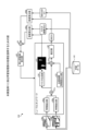
Next, an example of a system according to the third embodiment will be described. FIG. 19 is a diagram showing a system according to the third embodiment. As shown in FIG. 19, this system has a self-
ユーザ1は、仮置台6に置かれた商品2を手に取り、セルフレジ5に対して、商品2のバーコードをスキャンする操作を行い、包装するものとする。
The
セルフレジ5は、商品を購入するユーザ1が、商品のバーコードの読み取りから精算までを行うPOS(Point Of Sale)レジシステムである。たとえば、ユーザ1が、購入対象の商品を、セルフレジ5のスキャン領域に移動させると、セルフレジ5は、商品のバーコードをスキャンする。セルフレジ5は、ユーザ1によるスキャンが完了した際に、スキャンした商品の点数の情報を、情報処理装置300に通知する。以下の説明では、スキャンされた商品の点数の情報を、「スキャン情報」と表記する。
The self-
カメラ10は、セルフレジ5の仮置台6を撮影するカメラである。カメラ10は、撮影範囲の画像データを、情報処理装置300に送信する。カメラ10は、予め、商品が置かれていない仮置台6の画像データ(背景画像データ)を、情報処理装置300に送信しておくものとする。カメラ10は、仮置台6に購入対象となる商品が置かれた場合に、仮置台6の画像データ(対象画像データ)を、情報処理装置300に送信する。
The
情報処理装置300は、実施例1で説明した情報処理装置100と同様にして、ニューラルネットワークの機械学習を行っておく。ニューラルネットワークには、特徴抽出部50a,50b、合成部51a,51b、推定部52、位置座標特徴量出力部53、マスク生成部54が含まれる。
The
情報処理装置300は、背景画像データと、対象画像データとを機械学習済みのニューラルネットワークに入力することで、対象画像データに含まれる各物体を特定する。情報処理装置300は、特定した物体をカウントして、商品点数を特定する。情報処理装置300は、特定した商品点数と、スキャン情報に含まれる商品点数とが一致しない場合に、スキャン漏れを検出する。
The
たとえば、情報処理装置300は、背景画像データと、対象画像データとをニューラルネットワークに入力した結果を出力結果70とする。出力結果70には、BBOX70a,70b,70cの3つのBBOXが含まれているため、情報処理装置300は、商品点数を「3」として特定する。情報処理装置300は、スキャン情報に含まれる商品点数が「3」未満の場合には、スキャン漏れを検知する。情報処理装置300は、スキャン漏れを、図示しない管理サーバ等に通知してもよい。
For example, the
上記のように、実施例1,2で説明した情報処理装置100(200)を、図19に示すシステムに適用することで、バーコードの読み取りを行わない等のユーザの不正を検出することができる。 As described above, by applying the information processing device 100 (200) described in the first and second embodiments to the system shown in FIG. 19, it is possible to detect user fraud, such as not reading a barcode.
次に、上記実施例に示した情報処理装置100(200,300)と同様の機能を実現するコンピュータのハードウェア構成の一例について説明する。図20は、情報処理装置と同様の機能を実現するコンピュータのハードウェア構成の一例を示す図である。 Next, an example of the hardware configuration of a computer that realizes the same functions as the information processing device 100 (200, 300) shown in the above embodiment will be described. FIG. 20 is a diagram showing an example of the hardware configuration of a computer that realizes the same functions as the information processing device.
図20に示すように、コンピュータ400は、各種演算処理を実行するCPU401と、ユーザからのデータの入力を受け付ける入力装置402と、ディスプレイ403とを有する。また、コンピュータ400は、カメラ10から距離画像のデータを受信する通信装置404と、各種の装置と接続するインタフェース装置405とを有する。コンピュータ400は、各種情報を一時記憶するRAM406と、ハードディスク装置407とを有する。そして、各装置401~407は、バス408に接続される。
As shown in FIG. 20, the
ハードディスク装置407は、取得プログラム407a、学習処理プログラム407b、推論処理プログラム407cを有する。CPU401は、取得プログラム407a、学習処理プログラム407b、推論処理プログラム407cを読み出してRAM406に展開する。
The
取得プログラム407aは、取得プロセス406aとして機能する。学習処理プログラム407bは、学習処理プロセス406bとして機能する。推論処理プログラム407cは、推論処理プロセス406cとして機能する。
The
取得プロセス406aの処理は、取得部151,251の処理に対応する。学習処理プロセス406bの処理は、学習処理部152,252の処理に対応する。推論処理プロセス406cの処理は、推論処理部153,253の処理に対応する。
The processing of the
なお、各プログラム407a~407cについては、必ずしも最初からハードディスク装置407に記憶させておかなくてもよい。例えば、コンピュータ400に挿入されるフレキシブルディスク(FD)、CD-ROM、DVDディスク、光磁気ディスク、ICカードなどの「可搬用の物理媒体」に各プログラムを記憶させておく。そして、コンピュータ400が各プログラム407a~407cを読み出して実行するようにしてもよい。
Note that each of the
以上の各実施例を含む実施形態に関し、さらに以下の付記を開示する。 The following notes are further provided with respect to the embodiments including the above examples.
(付記1)物体を配置する対象のエリアが撮影された背景画像と、前記物体および前記エリアが撮影された対象画像とを取得し、
前記背景画像と、前記対象画像とを特徴抽出モデルに入力することで、中間特徴量を生成し、
前記中間特徴量を生成モデルに入力することで、前記背景画像には存在しないが前記対象画像には存在する物体の領域を示すマスク画像を生成し、
生成した前記マスク画像と前記中間特徴量とを推定モデルに入力することで、前記背景画像には存在しないが、前記対象画像には存在する物体を特定する
処理をコンピュータに実行させることを特徴とする推論プログラム。
(Supplementary Note 1) A background image in which a target area in which an object is to be placed is captured, and a target image in which the object and the target area are captured are obtained;
generating intermediate features by inputting the background image and the target image into a feature extraction model;
generating a mask image showing an area of an object that is not present in the background image but is present in the target image by inputting the intermediate features into a generative model;
The generated mask image and the intermediate feature amount are input to an estimation model, thereby causing a computer to execute a process of identifying an object that does not exist in the background image but exists in the target image.
(付記2)前記物体を特定する処理は、前記マスク画像と、前記中間特徴量と、座標値を画像平面状に配置した座標特徴量とを前記推定モデルに入力することで、前記物体を特定することを特徴とする付記1に記載の推論プログラム。
(Appendix 2) The inference program described in
(付記3)物体を配置する対象のエリアが撮影された背景画像と、前記物体および前記エリアが撮影された対象画像とを入力データとし、前記背景画像には存在しないが前記対象画像には存在する物体の領域と、前記対象画像に含まれる物体の位置とを正解データとする学習データを取得し、
前記学習データを基にして、前記背景画像および前記対象画像を入力することで、中間特徴量を出力する特徴抽出モデルと、前記中間特徴量を入力することで、前記背景画像には存在しないが前記対象画像には存在する物体の領域を示すマスク画像を出力する生成モデルと、前記マスク画像および前記中間特徴量を入力することで、前記背景画像には存在しないが、前記対象画像には存在する物体の位置を出力する推定モデルとに対する機械学習を実行する
処理をコンピュータに実行させることを特徴とする学習プログラム。
(Additional Note 3) A background image of a target area in which an object is to be placed and a target image of the object and the target area are taken as input data, and learning data is obtained in which an area of an object that does not exist in the background image but exists in the target image and a position of the object included in the target image are used as correct answer data;
a feature extraction model that outputs intermediate features by inputting the background image and the target image based on the learning data; a generation model that outputs a mask image showing an area of an object that does not exist in the background image but exists in the target image by inputting the intermediate features; and an estimation model that outputs a position of an object that does not exist in the background image but exists in the target image by inputting the mask image and the intermediate features.
(付記4)前記機械学習を実行する処理は、前記生成モデルから出力される物体の領域および前記正解データの物体の領域の差分と、前記推定モデルから出力される物体の位置および前記正解データの差分とが小さくなるように、前記特徴抽出モデルのパラメータ、前記生成モデルのパラメータ、前記推定モデルのパラメータを訓練することを特徴とする付記3に記載の学習プログラム。
(Appendix 4) The learning program described in
(付記5)前記機械学習を実行する処理は、前記マスク画像と、前記中間特徴量と、座標値を画像平面状に配置した座標特徴量とを前記推定モデルに入力して、機械学習を実行することを特徴とする付記3または4に記載の学習プログラム。
(Appendix 5) The learning program described in
(付記6)物体を配置する対象のエリアが撮影された背景画像と、前記物体および前記エリアが撮影された対象画像とを取得し、
前記背景画像と、前記対象画像とを特徴抽出モデルに入力することで、中間特徴量を生成し、
前記中間特徴量を生成モデルに入力することで、前記背景画像には存在しないが前記対象画像には存在する物体の領域を示すマスク画像を生成し、
生成した前記マスク画像と前記中間特徴量とを推定モデルに入力することで、前記背景画像には存在しないが、前記対象画像には存在する物体を特定する
処理をコンピュータが実行することを特徴とする推論方法。
(Supplementary Note 6) A background image in which a target area in which an object is to be placed is captured, and a target image in which the object and the target area are captured are obtained;
generating intermediate features by inputting the background image and the target image into a feature extraction model;
generating a mask image showing an area of an object that is not present in the background image but is present in the target image by inputting the intermediate features into a generative model;
The inference method is characterized in that a computer executes a process of identifying an object that does not exist in the background image but exists in the target image by inputting the generated mask image and the intermediate features into an estimation model.
(付記7)前記物体を特定する処理は、前記マスク画像と、前記中間特徴量と、座標値を画像平面状に配置した座標特徴量とを前記推定モデルに入力することで、前記物体を特定することを特徴とする付記6に記載の推論方法。
(Appendix 7) The inference method described in
(付記8)物体を配置する対象のエリアが撮影された背景画像と、前記物体および前記エリアが撮影された対象画像とを入力データとし、前記背景画像には存在しないが前記対象画像には存在する物体の領域と、前記対象画像に含まれる物体の位置とを正解データとする学習データを取得し、
前記学習データを基にして、前記背景画像および前記対象画像を入力することで、中間特徴量を出力する特徴抽出モデルと、前記中間特徴量を入力することで、前記背景画像には存在しないが前記対象画像には存在する物体の領域を示すマスク画像を出力する生成モデルと、前記マスク画像および前記中間特徴量を入力することで、前記背景画像には存在しないが、前記対象画像には存在する物体の位置を出力する推定モデルとに対する機械学習を実行する
処理をコンピュータが実行することを特徴とする学習方法。
(Supplementary Note 8) A background image of a target area in which an object is to be placed and a target image of the object and the target area are taken as input data, and learning data is obtained in which an area of an object that does not exist in the background image but exists in the target image and a position of the object included in the target image are used as correct answer data;
a feature extraction model that outputs intermediate features based on the learning data by inputting the background image and the target image, a generative model that outputs a mask image showing an area of an object that does not exist in the background image but exists in the target image by inputting the intermediate features, and an estimation model that outputs a position of an object that does not exist in the background image but exists in the target image by inputting the mask image and the intermediate features.
(付記9)前記機械学習を実行する処理は、前記生成モデルから出力される物体の領域および前記正解データの物体の領域の差分と、前記推定モデルから出力される物体の位置および前記正解データの差分とが小さくなるように、前記特徴抽出モデルのパラメータ、前記生成モデルのパラメータ、前記推定モデルのパラメータを訓練することを特徴とする付記8に記載の学習方法。
(Appendix 9) The learning method described in
(付記10)前記機械学習を実行する処理は、前記マスク画像と、前記中間特徴量と、座標値を画像平面状に配置した座標特徴量とを前記推定モデルに入力して、機械学習を実行することを特徴とする付記8または9に記載の学習方法。
(Appendix 10) The learning method described in
50a,50b 特徴抽出部
51a,51b,61 合成部
52 推定部
53 位置座標特徴量出力部
54 マスク生成部
60a,60b 誤差算出部
62 重み更新値算出部
100,200,300 情報処理装置
110,210 通信部
120,220 入力部
130,230 表示部
140,240 記憶部
141 学習データ
142 画像テーブル
143 特徴抽出モデル
144 生成モデル
145 推定モデル
150,250 制御部
151,251 取得部
152,252 学習処理部
153,253 推論処理部
50a, 50b Feature extraction unit 51a, 51b, 61
Claims (7)
前記背景画像と、前記対象画像とを特徴抽出モデルに入力することで、中間特徴量を生成し、
前記中間特徴量を生成モデルに入力することで、前記背景画像には存在しないが前記対象画像には存在する物体の領域を示すマスク画像を生成し、
生成した前記マスク画像と前記中間特徴量とを推定モデルに入力することで、前記背景画像には存在しないが、前記対象画像には存在する物体を特定する
処理をコンピュータに実行させることを特徴とする推論プログラム。 Obtaining a background image of an area to be targeted for placement of an object and a target image of the object and the area;
generating intermediate features by inputting the background image and the target image into a feature extraction model;
generating a mask image showing an area of an object that is not present in the background image but is present in the target image by inputting the intermediate features into a generative model;
The generated mask image and the intermediate feature amount are input to an estimation model, thereby causing a computer to execute a process of identifying an object that does not exist in the background image but exists in the target image.
前記学習データを基にして、前記背景画像および前記対象画像を入力することで、中間特徴量を出力する特徴抽出モデルと、前記中間特徴量を入力することで、前記背景画像には存在しないが前記対象画像には存在する物体の領域を示すマスク画像を出力する生成モデルと、前記マスク画像および前記中間特徴量を入力することで、前記背景画像には存在しないが、前記対象画像には存在する物体の位置を出力する推定モデルとに対する機械学習を実行する
処理をコンピュータに実行させることを特徴とする学習プログラム。 A background image of a target area in which an object is to be placed and a target image of the object and the target area are taken as input data, and learning data is obtained in which an area of an object that does not exist in the background image but exists in the target image and a position of the object included in the target image are used as correct answer data;
a feature extraction model that outputs intermediate features by inputting the background image and the target image based on the learning data; a generation model that outputs a mask image showing an area of an object that does not exist in the background image but exists in the target image by inputting the intermediate features; and an estimation model that outputs a position of an object that does not exist in the background image but exists in the target image by inputting the mask image and the intermediate features.
前記背景画像と、前記対象画像とを特徴抽出モデルに入力することで、中間特徴量を生成し、
前記中間特徴量を生成モデルに入力することで、前記背景画像には存在しないが前記対象画像には存在する物体の領域を示すマスク画像を生成し、
生成した前記マスク画像と前記中間特徴量とを推定モデルに入力することで、前記背景画像には存在しないが、前記対象画像には存在する物体を特定する
処理をコンピュータが実行することを特徴とする推論方法。 Obtaining a background image of an area to be targeted for placement of an object and a target image of the object and the area;
generating intermediate features by inputting the background image and the target image into a feature extraction model;
generating a mask image showing an area of an object that is not present in the background image but is present in the target image by inputting the intermediate features into a generative model;
The inference method is characterized in that a computer executes a process of identifying an object that does not exist in the background image but exists in the target image by inputting the generated mask image and the intermediate features into an estimation model.
前記学習データを基にして、前記背景画像および前記対象画像を入力することで、中間特徴量を出力する特徴抽出モデルと、前記中間特徴量を入力することで、前記背景画像には存在しないが前記対象画像には存在する物体の領域を示すマスク画像を出力する生成モデルと、前記マスク画像および前記中間特徴量を入力することで、前記背景画像には存在しないが、前記対象画像には存在する物体の位置を出力する推定モデルとに対する機械学習を実行する
処理をコンピュータが実行することを特徴とする学習方法。 A background image of a target area in which an object is to be placed and a target image of the object and the target area are taken as input data, and learning data is obtained in which an area of an object that does not exist in the background image but exists in the target image and a position of the object included in the target image are used as correct answer data;
a feature extraction model that outputs intermediate features based on the learning data by inputting the background image and the target image, a generative model that outputs a mask image showing an area of an object that does not exist in the background image but exists in the target image by inputting the intermediate features, and an estimation model that outputs a position of an object that does not exist in the background image but exists in the target image by inputting the mask image and the intermediate features.
Priority Applications (4)
| Application Number | Priority Date | Filing Date | Title |
|---|---|---|---|
| JP2021174706A JP7687186B2 (en) | 2021-10-26 | 2021-10-26 | Inference program, learning program, inference method, and learning method |
| EP22182201.8A EP4174796A1 (en) | 2021-10-26 | 2022-06-30 | Inference program, learning program, inference method, and learning method |
| US17/857,087 US12236674B2 (en) | 2021-10-26 | 2022-07-04 | Computer-readable recording medium storing inference program, computer-readable recording medium storing learning program, inference method, and learning method |
| KR1020220090199A KR102891871B1 (en) | 2021-10-26 | 2022-07-21 | Inference program, learning program, inference method, and learning method |
Applications Claiming Priority (1)
| Application Number | Priority Date | Filing Date | Title |
|---|---|---|---|
| JP2021174706A JP7687186B2 (en) | 2021-10-26 | 2021-10-26 | Inference program, learning program, inference method, and learning method |
Publications (2)
| Publication Number | Publication Date |
|---|---|
| JP2023064427A JP2023064427A (en) | 2023-05-11 |
| JP7687186B2 true JP7687186B2 (en) | 2025-06-03 |
Family
ID=82492479
Family Applications (1)
| Application Number | Title | Priority Date | Filing Date |
|---|---|---|---|
| JP2021174706A Active JP7687186B2 (en) | 2021-10-26 | 2021-10-26 | Inference program, learning program, inference method, and learning method |
Country Status (4)
| Country | Link |
|---|---|
| US (1) | US12236674B2 (en) |
| EP (1) | EP4174796A1 (en) |
| JP (1) | JP7687186B2 (en) |
| KR (1) | KR102891871B1 (en) |
Families Citing this family (1)
| Publication number | Priority date | Publication date | Assignee | Title |
|---|---|---|---|---|
| US11928660B2 (en) * | 2022-03-18 | 2024-03-12 | Toshiba Global Commerce Solutions Holdings Corporation | Scanner swipe guidance system |
Citations (3)
| Publication number | Priority date | Publication date | Assignee | Title |
|---|---|---|---|---|
| JP2021082155A (en) | 2019-11-21 | 2021-05-27 | オムロン株式会社 | Model generating device, estimating device, model generating method, and model generating program |
| WO2021189641A1 (en) | 2020-03-25 | 2021-09-30 | 上海商汤临港智能科技有限公司 | Left-behind subject detection |
| US20210314531A1 (en) | 2018-12-27 | 2021-10-07 | World Cns, Inc. | Image survellance apparatus applied with moving-path tracking technique using multi camera |
Family Cites Families (14)
| Publication number | Priority date | Publication date | Assignee | Title |
|---|---|---|---|---|
| JP4623387B2 (en) | 2008-09-04 | 2011-02-02 | ソニー株式会社 | Learning device and method, recognition device and method, and program |
| GB2476258A (en) * | 2009-12-16 | 2011-06-22 | Thales Holdings Uk Plc | Motion detection using histogram analysis |
| JP5701005B2 (en) * | 2010-10-15 | 2015-04-15 | キヤノン株式会社 | Object detection apparatus, object detection method, surveillance camera system, and program |
| US9158971B2 (en) | 2014-03-03 | 2015-10-13 | Xerox Corporation | Self-learning object detectors for unlabeled videos using multi-task learning |
| US11568627B2 (en) * | 2015-11-18 | 2023-01-31 | Adobe Inc. | Utilizing interactive deep learning to select objects in digital visual media |
| JP7191088B2 (en) * | 2017-08-07 | 2022-12-16 | スタンダード コグニション コーポレーション | Predicting inventory events using semantic differencing |
| US10628109B2 (en) * | 2017-08-09 | 2020-04-21 | Google Llc | Dynamically adapting panels of a user interface |
| JP2019153057A (en) | 2018-03-02 | 2019-09-12 | 富士通株式会社 | Image processing apparatus, learning apparatus, image processing method, learning method, image processing program, and learning program |
| JP7313828B2 (en) | 2019-01-22 | 2023-07-25 | キヤノン株式会社 | Information processing device, information processing method, and program |
| US11158055B2 (en) * | 2019-07-26 | 2021-10-26 | Adobe Inc. | Utilizing a neural network having a two-stream encoder architecture to generate composite digital images |
| US11551429B2 (en) * | 2020-06-05 | 2023-01-10 | Uatc, Llc | Photorealistic image simulation with geometry-aware composition |
| US11276177B1 (en) * | 2020-10-05 | 2022-03-15 | Qualcomm Incorporated | Segmentation for image effects |
| US11972569B2 (en) * | 2021-01-26 | 2024-04-30 | Adobe Inc. | Segmenting objects in digital images utilizing a multi-object segmentation model framework |
| US12148074B2 (en) * | 2021-10-18 | 2024-11-19 | Adobe Inc. | Object-to-object harmonization for digital images |
-
2021
- 2021-10-26 JP JP2021174706A patent/JP7687186B2/en active Active
-
2022
- 2022-06-30 EP EP22182201.8A patent/EP4174796A1/en active Pending
- 2022-07-04 US US17/857,087 patent/US12236674B2/en active Active
- 2022-07-21 KR KR1020220090199A patent/KR102891871B1/en active Active
Patent Citations (4)
| Publication number | Priority date | Publication date | Assignee | Title |
|---|---|---|---|---|
| US20210314531A1 (en) | 2018-12-27 | 2021-10-07 | World Cns, Inc. | Image survellance apparatus applied with moving-path tracking technique using multi camera |
| JP2021082155A (en) | 2019-11-21 | 2021-05-27 | オムロン株式会社 | Model generating device, estimating device, model generating method, and model generating program |
| WO2021189641A1 (en) | 2020-03-25 | 2021-09-30 | 上海商汤临港智能科技有限公司 | Left-behind subject detection |
| JP2022530299A (en) | 2020-03-25 | 2022-06-29 | 上海商▲湯▼▲臨▼港智能科技有限公司 | Detection of residual targets |
Non-Patent Citations (1)
| Title |
|---|
| Jifeng Dai et al.,Instance-Aware Semantic Segmentation via Multi-task Network Cascades,2016 IEEE Conference on Computer Vision and Pattern Recognition (CVPR),米国,IEEE,2016年06月30日,pp.3150-3158,https://ieeexplore.ieee.org/stamp/stamp.jsp?tp=&arnumber=7780712 |
Also Published As
| Publication number | Publication date |
|---|---|
| US20230127469A1 (en) | 2023-04-27 |
| US12236674B2 (en) | 2025-02-25 |
| EP4174796A1 (en) | 2023-05-03 |
| KR20230059712A (en) | 2023-05-03 |
| JP2023064427A (en) | 2023-05-11 |
| KR102891871B1 (en) | 2025-11-27 |
Similar Documents
| Publication | Publication Date | Title |
|---|---|---|
| CN101251897A (en) | Image processing device, image processing method, and program | |
| JP7081310B2 (en) | Behavioral analytics device, behavioral analytics system, behavioral analytics method, program and recording medium | |
| WO2017198749A1 (en) | Image processing apparatus and method | |
| JP7764726B2 (en) | Learning program, learning method, and information processing device | |
| US20240193993A1 (en) | Non-transitory computer-readable recording medium, information processing method, and information processing apparatus | |
| JP2022176481A (en) | Identification program, identification method and information processing device | |
| JP2023050597A (en) | Notification program, notification method and information processing device | |
| JP7687186B2 (en) | Inference program, learning program, inference method, and learning method | |
| JP7688289B2 (en) | DECISION MODEL GENERATION METHOD, INFORMATION PROCESSING APPARATUS, AND DECISION MODEL GENERATION PROGRAM | |
| TWI734054B (en) | Information processing apparatus, display position adjusting method, and storage medium | |
| JP7211455B2 (en) | Processing system, processing method and program | |
| JP2017162098A (en) | Learning method, information processing device and learning program | |
| EP4160533B1 (en) | Estimation program, estimation method, and estimation device | |
| US20230351412A1 (en) | Information processing apparatus, information processing method, information processing program, and information processing system | |
| EP4125056A1 (en) | Information processing program, information processing method, and information processing device | |
| JP6769555B2 (en) | Article identification device, article identification method, calculation device, system and program | |
| JP2023153316A (en) | Processing equipment, processing method and program | |
| CN114694263A (en) | Action recognition method, device, equipment and storage medium | |
| CN116745808A (en) | Job estimation device, job estimation method and job estimation program | |
| JP7578205B2 (en) | Processing system, processing method, and program | |
| WO2023175767A1 (en) | Product confirmation device, product confirmation method, and recording medium | |
| JP2024176134A (en) | Information processing program, information processing method, and information processing device | |
| JP2024089579A (en) | ALERT OUTPUT PROGRAM, ALERT OUTPUT METHOD, AND INFORMATION PROCESSING APPARATUS | |
| WO2023188068A1 (en) | Product quantity identification device, product quantity identification method, and recording medium | |
| JP2023051360A (en) | Information processing program, information processing method and information processor |
Legal Events
| Date | Code | Title | Description |
|---|---|---|---|
| A621 | Written request for application examination |
Free format text: JAPANESE INTERMEDIATE CODE: A621 Effective date: 20240711 |
|
| A977 | Report on retrieval |
Free format text: JAPANESE INTERMEDIATE CODE: A971007 Effective date: 20250327 |
|
| TRDD | Decision of grant or rejection written | ||
| A01 | Written decision to grant a patent or to grant a registration (utility model) |
Free format text: JAPANESE INTERMEDIATE CODE: A01 Effective date: 20250422 |
|
| A61 | First payment of annual fees (during grant procedure) |
Free format text: JAPANESE INTERMEDIATE CODE: A61 Effective date: 20250505 |
|
| R150 | Certificate of patent or registration of utility model |
Ref document number: 7687186 Country of ref document: JP Free format text: JAPANESE INTERMEDIATE CODE: R150 |