JP7686630B2 - Method for controlling the lateral position of a motor vehicle - Patents.com - Google Patents
Method for controlling the lateral position of a motor vehicle - Patents.com Download PDFInfo
- Publication number
- JP7686630B2 JP7686630B2 JP2022517326A JP2022517326A JP7686630B2 JP 7686630 B2 JP7686630 B2 JP 7686630B2 JP 2022517326 A JP2022517326 A JP 2022517326A JP 2022517326 A JP2022517326 A JP 2022517326A JP 7686630 B2 JP7686630 B2 JP 7686630B2
- Authority
- JP
- Japan
- Prior art keywords
- vehicle
- motor vehicle
- distance
- component
- calculating
- Prior art date
- Legal status (The legal status is an assumption and is not a legal conclusion. Google has not performed a legal analysis and makes no representation as to the accuracy of the status listed.)
- Active
Links
Images


Classifications
-
- B—PERFORMING OPERATIONS; TRANSPORTING
- B62—LAND VEHICLES FOR TRAVELLING OTHERWISE THAN ON RAILS
- B62D—MOTOR VEHICLES; TRAILERS
- B62D15/00—Steering not otherwise provided for
- B62D15/02—Steering position indicators ; Steering position determination; Steering aids
- B62D15/025—Active steering aids, e.g. helping the driver by actively influencing the steering system after environment evaluation
-
- B—PERFORMING OPERATIONS; TRANSPORTING
- B60—VEHICLES IN GENERAL
- B60W—CONJOINT CONTROL OF VEHICLE SUB-UNITS OF DIFFERENT TYPE OR DIFFERENT FUNCTION; CONTROL SYSTEMS SPECIALLY ADAPTED FOR HYBRID VEHICLES; ROAD VEHICLE DRIVE CONTROL SYSTEMS FOR PURPOSES NOT RELATED TO THE CONTROL OF A PARTICULAR SUB-UNIT
- B60W30/00—Purposes of road vehicle drive control systems not related to the control of a particular sub-unit, e.g. of systems using conjoint control of vehicle sub-units
- B60W30/02—Control of vehicle driving stability
- B60W30/045—Improving turning performance
-
- B—PERFORMING OPERATIONS; TRANSPORTING
- B60—VEHICLES IN GENERAL
- B60W—CONJOINT CONTROL OF VEHICLE SUB-UNITS OF DIFFERENT TYPE OR DIFFERENT FUNCTION; CONTROL SYSTEMS SPECIALLY ADAPTED FOR HYBRID VEHICLES; ROAD VEHICLE DRIVE CONTROL SYSTEMS FOR PURPOSES NOT RELATED TO THE CONTROL OF A PARTICULAR SUB-UNIT
- B60W30/00—Purposes of road vehicle drive control systems not related to the control of a particular sub-unit, e.g. of systems using conjoint control of vehicle sub-units
- B60W30/10—Path keeping
- B60W30/12—Lane keeping
-
- B—PERFORMING OPERATIONS; TRANSPORTING
- B60—VEHICLES IN GENERAL
- B60W—CONJOINT CONTROL OF VEHICLE SUB-UNITS OF DIFFERENT TYPE OR DIFFERENT FUNCTION; CONTROL SYSTEMS SPECIALLY ADAPTED FOR HYBRID VEHICLES; ROAD VEHICLE DRIVE CONTROL SYSTEMS FOR PURPOSES NOT RELATED TO THE CONTROL OF A PARTICULAR SUB-UNIT
- B60W40/00—Estimation or calculation of non-directly measurable driving parameters for road vehicle drive control systems not related to the control of a particular sub unit, e.g. by using mathematical models
- B60W40/10—Estimation or calculation of non-directly measurable driving parameters for road vehicle drive control systems not related to the control of a particular sub unit, e.g. by using mathematical models related to vehicle motion
- B60W40/109—Lateral acceleration
-
- B—PERFORMING OPERATIONS; TRANSPORTING
- B60—VEHICLES IN GENERAL
- B60W—CONJOINT CONTROL OF VEHICLE SUB-UNITS OF DIFFERENT TYPE OR DIFFERENT FUNCTION; CONTROL SYSTEMS SPECIALLY ADAPTED FOR HYBRID VEHICLES; ROAD VEHICLE DRIVE CONTROL SYSTEMS FOR PURPOSES NOT RELATED TO THE CONTROL OF A PARTICULAR SUB-UNIT
- B60W50/00—Details of control systems for road vehicle drive control not related to the control of a particular sub-unit, e.g. process diagnostic or vehicle driver interfaces
-
- B—PERFORMING OPERATIONS; TRANSPORTING
- B62—LAND VEHICLES FOR TRAVELLING OTHERWISE THAN ON RAILS
- B62D—MOTOR VEHICLES; TRAILERS
- B62D15/00—Steering not otherwise provided for
- B62D15/02—Steering position indicators ; Steering position determination; Steering aids
- B62D15/021—Determination of steering angle
-
- B—PERFORMING OPERATIONS; TRANSPORTING
- B62—LAND VEHICLES FOR TRAVELLING OTHERWISE THAN ON RAILS
- B62D—MOTOR VEHICLES; TRAILERS
- B62D6/00—Arrangements for automatically controlling steering depending on driving conditions sensed and responded to, e.g. control circuits
- B62D6/001—Arrangements for automatically controlling steering depending on driving conditions sensed and responded to, e.g. control circuits the torque NOT being among the input parameters
-
- B—PERFORMING OPERATIONS; TRANSPORTING
- B60—VEHICLES IN GENERAL
- B60W—CONJOINT CONTROL OF VEHICLE SUB-UNITS OF DIFFERENT TYPE OR DIFFERENT FUNCTION; CONTROL SYSTEMS SPECIALLY ADAPTED FOR HYBRID VEHICLES; ROAD VEHICLE DRIVE CONTROL SYSTEMS FOR PURPOSES NOT RELATED TO THE CONTROL OF A PARTICULAR SUB-UNIT
- B60W50/00—Details of control systems for road vehicle drive control not related to the control of a particular sub-unit, e.g. process diagnostic or vehicle driver interfaces
- B60W2050/0001—Details of the control system
- B60W2050/0002—Automatic control, details of type of controller or control system architecture
- B60W2050/0008—Feedback, closed loop systems or details of feedback error signal
-
- B—PERFORMING OPERATIONS; TRANSPORTING
- B60—VEHICLES IN GENERAL
- B60W—CONJOINT CONTROL OF VEHICLE SUB-UNITS OF DIFFERENT TYPE OR DIFFERENT FUNCTION; CONTROL SYSTEMS SPECIALLY ADAPTED FOR HYBRID VEHICLES; ROAD VEHICLE DRIVE CONTROL SYSTEMS FOR PURPOSES NOT RELATED TO THE CONTROL OF A PARTICULAR SUB-UNIT
- B60W50/00—Details of control systems for road vehicle drive control not related to the control of a particular sub-unit, e.g. process diagnostic or vehicle driver interfaces
- B60W2050/0001—Details of the control system
- B60W2050/0002—Automatic control, details of type of controller or control system architecture
- B60W2050/0012—Feedforward or open loop systems
-
- B—PERFORMING OPERATIONS; TRANSPORTING
- B60—VEHICLES IN GENERAL
- B60W—CONJOINT CONTROL OF VEHICLE SUB-UNITS OF DIFFERENT TYPE OR DIFFERENT FUNCTION; CONTROL SYSTEMS SPECIALLY ADAPTED FOR HYBRID VEHICLES; ROAD VEHICLE DRIVE CONTROL SYSTEMS FOR PURPOSES NOT RELATED TO THE CONTROL OF A PARTICULAR SUB-UNIT
- B60W50/00—Details of control systems for road vehicle drive control not related to the control of a particular sub-unit, e.g. process diagnostic or vehicle driver interfaces
- B60W2050/0001—Details of the control system
- B60W2050/0002—Automatic control, details of type of controller or control system architecture
- B60W2050/0014—Adaptive controllers
-
- B—PERFORMING OPERATIONS; TRANSPORTING
- B60—VEHICLES IN GENERAL
- B60W—CONJOINT CONTROL OF VEHICLE SUB-UNITS OF DIFFERENT TYPE OR DIFFERENT FUNCTION; CONTROL SYSTEMS SPECIALLY ADAPTED FOR HYBRID VEHICLES; ROAD VEHICLE DRIVE CONTROL SYSTEMS FOR PURPOSES NOT RELATED TO THE CONTROL OF A PARTICULAR SUB-UNIT
- B60W50/00—Details of control systems for road vehicle drive control not related to the control of a particular sub-unit, e.g. process diagnostic or vehicle driver interfaces
- B60W2050/0001—Details of the control system
- B60W2050/0002—Automatic control, details of type of controller or control system architecture
- B60W2050/0018—Method for the design of a control system
-
- B—PERFORMING OPERATIONS; TRANSPORTING
- B60—VEHICLES IN GENERAL
- B60W—CONJOINT CONTROL OF VEHICLE SUB-UNITS OF DIFFERENT TYPE OR DIFFERENT FUNCTION; CONTROL SYSTEMS SPECIALLY ADAPTED FOR HYBRID VEHICLES; ROAD VEHICLE DRIVE CONTROL SYSTEMS FOR PURPOSES NOT RELATED TO THE CONTROL OF A PARTICULAR SUB-UNIT
- B60W50/00—Details of control systems for road vehicle drive control not related to the control of a particular sub-unit, e.g. process diagnostic or vehicle driver interfaces
- B60W2050/0062—Adapting control system settings
- B60W2050/0075—Automatic parameter input, automatic initialising or calibrating means
- B60W2050/0082—Automatic parameter input, automatic initialising or calibrating means for initialising the control system
-
- B—PERFORMING OPERATIONS; TRANSPORTING
- B60—VEHICLES IN GENERAL
- B60W—CONJOINT CONTROL OF VEHICLE SUB-UNITS OF DIFFERENT TYPE OR DIFFERENT FUNCTION; CONTROL SYSTEMS SPECIALLY ADAPTED FOR HYBRID VEHICLES; ROAD VEHICLE DRIVE CONTROL SYSTEMS FOR PURPOSES NOT RELATED TO THE CONTROL OF A PARTICULAR SUB-UNIT
- B60W50/00—Details of control systems for road vehicle drive control not related to the control of a particular sub-unit, e.g. process diagnostic or vehicle driver interfaces
- B60W2050/0062—Adapting control system settings
- B60W2050/0075—Automatic parameter input, automatic initialising or calibrating means
- B60W2050/0083—Setting, resetting, calibration
-
- B—PERFORMING OPERATIONS; TRANSPORTING
- B60—VEHICLES IN GENERAL
- B60W—CONJOINT CONTROL OF VEHICLE SUB-UNITS OF DIFFERENT TYPE OR DIFFERENT FUNCTION; CONTROL SYSTEMS SPECIALLY ADAPTED FOR HYBRID VEHICLES; ROAD VEHICLE DRIVE CONTROL SYSTEMS FOR PURPOSES NOT RELATED TO THE CONTROL OF A PARTICULAR SUB-UNIT
- B60W2520/00—Input parameters relating to overall vehicle dynamics
- B60W2520/12—Lateral speed
- B60W2520/125—Lateral acceleration
-
- B—PERFORMING OPERATIONS; TRANSPORTING
- B60—VEHICLES IN GENERAL
- B60W—CONJOINT CONTROL OF VEHICLE SUB-UNITS OF DIFFERENT TYPE OR DIFFERENT FUNCTION; CONTROL SYSTEMS SPECIALLY ADAPTED FOR HYBRID VEHICLES; ROAD VEHICLE DRIVE CONTROL SYSTEMS FOR PURPOSES NOT RELATED TO THE CONTROL OF A PARTICULAR SUB-UNIT
- B60W2710/00—Output or target parameters relating to a particular sub-units
- B60W2710/20—Steering systems
- B60W2710/207—Steering angle of wheels
Landscapes
- Engineering & Computer Science (AREA)
- Transportation (AREA)
- Mechanical Engineering (AREA)
- Automation & Control Theory (AREA)
- Chemical & Material Sciences (AREA)
- Combustion & Propulsion (AREA)
- Human Computer Interaction (AREA)
- Physics & Mathematics (AREA)
- Mathematical Physics (AREA)
- Steering Control In Accordance With Driving Conditions (AREA)
- Control Of Driving Devices And Active Controlling Of Vehicle (AREA)
Description
本発明は、モータ車両の、とりわけ、運転者支援システムを装備された車両の、横方向位置を制御するための方法に関する。本発明は、さらには、そのような方法を実行するハードウェアおよび/またはソフトウェア手段を含むモータ車両に関する。本発明は、最後に、そのような車両を較正するための方法に関する。 The present invention relates to a method for controlling the lateral position of a motor vehicle, in particular a vehicle equipped with a driver assistance system. The present invention further relates to a motor vehicle including hardware and/or software means for carrying out such a method. The present invention finally relates to a method for calibrating such a vehicle.
運転者支援システムを装備された車両は、一般的には、コンピュータ制御される操舵システムを含む。操舵システムは、車両が所与の軌道に追従するように、車両の被操舵輪の向きを制御する。コンピュータは、交通車線上で車両を横方向に位置決めすることを可能にする制御方法を実行する。とりわけ、コンピュータは、車両を、その車両の交通車線の中心に保つことを可能にする、LCA(車線センタリング支援(lane centering assist))と呼ばれる制御方法を実行することができる。 Vehicles equipped with driver assistance systems typically include a computer-controlled steering system. The steering system controls the orientation of the vehicle's steered wheels so that the vehicle follows a given trajectory. The computer implements control methods that allow the vehicle to be positioned laterally on a traffic lane. In particular, the computer can implement a control method called LCA (lane centering assist), which allows the vehicle to be kept in the center of its traffic lane.
そのような制御方法は、車両が、所与の軌道に沿って、徐々に、および、ジャークなしに操舵されることを可能とすることを必要とする。しかしながら、現況技術から知られている車両により実施される制御の品質は、車両の状態、および/または、外側コンディションが変動するときに低下させられるということが見出されている。とりわけ、車両の荷重、その車両の重心の位置、その車両のタイヤの状態、または、使用されるタイヤのタイプが、とりわけ転回を行うときに、車両の動的挙動に影響する。制御方法の実行を基に算出される操舵角度セットポイントは、計画された軌道とは有意に異なる軌道につながることがある。車両の横方向位置を補正する移動が、次いで生じる。これらの補正移動は、とりわけ、遅れたものであり、不適切でさえあり、車両の乗り手に対して不快感を生み出すことがある。それゆえに、車両の状態が変更される場合のみならず、例えば、道路グリップの変移、および/または、風の力もしくは方向の変化など、車両の外側のコンディションが変動する場合にも性能低下が感じられることがある。 Such a control method should enable the vehicle to be steered gradually and without jerks along a given trajectory. However, it has been found that the quality of control performed by vehicles known from the state of the art is degraded when the state of the vehicle and/or the external conditions vary. In particular, the load of the vehicle, the position of the center of gravity of the vehicle, the state of the tires of the vehicle or the type of tires used influence the dynamic behavior of the vehicle, in particular when performing turns. The steering angle set point calculated on the basis of the execution of the control method may lead to a trajectory that differs significantly from the planned trajectory. Corrective movements of the lateral position of the vehicle are then produced. These corrective movements may, in particular, be delayed or even inappropriate and may generate discomfort for the vehicle's rider. Therefore, a performance degradation may be felt not only when the state of the vehicle is changed, but also when the conditions outside the vehicle vary, such as, for example, a shift in road grip and/or a change in wind force or direction.
制御則を適合させるために、車両状態センサの使用に頼る、被操舵輪の操舵角度セットポイントを算出するための方法が知られている。しかしながら、車両の動的挙動を乱す要因を識別することは、複雑および困難なままである。さらにまた、そのようなセンサは、車両内に組み込むには複雑である。これらの方法は、それゆえに、実行するには複雑であり、車両により経験される横方向加速度を完全に克服することを可能にしない。 Methods are known for calculating the steering angle setpoints of the steered wheels that rely on the use of vehicle state sensors to adapt the control law. However, identifying factors that disturb the dynamic behavior of the vehicle remains complex and difficult. Furthermore, such sensors are complex to integrate within the vehicle. These methods are therefore complex to implement and do not allow to fully overcome the lateral acceleration experienced by the vehicle.
発明の概観
本発明の目標は、上記の欠点を直す、および、従来技術から知られている制御方法を改善する、モータ車両の横方向位置を制御するための方法を提供することである。
Overview of the invention The aim of the present invention is to provide a method for controlling the lateral position of a motor vehicle, which remedies the above mentioned drawbacks and improves upon the control methods known from the prior art.
より具体的には、本発明の第1の主題は、車両の状態に、または、車両の外側のコンディションに、より非依存的である、モータ車両の横方向位置を制御するための方法である。 More specifically, the first subject of the invention is a method for controlling the lateral position of a motor vehicle that is more independent of the state of the vehicle or of conditions external to the vehicle.
本発明の第2の主題は、車両の状態に、および/または、車両の外側のコンディションに、より非依存的であるのみならず、車両状態センサの使用、もしくは、車両の外側のコンディションのセンサの使用を、または、車両の動的挙動を変移させる要因の識別さえも要さない、モータ車両の横方向位置を制御するための方法である。 The second subject of the invention is a method for controlling the lateral position of a motor vehicle that is not only more independent of the state of the vehicle and/or of the conditions outside the vehicle, but also does not require the use of vehicle state sensors or sensors of the conditions outside the vehicle or even the identification of factors that alter the dynamic behavior of the vehicle.
本発明は、モータ車両の横方向位置を制御するための方法であって、
- 車両内に設置される検出手段の注目距離(distance de visee)を算出するステップと、
- 車両の被操舵輪の操舵角度セットポイントの第1の構成要素を算出するステップであって、第1の構成要素は、制御システムの開ループ構成要素であり、第1の構成要素は、利得により重み付けされ、前記利得は、注目距離の減少関数である、第1の構成要素を算出するステップと、
- 前記操舵角度セットポイントの第2の構成要素を算出するステップであって、第2の構成要素は、制御システムの閉ループ構成要素である、第2の構成要素を算出するステップと
を含む、方法に関する。
The present invention relates to a method for controlling a lateral position of a motor vehicle, the method comprising:
- calculating the distance of interest of the detection means installed in the vehicle;
- calculating a first component of a steering angle setpoint of the steered wheels of the vehicle, the first component being an open loop component of the control system, the first component being weighted by a gain, said gain being a decreasing function of the distance of interest;
- calculating a second component of said steering angle setpoint, which second component is a closed-loop component of a control system.
前記利得は、0以上1以下であり得る。 The gain can be greater than or equal to 0 and less than or equal to 1.
前記利得は、注目距離の減少線形関数であり得、および/または、前記利得は、注目距離が0であるときに1に等しくあり得る。 The gain may be a decreasing linear function of the attention distance and/or the gain may be equal to 1 when the attention distance is 0.
制御方法は、操舵角度セットポイントを算出するステップであって、操舵角度セットポイントは、開ループ構成要素と閉ループ構成要素の総和に等しい、操舵角度セットポイントを算出するステップを含むことができる。 The control method may include calculating a steering angle setpoint, the steering angle setpoint being equal to the sum of an open loop component and a closed loop component.
第2の構成要素を算出するステップは、車両の状態ベクトルを算出するサブステップであって、状態ベクトルは、注目距離における基準軌道についての車両の横方向ずれに等しい構成要素を含む、車両の状態ベクトルを算出するサブステップを含むことができる。 The step of calculating the second component may include a substep of calculating a state vector of the vehicle, the state vector including a component equal to a lateral deviation of the vehicle relative to a reference trajectory at a distance of interest.
前記操舵角度セットポイントの第2の構成要素を算出するステップは、注目距離における車両の横方向ずれに注目距離を乗算するサブステップを含むことができる。 The step of calculating the second component of the steering angle set point may include a substep of multiplying the lateral deviation of the vehicle at the distance of interest by the distance of interest.
制御方法は、
- 車両の将来横方向加速度を算出するステップと、
- 横方向加速度を、しきい値と比較するステップと、次いで、
- 横方向加速度がしきい値以上である場合、前記操舵角度セットポイントの第1の構成要素を算出するステップであって、第1の構成要素は、注目距離に依存しない所定の値に等しい利得により重み付けされる、第1の構成要素を算出するステップと、
- 横方向加速度が厳密にしきい値未満である場合、前記操舵角度セットポイントの第1の構成要素を算出するステップであって、第1の構成要素は、利得により重み付けされ、前記利得は、注目距離の減少関数である、第1の構成要素を算出するステップと
を含むことができる。
The control method is
- calculating a future lateral acceleration of the vehicle;
- comparing the lateral acceleration with a threshold value, then
- if the lateral acceleration is greater than or equal to a threshold value, calculating a first component of said steering angle setpoint, the first component being weighted by a gain equal to a predetermined value independent of the distance of interest;
if the lateral acceleration is strictly below a threshold, calculating a first component of the steering angle setpoint, the first component being weighted by a gain, the gain being a decreasing function of a distance of interest.
車両の将来横方向加速度を算出するステップは、ナビゲーションシステムを用いて交通車線の曲率を取得するサブステップを含むことができる。 The step of calculating the vehicle's future lateral acceleration may include a substep of obtaining the curvature of the traffic lane using a navigation system.
注目距離を算出するステップは、所定の距離と、車両の検出手段の視界到達範囲(portee de vue)との間の最小値の選択を含むことができる。 The step of calculating the attention distance may include selecting the minimum between the predetermined distance and the portee de vue of the vehicle's detection means.
本発明は、さらには、媒体上に記憶される、プログラムコード命令を含むコンピュータプログラム製品であって、前記プログラムを電子制御ユニット上で実行するときに、先に定義されたような制御方法のステップを実行するために電子制御ユニットにより読み出すことのできる、コンピュータプログラム製品に関する。 The invention further relates to a computer program product comprising program code instructions stored on a medium, which can be read by an electronic control unit to execute the steps of a control method as defined above, when said program is executed on the electronic control unit.
本発明は、さらには、通信ネットワークからダウンロードされ、および/もしくは、コンピュータ可読データ媒体上に記憶され得る、ならびに/または、コンピュータにより実行され得る、コンピュータプログラム製品であって、プログラムがコンピュータにより走らされるときに、先に定義されたような制御方法を実行することをそのコンピュータに行わせる命令を含む、コンピュータプログラム製品に関する。 The invention further relates to a computer program product, which can be downloaded from a communications network and/or stored on a computer-readable data medium and/or executed by a computer, comprising instructions which, when the program is run by a computer, cause the computer to carry out a control method as defined above.
本発明は、さらには、先に定義されたような制御方法を実現するためのプログラムコード命令を含むコンピュータプログラムが記憶される、電子制御ユニットにより読み出すことのできる、データ記憶媒体に関する。 The invention further relates to a data storage medium, readable by an electronic control unit, on which a computer program is stored, the computer program comprising program code instructions for implementing the control method as defined above.
本発明は、さらには、命令であって、それらの命令がコンピュータにより実行されるときに、先に定義されたような制御方法を実行することをそのコンピュータに行わせる、命令を含む、コンピュータ可読記憶媒体に関する。 The invention further relates to a computer-readable storage medium comprising instructions which, when executed by a computer, cause the computer to perform a control method as defined above.
本発明は、さらには、先に定義されたようなコンピュータプログラム製品を搬送する、データ媒体からの信号に関する。 The invention further relates to a signal from a data medium carrying a computer program product as defined above.
本発明は、さらには、先に定義されたような制御方法を実行するハードウェアおよび/またはソフトウェア手段を含む操舵システムに関する。 The invention further relates to a steering system including hardware and/or software means for implementing the control method as defined above.
本発明は、さらには、先に定義されたような操舵システムを含むモータ車両に関する。 The present invention further relates to a motor vehicle including a steering system as defined above.
本発明は、さらには、先に定義されたような車両を較正するための方法であって、較正方法は、
- 車両が第1のコースを走るときに、基準軌道についての車両の基準横方向ずれを測定する第1のステップであって、注目距離はゼロに等しいと規定される、車両の基準横方向ずれを測定する第1のステップと、
- 車両が第1のコースを走るときに、基準軌道についての車両の横方向ずれが、基準横方向ずれに実質的に等しい限りにおいて、注目距離を漸進的に増大し、利得を低減する第2のステップと
を含み、
および/または、較正方法は、
- 所定の距離に等しいと、注目距離を規定する第1のステップと、
- 車両が第2のコースを走るときに、基準軌道についての車両の横方向ずれがしきい値以下であるまで、利得を漸進的に増大する第2のステップと
を含む、方法に関する。
The invention further relates to a method for calibrating a vehicle as defined above, the calibration method comprising the steps of:
a first step of measuring a reference lateral deviation of the vehicle with respect to a reference trajectory when the vehicle runs a first course, the reference lateral deviation being defined as being equal to zero;
a second step of progressively increasing the attention distance and reducing the gain as long as the lateral deviation of the vehicle with respect to the reference trajectory is substantially equal to the reference lateral deviation when the vehicle travels the first course,
and/or the calibration method comprises:
a first step of defining a distance of interest, which is equal to a predetermined distance;
a second step of gradually increasing the gain as the vehicle traverses the second course until the lateral deviation of the vehicle with respect to the reference trajectory is below a threshold value.
本発明の、これらの目標、特色、および利点は、添えられる図に関係して、非限定的に与えられる、個別の実施形態の、後に続く説明において詳細に解説されることになる。 These objects, features and advantages of the present invention will be explained in detail in the following description of specific embodiments, given in a non-limiting manner in conjunction with the accompanying drawings.
図1は、本発明の実施形態によるモータ車両1を概略的に例示する。車両1は、任意の種類のものであり得る。とりわけ、その車両1は、例えば、個人用車両、実用車両、トラック、またはバスであり得る。車両1は、2つの被操舵前輪2fと、2つの後輪2rとを含む。被操舵輪2fの向きは、操舵システム3により制御され得る。操舵システム3は、2つの前輪2fと機械的に連結される操舵デバイス4と、操舵デバイス4と機械的に連結される操舵輪5とを含む。操舵システム3は、電子制御ユニット6と、操舵輪角度センサ7とをさらに含む。操舵輪角度センサ5は、操舵輪7の向きを測定することができる。その操舵輪角度センサは、とりわけ、操舵輪7に連結される操舵コラムの角度位置を測定することができる。操舵輪7の向きは、被操舵輪2fの向き、すなわち、被操舵輪2fの操舵角度に比例する。かくして、被操舵輪の操舵角度の制御は、車両1の操舵輪角度の制御に依存する。その上、車両1は、さらには、車両の速度を決定することを可能にする、ヨーセンサ、および/または、少なくとも1つの輪速度センサなどの、他のセンサを装備され得る。
1 illustrates a schematic diagram of a
電子制御ユニット6は、操舵輪角度センサ7に、操舵デバイス4に、ならびにおそらくは、車両の他のセンサに、および/または、車両1の他の電子制御ユニットもしくはコンピュータに電気的に連結される。その電子制御ユニット6は、とりわけ、メモリと、マイクロプロセッサと、車両1の他の機器からのデータを受信するための、または、車両1の他の機器宛てのデータを送出するための、入出力インターフェイスとを含む。電子制御ユニットのメモリは、本発明の実施形態による方法を実行するためのプログラムコード命令を含むコンピュータプログラムが記憶されるデータ記憶媒体である。マイクロプロセッサは、この方法を実行する能力がある。とりわけ、電子制御ユニット6は、算出される角度に従って、被操舵輪を転回させる、すなわち、被操舵輪の向きを定めるように、その電子制御ユニット6の入出力インターフェイスを介して、操舵デバイス4に制御コマンドを送出する能力がある。車両の長手方向軸X1は、車両が直線的な線において方向を定められる方向に平行な軸と規定され得る。
The
車両1は、さらには、例えば、レーダ、および/またはライダ、および/またはカメラなどの、車両1の周囲を検出するための手段8を含む。これらの検出手段は、操舵システムの要素であり得る。検出手段8は、さらには、電子制御ユニット6に連結される。車両1は、運転者支援システムを装備された車両である。
The
車両1は、これが最後であるが、ナビゲーションシステム9を含む。ナビゲーションシステムは、とりわけ、車両によりたどられ得る道路のデータベースを含む。ナビゲーションシステムは、車両が進行している道路の、または、車両が進行しそうになりつつある道路の、曲率を算出する能力がある。ナビゲーションシステムは、電子制御ユニット6に連結され、この曲率の値は、その電子制御ユニット6に送信され得る。
The
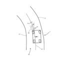
図2は、交通車線10上で進行する車両1を例示する。交通車線10は、例えば、白または黄に色付けされた、連続的な線の、または、断続的な線の形式で、交通車線上で具現される、2つの境界線11により、左で、および、右で限界を定められる。検出手段8は、境界線11を識別する能力がある。電子制御ユニットは、基準軌道12またはセットポイント軌道を算出することを可能にするソフトウェア手段を含む。基準軌道12は、図2において断続的な線により識別される。基準軌道12は、交通車線10上で可視でない、理論的な線である。基準軌道12は、例えば、車線の中心を体現し、例えば、2つの境界線11から等距離に据えられる線に対応し得る。変形例として、基準軌道12は、異なって規定され得る。その基準軌道12は、2つの境界線11の一方または他方に対して、より多く片寄らされ得る。その基準軌道12は、さらには、交通車線上に、または、交通車線10に近接する交通車線上に存在する、障害物の、または、他の車両の検出の相関的要素として算出され得る。
2 illustrates a
本文書において、長手方向軸Xは、車両1高さにおける、例えば、その車両1の重心の高さにおける、基準軌道に平行な交通車線の軸と規定される。横手方向軸Yは、車両1高さにおける、基準軌道に対して直角の交通車線の軸である。軸Zは、長手方向軸Xに対して、および、横手方向軸Yに対して直角であることを明示する。図2において例示される交通車線は、左に曲がる交通車線である。しかしながら、本発明は、交通車線が、直線的な線である、または、右に曲がっているときに、同等に実施され得る。
In this document, the longitudinal axis X is defined as the axis of the traffic lane parallel to the reference trajectory at
車両の状態、すなわち、交通車線10上のその車両の位置、および、その車両の軌道は、図2において部分的に表される、物理的数量または状態変数のセットにより特徴付けられ得る。とりわけ、車両の状態は、後に続く数量:
- 車両のヨー速度dΨ/dt、および/または、
- 車両の向首方向角度Ψ、および/または、
- 車両の横方向速度dy/dt、および/または、
- 基準軌道についての車両の横方向ずれy、および/または、
- 車両の被操舵輪の転回速度dδ/dt、および/または、
- 車両の被操舵輪の操舵角度δ、および/または、
- 基準軌道についての車両の横方向ずれの積分ly
により特徴付けられ得る。
The state of a vehicle, i.e., its position on the
the yaw rate dΨ/dt of the vehicle, and/or
the heading angle Ψ of the vehicle, and/or
the lateral speed dy/dt of the vehicle, and/or
the lateral deviation y of the vehicle relative to the reference trajectory, and/or
the turning speed dδ/dt of the steered wheels of the vehicle, and/or
the steering angle δ of the steered wheels of the vehicle, and/or
- integral of the lateral deviation of the vehicle with respect to the reference trajectory ly
It can be characterized by:
ヨー速度dΨ/dtは、軸Zの周りの車両の回転の速度である。ヨー速度は、例えば、ヨーセンサの手段により測定され得る。向首方向角度Ψは、交通車線10の長手方向軸X、すなわち、車両高さにおける基準軌道12に対して接線方向の軸と、車両の長手方向軸X1との間に形成される角度と規定され得る。横方向ずれyは、基準軌道12から、車両の所定の点(とりわけ、その車両の重心C)を隔てる距離と規定され得る。変形例として、横方向ずれyは、さらには、境界線11から車両の所定の点を隔てる距離の尺度となり得る。向首方向角度Ψおよび横方向ずれyは、例えば、車両の検出手段8を使用して算出され得る。横方向速度dy/dtは、横方向ずれyの、時間についての微分である。横方向ずれの積分lyは、時間について、および、制御方法のアクティブ化の時点に対応する初期時点から算出され得る。
The yaw rate dΨ/dt is the rate of rotation of the vehicle around the axis Z. The yaw rate can be measured, for example, by means of a yaw sensor. The heading angle Ψ can be defined as the angle formed between the longitudinal axis X of the
被操舵輪の操舵角度δは、被操舵前輪の転がる方向に平行な軸X2と、車両の長手方向軸X1との間に形成される角度と規定され得る。操舵角度δは、操舵輪角度センサ7により測定される操舵輪角度に比例する。車両が走っているとき、車両の2つの被操舵輪は、一般的には、被操舵輪の各々により追従される曲率の異なる半径を考慮に入れるために、わずかに異なる角度だけ転回されるということに留意されたい。これらの差は、次いで、無視できると考えられ得る。かくして、車両の状態は、いわゆる「自転車」モデルを使用することにより、すなわち、単一の被操舵輪を考えることにより単純化され得、その単一の被操舵輪に対して、操舵角度は、車両に、異なる操舵角度によって2つの被操舵輪が追従することになるのと同じ曲率を追従させる。「自転車」モデルを使用する被操舵輪の操舵角度は、例えば、左被操舵輪の操舵角度と、右被操舵輪の操舵角度との間の平均角度であり得る。操舵輪の転回速度dδ/dtは、操舵角度δの、時間についての微分である。
The steering angle δ of the steered wheel can be defined as the angle formed between the axis X2 parallel to the rolling direction of the steered front wheel and the longitudinal axis X1 of the vehicle. The steering angle δ is proportional to the steering wheel angle measured by the steering
注目距離Lが、所定の距離Lmaxと、車両の検出手段の視界到達範囲Lrangeとの間の最小値と規定され得る。検出手段の視界到達範囲は、検出手段が、良好なレベルの信頼度を伴って、または、十分な鮮明度を伴って、周囲を検出することができる、最大距離である。視界到達範囲は、とりわけ、検出手段内に埋め込まれるセンサの感度に、ただしさらには、明るさコンディション、および/または、気象もしくは大気コンディションに依存する。視界到達範囲は、さらには、追従される交通車線の類型に、および、検出手段8の前方における障害物の、または、別の車両の、可能性のある存在に依存する。特に、車両が転回を始めるとき、検出手段8の視界到達範囲は低減され得る。所定の距離Lmaxは、車両の較正により規定される値であり得る。その所定の距離Lmaxは、例えば、30メートルの値を伴って規定され得る。 The attention distance L may be defined as the minimum between the predetermined distance Lmax and the visibility range Lrange of the detection means of the vehicle. The visibility range of the detection means is the maximum distance at which the detection means can detect the surroundings with a good level of reliability or with sufficient clarity. The visibility range depends, inter alia, on the sensitivity of the sensors embedded in the detection means, but also on the lighting conditions and/or on the weather or atmospheric conditions. The visibility range also depends on the type of traffic lane to be followed and on the possible presence of an obstacle or of another vehicle in front of the detection means 8. In particular, when the vehicle starts to turn, the visibility range of the detection means 8 may be reduced. The predetermined distance Lmax may be a value defined by the calibration of the vehicle. It may be defined, for example, with a value of 30 meters.
注目距離Lは、とりわけ、図3において表される。比喩の言い方をすると、注目距離は、車両の屋根に取り付けられる「釣竿」とみなされ得る。注目距離における横方向ずれyLは、基準軌道12と、「釣竿」の端部とを隔てる横方向距離と規定され得る。換言すれば、横方向ずれyLは、車両レベルにおける基準軌道に対する接線に対して直角の方向における、基準軌道12と、車両1の前方における注目距離Lにある所定の点との間の横方向ずれに対応する。
The attention distance L is represented, inter alia, in FIG. 3. Metaphorically speaking, the attention distance can be considered as a "fishing rod" attached to the roof of the vehicle. The lateral deviation yL at the attention distance can be defined as the lateral distance separating the
横方向ずれyLは、多項式の形式で、とりわけ車両の重心Cにおいて、リアルタイムで横方向ずれを供給するカメラにより測定され、そのことは、(カメラの視域の限界の中の)任意の距離において、およびとりわけ、距離Lにおいて、横方向ずれを知ることを可能にする。 The lateral deviation yL is measured by a camera which provides the lateral deviation in real time in the form of a polynomial, in particular at the vehicle's centre of gravity C, which makes it possible to know the lateral deviation at any distance (within the limits of the camera's field of view) and in particular at the distance L.
図4を参照して、車両1の横方向位置を制御するための方法が、今から、本発明の1つの実施形態に従って説明されることになる。方法は、7つのステップ:E1からE7へと細分化され得る。この運転者支援方法は、所与の頻度に従って繰り返され得る。本明細書において下記で詳細に説かれることになるように、制御方法は、さらにはレギュレータと呼ばれる制御システムに頼る。制御システムは、第1の開ループ構成要素FFD(さらには「フィードフォワード」と呼ばれる)と、第2の閉ループ構成要素FBK(さらには「フィードバック」と呼ばれる)とを含む。本来、FFDループは反応的であり、対するに、FBKループはより遅鈍であり、そのことは、快適性を改善し、開ループモデルの誤差を補正することを可能にする。被操舵輪の操舵角度セットポイントは、第1の構成要素FFDと第2の構成要素FBKの総和により取得される。本発明は、転回において、FFD構成要素を緩和し、同時に、FBK構成要素の適応により補償することを、転回行為をより堅実な様態に変え、運転者の感じ方を改善するために行うことを可能にし、その運転者は、かくして、より優れた快適性から利益を得ることになる。
With reference to FIG. 4, a method for controlling the lateral position of a
第1のステップE1において、基準軌道12が算出される。基準軌道は、車両により追従されることになる軌道である。この最終目的のために、例えば、境界線11を検出手段8によって検出し、次いで、2つの境界線11から等距離に据えられる線として、基準軌道12を算出することが可能である。基準軌道は、制御システムに対する入力として使用される、基準状態ベクトルXrefにより表され得る。基準状態ベクトルXrefは、それゆえに、基準軌道12の関数として算出される。
In a first step E1, a
第2のステップE2において、車両の将来横方向加速度、すなわち、例えば較正により規定され得る時間T0の後に車両が耐えることになる横方向加速度が算出される。この最終目的のために、車両の前方における交通車線10の曲率が、まず第1に決定され得、この値は、車両がその曲率を基に進行していることになるときの横方向加速度を推定するために、車両の速度、およびおそらくは、車両の加速度と組み合わされ得る。例えば、車両の横方向加速度aymaxが、後に続く算式によって算出され得る。
aymax=ρ(Lmax).v2
その式において、
- p(Lmax)は、車両からの距離Lmaxにおける交通車線の曲率を明示する。
- vは、車両の速度を明示する。
In a second step E2, the future lateral acceleration of the vehicle is calculated, i.e. the lateral acceleration that the vehicle will endure after a time T0, which may be defined, for example, by calibration. For this purpose, the curvature of the
ay max = ρ(Lmax). v 2
In that formula,
- p(Lmax) specifies the curvature of the traffic lane at a distance Lmax from the vehicle.
- v denotes the speed of the vehicle.
交通車線の曲率は、さらには、車両からの固定された距離において算出され得る。その曲率は、検出手段が十分な視界到達範囲を有する場合、それらの検出手段を使用して決定され、さもなければ、車載ナビゲーションシステム9を用いて取得され得る。後者のことを想定すると、交通車線の曲率は、ナビゲーションシステムから電子制御ユニットに送出され得る。ナビゲーションシステムからのデータの使用は、検出手段が不十分な視界到達範囲を有するときでさえ、交通車線の曲率を算出することを可能にする。
The curvature of the traffic lane may furthermore be calculated at a fixed distance from the vehicle. The curvature may be determined using the detection means if they have sufficient visibility coverage, otherwise it may be obtained using the on-
第3のステップE3において、横方向加速度は、しきい値S1と比較される。このしきい値S1は、例えば、0.2gまたは0.25gに等しくあり得るが、変形例として、そのしきい値S1は、車両に関する試験の後に選定される、異なる値を伴って規定され得る。この比較は、転回があまり急でない、および、横方向加速度が低い、通常の運転状況を、転回がより急である、および、検出手段の視界到達範囲が低減される、運転状況と区別することを可能にする。 In a third step E3, the lateral acceleration is compared with a threshold value S1. This threshold value S1 may be equal to 0.2 g or 0.25 g, for example, but as a variant it may be defined with a different value, chosen after tests on the vehicle. This comparison makes it possible to distinguish normal driving situations, in which the turn is not very sharp and the lateral acceleration is low, from driving situations in which the turn is sharper and the visual reach of the detection means is reduced.
第4のステップE4において、開ループ構成要素FFDの寄与に重み付けするために、開ループ構成要素を算出するために有用であることになる、利得Gが算出される。横方向加速度が、しきい値S1以上である、または、厳密にしきい値S1未満である場合による、2つの事例が区別され得る。 In a fourth step E4, a gain G is calculated, which will be useful for calculating the open-loop component FFD in order to weight the contribution of the open-loop component. Two cases can be distinguished depending on whether the lateral acceleration is greater than or equal to the threshold value S1 or whether it is strictly less than the threshold value S1.
横方向加速度が厳密にしきい値S1未満である場合の事例において、利得Gは、注目距離Lの減少関数と規定される。換言すれば、注目距離が大きいほど、利得Gは低く、セットポイント角度の算出における開ループ構成要素FFDの寄与は低い。 In the case where the lateral acceleration is strictly less than the threshold S1, the gain G is defined as a decreasing function of the attention distance L. In other words, the larger the attention distance, the lower the gain G and the lower the contribution of the open loop component FFD in the calculation of the setpoint angle.
利得Gは、0以上1以下であり得る。開ループ構成要素の寄与は、それゆえに、多くとも、利得Gの算入が欠如した様態でその寄与が有することになる値に等しく、利得Gが厳密に1未満であるとき、操舵角度セットポイントの算出への開ループ構成要素の寄与は、そのとき低減される。 The gain G can be greater than or equal to 0 and less than or equal to 1. The contribution of the open loop component is therefore at most equal to the value that it would have in the absence of the inclusion of gain G; when gain G is strictly less than 1, the contribution of the open loop component to the calculation of the steering angle setpoint is then reduced.
利得Gは、注目距離が0であるときに1に等しくあり得る。かくして、検出手段の視界到達範囲が0である場合、開ループ構成要素の寄与は低減されない。 The gain G may be equal to 1 when the attention distance is 0. Thus, when the visual reach of the detection means is 0, the contribution of the open loop components is not reduced.
より詳細には、および、依然として、横方向加速度が厳密にしきい値S1未満である場合の事例において、第4のステップE4は、車両1内に設置される検出手段の注目距離Lが算出される、第1のサブステップE41を含むことができる。先に確認されたように、注目距離Lは、後に続く算式によって算出され得る。
L=min(Lmax,Lrange)
その式において、
- Lmaxは、所定の距離を明示する。
- Lrangeは、車両の検出手段の視界到達範囲を明示する。
More specifically, and still in the case where the lateral acceleration is strictly less than the threshold value S1, the fourth step E4 can comprise a first sub-step E41 in which the attention distance L of the detection means installed in the
L=min(Lmax, Lrange)
In that formula,
- Lmax designates a predetermined distance.
- Lrange specifies the visibility range of the vehicle's detection means.
次に、第2のサブステップE42において、利得Gは、注目距離に依存的な関数の手段により算出され得る。利得Gは、とりわけ、後に続く算式によって算出され得る。

横方向加速度がしきい値S1以上である場合の事例において、利得Gは、注目距離に依存しない所定の値γにセットされ得る。 In cases where the lateral acceleration is greater than or equal to the threshold value S1, the gain G can be set to a predetermined value γ that is independent of the focus distance.
次に、第5のステップE5において、操舵角度セットポイントの開ループ構成要素FFDが算出される。この開ループ構成要素は、第4のステップE4において算出される利得Gにより重み付けされる、道路の曲率に追従するために必要な被操舵輪の操舵角度δeqに実質的に等しくあり得る。かくして、開ループ構成要素は、後に続く算式によって算出され得る。
FFD=G.δeq
Next, in a fifth step E5, an open loop component FFD of the steering angle setpoint is calculated. This open loop component may be substantially equal to the steering angle δ of the steered wheels required to follow the curvature of the road weighted by the gain G calculated in the fourth step E4. Thus, the open loop component may be calculated according to the following formula:
FFD = G. δeq
道路の曲率に追従するために必要な被操舵輪の操舵角度δeqは、後に続く算式により算出され得る。

- ρは、車両高さにおける交通車線の曲率を明示する
- vは、車両の速度を明示する
- a11、a12、a16、a31、a32、a36は、以後規定されることになる行列Aの構成要素であり、これらの構成要素は、車両1の、および、その車両1の速度の固有の特性の関数である。
The steering angle δeq of the steered wheels required to follow the curvature of the road can be calculated by the following formula.
- ρ specifies the curvature of the traffic lane at vehicle height; - v specifies the speed of the vehicle; - a11, a12, a16, a31, a32, a36 are elements of matrix A to be defined hereafter, which are functions of the specific characteristics of
第6のステップE6において、操舵角度セットポイントの閉ループ構成要素FBKが算出される。閉ループ構成要素は、車両の状態、および/または、外側のコンディションに関わらず、基準軌道に最も良好に追従する、開ループ構成要素を補正することを可能にする。閉ループ構成要素は、閉ループレギュレータの手段により算出される。このレギュレータは、車両の状態表現に基づく。閉ループ構成要素は、すべての基準状態ベクトルXrefを補正すること、ならびにとりわけ、向首方向角度Ψ、向首方向角度の微分dΨ/dt、および、輪の操舵角度δを補正することを、これらのパラメータを基準状態ベクトルXrefのパラメータと一致させるように行うことを目標とする。 In a sixth step E6, the closed-loop components FBK of the steering angle setpoint are calculated. The closed-loop components make it possible to correct the open-loop components, which best follow the reference trajectory, regardless of the state of the vehicle and/or the external conditions. The closed-loop components are calculated by means of a closed-loop regulator, which is based on a representation of the state of the vehicle. The closed-loop components aim to correct all the reference state vectors Xref, and in particular the heading angle Ψ, the heading angle derivative dΨ/dt and the wheel steering angle δ, in such a way that these parameters correspond to those of the reference state vector Xref.
図5は、本発明の実施形態による制御システムを表す。ハイブリッドベクトルXhybが、表現を単純化するために、観測器の出力として、その図5において表されるが、念頭に置かれたいのは、この出力は直接的ではなく、なぜならば、ハイブリッドベクトルXhybであって、そのハイブリッドベクトルの2つの観測される状態に対して再構築されることが、これらの2つの状態に対する観測器の直接的な出力を再び取り込むことにより、および、5つの他の状態の測定される値を再び取り込むことにより行われる、ハイブリッドベクトルXhybが選定されているからであるということである。それでも、変形例として、ベクトルXhybは、ハイブリッドではなく、図5において表されるような、観測される状態のみを内包することがある。 Figure 5 shows a control system according to an embodiment of the invention. The hybrid vector Xhyb is represented in that figure as the output of the observer for simplicity of presentation, but keep in mind that this output is not direct because a hybrid vector Xhyb has been chosen that is reconstructed for the two observed states of the hybrid vector by reincorporating the direct outputs of the observer for these two states and by reincorporating the measured values of the five other states. Nevertheless, as a variant, the vector Xhyb may contain only the observed states as represented in figure 5, rather than the hybrid.
第6のステップE6の第1のサブステップE61において、交通車線11上の車両の位置および軌道を特徴付ける、観測される状態ベクトルが算出され、5つの測定値(dΨ/dt、Ψ、yL、δ、および、-ly)と、2つの観測される状態(dy/dtおよびdδ/dt)とを内包するハイブリッド状態ベクトルXhybが、測定により知られないこれらの状態dy/dtおよびdδ/dtを再構築するために再構築される。セットポイントを組成する車両の基準状態ベクトルXrefは、所与の瞬間におけるハイブリッド状態ベクトルに非依存的である。ハイブリッド状態ベクトルは、後に続くように規定され得る。

ハイブリッド状態ベクトルは、それゆえに、7つの構成要素を含む。一般的には、状態ベクトルは、所与の瞬間において車両により経験される、位置、速度、および加速度を特徴付けることができる。ハイブリッド状態ベクトルは、それゆえに、時間的に可変なベクトルである。ハイブリッド状態ベクトルの7つの構成要素のうち、構成要素dΨ/dt、Ψ、dy/dt、dδ/dt、δ、および、-lyは、車両1の、現在の瞬間、すなわち、その間に制御方法が実行される瞬間における、または、その車両1の現実の位置における、位置および軌道を特徴付ける。先に確認されたように、特性yLは、車両レベルにおける軌道に対する接線に対して直角の、車両の前方における注目距離Lにある所定の点の、基準軌道12についての横方向ずれに対応する。変形例として、状態ベクトルの構成要素は、異なる順序で提示されることがある。後に続く説明は、しからば、そのことに従って適合させられることになる。
The hybrid state vector therefore comprises seven components. In general, the state vector can characterize the position, velocity and acceleration experienced by the vehicle at a given instant. The hybrid state vector is therefore a time-variable vector. Of the seven components of the hybrid state vector, the components dΨ/dt, Ψ, dy/dt, dδ/dt, δ and -ly characterize the position and trajectory of the
ハイブリッド状態ベクトルXhybは、観測されるベクトルから、および、測定値から再構築され、そのため、そのハイブリッド状態ベクトルは、それゆえに、車両内に埋め込まれるセンサから、(図5において21により識別される)車両の運動力学モデルから、および、(図5において22により識別される)観測器から算出される。運動力学モデル21は、後に続く式により説明され得る。
dXhyb/dt=A.Xhyb+B1.δc+B2.ρ
The hybrid state vector Xhyb is reconstructed from the observed vector and from the measurements, which are therefore calculated from sensors embedded in the vehicle, from a kinematic model of the vehicle (identified by 21 in FIG. 5 ), and from the observers (identified by 22 in FIG. 5 ). The
dXhyb/dt=A. Xhyb+B1. δc+B2. ρ
所定の式であり、その式において、
- dXhyb/dtは、ハイブリッド状態ベクトルXhybの、時間についての微分である、
- δcは、制御方法の先立つ反復において算出された被操舵輪の操舵角度セットポイントである、
- ρは、交通車線の曲率である、
- Aは、下記で規定されることになる7x7行列である、
- B1およびB2は、下記で規定される7つの構成要素を伴うベクトルである。
A given formula, in which:
dXhyb/dt is the derivative with respect to time of the hybrid state vector Xhyb;
- δc is the steered wheel steering angle setpoint calculated in a previous iteration of the control method;
- ρ is the curvature of the traffic lane,
- A is a 7x7 matrix as will be defined below:
B1 and B2 are vectors with seven components defined below.
行列Aは、後に続く算式により規定され得る。
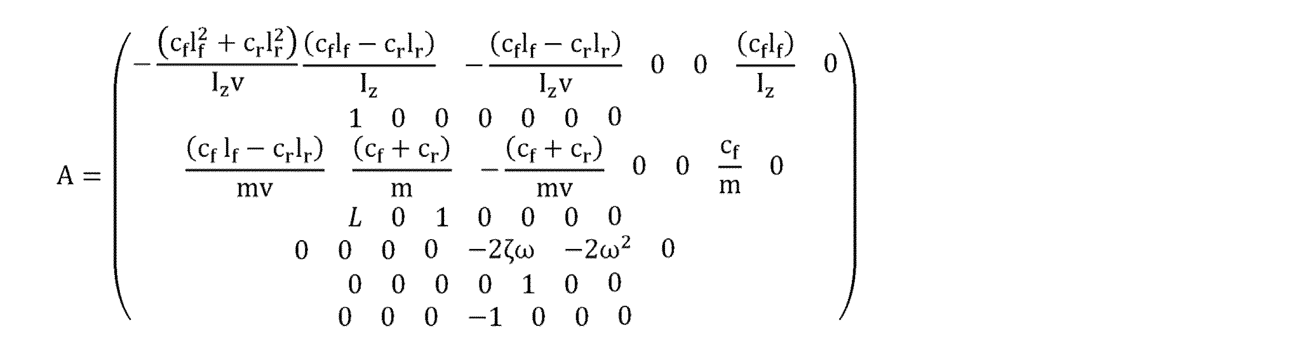
- cfは、車両のフロントサスペンションのドリフト剛性を明示する、
- crは、車両のリアサスペンションのドリフト剛性を明示する、
- lfは、車両の重心Cとフロントサスペンションとの間の距離を明示する、
- lrは、車両の重心Cとリアサスペンションとの間の距離を明示する、
- lzは、車両の慣性を明示する、
- mは、車両の重量を明示する、
- vは、車両の速度を明示する、
- ζは、操舵システムの減衰因子を明示する、
- ωは、操舵システムのフィルタの自然振動数を明示する、
- Lは、注目距離を明示する。
The matrix A may be defined by the following formula:
- cf specifies the drift stiffness of the vehicle's front suspension,
- cr specifies the drift stiffness of the vehicle's rear suspension,
- lf denotes the distance between the center of gravity C of the vehicle and the front suspension,
- lr defines the distance between the center of gravity C of the vehicle and the rear suspension,
- lz defines the inertia of the vehicle,
- m specifies the weight of the vehicle,
- v denotes the speed of the vehicle,
- ζ specifies the damping factor of the steering system,
- ω defines the natural frequency of the steering system filter,
- L designates the attention distance.
パラメータcf、cr、lf、lr、lz、m、ζ、およびωは、それゆえに、車両を特徴付ける定数である。それらのパラメータは、車両のチューニングにおけるすべての事例に対して1回規定され、電子制御ユニットのメモリ内に記憶され得る。 The parameters cf , cr , lf, lr , lz , m , ζ, and ω are therefore constants that characterize the vehicle and can be defined once for all cases in tuning the vehicle and stored in the memory of the electronic control unit.
「aij」を使用して、行列Aの行iの、および、列jの構成要素を規定することにより、開ループ構成要素FFDを算出することにおいて必然的に含まれる、操舵角度δeqを算出することに対して有用な、パラメータa11、a12、a16、a31、a32、a36が規定される。特に、後に続くものが適用される。

行列Aは、状態ベクトルXhybを乗算される。行列A内の注目距離Lの組み込みは、開ループ構成要素FFDに利得Gを乗算することに起因する、その開ループ構成要素FFDの低減を補償することを可能にする。かくして、有利には、注目距離が大きいほど、開ループ構成要素の重みは低く、閉ループ構成要素FBKの重みは大きい。変形例として、注目距離Lは、閉ループ構成要素を算出することにおいて、任意の他の手立てで組み込まれ得る。 The matrix A is multiplied by the state vector Xhyb. The incorporation of the attention distance L in the matrix A makes it possible to compensate for the reduction of the open-loop component FFD due to its multiplication by the gain G. Thus, advantageously, the larger the attention distance, the lower the weight of the open-loop component and the higher the weight of the closed-loop component FBK. As a variant, the attention distance L can be incorporated in any other way in calculating the closed-loop components.
ベクトルB1は、後に続く算式により規定され得る。

ベクトルB2は、後に続く算式により規定され得る。

- vは、車両の速度を明示する。
- Lは、注目距離を明示する。
Vector B2 may be defined by the following formula:
- v denotes the speed of the vehicle.
- L designates the attention distance.
その上、測定ベクトルYが、後に続く算式により規定され得る。
Y=C.Xhyb
その式において、Cは、車両1内に埋め込まれるセンサから直接的に入手可能である、ハイブリッドベクトルXhybを成り立たせる状態変数を分離することを可能にする対角行列を明示する。行列Cは、それゆえに、車両上で入手可能である測定値に依存する行列である。ベクトルYは、しからば、後に続く算式により規定され得る。

Y=C.Xhyb
In that formula, C denotes a diagonal matrix that makes it possible to separate the state variables making up the hybrid vector Xhyb that are directly available from sensors embedded in the
上記で提示された運動力学モデル21に、観測器22に、および、ベクトルYに基づいて、状態ベクトルXhybは算出され得る。観測器22は、ハイブリッド状態ベクトルの測定されない構成要素を推定することを可能にする。観測器22は、入力、一方においては、方法の先立つ反復において算出された閉ループ構成要素FBK、および、他方においては、ベクトルYとして使用され得る。車両は直線的な線上にあるという原則から開始するとき、ゼロに等しい基準状態ベクトルXrefが使用される。曲がり目に追従するために必要な被操舵輪の操舵角度は、開ループ構成要素FFDにより供給される。その上、測定値は、さらには、状態ベクトルXhybの曲がり目部分を「抽出する」ために補正されなければならない。このことをするために、下記の算式により規定されるベクトルY1が、ベクトルYから減算され得る。

第6のステップE6の第2のサブステップE62において、閉ループ構成要素FBKが、車両の基準状態ベクトルXrefとハイブリッド状態ベクトルXhybとの間の比較を基礎として算出される。基準状態ベクトルXrefとハイブリッド状態ベクトルXhybとの間の差が、まず第1に算出される。車両の理論的な状態と、その車両の現実の状態との間の誤差を表すベクトルXerrが、かくして取得される。ベクトルXerrは、それゆえに、後に続く算式により規定され得る。
Xerr=Xref-Xhyb
In a second sub-step E62 of the sixth step E6, the closed-loop components FBK are calculated on the basis of a comparison between the reference state vector Xref of the vehicle and the hybrid state vector Xhyb. The difference between the reference state vector Xref and the hybrid state vector Xhyb is first calculated. A vector Xerr is thus obtained, which represents the error between the theoretical state of the vehicle and the actual state of the vehicle. The vector Xerr can therefore be defined by the following formula:
Xerr=Xref-Xhyb
ベクトルXerrは、次いで、車両の速度vに依存的な、制御ベクトルKsを乗算される。閉ループ構成要素は、かくして、後に続く算出により取得される。
FBK=Ks.Xerr
The vector Xerr is then multiplied by a control vector Ks, which is dependent on the vehicle speed v. The closed loop components are thus obtained by the following calculations.
FBK=Ks. Xerr
ベクトルKsは、車両の速度の関数として規定されるということに留意されたい。電子制御ユニットのメモリは、それゆえに、所定の速度値に対して規定されるベクトルKsの異なる値を内包し得る。車両が、実際に、2つの所定の速度値の間の中間の速度において進行するとき、ベクトルKsは、車両の現実の速度より大きい速度、および、その現実の速度未満の速度に対して記憶されるベクトルKsの重み付けにより内挿され得る。 It should be noted that the vector Ks is defined as a function of the speed of the vehicle. The memory of the electronic control unit may therefore contain different values of the vector Ks defined for predefined speed values. When the vehicle actually travels at a speed intermediate between two predefined speed values, the vector Ks may be interpolated by weighting the vector Ks stored for speeds greater than and less than the actual speed of the vehicle.
第7のステップE7において、被操舵輪の操舵角度セットポイントδcが、開ループ構成要素FFDおよび閉ループ構成要素FBKを加算することにより算出される。操舵角度セットポイントδcは、それゆえに、後に続く算式を使用して算出され得る。
δc=FBK+FFD
In a seventh step E7, the steering angle set point δc of the steered wheels is calculated by adding the open loop component FFD and the closed loop component FBK. The steering angle set point δc can therefore be calculated using the following formula:
δc=FBK+FFD
操舵角度セットポイントδcは、次いで、操舵角度セットポイントδcに従って被操舵輪の向きを定める操舵デバイス4に送出される。このセットポイントδcは、さらには、制御方法の次の反復におけるハイブリッド状態ベクトルXhybの算出のために使用される。
The steering angle setpoint δc is then sent to the
先程説明された制御方法は、被操舵輪の操舵角度を算出するための方法に、同等に置き換えられ得、なぜならば、その操舵角度は、車両の横方向位置を調整することを可能にする、車両の被操舵輪の向きであるからであるということに留意されたい。なおまた、方法は、さらには、操舵輪角度を算出するための方法に置き換えられ得、なぜならば、操舵輪角度、および、被操舵輪の操舵角度は、比例関係の結び付きにより互いに結び付けられるからである。制御方法は、さらには、車両の横方向位置と、知られている関数により相関させられる、任意の数量に適用され得る。 It should be noted that the control method just described can be equivalently replaced by a method for calculating the steering angle of the steered wheels, since the steering angle is the orientation of the steered wheels of the vehicle that allows the lateral position of the vehicle to be adjusted. Furthermore, the method can also be replaced by a method for calculating the steering wheel angle, since the steering wheel angle and the steering angle of the steered wheels are linked to each other by a proportional relationship. The control method can also be applied to any quantity that is correlated to the lateral position of the vehicle by a known function.
本発明のおかげで、車両の動的挙動を混乱させることがある要因に、より非依存的である、被操舵輪の操舵角度セットポイントの角度算出が達成される。本発明による方法は、これらの要因の事前の識別を要さない。 Thanks to the present invention, a calculation of the steering angle setpoint of the steered wheels is achieved that is more independent of factors that can perturb the dynamic behavior of the vehicle. The method according to the present invention does not require prior identification of these factors.
本発明は、さらには、車両の横方向位置を制御するための方法を較正するための方法に関する。制御方法の、較正、または換言すれば、パラメータ化のために、走行路上での試験が実施され得る。制御方法の較正は、とりわけ、先に規定されたパラメータβおよびγに対する値を決定することを目標とする。 The invention further relates to a method for calibrating a method for controlling the lateral position of a vehicle. For the calibration, or in other words parameterization, of the control method, on-road tests can be carried out. The calibration of the control method aims, inter alia, at determining values for the parameters β and γ defined above.
較正方法の第1のステップC1において、車両が厳密にしきい値S1未満の横方向加速度を経験することになる、第1のコース上で、試験が実施される。第1のステップC1は、車両が第1のコースを走るときに、基準軌道12についての車両の横方向ずれを測定する第1のサブステップC11であって、注目距離はゼロに等しいと規定される、車両の横方向ずれを測定する第1のサブステップC11を含む。基準横方向ずれyrefが、かくして取得される。
In a first step C1 of the calibration method, a test is carried out on a first course, during which the vehicle experiences a lateral acceleration strictly below the threshold value S1. The first step C1 includes a first sub-step C11 of measuring the lateral deviation of the vehicle with respect to the
第2のサブステップC12において、第1のコースが再度走られ、注目距離が、利得Gの低減とともに漸進的に増大される。この第2のステップC12は、基準軌道についての車両の横方向ずれyが、基準横方向ずれyrefに実質的に等しい限りにおいて繰り返される。「実質的に等しい」は、横方向ずれyと基準横方向ずれyrefとの間の差がしきい値未満であるということを意味すると理解されるべきである。注目距離の特性が、かくして、利得Gの関数として構築され得る。この特性に基づいて、この特性に最も良好に近付くことを可能にするパラメータβが規定され得る。 In a second sub-step C12, the first course is run again and the attention distance is progressively increased with a reduction in the gain G. This second step C12 is repeated as long as the lateral deviation y of the vehicle with respect to the reference trajectory is substantially equal to the reference lateral deviation yref. "Substantially equal" should be understood to mean that the difference between the lateral deviation y and the reference lateral deviation yref is less than a threshold value. A characteristic of the attention distance can thus be constructed as a function of the gain G. On the basis of this characteristic, a parameter β can be defined that allows to best approach this characteristic.
較正方法の第2のステップC2において、車両がしきい値S1以上の横方向加速度を経験することになる、第2のコース上で、試験が実施される。第2のステップC2は、車両の注目距離Lを規定する第1のサブステップC21を含む。注目距離Lは、そのとき、所定の距離Lmaxに等しいと規定される。 In a second step C2 of the calibration method, a test is carried out on a second course where the vehicle experiences a lateral acceleration equal to or greater than the threshold value S1. The second step C2 includes a first sub-step C21 of defining a focus distance L of the vehicle. The focus distance L is then defined as being equal to a predetermined distance Lmax.
第2のサブステップC22において、第2のコースが、利得Gを漸進的に増大しながら、続けざまに走られる。第2のサブステップC22は、基準軌道についての車両の横方向ずれが、しきい値、例えば、30センチメートルのしきい値以下であるまで繰り返される。このしきい値未満の、基準軌道についての横方向ずれを達成することを可能にする利得Gの値が、利得値γと規定され得る。 In a second sub-step C22, the second course is run in succession with a progressive increase in the gain G. The second sub-step C22 is repeated until the lateral deviation of the vehicle with respect to the reference track is below a threshold value, for example a threshold value of 30 centimeters. The value of the gain G that makes it possible to achieve a lateral deviation with respect to the reference track below this threshold value can be defined as the gain value γ.
最終的には、周回路上での試験を通して、理想的な妥協点が、交通車線上の車両の横方向位置を制御するために、見出されることがやりこなされる。一方においては、車両は、基準軌道に、その基準軌道から過度にずれることなく追従する。とりわけ、車両は、過度に曲がり目をショートカットしない。他方においては、車両は、乗り手に対する、ジャーク、または、不愉快な不意の移動なしに制御される。 Finally, through tests on circuit tracks, it is worked out that an ideal compromise is found for controlling the lateral position of the vehicle on the traffic lane. On the one hand, the vehicle follows a reference trajectory without deviating excessively from it. In particular, the vehicle does not shortcut turns excessively. On the other hand, the vehicle is controlled without jerks or unpleasant unexpected movements for the rider.
本発明は、さらには、四輪駆動による車両への適用に適し、適した自転車モデルが、単純に使用されることを必要とすることになる。 The present invention is further suitable for application in vehicles with four-wheel drive, requiring that a suitable bicycle model be simply used.
Claims (12)
- 前記モータ車両(1)の将来横方向加速度を算出するステップ(E2)と、
- 前記横方向加速度を、しきい値(S1)と比較するステップ(E3)と、
- 前記モータ車両(1)内に設置される検出手段(8)の注目距離(L)であって、前記モータ車両(1)の重心を通って前記モータ車両(1)の長手方向に沿った注目距離(L)を算出するステップ(E41)と、
- 前記モータ車両(1)の被操舵輪(2f)の操舵角度セットポイント(δc)の第1の構成要素(FFD)を算出するステップ(E5)であって、前記第1の構成要素(FFD)は、前記制御システムの開ループ構成要素であり、前記横方向加速度が厳密に前記しきい値(S1)未満である場合、前記第1の構成要素(FFD)は、利得(G)により重み付けされ、前記利得(G)は、前記注目距離(L)の減少関数である、第1の構成要素(FFD)を算出するステップ(E5)と、
- 前記操舵角度セットポイント(δc)の第2の構成要素(FBK)を算出するステップ(E6)であって、前記第2の構成要素(FBK)は、前記制御システムの閉ループ構成要素である、第2の構成要素(FBK)を算出するステップ(E6)と
を含み、
前記第2の構成要素(FBK)を算出する前記ステップ(E6)は、前記モータ車両(1)の状態ベクトル(Xhyb)を算出するサブステップ(E61)であって、前記状態ベクトル(Xhyb)は、前記注目距離(L)における基準軌道(12)についての前記モータ車両(1)の横方向ずれ(yL)に等しい構成要素を含む、前記モータ車両(1)の状態ベクトル(Xhyb)を算出するサブステップ(E61)を含み、
前記第2の構成要素(FBK)を算出する前記ステップ(E6)は、前記注目距離(L)における前記モータ車両(1)の前記横方向ずれ(yL)に前記注目距離(L)を乗算するサブステップを含むことを特徴とする、制御方法。 A control method for controlling a lateral position of a motor vehicle (1) by a control system, comprising:
a step (E2) of calculating a future lateral acceleration of the motor vehicle (1);
a step (E3) of comparing said lateral acceleration with a threshold value (S1);
a step (E41) of calculating a focus distance (L) of the detection means (8) installed in said motor vehicle (1), said focus distance (L) passing through the centre of gravity of said motor vehicle (1) along the longitudinal direction of said motor vehicle (1);
a step (E5) of calculating a first component (FFD) of the steering angle setpoint (δc) of the steered wheels (2f) of the motor vehicle (1), said first component (FFD) being an open-loop component of the control system, said first component (FFD) being weighted by a gain (G) which is a decreasing function of said distance of attention (L) when said lateral acceleration is strictly below said threshold value (S1);
a step (E6) of calculating a second component (FBK) of said steering angle setpoint (δc), said second component (FBK) being a closed-loop component of said control system,
The step (E6) of calculating the second component (FBK) includes a sub-step (E61) of calculating a state vector (Xhyb) of the motor vehicle (1), the state vector (Xhyb) including a component equal to a lateral deviation (yL) of the motor vehicle (1) with respect to a reference trajectory (12) at the attention distance (L) ,
The control method, characterized in that the step (E6) of calculating the second component (FBK) includes a substep of multiplying the lateral deviation (yL) of the motor vehicle (1) at the attention distance (L) by the attention distance (L) .
- 前記モータ車両(1)がしきい値S1未満の横方向加速度を経験することになる第1のコースを走るときに、前記注目距離(L)はゼロに等しいと規定されて、前記基準軌道(12)についての前記モータ車両(1)の基準横方向ずれ(yref)を測定する第1のステップ(C11)と、
- 前記モータ車両が前記第1のコースを走るときに、前記基準軌道(12)についての前記モータ車両の横方向ずれ(y)が、前記基準横方向ずれ(yref)に等しい限りにおいて、前記注目距離(L)を漸進的に増大し、前記利得(G)を低減する第2のステップ(C12)と
を含むことを特徴とする、
および/または、
- 前記モータ車両(1)がしきい値S1以上の横方向加速度を経験することになる第2のコースを走るときに、前記注目距離(L)が所定の距離(Lmax)に等しいことを規定する第1のステップ(C21)と、
- 前記モータ車両が前記第2のコースを走るときに、前記基準軌道(12)についての前記モータ車両の横方向ずれ(y)がしきい値以下になるまで、前記利得(G)を漸進的に増大する第2のステップ(C22)と
を含むことを特徴とする、方法。 A method for calibrating the steering system (3) of a motor vehicle (1) according to claim 11 , comprising the steps of:
a first step (C11) of measuring a reference lateral deviation (yref) of said motor vehicle (1) with respect to said reference trajectory (12), said reference distance (L) being defined as equal to zero, when said motor vehicle (1) travels a first course during which it experiences a lateral acceleration less than a threshold value S1;
a second step (C12) of progressively increasing said attention distance (L) and reducing said gain (G) as long as the lateral deviation (y) of said motor vehicle with respect to said reference trajectory (12) is equal to said reference lateral deviation (yref) when said motor vehicle travels said first course,
and/or
a first step (C21) of defining that said distance of interest (L) is equal to a predetermined distance (Lmax) when said motor vehicle (1) travels a second course during which it experiences a lateral acceleration equal to or greater than a threshold value S1;
a second step (C22) of progressively increasing said gain (G) as said motor vehicle traverses said second course, until the lateral deviation (y) of said motor vehicle with respect to said reference trajectory (12) is below a threshold value.
Applications Claiming Priority (3)
| Application Number | Priority Date | Filing Date | Title |
|---|---|---|---|
| FR1910267A FR3100780B1 (en) | 2019-09-17 | 2019-09-17 | Method for regulating the lateral position of a motor vehicle. |
| FR1910267 | 2019-09-17 | ||
| PCT/EP2020/074610 WO2021052771A1 (en) | 2019-09-17 | 2020-09-03 | Method for controlling the lateral position of a motor vehicle |
Publications (2)
| Publication Number | Publication Date |
|---|---|
| JP2022552087A JP2022552087A (en) | 2022-12-15 |
| JP7686630B2 true JP7686630B2 (en) | 2025-06-02 |
Family
ID=69190893
Family Applications (1)
| Application Number | Title | Priority Date | Filing Date |
|---|---|---|---|
| JP2022517326A Active JP7686630B2 (en) | 2019-09-17 | 2020-09-03 | Method for controlling the lateral position of a motor vehicle - Patents.com |
Country Status (6)
| Country | Link |
|---|---|
| US (1) | US11654966B2 (en) |
| EP (1) | EP4031427B1 (en) |
| JP (1) | JP7686630B2 (en) |
| CN (1) | CN114423655B (en) |
| FR (1) | FR3100780B1 (en) |
| WO (1) | WO2021052771A1 (en) |
Families Citing this family (7)
| Publication number | Priority date | Publication date | Assignee | Title |
|---|---|---|---|---|
| FR3100780B1 (en) * | 2019-09-17 | 2021-09-24 | Renault Sas | Method for regulating the lateral position of a motor vehicle. |
| FR3110130B1 (en) * | 2020-05-12 | 2022-07-01 | Renault Sas | Trajectory control module, trajectory control device and associated method |
| US12130626B2 (en) * | 2020-12-30 | 2024-10-29 | Jingsheng Yu | Lateral control in path-tracking of autonomous vehicle |
| CN114604251A (en) * | 2022-03-31 | 2022-06-10 | 芜湖雄狮汽车科技有限公司 | Vehicle lateral control method, device, vehicle and storage medium |
| FR3138098A1 (en) * | 2022-07-25 | 2024-01-26 | Psa Automobiles Sa | Method and device for determining a yaw rotation speed of a vehicle |
| FR3141909B1 (en) * | 2022-11-14 | 2025-09-19 | Renault Sas | Method of steering a motor vehicle in the center of its lane |
| CN119937385B (en) * | 2025-01-06 | 2025-09-26 | 湖南大学 | Four-wheel steering intelligent vehicle transverse dynamics parameter identification method based on time sequence prediction network |
Citations (4)
| Publication number | Priority date | Publication date | Assignee | Title |
|---|---|---|---|---|
| JP2010149637A (en) | 2008-12-24 | 2010-07-08 | Equos Research Co Ltd | Vehicle |
| JP2014019262A (en) | 2012-07-17 | 2014-02-03 | Fuji Heavy Ind Ltd | Vehicular drive support device |
| JP2018161996A (en) | 2017-03-27 | 2018-10-18 | 株式会社Subaru | Travel control device of vehicle |
| JP2018203018A (en) | 2017-06-02 | 2018-12-27 | 本田技研工業株式会社 | Travel control device, travel control method, and program |
Family Cites Families (15)
| Publication number | Priority date | Publication date | Assignee | Title |
|---|---|---|---|---|
| US7130729B2 (en) * | 2004-07-26 | 2006-10-31 | General Motors Corporation | Adaptive compensation of rear-wheel steering control using vehicle dynamics parameter estimation |
| WO2007063397A1 (en) * | 2005-12-01 | 2007-06-07 | Toyota Jidosha Kabushiki Kaisha | Driving assistance system and driving assistance method |
| DE602006017101D1 (en) * | 2005-12-27 | 2010-11-04 | Honda Motor Co Ltd | VEHICLE CONTROL DEVICE |
| US7599774B2 (en) * | 2006-03-10 | 2009-10-06 | Gm Global Technology Operations, Inc. | Method and system for adaptively compensating closed-loop front-wheel steering control |
| FR2915447B1 (en) * | 2007-04-30 | 2009-11-20 | Peugeot Citroen Automobiles Sa | METHOD OF MODELING A MOTOR VEHICLE |
| WO2009022947A1 (en) * | 2007-08-15 | 2009-02-19 | Volvo Technology Corporation | Operating method and system for supporting lane keeping of a vehicle |
| FR2943974A3 (en) * | 2009-04-07 | 2010-10-08 | Renault Sas | METHOD FOR OPERATING A SYSTEM FOR CORRECTING THE TRACK OF A MOTOR VEHICLE |
| DE102012224125B4 (en) * | 2012-01-02 | 2024-03-07 | Ford Global Technologies, Llc | Method for lane keeping support for a driver of a motor vehicle and lane keeping assistance system |
| JP6354656B2 (en) * | 2015-05-07 | 2018-07-11 | 株式会社デンソー | Vehicle position control device |
| FR3037024B1 (en) * | 2015-06-08 | 2018-12-07 | Jtekt Europe | USE OF STEERING ASSISTANCE TO COMPENSATE NEGATIVE EFFECTS INDUCED BY LIMITED SLIP DIFFERENTIAL |
| JP6078124B1 (en) * | 2015-08-27 | 2017-02-08 | 富士重工業株式会社 | Vehicle control apparatus and vehicle control method |
| FR3041590B1 (en) * | 2015-09-30 | 2018-08-17 | Renault S.A.S | SYSTEM FOR CONTROLLING THE DIRECTION OF A MOTOR VEHICLE IN THE EVENT OF AN IMMINENT COLLISION WITH AN OBSTACLE |
| FR3051756B1 (en) * | 2016-05-24 | 2020-03-20 | Renault S.A.S | VEHICLE TRAJECTORY CONTROL DEVICE |
| US10633024B2 (en) * | 2017-12-27 | 2020-04-28 | Automotive Research & Testing Center | Vehicle lateral control system having lane model with modulation weighting and control method thereof |
| FR3100780B1 (en) * | 2019-09-17 | 2021-09-24 | Renault Sas | Method for regulating the lateral position of a motor vehicle. |
-
2019
- 2019-09-17 FR FR1910267A patent/FR3100780B1/en active Active
-
2020
- 2020-09-03 US US17/760,785 patent/US11654966B2/en active Active
- 2020-09-03 EP EP20764394.1A patent/EP4031427B1/en active Active
- 2020-09-03 JP JP2022517326A patent/JP7686630B2/en active Active
- 2020-09-03 WO PCT/EP2020/074610 patent/WO2021052771A1/en not_active Ceased
- 2020-09-03 CN CN202080065444.7A patent/CN114423655B/en active Active
Patent Citations (4)
| Publication number | Priority date | Publication date | Assignee | Title |
|---|---|---|---|---|
| JP2010149637A (en) | 2008-12-24 | 2010-07-08 | Equos Research Co Ltd | Vehicle |
| JP2014019262A (en) | 2012-07-17 | 2014-02-03 | Fuji Heavy Ind Ltd | Vehicular drive support device |
| JP2018161996A (en) | 2017-03-27 | 2018-10-18 | 株式会社Subaru | Travel control device of vehicle |
| JP2018203018A (en) | 2017-06-02 | 2018-12-27 | 本田技研工業株式会社 | Travel control device, travel control method, and program |
Also Published As
| Publication number | Publication date |
|---|---|
| JP2022552087A (en) | 2022-12-15 |
| WO2021052771A1 (en) | 2021-03-25 |
| EP4031427A1 (en) | 2022-07-27 |
| FR3100780A1 (en) | 2021-03-19 |
| US20220355862A1 (en) | 2022-11-10 |
| CN114423655B (en) | 2024-07-30 |
| CN114423655A (en) | 2022-04-29 |
| US11654966B2 (en) | 2023-05-23 |
| FR3100780B1 (en) | 2021-09-24 |
| EP4031427B1 (en) | 2024-01-24 |
Similar Documents
| Publication | Publication Date | Title |
|---|---|---|
| JP7686630B2 (en) | Method for controlling the lateral position of a motor vehicle - Patents.com | |
| CN106080598B (en) | Real-time expected speed control | |
| US6625529B2 (en) | Apparatus for controlling steering angles of front rear wheels of vehicle | |
| EP3467606B1 (en) | Autonomous work vehicle | |
| JP7667800B2 (en) | Routing control module, related routing control device and related method - Patents.com | |
| CN109311509B (en) | Vehicle driving support device and vehicle driving support method | |
| CN116080754B (en) | Transverse control method for autonomous driving of vehicle | |
| US8078373B2 (en) | Vehicle dynamics prediction with lane/path information using a preview-correction-prediction approach | |
| CN109760677A (en) | A kind of lane keeps householder method and system | |
| US6745112B2 (en) | Method of estimating quantities that represent state of vehicle | |
| DE102016115339A1 (en) | Vehicle travel control apparatus | |
| CN113677579B (en) | Prediction module, associated device and method for real-time control path | |
| JP2000302055A (en) | Lane tracking controller | |
| Xu et al. | Model predictive control for lane keeping system in autonomous vehicle | |
| JP2010126077A (en) | Driving support device | |
| CN114001739B (en) | Path planning method, device, vehicle and storage medium | |
| JP2017030396A (en) | Traveling control device of vehicle | |
| US20240092364A1 (en) | Path calculation module, and associated path control device and method | |
| CN113311698B (en) | Lane keeping control method, control device and vehicle | |
| Cumali et al. | Steering control of a vehicle equipped with automated lane centering system | |
| US12428026B2 (en) | Method for determining a trajectory of an autonomous vehicle | |
| US12534061B2 (en) | Method and device for controlling the path of a motor vehicle travelling in a traffic lane and associated vehicle | |
| CN114051471B (en) | Method for adjusting the lateral position of a vehicle | |
| SE539430C2 (en) | Method and system for facilitating steering of a vehicle while driving along a road | |
| WO2025094454A1 (en) | Vehicle control device, vehicle control method, vehicle control program, and rear wheel steering device |
Legal Events
| Date | Code | Title | Description |
|---|---|---|---|
| A621 | Written request for application examination |
Free format text: JAPANESE INTERMEDIATE CODE: A621 Effective date: 20230807 |
|
| A977 | Report on retrieval |
Free format text: JAPANESE INTERMEDIATE CODE: A971007 Effective date: 20240417 |
|
| A131 | Notification of reasons for refusal |
Free format text: JAPANESE INTERMEDIATE CODE: A131 Effective date: 20240423 |
|
| A521 | Request for written amendment filed |
Free format text: JAPANESE INTERMEDIATE CODE: A523 Effective date: 20240723 |
|
| A131 | Notification of reasons for refusal |
Free format text: JAPANESE INTERMEDIATE CODE: A131 Effective date: 20241029 |
|
| A601 | Written request for extension of time |
Free format text: JAPANESE INTERMEDIATE CODE: A601 Effective date: 20250128 |
|
| A521 | Request for written amendment filed |
Free format text: JAPANESE INTERMEDIATE CODE: A523 Effective date: 20250228 |
|
| TRDD | Decision of grant or rejection written | ||
| A01 | Written decision to grant a patent or to grant a registration (utility model) |
Free format text: JAPANESE INTERMEDIATE CODE: A01 Effective date: 20250422 |
|
| A61 | First payment of annual fees (during grant procedure) |
Free format text: JAPANESE INTERMEDIATE CODE: A61 Effective date: 20250521 |
|
| R150 | Certificate of patent or registration of utility model |
Ref document number: 7686630 Country of ref document: JP Free format text: JAPANESE INTERMEDIATE CODE: R150 |
|
| S111 | Request for change of ownership or part of ownership |
Free format text: JAPANESE INTERMEDIATE CODE: R313117 |
|
| R350 | Written notification of registration of transfer |
Free format text: JAPANESE INTERMEDIATE CODE: R350 |