JP7678963B1 - Blood collection tube holder and blood collection kit - Google Patents
Blood collection tube holder and blood collection kit Download PDFInfo
- Publication number
- JP7678963B1 JP7678963B1 JP2025037299A JP2025037299A JP7678963B1 JP 7678963 B1 JP7678963 B1 JP 7678963B1 JP 2025037299 A JP2025037299 A JP 2025037299A JP 2025037299 A JP2025037299 A JP 2025037299A JP 7678963 B1 JP7678963 B1 JP 7678963B1
- Authority
- JP
- Japan
- Prior art keywords
- blood collection
- collection tube
- tube holder
- holder body
- vacuum
- Prior art date
- Legal status (The legal status is an assumption and is not a legal conclusion. Google has not performed a legal analysis and makes no representation as to the accuracy of the status listed.)
- Active
Links
Images


Classifications
-
- B—PERFORMING OPERATIONS; TRANSPORTING
- B01—PHYSICAL OR CHEMICAL PROCESSES OR APPARATUS IN GENERAL
- B01L—CHEMICAL OR PHYSICAL LABORATORY APPARATUS FOR GENERAL USE
- B01L3/00—Containers or dishes for laboratory use, e.g. laboratory glassware; Droppers
- B01L3/50—Containers for the purpose of retaining a material to be analysed, e.g. test tubes
- B01L3/502—Containers for the purpose of retaining a material to be analysed, e.g. test tubes with fluid transport, e.g. in multi-compartment structures
-
- A—HUMAN NECESSITIES
- A61—MEDICAL OR VETERINARY SCIENCE; HYGIENE
- A61B—DIAGNOSIS; SURGERY; IDENTIFICATION
- A61B5/00—Measuring for diagnostic purposes; Identification of persons
- A61B5/15—Devices for taking samples of blood
- A61B5/153—Devices specially adapted for taking samples of venous or arterial blood, e.g. with syringes
- A61B5/154—Devices using pre-evacuated means
-
- A—HUMAN NECESSITIES
- A61—MEDICAL OR VETERINARY SCIENCE; HYGIENE
- A61B—DIAGNOSIS; SURGERY; IDENTIFICATION
- A61B5/00—Measuring for diagnostic purposes; Identification of persons
- A61B5/15—Devices for taking samples of blood
- A61B5/150007—Details
- A61B5/150015—Source of blood
- A61B5/15003—Source of blood for venous or arterial blood
-
- A—HUMAN NECESSITIES
- A61—MEDICAL OR VETERINARY SCIENCE; HYGIENE
- A61B—DIAGNOSIS; SURGERY; IDENTIFICATION
- A61B5/00—Measuring for diagnostic purposes; Identification of persons
- A61B5/15—Devices for taking samples of blood
- A61B5/150007—Details
- A61B5/150374—Details of piercing elements or protective means for preventing accidental injuries by such piercing elements
- A61B5/150381—Design of piercing elements
- A61B5/150389—Hollow piercing elements, e.g. canulas, needles, for piercing the skin
-
- A—HUMAN NECESSITIES
- A61—MEDICAL OR VETERINARY SCIENCE; HYGIENE
- A61B—DIAGNOSIS; SURGERY; IDENTIFICATION
- A61B5/00—Measuring for diagnostic purposes; Identification of persons
- A61B5/15—Devices for taking samples of blood
- A61B5/150007—Details
- A61B5/150374—Details of piercing elements or protective means for preventing accidental injuries by such piercing elements
- A61B5/150381—Design of piercing elements
- A61B5/150473—Double-ended needles, e.g. used with pre-evacuated sampling tubes
-
- A—HUMAN NECESSITIES
- A61—MEDICAL OR VETERINARY SCIENCE; HYGIENE
- A61B—DIAGNOSIS; SURGERY; IDENTIFICATION
- A61B5/00—Measuring for diagnostic purposes; Identification of persons
- A61B5/15—Devices for taking samples of blood
- A61B5/150007—Details
- A61B5/150374—Details of piercing elements or protective means for preventing accidental injuries by such piercing elements
- A61B5/150534—Design of protective means for piercing elements for preventing accidental needle sticks, e.g. shields, caps, protectors, axially extensible sleeves, pivotable protective sleeves
- A61B5/150572—Pierceable protectors, e.g. shields, caps, sleeves or films, e.g. for hygienic purposes
-
- A—HUMAN NECESSITIES
- A61—MEDICAL OR VETERINARY SCIENCE; HYGIENE
- A61B—DIAGNOSIS; SURGERY; IDENTIFICATION
- A61B5/00—Measuring for diagnostic purposes; Identification of persons
- A61B5/15—Devices for taking samples of blood
- A61B5/150992—Blood sampling from a fluid line external to a patient, such as a catheter line, combined with an infusion line; Blood sampling from indwelling needle sets, e.g. sealable ports, luer couplings or valves
-
- A—HUMAN NECESSITIES
- A61—MEDICAL OR VETERINARY SCIENCE; HYGIENE
- A61M—DEVICES FOR INTRODUCING MEDIA INTO, OR ONTO, THE BODY; DEVICES FOR TRANSDUCING BODY MEDIA OR FOR TAKING MEDIA FROM THE BODY; DEVICES FOR PRODUCING OR ENDING SLEEP OR STUPOR
- A61M5/00—Devices for bringing media into the body in a subcutaneous, intra-vascular or intramuscular way; Accessories therefor, e.g. filling or cleaning devices, arm-rests
- A61M5/14—Infusion devices, e.g. infusing by gravity; Blood infusion; Accessories therefor
- A61M5/158—Needles for infusions; Accessories therefor, e.g. for inserting infusion needles, or for holding them on the body
-
- A—HUMAN NECESSITIES
- A61—MEDICAL OR VETERINARY SCIENCE; HYGIENE
- A61M—DEVICES FOR INTRODUCING MEDIA INTO, OR ONTO, THE BODY; DEVICES FOR TRANSDUCING BODY MEDIA OR FOR TAKING MEDIA FROM THE BODY; DEVICES FOR PRODUCING OR ENDING SLEEP OR STUPOR
- A61M39/00—Tubes, tube connectors, tube couplings, valves, access sites or the like, specially adapted for medical use
- A61M39/10—Tube connectors; Tube couplings
-
- A—HUMAN NECESSITIES
- A61—MEDICAL OR VETERINARY SCIENCE; HYGIENE
- A61M—DEVICES FOR INTRODUCING MEDIA INTO, OR ONTO, THE BODY; DEVICES FOR TRANSDUCING BODY MEDIA OR FOR TAKING MEDIA FROM THE BODY; DEVICES FOR PRODUCING OR ENDING SLEEP OR STUPOR
- A61M5/00—Devices for bringing media into the body in a subcutaneous, intra-vascular or intramuscular way; Accessories therefor, e.g. filling or cleaning devices, arm-rests
- A61M5/178—Syringes
- A61M5/31—Details
- A61M5/32—Needles; Details of needles pertaining to their connection with syringe or hub; Accessories for bringing the needle into, or holding the needle on, the body; Devices for protection of needles
- A61M5/3205—Apparatus for removing or disposing of used needles or syringes, e.g. containers; Means for protection against accidental injuries from used needles
- A61M5/321—Means for protection against accidental injuries by used needles
- A61M5/3243—Means for protection against accidental injuries by used needles being axially-extensible, e.g. protective sleeves coaxially slidable on the syringe barrel
- A61M5/3257—Semi-automatic sleeve extension, i.e. in which triggering of the sleeve extension requires a deliberate action by the user, e.g. manual release of spring-biased extension means
-
- B—PERFORMING OPERATIONS; TRANSPORTING
- B01—PHYSICAL OR CHEMICAL PROCESSES OR APPARATUS IN GENERAL
- B01L—CHEMICAL OR PHYSICAL LABORATORY APPARATUS FOR GENERAL USE
- B01L2200/00—Solutions for specific problems relating to chemical or physical laboratory apparatus
- B01L2200/02—Adapting objects or devices to another
- B01L2200/026—Fluid interfacing between devices or objects, e.g. connectors, inlet details
-
- B—PERFORMING OPERATIONS; TRANSPORTING
- B01—PHYSICAL OR CHEMICAL PROCESSES OR APPARATUS IN GENERAL
- B01L—CHEMICAL OR PHYSICAL LABORATORY APPARATUS FOR GENERAL USE
- B01L2200/00—Solutions for specific problems relating to chemical or physical laboratory apparatus
- B01L2200/04—Exchange or ejection of cartridges, containers or reservoirs
-
- B—PERFORMING OPERATIONS; TRANSPORTING
- B01—PHYSICAL OR CHEMICAL PROCESSES OR APPARATUS IN GENERAL
- B01L—CHEMICAL OR PHYSICAL LABORATORY APPARATUS FOR GENERAL USE
- B01L2300/00—Additional constructional details
- B01L2300/06—Auxiliary integrated devices, integrated components
- B01L2300/0609—Holders integrated in container to position an object
-
- B—PERFORMING OPERATIONS; TRANSPORTING
- B01—PHYSICAL OR CHEMICAL PROCESSES OR APPARATUS IN GENERAL
- B01L—CHEMICAL OR PHYSICAL LABORATORY APPARATUS FOR GENERAL USE
- B01L2300/00—Additional constructional details
- B01L2300/06—Auxiliary integrated devices, integrated components
- B01L2300/0672—Integrated piercing tool
-
- B—PERFORMING OPERATIONS; TRANSPORTING
- B01—PHYSICAL OR CHEMICAL PROCESSES OR APPARATUS IN GENERAL
- B01L—CHEMICAL OR PHYSICAL LABORATORY APPARATUS FOR GENERAL USE
- B01L2300/00—Additional constructional details
- B01L2300/12—Specific details about materials
- B01L2300/123—Flexible; Elastomeric
Landscapes
- Health & Medical Sciences (AREA)
- Life Sciences & Earth Sciences (AREA)
- Hematology (AREA)
- General Health & Medical Sciences (AREA)
- Public Health (AREA)
- Engineering & Computer Science (AREA)
- Veterinary Medicine (AREA)
- Biomedical Technology (AREA)
- Heart & Thoracic Surgery (AREA)
- Animal Behavior & Ethology (AREA)
- Physics & Mathematics (AREA)
- Surgery (AREA)
- Molecular Biology (AREA)
- Biophysics (AREA)
- Pathology (AREA)
- Medical Informatics (AREA)
- Chemical & Material Sciences (AREA)
- Vascular Medicine (AREA)
- Anesthesiology (AREA)
- Analytical Chemistry (AREA)
- Clinical Laboratory Science (AREA)
- Chemical Kinetics & Catalysis (AREA)
- Measurement Of The Respiration, Hearing Ability, Form, And Blood Characteristics Of Living Organisms (AREA)
- Investigating Or Analysing Biological Materials (AREA)
Abstract
【課題】圧縮された弾性鞘体に押圧されたときにも採血管が脱落することのない採血管ホルダーを提供する。
【解決手段】採血管ホルダー1は、採血管ホルダー本体11と保持部材12とを備える。
採血管ホルダー本体11は、針基15に支持された針管17と、針管17を被覆する弾性鞘体18とを備え、保持部材12は、圧接部材22を備える。採血管ホルダー本体11は、採血管ホルダー本体11の中空部に挿入された採血管に底部13側から当接することで採血管を採血管ホルダー本体11の軸方向に位置決めする複数の当接部11d,11e,11gを備え、当接部11d,11e,11gは、採血管ホルダー本体11の周方向において圧接部材22の間に配置される。
【選択図】図10
To provide a blood collection tube holder in which a blood collection tube does not fall off even when pressed against a compressed elastic sheath.
The blood collection tube holder (1) comprises a blood collection tube holder body (11) and a holding member (12).
The blood collection tube holder body 11 includes a needle tube 17 supported by a needle base 15 and an elastic sheath body 18 covering the needle tube 17, and the holding member 12 includes a pressure contact member 22. The blood collection tube holder body 11 includes a plurality of contact portions 11d, 11e, and 11g that contact the blood collection tube inserted into the hollow portion of the blood collection tube holder body 11 from the bottom portion 13 side to position the blood collection tube in the axial direction of the blood collection tube holder body 11, and the contact portions 11d, 11e, and 11g are disposed between the pressure contact members 22 in the circumferential direction of the blood collection tube holder body 11.
[Selected figure] Figure 10
Description
本発明は、採血管ホルダー及び採血キットに関する。 The present invention relates to a blood collection tube holder and a blood collection kit.
従来、血液検査等で血液試料を採取する際には、採血キットが使用される。採血キットは、血管に穿刺される針管を備えるいわゆる翼状針(翼付針)等の採血具で生体から採血し、この採血した血液試料を採血管ホルダーに保持される真空採血管に貯留するものであり、採血具と、コネクタを介して該採血具に接続され、真空採血管を保持する採血管ホルダーとを備える。 Conventionally, blood collection kits are used when collecting blood samples for blood tests and the like. Blood collection kits collect blood from a living body using a blood collection tool such as a so-called winged needle (winged needle) equipped with a needle tube to be inserted into a blood vessel, and store the collected blood sample in a vacuum blood collection tube held in a blood collection tube holder. The kit includes the blood collection tool and a blood collection tube holder that is connected to the blood collection tool via a connector and holds the vacuum blood collection tube.
前記採血管ホルダーとして、例えば、中空有底円筒状の採血管ホルダー本体と、該採血管ホルダー本体の内周面に内嵌されて該採血管ホルダー本体の中空部に挿入されるシリンジ等の採血管を着脱自在に保持する保持部材とを備えるものが知られている(例えば、特許文献1参照)。 As the blood collection tube holder, for example, one that includes a hollow, bottomed, cylindrical blood collection tube holder body and a holding member that is fitted into the inner peripheral surface of the blood collection tube holder body and detachably holds a blood collection tube such as a syringe that is inserted into the hollow portion of the blood collection tube holder body is known (for example, see Patent Document 1).
特許文献1記載の採血管ホルダーは、前記採血管ホルダー本体の底部に取着された針基に支持されて該採血管ホルダー本体の中空部に突出する中空の針管を備えており、該採血管ホルダー本体の中空部に前記シリンジ等の採血管が挿入されると該針管が採血管を貫通し、採血した血液試料が該針管を介して該採血管に導入される。また、特許文献1記載の採血管ホルダーにおいて、前記保持部材は複数の圧接部材を備えており、該圧接部材は、前記採血管ホルダー本体の中空部に前記シリンジ等の採血管が挿入されたときに該採血管ホルダー本体の内周面側に揺動する一方、それ自体の弾性力により該採血管の外周面に圧接する。この結果、前記採血管ホルダーは、採血した血液試料が前記採血管に導入される間、前記採血管の外周面に圧接する前記圧接部材により該採血管を保持し、前記採血管ホルダー本体の中空部から該採血管が脱落することを防止することができる。
The blood collection tube holder described in
しかしながら、特許文献1記載の採血管ホルダーは、前記採血管ホルダー本体の中空部に前記採血管を挿入すると、前記針管を被覆する弾性鞘体が該採血管の先端部に押圧されて圧縮され、それ自体の弾性により原状に復帰しようとするときに、該採血管が該弾性鞘体に押圧されて該採血管ホルダー本体から脱落する虞があるという不都合がある。
However, the blood collection tube holder described in
本発明は、かかる不都合を解消して、圧縮された前記弾性鞘体に押圧されたときにも前記採血管が脱落することのない採血管ホルダーを提供することを目的とする。 The present invention aims to eliminate such inconveniences and provide a blood collection tube holder in which the blood collection tube will not fall off even when pressed against the compressed elastic sheath.
かかる目的を達成するために、本発明の採血管ホルダーは、中空有底筒状の採血管ホルダー本体と、該採血管ホルダー本体の内周面に内嵌されて該採血管ホルダー本体の中空部に挿入される採血管を着脱自在に保持する保持部材とを備え、該採血管ホルダー本体は、底部に設けられた針基と、該針基に支持されて該採血管ホルダー本体の中空部に突出する中空の針管と、該針管をその全長に亘って被覆する弾性鞘体とを備え、該保持部材は、該採血管ホルダー本体の内周面に内嵌される中空筒状の嵌合部材と、該嵌合部材から該採血管ホルダー本体の中空部に突出し、該採血管ホルダー本体の中空部に該採血管が挿入されたときに該採血管ホルダー本体の内周面側に揺動する一方、それ自体の弾性力により該採血管の外周面に圧接する複数の圧接部材とを備える採血管ホルダーにおいて、該採血管ホルダー本体は、該採血管ホルダー本体の中空部に挿入された該採血管に前記底部側から当接することで該採血管を該採血管ホルダー本体の軸方向に位置決めする複数の当接部を備え、該当接部は、該採血管ホルダー本体の周方向において該圧接部材の間に配置されることを特徴とする。 In order to achieve this object, the blood collection tube holder of the present invention comprises a blood collection tube holder body having a hollow, bottomed cylinder, and a holding member that is fitted to the inner peripheral surface of the blood collection tube holder body and detachably holds a blood collection tube inserted into the hollow portion of the blood collection tube holder body. The blood collection tube holder body comprises a needle base provided at the bottom, a hollow needle tube supported by the needle base and protruding into the hollow portion of the blood collection tube holder body, and an elastic sheath that covers the needle tube over its entire length. The holding member comprises a hollow, cylindrical fitting member that is fitted to the inner peripheral surface of the blood collection tube holder body, and an elastic sheath that is fitted to the inner peripheral surface of the blood collection tube holder body and detachably holds the blood collection tube inserted into the hollow portion of the blood collection tube holder body. -A blood collection tube holder including a plurality of pressure members that protrude into the hollow portion of the body and oscillate toward the inner peripheral surface of the blood collection tube holder body when the blood collection tube is inserted into the hollow portion of the blood collection tube holder body, while pressing the outer peripheral surface of the blood collection tube by its own elastic force. The blood collection tube holder body includes a plurality of contact parts that contact the blood collection tube inserted into the hollow portion of the blood collection tube holder body from the bottom side to position the blood collection tube in the axial direction of the blood collection tube holder body, and the contact parts are arranged between the pressure members in the circumferential direction of the blood collection tube holder body.
また、本発明の採血キットは、本発明の採血管ホルダーと、血管に穿刺される採血針管及び該採血針管と前記針管が連通するように前記採血管ホルダー本体に接続可能なホルダー側コネクタを備える採血具と、を備えることを特徴とする。 The blood collection kit of the present invention is characterized by comprising the blood collection tube holder of the present invention, a blood collection needle tube to be inserted into a blood vessel, and a blood collection tool having a holder-side connector that can be connected to the blood collection tube holder body so that the blood collection needle tube and the needle tube communicate with each other.
本発明の採血管ホルダー及び採血キットによれば、前記採血管が前記採血管ホルダー本体の中空部に挿入されると、前記保持部材の前記嵌合部材から該採血管ホルダー本体の中空部に突出する複数の圧接部材が、該採血管に押圧されて該採血管ホルダー本体の内周面側に揺動する。このとき、前記圧接部材は、前記のように揺動されるとそれ自体の弾性力により原状に復帰しようとし、前記採血管の外周面に圧接して該採血管を保持することができる。 According to the blood collection tube holder and blood collection kit of the present invention, when the blood collection tube is inserted into the hollow portion of the blood collection tube holder body, the multiple pressure contact members protruding from the fitting member of the holding member into the hollow portion of the blood collection tube holder body are pressed by the blood collection tube and oscillate toward the inner peripheral surface of the blood collection tube holder body. At this time, when oscillated as described above, the pressure contact members attempt to return to their original state by their own elasticity, and can hold the blood collection tube by pressing it against the outer peripheral surface of the blood collection tube.
一方、前記採血管が前記採血管ホルダー本体の中空部に挿入されると、該採血管の先端部により前記弾性鞘体が押圧され、前記針管が該弾性鞘体を貫通して該採血管内に挿入される一方、該弾性鞘体は、該採血管ホルダー本体の底部と該採血管の先端部との間に圧縮される。圧縮された前記弾性鞘体は、それ自体の弾性力により原状に復帰しようとし、前記採血管を後方(開口側)に押圧する。 On the other hand, when the blood collection tube is inserted into the hollow portion of the blood collection tube holder body, the tip of the blood collection tube presses the elastic sheath, and the needle tube penetrates the elastic sheath and is inserted into the blood collection tube, while the elastic sheath is compressed between the bottom of the blood collection tube holder body and the tip of the blood collection tube. The compressed elastic sheath attempts to return to its original shape by its own elastic force, pressing the blood collection tube backward (towards the opening).
これに対し、本発明の採血管ホルダー及び採血キットでは、前記採血管ホルダー本体が前記採血管に前記底部側から当接して位置決めする前記当接部を備えるため、該採血管を該採血管ホルダー本体の軸方向における適切な位置に配置することが可能であり、該採血管が圧縮された前記弾性鞘体に押圧されたときにも、該採血管の脱落を防止することができる。 In contrast, in the blood collection tube holder and blood collection kit of the present invention, the blood collection tube holder body is provided with the abutment portion that abuts against the blood collection tube from the bottom side to position it, so that the blood collection tube can be positioned at an appropriate position in the axial direction of the blood collection tube holder body, and the blood collection tube can be prevented from falling off even when the blood collection tube is pressed against the compressed elastic sheath body.
また、本発明の採血管ホルダーにおいて、前記当接部は、前記採血管ホルダー本体の周方向において前記圧接部材と交互に配置されることが好ましい。これによれば、前記採血管を該採血管ホルダー本体の軸方向における適切な位置に配置すると共に、該採血管の傾きを抑制することができる。 In addition, in the blood collection tube holder of the present invention, it is preferable that the contact portions are arranged alternately with the pressure members in the circumferential direction of the blood collection tube holder body. This allows the blood collection tube to be positioned at an appropriate position in the axial direction of the blood collection tube holder body and prevents the blood collection tube from tilting.
また、本発明の採血管ホルダーにおいて、前記圧接部材は、前記採血管ホルダー本体の周方向において2つの前記当接部の中間に配置され、該採血管ホルダー本体の周方向における該当接部との間隔が一定であることが好ましい。これによれば、前記採血管を該採血管ホルダー本体の軸方向における適切な位置に配置すると共に、該採血管の傾きを抑制することができる。 In addition, in the blood collection tube holder of the present invention, it is preferable that the pressure contact member is disposed midway between the two contact portions in the circumferential direction of the blood collection tube holder body, and that the distance between the pressure contact member and the corresponding contact portion in the circumferential direction of the blood collection tube holder body is constant. This allows the blood collection tube to be disposed at an appropriate position in the axial direction of the blood collection tube holder body, and tilting of the blood collection tube can be suppressed.
また、本発明の採血管ホルダーにおいて、前記当接部は、前記底部から前記採血管ホルダー本体の中空部に突出するように設けられることが好ましい。これによれば、前記採血管を該採血管ホルダー本体の軸方向における適切な位置に配置すると共に、該採血管の傾きを抑制することができる。 In addition, in the blood collection tube holder of the present invention, it is preferable that the contact portion is provided so as to protrude from the bottom portion into the hollow portion of the blood collection tube holder body. This allows the blood collection tube to be positioned at an appropriate position in the axial direction of the blood collection tube holder body, and also makes it possible to prevent the blood collection tube from tilting.
また、本発明の採血管ホルダーにおいて、前記当接部は、前記採血管ホルダー本体の内周面から該採血管ホルダー本体の中空部に向けて突出するように設けられることも好ましい。これによれば、前記採血管を該採血管ホルダー本体の軸方向における適切な位置に配置することができる。 In addition, in the blood collection tube holder of the present invention, it is also preferable that the contact portion is provided so as to protrude from the inner peripheral surface of the blood collection tube holder body toward the hollow portion of the blood collection tube holder body. This allows the blood collection tube to be positioned at an appropriate position in the axial direction of the blood collection tube holder body.
また、本発明の採血管ホルダーにおいて、前記当接部は、前記採血管ホルダー本体の内周面から該採血管ホルダー本体の中空部の中心軸側に向けて突出すると共に、前記底部から開口側に向けて該採血管ホルダー本体の軸方向に延在するリブ状に構成されることも好ましい。これによれば、前記採血管を該採血管ホルダー本体の軸方向における適切な位置に配置することができる。 In addition, in the blood collection tube holder of the present invention, it is also preferable that the abutment portion is configured in the form of a rib that protrudes from the inner peripheral surface of the blood collection tube holder body toward the central axis of the hollow portion of the blood collection tube holder body and extends in the axial direction of the blood collection tube holder body from the bottom portion toward the opening side. This allows the blood collection tube to be positioned at an appropriate position in the axial direction of the blood collection tube holder body.
また、本発明の採血管ホルダーにおいて、前記当接部は、前記弾性鞘体よりも外周側に配置されることが好ましい。これによれば、前記採血管を前記採血管ホルダー本体の軸方向における適切な位置に配置することができる。 In addition, in the blood collection tube holder of the present invention, it is preferable that the contact portion is disposed on the outer periphery side of the elastic sheath body. This allows the blood collection tube to be disposed at an appropriate position in the axial direction of the blood collection tube holder body.
また、本発明の採血管ホルダーにおいて、前記当接部は、前記圧接部材の先端よりも外周側に配置されることが好ましい。これによれば、前記採血管を前記採血管ホルダー本体の軸方向における適切な位置に配置することができる。 In addition, in the blood collection tube holder of the present invention, it is preferable that the contact portion is disposed on the outer periphery side of the tip of the pressure contact member. This allows the blood collection tube to be disposed at an appropriate position in the axial direction of the blood collection tube holder body.
また、本発明の採血管ホルダーにおいて、前記採血管ホルダー本体は、シリンジと前記針管が連通するように該シリンジに接続可能なコネクタを備えるものであってもよい。これによれば、該シリンジで採血した血液試料を前記採血管に分注する際に、該シリンジに接続された採血針管を該採血管に貫通させる必要がなくなるため、分注の際の針刺しリスクを低減し、安全に分注を行うことができる。 In the blood collection tube holder of the present invention, the blood collection tube holder body may be provided with a connector that can be connected to the syringe so that the syringe and the needle tube communicate with each other. This eliminates the need to pierce the blood collection needle tube connected to the syringe into the blood collection tube when dispensing a blood sample collected with the syringe into the blood collection tube, thereby reducing the risk of needle sticks during dispensing and allowing for safe dispensing.
また、本発明の採血キットは、本発明の採血管ホルダーと、シリンジに接続可能なシリンジ側コネクタ及び該シリンジ側コネクタに接続された該シリンジと前記針管が連通するように前記採血管ホルダー本体に接続可能なホルダー側コネクタを備える接続具と、を備えるものであってもよい。これによれば、該シリンジで採血した血液試料を前記採血管に分注する際に、該シリンジに接続された採血針管を該採血管に貫通させる必要がなくなるため、分注の際の針刺しリスクを低減し、安全に分注を行うことができる。 The blood collection kit of the present invention may also include the blood collection tube holder of the present invention, and a connector including a syringe-side connector connectable to a syringe and a holder-side connector connectable to the blood collection tube holder body so that the needle tube communicates with the syringe connected to the syringe-side connector. This eliminates the need to pierce the blood collection needle tube connected to the syringe into the blood collection tube when dispensing a blood sample collected with the syringe into the blood collection tube, thereby reducing the risk of needlestick injury during dispensing and allowing for safe dispensing.
次に、添付の図面を参照しながら本発明の実施の形態についてさらに詳しく説明する。 Next, an embodiment of the present invention will be described in more detail with reference to the attached drawings.
図1に示すように、本実施形態の採血管ホルダー1は、採血キット2の構成の一部であり、採血キット2により採血された血液試料を貯留する真空採血管(図示せず)を保持するために用いられ、中空有底円筒状の採血管ホルダー本体11と、真空採血管を着脱自在に保持する保持部材12とを備える。
As shown in FIG. 1, the blood
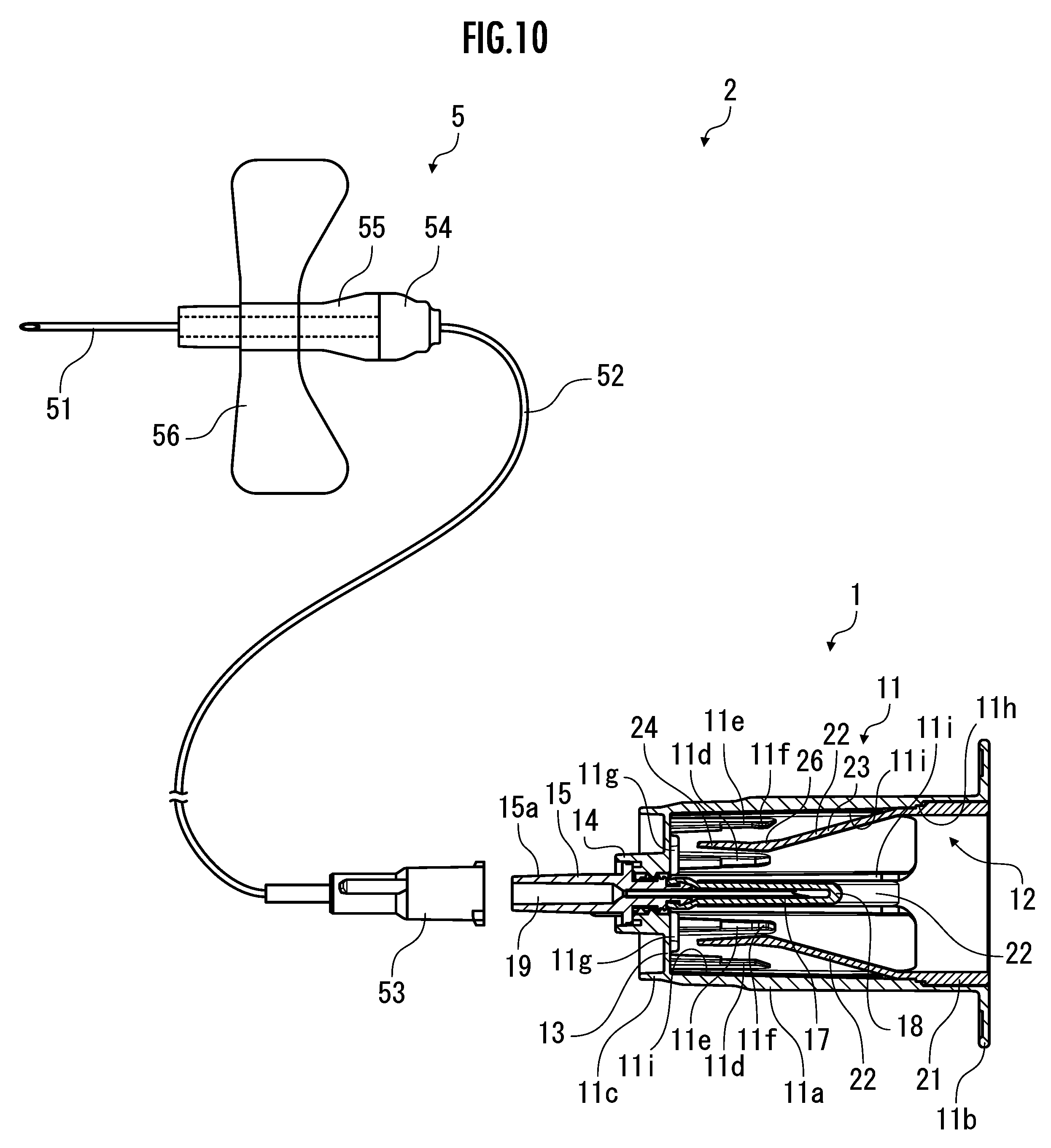
本実施形態の採血キット2は、採血管ホルダー1と、血管に穿刺された状態で生体に固定される採血具5とを備える。採血具5は、鋭利な先端を備えて血管に穿刺される中空の採血針管51と、採血針管51の基端部に接続される可撓性チューブ52と、可撓性チューブ52の基端部に接続されるメスコネクタ53(本発明のホルダー側コネクタ)とを備える。
The
本実施形態では、採血針管51は、可撓性チューブ52の先端部が接続されたハブ54に支持されており、このハブ54には、血管から採血針管51を抜去した後に先端側に向けてスライドさせることで採血針管51の先端を覆う筒状のプロテクタ55が取り付けられている。そして、プロテクタ55には、生体の皮膚等に安定的に固定するための翼状部材56が固定されている。すなわち、本実施形態の採血具5は、例えば本出願人に係る特開2017-196060号公報に開示されたプロテクタ付き医療用針等の翼状針(翼付き針)から構成されている。
In this embodiment, the blood
採血管ホルダー本体11は、底部13の中央部から先端側に向けて突出する突出部14と、突出部14に螺着された針基15とを備える。針基15は、採血管ホルダー本体11の中空部16に突出する先端が鋭利な中空の針管17を支持し、針管17をその全長に亘って被覆する弾性鞘体としてのゴムスリーブ18を備える一方、先端側には針管17に連通する中空部19を備えている。また、針基15の先端部には、オスコネクタ15aが設けられている。
The blood collection
また、採血管ホルダー本体11は、底部13から採血管ホルダー本体11の中空部16に突出する複数の舌状突出片20を備えている。本実施形態において、舌状突出片20は、底部13の周方向において等間隔で4箇所に備えられている。なお、本実施形態の採血管ホルダー本体11は、針管17及びゴムスリーブ18以外の部分が合成樹脂(ポリプロピレン)から構成されている。そして、針管17は、金属(ステンレス鋼)から構成され、ゴムスリーブは、合成ゴム(イソプレンゴム)から構成されている。
The blood collection
採血管ホルダー本体11は、針基15のオスコネクタ15aがメスコネクタ53に嵌合することにより採血具5と接続することができ、このとき針基15の中空部19を介して、可撓性チューブ52と針管17とが連通し、この結果、採血針管51と針管17とが連通する。針基15のオスコネクタ15aとメスコネクタ53との嵌合は、例えばルアーテーパーにより行うことができる。本実施形態では、針基15のオスコネクタ15aをメスコネクタ53内に挿入することで、オスコネクタ15aの外周面のオスルアーテーパーがメスコネクタ53の内周面のメスルアーテーパーと嵌合するようになっている。
The blood collection
採血管ホルダー本体11の外周面には、軸方向に連続する(延在する)複数の滑り止めリブ11aが設けられると共に、開口側の端部(基端部)にフランジ11bが設けられている。また、採血管ホルダー本体11の底部13の外側面(先端側面)の周縁部には先端側に向けて突出する周壁11cが設けられている。本実施形態では、中空部16の軸方向寸法を短縮して真空採血管(図示せず)の片手での挿抜(挿入及び抜去)を容易にする一方、周壁11cを設けることで採血管ホルダー本体11の外周面を軸方向に延長して把持性を向上させている。
The blood collection
保持部材12は、採血管ホルダー本体11の内周面に内嵌される中空円筒状の嵌合部材21と、嵌合部材21から採血管ホルダー本体11の中空部16に突出する複数の圧接部材22を備えている。本実施形態において、圧接部材22は、図2に示すように、舌状突出片20に対応して嵌合部材21の周方向において等間隔で4箇所に備えられている。
The holding
圧接部材22は、嵌合部材21から採血管ホルダー本体11の中空部16の中心軸側に突出する腕状部23と、腕状部23の先端部から採血管ホルダー本体11の内周面側に屈曲する屈曲部24とを備え、嵌合部材21と腕状部23とを接続する第1の補強片25と、腕状部23と屈曲部24とを接続する第2の補強片26とを備えている。また、圧接部材22は、屈曲部24の嵌合部材21の内周側を向く面(内側面)に、係止部27を備えている。
The
より詳細には、腕状部23は、嵌合部材21の先端側(底部13側)の端部の4箇所に設けられた台形板状の台形状部21aの先端から突出するにつれて漸次中心軸に近接するように傾斜して設けられた帯板状の部材である。また、屈曲部24は、腕状部23の先端から突出するにつれて漸次中心軸から離隔するように傾斜して設けられた帯板状の部材である。
More specifically, the
腕状部23及び屈曲部24は、横断面が円弧状に形成され、内側面が中心軸を中心とする円周に沿った凹面となっている。また、腕状部23及び屈曲部24の内側面における幅方向両端の角部には、適宜の丸みが設けられている。さらに、屈曲部24の外側面の先端側には、先端に向けて漸次厚みが減少する傾斜面24aが設けられると共に、この傾斜面24aの先端の角部には、適宜の丸みが設けられている。
The
第1の補強片25は、台形状部21aと腕状部23の間の曲折した部分の谷側となる内側面において台形状部21aと腕状部23に跨って設けられた幅広のリブ状の部材である。同様に、第2の補強片26は、腕状部23と屈曲部24の間の曲折した部分の谷側となる外側面において腕状部23と屈曲部24に跨って設けられた幅広のリブ状の部材である。また、係止部27は、屈曲部24の基端側の内側面から突出する蒲鉾形状の突起である。
The first reinforcing
嵌合部材21の外周面には、周方向の2箇所において軸方向に連続する(延在する)リブ状の位置決め突起21bと、周方向に連続するリング状の抜け止め突起21cが設けられている。位置決め突起21cは、採血管ホルダー本体11の内周面に設けられた凹部と係合し、採血管ホルダー本体11に対して保持部材12を周方向に位置決めするためのものである。また、抜け止め突起21cは、採血管ホルダー本体11の内周面に設けられた凹部と係合し、採血管ホルダー本体11に対して保持部材12を軸方向に位置決めすると共に、採血管ホルダー本体11から保持部材12が脱落するのを防止するためのものである。
The outer peripheral surface of the
なお、本実施形態では、保持部材12は、合成樹脂(ポリプロピレン)から構成されている。また、位置決め突起21bの個数は、特に限定されるものではなく、1箇所にのみ設けるようにしてもよいし、3箇所以上に設けるようにしてもよい。
In this embodiment, the holding
次に、本実施形態の採血管ホルダー1の作用について説明する。
Next, the operation of the blood
本実施形態の採血管ホルダー1では、針基15のオスコネクタ15aがメスコネクタ53に嵌合されることにより採血具5と接続された状態で、例えば、図3に示すように、採血管ホルダー本体11に内嵌された保持部材12の内周側に、真空採血管3aを挿入する。ここで、真空採血管3aは、オーバーキャップタイプであり、ガラス、硬質プラスチック等からなる中空有底筒状体からなる採血管本体31と、採血管本体31の開口端部を閉塞するゴムキャップ32と、採血管本体31及びゴムキャップ32を保護する中空有底筒状体からなる合成樹脂製の外筒管(オーバーキャップ)33とからなる。外筒管33はゴムキャップ32に外嵌される一方、底部にゴムキャップ32の一部を露出する開口部を備えている。
In the blood
保持部材12の内周側に、真空採血管3aを挿入すると、嵌合部材21から採血管ホルダー本体11の中空部16に突出する圧接部材22が真空採血管3aに押圧されて、図3に仮想線示する状態から採血管ホルダー本体11の内周面側に揺動変形する。このとき、圧接部材22の腕状部23と屈曲部24とは、真空採血管3aによる押圧の結果断面視略直線状となっており、それ自体の弾性力により原状(図3に仮想線示する状態)に復帰しようとし、真空採血管3aの外周面に圧接される。
When the vacuum
一方、保持部材12の内周側に、真空採血管3aを挿入すると、ゴムキャップ32がゴムスリーブ18に当接され、さらにゴムスリーブ18を針基15側に向けて押圧する。この結果、針管17がゴムスリーブ18及びゴムキャップ32を貫通して、真空採血管3a内に挿入される一方、ゴムスリーブ18は圧縮され、ゴムキャップ32と針基15との間で蛇腹状に折り畳まれた状態になる。
On the other hand, when the vacuum
針管17が真空採血管3a内に挿入されると、針管17は針基15の中空部19及び可撓性チューブ52を介して採血針管51に連通されているので、採血具5の採血針管51により採血される血液試料が可撓性チューブ52及び針管17を介して真空採血管3a内に導入される。
When the
このとき、前述のように圧縮され、ゴムキャップ32と針基15との間で蛇腹状に折り畳まれた状態となっているゴムスリーブ18は、それ自体の弾性力により原状に復帰しようとして真空採血管3aを開口側(嵌合部材21側)に向けて押圧するので、圧接部材22の圧接により保持されている真空採血管3aが採血管ホルダー本体11から脱落することが懸念される。
At this time, the
しかし、本実施形態の採血管ホルダー1では、前述のように真空採血管3aによる押圧の結果、圧接部材22の腕状部23と屈曲部24とが断面視略直線状となっており、屈曲部24の先端が舌状突出片20に接触することにより、舌状突出片20を採血管ホルダー本体11の内周面側に揺動変形させる。舌状突出片20は、前記のように揺動されるとそれ自体の弾性力により原状に復帰しようとし、屈曲部24の先端を前記採血管の外周面側に向けて押圧する。
However, in the blood
この結果、圧接部材22は、それ自体の弾性力に加えて、舌状突出片20の押圧力により真空採血管3aの外周面に対する圧接が補助されることとなり、より強い力で真空採血管3aを保持することができる。従って、真空採血管3aが圧縮されたゴムスリーブ18により開口側に向けて押圧されたときにも、採血管ホルダー本体11から真空採血管3aが脱落することを防止することができる。
As a result, in addition to the elastic force of the
本実施形態の採血管ホルダー1では、真空採血管3aに所定量の血液試料が貯留されたならば、真空採血管3aを抜去する。このとき、ゴムスリーブ18は真空採血管3aの抜去に伴って原状に復帰し、針管17をその全長に亘って被覆するので、血液試料が針管17から外部に漏出することを防止することができる。
In the blood
また、本実施形態の採血管ホルダー1では、針基15のオスコネクタ15aがメスコネクタ53に嵌合されることにより採血具5と接続された状態で、例えば、図4に示すように、採血管ホルダー本体11に内嵌された保持部材12の内周側に、真空採血管3bを挿入するようにしてもよい。ここで、真空採血管3bは、ゴム栓キャップタイプであり、ガラス、硬質プラスチック等からなる中空有底筒状体からなる採血管本体31と、採血管本体31の開口端部を閉塞するゴムキャップ32とを備えている。
In addition, in the blood
本実施形態の採血管ホルダー1は、ゴム栓キャップタイプの真空採血管3bに対しても、オーバーキャップタイプの真空採血管3aの場合と同様にして、真空採血管3bが圧縮されたゴムスリーブ18により後方に押圧されたときにも、採血管ホルダー本体11から真空採血管3bが脱落することを防止することができる。
The blood
さらに、本実施形態の採血管ホルダー1では、針基15のオスコネクタ15aがメスコネクタ53に嵌合されることにより採血具5と接続された状態で、例えば、図5に示すように、採血管ホルダー本体11に内嵌された保持部材12の内周側に、真空採血管3cを挿入するようにしてもよい。ここで、真空採血管3cは、シールタイプであり、ガラス、硬質プラスチック等からなる中空有底筒状体からなる採血管本体31と、採血管本体31の開口端部を閉塞するシール部材34とを備えている。シール部材34は例えばアルミフィルムからなるシートの中央部にゴム製の弁体35を備えて構成されている。また、採血管本体31は開口端部から外方に延出するフランジ状のフランジ状部36を備えている。なお、フランジ状部36は、採血管本体31に固定された別部材から構成される場合もある。
Furthermore, in the blood
本実施形態の採血管ホルダー1は、シールタイプの真空採血管3cに対しても、オーバーキャップタイプの真空採血管3a及びゴム栓キャップタイプの真空採血管3bの場合と同様にして、真空採血管3cが圧縮されたゴムスリーブ18により後方に押圧されたときにも、採血管ホルダー本体11から真空採血管3cが脱落することを防止することができる。また、シールタイプの真空採血管3cはフランジ状部36を備えるので、フランジ状部36を屈曲部24の係止部27に係止することができ、さらに確実に採血管ホルダー本体11から真空採血管3cが脱落することを防止することができる。
The blood
本実施形態では、採血管ホルダー本体11に舌状突出片20を設けることで、保持部材12全体の厚みやサイズを大きくすることなく適切な保持力を発生させることを可能としている。この結果、真空採血管3a,3b,3cの脱落を確実に防止しながらも、採血管ホルダー本体11をコンパクトに構成することが可能となるため、真空採血管3aの挿抜性及び採血管ホルダー本体11の把持性が阻害されないようになっている。
In this embodiment, by providing the blood collection
また、本実施形態では、屈曲部24は真空採血管3a,3b,3cの挿入がある程度進んだ後に舌状突出片20と接触し、それ以前は挿入抵抗となる弾性力が保持部材12の弾性力のみとなっているため、真空採血管3a,3b,3cの脱落を確実に防止しながらも、真空採血管3a,3b,3cを容易に挿入することが可能となっている。
In addition, in this embodiment, the
さらに、本実施形態では、真空採血管3a,3b,3cの挿入によって押し開かれるように変形する曲折部分に第1の補強片25及び第2の補強片26を設けることで、適切な保持力を発生させながらも、保持部材12をよりコンパクトに構成することが可能となっている。また、保持部材12に係止部27を設けることで、フランジ状部36以外の部分が比較的小径であることから採血管ホルダー本体11に対して傾きやすいシールタイプの真空採血管3cであっても、安定的に保持して脱落を防止することが可能となっている。
In addition, in this embodiment, by providing the first reinforcing
また、本実施形態では、屈曲部24の外側面の先端側に傾斜面24aを設けると共に、この傾斜面24aの先端に丸みを設けることで、舌状突出片20との接触、並びに接触後の保持部材12及び舌状突出片20の変形がスムーズに行われるようにしている。また、腕状部23及び屈曲部24の内側面の幅方向両端に丸みを設けることで、真空採血管3a,3b,3cの外周面に貼付されたラベル等が腕状部23又は屈曲部24に引っ掛かって剥がれたり破損したりするのを防止している。
In addition, in this embodiment, an
なお、舌状突出片20は、真空採血管3a,3b,3cの挿入によって揺動変形した場合に先端部が採血管ホルダー本体11の内周面に接触するように構成されるものであってもよいし、接触しないように構成されるものであってもよい。同様に、圧接部材22は、真空採血管3a,3b,3cの挿入によって揺動変形した場合にいずれかの部分が採血管ホルダー本体11の内周面に接触するように構成されるものであってもよいし、接触しないように構成されるものであってもよい。
The tongue-shaped
また、採血管ホルダー1は、採血管ホルダー本体11の内周面に、長さ方向(軸方向)に延在して真空採血管3a,3b,3cの外周面に当接する例えばリブ状の当接部(図示せず)を備えていてもよい。また、採血管ホルダー1は、採血管ホルダー本体11の内周面に、長さ方向に延在して揺動変形された圧接部材22を収容する(干渉を避ける)例えば溝状の凹部(図示せず)を備えていてもよい。
The blood
このような当接部を備えることで、真空採血管3a,3b,3cが採血管ホルダー本体11に対して傾くのを防止し、針管17を真空採血管3a,3b,3cに適切に貫通させると共に、真空採血管3a,3b,3cを安定的に保持することが可能となる。また、このような凹部を備えることで、保持部材12を設けることによる真空採血管3a,3b,3cの確実な保持を可能としながらも、採血管ホルダー本体11の外径を小さくして把持性を及び操作性を向上させることができる。なお、このような凹部を設ける場合においても、揺動変形された舌状突出片20又は圧接部材22を凹部の底面に接触させるようにしてもよいし、接触させないようにしてもよい。
Providing such an abutment portion prevents the vacuum
また、圧接部材22及び舌状突出片20の個数は、特に限定されるものではなく、任意の個数を採用することができる。また、舌状突出片20は、採血管ホルダー本体11の内周面から突出するものであってもよいし、採血管ホルダー本体11に固定される別部材から構成されるものであってもよい。また、舌状突出片20によって十分な保持力が得られるような場合には、保持部材12において、第1の補強片25、第2の補強片26、又は係止部27を省略するようにしてもよい。
The number of
また、針基15は、突出部14と一体的に構成されるものであってもよい。また、オスコネクタ15aは、針基15とは別個に突出部14に設けられるものであってもよい。また、オスコネクタ15aは、雌ネジが設けられたロック部材を備えるものであってもよい。また、オスコネクタ15aに代えて、血管に穿刺される採血針管を針基15に設けるようにしてもよい。
The
また、採血キット2において、採血具5は、翼状針以外のものであってもよく、可撓性チューブ52を介さずに採血管ホルダー本体11に接続されるものであってもよい。また、採血具5は、可撓性チューブ52を備えず、適宜のコネクタを備えるエクステンションチューブを介して採血管ホルダー本体11に接続されるものであってもよい。
In addition, in the
また、採血管ホルダー本体11における針管17及びゴムスリーブ18以外の部分の材質は、ポリプロピレン以外にも、例えばポリカーボネート、ポリスチレン、アクリルニトリルブタジエンスチレン(ABS樹脂)、ポリエチレンテレフタレート、ポリ塩化ビニル、又はポリメタクリル酸メチル樹脂(アクリル樹脂)等を採用することが可能であり、保持部材12についても同様である。また、ゴムスリーブ18の材質は、イソプレンゴム以外にも、例えばシリコーンゴム、ブタジエンゴム、ブチルゴム、天然ゴム、ウレタンゴム、又はフッ素ゴム等を採用することができる。
The material of the blood collection
次に、採血管ホルダー1及び採血キット2の他の構成例について説明する。なお、以下の説明においては、図1~5に示す構成と同一の構成には同一の符号を付すと共に詳細な説明を省略する。
Next, other configuration examples of the blood
図6は、真空採血管3cのフランジ状部36の外周面に当接する第1の当接部11d及び第2の当接部11eを採血管ホルダー本体11の内周面に設けると共に、圧接部材22に設けた係止部27に代えて第2の当接部11eに係止部11fを設けた場合の一例を示している。図6に示すように、この例の採血管ホルダー1は、図1に示す例と同様に、採血具5を備える採血キット2の構成の一部である。
Figure 6 shows an example in which a
図7は、図6に示す例における採血管ホルダー本体11の説明的断面図である。なお、図7では、針基15、針管17及びゴムスリーブ18の記載を省略している。図7に示すように、第1の当接部11d及び第2の当接部11eは、採血管ホルダー本体11の内周面において中心軸側に向けて突出すると共に、底部13から開口側に向けて軸方向に連続する(延在する)リブ状に構成されている。また、第1の当接部11d及び第2の当接部11eは、採血管ホルダー本体11の周方向における4箇所に配置されると共に、周方向において交互に配置されている。
Figure 7 is an explanatory cross-sectional view of the blood collection
第1の当接部11dは、底部13側が突出量の大きい段付き形状に構成され、中間部分に段差部11d1が設けられている。また、第1の当接部11dの開口側の端部には、開口側に向けて漸次突出量が減少して内周面に繋がる傾斜部11d2が設けられている。同様に、第2の当接部11eは、底部13側が突出量の大きい段付き形状に構成され、中間部分に段差部11e1が設けられている。そして、第2の当接部11eの開口側の端部には、真空採血管3cのフランジ状部36に係止する係止部11fが設けられている。
The
第1の当接部11d及び第2の当接部11eの軸方向の長さは、特に限定されるものではないが、この例では、採血管ホルダー本体11の中空部16の軸方向の長さの凡そ1/3に設定している。
The axial length of the
また、この例では、真空採血管3a,3bの先端面に当接することで真空採血管3a,3bを軸方向に位置決めする第3当接部11gを、底部13の内側面の4箇所に設けている。この第3当接部11gは、開口側に向けて突出し、開口側から見た場合に中空部16の中心軸を中心とする4つの円弧状の突起から構成されている。このような第3当接部11gを設けることで、真空採血管3a,3bを軸方向の適切な位置に配置する共に、針管17の貫通後の真空採血管の3a,3bの傾きを抑制することができる。
In addition, in this example,
さらに、この例では、保持部材12の嵌合部材21の台形状部21a以外の部分を収容する第1の凹部11hと、嵌合部材21の台形状部21aを収容すると共に、揺動した圧接部材22及び舌状突出片20の少なくとも一部を収容する(干渉を避ける)ための第2の凹部11iとを採血管ホルダー本体11の内周面に設けている。上述のように、このような第1の凹部11h及び第2の凹部11iを設けることで、採血管ホルダー本体11の外径を小径化して把持性及び操作性を向上させることができる。また、第1の凹部11h又は第2の凹部11iを設けることで、保持部材12の厚みや形状の設計の自由度が高くなるため、圧接部材22の弾性力を従来よりも大きくし、十分な保持力を発生させることができる。
Furthermore, in this example, a
第1の凹部11hは、採血管ホルダー本体11の内周面の開口側端部において周方向に連続する(延在する)溝状に構成されている。そして、第1の凹部11hの底面には、保持部材12の位置決め突起21cを収容する位置決め凹部11h1と、保持部材12の抜け止め突起21cを収容する抜け止め凹部11h2とが、それぞれ対応する位置に設けられている。
The
第2の凹部11iは、採血管ホルダー本体11の内周面の圧接部材22に対応する位置において第1の凹部11hから底部13側に向けて軸方向に延在する溝状に構成されている。第2の凹部11iをこのように構成することで、真空採血管3a,3b,3cの挿入に伴う揺動の際に大きなモーメントが加わる腕状部23およびこれを支持する嵌合部材21の設計の自由度がより高まるため、圧接部材22の弾性力をより大きくして真空採血管3a,3b,3cの脱落をより確実に防止することができる。また、第2の凹部11iの底面の底部13側には、舌状突出片20に対応して深さを増加させた追加凹部11i1が設けられている。
The
第1の凹部11h及び第2の凹部11iの深さは、特に限定されるものではないが、採血管ホルダー本体11の内周面と嵌合部材21の内周面との間に生じる段差が小さい方が好ましく、内周面と嵌合部材21の内周面が面一となる深さであることがより好ましい。
The depth of the
採血管ホルダー本体11の内周面と嵌合部材21の内周面を面一にすることで、真空採血管3a,3b,3cの挿抜時にこれらの外周面に貼付されたラベルやシールタイプの真空採血管3cのシール部材34が段差に引っ掛かって剥がれたり破損したりするのを防止することができる。
By making the inner circumferential surface of the blood collection
なお、第1の凹部11h及び第2の凹部11iのいずれか一方のみを設けるようにしてもよい。また、第1の凹部11hとして、位置決め凹部11h1及び抜け止め凹部11h2のみを設けるようにしてもよい。また、第2の凹部11iにおいて、追加凹部11i1を省略するようにしてもよい。
It is also possible to provide only one of the
この例ではまた、舌状突出片20の内側面の突端側に突端に向けて漸次厚みが減少する傾斜面20aを設けると共に、この傾斜面20aの先端の角部に適宜の丸みを設けることで、保持部材12との接触、並びに接触後の保持部材12及び舌状突出片20の変形がよりスムーズに行われるようにしている。
In this example, the tip end of the inner surface of the tongue-shaped
また、採血管ホルダー本体11の突出部14には、針基15の雄ネジと螺合する2条の雌ネジ14aが設けられているが、この例では2つのネジ山を互いに軸方向において重ならないように設けることで、樹脂成形の金型の構造を簡素化することを可能としている。
The
図8は、図6に示す例における保持部材12の外観図である。上述のように、この例では、係止部27は省略されている。また、この例では、位置決め突起21bを周方向の4箇所に設けることで、採血管ホルダー本体11への保持部材12の組付けを容易にしている。さらに、この例では、第2の補強片26によって適切な保持力を維持しつつ、第1の補強片25を省略することで、真空採血管3a,3b,3cの挿入開始時の挿入抵抗を軽減するようにしている。
Figure 8 is an external view of the holding
このように、第1の補強片25及び第2の補強片26は、いずれか一方のみが設けられるものであってもよく、このようにすることで、保持部材12による保持力を適宜に調整することができる。なお、圧接部材22毎に第1の補強片25及び第2の補強片26の設け方を異ならせるようにしてもよいし、第1の補強片25及び第2の補強片26を共に省略するようにしてもよい。
In this way, only one of the first reinforcing
図9Aは第1の当接部11dを拡大して示す説明的断面図であり、図9Bは第2の当接部11eを拡大して示す説明的断面図である。図9Aに仮想線示するように、真空採血管3cは、フランジ状部36の先端面が段差部11d1に当接することで軸方向に位置決めされる。また、フランジ状部36の外周面が開口側の低い方の頂面11d3に当接することで、真空採血管3cは半径方向に位置決めされると共に採血管ホルダー本体11に対する傾きが防止される。また、真空採血管3cは、挿入時に傾いていた場合にも傾斜部11d2によってフランジ状部36の外周面が頂面11d3に当接する状態に誘導されるようになっている。
Figure 9A is an explanatory cross-sectional view showing an enlarged view of the
図9Bに仮想線示するように、真空採血管3cは、第2の当接部11eにおいても同様に、フランジ状部36の先端面が段差部11e1に当接することで軸方向に位置決めされ、フランジ状部36の外周面が開口側の低い方の頂面11e3に当接することで、半径方向の位置決め及び採血管ホルダー本体11に対する傾き防止がなされる。そして、係止部11fがフランジ状部36に係止することによって、真空採血管3cの脱落が防止される。
As shown by phantom lines in FIG. 9B, the vacuum
この例では、係止部11fを、頂面11e3からさらに突出するように設けている。また、係止部11fを、中心軸と略平行となるように頂部に設けられた平行面11f1と、平行面11f1の開口側において開口側に向けて漸次突出量が減少する開口側傾斜面11f2と、平行面11f1の底部13側において底部13側に向けて漸次突出量が減少する底部側傾斜面11f3とを有する台形状に構成している。なお、開口側傾斜面11f2は、内周面と繋がるように設けられており、第1の当接部11dの傾斜部11d2と同様の機能を奏する。
In this example, the locking
真空採血管3cの挿入時には、採血管ホルダー本体11及びフランジ状部36を弾性変形させることによって、フランジ状部36に係止部11fを乗り越えさせる必要がある。従って、挿入抵抗は、フランジ状部36の先端側(底部13側)の角部36aが開口側傾斜面11f2に当接している際に増加し、フランジ状部36の基端側(開口側)の角部36bが底部側傾斜面11f3に当接している際に減少することとなる。そして、使用者は、この挿入抵抗の増加からの減少をクリック感として感じることで、真空採血管3cが適切な位置に配置されたことを指先の感覚だけで把握することができる。
When inserting the vacuum
この例では、開口側傾斜面11f2と底部側傾斜面11f3の間に平行面11f1を設けることで、このクリック感を適切に生じさせるようにしている。具体的には、平行面11f1を設けなかった場合、フランジ状部36の先端側の角部36aが開口側傾斜面11f2を越えた後、フランジ状部36は4つの係止部11fの開口側傾斜面11f2と底部側傾斜面11f3の間の角部に挟持されることとなり、真空採血管3cは採血管ホルダー本体11に対して傾きやすい状態となる。真空採血管3cが採血管ホルダー本体11に対して傾いていると、フランジ状部36の基端側の角部36bが4つの係止部11f毎に異なるタイミングで底部側傾斜面11f3と当接する場合があり、クリック感が連続的に生じる結果、真空採血管3cの適切な配置を使用者が把握し難い可能性がある。
In this example, the parallel surface 11f1 is provided between the opening side inclined surface 11f2 and the bottom side inclined surface 11f3 to appropriately generate this clicking sensation. Specifically, if the parallel surface 11f1 is not provided, after the
これに対し、開口側傾斜面11f2と底部側傾斜面11f3の間に平行面11f1を設けることで、フランジ状部36の先端側の角部36aが開口側傾斜面11f2を越えた後の真空採血管3cの傾きを防止することが可能となるため、フランジ状部36の基端側の角部36bを略同じタイミングで4つの係止部11fの底部側傾斜面11f3と当接させて、適切なクリック感を生じさせることができる。
In response to this, by providing a parallel surface 11f1 between the opening side inclined surface 11f2 and the bottom side inclined surface 11f3, it is possible to prevent the vacuum
この例ではさらに、段差部11e1と底部側傾斜面11f3の底部13側の端(頂面11e3との境界)の間の距離D1をフランジ状部36の軸方向寸法D2よりも小さく設定する(換言すれば、段差部11e1から距離D2だけ離れた位置において頂面11e3よりも突出するように底部側傾斜面11f3を設ける)ことで、底部側傾斜面11f3の中心軸に対する傾斜角度θを約5°と小さく設定することを可能としている。距離D1をフランジ状部36の軸方向寸法D2よりも小さく設定することで、フランジ状部36を段差部11e1と底部側傾斜面11f3の間に挟持してフランジ状部36に対する底部側傾斜面11f3の押圧力を高めることが可能となるため、傾斜角度θを小さく設定した場合にも確実に真空採血管3cの脱落を防止することができる。
In this example, the distance D1 between the step 11e1 and the end of the bottom 13 side of the bottom side inclined surface 11f3 (the boundary with the top surface 11e3) is set smaller than the axial dimension D2 of the flange-shaped portion 36 (in other words, the bottom side inclined surface 11f3 is provided so as to protrude from the top surface 11e3 at a position distanced from the step 11e1 by the distance D2), which makes it possible to set the inclination angle θ of the bottom side inclined surface 11f3 with respect to the central axis to a small value of about 5°. By setting the distance D1 smaller than the axial dimension D2 of the flange-shaped
そして、傾斜角度θを小さく設定することで、真空採血管3cの採血管ホルダー1からの抜去時の抵抗を軽減することができる。すなわち、この例の係止部11fによれば、真空採血管3cの脱落の防止と抜去の容易性を両立させることができる。
By setting the inclination angle θ small, it is possible to reduce the resistance when removing the vacuum
なお、係止部11fの形状は、このような台形状に限定されるものではなく、ピラミッド状、ドーム状又は角柱状等、その他の適宜の形状であってもよい。また、例えばクリック感を重要視しない場合には、平行面11f1を有さない形状に係止部11fを構成してもよい。また、開口側傾斜面11f2及び底部側傾斜面11f3は、曲面から構成されるものであってもよい。また、開口側傾斜面11f2及び底部側傾斜面11f3の傾斜角度が特に限定されないことは、言うまでもない。
The shape of the locking
このように、採血管ホルダー本体11の内周面に第1の当接部11d及び第2の当接部11eを設け、第2の当接部11eに係止部11fを設けた場合にも、シールタイプの真空採血管3cを安定的に保持して脱落を防止することができる。また、この場合においても、オーバーキャップタイプの真空採血管3a及びゴム栓キャップタイプの真空採血管3bを、図1に示す例と同様に保持して脱落を防止可能であることは言うまでもない。
In this way, even when the
なお、第1の当接部11d及び第2の当接部11eの個数は、特に限定されるものではなく、任意の個数を採用することができる。また、採血管ホルダー本体11の内周面に第2の当接部11eのみを設けるようにしてもよいし、採血管ホルダー本体11の内周面に第1の当接部11dのみを設け、圧接部材22に係止部27を設けるようにしてもよい。また、第1の当接部11d及び第2の当接部11eを、高い方の頂面11d4、11e4が真空採血管3a,3bの外周面に当接するように構成してもよい。また、係止部11fは、採血管ホルダー本体11の内周面において第2の当接部11eとは別個に設けられるものであってもよい。
The number of the
図10は、図6に示す例において舌状突出片20を省略した場合の一例を示した図である。この例では、舌状突出片20と共に第2の凹部11iの追加凹部11i1を省略している。そして、第2の補強片26の寸法及び形状を適宜に調整すると共に、真空採血管3a,3b,3cの挿入によって圧接部材22が揺動変形した場合に屈曲部24の先端部を第2の凹部11iの底面に接触させることで十分な保持力が得られるようにしている。このように、保持部材12のみによって十分な保持力が得られるような場合には、舌状突出片20を省略するようにしてもよい。
Figure 10 shows an example in which the tongue-shaped
なお、屈曲部24の先端部を第2の凹部11iの底面に接触させるのではなく、圧接部材22に第1の補強片25を追加することで、十分な保持力が得られるようにしてもよい。また、屈曲部24の先端部が採血管ホルダー本体11の内周面における第2の凹部11i以外の部分に接触するように、第2の凹部11iを構成するようにしてもよい。また、係止部11fは、採血管ホルダー本体11の内周面において第2の当接部11eとは別個に設けられるものであってもよいし、圧接部材22に設けられるものであってもよい。また、図示は省略するが、図1に示す例において舌状突出片20を省略するようにしてもよい。
In addition, instead of contacting the tip of the
図11は、オスコネクタ15aに代えてメスコネクタ15bを針基15の先端部に設けた場合の一例を示している。図11に示すように、採血に用いられるシリンジ6は、一般に採血針管の針基(図示せず)を接続するためのオスコネクタ61を先端にそなえているため、このように、針基15にメスコネクタ15bを設けることで、シリンジ6のオスコネクタ61を採血管ホルダー1に直接接続することが可能となる。
Figure 11 shows an example of a case where a
従って、図11に示す採血管ホルダー1によれば、シリンジ6で採血した血液試料を安全に真空採血管3a,3b,3cに分注することができる。シリンジ6に接続した採血針管を真空採血管3a,3b,3cに貫通させて分注する場合、シリンジ6に接続した採血針管が使用者の手指等に誤って刺さる危険性があるが、図11に示す採血管ホルダー1を使用することでこのような針刺しリスクを低減することができる。
Therefore, with the blood
なお、メスコネクタ15bは、針基15とは別個に突出部14に設けられるものであってもよい。また、図11に示す例では、メスコネクタ15bの外周に雄ネジ15b1が設けられているが、雄ネジ15b1を省略するようにしてもよい。また、図1に示す採血管ホルダー1及び図6に示す採血管ホルダー1のいずれにメスコネクタ15bを設けるようにしてもよいことは言うまでもない。
The
図12は、採血具5に代えて接続具7を採血キット2に備えるようにした場合の一例を示している。この例の接続具7は、所定の長さの可撓性チューブ71と、可撓性チューブ71の一端に設けられたメスコネクタ72(本発明のホルダー側コネクタ)と、他端に設けられたメスコネクタ73(本発明のシリンジ側コネクタ)とを備えている。
Figure 12 shows an example of a case where a
図12に示す採血キット2によれば、メスコネクタ72を採血管ホルダー1のオスコネクタ15aに接続し、メスコネクタ73をシリンジ6のオスコネクタ61に接続することで、接続具7を介してシリンジ6を採血管ホルダー1に接続することが可能であるため、図11に示す採血管ホルダー1と同様に、シリンジ6で採血した血液試料を安全に真空採血管3a,3b,3cに分注することができる。また、図12に示す採血キット2によれば、接続具7によって採血管ホルダー1とシリンジ6の相対位置の自由度が増すため、より容易且つ安全に分注を行うことができる。
According to the
なお、可撓性チューブ71の長さは、特に限定されるものではないが、10~300mmであることが好ましい。また、接続具7は、可撓性チューブ71に代えて硬質のチューブ又はパイプ等を備えるものであってもよく、両端にメスコネクタ72,73が設けられた1つの部材から構成されるものであってもよい。
The length of the
また、図1に示す採血管ホルダー1及び図6に示す採血管ホルダー1のいずれと接続具7から図12に示す採血キット2を構成してもよいことは言うまでもない。また、採血キット2は、図11に示すメスコネクタ15bを備える採血管ホルダー1と、可撓性チューブ71の一端にメスコネクタ15bに接続可能なオスコネクタが設けられ、他端にメスコネクタ73が設けられた接続具7とを備えるものであってもよい。
It goes without saying that the
以上、本発明の実施の形態について説明したが、本発明の採血管ホルダー及び採血キットは、上述した実施の形態に限定されるものではなく、本発明の要旨を逸脱しない範囲内において種々変更を加え得ることは勿論である。 Although the embodiment of the present invention has been described above, the blood collection tube holder and blood collection kit of the present invention are not limited to the above-mentioned embodiment, and various modifications can be made without departing from the spirit of the present invention.
例えば、採血管ホルダー1、採血具5及び接続具7の各部の形状及び配置は、上記実施形態で示した形状及び配置に限定されるものではなく、適宜の形状及び配置を採用することができる。また、採血管ホルダー1、採血具5及び接続具7の各部を構成する材質は、特に限定されるものではなく、適宜の材質を採用することができる。
For example, the shapes and arrangements of the blood
また、上述の実施形態において示した作用及び効果は、本発明から生じる最も好適な作用及び効果を列挙したものに過ぎず、本発明による作用及び効果は、これらに限定されるものではない。 Furthermore, the actions and effects shown in the above-mentioned embodiments are merely a list of the most preferable actions and effects resulting from the present invention, and the actions and effects of the present invention are not limited to these.
1…採血管ホルダー、 2…採血キット、 3a,3b,3c…真空採血管、 5…採血具、 6…シリンジ、 7…接続具、 11…採血管ホルダー本体、 11d…第1の当接部、 11e…第2の当接部、 11f,27…係止部、 11g…第3当接部、 12…保持部材、 13…底部、 15…針基、 15b,53,72…メスコネクタ、 16…中空部、 17…針管、 18…ゴムスリーブ、 21…嵌合部材、 22…圧接部材、 51…採血針管。
REFERENCE SIGNS
Claims (3)
前記真空採血管が挿入される筒状の採血管ホルダー本体と、
前記採血管ホルダー本体の先端部に取り付けられ、前記真空採血管を穿刺する針管と、
前記採血管ホルダー本体内に設けられた複数の弾性変形可能な薄板状部材により構成され、前記採血管ホルダー本体の径方向に弾性変形して前記真空採血管の側面を押圧する圧接部材と、
を備え、
前記採血管ホルダー本体の先端部には、前記真空採血管の先端面と当接し、前記真空採血管の進入を止める第3の当接部が形成され、
前記圧接部材と前記第3の当接部は、前記採血管ホルダー本体の周方向に沿って交互に複数配置されている、採血管ホルダー。 A blood collection tube holder for holding a vacuum blood collection tube,
a cylindrical blood collection tube holder body into which the vacuum blood collection tube is inserted;
A needle tube attached to a tip of the blood collection tube holder body and configured to puncture the vacuum blood collection tube;
a pressure contact member that is formed of a plurality of elastically deformable thin plate members provided in the blood collection tube holder body and that elastically deforms in a radial direction of the blood collection tube holder body to press a side surface of the vacuum blood collection tube;
Equipped with
A third contact portion is formed at the tip end of the blood collection tube holder body, the third contact portion being in contact with the tip end surface of the vacuum blood collection tube to stop the vacuum blood collection tube from entering the tip end of the blood collection tube;
A blood collection tube holder, wherein the pressure contact members and the third contact portions are alternately arranged in a plurality of positions along the circumferential direction of the blood collection tube holder body.
3. The blood collection tube holder according to claim 1, wherein the third contact portion is a rib provided upright on an inner surface of a bottom portion of the blood collection tube holder body.
Applications Claiming Priority (4)
| Application Number | Priority Date | Filing Date | Title |
|---|---|---|---|
| JP2019110181 | 2019-06-13 | ||
| JP2019110181 | 2019-06-13 | ||
| JP2020028677A JP7545628B2 (en) | 2019-06-13 | 2020-02-21 | Blood collection tube holder and blood collection kit |
| JP2024130954A JP7731608B2 (en) | 2019-06-13 | 2024-08-07 | Blood collection tube holder and blood collection kit |
Related Parent Applications (1)
| Application Number | Title | Priority Date | Filing Date |
|---|---|---|---|
| JP2024130954A Division JP7731608B2 (en) | 2019-06-13 | 2024-08-07 | Blood collection tube holder and blood collection kit |
Publications (2)
| Publication Number | Publication Date |
|---|---|
| JP7678963B1 true JP7678963B1 (en) | 2025-05-19 |
| JP2025081783A JP2025081783A (en) | 2025-05-27 |
Family
ID=73837171
Family Applications (10)
| Application Number | Title | Priority Date | Filing Date |
|---|---|---|---|
| JP2020028677A Active JP7545628B2 (en) | 2019-06-13 | 2020-02-21 | Blood collection tube holder and blood collection kit |
| JP2020028675A Active JP7465424B2 (en) | 2019-06-13 | 2020-02-21 | Blood collection tube holder and blood collection kit |
| JP2020028678A Active JP7545629B2 (en) | 2019-06-13 | 2020-02-21 | Blood collection tube holder and blood collection kit |
| JP2020028676A Active JP7545627B2 (en) | 2019-06-13 | 2020-02-21 | Blood collection tube holder and blood collection kit |
| JP2021131012A Active JP7415180B2 (en) | 2019-06-13 | 2021-08-11 | Blood collection tube holder and blood collection kit |
| JP2024130954A Active JP7731608B2 (en) | 2019-06-13 | 2024-08-07 | Blood collection tube holder and blood collection kit |
| JP2025037298A Active JP7678962B1 (en) | 2019-06-13 | 2025-03-10 | Blood collection tube holder and blood collection kit |
| JP2025037299A Active JP7678963B1 (en) | 2019-06-13 | 2025-03-10 | Blood collection tube holder and blood collection kit |
| JP2025037297A Active JP7678961B1 (en) | 2019-06-13 | 2025-03-10 | Blood collection tube holder and blood collection kit |
| JP2025132296A Pending JP2025147220A (en) | 2019-06-13 | 2025-08-07 | Blood collection tube holder and blood collection kit |
Family Applications Before (7)
| Application Number | Title | Priority Date | Filing Date |
|---|---|---|---|
| JP2020028677A Active JP7545628B2 (en) | 2019-06-13 | 2020-02-21 | Blood collection tube holder and blood collection kit |
| JP2020028675A Active JP7465424B2 (en) | 2019-06-13 | 2020-02-21 | Blood collection tube holder and blood collection kit |
| JP2020028678A Active JP7545629B2 (en) | 2019-06-13 | 2020-02-21 | Blood collection tube holder and blood collection kit |
| JP2020028676A Active JP7545627B2 (en) | 2019-06-13 | 2020-02-21 | Blood collection tube holder and blood collection kit |
| JP2021131012A Active JP7415180B2 (en) | 2019-06-13 | 2021-08-11 | Blood collection tube holder and blood collection kit |
| JP2024130954A Active JP7731608B2 (en) | 2019-06-13 | 2024-08-07 | Blood collection tube holder and blood collection kit |
| JP2025037298A Active JP7678962B1 (en) | 2019-06-13 | 2025-03-10 | Blood collection tube holder and blood collection kit |
Family Applications After (2)
| Application Number | Title | Priority Date | Filing Date |
|---|---|---|---|
| JP2025037297A Active JP7678961B1 (en) | 2019-06-13 | 2025-03-10 | Blood collection tube holder and blood collection kit |
| JP2025132296A Pending JP2025147220A (en) | 2019-06-13 | 2025-08-07 | Blood collection tube holder and blood collection kit |
Country Status (9)
| Country | Link |
|---|---|
| US (1) | US12194456B2 (en) |
| EP (1) | EP3967229B1 (en) |
| JP (10) | JP7545628B2 (en) |
| CN (1) | CN113993457B (en) |
| ES (1) | ES2963610T3 (en) |
| PL (1) | PL3967229T3 (en) |
| PT (1) | PT3967229T (en) |
| TW (4) | TWI833968B (en) |
| WO (1) | WO2020250858A1 (en) |
Families Citing this family (3)
| Publication number | Priority date | Publication date | Assignee | Title |
|---|---|---|---|---|
| JPWO2022244454A1 (en) * | 2021-05-18 | 2022-11-24 | ||
| CN115486841B (en) * | 2022-09-08 | 2023-05-05 | 丹阳市金晟医用橡塑制品有限公司 | Rubber sheath for blood taking needle capable of improving puncture performance and production device thereof |
| CN119821844B (en) * | 2025-02-07 | 2025-10-03 | 中核四0四成都核技术工程设计研究院有限公司 | A sealing structure and use method of a liquid sampling bottle for radioactive environment |
Citations (7)
| Publication number | Priority date | Publication date | Assignee | Title |
|---|---|---|---|---|
| US4320769A (en) | 1978-05-19 | 1982-03-23 | Becton, Dickinson And Company | Universal holder for blood collecting tubes |
| JP2001527438A (en) | 1997-04-08 | 2001-12-25 | インジェクティムド インコーポレイテッド | Blood collection method and device |
| JP2002291724A (en) | 2001-03-28 | 2002-10-08 | Sekisui Chem Co Ltd | Blood collection tube holder |
| JP2007152083A (en) | 2005-11-08 | 2007-06-21 | Nipro Corp | Blood collection needle set |
| JP3179889U (en) | 2012-09-12 | 2012-11-22 | ニプロ株式会社 | Blood collection line structure |
| US20160100784A1 (en) | 2014-10-10 | 2016-04-14 | ikashmore Pty Ltd. | Sampling device |
| WO2017086867A1 (en) | 2015-11-19 | 2017-05-26 | Hemcheck Sweden Aktiebolag | A protective device for and method of reducing the risk to medical personnel of accidentally puncturing themselves on a hypodermic needle |
Family Cites Families (25)
| Publication number | Priority date | Publication date | Assignee | Title |
|---|---|---|---|---|
| JPS5838941U (en) * | 1981-09-10 | 1983-03-14 | 株式会社三協精機製作所 | Elastic movable contact piece |
| US4731059A (en) * | 1986-10-14 | 1988-03-15 | Medical Safety Products, Inc. | Combination needle shield/needle guard device positively locked onto detachable needle assemblies for an evacuated blood collection system and a hypodermic syringe |
| FR2660544B1 (en) * | 1990-04-10 | 1993-12-24 | Collin Joel | DEVICE FOR TRANSFERRING ARTERIAL OR VENOUS BLOOD FROM A VACUTAINER TO A SYRINGE. |
| JPH0551308U (en) * | 1991-12-13 | 1993-07-09 | 株式会社ニッショー | Blood collection tube for vacuum blood collection tube |
| JPH0716484B2 (en) * | 1992-03-24 | 1995-03-01 | 株式会社ニッショー | Blood collection device adapter |
| JPH05300899A (en) * | 1992-04-24 | 1993-11-16 | Nissho Corp | Adaptor device for blood sampling apparatus |
| JP3144591B2 (en) * | 1992-04-24 | 2001-03-12 | 株式会社ニッショー | Blood collection device adapter |
| JPH07204180A (en) * | 1994-01-21 | 1995-08-08 | Nissho Corp | Blood collection tube holder |
| JPH07327963A (en) * | 1994-06-10 | 1995-12-19 | Sekisui Chem Co Ltd | Vacuum blood collection tube holder |
| US5776076A (en) * | 1996-03-11 | 1998-07-07 | Chen; Long-Hsiung | Safety vacuum syringe for blood sampling |
| JP4053664B2 (en) * | 1998-08-21 | 2008-02-27 | テルモ株式会社 | Blood collection instrument |
| JP2000175888A (en) * | 1998-12-15 | 2000-06-27 | Sekisui Chem Co Ltd | Blood collection tube holder |
| JP2006020934A (en) | 2004-07-09 | 2006-01-26 | Nipro Corp | Blood collection needle |
| JP4945978B2 (en) | 2005-09-15 | 2012-06-06 | 株式会社ジェイ・エム・エス | Vacuum blood collection tube holder |
| ES2331018T3 (en) * | 2005-11-08 | 2009-12-18 | Nipro Corporation | NEEDLE SET FOR BLOOD EXTRACTION. |
| AT503747B1 (en) | 2006-05-18 | 2009-05-15 | Greiner Bio One Gmbh | RECORDING DEVICE FOR A MEDICAL DEVICE |
| JP2008264230A (en) * | 2007-04-20 | 2008-11-06 | Sekisui Chem Co Ltd | Blood collection holder |
| MX366712B (en) * | 2012-07-04 | 2019-07-19 | Equipos Medicos Vizcarra S A Star | Extraction device for collecting blood samples, including a catheter and a safety system. |
| TW201505674A (en) * | 2013-08-06 | 2015-02-16 | Innomedtech Taiwan Llc | Winged blood collection needle with needle stick injury protection |
| JP6614142B2 (en) | 2014-06-18 | 2019-12-04 | ニプロ株式会社 | Blood collection holder |
| AU2017292613B2 (en) * | 2016-07-05 | 2021-11-11 | Retractable Technologies, Inc. | Blood collection tube holder with slide-activated needle retraction |
| JP6880480B2 (en) * | 2016-12-07 | 2021-06-02 | ニプロ株式会社 | Blood collection tube holder |
| ES2675824B1 (en) * | 2017-01-12 | 2019-04-29 | Biotechnology Inst I Mas D Sl | CONTAINER DEVICE FOR THE COLLECTION, STORAGE AND PROCESSING OF BLOOD OR A BLOOD COMPOUND |
| CN206924077U (en) * | 2017-01-19 | 2018-01-26 | 温州美众医学检验所 | Blood taking needle with protection device |
| JP6792789B2 (en) * | 2017-05-26 | 2020-12-02 | 株式会社トップ | adapter |
-
2020
- 2020-02-21 JP JP2020028677A patent/JP7545628B2/en active Active
- 2020-02-21 JP JP2020028675A patent/JP7465424B2/en active Active
- 2020-02-21 JP JP2020028678A patent/JP7545629B2/en active Active
- 2020-02-21 JP JP2020028676A patent/JP7545627B2/en active Active
- 2020-06-08 ES ES20821708T patent/ES2963610T3/en active Active
- 2020-06-08 EP EP20821708.3A patent/EP3967229B1/en active Active
- 2020-06-08 PL PL20821708.3T patent/PL3967229T3/en unknown
- 2020-06-08 US US17/617,910 patent/US12194456B2/en active Active
- 2020-06-08 PT PT208217083T patent/PT3967229T/en unknown
- 2020-06-08 WO PCT/JP2020/022573 patent/WO2020250858A1/en not_active Ceased
- 2020-06-08 CN CN202080042431.8A patent/CN113993457B/en active Active
- 2020-06-11 TW TW109119611A patent/TWI833968B/en active
- 2020-06-11 TW TW109119612A patent/TWI849142B/en active
- 2020-06-11 TW TW109119610A patent/TWI829936B/en active
- 2020-06-11 TW TW109119613A patent/TWI838538B/en active
-
2021
- 2021-08-11 JP JP2021131012A patent/JP7415180B2/en active Active
-
2024
- 2024-08-07 JP JP2024130954A patent/JP7731608B2/en active Active
-
2025
- 2025-03-10 JP JP2025037298A patent/JP7678962B1/en active Active
- 2025-03-10 JP JP2025037299A patent/JP7678963B1/en active Active
- 2025-03-10 JP JP2025037297A patent/JP7678961B1/en active Active
- 2025-08-07 JP JP2025132296A patent/JP2025147220A/en active Pending
Patent Citations (7)
| Publication number | Priority date | Publication date | Assignee | Title |
|---|---|---|---|---|
| US4320769A (en) | 1978-05-19 | 1982-03-23 | Becton, Dickinson And Company | Universal holder for blood collecting tubes |
| JP2001527438A (en) | 1997-04-08 | 2001-12-25 | インジェクティムド インコーポレイテッド | Blood collection method and device |
| JP2002291724A (en) | 2001-03-28 | 2002-10-08 | Sekisui Chem Co Ltd | Blood collection tube holder |
| JP2007152083A (en) | 2005-11-08 | 2007-06-21 | Nipro Corp | Blood collection needle set |
| JP3179889U (en) | 2012-09-12 | 2012-11-22 | ニプロ株式会社 | Blood collection line structure |
| US20160100784A1 (en) | 2014-10-10 | 2016-04-14 | ikashmore Pty Ltd. | Sampling device |
| WO2017086867A1 (en) | 2015-11-19 | 2017-05-26 | Hemcheck Sweden Aktiebolag | A protective device for and method of reducing the risk to medical personnel of accidentally puncturing themselves on a hypodermic needle |
Also Published As
Similar Documents
| Publication | Publication Date | Title |
|---|---|---|
| JP7678963B1 (en) | Blood collection tube holder and blood collection kit | |
| JPS62129061A (en) | Pressure syringe having volume reduced adaptor | |
| WO2015001819A1 (en) | Liquid administration tool | |
| CN102481125A (en) | Disposable Blood Collection Set | |
| WO2020250852A1 (en) | Blood collection tube holder and blood collection kit | |
| WO2020250859A1 (en) | Blood collection tube holder and blood collection kit | |
| JP7563024B2 (en) | Vacuum Tube Holder | |
| WO2020250853A1 (en) | Blood collection tube holder and blood collection kit | |
| JP3683383B2 (en) | Container / Syringe | |
| JP2025012447A (en) | Indwelling needle assembly | |
| JP4464541B2 (en) | Protector | |
| JP2756243B2 (en) | Portable Acupuncture Tube with Acupuncture Holder | |
| JP2021048960A (en) | Needle cap | |
| CN111655312A (en) | Needle device | |
| JP2001096991A (en) | Pushpin |
Legal Events
| Date | Code | Title | Description |
|---|---|---|---|
| A621 | Written request for application examination |
Free format text: JAPANESE INTERMEDIATE CODE: A621 Effective date: 20250310 |
|
| A871 | Explanation of circumstances concerning accelerated examination |
Free format text: JAPANESE INTERMEDIATE CODE: A871 Effective date: 20250310 |
|
| TRDD | Decision of grant or rejection written | ||
| A01 | Written decision to grant a patent or to grant a registration (utility model) |
Free format text: JAPANESE INTERMEDIATE CODE: A01 Effective date: 20250408 |
|
| A61 | First payment of annual fees (during grant procedure) |
Free format text: JAPANESE INTERMEDIATE CODE: A61 Effective date: 20250414 |
|
| R150 | Certificate of patent or registration of utility model |
Ref document number: 7678963 Country of ref document: JP Free format text: JAPANESE INTERMEDIATE CODE: R150 |