JP7674522B2 - ABSORBENT ARTICLE COMPRISING A WAIST PANEL HAVING WEAK JOINTS - Patent application - Google Patents
ABSORBENT ARTICLE COMPRISING A WAIST PANEL HAVING WEAK JOINTS - Patent application Download PDFInfo
- Publication number
- JP7674522B2 JP7674522B2 JP2023573305A JP2023573305A JP7674522B2 JP 7674522 B2 JP7674522 B2 JP 7674522B2 JP 2023573305 A JP2023573305 A JP 2023573305A JP 2023573305 A JP2023573305 A JP 2023573305A JP 7674522 B2 JP7674522 B2 JP 7674522B2
- Authority
- JP
- Japan
- Prior art keywords
- waist
- region
- absorbent article
- edge
- waist panel
- Prior art date
- Legal status (The legal status is an assumption and is not a legal conclusion. Google has not performed a legal analysis and makes no representation as to the accuracy of the status listed.)
- Active
Links
Images


Classifications
-
- A—HUMAN NECESSITIES
- A61—MEDICAL OR VETERINARY SCIENCE; HYGIENE
- A61F—FILTERS IMPLANTABLE INTO BLOOD VESSELS; PROSTHESES; DEVICES PROVIDING PATENCY TO, OR PREVENTING COLLAPSING OF, TUBULAR STRUCTURES OF THE BODY, e.g. STENTS; ORTHOPAEDIC, NURSING OR CONTRACEPTIVE DEVICES; FOMENTATION; TREATMENT OR PROTECTION OF EYES OR EARS; BANDAGES, DRESSINGS OR ABSORBENT PADS; FIRST-AID KITS
- A61F13/00—Bandages or dressings; Absorbent pads
- A61F13/15—Absorbent pads, e.g. sanitary towels, swabs or tampons for external or internal application to the body; Supporting or fastening means therefor; Tampon applicators
- A61F13/15577—Apparatus or processes for manufacturing
- A61F13/15699—Forming webs by bringing together several webs, e.g. by laminating or folding several webs, with or without additional treatment of the webs
-
- A—HUMAN NECESSITIES
- A61—MEDICAL OR VETERINARY SCIENCE; HYGIENE
- A61F—FILTERS IMPLANTABLE INTO BLOOD VESSELS; PROSTHESES; DEVICES PROVIDING PATENCY TO, OR PREVENTING COLLAPSING OF, TUBULAR STRUCTURES OF THE BODY, e.g. STENTS; ORTHOPAEDIC, NURSING OR CONTRACEPTIVE DEVICES; FOMENTATION; TREATMENT OR PROTECTION OF EYES OR EARS; BANDAGES, DRESSINGS OR ABSORBENT PADS; FIRST-AID KITS
- A61F13/00—Bandages or dressings; Absorbent pads
- A61F13/15—Absorbent pads, e.g. sanitary towels, swabs or tampons for external or internal application to the body; Supporting or fastening means therefor; Tampon applicators
- A61F13/56—Supporting or fastening means
- A61F13/58—Adhesive tab fastener elements
- A61F13/60—Adhesive tab fastener elements with release means associated with tab fasteners
-
- A—HUMAN NECESSITIES
- A61—MEDICAL OR VETERINARY SCIENCE; HYGIENE
- A61F—FILTERS IMPLANTABLE INTO BLOOD VESSELS; PROSTHESES; DEVICES PROVIDING PATENCY TO, OR PREVENTING COLLAPSING OF, TUBULAR STRUCTURES OF THE BODY, e.g. STENTS; ORTHOPAEDIC, NURSING OR CONTRACEPTIVE DEVICES; FOMENTATION; TREATMENT OR PROTECTION OF EYES OR EARS; BANDAGES, DRESSINGS OR ABSORBENT PADS; FIRST-AID KITS
- A61F13/00—Bandages or dressings; Absorbent pads
- A61F13/15—Absorbent pads, e.g. sanitary towels, swabs or tampons for external or internal application to the body; Supporting or fastening means therefor; Tampon applicators
- A61F13/45—Absorbent pads, e.g. sanitary towels, swabs or tampons for external or internal application to the body; Supporting or fastening means therefor; Tampon applicators characterised by the shape
- A61F13/49—Absorbent pads, e.g. sanitary towels, swabs or tampons for external or internal application to the body; Supporting or fastening means therefor; Tampon applicators characterised by the shape specially adapted to be worn around the waist, e.g. diapers, nappies
- A61F13/49007—Form-fitting, self-adjusting disposable diapers
- A61F13/49009—Form-fitting, self-adjusting disposable diapers with elastic means
- A61F13/49011—Form-fitting, self-adjusting disposable diapers with elastic means the elastic means is located at the waist region
- A61F13/49012—Form-fitting, self-adjusting disposable diapers with elastic means the elastic means is located at the waist region the elastic means being elastic panels
-
- A—HUMAN NECESSITIES
- A61—MEDICAL OR VETERINARY SCIENCE; HYGIENE
- A61F—FILTERS IMPLANTABLE INTO BLOOD VESSELS; PROSTHESES; DEVICES PROVIDING PATENCY TO, OR PREVENTING COLLAPSING OF, TUBULAR STRUCTURES OF THE BODY, e.g. STENTS; ORTHOPAEDIC, NURSING OR CONTRACEPTIVE DEVICES; FOMENTATION; TREATMENT OR PROTECTION OF EYES OR EARS; BANDAGES, DRESSINGS OR ABSORBENT PADS; FIRST-AID KITS
- A61F13/00—Bandages or dressings; Absorbent pads
- A61F13/15—Absorbent pads, e.g. sanitary towels, swabs or tampons for external or internal application to the body; Supporting or fastening means therefor; Tampon applicators
- A61F13/45—Absorbent pads, e.g. sanitary towels, swabs or tampons for external or internal application to the body; Supporting or fastening means therefor; Tampon applicators characterised by the shape
- A61F13/49—Absorbent pads, e.g. sanitary towels, swabs or tampons for external or internal application to the body; Supporting or fastening means therefor; Tampon applicators characterised by the shape specially adapted to be worn around the waist, e.g. diapers, nappies
- A61F13/49058—Absorbent pads, e.g. sanitary towels, swabs or tampons for external or internal application to the body; Supporting or fastening means therefor; Tampon applicators characterised by the shape specially adapted to be worn around the waist, e.g. diapers, nappies characterised by the modular concept of constructing the diaper
- A61F13/4906—Absorbent pads, e.g. sanitary towels, swabs or tampons for external or internal application to the body; Supporting or fastening means therefor; Tampon applicators characterised by the shape specially adapted to be worn around the waist, e.g. diapers, nappies characterised by the modular concept of constructing the diaper the diaper having an outer chassis forming the diaper and an independent absorbent structure attached to the chassis
- A61F13/49061—Absorbent pads, e.g. sanitary towels, swabs or tampons for external or internal application to the body; Supporting or fastening means therefor; Tampon applicators characterised by the shape specially adapted to be worn around the waist, e.g. diapers, nappies characterised by the modular concept of constructing the diaper the diaper having an outer chassis forming the diaper and an independent absorbent structure attached to the chassis the diaper having one or two waist members forming the diaper waist region and an independent absorbent structure attached to the one or two waist members forming the crotch region
-
- A—HUMAN NECESSITIES
- A61—MEDICAL OR VETERINARY SCIENCE; HYGIENE
- A61F—FILTERS IMPLANTABLE INTO BLOOD VESSELS; PROSTHESES; DEVICES PROVIDING PATENCY TO, OR PREVENTING COLLAPSING OF, TUBULAR STRUCTURES OF THE BODY, e.g. STENTS; ORTHOPAEDIC, NURSING OR CONTRACEPTIVE DEVICES; FOMENTATION; TREATMENT OR PROTECTION OF EYES OR EARS; BANDAGES, DRESSINGS OR ABSORBENT PADS; FIRST-AID KITS
- A61F13/00—Bandages or dressings; Absorbent pads
- A61F13/15—Absorbent pads, e.g. sanitary towels, swabs or tampons for external or internal application to the body; Supporting or fastening means therefor; Tampon applicators
- A61F13/45—Absorbent pads, e.g. sanitary towels, swabs or tampons for external or internal application to the body; Supporting or fastening means therefor; Tampon applicators characterised by the shape
- A61F13/49—Absorbent pads, e.g. sanitary towels, swabs or tampons for external or internal application to the body; Supporting or fastening means therefor; Tampon applicators characterised by the shape specially adapted to be worn around the waist, e.g. diapers, nappies
- A61F13/494—Absorbent pads, e.g. sanitary towels, swabs or tampons for external or internal application to the body; Supporting or fastening means therefor; Tampon applicators characterised by the shape specially adapted to be worn around the waist, e.g. diapers, nappies characterised by edge leakage prevention means
- A61F13/49406—Absorbent pads, e.g. sanitary towels, swabs or tampons for external or internal application to the body; Supporting or fastening means therefor; Tampon applicators characterised by the shape specially adapted to be worn around the waist, e.g. diapers, nappies characterised by edge leakage prevention means the edge leakage prevention means being at the crotch region
- A61F13/4946—Absorbent pads, e.g. sanitary towels, swabs or tampons for external or internal application to the body; Supporting or fastening means therefor; Tampon applicators characterised by the shape specially adapted to be worn around the waist, e.g. diapers, nappies characterised by edge leakage prevention means the edge leakage prevention means being at the crotch region the edge leakage prevention means being an absorbent medium
-
- A—HUMAN NECESSITIES
- A61—MEDICAL OR VETERINARY SCIENCE; HYGIENE
- A61F—FILTERS IMPLANTABLE INTO BLOOD VESSELS; PROSTHESES; DEVICES PROVIDING PATENCY TO, OR PREVENTING COLLAPSING OF, TUBULAR STRUCTURES OF THE BODY, e.g. STENTS; ORTHOPAEDIC, NURSING OR CONTRACEPTIVE DEVICES; FOMENTATION; TREATMENT OR PROTECTION OF EYES OR EARS; BANDAGES, DRESSINGS OR ABSORBENT PADS; FIRST-AID KITS
- A61F13/00—Bandages or dressings; Absorbent pads
- A61F13/15—Absorbent pads, e.g. sanitary towels, swabs or tampons for external or internal application to the body; Supporting or fastening means therefor; Tampon applicators
- A61F13/45—Absorbent pads, e.g. sanitary towels, swabs or tampons for external or internal application to the body; Supporting or fastening means therefor; Tampon applicators characterised by the shape
- A61F13/49—Absorbent pads, e.g. sanitary towels, swabs or tampons for external or internal application to the body; Supporting or fastening means therefor; Tampon applicators characterised by the shape specially adapted to be worn around the waist, e.g. diapers, nappies
- A61F13/494—Absorbent pads, e.g. sanitary towels, swabs or tampons for external or internal application to the body; Supporting or fastening means therefor; Tampon applicators characterised by the shape specially adapted to be worn around the waist, e.g. diapers, nappies characterised by edge leakage prevention means
- A61F13/49466—Absorbent pads, e.g. sanitary towels, swabs or tampons for external or internal application to the body; Supporting or fastening means therefor; Tampon applicators characterised by the shape specially adapted to be worn around the waist, e.g. diapers, nappies characterised by edge leakage prevention means the edge leakage prevention means being at the waist region
-
- A—HUMAN NECESSITIES
- A61—MEDICAL OR VETERINARY SCIENCE; HYGIENE
- A61F—FILTERS IMPLANTABLE INTO BLOOD VESSELS; PROSTHESES; DEVICES PROVIDING PATENCY TO, OR PREVENTING COLLAPSING OF, TUBULAR STRUCTURES OF THE BODY, e.g. STENTS; ORTHOPAEDIC, NURSING OR CONTRACEPTIVE DEVICES; FOMENTATION; TREATMENT OR PROTECTION OF EYES OR EARS; BANDAGES, DRESSINGS OR ABSORBENT PADS; FIRST-AID KITS
- A61F13/00—Bandages or dressings; Absorbent pads
- A61F13/15—Absorbent pads, e.g. sanitary towels, swabs or tampons for external or internal application to the body; Supporting or fastening means therefor; Tampon applicators
- A61F13/56—Supporting or fastening means
- A61F13/58—Adhesive tab fastener elements
- A61F13/581—Tab fastener elements combining adhesive and mechanical fastening
-
- A—HUMAN NECESSITIES
- A61—MEDICAL OR VETERINARY SCIENCE; HYGIENE
- A61F—FILTERS IMPLANTABLE INTO BLOOD VESSELS; PROSTHESES; DEVICES PROVIDING PATENCY TO, OR PREVENTING COLLAPSING OF, TUBULAR STRUCTURES OF THE BODY, e.g. STENTS; ORTHOPAEDIC, NURSING OR CONTRACEPTIVE DEVICES; FOMENTATION; TREATMENT OR PROTECTION OF EYES OR EARS; BANDAGES, DRESSINGS OR ABSORBENT PADS; FIRST-AID KITS
- A61F13/00—Bandages or dressings; Absorbent pads
- A61F13/15—Absorbent pads, e.g. sanitary towels, swabs or tampons for external or internal application to the body; Supporting or fastening means therefor; Tampon applicators
- A61F13/45—Absorbent pads, e.g. sanitary towels, swabs or tampons for external or internal application to the body; Supporting or fastening means therefor; Tampon applicators characterised by the shape
- A61F13/49—Absorbent pads, e.g. sanitary towels, swabs or tampons for external or internal application to the body; Supporting or fastening means therefor; Tampon applicators characterised by the shape specially adapted to be worn around the waist, e.g. diapers, nappies
- A61F2013/49068—Absorbent pads, e.g. sanitary towels, swabs or tampons for external or internal application to the body; Supporting or fastening means therefor; Tampon applicators characterised by the shape specially adapted to be worn around the waist, e.g. diapers, nappies characterized by the shape of the outline
- A61F2013/49074—Absorbent pads, e.g. sanitary towels, swabs or tampons for external or internal application to the body; Supporting or fastening means therefor; Tampon applicators characterised by the shape specially adapted to be worn around the waist, e.g. diapers, nappies characterized by the shape of the outline hourglass; dog bone-shaped
-
- A—HUMAN NECESSITIES
- A61—MEDICAL OR VETERINARY SCIENCE; HYGIENE
- A61F—FILTERS IMPLANTABLE INTO BLOOD VESSELS; PROSTHESES; DEVICES PROVIDING PATENCY TO, OR PREVENTING COLLAPSING OF, TUBULAR STRUCTURES OF THE BODY, e.g. STENTS; ORTHOPAEDIC, NURSING OR CONTRACEPTIVE DEVICES; FOMENTATION; TREATMENT OR PROTECTION OF EYES OR EARS; BANDAGES, DRESSINGS OR ABSORBENT PADS; FIRST-AID KITS
- A61F13/00—Bandages or dressings; Absorbent pads
- A61F13/15—Absorbent pads, e.g. sanitary towels, swabs or tampons for external or internal application to the body; Supporting or fastening means therefor; Tampon applicators
- A61F13/56—Supporting or fastening means
- A61F13/58—Adhesive tab fastener elements
- A61F2013/588—Adhesive tab fastener elements on waist panels
Landscapes
- Health & Medical Sciences (AREA)
- Engineering & Computer Science (AREA)
- Vascular Medicine (AREA)
- Epidemiology (AREA)
- Biomedical Technology (AREA)
- Heart & Thoracic Surgery (AREA)
- Life Sciences & Earth Sciences (AREA)
- Animal Behavior & Ethology (AREA)
- General Health & Medical Sciences (AREA)
- Public Health (AREA)
- Veterinary Medicine (AREA)
- Mechanical Engineering (AREA)
- Manufacturing & Machinery (AREA)
- Absorbent Articles And Supports Therefor (AREA)
Description
本開示は、腰部パネル、より具体的には、脆弱接合部を含む腰部パネルを含む吸収性物品に関するものである。 The present disclosure relates to an absorbent article that includes a waist panel, and more specifically, a waist panel that includes a weakened joint.
組み立てラインに沿って、前進する連続的な材料ウェブに構成要素を加え、かつ/又は別様にこのウェブを修正することによって、例えばおむつ及び他の吸収性物品などの様々なタイプの物品を組み立てることができる。例えば、いくつかのプロセスでは、前進する材料ウェブが、他の前進する材料ウェブと組み合わせられる。他の例では、前進する材料ウェブから作り出された個々の構成要素が、前進する材料ウェブと組み合わせられ、次いで、これらが他の前進する材料ウェブと組み合わせられる。いくつかの例では、前進するウェブ(単数又は複数)から作り出された個々の構成要素は、他の前進するウェブから作り出された他の個々の構成要素と組み合わされる。おむつを製造するために使用される、材料のウェブ及び構成要素部分は、バックシート、トップシート、脚部カフ、ウエストバンド、吸収性コア構成要素、前側耳部及び/又は後側耳部、締結する構成要素、並びに脚部弾性体、バリア脚部カフ弾性体、延伸サイドパネル、及び腰部弾性体などの、様々なタイプの弾性ウェブ及び弾性部を含み得る。いったん望ましい構成部品が組み立てられると、前進するウェブ及び構成部品は、最終的なナイフカットに供されて、ウェブが別個のおむつ又は他の吸収性物品に分離される。 Various types of articles, such as diapers and other absorbent articles, can be assembled by adding components to and/or otherwise modifying a continuous advancing web of material along an assembly line. For example, in some processes, an advancing web of material is combined with other advancing webs of material. In other examples, individual components created from an advancing web of material are combined with an advancing web of material, which are then combined with other advancing webs of material. In some examples, individual components created from an advancing web(s) are combined with other individual components created from other advancing webs. The webs of material and component portions used to manufacture diapers can include various types of elastic webs and elastic portions, such as backsheets, topsheets, leg cuffs, waistbands, absorbent core components, front and/or back ears, fastening components, and leg elastics, barrier leg cuff elastics, stretched side panels, and waist elastics. Once the desired components have been assembled, the advancing web and components are subjected to a final knife cut to separate the web into separate diapers or other absorbent articles.
おむつなどのいくつかの吸収性物品は、ウエストバンドとも称され得る腰部パネルを含む構成要素を有する。いくつかの構成では、ウエストバンドは、弾性フィルムなどの単層の弾性材料として提供されてもよい。いくつかの構成では、ウエストバンドは、不織布などの1つ以上の基材に接合された弾性材料を含み得る弾性積層体として提供されてもよく、弾性材料は、弾性フィルム及び/又は弾性ストランドを含んでもよい。いくつかの組み立て動作では、ウエストバンドは、連続的なトップシート又はバックシートウェブなどの、前進するキャリアウェブに連結され、その間ウエストバンドは延伸状態にある。したがって、ウエストバンドが弛緩すると、キャリアウェブにギャザーが形成されて波形を形成する。得られる積層体は、波形によってウエストバンドが伸長し得る程度に延伸可能である。 Some absorbent articles, such as diapers, have components that include a waist panel, which may also be referred to as a waistband. In some configurations, the waistband may be provided as a single layer of elastic material, such as an elastic film. In some configurations, the waistband may be provided as an elastic laminate, which may include an elastic material bonded to one or more substrates, such as a nonwoven, and the elastic material may include an elastic film and/or elastic strands. In some assembly operations, the waistband is connected to an advancing carrier web, such as a continuous topsheet or backsheet web, while the waistband is in an extended state. Thus, as the waistband relaxes, gathers are formed in the carrier web to form corrugations. The resulting laminate is stretchable to the extent that the corrugations allow the waistband to elongate.
おむつを製造するとき、ウエストバンドは連続的な長さのウエストバンド材料として提供され得、これが延伸され、別個のウエストバンドに切断され、ウエストバンドが延伸状態にある間に、連続的なトップシート又はバックシートウェブなどの、前進するキャリアウェブと接合されることができる。おむつによっては、前側腰部領域に前側ウエストバンドを含み、対向する後側腰部領域に後側ウエストバンドを含むことが望ましい場合がある。いくつかの組み立て動作では、前進するキャリアウェブにウエストバンドの材料片が適用され得、その後、ウエストバンドの材料片は、前進するキャリアウェブが、キャリアウェブを別個のおむつに分離する最終的なナイフ切断に供されたときに、別々の前側ウエストバンド及び後側ウエストバンドに切断される。次に、前側ウエストバンド及び後側ウエストバンドが、同じ連続的な長さのウエストバンド材料から作り出され得る。 When manufacturing diapers, the waistbands may be provided as a continuous length of waistband material, which can be stretched, cut into separate waistbands, and joined to an advancing carrier web, such as a continuous topsheet or backsheet web, while the waistbands are in the stretched state. In some diapers, it may be desirable to include a front waistband in the front waist region and a rear waistband in the opposing rear waist region. In some assembly operations, a piece of waistband material may be applied to the advancing carrier web, which is then cut into separate front and rear waistbands when the advancing carrier web is subjected to a final knife cut that separates the carrier web into separate diapers. The front and rear waistbands may then be produced from the same continuous length of waistband material.
いくつかの構成では、トップシートと接合された領域と、トップシートに接合されていない(取り付けられていない)1つ以上の領域とを有する前側及び/又は後側ウエストバンドを有し、それによってウエストバンドとトップシートとの間にポケットを形成するおむつを提供することが望ましい場合がある。このようなポケットは、身体排出物を収容するのに役立ち、かつ/又は吸収性物品からの漏れを防止するのに役立ち得る。いくつかの構成では、ポケットは、ウエストバンドの3つの縁部に沿ってウエストバンドをトップシートに取り付けることによって形成されてもよく、ウエストバンドの第4の縁部はトップシートに取り付けられないままである。 In some configurations, it may be desirable to provide a diaper having front and/or back waistbands that have areas joined to the topsheet and one or more areas that are not joined (attached) to the topsheet, thereby forming a pocket between the waistband and the topsheet. Such a pocket may help contain body exudates and/or help prevent leakage from the absorbent article. In some configurations, the pocket may be formed by attaching the waistband to the topsheet along three edges of the waistband, with a fourth edge of the waistband remaining unattached to the topsheet.
しかしながら、取り付けられていない縁部を有するウエストバンドを有する吸収性物品を組み立てることは、特定の生産課題を生じさせる場合があり、これは、いくつかの吸収性物品プロセスの高速な生産速度において悪化する場合がある。例えば、特定の製造構成に応じて、ウエストバンドの取り付けられていない縁部は、様々な組立作業を通して前進する間にウエストバンドの前縁部を規定する向きに配置され得る。したがって、いくつかの例では、ウエストバンドが組立作業を通して前進している間に、空気がポケット内に押し込まれることがあり、これにより、ウエストバンドは、トップシートから繰り返し持ち上げられること及び/若しくは分離されること、並びに/又はウエストバンドの形状を変形させることによって、帆又はパラシュートのように作用する。このような繰り返しの持ち上げ及び/又は変形により、ウエストバンドがトップシートから部分的にあるいは全体的に引き剥がされる場合がある。場合によっては、ウエストバンドの取り付けられていない縁部は、トップシートとウエストバンドとの間に新たに塗布された接着剤を有するトップシートのエリアに押し込まれて、取り付けられていない縁部の一部が意図せずにトップシートと接合されることがある。いくつかの構成では、折り畳みプラウなどの様々な組み立て装置に沿って前進するおむつ構成要素に作用する摩擦力が、取り付けられていない縁部を引きずるか又は引っ張り、次にウエストバンドの一部又は全体の永久変形及び/又は除去を引き起こす場合がある。 However, assembling an absorbent article having a waistband with an unattached edge may present certain production challenges, which may be exacerbated at the high production speeds of some absorbent article processes. For example, depending on the particular manufacturing configuration, the unattached edge of the waistband may be oriented to define the front edge of the waistband during progression through various assembly operations. Thus, in some instances, air may be forced into pockets as the waistband progresses through the assembly operations, causing the waistband to act like a sail or parachute by repeatedly lifting and/or separating from the topsheet and/or distorting the shape of the waistband. Such repeated lifting and/or deformation may cause the waistband to partially or entirely peel away from the topsheet. In some cases, the unattached edge of the waistband may be forced into an area of the topsheet that has freshly applied adhesive between the topsheet and the waistband, unintentionally bonding a portion of the unattached edge to the topsheet. In some configurations, frictional forces acting on the diaper components advancing along various assembly equipment, such as folding plows, can drag or pull on unattached edges, which in turn can cause permanent deformation and/or removal of part or all of the waistband.
したがって、使用中にポケットを形成するように、トップシートなどの他のおむつ構成要素から取り付けられていない縁部を備えて構成された腰部パネルを有する吸収性物品を提供することが有益であり、ウエストバンドのある領域は、トップシートなどの吸収性物品構成要素に一時的に接合されて、組み立て中にこのような吸収性物品構成要素からウエストバンドが分離する事象を防止及び/又は低減するのを助けるようにすることができる。 It may therefore be beneficial to provide an absorbent article having a waist panel configured with edges that are unattached from other diaper components, such as a topsheet, to form a pocket during use, and a region of the waistband may be temporarily joined to an absorbent article component, such as a topsheet, to help prevent and/or reduce separation of the waistband from such absorbent article component during assembly.
一形態では、吸収性物品は、前側腰部領域、後側腰部領域、及び前側腰部領域と後側腰部領域との間に配設された股部領域と、第1の腰部縁部、第1の腰部縁部から長手方向に分離された第2の腰部縁部、第1の側縁部、及び第1の側縁部から横方向に分離された第2の側縁部と、トップシート、バックシート、及びトップシートとバックシートとの間に位置決めされた吸収性コアを備えるシャーシと、内側横方向縁部、外側横方向縁部、第1の長手方向縁部、及び第2の長手方向縁部を含む第1の腰部パネルであって、シャーシに接続され、前側腰部領域又は後側腰部領域内に位置付けられる、第1の腰部パネルと、を備え、第1の腰部パネルの第1の領域はシャーシと恒久的に接合され、第1の領域は、第1の腰部パネルの外側横方向縁部に隣接して横方向に延在し、第1の腰部パネルの内側横方向縁部の少なくとも一部分は、シャーシに取り付けられておらず、第1の腰部パネルは、第1の腰部パネルの内側横方向縁部上に、かつ/又は第1の腰部パネルの内側横方向縁部と第1の領域との間に長手方向に位置付けられた脆弱接合部を用いて、シャーシと解放可能に接合されている。 In one embodiment, the absorbent article includes a front waist region, a rear waist region, and a crotch region disposed between the front waist region and the rear waist region, a first waist edge, a second waist edge longitudinally separated from the first waist edge, a first side edge, and a second side edge laterally separated from the first side edge, a chassis including a topsheet, a backsheet, and an absorbent core positioned between the topsheet and the backsheet, and a first waist panel including an inner lateral edge, an outer lateral edge, a first longitudinal edge, and a second longitudinal edge, connected to the chassis and extending from the front waist region to the rear waist region. and a first waist panel positioned in the side waist region or the back waist region, the first region of the first waist panel being permanently joined to the chassis, the first region extending laterally adjacent the outer lateral edge of the first waist panel, at least a portion of the inner lateral edge of the first waist panel being unattached to the chassis, and the first waist panel being releasably joined to the chassis with a weakened joint positioned longitudinally on the inner lateral edge of the first waist panel and/or between the inner lateral edge of the first waist panel and the first region.
別の形態では、吸収性物品は、前側腰部領域、後側腰部領域、及び前側腰部領域と後側腰部領域との間に配設された股部領域と、第1の腰部縁部、第1の腰部縁部から長手方向に分離された第2の腰部縁部、第1の長手方向側縁部、及び第1の長手方向側縁部から横方向に分離された第2の長手方向側縁部と、トップシート、バックシート、及びトップシートとバックシートとの間に位置決めされた吸収性コアを備えるシャーシと、内側横方向縁部、外側横方向縁部、第1の長手方向縁部、及び第2の長手方向縁部を含む腰部パネルであって、シャーシに接続され、前側腰部領域又は後側腰部領域内に位置付けられる、腰部パネルと、を備え、第1の腰部パネルの第1の横方向領域はシャーシと接合され、第1の横方向領域は、腰部パネルの外側横方向縁部に隣接して延在し、腰部パネルの第1の長手方向領域はシャーシと接合され、第1の長手方向領域は、腰部パネルの第1の長手方向縁部に隣接し、腰部パネルの第2の長手方向領域はシャーシに接合され、第2の長手方向領域は、腰部パネルの第2の長手方向縁部に隣接し、第1の腰部パネルの内側横方向縁部の少なくとも一部分はシャーシに取り付けられておらず、腰部パネルは、第1の腰部パネルの内側横方向縁部上に、かつ/又は腰部パネルの内側横方向縁部と第1の横方向領域との間に長手方向に位置付けられ、第1の長手方向領域と第2の長手方向領域との間に横方向に位置付けられた脆弱接合部を用いて、シャーシと解放可能に接合されている。 In another embodiment, an absorbent article includes a chassis including a front waist region, a rear waist region, and a crotch region disposed between the front waist region and the rear waist region, a first waist edge, a second waist edge separated longitudinally from the first waist edge, a first longitudinal side edge, and a second longitudinal side edge separated laterally from the first longitudinal side edge, a topsheet, a backsheet, and an absorbent core positioned between the topsheet and the backsheet, and a waist panel including an inner lateral edge, an outer lateral edge, a first longitudinal edge, and a second longitudinal edge, connected to the chassis and positioned in the front waist region or the rear waist region, the first lateral region of the first waist panel being joined to the chassis, and the second lateral edge being joined to the chassis. The first lateral region extends adjacent to the outer lateral edge of the waist panel, the first longitudinal region of the waist panel is joined to the chassis, the first longitudinal region is adjacent to the first longitudinal edge of the waist panel, the second longitudinal region of the waist panel is joined to the chassis, the second longitudinal region is adjacent to the second longitudinal edge of the waist panel, at least a portion of the inner lateral edge of the first waist panel is not attached to the chassis, and the waist panel is releasably joined to the chassis with a weakened joint located longitudinally on the inner lateral edge of the first waist panel and/or between the inner lateral edge of the waist panel and the first lateral region, and laterally between the first longitudinal region and the second longitudinal region.
更に別の形態では、吸収性物品を組み立てる方法は、キャリア基材を機械方向に前進させるステップと、キャリア基材上に弾性部を位置付けるステップであって、各弾性部は、第1の長手方向縁部と、第1の長手方向縁部から横断方向に分離された第2の長手方向縁部と、を備え、弾性部は、前縁部と、前縁部から機械方向に分離された後縁部と、を更に備える、弾性部を位置付けるステップと、各弾性部の第1の領域をキャリア基材と恒久的に接合するステップであって、第1の領域は、弾性部の前縁部と後縁部との間に位置付けられ、弾性部の内側横方向縁部の一部分は、キャリア基材に取り付けられていないままである、第1の領域を恒久的に接合するステップと、各弾性部の第2の領域をキャリア基材と接合するために、脆弱接合部を適用するステップであって、第2の領域は、弾性部の第1の領域と前縁部との間に位置付けられる、脆弱接合部を適用するステップと、を含む。 In yet another aspect, a method of assembling an absorbent article includes advancing a carrier substrate in a machine direction; positioning elastics on the carrier substrate, each elastic having a first longitudinal edge and a second longitudinal edge separated in a transverse direction from the first longitudinal edge, the elastic further having a leading edge and a trailing edge separated in a machine direction from the leading edge; permanently joining a first region of each elastic to the carrier substrate, the first region being positioned between the leading edge and the trailing edge of the elastic, and a portion of an inner lateral edge of the elastic remaining unattached to the carrier substrate; and applying a weakened joint to join a second region of each elastic to the carrier substrate, the second region being positioned between the leading edge and the leading edge of the elastic.
更に別の形態では、吸収性物品を組み立てる方法は、キャリア基材を機械方向に前進させるステップと、キャリア基材上に弾性部を位置付けるステップであって、各弾性部は、第1の長手方向縁部と、第1の長手方向縁部から横断方向に分離された第2の長手方向縁部と、を備え、弾性部は、前縁部と、前縁部から機械方向に分離された後縁部と、を更に備える、弾性部を位置付けるステップと、各弾性部の第1の領域をキャリア基材と恒久的に接合するステップであって、第1の領域は、弾性部の前縁部と後縁部との間に位置付けられ、弾性部の内側横方向縁部の一部分は、キャリア基材に取り付けられないままである、第1の領域を恒久的に接合するステップと、各弾性部の第2の領域をキャリア基材と接合するために、脆弱接合部を適用するステップであって、第2の領域は、弾性部の第1の領域と前縁部との間に位置付けられる、脆弱接合部を適用するステップと、を含む。 In yet another aspect, a method of assembling an absorbent article includes advancing a carrier substrate in a machine direction; positioning elastics on the carrier substrate, each elastic having a first longitudinal edge and a second longitudinal edge separated in a transverse direction from the first longitudinal edge, the elastic further having a leading edge and a trailing edge separated in a machine direction from the leading edge; permanently joining a first region of each elastic to the carrier substrate, the first region being positioned between the leading edge and the trailing edge of the elastic, and a portion of an inner lateral edge of the elastic remaining unattached to the carrier substrate; and applying a weakened joint to join a second region of each elastic to the carrier substrate, the second region being positioned between the leading edge and the leading edge of the elastic.
更に別の形態では、吸収性物品は、前側腰部領域、後側腰部領域、及び前側腰部領域と後側腰部領域との間に配設された股部領域と、第1の腰部縁部、第1の腰部縁部から長手方向に分離された第2の腰部縁部、第1の側縁部、及び第1の側縁部から横方向に分離された第2の側縁部と、トップシート、バックシート、及びトップシートとバックシートとの間に位置決めされた吸収性コアを備えるシャーシと、シャーシに接続され、前側腰部領域から後側腰部領域まで延在する第1の脚部ガスケット要素及び第2の脚部ガスケット要素と、内側横方向縁部、外側横方向縁部、第1の長手方向縁部、及び第2の長手方向縁部を含む腰部パネルであって、シャーシに接続され、前側腰部領域又は後側腰部領域内に位置付けられる、腰部パネルと、を備え、腰部パネルの第1の領域はシャーシと接合され、第1の領域は、腰部パネルの外側横方向縁部に隣接して横方向に延在し、腰部パネルの内側横方向縁部の少なくとも一部分はシャーシに取り付けられておらず、腰部パネルは、腰部パネルの内側横方向縁部上に、かつ/又は第1の腰部パネルの内側横方向縁部と第1の領域との間に長手方向に位置付けられた脆弱接合部を用いて、シャーシ、第1の脚部ガスケット要素、及び第2の脚部ガスケット要素のうちの少なくとも1つと解放可能に接合されている。 In yet another embodiment, an absorbent article includes a front waist region, a rear waist region, and a crotch region disposed between the front waist region and the rear waist region, a first waist edge, a second waist edge longitudinally separated from the first waist edge, a first side edge, and a second side edge laterally separated from the first side edge, a chassis including a topsheet, a backsheet, and an absorbent core positioned between the topsheet and the backsheet, first and second leg gasket elements connected to the chassis and extending from the front waist region to the rear waist region, an inner lateral edge, an outer lateral edge, a first longitudinal edge, and a second longitudinal edge. A lumbar panel connected to the chassis and positioned in the front waist region or the rear waist region, a first region of the lumbar panel joined to the chassis, the first region extending laterally adjacent the outer lateral edge of the lumbar panel, at least a portion of the inner lateral edge of the lumbar panel being unattached to the chassis, and the lumbar panel being releasably joined to at least one of the chassis, the first leg gasket element, and the second leg gasket element with a weakened joint positioned longitudinally on the inner lateral edge of the lumbar panel and/or between the inner lateral edge of the first waist panel and the first region.
本開示を理解する上で、以下の用語説明が有用であり得る。
本明細書において「吸収性物品」とは、主な機能が汚物及び排泄物を吸収かつ保持することである消費者製品を指すために用いられる。吸収性物品には、生理用ナプキン、タンポン、パンティライナー、陰唇間デバイス、創傷包帯、拭き取り用品、テープ式おむつ及びおむつパンツを含む使い捨ておむつ、再利用可能な外側カバーを有するおむつ用のインサート、成人失禁用おむつ、成人失禁用パッド、並びに成人失禁用パンツが含まれ得る。本明細書で「使い捨て」という用語は、洗濯されること又は他の方法で吸収性物品として再生又は再使用されることが一般に意図されていない吸収性物品を説明するために使用される(例えば、これらは1回の使用後に廃棄されるように意図され、またリサイクル、堆肥化、ないしは別の方法で環境に適合する様式で処分するように構成されてもよい)。
The following explanations of terms may be useful in understanding this disclosure.
"Absorbent articles" are used herein to refer to consumer products whose primary function is to absorb and retain waste and excrement. Absorbent articles may include sanitary napkins, tampons, panty liners, interlabial devices, wound dressings, wipes, disposable diapers, including taped diapers and diaper pants, inserts for diapers with reusable outer covers, adult incontinence diapers, adult incontinence pads, and adult incontinence pants. The term "disposable" is used herein to describe absorbent articles that are generally not intended to be washed or otherwise regenerated or reused as absorbent articles (e.g., they are intended to be discarded after a single use and may be configured to be recycled, composted, or otherwise disposed of in an environmentally compatible manner).
「弾性」、「エラストマー」、又は「エラストマー性」とは、弾性特性を示す材料を指し、これには、その弛緩した初期長さに力を加えると、初期長さの10%を超えて上回る伸長された長さに延伸又は伸長することができ、加えられた力が解放されると、ほぼ初期長さに実質的に回復することになる任意の材料が含まれる。 "Elastic," "elastomer," or "elastomeric" refers to a material exhibiting elastic properties, including any material that, when subjected to a force from its relaxed initial length, can be stretched or elongated to an elongated length that is greater than 10% of the initial length, and will substantially recover to approximately its initial length when the applied force is released.
「圧密」、「圧密化」、及び「圧密化された」とは、第1の延伸された長さから、第1の延伸された長さより小さく、ゼロより大きい、第2の延伸された長さまでの伸長の低減を受ける材料を指す。 "Consolidation," "compacted," and "compacted" refer to a material that undergoes a reduction in elongation from a first stretched length to a second stretched length that is less than the first stretched length and greater than zero.
「弛緩状態」は、加えられた力によって延伸されていないときの材料の長さを画定するものである。 The "relaxed state" defines the length of the material when it is not stretched by an applied force.
本明細書の文脈において、0%の伸長は、Lの弛緩長さを有する弛緩状態の材料を指し、150%の伸長は、材料の2.5倍の弛緩長さLを表す。例えば、100ミリメートルの弛緩長さを有する弾性フィルムは、150%の伸長において250ミリメートルの長さを有することになる。また、100ミリメートルの弛緩長さを有する弾性フィルムは、80%の伸長において180ミリメートルの長さを有することになる。 In the context of this specification, 0% elongation refers to the material in a relaxed state having a relaxed length of L, and 150% elongation represents 2.5 times the relaxed length L of the material. For example, an elastic film having a relaxed length of 100 millimeters will have a length of 250 millimeters at 150% elongation, and an elastic film having a relaxed length of 100 millimeters will have a length of 180 millimeters at 80% elongation.
本明細書の文脈において、60%の収縮は、材料の初期延伸長さLの0.6倍の収縮を表す。例えば、250ミリメートルの初期延伸長さを有する弾性フィルムは、60%の収縮において100ミリメートルの収縮長さを有することになる。また、180ミリメートルの初期延伸長さを有する弾性フィルムは、44%の収縮において100ミリメートルの長さを有することになる。 In the context of this specification, a 60% shrinkage represents a shrinkage of 0.6 times the initial stretched length L of the material. For example, an elastic film having an initial stretched length of 250 millimeters will have a shrinkage length of 100 millimeters at 60% shrinkage. And an elastic film having an initial stretched length of 180 millimeters will have a length of 100 millimeters at 44% shrinkage.
本明細書で使用するとき、「連結された」という用語は、ある要素を他の要素に直接付着させることによって、その要素が別の要素に直接固着される構成、並びにある要素を中間部材に付着させて、その中間部材を他の要素に付着させることによってその要素が別の要素に間接的に固着される構成を包含する。 As used herein, the term "connected" includes configurations in which an element is directly secured to another element by directly attaching the element to the other element, as well as configurations in which an element is indirectly secured to another element by attaching the element to an intermediate member and then attaching the intermediate member to the other element.
本明細書で「基材」という用語は、主として二次元(すなわち、XY面内)であり、その長さ(X方向)及び幅(Y方向)に比べてその厚さ(Z方向)が比較的小さい(すなわち、1/10以下)材料を説明するために用いられる。基材の非限定的な例としては、ウェブ、層(1つ又は複数)又は繊維性材料、不織布、高分子フィルム又は金属箔などのフィルム及び箔が挙げられる。これらの材料は、単独で使用される場合もあり、又は一緒に積層された2つ以上の層を含む場合もある。したがって、ウェブは、基材である。 The term "substrate" is used herein to describe a material that is primarily two-dimensional (i.e., in the XY plane) and whose thickness (Z direction) is relatively small (i.e., 1/10 or less) compared to its length (X direction) and width (Y direction). Non-limiting examples of substrates include webs, layers or layers or films and foils, such as fibrous materials, nonwovens, polymeric films or metal foils. These materials may be used alone or may include two or more layers laminated together. Thus, a web is a substrate.
本明細書で「不織布」という用語は、スパンボンド、メルトブロー、カーディングなどのプロセスによって、連続的な(長い)フィラメント(繊維)及び/又は非連続的な(短い)フィラメント(繊維)から作製された材料を指す。いくつかの構成では、不織布は、限定するものではないが、ポリプロピレン繊維及び/若しくはポリエチレン繊維、並びに/又はポリオレフィンを含むバイコンポーネント繊維を有する不織布を含めて、ポリオレフィン系不織布を含んでもよい。好適な繊維の非限定的な例としては、スパンボンド、スパンレイド、メルトブローン、スパンメルト、溶媒紡糸、電界紡糸、カーディング、フィルムフィブリル化、メルトフィルムフィブリル化、エアレイド、ドライレイド、ウェットレイド短繊維、及び当該技術分野において既知のポリマー繊維の一部又は全体に形成された他の不織布ウェブ材料、並びにこれらの加工可能な組み合わせが挙げられる。不織布は、織られた又は編まれたフィラメントパターンを有さない。様々な坪量を有する不織布が本明細書の方法に従って使用され得ることを理解されたい。例えば、一部の不織布は、少なくとも約8gsm、12gsm、16gsm、20gsm、25gsm、30gsm、40gsm、又は65gsmの坪量を有してもよい。いくつかの不織布は、約8gsm~約65gsmの坪量を有してもよく、具体的には、上記の範囲及びその範囲内あるいはその範囲によって形成される全ての範囲内で、全て1gsm刻みで列挙される。 The term "nonwoven" as used herein refers to materials made from continuous (long) filaments (fibers) and/or discontinuous (short) filaments (fibers) by processes such as spunbonding, meltblowing, carding, etc. In some configurations, the nonwoven may include polyolefin-based nonwovens, including but not limited to nonwovens having polypropylene and/or polyethylene fibers, and/or bicomponent fibers that include polyolefins. Non-limiting examples of suitable fibers include spunbond, spunlaid, meltblown, spunmelt, solvent spun, electrospun, carded, film fibrillated, melt film fibrillated, airlaid, drylaid, wetlaid staple fibers, and other nonwoven web materials formed in part or in whole of polymeric fibers known in the art, as well as processable combinations thereof. Nonwovens do not have a woven or knitted filament pattern. It should be understood that nonwovens having a variety of basis weights may be used according to the methods herein. For example, some nonwoven fabrics may have a basis weight of at least about 8 gsm, 12 gsm, 16 gsm, 20 gsm, 25 gsm, 30 gsm, 40 gsm, or 65 gsm. Some nonwoven fabrics may have a basis weight of about 8 gsm to about 65 gsm, specifically recited in 1 gsm increments within the above ranges and all ranges formed by or within the ranges.
様々な坪量を有するフィルムが、本明細書の方法に従って使用され得ることを理解されたい。例えば、一部のフィルムは、少なくとも約8gsm、12gsm、16gsm、20gsm、25gsm、30gsm、40gsm、又は60gsmの坪量を有してもよい。いくつかのフィルムは、約5gsm~約150gsmの坪量を有してもよく、具体的には、上記の範囲及びその範囲内あるいはその範囲によって形成される全ての範囲内で、全て1gsm刻みで列挙される。 It should be understood that films having a variety of basis weights may be used in accordance with the methods herein. For example, some films may have a basis weight of at least about 8 gsm, 12 gsm, 16 gsm, 20 gsm, 25 gsm, 30 gsm, 40 gsm, or 60 gsm. Some films may have a basis weight of about 5 gsm to about 150 gsm, specifically recited in the above ranges and all ranges therein or formed by the ranges, all in 1 gsm increments.
本明細書で考察される弾性フィルムは、様々な材料及び/又は構成要素を含み得ることを理解されたい。いくつかのエラストマー組成物は、スチレン系ブロックコポリマー、ポリエステル、ポリウレタン、ポリエーテルアミド、及びこれらの組み合わせからなる群から選択される熱可塑性エラストマーを含み得る。好適なスチレン系ブロックコポリマーは、ジブロック、トリブロック、テトラブロック、又は少なくとも1つのスチレンブロックを有するその他のマルチブロックコポリマーであってもよい。例示的なスチレン系ブロックコポリマーとしては、スチレン-ブタジエン-スチレン、スチレン-イソプレン-スチレン、スチレン-エチレン/ブチレン-スチレン、スチレン-エチレン/プロピレン-スチレン等が挙げられる。市販されているスチレン系ブロックコポリマーとしては、KRATON(スチレン系ブロックコポリマー;Kraton Chemical Company(Houston、TX)から入手可能)、SEPTON(スチレン系ブロックコポリマー;Kuraray America,Inc.(New York、NY)から入手可能)、VECTOR(スチレン系ブロックコポリマー;TSRC Dexco Chemical Company(Houston、TX)から入手可能)が挙げられ、使用され得る。更なる市販のエラストマーは、ESTANE(ポリウレタン;Lubrizol,Inc(Ohio)から入手可能)、PEBAX(ポリエーテル系ブロックアミド;Arkema Chemicals(Philadelphia,PA)から入手可能)、及びHYTREL(ポリエステル;DuPont(Wilmington,DE)から入手可能)が挙げられる。 It should be understood that the elastic films discussed herein may include a variety of materials and/or components. Some elastomeric compositions may include a thermoplastic elastomer selected from the group consisting of styrenic block copolymers, polyesters, polyurethanes, polyetheramides, and combinations thereof. Suitable styrenic block copolymers may be diblock, triblock, tetrablock, or other multiblock copolymers having at least one styrenic block. Exemplary styrenic block copolymers include styrene-butadiene-styrene, styrene-isoprene-styrene, styrene-ethylene/butylene-styrene, styrene-ethylene/propylene-styrene, and the like. Commercially available styrenic block copolymers include KRATON (styrenic block copolymer; available from Kraton Chemical Company, Houston, TX), SEPTON (styrenic block copolymer; available from Kuraray America, Inc., New York, NY), VECTOR (styrenic block copolymer; available from TSRC Dexco Chemical Company, Houston, TX), and may be used. Additional commercially available elastomers include ESTANE (a polyurethane; available from Lubrizol, Inc., Ohio), PEBAX (a polyether-based block amide; available from Arkema Chemicals, Philadelphia, PA), and HYTREL (a polyester; available from DuPont, Wilmington, DE).
半結晶性ポリオレフィン又はメタロセンポリオレフィンは、使い捨て吸収性製品において使用され得る。本明細書におけるポリオレフィンエラストマー材料としては、ポリエチレン及びポリプロピレンなどのポリオレフィンの任意のポリマー又はコポリマーが挙げられ得るが、これらに限定されない。エラストマーポリプロピレンの例としては、弾性ランダムポリ(プロピレン/オレフィン)コポリマー、立体不規則性を含有するアイソタクチックポリプロピレン、アイソタクチック/アタクチックポリプロピレンブロックコポリマー、アイソタクチックポリプロピレン/ランダムポリ(プロピレン/オレフィン)コポリマーブロックコポリマー、ステレオブロック弾性ポリプロピレン、シンジオタクチックポリプロピレンブロックポリ(エチレン-co-プロピレン)ブロックシンジオタクチックポリプロピレントリブロックコポリマー、アイソタクチックポリプロピレンブロックレジオレギュラーポリプロピレンブロックアイソタクチックポリプロピレントリブロックコポリマー、ポリエチレンランダム(エチレン/オレフィン)コポリマーブロックコポリマー、リアクタブレンドポリプロピレン、極めて低密度のポリプロピレン(又は、同様な意味合いで、超低密度ポリプロピレン)、メタロセンポリプロピレン、及びこれらのブレンド又は組み合わせが挙げられる。一部のホモポリオレフィン及びランダムコポリマー、並びにExxonMobilから入手可能な商標Vistamaxx(商標)及びDowから入手可能なVERSIFY(商標)によって周知の、このようなランダムコポリマーのブレンドは、弾性性能を示す傾向がある。いくつかの実施形態では、2つ以上のエラストマーをブレンドして、所望の弾性性能を達成し得る。例えば、スチレンブロックコポリマーをポリオレフィン系エラストマーとブレンドさせることができる、又はポリプロピレン系エラストマーをその他のポリオレフィン系エラストマーとブレンドさせることができる。 Semicrystalline or metallocene polyolefins may be used in disposable absorbent products. Polyolefin elastomeric materials herein may include, but are not limited to, any polymer or copolymer of polyolefins such as polyethylene and polypropylene. Examples of elastomeric polypropylenes include elastomeric random poly(propylene/olefin) copolymers, isotactic polypropylene containing stereoirregularity, isotactic/atactic polypropylene block copolymers, isotactic polypropylene/random poly(propylene/olefin) copolymer block copolymers, stereoblock elastomeric polypropylene, syndiotactic polypropylene block poly(ethylene-co-propylene) block syndiotactic polypropylene triblock copolymers, isotactic polypropylene block regioregular polypropylene block isotactic polypropylene triblock copolymers, polyethylene random (ethylene/olefin) copolymer block copolymers, reactor blend polypropylene, very low density polypropylene (or, equivalently, ultra low density polypropylene), metallocene polypropylene, and blends or combinations thereof. Some homopolyolefins and random copolymers, as well as blends of such random copolymers, known by the trademarks Vistamaxx™ available from ExxonMobil and VERSIFY™ available from Dow, tend to exhibit elastic performance. In some embodiments, two or more elastomers may be blended to achieve the desired elastic performance. For example, a styrene block copolymer may be blended with a polyolefin-based elastomer, or a polypropylene-based elastomer may be blended with another polyolefin-based elastomer.
本明細書に記載の吸収性物品の構成要素は、米国特許出願公開第2007/0219521(A1)号に記載されているようなバイオベース含量から少なくとも部分的に構成されてもよい。例えば、超吸収性ポリマー構成成分は、バイオベースのアクリル酸からのそれらの誘導によるバイオベースであってもよい。バイオベースのアクリル酸及び製造方法は、米国特許出願公開第2007/0219521(A1)号、並びに米国特許第8,703,450号、同第9,630,901号、及び同第9,822,197号に更に記載されている。他の構成要素、例えば、不織布及びフィルム構成要素は、バイオベースのポリオレフィン材料を含んでもよい。バイオベースのポリオレフィンは、米国特許出願公開第2011/0139657(A1)号、同第2011/0139658(A1)号、同第2011/0152812(A1)号、及び同第2016/0206774(A1)号、並びに米国特許第9,169,366号において更に考察されている。本開示で使用するための例示的なバイオベースのポリオレフィンは、SHA7260(商標)、SHE150(商標)、又はSGM9450F(商標)(全てBraskem S.A.から入手可能)の呼称で入手可能なポリマーを含む。 Components of the absorbent articles described herein may be at least partially comprised of bio-based content as described in U.S. Patent Application Publication No. 2007/0219521 (A1). For example, the superabsorbent polymer components may be bio-based by their derivation from bio-based acrylic acid. Bio-based acrylic acid and methods of manufacture are further described in U.S. Patent Application Publication No. 2007/0219521 (A1), as well as U.S. Patent Nos. 8,703,450, 9,630,901, and 9,822,197. Other components, such as nonwoven and film components, may include bio-based polyolefin materials. Bio-based polyolefins are further discussed in U.S. Patent Application Publication Nos. 2011/0139657 (A1), 2011/0139658 (A1), 2011/0152812 (A1), and 2016/0206774 (A1), and U.S. Patent No. 9,169,366. Exemplary bio-based polyolefins for use in the present disclosure include polymers available under the designations SHA7260™, SHE150™, or SGM9450F™ (all available from Braskem S.A.).
吸収性物品構成要素は、例えば、ASTM D6866-10の方法Bを使用して、約10%~約100%、約25%~約100%、約40%~約100%、約50%~約100%、約75%~約100%、又は約90%~約100%のバイオベース含有量値を備えてよい。 The absorbent article component may have a biobased content value of about 10% to about 100%, about 25% to about 100%, about 40% to about 100%, about 50% to about 100%, about 75% to about 100%, or about 90% to about 100%, using, for example, ASTM D6866-10, Method B.
本明細書に記載の吸収性物品の構成要素は、それらがリサイクル可能な材料から少なくとも部分的に形成されているかどうかにかかわらず、他の用途のためにリサイクルされてもよい。リサイクルすることができる吸収性物品材料の例は、不織布、フィルム、フラッフパルプ、及び超吸収性ポリマーである。リサイクルプロセスは、吸収性物品を滅菌するためにオートクレーブを使用してもよく、その後、吸収性物品は、細断され、異なる副生成物流に分離されてもよい。例示的な副生成物流は、プラスチック、超吸収性ポリマー、及びパルプなどのセルロース繊維を含むことができる。これらの副生成物流は、肥料、プラスチック製品、紙製品、ビスコース、建築材料、ペット用若しくは病院用ベッドの吸収性パッドの製造において、及び/又は他の用途のために使用することができる。リサイクルを助ける吸収性物品、リサイクルしやすいおむつの設計、並びにリサイクルしやすく、かつバイオベースの構成要素のおむつの設計に関する更なる詳細は、2019年6月27日に公開された米国特許出願公開第2019/0192723(A1)号に開示されている。 The components of the absorbent articles described herein may be recycled for other uses, regardless of whether they are at least partially formed from recyclable materials. Examples of absorbent article materials that can be recycled are nonwovens, films, fluff pulp, and superabsorbent polymers. The recycling process may use an autoclave to sterilize the absorbent articles, which may then be shredded and separated into different by-product streams. Exemplary by-product streams may include plastics, superabsorbent polymers, and cellulose fibers such as pulp. These by-product streams may be used in the manufacture of fertilizers, plastic products, paper products, viscose, building materials, absorbent pads for pets or hospital beds, and/or for other uses. Further details regarding absorbent articles that aid in recycling, designs of diapers that are easy to recycle, and designs of diapers that are easy to recycle and have bio-based components are disclosed in U.S. Patent Application Publication No. 2019/0192723 (A1), published June 27, 2019.
本明細書で「機械方向」(machine direction、MD)という用語は、プロセスを通過する材料の流れの方向を指すために使用される。加えて、材料の相対的配置及び動きは、あるプロセスを通過してそのプロセスの上流からそのプロセスの下流に向かう機械方向に流れているものとして述べることができる。 The term "machine direction" (MD) is used herein to refer to the direction of flow of material through a process. In addition, the relative positioning and movement of material can be described as flowing in the machine direction through a process from upstream in the process to downstream in the process.
本明細書で「横断方向」(cross direction、CD)という用語は、機械方向に対してほぼ垂直な方向を指すために使用される。 The term "cross direction" (CD) is used herein to refer to a direction generally perpendicular to the machine direction.
本開示の態様は、脆弱接合部を含む腰部パネルを有する吸収性物品に関する。以下で考察されるように、吸収性物品は、前側腰部領域と、後側腰部領域と、前側腰部領域と後側腰部領域との間に配設された股部領域と、を備え得る。加えて、吸収性物品は、トップシートと、バックシートと、トップシートとバックシートとの間に位置決めされた吸収性コアと、を備えるシャーシを更に備え得る。腰部パネルは、シャーシに接続され、前側腰部領域又は後側腰部領域内に位置決めされ得る。いくつかの構成では、同様に構成された又は異なる構成の腰部パネルが、前側腰部領域及び後側腰部領域内の両方に位置決めされ得る。腰部パネルは、内側横方向縁部、外側横方向縁部、第1の長手方向縁部、及び第2の長手方向縁部を備え得る。腰部パネルの第1の領域は、シャーシと接合され、第1の領域は、腰部パネルの外側横方向縁部に隣接して横方向に延在し、腰部パネルの内側横方向縁部の少なくとも一部分は、使用中にポケットを形成するようにシャーシに取り付けられていない。更に、腰部パネルは、腰部パネルの内側横方向縁部上に、かつ/又は腰部パネルの内側横方向縁部と第1の領域との間に長手方向に位置付けられた脆弱接合部を用いて、シャーシと解放可能に接合される。脆弱接合部は、接着接合部及び/又は機械的接合部として構成されてもよく、組立作業中に腰部パネルが他の吸収性物品構成要素から分離する事象を防止及び/又は低減するのに役立ち得る。加えて、脆弱接合部はまた、吸収性物品の生産中又は通常の使用中に損壊するように構成されてもよい。脆弱接合部はまた、所定の期間後に劣化して機能しなくなるように構成されてもよい。腰部パネルについては、テープ式おむつ又はパンツ型おむつとして構成され得る吸収性物品の文脈において以下に論じられる。 Aspects of the present disclosure relate to absorbent articles having waist panels that include weakened joints. As discussed below, the absorbent article may include a front waist region, a rear waist region, and a crotch region disposed between the front waist region and the rear waist region. In addition, the absorbent article may further include a chassis including a topsheet, a backsheet, and an absorbent core positioned between the topsheet and the backsheet. The waist panel is connected to the chassis and may be positioned in the front waist region or the rear waist region. In some configurations, similarly or differently configured waist panels may be positioned in both the front waist region and the rear waist region. The waist panel may include an inner lateral edge, an outer lateral edge, a first longitudinal edge, and a second longitudinal edge. The first region of the waist panel is joined to the chassis, the first region extending laterally adjacent the outer lateral edge of the waist panel, and at least a portion of the inner lateral edge of the waist panel is not attached to the chassis to form a pocket during use. Furthermore, the waist panel is releasably joined to the chassis using a weakened joint located on the inner lateral edge of the waist panel and/or longitudinally between the inner lateral edge of the waist panel and the first region. The weakened joint may be configured as an adhesive joint and/or a mechanical joint, and may help prevent and/or reduce the occurrence of separation of the waist panel from other absorbent article components during assembly operations. In addition, the weakened joint may also be configured to break during production or normal use of the absorbent article. The weakened joint may also be configured to deteriorate and fail after a predetermined period of time. Waist panels are discussed below in the context of absorbent articles that may be configured as taped diapers or pant diapers.
「テープ式おむつ」という用語(「開放型おむつ」とも称される)は、着用者に適用される前、包装の際に、互いに締結、予備締結、又は結合されていない初期前側腰部領域及び初期後側腰部領域を有する使い捨て吸収性物品を指す。テープ式おむつは、腰部領域を一緒に締結又は連結することなく、一方の腰部領域の内側が反対の腰部領域の内側と表面同士が接触した状態で、横方向中心線の辺りで折り畳まれてもよい。様々な好適な構成のテープ式おむつの例は、米国特許第5,167,897号、同第5,360,420号、同第5,599,335号、同第5,643,588号、同第5,674,216号、同第5,702,551号、同第5,968,025号、同第6,107,537号、同第6,118,041号、同第6,153,209号、同第6,410,129号、同第6,426,444号、同第6,586,652号、同第6,627,787号、同第6,617,016号、同第6,825,393号、及び同第6,861,571号、並びに米国特許出願公開第2013/0072887(A1)号、同第2013/0211356(A1)号及び同第2013/0306226(A1)号に開示されており、これらは全て参照により本明細書に組み込まれる。 The term "taped diaper" (also referred to as "open diaper") refers to a disposable absorbent article having initial front and back waist regions that are not fastened, prefastened, or joined together during packaging prior to application to a wearer. A taped diaper may be folded about a lateral centerline with the inside of one waist region in surface-to-surface contact with the inside of the opposing waist region without fastening or connecting the waist regions together. Examples of tape diapers of various suitable configurations are shown in U.S. Pat. Nos. 5,167,897, 5,360,420, 5,599,335, 5,643,588, 5,674,216, 5,702,551, 5,968,025, 6,107,537, 6,118,041, 6,153,209, 6,410,129, 6,426, 444, 6,586,652, 6,627,787, 6,617,016, 6,825,393, and 6,861,571, and U.S. Patent Application Publication Nos. 2013/0072887(A1), 2013/0211356(A1), and 2013/0306226(A1), all of which are incorporated herein by reference.
本明細書で「パンツ」(「トレーニングパンツ」、「予め閉じたおむつ」、「おむつパンツ」、「パンツ型おむつ」、及び「プルオンおむつ」とも称される)という用語は、乳児又は成人の着用者のために設計された、外辺部の連続的な腰部開口部及び外辺部の連続的な脚部開口部を有する使い捨て吸収性物品を指す。パンツは、物品が着用者に適用される前に、連続的な又は閉じた腰部開口部及び少なくとも1つの連続的な閉じた脚部開口部を有して構成されてもよい。パンツは、任意の再締結可能な及び/又は恒久的な閉鎖部材(例えば、シーム、熱接合、圧力溶接、接着剤、粘着接合、機械的締結具など)を使用して物品の一部分を一緒に連結することを含むが、これらに限定されない、様々な技術によって予備成形又は予備締結され得る。パンツは、腰部領域において物品の外周部に沿った任意の場所で予備成形され得る(例えば、側部が締結又は継ぎ合わされている、前側腰部が締結又は継ぎ合わされている、後側腰部が締結又は継ぎ合わされている)。様々な構成のおむつパンツの例が、米国特許第4,940,464号、同第5,092,861号、同第5,246,433号、同第5,569,234号、同第5,897,545号、同第5,957,908号、同第6,120,487号、同第6,120,489号、同第7,569,039号、並びに、米国特許出願公開第2003/0233082(A1)号、同第2005/0107764(A1)号、同第2012/0061016(A1)号、同第2012/0061015(A1)号、同第2013/0255861(A1)号、同第2013/0255862(A1)号、同第2013/0255863(A1)号、同第2013/0255864(A1)号及び同第2013/0255865(A1)号に開示されており、これらは全て参照により本明細書に組み込まれる。 The term "pants" (also referred to herein as "training pants", "preclosed diapers", "diaper pants", "pants-type diapers", and "pull-on diapers") refers to a disposable absorbent article having a continuous waist opening at its perimeter and continuous leg openings at its perimeter designed for an infant or adult wearer. A pant may be constructed with a continuous or closed waist opening and at least one continuous closed leg opening before the article is applied to the wearer. A pant may be preformed or prefastened by a variety of techniques, including, but not limited to, joining portions of the article together using any refastenable and/or permanent closure member (e.g., seams, heat bonds, pressure welding, adhesives, cohesive bonds, mechanical fasteners, etc.). A pant may be preformed anywhere along the perimeter of the article in the waist region (e.g., side fastened or seamed, front waist fastened or seamed, back waist fastened or seamed). Examples of diaper pants of various configurations can be found in U.S. Pat. Nos. 4,940,464, 5,092,861, 5,246,433, 5,569,234, 5,897,545, 5,957,908, 6,120,487, 6,120,489, and 7,569,039, as well as U.S. Patent Application Publication Nos. 2003/0233082(A1), 2005/01077, and 2006/0229914. 64(A1), 2012/0061016(A1), 2012/0061015(A1), 2013/0255861(A1), 2013/0255862(A1), 2013/0255863(A1), 2013/0255864(A1) and 2013/0255865(A1), all of which are incorporated herein by reference.
具体的な例示を目的として、図1A及び図1Bは、本開示に従って組み立てられ得る吸収性物品100の例を示す。具体的には、図1Aは、着用者から見て外方を向くおむつの部分が観察者の方に向いている、テープ式おむつ100Tとして構成されている吸収性物品100の平面図の一例を示す。また、図1Bは、着用者に面するおむつの部分が観察者の方に向いているおむつ100の平面図を示す。図1A及び図1Bに示されるテープ式おむつ100Tは、吸収性シャーシ102、第1の後側側部パネル104及び第2の後側側部パネル106、並びに第1の前側側部パネル108及び第2の前側側部パネル110を含む。
For illustrative purposes, FIGS. 1A and 1B show an example of an
図1A及び図1Bに示すように、吸収性物品100及びシャーシ102は各々、第1の腰部領域116、第2の腰部領域118、及び第1の腰部領域と第2の腰部領域との中間に配設された股部領域119を含む。第1の腰部領域116は、前側腰部領域として構成されてもよく、第2の腰部領域118は、後側腰部領域として構成されてもよい。いくつかの実施形態では、前側腰部領域、後側腰部領域、及び股部領域の各々の長さは、吸収性物品100の長さの1/3であり得る。吸収性物品100はまた、第1の腰部領域116内に、横方向に延在する第1の腰部縁部120を含んでもよく、第1の腰部縁部120は、前側腰部縁部として構成されてもよい。加えて、吸収性物品100は、第2の腰部領域118内に、横方向に延在する第2の腰部縁部122を含んでもよく、第2の腰部縁部122は、後側腰部縁部として構成されてもよい。本考察に対する基準枠を提供するため、図1A及び図1Bのおむつ100Tは、長手方向軸線124及び横方向軸線126を伴って示される。長手方向軸線124は、前側腰部縁部120の中点を通って、かつ、後側腰部縁部122の中点を通って、延在し得る。また、横方向軸線126は、第1の長手方向又は右側縁部128の中点を通って、かつ、第2の長手方向又は左側縁部130を通って、延在し得る。
As shown in Figures 1A and 1B, the
図1A及び図1Bに示すように、吸収性物品100は、内側の着用者対向表面132と、外側の衣類対向表面134と、を含む。したがって、以下に記載される吸収性物品の様々な構成要素は各々、内側の着用者対向表面132と、外側の衣類対向表面134と、を含んでもよいことも理解されたい。シャーシ102は、バックシート136及びトップシート138を含んでもよい。シャーシ102はまた、トップシート138の一部とバックシート136との間に配設された吸収性コア142を含む吸収性アセンブリ140を含み得る。下記でより詳細に考察されるように、吸収性物品100はまた、着用者の脚部及び腰部の周りのフィット感を向上させるため、着用者の脚部の周りのフィット感を向上させるために、脚部ガスケット要素、腰部パネル、及び/又はフラップ、例えば、側部パネル及び/又は耳部などの他の特徴部を含んでもよい。
1A and 1B, the
図1A及び図1Bに示すように、シャーシ102の外周部は、第1の長手方向側縁部128、第2の長手方向側縁部130、第1の腰部領域116内に配置された第1の横方向に延在する端縁部144、及び第2の腰部領域118内に配置された第2の横方向に延在する端縁部146によって画定され得る。側縁部128及び130はいずれも、第1の端縁部144と第2の端縁部146との間に長手方向に延在する。図1Aに示すように、横方向に延在する端縁部144及び146は、前側腰部領域116内の横方向に延在する前側腰部縁部120の一部、及び後側腰部領域118内の長手方向に反対側にありかつ横方向に延在する後側腰部縁部122の一部を形成し得る。第1の横方向端縁部144と第2の横方向端縁部146との間の距離は、シャーシ102のピッチ長さ(pitch length、PL)を画定し得る。吸収性物品100が着用者の下部胴体に着用されるとき、前側腰部縁部120及び後側腰部縁部122は、着用者の腰部の一部分を取り囲んでもよい。同時に、側縁部128及び130は、着用者の脚部の少なくとも一部分を取り囲み得る。また股部領域119は概ね、着用者の脚の間に位置決めされてもよく、吸収性コア142は、前側腰部領域116から股部領域119を通って後側腰部領域118まで延在する。
As shown in FIGS. 1A and 1B, the periphery of the
吸収性物品100の一部分又は全体が、横方向に延伸性を有するように製造され得ることもまた理解されるべきである。この追加の延伸性は、着用者が動いている間、吸収性物品100が着用者の身体に適合することを可能にすることに役立つ場合がある。この付加的な延伸性はまた、例えば、様々なサイズの着用者に対して更なる身体被覆率を提供するために、すなわち、個々の着用者に合わせて吸収性物品を仕立てるために、延伸前の特定のサイズを有するシャーシ102を含んだ吸収性物品100のユーザが、吸収性物品100及び/又はシャーシ102の前側腰部領域116、後側腰部領域118、又は両方の腰部領域を延伸させるのを支援し得る。1つ又は複数の腰部領域のそのような延伸は、股部領域が、1つ又は複数の腰部領域より相対的に小さい程度に延在する限り、吸収性物品に概ね砂時計形状を与えることができ、また、物品が着用されたとき、ぴったり調整された外観を物品に付与することができる。
It should also be appreciated that a portion or the entire
前述のように、吸収性物品100は、バックシート136を含んでもよい。バックシート136はまた、シャーシ102の外面134を画定してもよい。バックシート136は、液体(例えば、経血、尿、及び/又は液状の糞便)に対して不透過性であってもよく、薄いプラスチックフィルムから部分的に製造されてもよいが、他の可撓性の液体不透過性材料も使用することができる。バックシート136は、吸収性コアに吸収及び収容された排泄物が、ベッドシーツ、パジャマ、及び下着などの吸収性物品100と接触する物品を湿潤させるのを防止し得る。バックシート136はまた、織布若しくは不織布材料、ポリエチレン若しくはポリプロピレンの熱可塑性フィルムなどの高分子フィルム、並びに/又はフィルム及び不織布材料を含む(例えば、内側フィルム層及び外側不織布層を有する)多層若しくは複合材料を含んでもよい。バックシート136はまた、エラストマーフィルムを含んでもよい。例示のバックシート136は、厚さが約0.012mm(0.5ミル)~約0.051mm(2.0ミル)のポリエチレンフィルムであり得る。例示的なポリエチレンフィルムは、Clopay Corporation(Cincinnati,Ohio)によってBR-120及びBR-121の製品名にて、またTredegar Film Products(Terre Haute,Ind.)によってXP-39385の製品名にて製造されている。バックシート136はまた、より布様の外観を提供するために、エンボス加工及び/又はつや消し仕上げされてもよい。更に、バックシート136は、蒸気を吸収性コアから逃がすことを可能にしながらも(すなわち、バックシートは通気性である)、なお排泄物がバックシート136を通過するのを防ぐことができる。バックシート136のサイズは、吸収性コア142のサイズ及び/又は吸収性物品100の特定の構造又はサイズによって決定されてもよい。
As previously mentioned, the
また先に述べたように、吸収性物品100は、トップシート138を備えてもよい。トップシート138はまた、シャーシ102の内面132の全て又は一部を画定してもよい。トップシート138は、順応性で、柔らかな感触であり、着用者の皮膚に対して非刺激性であってもよい。トップシートは、一方向又は二方向に弾性的に延伸可能であってもよい。更に、トップシート138は、液体透過性であって、その厚さを通して液体(例えば、経血、尿、及び/又は液状の糞便)が浸透可能であり得る。トップシート138は、織布材料及び不織布材料、有孔又はハイドロフォーミング成形された熱可塑性フィルム、有孔不織布、多孔質発泡体、網状発泡体、網状熱可塑性フィルム、及び熱可塑性スクリムなどの、広範囲の材料から製造されてもよい。織布又は不織布材料は、木質繊維若しくは綿繊維などの天然繊維、ポリエステル、ポリプロピレン若しくはポリエチレン繊維などの合成繊維、又はこれらの組み合わせを含むことができる。トップシート138が繊維を含む場合、繊維は、スパンボンド法、カーディング法、湿式法、メルトブローン法、水流交絡法、又は当該技術分野において既知の別の方法で処理されてもよい。
As also mentioned above, the
トップシート138は、嵩高不織布トップシート、有孔フィルムトップシート及び有孔不織布トップシートから選択されてもよい。有孔フィルムトップシートは、身体排泄物に対して透過性であってもよいが、実質的に非吸収性であり、流体がトップシートを通過して戻って着用者の皮膚を再度濡らす傾向が少ないものであってもよい。例示的な有孔フィルムとしては、全て参照により本明細書に組み込まれる、米国特許第5,628,097号、同第5,916,661号、同第6,545,197号及び同第6,107,539号に開示されたものを挙げることができる。 The topsheet 138 may be selected from lofty nonwoven topsheets, apertured film topsheets, and apertured nonwoven topsheets. Apertured film topsheets may be permeable to body exudates, but may be substantially nonabsorbent and have a reduced tendency to allow fluids to pass back through the topsheet and rewet the wearer's skin. Exemplary apertured films may include those disclosed in U.S. Pat. Nos. 5,628,097, 5,916,661, 6,545,197, and 6,107,539, all of which are incorporated herein by reference.
前述のように、吸収性物品100はまた、シャーシ102に連結される吸収性アセンブリ140を含んでもよい。図1A及び図1Bに示すように、吸収性アセンブリ140は、横方向に延在する前側縁部148を前側腰部領域116内に有してもよく、長手方向に反対側にありかつ横方向に延在する後側縁部150を後側腰部領域118内に有してもよい。吸収性アセンブリは、長手方向に延在する右側縁部152を有してもよく、横方向に反対側にありかつ長手方向に延在する左側縁部154を有してもよく、吸収性アセンブリの側縁部152及び154は両方とも、前側縁部148と後側縁部150との間に長手方向に延在してもよい。吸収性アセンブリ140は、1つ以上の吸収性コア142又は吸収性コア層を追加で含んでもよい。吸収性コア142は、トップシート138とバックシート136との間に少なくとも部分的に配設されてもよく、吸収性物品と適合性のある様々なサイズ及び形状で形成されてもよい。本開示の吸収性コアとして使用するための例示的な吸収性構造体は、米国特許第4,610,678号、同第4,673,402号、同第4,888,231号及び同第4,834,735号に記載されており、これらは全て参照により本明細書に組み込まれる。
As previously mentioned, the
いくつかの吸収性コアの実施形態は、低減された量のセルロース系エアフェルト材料を含有する流体貯蔵コアを備えてもよい。例えば、かかるコアは、約40%未満、30%未満、20%未満、10%未満、5%未満、又は更には約1%未満のセルロース系エアフェルト材料を含んでもよい。かかるコアは、主として、少なくとも約60%、70%、80%、85%、90%、95%、又は更には約100%の量で、吸収性ゲル材料を含んでもよく、その場合コアの残部はマイクロファイバ接着剤を含む(適用可能な場合)。かかるコア、マイクロファイバ接着剤、及び吸収性ゲル材料は、米国特許第5,599,335号、同第5,562,646号、同第5,669,894号及び同第6,790,798号、並びに米国特許出願公開第2004/0158212(A1)号及び同第2004/0097895(A1)号に記載されており、それらは全て参照により本明細書に組み込まれる。 Some absorbent core embodiments may comprise a fluid storage core containing a reduced amount of cellulosic airfelt material. For example, such cores may comprise less than about 40%, less than 30%, less than 20%, less than 10%, less than 5%, or even less than about 1% cellulosic airfelt material. Such cores may comprise primarily absorbent gelling material in an amount of at least about 60%, 70%, 80%, 85%, 90%, 95%, or even about 100%, with the remainder of the core comprising microfiber adhesive (where applicable). Such cores, microfiber adhesives, and absorbent gelling materials are described in U.S. Pat. Nos. 5,599,335, 5,562,646, 5,669,894, and 6,790,798, and U.S. Patent Application Publication Nos. 2004/0158212(A1) and 2004/0097895(A1), all of which are incorporated herein by reference.
いくつかの構成では、吸収性アセンブリ140は、トップシート138と吸収性コア142の着用者に面する側との間に配置される獲得システムを含んでもよい。獲得システムは、吸収性コア142と直接接触でき、単一層、又は、着用者の皮膚に面する上方獲得層(本明細書においてはまた、第1の獲得層とも称される)及び着用者の衣類に面する下方獲得層(本明細書においては、第2の獲得層とも称される)などの多層を含み得る。いくつかの構成では、獲得システムは、尿の噴出など、急増する液体を受け取るように機能してもよい。このように、獲得システムは、吸収性コア142が液体を吸収できるまで、液体の一時的なリザーバとしての機能を果たし得る。例示的な獲得システム及び関連する製造プロセスは、米国特許第8,603,277号及び同第8,568,566号、米国特許出願公開第2012/0316046(A1)号及び同第2014/0163504(A1)号に記載されており、これらは全て参照により本明細書に組み込まれる。
In some configurations, the
いくつかの構成では、獲得システムは、化学的に架橋されたセルロース繊維を含み得る。このような架橋セルロース繊維は、様々な吸収特性を有し得る。代表的な化学的に架橋されたセルロース繊維については、米国特許第5,137,537号に開示されている。クエン酸は代表的な架橋剤の1つである。いくつかの実施形態においては、ポリアクリル酸が使用され得る。いくつかの構成では、架橋セルロース繊維は、捲縮されるか、撚り合わされるか、又はカールされてもよく、あるいは、捲縮、撚り合わせ、及びカールを包含するそれらの組み合わせであってもよい。 In some configurations, the acquisition system may include chemically crosslinked cellulose fibers. Such crosslinked cellulose fibers may have a variety of absorbent properties. Exemplary chemically crosslinked cellulose fibers are disclosed in U.S. Pat. No. 5,137,537. Citric acid is an exemplary crosslinking agent. In some embodiments, polyacrylic acid may be used. In some configurations, the crosslinked cellulose fibers may be crimped, twisted, or curled, or combinations thereof including crimped, twisted, and curled.
いくつかの構成では、上方獲得層及び下方獲得層の一方又は両方が、親水性であり得る不織布を含み得る。更に、いくつかの構成では、上方獲得層及び下方獲得層の一方又は両方が化学的に架橋されたセルロース繊維を含んでもよく、これらセルロース繊維は不織布材料の一部を形成しても形成しなくてもよい。いくつかの実施形態では、上方獲得層は、架橋セルロース繊維を有さない不織布を含んでもよく、下方獲得層は、化学的に架橋されたセルロース繊維を含んでもよい。更に、いくつかの構成では、下方獲得層は、天然又は合成ポリマー繊維などの他の繊維と混合された、化学的に架橋されたセルロース繊維を含んでもよい。いくつかの実施形態によれば、このような他の天然又は合成ポリマー繊維としては、表面積の大きな繊維、熱可塑性結合繊維、ポリエチレン繊維、ポリプロピレン繊維、PET繊維、レーヨン繊維、リオセル繊維、及びこれらの混合物を挙げることができる。 In some configurations, one or both of the upper and lower acquisition layers may include a nonwoven fabric, which may be hydrophilic. Additionally, in some configurations, one or both of the upper and lower acquisition layers may include chemically cross-linked cellulose fibers, which may or may not form part of the nonwoven material. In some embodiments, the upper acquisition layer may include a nonwoven fabric without cross-linked cellulose fibers, and the lower acquisition layer may include chemically cross-linked cellulose fibers. Additionally, in some configurations, the lower acquisition layer may include chemically cross-linked cellulose fibers mixed with other fibers, such as natural or synthetic polymeric fibers. According to some embodiments, such other natural or synthetic polymeric fibers may include high surface area fibers, thermoplastic bonded fibers, polyethylene fibers, polypropylene fibers, PET fibers, rayon fibers, lyocell fibers, and mixtures thereof.
本開示と共に使用するように適合され得る例示的な吸収性アセンブリ140、吸収性コア142、及び関連する構成要素は、米国特許第4,610,678号、同第4,673,402号、同第4,888,231号、同第4,834,735号、同第4,888,231号、同第5,260,345号、同第5,387,207号、同第5,397,316号、同第8,603,277号、及び同第8,568,566号、並びに米国特許出願公開第2012/0316046(A1)号及び同第2014/0163504(A1)号に記載されており、これらは全て参照により本明細書に組み込まれる。
Exemplary
テープ式おむつは、着用者に適用される前に、包装されるときに、前側腰部領域及び後側腰部領域が互いに締結、予備締結、又は接続されていない構成で製造され、また消費者に提供され得る。例えば、テープ式おむつ100Tは、腰部領域を一緒に締結又は連結せずに、第1の腰部領域116の内面132が第2の腰部領域118の内面132と表面同士が接触した状態で、横方向中心線の辺りで折り畳まれてもよい。後側側部パネル104及び106並びに/又は前側側部パネル108及び110もまた、腰部領域116及び118の内面132に向かって横方向内方に折り畳まれてもよい。
The taped diaper may be manufactured and provided to the consumer in a configuration in which the front and rear waist regions are not fastened, prefastened, or connected to one another when packaged prior to application to the wearer. For example, the taped
吸収性物品100はまた、吸収性物品が着用者に位置決めされると、閉じた腰部周辺部及び脚部開口部を形成するように、前側腰部領域116及び後側腰部領域118を共に締結することを可能にする、様々な構成の締結要素を含んでもよい。例えば、図1A及び図1Bに示すように、吸収性物品100は、それぞれ、第1の後側側部パネル104及び第2の後側側部パネル106と接続された、タブとも称される、第1の締結部材162及び第2の締結部材164を含んでもよい。吸収性物品はまた、第1の前側側部パネル108及び第2の前側側部パネル110を含んでもよく、それらは、締結部材を含んでも含まなくてもよい。
The
図1A及び図1Bを続けて参照すると、各側部パネル104、106及び/又は締結部材162及び164は、前側腰部領域116若しくは後側腰部領域118のうちの1つにおいて、側縁部128及び130から横方向内方に、シャーシ102の一部を形成してもよく、又はそのシャーシに直接若しくは間接的に、恒久的に接合、接着、ないしは別の方法で連結されてもよい。代替的に、締結部材162、164は、第1の後側パネル104及び第2の後側パネル106、並びに/又は第1の前側側部パネル108及び第2の前側側部パネル110の一部分を形成し得るか、あるいは第1の後側パネル104及び第2の後側パネル106の遠位縁部に若しくは遠位縁部に隣接して、並びに/又は第1の前側側部パネル108及び第2の前側側部パネル110の遠位縁部に若しくは遠位縁部に隣接して、直接若しくは間接的に、恒久的に接合、接着、ないしは別の方法で連結され得る。締結部材及び/又は側部パネルは、例えば、参照により本明細書に組み込まれる米国特許第7,371,302号に開示されているものなど、様々な方式で組み立てられ得ることを理解されたい。締結部材162、164及び/又は側部パネル104、106、108、110はまた、例えば、参照により本明細書に組み込まれる米国特許第5,702,551号に開示されているものなど、例えば、接着接合、音波接合、圧力接合、熱接合、又はこれらの組み合わせなどの様々な方式で、シャーシ102の側縁部128及び130において、又はそれらに隣接して、恒久的に接合又は連結されてもよい。
With continued reference to Figures 1A and 1B, each
次に図1Bを参照すると、第1の締結部材162及び/又は第2の締結部材164は、様々なタイプの取り外し可能に係合できる締結具を含んでもよい。第1の締結部材162及び/又は第2の締結部材164はまた、様々なタイプの再締結可能な締結構造を含んでもよい。例えば、第1の締結部材162及び第2の締結部材164は、フック・ループ式締結具、フック・フック式締結具、マクロ締結具、ボタン、スナップ、タブ及びスロット締結具、テープ締結具、接着剤締結具、粘着性締結具、磁気締結具、両性型締結具などの形式の、機械的締結具166を含んでもよい。締結システム及び/又は締結部材162、164のいくつかの例は、米国特許第3,848,594号、同第4,662,875号、同第4,846,815号、同第4,894,060号、同第4,946,527号、同第5,151,092号、同第5,221,274号、同第5,242,436号、同第6,251,097号、同第6,669,618号、同第6,432,098号、米国特許出願公開第2007/0078427(A1)号及び同第2007/0093769(A1)号、及び米国特許出願第16/685,230号で考察されており、これらは全て参照によって本明細書に組み込まれる。
1B, the
上述のように、締結部材162及び164は、様々な材料から構築されていてもよく、積層構造として構築されていてもよい。締結部材162及び164はまた、吸収性物品100の別の部分と、取り外し可能に及び/又は再締結可能に、係合又は接続するように適合されてもよい。例えば、図1Aに示すように、吸収性物品100は、第1の腰部領域116内に、ランディングゾーンと称されることもある接続ゾーン168を含み得る。したがって、テープ式吸収性物品100が着用者に配置されると、締結部材162及び164は、着用者の腰部の周囲で引っ張られ、第1の腰部領域116にある接続ゾーン168と接続されて、閉じた腰部周辺部及び一対の横方向に反対側にある脚部開口部を形成してもよい。接続ゾーンは、吸収性物品のシャーシ102と接続されている別の基材から構築されてもよいことを理解されたい。いくつかの実施形態では、接続ゾーンは、参照により本明細書に組み込まれる米国特許第5,735,840号及び同第5,928,212号に記載されているものなど、吸収性物品100のバックシート136の一部として一体化して形成されてもよく、あるいは第1の前側パネル108及び第2の前側パネル110の一部として形成されてもよい。
As mentioned above, the
引き続き図1Bを参照すると、吸収性物品100はまた、脚部ガスケット要素156を含み得る。脚部ガスケット要素156は、脚部カフ、脚部バンド、サイドフラップ、バリヤカフ、弾性カフ又はガスケットカフであり得、場合によってはそのように称されることが理解されよう。脚部ガスケット要素156は、脚部領域における身体排泄物の漏れを低減するのに役立つように様々な方式で弾性化されてもよく、構成されてもよい。例示的な脚部ガスケット要素156には、米国特許第3,860,003号、同第4,909,803号、同第4,695,278号、同第4,795,454号、同第4,704,115号、及び米国特許出願公開第2009/0312730(A1)号に記載されているものが挙げられ得、それらは全て参照により本明細書に組み込まれる。
Continuing to refer to FIG. 1B, the
図1Bに示されるように、吸収性物品100は、着用者に向かって内方に面し、かつ着用者に接触する、シャーシ102の内面132上に配設されている、長手方向に延在しかつ横方向に対向する脚部ガスケット要素156を含んでもよい。各脚部ガスケット要素156は、第1の側縁部157及び第2の側縁部159を有し得、第1の側縁部157は、第2の側縁部159の横方向内側に位置決めされている。脚部ガスケット要素156はまた、吸収性アセンブリ140と重なり合ってもよく、第1の側縁部157は、吸収性アセンブリ140のそれぞれの側縁部152及び154の横方向内向きに延在する。いくつかの構成では、脚部ガスケット要素156は、吸収性アセンブリ140と重なり合わなくてもよい。脚部ガスケット要素156は、様々な方式で、例えば、シャーシ102の一部を横方向に、内方に、すなわち、長手方向軸線124へ向かって折り畳み、シャーシ102のそれぞれの側部ガスケット要素と側縁部128及び130との両方を形成することなどによって、形成され得ることを理解されたい。別の例では、脚部ガスケット要素156は、シャーシ102の対応する側縁部の各々に又はそれに隣接して追加の1つ又は複数の層をシャーシに取り付けることによって形成されてもよい。脚部ガスケット要素156の各々は、前側腰部領域116内の脚部ガスケット要素取り付けゾーン、及び後側腰部領域118内の脚部ガスケット要素取り付けゾーンにおいて、シャーシ及び/又は吸収性アセンブリ140の内面132に連結されてもよい。脚部ガスケット要素156は、吸収性物品100と同一の長手方向範囲まで延在してもよく、又は代替的に、脚部ガスケット要素156は、吸収性物品100よりも狭い長手方向範囲を有してもよい。いくつかの構成では、脚部ガスケット要素は、内側カフ、外側カフ、又は内側カフと外側カフとの両方を画定するように構成され得る。
As shown in FIG. 1B, the
吸収性物品100はまた、図1Bに示されるように、1つ以上の腰部パネル158を含み得る。腰部パネル158は、改善されたフィット感及び封じ込めを提供し得るものであり、また、着用者の腰部に動的に適合するように弾性的に拡張及び収縮し得る、吸収性物品100の一部分又はゾーンであってもよい。吸収性物品100はまた、例えば、第1の腰部領域116内に位置決めされた第1のパネル158aを有する複数の腰部パネル158と、第2の腰部領域118内に位置決めされた第2のパネル158bと、を含んでもよいが、他の構成が、単一の腰部パネル158を用いて構成されてもよい。腰部パネル158は、全て参照により本明細書に組み込まれる、米国特許第4,515,595号及び同第5,151,092号、並びに米国特許出願第16/864,267号、同第16/864292号、同第17/029,211号、及び同第17/029,486号に記載されている構成などのいくつかの異なる構成で構築されてもよい。
The
本明細書の腰部パネル158は、様々な方式で構成されてもよく、例えば、弾性フィルム及び/又はストランドなどの1つ以上の弾性材料を含み得ることを理解されたい。例えば、腰部パネル158は、弾性フィルムの単層として構成され得る。いくつかの構成では、腰部パネル158は、2つ以上の基材の積層体として構成され得る。例えば、腰部パネル158は、2つ以上の不織布基材間に接合された弾性フィルムとして構成されてもよく、かつ/又は1つ以上の不織布基材と接合されてもよい。例えば、腰部パネル158は、単一の不織布基材と接合された弾性フィルムを備えた二層積層体として構成されてもよい。別の例では、腰部パネル158は、2つ以上の基材間に接合された弾性フィルムとして構成されてもよく、基材は不織布を含んでもよい。腰部パネル158の不織布基材は、同じか若しくは異なる材料及び/又は坪量であり得、エラストマー不織布又は非弾性不織布として構成され得ることも理解されたい。いくつかの構成では、腰部パネル158の1つ以上の不織布基材は、トップシート138、バックシート136、及び/又は脚部ガスケット要素156の1つ以上の不織布基材と同じか若しくは異なる材料及び/又は坪量であり得る。
It should be understood that the
本明細書の腰部パネル158は、様々な方式で形成され得、様々な方式で互いに接合され、異なる又は同一の接合パターンを有する様々な構成要素を含み得ることを理解されたい。例えば、本明細書の腰部パネル158は、延伸状態にある少なくとも1つの不織布と接合された弾性フィルムの積層体を含み得る。例えば、図17及び図18は、第1の基材402と、第2の基材410と、第1の基材402と第2の基材410との間に位置決めされた弾性フィルム408とを含む積層体400として構成された腰部パネル158の断面図を示し、第1の基材402及び/又は第2の基材410は、上で考察されたように不織布として構成され得る。いくつかの構成では、積層体は、連続的に接合されても、不連続的に接合されてもよい。いくつかの構成では、積層体は、複数の個々の接合部位と接合され得るが、それらの接合部位は、視覚的に識別可能なパターンを形成してもよく、あるいは形成しなくてもよい。腰部パネル158の第1の基材402及び第2の基材410は、同じタイプの不織布であっても、異なるタイプの不織布であってもよく、かつ/又は同じ坪量若しくは異なる坪量を有してもよい。加えて、シャーシ102は、1つ以上の不織布基材を含み得る。したがって、腰部パネル158の第1の基材402及び/又は第2の基材410は、同じタイプ若しくは異なるタイプの不織布であってもよく、かつ/又はシャーシ102の不織布基材と同じ坪量若しくは異なる坪量を有してもよい。加えて、例えば、第1の基材402及び/又は第2の基材410などの腰部パネル158の不織布基材は、シャーシ102の不織布基材と同じ繊維配向又は異なる繊維配向を有する不織布基材を含み得る。次に、腰部パネル158及び吸収性物品内のトップシート又はバックシートは各々、同じタイプ若しくは異なるタイプの不織布である不織布基材を含んでもよく、かつ/又は、同じ坪量若しくは異なる坪量を有してもよく、かつ/又は、同じ繊維配向若しくは異なる繊維配向を有してもよい。
It should be understood that the
腰部パネル158の構成要素は、例えば、接着接合、超音波接合、圧力接合、熱接合、又はそれらの組み合わせなどによって、様々な方法で一緒に接合され得ることを理解されたい。腰部パネル158の構成要素は、例えば、スプレーノズル及び/又はスロットコーティングデバイスなどの様々な方式で適用された接着剤と一緒に接合され得ることを理解されたい。いくつかの構成では、腰部パネル158の構成要素は、接着剤で連続的に接合されてもよく、あるいはパターン化された接着剤で連続的に接合されてもよい。いくつかの構成では、接着剤は、全て参照により本明細書に組み込まれる、米国特許第8,186,296号、同第9,265,672号、同第9,248,054号、及び同第9,295,590号、並びに米国特許出願公開第2014/0148773(A1)号に開示される装置及び/又は方法に従って適用され得る。いくつかの構成では、腰部パネル158の構成要素は、例えば、全て参照によって本明細書に組み込まれる、米国特許第4,854,984号、同第6,248,195号、同第8,778,127号、同第9,005,392号、同第9,962,297号及び同第10,052,237号に開示された機械的接合デバイス及び方法など、様々な方式で圧力(また任意選択で熱)を加えることによって機械的に(圧力)接合され得る。いくつかの構成では、腰部パネル158の構成要素は、例えば、直線又は回転型の構成など、また例えば、米国特許第3,113,225号、同第3,562,041号、同第3,733,238号、同第5,110,403号、同第6,036,796号、同第6,508,641号、及び同第6,645,330号に開示されているものなど、様々な方法で構成された超音波接合方法を使用して、機械的に(圧力)接合され得る。
It should be appreciated that the components of the
いくつかの構成では、弾性フィルム408は、第1の基材402及び/又は第2の基材410と一緒に接合され得、第1の基材402は、腰部パネル158のエリアで第2の基材410に直接接合され得る。いくつかの構成では、第1の基材402及び第2の基材410は、弾性フィルム408の開口を通して互いに直接接合され得、そのような開口は、接合プロセス中に形成され得る。いくつかの構成では、弾性フィルム408は、第1の基材402と第2の基材410との間の接合に関与すること又は関係することがあり得るが、「関与する」とは、弾性フィルム408がある程度まで、第1の基材402及び第2の基材410の一方又は両方と密接に接触し得、かつ場合によっては、部分的に融合し得ることを意味し得る。この関与は、接合部位の周囲における実際の溶融接合に起因し得るか、あるいは、同様に接合部位の周囲における繊維状不織布層間の繊維状弾性層の絡み合いなどによる機械的相互作用に起因し得る。腰部パネル158は、例えば、全て参照により本明細書に組み込まれる、米国特許第6,572,595号、同第6,830,800号、同第7,087,287号及び同第7,803,244号、並びに、米国特許出願公開第2018/0042778(A1)号、同第2018/0042787(A1)号、同第2018/0042779(A1)号及び同第2018/0042780(A1)号に開示されているような様々なタイプの接合構成で形成され得ることを理解されたい。
In some configurations, the
いくつかの構成では、腰部パネル158は、延伸状態でシャーシ102と接続され得るゼロ歪み延伸積層体として形成され得る。いくつかの構成では、ゼロ歪み延伸積層体は、少なくとも不織布材料の層と、エラストマー要素とを含み得る。弛緩状態又は実質的に弛緩状態をとりながら、エラストマー要素が不織布材料の層に取り付けられ得、得られた積層体を、不織布層を恒久的に伸長させ、エラストマー要素を一時的に伸長させる活性化プロセスに供することにより、伸縮性(又は、更に広い範囲にわたり一層の伸縮性)となる。いくつかの構成では、不織布層は、個別の構成要素であってもよく、この場合、エラストマー要素が不織布層に取り付けられて積層体が形成され、次いで、この積層体がシャーシ102に接続される。いくつかの構成では、不織布層は、シャーシ102の少なくとも一部分と一体化されていてもよく、この場合、エラストマー要素は、不織布層に取り付けられていてもよく、続いて、不織布/エラストマー要素の積層体が活性化される。いくつかの構成では、腰部パネルは、押出接合された積層体であり得る。腰部パネル158の1つ以上の層が別々に設けられる場合、腰部パネル158は、シャーシ102への取り付けの前かあるいは後のいずれかに活性化され得る。ゼロ歪み活性化プロセスの例は、参照により本明細書に組み込まれる米国特許第5,167,897号及び同第5,156,793号に開示されている。
In some configurations, the
腰部パネル158は、様々な吸収性物品構成要素の衣類対向表面132及び着用者対向表面134に対して様々な位置に位置し得ることを理解されたい。いくつかの構成では、腰部パネル要素158は、トップシート138の着用者対向表面132上に位置決めされてもよい。いくつかの構成では、腰部パネル158は、トップシート138の着用者対向表面132及び脚部ガスケット要素156上に位置決めされてもよい。いくつかの構成では、腰部パネル158は、トップシート138の着用者に面する表面132上に位置決めされてもよく、腰部パネル158の横方向に対向する端部領域は、脚部ガスケット要素156とトップシート138との間に位置決めされてもよい。いくつかの構成では、腰部パネル158は、トップシート138の衣類対向表面132とバックシート136の着用者対向表面132との間に位置決めされてもよい。またいくつかの構成では、腰部パネル158は、バックシート136の衣類対向表面134上に位置決めされてもよい。
It should be understood that the
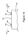
図2及び図3に示されるように、本明細書における第1の腰部パネル158a及び第2の腰部パネル158bは各々、第1の横方向縁部170及び第2の横方向縁部172を備え得、第2の横方向縁部172は、第1の横方向縁部170に対して長手方向内向きに位置決めされている。したがって、第1の横方向縁部170は、外側横方向縁部として構成されてもよく、第2の横方向縁部172は、内側横方向縁部として構成されてもよい。加えて、第1の腰部パネル158a及び第2の腰部パネル158bは、第1の横方向縁部170に隣接する第1の長手方向端部領域174と、第2の横方向縁部172に隣接する第2の長手方向端部領域176とを備え得、第1の長手方向端部領域174と第2の長手方向端部領域176は、中央領域178によって分離されている。第1の横方向縁部170及び第2の横方向縁部172は、第1の長手方向縁部180及び第2の長手方向縁部182と接続されても、またそれらによって分離されてもよい。したがって、第1の腰部パネル158a及び第2の腰部パネル158bはまた、第1の長手方向縁部180に隣接する第1の横方向端部領域184と、第2の長手方向縁部182に隣接する第2の横方向端部領域186とを含み得、第1の横方向端部領域184と第2の横方向端部領域186は、中央領域178によって分離されている。いくつかの構成では、第1の横方向縁部170、第2の横方向縁部172、第1の長手方向縁部180、及び/又は第2の長手方向縁部182は、折り目によって画定され得、腰部パネル158の1つ以上の層は、組み立て中にそれ自体又は別の層上に折り畳まれていてもよい。いくつかの構成では、第1の横方向縁部170、第2の横方向縁部172、第1の長手方向縁部180、及び/又は第2の長手方向縁部182は、折り畳まれていない縁部又は切断線によって画定され得、腰部パネル158の1つ以上の層は、組み立て中に切断又はトリミングされてもよい。
As shown in FIGS. 2 and 3, the first and
上で考察されたように、本明細書の腰部パネル158は弾性であり得、少なくとも1つの延伸方向を含み得る。いくつかの構成では、延伸方向は、第1の長手方向縁部180と第2の長手方向縁部182との間に横方向に配向され得る。いくつかの構成では、第1の腰部パネル158a及び/又は第2の腰部パネル158bは、0超~約3Nの加えられた力によって少なくとも約10mm伸展するように構成され得る。また、第1の腰部パネル158aは、第2の腰部パネル158bの延伸特性と同じかあるいは異なる延伸特性を備え得ることも理解されたい。そのような延伸特性は、収縮率又は伸長率を含み得る。いくつかの構成では、第1の腰部パネル158aの延伸特性は、第1の横方向縁部170と第2の横方向縁部172との間、及び/又は第1の長手方向縁部180と第2の長手方向縁部182との間で、同じであっても、異なっていてもよい。また、いくつかの構成では、第2の腰部パネル158bの延伸特性は、第1の横方向縁部170と第2の横方向縁部172との間、及び/又は第1の長手方向縁部180と第2の長手方向縁部182との間で、同じであっても、異なっていてもよい。
As discussed above, the
本明細書の腰部パネル158は、様々な形状及び/又はサイズで構成され得ることを理解されたい。例えば、図2及び図3に示されるように、第1の腰部パネル158aは、第1の長手方向縁部180と第2の長手方向縁部182との間に延在する第1の幅PW1を含み得、第2の腰部パネル158bは、第1の長手方向縁部180と第2の長手方向縁部182との間に延在する第2の幅PW2を含み得る。第1の幅PW1と第2の幅PW2は、等しくても、異なっていてもよいことを理解されたい。いくつかの構成では、第1の幅PW1及び/又は第2の幅PW2は、約80mm~約250mmであってもよく、具体的に言えば、上述の範囲及びその中に若しくはそれによって形成されるあらゆる範囲内の全ての1mmの増分が列挙される。第1の腰部パネル158aは、第1の横方向縁部170と第2の横方向縁部172との間に延在する第1の長さPL1を含み得、第2の腰部パネル158bは、第1の横方向縁部170と第2の横方向縁部172との間に延在する第2の長さPL2を含み得る。第1の長さPL1と第2の長さPL2は、等しくても、異なっていてもよいことを理解されたい。いくつかの構成では、第1の長さPL1及び/又は第2の長さPL2は、約5mm~約80mmであってもよく、具体的に言えば、上述の範囲及びその中に若しくはそれによって形成されるあらゆる範囲内の全ての1mmの増分が列挙される。
It should be understood that the
腰部パネル158は、様々な吸収性物品構成要素に対して様々な横方向位置及び長手方向位置に位置し得ることを理解されたい。いくつかの構成では、腰部パネル158は、腰部パネル158の第1の長手方向縁部180及び第2の長手方向縁部182が脚部ガスケット要素156の横方向内側に位置するように位置決めされ得る。いくつかの構成では、腰部パネル158は、第1の長手方向縁部180及び第2の長手方向縁部182、並びに腰部パネル158の第1の長手方向端部領域174及び第2の長手方向端部領域176が脚部ガスケット要素156と重なり合うように位置決めされ得る。いくつかの構成では、第1の腰部パネル158aは、吸収性物品100の第1の腰部縁部120から長手方向内側に、かつ/又は吸収性アセンブリ140の第1の横方向縁部148に向かって若しくはそれと重なり合うように位置付けられてもよく、第2の腰部パネル158bは、吸収性物品100の第2の腰部縁部122から長手方向内側に、かつ/又は吸収性アセンブリ140の第2の横方向縁部150に向かって若しくはそれと重なり合うように位置付けられてもよい。いくつかの構成では、第1の腰部パネル158a及び/又は第2の腰部パネル158bは、約1mm~約45mmにわたって吸収性アセンブリ140の第1の横方向縁部148及び/又は第2の横方向縁部150と重なり合ってもよく、具体的には、上述の範囲内及びその中に又はそれによって形成される全ての範囲内の全ての1mm刻みの増分が挙げられる。いくつかの構成では、第1の腰部パネル158aの第1の横方向縁部170は、ゼロよりも大きいオフセット距離OD1だけ、第1の腰部縁部120から長手方向内側に位置決めされ得る。いくつかの構成では、第2の腰部パネル158bの第1の横方向縁部170は、ゼロよりも大きいオフセット距離OD2だけ、第2の腰部縁部122から長手方向内側に位置決めされ得る。いくつかの構成では、オフセット距離OD1及び/又はオフセット距離OD2は、少なくとも5mmであってもよい。いくつかの構成では、第1の腰部パネル158aの第1の横方向縁部170は、オフセット距離OD1がゼロになるように、第1の腰部縁部120と境を接し得る。いくつかの構成では、第2の腰部パネル158bの第1の横方向縁部170は、オフセット距離OD2がゼロになるように、第2の腰部縁部122と境を接し得る。
It should be appreciated that the
第1の腰部パネル158a及び/又は第2の腰部パネル158bは、例えば、接着接合、超音波接合、圧力接合、熱接合、又はそれらの組み合わせなどによって、シャーシ102及び/又は脚部ガスケット要素156と様々な方式で接合され得ることを理解されたい。第1の腰部パネル158a及び/又は第2の腰部パネル158bは、例えば、スプレーノズル及び/又はスロットコーティングデバイスなど、様々な方式で適用された接着剤を用いて、シャーシ102及び/又は脚部ガスケット要素156と接合され得ることを理解されたい。いくつかの構成では、第1の腰部パネル158a及び/又は第2の腰部パネル158bは、接着剤によってシャーシ102及び/又は脚部ガスケット要素156と連続的に接合され得るか、あるいはパターン化された接着剤で連続的に接合され得る。いくつかの構成では、接着剤は、全て参照により本明細書に組み込まれる、米国特許第8,186,296号、同第9,265,672号、同第9,248,054号、及び同第9,295,590号、並びに米国特許出願公開第2014/0148773(A1)号に開示される装置及び/又は方法に従って適用され得る。いくつかの構成では、第1の腰部パネル158a及び/又は第2の腰部パネル158bは、例えば、全て参照によって本明細書に組み込まれる、米国特許第4,854,984号、同第6,248,195号、同第8,778,127号、同第9,005,392号、同第9,962,297号及び同第10,052,237号に開示された機械的接合デバイス及び方法など、様々な方式で圧力(また任意選択で熱)を加えることを伴って、シャーシ102及び/又は脚部ガスケット要素156に機械的に(圧力)接合され得る。いくつかの構成では、第1の腰部パネル158a及び/又は第2の腰部パネル158bは、例えば直線又は回転型の構成など、また例えば、米国特許第3,113,225号、同第3,562,041号、同第3,733,238号、同第5,110,403号、同第6,036,796号、同第6,508,641号、及び同第6,645,330号に開示されているものなど、様々な方法で構成された超音波接合方法を使用して、シャーシ102及び/又は脚部ガスケット要素156に機械的に(圧力)接合され得る。
It should be appreciated that the
前述のように、本明細書の腰部パネル158は、接着接合と圧力接合との組み合わせでシャーシ102及び/又は脚部ガスケット要素156と接合され得ることを理解されたい。例えば、図2Aに示されるように、第1の腰部パネル158aの第1の長手方向端部領域174は、シャーシ102及び/又は脚部ガスケット要素156と接着接合部188によって接合され得、これは、全体的に影付き領域によって示されている。加えて、第1の腰部パネル158aの第1の横方向端部領域184及び第2の横方向端部領域186は、圧力接合部190によってシャーシ102及び/又は脚部ガスケット要素156と接合され得る。いくつかの構成では、第1の腰部パネル158aの第1の横方向端部領域184及び第2の横方向端部領域186は、脚部ガスケット要素156の内側カフ及び/又は外側カフと接合され得る。図3Aに示されるように、第2の腰部パネル158bの第1の長手方向端部領域174は、シャーシ102及び/又は脚部ガスケット要素156と接着接合部188によって接着され得、これは、全体的に影付き領域によって示されている。加えて、第2の腰部パネル158bの第1の横方向端部領域184及び第2の横方向端部領域186は、圧力接合部190によってシャーシ102及び/又は脚部ガスケット要素156と接合され得る。いくつかの構成では、第2の腰部パネル158bの第1の横方向端部領域184及び第2の横方向端部領域186は、脚部ガスケット要素156の内側カフ及び/又は外側カフと接合され得る。いくつかの構成では、圧力接合部190は、別個の接合部位の不連続的なパターンであり得る。別個の接合部位は、様々なサイズ及び形状を画定し得、様々な距離だけ互いに分離され得ることを理解されたい。例えば、いくつかの構成では、別個の接合部位は、少なくとも0.2mmだけ互いに分離され得る。別個の接合部位は、腰部パネルの様々な異なるサイズのエリアを被覆し得ることも理解されたい。例えば、いくつかの構成では、複数の別個の接合部位は、腰部パネルのエリアの約5%~約50%を含み得る。いくつかの構成では、第1の長手方向縁部180及び第2の長手方向縁部182に沿って延在する、第1の横方向端部領域184及び第2の横方向端部領域186は、シールされた縁部を画定する連続的な接合部によって、シャーシ102及び/又は脚部ガスケット要素156と接合され得る。
As previously mentioned, it should be understood that the
いくつかの構成では、腰部パネル158の1つ以上の領域(本明細書では接合領域191と称される)は、シャーシ102及び/又は脚部ガスケット要素156と接合されてもよく、腰部パネル158の1つ以上の領域(非接合領域192と称される)は、シャーシ102及び/又は脚部ガスケット要素156と接合されなくても(取り付けられなくても)よく、それによって、腰部パネル158とシャーシ102との間にポケット194が形成される。例えば、図2Aに示されるように、第1の腰部パネル158aは、第1の腰部パネル158aの第1の長手方向端部領域174、第1の横方向端部領域184、及び第2の横方向端部領域186がシャーシ102及び/又は脚部ガスケット要素156と接合される接合領域191aを備え得、第1の腰部パネル158aは、第2の長手方向端部領域176の一部分及び第2の横方向縁部172の少なくとも一部分がシャーシ102及び/又は脚部ガスケット要素156に取り付けられなくてもよい少なくとも1つの非接合領域192a(破線の境界線を有する矩形によって全般的に示される)を含み得る。引き続き図3Aを参照すると、第2の腰部パネル158bは、第2の腰部パネル158bの第1の長手方向端部領域174、第1の横方向端部領域184、及び第2の横方向端部領域186がシャーシ102及び/又は脚部ガスケット要素156と接合される接合領域191bを備え得、第2の腰部パネル158bは、第2の長手方向端部領域176の一部分及び第2の横方向縁部172の少なくとも一部分がシャーシ102及び/又は脚部ガスケット要素156に取り付けられなくてもよい少なくとも1つの非接合領域192b(破線の境界線を有する矩形によって全般的に示される)を含み得る。
In some configurations, one or more areas of the waist panel 158 (referred to herein as bonded areas 191) may be bonded to the
本明細書の腰部パネル158は、様々な形状及び/又はサイズを有する1つ以上の非接合領域を伴って構成され得ることを理解されたい。例えば、図2A及び図3Aに示されるように、第1の腰部パネル158aは、第1の非接合領域192aを含み得、かつ/又は第2の腰部パネル158bは、第2の非接合領域192bを含み得る。したがって、第1の非接合領域192aは、横方向に延在する第1の幅UW1及び長手方向に延在する第1の長さUL1を含み得、第2の非接合領域192bは、横方向に延在する第2の幅UW2及び長手方向に延在する第2の長さUL2を含み得る。第1の幅UW1と第2の幅UW2は、等しくても、異なっていてもよいことを理解されたい。いくつかの構成では、第1の幅UW1及び/又は第2の幅UW2は、約40mm~約200mmであってもよく、具体的に言えば、上述の範囲及びその中に若しくはそれによって形成されるあらゆる範囲内の全ての1mmの増分が列挙される。また、第1の長さUL1と第2の長さUL2は、等しくても、異なっていてもよいことを理解されたい。いくつかの構成では、第1の長さUL1及び/又は第2の長さUL2は、約10mm~約50mmであってもよく、具体的に言えば、上述の範囲及びその中に若しくはそれによって形成されるあらゆる範囲内の全ての1mmの増分が列挙される。いくつかの構成では、第1の非接合領域192aは、第1のエリアA1を含み得、かつ/又は第2の非接合領域192bは、第2のエリアA2を含み得、第1のエリアA1と第2のエリアは、等しくても、異なっていてもよい。いくつかの構成では、第1のエリアA1及び/又は第2のエリアA2は、約400mm2~約10000mm2であってもよく、具体的に言えば、上述の範囲及びその中に若しくはそれによって形成されるあらゆる範囲内の全ての1mm2の増分が列挙される。
It should be understood that the
例えば、接着接合部188及び圧力接合部190を参照して上述した接合領域191は、恒久的接合として構成される。本明細書で使用するとき、「恒久的接合」とは、要素が通常の使用中に分離されることが意図されない様式で、2つ以上の要素又は要素の各部分を一緒に取り付けることを指す。そのような恒久的接合の分離は、取り付けだけでなく、要素の少なくとも一部の劣化をもたらす。
For example, bond region 191, described above with reference to
上述したように、腰部パネル158はまた、図2B及び図3Bに示されるように、脆弱接合部197を用いてシャーシ102と解放可能に接合されてもよい。恒久的な接合とは対照的に、「脆弱接合部」は、2つ以上の要素又は要素の各部分を一緒に取り付けることを指し、要素は、生産中に、通常の使用中に、あるいは接合の劣化により所定の期間後に分離され得る。しかし、分離すると、要素は、脆弱接合部で再取り付けすることができない。例えば、脆弱接合部は、脆弱接合部に接合された要素を含む物品の通常の使用中のある時点で消費者によって破壊されるように構成されてもよい。別の例では、脆弱接合部は、脆弱接合部で互いに接合された要素を含む物品の組み立て中のある時点で、物品の製造者によって損壊されるように構成されてもよい。更に別の例では、脆弱接合部は、ある期間にわたる接合強度の劣化の結果として損壊されるように構成されてもよい。いくつかの構成において、脆弱接合部は、使用中の物品の性能に影響を与えることを意図したものでなくてもよく、むしろ、脆弱接合部は、生産補助として使用されることを意図したものであってもよいことが理解されるべきである。したがって、上述の非接合領域192は、恒久的な接合によって、シャーシ102及び脚部ガスケット要素156などの吸収性物品100の他の要素と恒久的に接合されていない腰部パネル158の領域を指す。しかしながら、本明細書に記載される非接合領域192は、脆弱接合部197を用いて、シャーシ102及び脚部ガスケット要素156などの吸収性物品100の他の要素と解放可能に接合されてもよい。
As mentioned above, the
脆弱接合部197は腰部パネル158に対する様々な位置に配置されてよいことが理解されるべきである。例えば、図2Bに示すように、第1の腰部パネル158aは、第1の非接合領域192a内に位置決めされた第1の脆弱接合部197aを含んでもよい。したがって、第1の脆弱接合部197aは、第1の腰部パネル158aの第2の横方向縁部172と接合領域191aの各部分との間に長手方向に位置付けられてもよく、第1の腰部パネル158aの第1の長手方向端部領域174は、シャーシ102及び/又は脚部ガスケット要素156と恒久的に接合される。いくつかの構成では、第1の脆弱接合部197aは、第1の腰部パネル158aの第2の横方向縁部172上に位置付けられてもよい。第1の脆弱接合部197aはまた、接合領域191aの各部分の間で横方向に位置付けられてもよく、第1の腰部パネル158aの第1の横方向端部領域184及び第2の横方向端部領域186は、シャーシ102及び/又は脚部ガスケット要素156と恒久的に接合される。図3Bを参照すると、第2の腰部パネル158bは、第2の非接合領域192bに位置付けられた第2の脆弱接合部197bを含んでもよい。したがって、第2の脆弱接合部197bは、第2の腰部パネル158bの第2の横方向縁部172と接合領域191bの各部分との間に長手方向に位置付けられてもよく、第2の腰部パネル158bの第1の長手方向端部領域174は、シャーシ102及び/又は脚部ガスケット要素156と恒久的に接合される。いくつかの構成では、第2の脆弱接合部197bは、第2の腰部パネル158bの第2の横方向縁部172上に位置付けられてもよい。第2の脆弱接合部197bはまた、接合領域191bの各部分の間で横方向に位置付けられてもよく、第2の腰部パネル158bの第1の横方向端部領域184及び第2の横方向端部領域186は、シャーシ102及び/又は脚部ガスケット要素156と恒久的に接合される。
It should be appreciated that the weakened joint 197 may be located at various positions relative to the
本明細書の脆弱接合部197は、様々なサイズ、形状、及び量を有してもよく、腰部パネル158に対して様々な位置に配置されてもよいことを理解されたい。例えば、本明細書の脆弱接合部197は、1つ以上の実質的に直線状の線、s字形状、z字形状、c字形状、破線、T字形状、十字形状、螺旋形状、オメガ形状、円形形状、楕円形形状、長方形形状、正方形形状、様々な長さの5つ以上の辺を有する多角形形状、不規則形状、及びこれらの組み合わせを含む形状を画定してもよい。いくつかの構成では、脆弱接合部197は、基材内の機械的変形(エンボス加工など)によって画定される形状であってもよく、かつ/又は1つ以上の色の色差又は遷移を含んでもよく、図形(例えば、線)、記号又は文字)などによって構成される画像又はデザインを画定してもよい。いくつかの構成では、脆弱接合部197は、1次元(1-D)若しくは2次元(2-D)バーコード又はクイックレスポンス(QR)バーコードの形状であってもよい。いくつかの構成では、脆弱接合部197は、物品サイズ、物品前側、及び/又は物品後側の表示を提供する文字であってもよい。いくつかの構成では、脆弱接合部197は、特定のブランドロゴ又はアイコンに対応する形状であってもよい。
It should be understood that the weakened
図2C及び図3Cに示されるように、吸収性物品は、複数の第1の脆弱接合部197a及び/又は複数の第2の脆弱接合部197bを含んでもよい。加えて、第1の脆弱接合部197aは、同じ又は異なるサイズ及び/又は形状を有してもよく、第2の脆弱接合部197bは、同じ又は異なるサイズ及び/又は形状を有してもよい。加えて、第1の脆弱接合部197aは、第2の脆弱接合部197bと同じ又は異なるサイズ、形状、及び/又は量を有してもよい。また、本明細書の脆弱接合部197は、腰部パネル158をシャーシ及び/又は脚部ガスケット要素に解放可能に接合するように構成されてもよいことも理解されたい。
As shown in Figures 2C and 3C, the absorbent article may include a plurality of first weakened
脆弱接合部197は、接着接合部及び/又は機械的接合部として構成され得ることが理解されよう。例えば、脆弱接合部は、超音波接合及び上述した他のものなどの様々な方式で圧力(及び任意選択的に熱)の印加を利用し得る様々な方法で生成される機械的接合部であってもよい。いくつかの構成では、脆弱接合部は、静電荷を用いて生成されてもよい。いくつかの構成では、脆弱接合部は、不織布などの少なくとも2つの基材からの繊維の絡み合いを含んでもよい。いくつかの構成では、脆弱接合部197は、参照により本明細書に組み込まれる米国特許第9,610,202号に開示されているような、ある期間後に崩壊して機能しなくなる接着接合部として構成されてもよい。例えば、脆弱接合部197は、ある期間後に第1の接合強度よりも低い第2の接合強度に減衰する第1の接合強度を備えてもよい。このような脆弱接合部は、吸収性物品がパッケージ内に収容されている間に崩壊及び損壊するように構成されてもよい。いくつかの構成では、脆弱接合部197は、第1の接合強度を備えてもよく、この第1の接合強度は、使用者が着用している吸収性物品内に生じ得る湿気及び/又は熱に曝された結果として、第1の接合強度よりも低い第2の接合強度に減衰する。別の例では、恒久的接合領域191は、第1の接着剤を用いて作製されてもよく、脆弱接合部197は、第2の接着剤を用いて作製されてもよく、第1の接着剤と第2の接着剤は、互いに同一であっても異なっていてもよい。いくつかの構成では、第1の接着剤は第1の坪量を含んでもよく、第2の接着剤は第2の坪量を含んでもよく、第1の坪量は第2の坪量よりも大きい。いくつかの構成では、脆弱接合部197は、例えば、全て参照により本明細書に組み込まれる、米国特許第5,607,760号、同第5,609,587号、同第5,635,191号、同第5,643,588号、及び同第6,498,284号、並びに国際公開第2020/247980(A1)号に記載されているローションなどのローションを吸収性物品の1つ以上の構成要素に塗布することによって形成されてもよい。いくつかの構成では、脆弱接合部197は、参照により本明細書に組み込まれる米国特許第8,702,900号に開示されているようなホットメルト接着剤で形成されてもよい。吸収性物品100は、様々な方式で本明細書に記載される、腰部パネル158を含む様々な構成要素と共に組み立てられ得ることを理解されたい。したがって、以前の考察の文脈において、様々な装置及び方法は、第1の腰部パネル158a及び/又は第2の腰部パネル158bに脆弱接合部197を備えた第1の腰部パネル158a及び第2の腰部パネル158bを吸収性物品100に組み付けるように適合され得る。例えば、図4は、吸収性物品100の組み立て中に積層体204を形成するために、張力下で、別個の弾性部200を前進するキャリア基材202と接合する装置又はシステム300を含む変換プロセスの概略図を示す。図4に示される装置300及び関連するアセンブリの様々な態様は、米国特許出願第16/864,267号、同第16/864292号、同第17/029,211号、及び同第17/029,486号に開示されており、これらは全て参照により本明細書に組み込まれる。
It will be appreciated that the weak joint 197 may be configured as an adhesive joint and/or a mechanical joint. For example, the weak joint may be a mechanical joint created in various ways, which may utilize the application of pressure (and optionally heat) in various manners, such as ultrasonic bonding and others described above. In some configurations, the weak joint may be created using electrostatic charges. In some configurations, the weak joint may include the intertwining of fibers from at least two substrates, such as nonwoven fabrics. In some configurations, the weak joint 197 may be configured as an adhesive joint that collapses and fails after a period of time, such as disclosed in U.S. Pat. No. 9,610,202, which is incorporated herein by reference. For example, the weak joint 197 may comprise a first bond strength that decays to a second bond strength lower than the first bond strength after a period of time. Such a weak joint may be configured to collapse and break while the absorbent article is contained within the package. In some configurations, the weakened
図4及び図5に示されるように、キャリア基材202は、第1の速度S1で機械方向MDに前進し得る。キャリア基材は、第1の長手方向縁部206と、幅WCSを画定するように第1の長手方向縁部206から横断方向CDに分離された第2の長手方向縁部208とを備える。キャリア基材202はまた、第1の表面210と、対向する第2の表面212とを含む。以下でより詳細に考察されるように、別個の弾性部200は、キャリア基材202の第1の表面210と接合される。
4 and 5, the
上で考察された吸収性物品100の構成要素及びその組み立てプロセスの文脈において、弾性部200は、腰部パネル158として構成され得る。いくつかの構成では、各別個の弾性部200は、第1の腰部パネル158a、第2の腰部パネル158bとして構成されてもよく、あるいは、第1の腰部パネル158a及び第2の腰部パネル158bへと形成されるように後にキャリア基材202と共に切断される部分であってもよい。キャリア基材202は、連続的なトップシート138、バックシート136、又は連続的な長さのシャーシ102の一部分でもあり得る組み合わされたトップシート138とバックシート136の連続的な積層体として構成され得る。積層体204は、連続的な長さの吸収性物品100として構成され得る。いくつかの構成では、キャリア基材202の第1の表面210は、トップシート138又はバックシート136の着用者対向表面132又は衣類対向表面134に対応し得る。いくつかの構成では、弾性部200は、トップシート138とバックシート136との間に接合され得る。例えば、弾性部200は、後にトップシート138と接合されるバックシート136の着用者対向表面132と接合され得る。別の例では、弾性部200は、後にバックシート136と接合されるトップシート138の衣類対向表面134と接合され得る。更に別の例では、弾性部200は、バックシート136の衣類対向表面134と接合され得、バックシート136の着用者対向表面132は、トップシート138と事前に接合されていてもよく、あるいは後にトップシート138と接合されてもよい。別の例では、弾性部200は、トップシート136の着用者対向表面132と接合され得、トップシート138の衣類対向表面134は、バックシート136と事前に接合されていてもよく、あるいは後にバックシート136と接合されてもよい。図17及び図18を参照して上で考察されたように、腰部パネル158及びシャーシ102は、様々な材料の組み合わせ及び構成を含んでもよく、したがって、そのような組み合わせはまた、弾性基材200a、弾性部200、及びキャリア基材202にも適用可能であることを理解されたい。
In the context of the components of the
図5Aに示されるように、キャリア基材202はまた、第1の長手方向縁部206及び第2の長手方向縁部208に隣接して第1の表面210上に位置決めされた脚部ガスケット要素156を含み得る。したがって、別個の弾性部200の各部分もまた、脚部ガスケット要素156と接合され得る。いくつかの構成では、別個の弾性部200は、キャリア基材202と接合され得、脚部ガスケット要素156は、その後にキャリア基材202と接合され得る。脚部ガスケット要素156は、脚部ガスケット要素156が弾性部200の対向する端部部分を部分的に覆う又はそれと重複することができるように、あるいは覆う又は重複することができないように、弾性部200に対して位置決めされ得る。いくつかの構成では、脚部ガスケット要素156は、弾性部200とキャリア基材202との間に挟まれ得る。また、いくつかの構成では、弾性部200は、脚部ガスケット要素156とキャリア基材202との間に挟まれ得る。
5A, the
ここで図4及び図6を参照すると、連続的な弾性基材200aが、機械方向MDに第2の速度S2で前進されており、第2の速度S2は、第1の速度S1よりも遅い。連続的な弾性基材200aは、第1の長手方向縁部214と、幅WESを画定するように第1の長手方向縁部214から横断方向CDに分離された第2の長手方向縁216とを備える。連続的な弾性基材200aはまた、第1の表面218と、対向する第2の表面220とを含む。連続的な弾性基材200aは、少なくとも1つの方向に延伸可能であり、連続的な弾性基材200aが横断方向CDに延伸可能となるように方向付けられる。したがって、連続的な弾性基材の幅WESは、非延伸時の幅であり得る。いくつかの構成では、連続的な弾性基材200aの幅WESは、部分的延伸時の幅であり得る。
4 and 6, the continuous
図4、図6、及び図7を引き続き参照すると、システム300は、接着剤222を連続的な弾性基材200aの第2の表面220上に堆積させる接着剤アプリケータデバイス302を含み得る。この接着剤アプリケータデバイス302は、例えば、スプレーノズル及び/又はスロットコーティングデバイスなどの様々な方式で構成され得ることを理解されたい。いくつかの構成では、接着剤アプリケータデバイス302は、全て参照によって本明細書に組み込まれる、米国特許第8,186,296号、同第9,265,672号、同第9,248,054号、及び同第9,295,590号、並びに米国特許出願公開第2014/0148773(A1)号に開示される装置及び/又は方法に従って構成され得る。
4, 6, and 7, the
接着剤222は、連続的な弾性基材200aに対して様々な形状及びサイズを有する接着剤222の領域を第2の表面220上に画定するように、連続的な弾性基材200aに適用され得ることを理解されたい。例えば、図7に示されるように、接着剤222は、機械方向MD及び横断方向CDに連続的に延在する接着剤222の領域224を画定するように、連続的な弾性基材200aの第2の表面220に適用され得る。接着剤222は、幅WADHを画定するように横断方向CDに延在し得る。いくつかの構成では、接着剤222の幅WADHは、連続的な弾性基材200aの幅WESよりも短くてもよく、またいくつかの構成では、幅WADHは、連続的な弾性基材200aの幅WESに等しくてもよい。
It should be appreciated that the adhesive 222 may be applied to the continuous
図4、図7、及び図8に示されるように、連続的な弾性基材200aは、接着剤アプリケータデバイス302から、連続的な弾性基材200aから別個の弾性部200を切断及び分離する切断デバイス304へと、機械方向MDに前進し得る。したがって、別個の弾性部200は各々、前縁部230及び後縁部232を含み、前縁部230から後縁部232へと機械方向MDに延在する長さLEPを画定する。弾性部200はまた、前縁部230と後縁部232との間に延在する連続的な弾性基材200aの長手方向縁部214、216に対応する第1の長手方向縁部214及び第2の長手方向縁部216を含む。加えて、弾性部200は、連続的な弾性基材200aの第1の表面218及び第2の表面220に対応する第1の表面218及び第2の表面220を含む。
As shown in Figures 4, 7 and 8, the continuous
図8に示されるように、別個の弾性部200はまた、第1の長手方向縁部214に隣接する第1の端部領域234と、第2の長手方向縁部216に隣接する第2の端部領域236とを含み、第2の端部領域236は、中央領域238によって横断方向CDにおいて第1の端部領域234から分離されている。上で考察されたように、連続的な弾性基材200aの第2の表面220に接着剤222が適用され得る。したがって、別個の弾性部200は、第2の表面220上に接着剤222のゾーン240を含み得る。接着剤222のゾーン240は、弾性部200に対して様々なサイズ及び形状を画定し得ることを理解されたい。例えば、図8に示されるように、接着剤のゾーン240は、別個の弾性部200の全幅W1未満にわたって横断方向CDに延在してもよい。いくつかの構成では、接着剤222のゾーン240は、別個の弾性部200の第2の表面220の第1の端部領域234及び第2の端部領域236がいかなる接着剤222も含まなくてもよいように、別個の弾性部200の中央領域238上にのみ位置決めされてもよい。
As shown in FIG. 8, the separate
図4及び図9に示されるように、切断デバイス304は、それらの間にニップ310を画定するようにアンビルロール308に隣接して位置決めされたナイフロール306を含み得る。ナイフロール306は、外周表面312と、軸316を中心として第1の方向Dir1に回転するように適合された1つ以上のブレード314とを含み得る。アンビルロール308は、軸320を中心として、第1の方向Dir1の反対側の第2の方向Dir2に回転するように適合された外周表面318を含み得、そのため、外周表面318は、第3の速度S3で前進し、第3の速度S3は、第2の速度S2よりも高速である。引き続き図4を参照すると、連続的な弾性基材200aがナイフロール306とアンビルロール310との間のニップ310を通って前進するとき、ブレード314は、連続的な弾性基材200aから別個の弾性部200を切断するように動作する。アンビルロール308の外周表面318は第3の速度S3で前進するため、切断された別個の弾性部200は、次いで、アンビルロール308の外周表面318上で第2の速度S2から第3の速度S3へと加速し得る。また、切断デバイス304の1つ以上の構成要素は、一定及び/又は可変速度で動作するように構成され得ることも理解されたい。例えば、ナイフロール306及び/又はアンビルロール308は、例えば、ナイフロール306及び/又はアンビルロール308を一定及び/又は可変の角速度で回転させ得る、サーボモータなどの様々なタイプのモータと接続され得る。
As shown in Figures 4 and 9, the
いくつかの構成では、第3の速度S3は、前進するキャリア基材202の第1の速度S1に等しくてもよい。いくつかの構成では、第3の速度S3は、前進するキャリア基材202の第1の速度S1未満であっても、あるいはそれを超えていてもよく、したがって、別個の弾性部は、キャリア基材202と組み合わされる前に、第3の速度S3から第1の速度S1へと、アンビルロール308の下流で加速又は減速されてもよい。キャリア基材の第1の速度S1は第2の速度S2よりも速いため、別個の弾性部200は、キャリア基材202と接合する前に第2の速度S2から第1の速度S1へと加速される。別個の弾性部200を第2の速度S2から第1の速度S1へと加速することによって、連続的に切断された別個の弾性部200の後縁部232(又は前縁部230)は、図1A及び図1Bを参照して上述されたピッチ長PLに対応し得る、図14に示されるようなピッチ距離PDだけ機械方向MDに互いに分離され得る。アンビルロール308はまた、アンビルロール308が回転するときに、別個の弾性部200を外周表面318上に保持するのを助けるために、別個の弾性部200に真空圧力を加えるように構成され得る。
In some configurations, the third speed S3 may be equal to the first speed S1 of the advancing
切断デバイス304は様々な形態で構成され得ることを理解されたい。例えば、いくつかの構成では、ブレード314は、結果として生じる切断線及び別個の弾性部200の対応する前縁部230及び後縁部232が直線状及び/又は湾曲状となり得るように構成され得る。また、切断デバイス304は、前縁部230及び後縁部232に隣接する切断線に沿った材料が互いに融合及び/又は圧力接合されるように別個の弾性部200を切断するように適合され得る。ナイフロール306及びアンビルロール308の位置は、図4に示されるものとは反対であってもよく、したがって、別個の弾性部200は、アンビルロール308とは対照的に、ナイフロール306の外周表面312上に留まり得ることも理解されたい。切断デバイス304は、異なる方式で別個の弾性部200を移送及び/又は切断するように構成され得ることも理解されたい。
It should be understood that the
図4を参照すると、装置300は、別個の弾性部200を切断デバイス304から接合デバイス324に移送する回転可能な移送デバイス322を含み得、接合デバイス324は次に、弾性部200をキャリア基材202と組み合わせる。移送デバイス322はまた、別個の弾性部200を横断方向CDに延伸するように構成され得る。したがって、移送デバイス322は、図9及び図10に示されるようなスプレッダ機構326として構成され得る。図4、図9、及び図10を引き続き参照すると、移送デバイス322は、それらの間にニップ328を画定するように、アンビルロール308に隣接して位置決めされ得る。以下でより詳細に考察されるように、別個の弾性部200は、アンビルロール308から受容され、スプレッダ機構326は、別個の弾性部200を横断方向CDに延伸するように動作する。次いで、延伸された別個の弾性部200は、スプレッダ機構326から接合デバイス324の回転構成要素上に前進され、次いで、延伸された別個の弾性部200がキャリア基材202上に接合される。
4, the
図9及び図10に示されるように、スプレッダ機構326は、第1のディスク330及び第2のディスク332を含み得、第1のディスク330は、第2のディスク332から横断方向CDに変位される。第1のディスク330は、回転軸330aを中心に回転するように適合され、第2のディスク332は、回転軸332aを中心に回転するように適合され、第1のディスク330及び第2のディスク332は、第2の方向Dir2の反対側の第3の方向Dir3に回転し得る。図11に示されるように、第1のディスク330は、内部縁330cと外縁部330dとの間で軸方向に延在する外側リム330bを含み、第2のディスク332は、内部縁332cと外縁部332dとの間で軸方向に延在する外側リム332bを含む。
9 and 10, the
図9~図11に示されるように、第1のディスク330及び第2のディスク332は、外側リム330b、332bが、第1の場所における最小距離Dminから第2の場所における最大距離Dmaxまで増加する距離Dだけ互いに分離されるように、互いに対して傾斜している。以下で考察されるように、別個の弾性部200は、動作中に切断デバイス304から外側リム330b、332b上に移送される。第1のディスク330及び第2のディスク332が傾斜しているため、ディスク330、332の回転により、リム330b、332bが別個の弾性部200の第1の端部領域234及び第2の端部領域236を引っ張り、別個の弾性部200が接合デバイス324に移送される前に、別個の弾性部200の中央領域238を横断方向CDに延伸させる。図4、図8、及び図12に示されるように、スプレッダ機構326は、第1の幅W1から、第1の幅W1よりも大きい第2の幅W2まで、別個の弾性部200を横断方向に延伸するように動作し得る。
9-11, the
図4、図9、及び図10を参照すると、ディスク330、332はまた、動作中に別個の弾性部200の対向する第1の端部領域234及び第2の端部領域236を把持するのを助けるように構成され得る。例えば、第1のディスク330及び第2のディスク332は各々、真空圧力源334と流体接続され得る。したがって、動作中に別個の弾性部200をリム330b、332b上に保持するのを助けるために、真空圧が使用され得る。図11及び図11Aに示されるように、ディスク330、332はまた、リム330b、332bから半径方向外向きに突出するナブ336を含み得る。したがって、ナブ336はまた、別個の弾性部200の中央領域238を延伸させている間に、別個の弾性部200の第1の端部領域234及び第2の端部領域236がリム330b、332bに沿って摺動するのを防止するのに役立ち得る。別個の弾性部200の第1の端部領域234及び第2の端部領域236は延伸動作中にリム330b、332b上に保持されるので、別個の弾性部200の中央領域238は延伸されるが、第1の端部領域234及び第2の端部領域236は延伸されない場合があり、あるいは中央領域238よりもはるかに小さい程度にしか延伸されない場合があることにも留意されたい。
4, 9, and 10, the
図8を参照して前で考察されたように、弾性部200は、別個の弾性部200の中央領域238上に位置決めされた接着剤222のゾーン240を含んでもよく、別個の弾性部200の第2の表面220の第1の端部領域234及び第2の端部領域236の一部又は全ては接着剤222をまったく含まなくてもよい。図4、図9、及び図10に示されるように、移送デバイス322に移送されると、弾性部200は、第1の表面218が半径方向外向きに面し得、第2の表面220及び接着剤222のゾーン240が半径方向内向きに面し得るように向けられてもよい。したがって、スプレッダ機構326のディスク330、322の構成配置は、接着剤222をディスク330、332と接触させる必要なく、半径方向内向きに面する接着剤222のゾーン240を用いて、弾性部200を切断デバイス304から接合デバイス324へと回転可能に搬送する能力を提供する。
As previously discussed with reference to FIG. 8, the
上で考察されたように、切断された別個の弾性部200は、アンビルロール308の外周表面318上で第2の速度S2から第3の速度S3へと加速し、いくつかの構成では、第3の速度S3は、前進するキャリア基材202の第1の速度S1よりも遅くても、あるいは速くてもよい。したがって、移送デバイス322は、別個の弾性部200を第1の速度S1へと加速又は減速するために、可変角速度で回転するように構成され得る。例えば、第3の速度S3が第1の速度S1よりも遅い場合、移送デバイス322は、第1のディスク330のリム330b及び第2のディスク332のリム332bが第3の速度S3でニップ328を通って移動する間に、アンビルロール308から別個の弾性部200を受容するように構成され得る。次いで、ディスク330、332の角速度は、別個の弾性部200を接合デバイス324に移送する前に、別個の弾性部200を第1の速度S1へと加速させるように変更され得る。別の例では、第3の速度S3が第1の速度S1よりも速い場合、ディスク330、332の角速度は、別個の弾性部200を接合デバイス324に移送する前に、別個の弾性部200を第1の速度S1へと減速させるように変更され得る。第3の速度S3が第1の速度S1に等しい状況では、ディスク330、332は、一定の角速度で回転し得る。スプレッダ機構326は、例えば、参照により本明細書に組み込まれる欧州特許公開第EP2260813(B1)号に開示されているような可変角速度で回転する必要性に対処するために様々な方法で構成され得ることを理解されたい。可変角速度で移送デバイス326において回転する能力は、より小さいサイズ又はより大きいサイズの吸収性物品100を組み立てるときに装置300の構成要素を交換する必要性を低減するのに役立ち得るが、これは、連続的に切断された別個の弾性部200間のピッチ距離の低減又は増加を必要とし得る。
As discussed above, the cut separate
前述のように、回転可能な移送デバイス322は、別個の弾性部200を切断デバイス304から接合デバイス324に移送するように構成され得る。図4、図9、及び図10に示されるように、接合デバイス324は、それらの間にニップ338を画定するように、スプレッダデバイス326の第1のディスク330及び第2のディスク332に隣接して位置決めされ得る。いくつかの構成では、第1のディスク330及び第2のディスク332は、接合デバイス324への移送中にディスク330、332から別個の弾性部200を取り外すのを助けるために、ブローオフ空気と称されることもある正の空気圧をニップ338に隣接する別個の弾性部200に適用するように構成され得る。以下でより詳細に考察されるように、別個の弾性部200は、中央領域238が横断方向CDに延伸された状態でスプレッダ機構326から受容され、接合デバイス324は、別個の弾性部200を延伸状態で、前進するキャリア基材202に移送し接合する。
As previously described, the
接合デバイス324が様々な方式で構成され得ることを理解されたい。例えば、図4、図9、及び図10に示されるように、接合デバイス324は、パターンロール340及びパターンロール340に隣接する押圧表面342によってそれらの間にニップ344を画定するように構成され得る。パターンロール340は、外周表面346を含み、回転軸348を中心に回転し、パターンロール340は、第3の方向Dir3の反対側の第4の方向Dir4に回転し得る。加えて、パターンロール340は、外周表面346が第1の速度S1で、あるいはおおよそ第1の速度S1で前進するように回転し得る。動作中、延伸状態にある別個の弾性部200は、第1のディスク330及び第2のディスク332からパターンロール340の外周表面346に移送される。パターンロール340は、パターンロールの外周表面346と前進するキャリア基材202との間で、延伸した弾性部200を前進させるように回転する。具体的には、別個の弾性部200の第1の表面218は、パターンロール340の外周表面346と向かい合う関係をなして、またそれと直接接触して位置決めされ得る。したがって、接着剤222のゾーン240及び別個の弾性部200の第2の表面は、回転軸348から半径方向外向きに面していてもよい。キャリア基材202は、キャリア基材200の第1の表面210がパターンロール340の外周表面346と直接接触し、またそれと対向関係をなすように、パターンロール340へと前進する。パターンロール340が回転すると、別個の弾性部200の第2の表面220は、キャリア基材200の第1の表面210と直接接触し、それと対向関係をなして位置決めされる。組み合わされた別個の弾性部200とキャリア基材202は、パターンロール340と押圧表面342との間のニップ344を通って前進して、別個の弾性部200とキャリア基材202とを一緒に機械的に接合する。
It should be understood that the
図4に示されるように、接合デバイス324は、アンビルロール350を含む機械的接合デバイスとして構成され得る。アンビルロール350は、外周表面352を含み、回転軸354を中心に回転し、アンビルロール350は、第4の方向Dir4の反対側の第5の方向Dir5に回転し得る。アンビルロール350の外周表面352は、パターンロール340と共に動作する押圧表面342を画定し得る。図13及び図13Aに示されるように、パターンロール340の外周表面346はまた、半径方向外向きに延在する接合要素358によって画定された1つ以上の接合表面356を備え得る。パターンロール340が回転すると、別個の弾性部200及びキャリア基材200は、接合表面356と押圧表面342との間で前進されて、弾性部200及びキャリア基材202を一緒に機械的に接合又は溶接して、弾性部200とキャリア基材202との間に接合部242を作り出す。押圧表面342とパターンロール340との間の熱及び/又は圧力は、パターンロール340上の接合表面356によって支持されるエリアにおいて、キャリア基材202と弾性部200を一緒に溶融及び接合し得る。図14に示されるように、機械的接合部及び/又は接合領域242は、接合表面356の形状に対応し、接合表面356の形状を反映し得る形状を有してもよい。
As shown in FIG. 4, the
したがって、積層体204がニップ344を通って前進するとき、キャリア基材202と別個の弾性部200は、一緒に機械的に接合又は溶接される。本明細書における接合デバイス324は、別個の弾性部200をキャリア基材202と接合するための、本明細書に記載の様々な特徴を伴って、様々な方式で構成され得ることを理解されたい。したがって、パターンロール340及び/又はアンビルロール350は、例えば、米国特許第4,854,984号、同第6,248,195号、同第8,778,127号、同第9,005,392号、同第9,962,297号、及び同第10,052,237号に記載されている機械的接合デバイス及び方法などのように、機械的接合を実施するために様々な方法で熱及び圧力を加えるように構成され得る。また、パターンロール340及びアンビルロール350の位置は、図4に示されたものとは反対であってもよく、したがって、別個の弾性部200は、パターンロール340とは対照的に、移送デバイス322からアンビルロール350の外周表面352に移送され得ることも理解されたい。また、接合デバイス324の1つ以上の構成要素は、一定及び/又は可変速度で動作するように構成され得ることも理解されたい。例えば、パターンロール340及び/又はアンビルロール350は、例えば、パターンロール340及び/又はアンビルロール350を一定及び/又は可変の角速度で回転させ得るサーボモータなどの様々なタイプのモータと接続され得る。
Thus, as the laminate 204 advances through the
いくつかの構成では、キャリア基材202は、パターンロール340の外周表面346の周りに部分的に巻き付けられ得る。したがって、接合デバイス324は、キャリア基材202をパターンロール340にかつ/又はパターンロール340から誘導するのに役立つ1つ以上のロールを含み得る。例えば、図4に示されるように、接合デバイスは、弾性部202が移送デバイス322から受容されるニップ338の下流で、かつパターンロール340と押圧表面342との間にあるニップ344の上流で、キャリア基材202をパターンロール340の外周表面346上へと誘導するのに役立つガイドロール360を含んでもよい。ガイドロール360はまた、接着ゾーン240の接着剤222とキャリア基材202との接合を増強するのを助けるために、キャリア基材202及び弾性部200に対して圧力を加えるように構成され得る。
In some configurations, the
接合デバイス324は、加熱された若しくは加熱されていないパターンロール、アンビルロール及び/又は超音波接合デバイスなどの様々な方式で構成されてもよいことを理解されたい。例えば、図4Aに概略的に示される接合デバイス324は、パターンロール340と、超音波接合デバイス364のエネルギー伝達表面362を含む押圧表面342とを含み得る。したがって、接合デバイス364は、ホーン366を含んでもよく、パターンロール340上の組み合わされた弾性部200とキャリア基材202に超音波エネルギーを付与するように構成されてもよい。
It should be understood that the
超音波接合デバイス364の態様は、例えば、直線又は回転型の構成など、また例えば、米国特許第3,113,225号、同第3,562,041号、同第3,733,238号、同第5,110,403号、同第6,036,796号、同第6,508,641号、及び同第6,645,330号に開示されているものなど、様々な形態で構成され得ることを理解されたい。いくつかの構成では、超音波接合デバイス364は、例えば、Herrmann Ultrasonic,Inc.から入手可能な、線形振動型ソノトロードとして構成されてもよい。いくつかの構成では、ソノトロードは、横断方向CDに一緒に入れ子にされた複数のソノトロードを含んでもよい。回転ホーンはまた、一定及び/又は可変角速度で回転するように構成され得ることも理解されたい。
It should be appreciated that aspects of the
上で考察されたように、パターンロール340は、接合表面356を画定するように半径方向外向きに延在する接合要素358を含む。次に、別個の弾性部200とキャリア基材202との間の接合部及び/又は接合領域242は、接合表面356に対応し、接合表面356の形状を反映し得る形状を有し得る。パターンロール340は、様々な量及び/又は形状の接合表面356を有し得、かかる接合表面356は、パターンロール340上の様々な場所に位置決めされ得ることを理解されたい。例えば、図13、図13A、図14、及び図15に示されるように、接合要素358及び接合表面356は、別個の弾性部200の第1の端部領域234及び第2の端部領域236に対応するように位置決めされ得る。したがって、接合デバイス340は、延伸した中央領域238を機械的に接合することなく、弾性部200の第1の端部領域234及び第2の端部領域236を機械的に接合するように動作し得る。いくつかの構成では、接合要素358及び接合表面356は、別個の弾性部200の中央領域238とキャリア基材202とを一緒に接合するために、機械的接合部242も適用されるように位置決めされ得る。
As discussed above, the
パターンロール340はまた、パターンロール340が回転するときに、別個の弾性部200を外周表面346上に保持するのを助けるために、別個の弾性部200に真空圧力を加えるように構成され得る。真空圧力はまた、パターンロール340上に位置決めされている間に、別個の弾性部200を延伸状態に保持するのに役立ち得る。加えて、接合要素358及び接合表面356はまた、弾性部200を把持するのに役立ち、弾性部200を延伸状態に保持するのに役立ち得る。加えて、パターンロール340はまた、接合要素358の接合表面356を通して真空圧力を加えるように構成され得る。更に、パターンロール340は、スプレッダ機構326の第1のディスク330及び第2のディスク332とインターフェース接続して、ニップ338におけるパターンロール340への移送中に別個の弾性部200の延伸状態を維持するのを助けるように構成され得る。例えば、上で考察されたように、スプレッダ機構326のディスク330、332は、リム330b、332bから半径方向外向きに突出する様々な量のナブ336を含み得、ナブ336は、弾性部200の第1の端部領域234及び第2の端部領域236が、別個の弾性部200を延伸させる間にリム330b、332bに沿って互いに向かって摺動するのを防止するのに役立ち得る。ナブ336は、様々な形状及びサイズ、間隔で構成され得、様々なタイプの材料から構成され得ることを理解されたい。いくつかの構成では、パターンロール340上の接合要素358は、第1のディスク330のリム330b及び第2のディスク332のリム332bから突出するナブ336と噛み合うように構成され得る。ナブ336と接合要素358との間の噛み合いは、装置300が、移送デバイス322から接合デバイス324に移送するときに、別個の弾性部200の延伸状態を維持するのに役立ち得る。
The
図4に示されるように、別個の弾性部200がキャリア基材202と接合されて積層体204を作り出した後、積層体204は、接合デバイス324から機械方向MDに前進し続けることができ、また切断、折り畳み、及び/又は包装作業などの追加の変換作業に供され得る。いくつかの構成では、積層体204は、連続的な長さの吸収性物品を画定してもよく、あるいは、連続的な長さの吸収性物品を画定するように追加の基材及び/又は構成要素と組み合わされてもよい。次に、連続的な長さの吸収性物品は、別個の吸収性物品を連続的な長さの吸収性物品から分離する最終ナイフ切断に供され得る。前述のように、別個の弾性部200は、吸収性物品100上の腰部パネル158に対応し得、キャリア基材202は、トップシート基材138又はバックシート基材136に対応し得る。いくつかの構成では、本明細書の装置及び方法は、別個の弾性部200を別個の前側及び/又は後側腰部パネル158として適用するように構成され得る。いくつかの構成では、別個の弾性部200は、キャリア基材202に適用され得、その後に別個の弾性部200は、図14~図14Cを参照して以下に更に議論されるように、最終的なナイフ切断動作中に、前側腰部領域116内に位置付けられる前側腰部パネル158a及び後側腰部領域118内に位置付けられる後側腰部パネル158bへと切断される。そのような最終的なナイフ切断動作は、キャリア基材202及び別個の弾性部200を通る直線状及び/又は曲線状の切断線を適用するように構成され得ることを理解されたい。キャリア基材202は、例えば、接合デバイス324の上流でキャリア基材202に取り付けられた横方向に延在する側部パネルなどの部分を含み得ることも理解されたい。したがって、システム300はまた、キャリア基材202、特にそのような横方向に延在する特徴部を接合デバイス324内に誘導し、制御することを助けて、そのような特徴部の意図しない接合を防止するのを助けるための、レール及び/又はコンベヤなどのデバイスを含むことができる。
As shown in FIG. 4, after the
上で考察されたように、別個の弾性部は、キャリア基材接着剤及び/又は機械的接合部と組み合わされ得る。接着剤及び機械的接合部が様々な方式で構成され得ることを理解されたい。接着剤222のゾーン240は、別個の弾性部200及び/又はキャリア基材202に対して様々な異なる形状及びサイズを画定するように適用され得ることも理解されたい。例えば、図14に示されるように、接着剤222のゾーン240は、機械方向MDにおける長さLAZを画定し得る。いくつかの構成では、接着剤222のゾーン240の長さLAZは、別個の弾性部200の全長LEP未満にわたって延在し得る。いくつかの構成では、接着剤222のゾーン240は、横方向CDに延在して、弾性部200の前縁部230及び後縁部232のうちの1つ又は両方と境を接し得る。いくつかの構成では、接着剤222のゾーン240の長さLAZは、前縁部230から後縁部232へと延在する別個の弾性部200の全長LEPにわたって延在し得る。
As discussed above, the separate elastics may be combined with carrier substrate adhesives and/or mechanical joints. It should be understood that the adhesives and mechanical joints may be configured in a variety of ways. It should also be understood that the
図4を参照して上で考察されたように、システム300は、ナイフロール306とアンビルロール308との間のニップ310の上流の連続的な弾性基材200aに接着剤222を適用するように構成され得る接着剤アプリケータデバイス302を含み得る。次に、連続的な弾性基材200aから分離された別個の弾性部200は、弾性部200をキャリア基材202と接着接合するように適合された接着剤222のゾーン240を含み得る。接着剤222のゾーン240は、組み立てプロセスにおいて様々な構成及び/又は位置で、連続的な弾性基材200a、弾性部200、及び/又はキャリア基材202に適用される接着剤222を含み得ることを理解されたい。例えば、図4に示されるように、システム300は、ナイフロール306とアンビルロール308との間のニップ310の下流の位置において別個の弾性部200に接着剤222を適用するように構成され得る接着剤アプリケータデバイス302aを含み得る。別の例では、図4に示されるように、装置300は、弾性部200をキャリア基材202と接合する接着剤222のゾーン240を画定するために、接着剤222をキャリア基材202の第1の表面210上に堆積させる接着剤アプリケータデバイス302bを含み得る。接着剤アプリケータデバイス302aは、接着剤アプリケータ302、302bに加えて、あるいはその代わりに動作するように構成され得、接着剤アプリケータデバイス302bは、接着剤アプリケータ302、302aに加えて、あるいはその代わりに動作するように構成され得ることを理解されたい。接着剤アプリケータデバイス302a、302bは、上記の接着剤アプリケータ302などの様々な形態で、例えば、スプレーノズル及び/又はスロットコーティングデバイスなどとして構成され得ることも理解されたい。いくつかの構成では、別個の弾性部200は、接着剤を使用せずに機械的接合のみを用いて、キャリア基材202に組み合わされ得ることも理解されたい。
As discussed above with reference to FIG. 4, the
接着剤222のゾーン240の様々な形状及びサイズに関する上記の考察によれば、接着剤222は、接着剤222のゾーン240を画定するように、様々な方式で連続的な弾性基材200a及び/又はキャリア基材202に適用され得ることを理解されたい。例えば、図4及び図7を参照して上で考察されたように、接着剤222は、連続的な弾性基材200a上で互いに分離された別個のパッチ226内に接着剤222の領域224を機械方向MDに画定するように、連続的な弾性基材200aに適用され得る。別の例では、接着剤222は、機械方向MD及び/又は横断方向CDに連続的に延在するように、連続的な弾性基材200aの第2の表面220に適用され得る。別の例では、図16に示されるように、接着剤222は、キャリア基材202上で機械方向MDに互いに分離された別個のパッチ226内のキャリア基材202の第1の表面210に適用され得る。接着剤222は、弾性部200とキャリア基材202とを一緒に接合する接着剤222のゾーン240を画定する形状及びサイズにて、連続的な弾性基材200a、弾性部200、及び/又はキャリア基材202に適用され得ることを理解されたい。接着剤222の別個のパッチ226は、キャリア基材202上で、ピッチ距離PDだけ機械方向MDに互いに分離され得る。
In accordance with the above discussion of the various shapes and sizes of the
また、本明細書の腰部パネル158は、例えば、全て参照によって本明細書に組み込まれる、米国特許第6,572,595号、同第6,830,800号、同第7,087,287号及び同第7,803,244号、並びに、米国特許出願公開第2018/0042778(A1)号、同第2018/0042787(A1)号、同第2018/0042779(A1)号、及び同第2018/0042780(A1)号、並びに米国特許出願第16/864,267号、同第16/864292号、同第62/855001号、同第62/930181号、同第62/930,198号、及び同第62/930,808号に開示されているような連続的な弾性基材及び個別の弾性部など、様々な方式で組み立てられ得ることを理解されたい。例えば、図17A~図17Dは、上述のように、別個の弾性部200がそこから切断され得る連続的な弾性基材200aを組み立てるように動作する装置500の様々な概略図を示す。
The
本明細書の連続的な弾性基材200a及び別個の弾性部200は、様々な方式で構成されてもよく、例えば、弾性フィルム及び/又はストランドなどの1つ以上の弾性材料を含み得ることを理解されたい。例えば、連続的な弾性基材200a及び別個の弾性部200は、単層の弾性フィルムとして構成され得る。いくつかの構成では、連続的な弾性基材200a及び別個の弾性部200は、2つ以上の基材の積層体として構成され得る。例えば、連続的な弾性基材200a及び別個の弾性部200は、2つ以上の不織布基材間に接合された弾性フィルムとして構成されてもよく、かつ/又は1つ以上の不織布基材と接合されてもよい。例えば、連続的な弾性基材200a及び別個の弾性部200は、単一の不織布基材と接合された弾性フィルムを備えた二層積層体として構成されてもよい。別の例では、連続的な弾性基材200a及び別個の弾性部200は、不織布を含み得る2つ以上の基材の間に接合された弾性フィルムとして構成されてもよい。弾性基材200aと別個の弾性部200の不織布基材は、同じ材料及び/又は坪量のものであっても、異なる材料及び/又は坪量のものであってもよいことを理解されたい。いくつかの構成では、弾性基材200aと別個の弾性部200の1つ以上の不織布基材は、キャリア基材202の1つ以上の不織布基材と同じ材料及び/又は坪量のものであっても、異なる材料及び/又は坪量のものであってもよい。
It should be understood that the continuous
また、連続的な弾性基材200a及び別個の弾性部200は、全て参照によって本明細書に組み込まれる、米国特許第6,572,595号、同第6,830,800号、同第7,087,287号及び同第7,803,244号、並びに、米国特許出願公開第2018/0042778(A1)号、同第2018/0042787(A1)号、同第2018/0042779(A1)号及び同第2018/0042780(A1)号に開示されているような様々な方式で組み立てられ得ることを理解されたい。
It should also be understood that the continuous
前述のように、腰部パネルを組み立てるための及び/又は腰部パネルを他の吸収性物品構成要素と接合するための装置及び方法は、上述したものなどの脆弱接合部197を含んだ第1の腰部パネル158a及び第2の腰部パネル158bを吸収性物品100に組み付けるように適合され得る。例えば、図4を参照すると、装置300は、脆弱接合部197を用いて弾性部200をキャリア基板202に接合するように適合され得る1つ以上の脆弱接合部アプリケータ600を含んでもよい。脆弱接合部アプリケータ600は全体として、図4に破線の長方形として表されている。脆弱接合部アプリケータ600は、上述した様々なタイプの脆弱接合部197を形成するように適合されてもよいことを理解されたい。したがって、脆弱接合部アプリケータ600は、接着接合部及び/又は機械的接合部を適用するように構成されてもよく、したがって、超音波接合部及び上述した他のものなどの、様々な方式で圧力(及び任意選択的に熱)の印加を利用し得る接着剤アプリケータ及び/又は機械的接合部アプリケータなどのデバイスとして構成されてもよい。
As previously described, the apparatus and methods for assembling waist panels and/or joining waist panels to other absorbent article components may be adapted to assemble the
脆弱接合部アプリケータは、弾性部200とキャリア基板202との間に様々な構成の脆弱接合部197を適用するように構成され得ることを理解されたい。例えば、図14では、1つ以上の脆弱接合部197aが、弾性部200の後縁部232と接着剤222のゾーン240との間で機械方向MDに位置付けられてもよい。加えて、1つ以上の脆弱接合部197bは、弾性部200の前縁部230と接着剤222のゾーン240との間で機械方向MDに位置付けられてもよい。脆弱接合部197a、197bはまた、弾性部200の第1の端部領域234及び第2の端部領域236内の接合部242の間で横断方向CDに位置付けられてもよい。例えば、図14Aは、キャリア基材202及び別個の弾性部200を通る切断線231を適用する最終的なナイフ切断動作に供された後の、弾性部200及びキャリア基材202を示す図14の積層体204の図である。したがって、別個の弾性部200は、第1の弾性部200bと第2の弾性部200cとに切断され得る。いくつかの構成では、第1の弾性部200bは、前側腰部領域116内に位置決めされた前側腰部パネル158aに対応し得、第2の弾性部200cは、後側腰部領域118内に位置決めされた後側腰部パネル158bに対応し得る。いくつかの構成では、湾曲状の切断線231は、両方が参照により本明細書に組み込まれる、米国特許第8,608,720号及び米国特許出願公開第2017/0246052(A1)号に開示されているような臍帯ノッチを作り出すように適合され得る。
It should be understood that the weakened joint applicator may be configured to apply various configurations of weakened
別の例示的な構成である図14Bに示される弾性部200では、1つ以上の脆弱接合部197が、弾性部200の前縁部230と接着剤222のゾーン240との間で機械方向MDに位置付けられてもよい。脆弱接合部197はまた、弾性部200の第1の端部領域234及び第2の端部領域236内の接合部242の間で横断方向CDに位置付けられてもよい。図14Bの構成では、ゾーン240の接着剤222は、弾性部の後縁部232まであるいはその近くまで延在してもよく、これにより、後縁部232にあるいはその近くに位置付けられる脆弱接合部197の必要性を排除することができる。いくつかの構成に関して上述したように、弾性部200は、切断されなくてもよく、むしろ第1の腰部パネル158a又は第2の腰部パネル158bに対応してもよい。例えば、図14Bに示される弾性部202は、第1の腰部パネル158a又は第2の腰部パネル158bに対応してもよい。図14Bに示されるそのような構成はまた、最終的なナイフ切断に供され得ることを理解されたい。例えば、図14Cは、キャリア基材202及び別個の弾性部200を通る切断線231を適用する最終的なナイフ切断動作に供された後の、弾性部200及びキャリア基材202を示す積層体204の図である。したがって、別個の弾性部200は、第1の弾性部200bと第2の弾性部200cとに切断され得る。いくつかの構成では、第1の弾性部200bは、前側腰部領域116内に位置決めされた前側腰部パネル158aに対応し得、第2の弾性部200cは、後側腰部領域118内に位置決めされた後側腰部パネル158bに対応し得る。いくつかの構成では、湾曲状の切断線231は、いずれも参照により本明細書に組み込まれる、米国特許第8,608,720号及び米国特許出願公開第2017/0246052(A1)号に開示されているような臍帯ノッチを作り出すように適合されてもよい。
In another exemplary configuration of the elastic 200 shown in FIG. 14B, one or more
図14Dは、図4の積層体204の別の構成の図であり、図14Cと同様に、キャリア基材202及び別個の弾性部200を通る切断線231を適用する最終的なナイフ切断動作に供された後の弾性部200及びキャリア基材202を示し、別個の弾性部200は、第1の弾性部200b及び第2の弾性部200cに切断され得る。しかしながら、図14Dでは、脆弱接合部197は、弾性部200の前縁部230に沿って延在する。このような脆弱接合部197は、ニップ310の上流で弾性基材200aに接着剤222のゾーン240を塗布することによって形成されてもよい。具体的には、接着剤222のゾーン240は、第1の弾性部200bの機械方向MDにおける長さよりも機械方向MDにおいてわずかに長い弾性基材200aに塗布されてもよい。連続的な弾性基材200aがナイフロール306とアンビルロール310との間のニップ310を通って前進するとき、ブレード314は、連続的な弾性基材200aから個別の弾性部200を切断するように動作し、ブレードは接着剤222のゾーン240も切断する。したがって、弾性部200がニップ310において弾性基材200aから分離されるとき、接着剤222のゾーン240の比較的小さな部分が弾性部200の前縁部230に沿って残り、次いでこれが脆弱接合部197を形成し得る。ブレード314によって分離される接着剤222のゾーン240は、図14Dにおいてクロスハッチング領域として示される。
14D is a view of another configuration of the
図14~図14Dに示される脆弱接合部197は、積層体204が様々な他の組立プロセスを通じて前進する際に、弾性部200がキャリア基板202から分離すること又はキャリア基板210から上方に持ち上がることを防止するのに役立ち得ることを理解されたい。例えば、脆弱接合部197は、積層体204が機械方向MDに前進する際に、空気が前縁部230の下に入って弾性部200をキャリア基材202から上方に持ち上げることを防ぐのに役立ち得る。
It should be appreciated that the weakened
図4に示されるように、装置300は、弾性部200とキャリア基材202との間に脆弱接合部197を作り出すことができる接着剤を弾性基材200aに付与するように適合され得る脆弱接合部アプリケータ600aをニップ310の上流に含んでもよい。いくつかの構成では、脆弱接合部アプリケータ600aは、接着剤アプリケータデバイス302の一部として組み込まれてもよく、あるいは別個のデバイスであってもよい。いくつかの構成では、脆弱接合部アプリケータ600bは、弾性部200とキャリア基板202との間に脆弱接合部197を生成し得る接着剤を弾性部200に付与するように適合され得るニップ310の下流にあってもよい。いくつかの構成では、脆弱接合部アプリケータ600bは、接着剤アプリケータデバイス302aの一部として組み込まれてもよく、あるいは別個のデバイスであってもよい。脆弱接合部アプリケータ600cは、弾性部200とキャリア基板202との間に脆弱接合部197を生成し得る接着剤をキャリア基板202に付与するように適合され得るニップ344の上流に位置付けられてもよい。脆弱接合部アプリケータ600dは、積層体204に接合部を付与して弾性部200とキャリア基材202との間に脆弱接合部197を生成するように適合され得るニップ344の下流に位置付けられてもよい。引き続き図4を参照すると、接合装置324はまた、ニップ344での接合中に、弾性部200及びキャリア基材202に脆弱接合部を付与するように適合され得る脆弱接合部アプリケータ600eとして構成されてもよい。
As shown in FIG. 4, the
組み合わせ
A.吸収性物品であって、前側腰部領域、後側腰部領域、及び前側腰部領域と後側腰部領域との間に配設された股部領域と、第1の腰部縁部、第1の腰部縁部から長手方向に分離された第2の腰部縁部、第1の側縁部、及び第1の側縁部から横方向に分離された第2の側縁部と、トップシート、バックシート、及びトップシートとバックシートとの間に位置決めされた吸収性コアを備えるシャーシと、内側横方向縁部、外側横方向縁部、第1の長手方向縁部、及び第2の長手方向縁部を含む第1の腰部パネルであって、シャーシと接続され、前側腰部領域又は後側腰部領域に位置付けられる、第1の腰部パネルと、を備え、第1の腰部パネルの第1の領域はシャーシと恒久的に接合され、第1の領域は、第1の腰部パネルの外側横方向縁部に隣接して横方向に延在し、第1の腰部パネルの内側横方向縁部の少なくとも一部分はシャーシに取り付けられておらず、第1の腰部パネルは、第1の腰部パネルの内側横方向縁部上に、かつ/又は第1の腰部パネルの内側横方向縁部と第1の領域との間に長手方向に位置付けられた脆弱接合部を用いて、シャーシに取り外し可能に接合されている、吸収性物品。
Combination A. An absorbent article comprising a front waist region, a rear waist region, and a crotch region disposed between the front waist region and the rear waist region, a first waist edge, a second waist edge longitudinally separated from the first waist edge, a first side edge, and a second side edge laterally separated from the first side edge, a chassis including a topsheet, a backsheet, and an absorbent core positioned between the topsheet and the backsheet, and a first waist panel connected with the chassis and including an inner lateral edge, an outer lateral edge, a first longitudinal edge, and a second longitudinal edge. and a first waist panel positioned in the front or rear waist region, wherein the first region of the first waist panel is permanently joined to the chassis, the first region extending laterally adjacent an outer lateral edge of the first waist panel, at least a portion of an inner lateral edge of the first waist panel is not attached to the chassis, and the first waist panel is removably joined to the chassis using a weakened joint positioned longitudinally on the inner lateral edge of the first waist panel and/or between the inner lateral edge of the first waist panel and the first region.
B.脆弱接合部は接着接合部を含む、段落Aに記載の吸収性物品。 B. The absorbent article described in paragraph A, wherein the frangible joint comprises an adhesive joint.
C.脆弱接合部は第1の接合強度を備え、第1の接合強度は、第1の接合強度よりも小さい第2の接合強度に減衰する、段落Bに記載の吸収性物品。 C. The absorbent article of paragraph B, wherein the weakened bond has a first bond strength that decays to a second bond strength that is less than the first bond strength.
D.吸収性物品を収容するパッケージを更に備え、脆弱接合部は、吸収性物品がパッケージ内に収容されている間に損壊する、段落Cに記載の吸収性物品。 D. The absorbent article of paragraph C, further comprising a package for containing the absorbent article, wherein the weakened joint breaks while the absorbent article is contained within the package.
E.脆弱接合部は機械的接合部である、段落Aに記載の吸収性物品。 E. The absorbent article of paragraph A, wherein the weakened joint is a mechanical joint.
F.脆弱接合部は、1つ以上の実質的に直線状の線、s字形状、z字形状、c字形状、破線、T字形状、十字形状、螺旋形状、オメガ形状、円形形状、楕円形形状、長方形形状、正方形形状、不規則形状、文字、記号、及びこれらの組み合わせからなる群から選択される形状を画定する、段落A~Eのいずれかに記載の吸収性物品。 F. The absorbent article of any of paragraphs A-E, wherein the weakened joints define a shape selected from the group consisting of one or more substantially straight lines, s-shapes, z-shapes, c-shapes, dashed lines, t-shapes, cross shapes, spiral shapes, omega shapes, circular shapes, oval shapes, rectangular shapes, square shapes, irregular shapes, letters, symbols, and combinations thereof.
G.第1の腰部パネルの第1領域は、第1の坪量を有する第1の接着剤でシャーシに接合され、脆弱接合部は、第2の坪量を有する第2の接着剤を含み、第1の坪量は第2の坪量よりも大きい、段落A~Fのいずれかに記載の吸収性物品。 G. The absorbent article of any of paragraphs A-F, wherein the first region of the first waist panel is joined to the chassis with a first adhesive having a first basis weight, and the weakened joint includes a second adhesive having a second basis weight, the first basis weight being greater than the second basis weight.
H.第1の接着剤と第2の接着剤は同一である、段落Gに記載の吸収性物品。 H. The absorbent article of paragraph G, wherein the first adhesive and the second adhesive are the same.
I.第1の腰部パネルは弾性材料を含む、段落A~Hのいずれかに記載の吸収性物品。 I. The absorbent article described in any of paragraphs A-H, wherein the first waist panel comprises an elastic material.
J.第1の腰部パネルは、伸張状態で不織布に接合された弾性フィルムを含む、段落Iに記載の吸収性物品。 J. The absorbent article of paragraph I, wherein the first lumbar panel comprises an elastic film joined to the nonwoven in a stretched state.
K.第1の腰部パネルは、後側腰部領域内に位置付けられており、吸収性物品は、第2の腰部パネルを更に備え、第2の腰部パネルは、シャーシに接続され、前側腰部領域内に位置付けられている、段落A~Jのいずれかに記載の吸収性物品。 K. The absorbent article of any of paragraphs A-J, wherein the first waist panel is positioned in the rear waist region, and the absorbent article further comprises a second waist panel, the second waist panel connected to the chassis and positioned in the front waist region.
L.前側腰部領域から後側腰部領域まで延在する第1の脚部ガスケット要素及び第2の脚部ガスケット要素を更に備える、段落A~Kのいずれかに記載の吸収性物品。 L. The absorbent article described in any of paragraphs A-K, further comprising a first leg gasket element and a second leg gasket element extending from the front waist region to the rear waist region.
M.第1の腰部パネルの第1の長手方向領域は、第1の脚部ガスケット要素と接合され、第1の腰部パネルの第2の長手方向領域は、第2の脚部ガスケット要素と接合されている、段落Lに記載の吸収性物品。 M. The absorbent article of paragraph L, wherein a first longitudinal region of the first waist panel is joined to a first leg gasket element and a second longitudinal region of the first waist panel is joined to a second leg gasket element.
N.第1の長手方向領域は、第1の脚部ガスケット要素と機械的に接合され、第2の長手方向領域は、第2の脚部ガスケット要素と機械的に接合されている、段落Mに記載の吸収性物品。 N. The absorbent article of paragraph M, wherein the first longitudinal region is mechanically joined to the first leg gasket element and the second longitudinal region is mechanically joined to the second leg gasket element.
O.脆弱接合部はローションを含む、段落A~Nのいずれかに記載の吸収性物品。 O. An absorbent article according to any of paragraphs A-N, wherein the frangible joint contains a lotion.
A2.吸収性物品であって、前側腰部領域、後側腰部領域、及び前側腰部領域と後側腰部領域との間に配設された股部領域と、第1の腰部縁部、第1の腰部縁部から長手方向に分離された第2の腰部縁部、第1の長手方向側縁部、及び第1の長手方向側縁部から横方向に分離された第2の側縁部と、トップシート、バックシート、及びトップシートとバックシートとの間に位置決めされた吸収性コアを備えるシャーシと、内側横方向縁部、外側横方向縁部、第1の長手方向縁部、及び第2の長手方向縁部を含む腰部パネルであって、シャーシに接続され、前側腰部領域又は後側腰部領域内に位置付けられる腰部パネルと、を備え、第1の腰部パネルの第1の横方向領域はシャーシと接合され、第1の横方向領域は、腰部パネルの外側横方向縁部に隣接して延在し、腰部パネルの第1の長手方向領域はシャーシと接合され、第1の長手方向領域は、腰部パネルの第1の長手方向縁部に隣接し、腰部パネルの第2の長手方向領域はシャーシに接合され、第2の長手方向領域は、腰部パネルの第2の長手方向縁部に隣接し、第1の腰部パネルの内側横方向縁部の少なくとも一部分はシャーシに取り付けられておらず、腰部パネルは、第1の腰部パネルの内側横方向縁部上に、かつ/又は腰部パネルの内側横方向縁部と第1の横方向領域との間に長手方向に位置付けられ、第1の長手方向領域と第2の長手方向領域との間に横方向に位置付けられた脆弱接合部を用いて、シャーシに解放可能に結合されている、吸収性物品。 A2. An absorbent article comprising: a front waist region, a rear waist region, and a crotch region disposed between the front waist region and the rear waist region; a first waist edge, a second waist edge separated longitudinally from the first waist edge, a first longitudinal side edge, and a second side edge separated laterally from the first longitudinal side edge; a chassis including a topsheet, a backsheet, and an absorbent core positioned between the topsheet and the backsheet; and a waist panel including an inner lateral edge, an outer lateral edge, a first longitudinal edge, and a second longitudinal edge, connected to the chassis and positioned in the front waist region or the rear waist region, wherein the first lateral region of the first waist panel is joined to the chassis, and the first lateral region is joined to the chassis. extends adjacent to the outer lateral edge of the waist panel, a first longitudinal region of the waist panel is joined to the chassis, the first longitudinal region is adjacent to the first longitudinal edge of the waist panel, a second longitudinal region of the waist panel is joined to the chassis, the second longitudinal region is adjacent to the second longitudinal edge of the waist panel, at least a portion of the inner lateral edge of the first waist panel is not attached to the chassis, and the waist panel is releasably coupled to the chassis using weakened joints positioned longitudinally on the inner lateral edge of the first waist panel and/or between the inner lateral edge of the waist panel and the first lateral region and laterally positioned between the first longitudinal region and the second longitudinal region.
B2.シャーシに接続され、前側腰部領域から後側腰部領域まで延在する第1の脚部ガスケット要素及び第2の脚部ガスケット要素を更に備え、腰部パネルの第1の長手方向領域は、第1の脚部ガスケット要素に接合され、腰部パネルの第2の長手方向領域は、第2の脚部ガスケット要素に接合されている、段落A2に記載の吸収性物品。 B2. The absorbent article of paragraph A2, further comprising a first leg gasket element and a second leg gasket element connected to the chassis and extending from the front waist region to the rear waist region, the first longitudinal region of the waist panel being joined to the first leg gasket element and the second longitudinal region of the waist panel being joined to the second leg gasket element.
C2.脆弱接合部は、第1の接合強度を備える接着剤を備え、第1の接合強度は、第1の接合強度よりも小さい第2の接合強度に減衰する、段落A2又はB2に記載の吸収性物品。 C2. The absorbent article of paragraphs A2 or B2, wherein the frangible joint comprises an adhesive having a first bond strength, and the first bond strength decays to a second bond strength that is less than the first bond strength.
D2.脆弱接合部は機械的接合部を含む、段落A2~C2のいずれかに記載の吸収性物品。 D2. An absorbent article according to any one of paragraphs A2 to C2, wherein the weak joint includes a mechanical joint.
E2.第1の腰部パネルの第1の領域は、第1の坪量を有する第1の接着剤でシャーシに接合され、脆弱接合部は、第2の坪量を有する第2の接着剤を含み、第1の坪量は第2の坪量よりも大きい、段落A2~D2のいずれかに記載の吸収性物品。 E2. An absorbent article according to any of paragraphs A2 to D2, in which the first region of the first waist panel is joined to the chassis with a first adhesive having a first basis weight, and the weakened joint includes a second adhesive having a second basis weight, the first basis weight being greater than the second basis weight.
A3.吸収性物品を組み立てる方法であって、キャリア基材を機械方向に前進させるステップと、キャリア基材上に弾性部を位置付けるステップであって、各弾性部は、第1の長手方向縁部と、第1の長手方向縁部から横断方向に分離された第2の長手方向縁部と、を備え、弾性部は、前縁部と、前縁部から機械方向に分離された後縁部と、を更に備える、弾性部を位置付けるステップと、キャリア基材に各弾性部の第1の領域を恒久的に接合するステップであって、第1の領域は、弾性部の前縁部と後縁部との間に位置付けられ、弾性部の内側横方向縁部の一部分は、キャリア基材に取り付けられないままである、第1の領域を恒久的に接合するステップと、キャリア基材に各弾性部の第2の領域を接合するために、脆弱接合部を適用するステップであって、第2の領域は、弾性部の第1の領域と前縁部との間に位置付けられる、脆弱接合部を適用するステップと、を含む、方法。 A3. A method of assembling an absorbent article, comprising: advancing a carrier substrate in a machine direction; positioning elastics on the carrier substrate, each elastic having a first longitudinal edge and a second longitudinal edge separated in a transverse direction from the first longitudinal edge, the elastics further having a leading edge and a trailing edge separated in a machine direction from the leading edge; permanently joining a first region of each elastic to the carrier substrate, the first region being positioned between the leading edge and the trailing edge of the elastic, a portion of an inner lateral edge of the elastic remaining unattached to the carrier substrate; and applying a weakened joint to join a second region of each elastic to the carrier substrate, the second region being positioned between the leading edge and the first region of the elastic.
B3.個々の吸収性物品を形成するために、横断方向に沿ってキャリア基材を切断するステップを更に含む、段落A3に記載の方法。 B3. The method of paragraph A3, further comprising cutting the carrier substrate along a transverse direction to form individual absorbent articles.
C3.吸収性物品を包装するステップを更に含む、段落B3に記載の方法。 C3. The method of paragraph B3, further comprising packaging the absorbent article.
D3.脆弱接合部を損壊するステップを更に含む、段落C3に記載の方法。 D3. The method of paragraph C3, further comprising the step of damaging the weak joint.
E3.脆弱接合部を損壊するステップは、吸収性物品を包装するステップの前に実施される、段落D3に記載の方法。 E3. The method of paragraph D3, wherein the step of destroying the weak joint is performed before the step of packaging the absorbent article.
F3.脆弱接合部の各々は第1の接合強度を備え、第1の接合強度は、第1の接合強度よりも小さい第2の接合強度に減衰する、段落D3に記載の方法。 F3. The method of paragraph D3, wherein each of the weak joints has a first joint strength, and the first joint strength decays to a second joint strength that is less than the first joint strength.
G3.脆弱接合部は、吸収性物品を包装するステップの後に損壊する、段落D3に記載の方法。 G3. The method of paragraph D3, wherein the weakened joint breaks after the step of packaging the absorbent article.
H3.切断するステップは、第1の腰部パネルと第2の腰部パネルとに弾性部を分割するステップを更に含む、段落A3~G3のいずれかに記載の方法。 H3. The method of any of paragraphs A3-G3, wherein the cutting step further includes a step of dividing the elastic into a first waist panel and a second waist panel.
A4.吸収性物品であって、前側腰部領域、後側腰部領域、及び前側腰部領域と後側腰部領域との間に配設された股部領域と、第1の腰部縁部、第1の腰部縁部から長手方向に分離された第2の腰部縁部、第1の側縁部、及び第1の側縁部から横方向に分離された第2の側縁部と、トップシート、バックシート、及びトップシートとバックシートとの間に位置決めされた吸収性コアを備えるシャーシと、シャーシと接続され、前側腰部領域から後側腰部領域まで延在する第1の脚部ガスケット要素及び第2の脚部ガスケット要素と、内側横方向縁部、外側横方向縁部、第1の長手方向縁部、及び第2の長手方向縁部を含む腰部パネルであって、シャーシに接続され、前側腰部領域又は後側腰部領域に位置付けられる腰部パネルと、を備え、腰部パネルの第1の領域はシャーシと接合され、第1の領域は、腰部パネルの外側横方向縁部に隣接して横方向に延在し、腰部パネルの内側横方向縁部の少なくとも一部分はシャーシに取り付けられておらず、腰部パネルは、腰部パネルの内側横方向縁部上に、かつ/又は腰部パネルの内側横方向縁部と第1の領域との間に長手方向に位置付けられた脆弱接合部を用いて、シャーシ、第1の脚部ガスケット要素、及び第2の脚部ガスケット要素のうちの少なくとも1つと解放可能に接合されている、吸収性物品。 A4. An absorbent article comprising a front waist region, a rear waist region, and a crotch region disposed between the front waist region and the rear waist region, a first waist edge, a second waist edge separated longitudinally from the first waist edge, a first side edge, and a second side edge separated laterally from the first side edge, a topsheet, a backsheet, and a chassis having an absorbent core positioned between the topsheet and the backsheet, a first leg gasket element and a second leg gasket element connected to the chassis and extending from the front waist region to the rear waist region, and a waist panel including an inner lateral edge, an outer lateral edge, a first longitudinal edge, and a second longitudinal edge. and a waist panel connected to the chassis and positioned in the front waist region or the back waist region, a first region of the waist panel being joined to the chassis, the first region extending laterally adjacent the outer lateral edge of the waist panel, at least a portion of the inner lateral edge of the waist panel being unattached to the chassis, and the waist panel being releasably joined to at least one of the chassis, the first leg gasket element, and the second leg gasket element with a weakened joint positioned longitudinally on the inner lateral edge of the waist panel and/or between the inner lateral edge of the waist panel and the first region.
本明細書に開示される寸法及び値は、列挙された正確な数値に厳密に限定されるものとして理解されるべきではない。その代わりに、特に指示されない限り、そのような寸法は各々、列挙された値とその値を囲む機能的に同等な範囲との両方を意味することが意図される。例えば、「40mm」と開示された寸法は、「約40mm」を意味することが意図される。 Dimensions and values disclosed herein should not be understood as being strictly limited to the exact numerical values recited. Instead, unless otherwise indicated, each such dimension is intended to mean both the recited value and a functionally equivalent range surrounding that value. For example, a dimension disclosed as "40 mm" is intended to mean "about 40 mm."
相互参照される又は関連するあらゆる特許又は特許出願、及び本願が優先権又はその利益を主張する任意の特許出願又は特許を含む、本明細書に引用される全ての文書は、除外又は限定することが明言されない限りにおいて、参照によりその全体が本明細書に組み込まれる。いずれの文献の引用も、本明細書中で開示又は特許請求されるいずれの発明に対する先行技術であるとみなされず、あるいはそれを単独で又は他の任意の参考文献(単数又は複数)と組み合わせたときに、そのようないずれの発明も教示、示唆又は開示するとはみなされない。更に、本文書における用語のいずれの意味又は定義も、参照により組み込まれた文書内の同じ用語の任意の意味又は定義と矛盾する場合、本文書においてその用語に与えられた意味又は定義が適用されるものとする。 All documents cited herein, including any cross-referenced or related patents or patent applications, and any patent applications or patents to which this application claims priority or the benefit thereof, are incorporated herein by reference in their entirety, unless expressly stated to the contrary. The citation of any document shall not be deemed to be prior art to any invention disclosed or claimed herein, or to teach, suggest or disclose any such invention, either alone or in combination with any other reference(s). Furthermore, to the extent that any meaning or definition of a term in this document conflicts with any meaning or definition of the same term in a document incorporated by reference, the meaning or definition given to that term in this document shall govern.
本発明の特定の実施形態を例示及び説明してきたが、本発明の趣旨及び範囲から逸脱することなく様々な他の変更及び修正を行うことができる点は当業者には明白であろう。したがって、本発明の範囲内にある全てのそのような変更及び修正を添付の特許請求の範囲に網羅することが意図される。 While particular embodiments of the present invention have been illustrated and described, it would be apparent to those skilled in the art that various other changes and modifications can be made without departing from the spirit and scope of the invention. It is therefore intended to cover in the appended claims all such changes and modifications that are within the scope of this invention.
Claims (15)
前側腰部領域(116)、後側腰部領域(118)、及び前記前側腰部領域(116)と前記後側腰部領域(118)との間に配設された股部領域(119)と、
第1の腰部縁部(120)、前記第1の腰部縁部(120)から長手方向に分離された第2の腰部縁部(122)、第1の側縁部(128)、及び前記第1の側縁部(128)から横方向に分離された第2の側縁部(130)と、
トップシート(138)、バックシート(134)、及び前記トップシート(138)と前記バックシート(134)との間に位置付けられた吸収性コア(140)を含むシャーシ(102)と、
内側横方向縁部(172)、外側横方向縁部(170)、第1の長手方向縁部(180)、及び第2の長手方向縁部(182)を含む第1の腰部パネル(158)であって、前記シャーシ(102)に接続され、前記前側腰部領域(116)又は前記後側腰部領域(118)内に位置付けられる第1の腰部パネル(158)と、を備え、
前記第1の腰部パネル(158)の第1の領域(174)は前記シャーシ(102)と接着接合部により恒久的に接合され、前記第1の領域(174)は、前記第1の腰部パネル(158)の前記外側横方向縁部(170)に隣接して横方向に延在し、
前記第1の腰部パネル(158)の前記内側横方向縁部(172)の少なくとも一部分は、前記シャーシ(158)に取り付けられておらず、
前記第1の腰部パネル(158)は、前記第1の腰部パネル(158)の前記内側横方向縁部(172)上に、かつ/又は前記第1の腰部パネル(158)の前記内側横方向縁部(172)と前記第1の領域(174)との間に長手方向に位置付けられた脆弱接合部(197)を用いて、前記シャーシ(102)に解放可能に接合され、
前記第1の腰部パネル(158)の第1の横方向端部領域(184)及び第2の横方向端部領域(186)は、圧力接合部(190)によって前記シャーシ(102)と接合される、吸収性物品。 An absorbent article comprising:
a front waist region (116), a back waist region (118), and a crotch region (119) disposed between the front waist region (116) and the back waist region (118);
a first waist edge (120), a second waist edge (122) separated longitudinally from said first waist edge (120), a first side edge (128), and a second side edge (130) separated laterally from said first side edge (128);
a chassis (102) including a topsheet (138), a backsheet (134), and an absorbent core (140) positioned between the topsheet (138) and the backsheet (134);
a first waist panel (158) including an inner lateral edge (172), an outer lateral edge (170), a first longitudinal edge (180), and a second longitudinal edge (182), the first waist panel (158) connected to the chassis (102) and positioned within the front waist region (116) or the rear waist region (118);
a first region (174) of said first waist panel (158) is permanently joined to said chassis (102) by an adhesive joint , said first region (174) extending laterally adjacent said outer lateral edge (170) of said first waist panel (158);
At least a portion of the inner lateral edge (172) of the first waist panel (158) is not attached to the chassis (158);
said first waist panel (158) is releasably joined to said chassis (102) by means of weakened joints (197) positioned longitudinally on said inner lateral edge (172) of said first waist panel (158) and/or between said inner lateral edge (172) of said first waist panel (158) and said first region (174) ;
An absorbent article wherein a first lateral end region (184) and a second lateral end region (186) of said first waist panel (158) are joined to said chassis (102) by pressure bonds (190) .
Applications Claiming Priority (3)
| Application Number | Priority Date | Filing Date | Title |
|---|---|---|---|
| US202163208019P | 2021-06-08 | 2021-06-08 | |
| US63/208,019 | 2021-06-08 | ||
| PCT/US2022/031000 WO2022260862A1 (en) | 2021-06-08 | 2022-05-26 | Absorbent articles including a waist panel with a frangible bond |
Publications (2)
| Publication Number | Publication Date |
|---|---|
| JP2024520090A JP2024520090A (en) | 2024-05-21 |
| JP7674522B2 true JP7674522B2 (en) | 2025-05-09 |
Family
ID=82100328
Family Applications (1)
| Application Number | Title | Priority Date | Filing Date |
|---|---|---|---|
| JP2023573305A Active JP7674522B2 (en) | 2021-06-08 | 2022-05-26 | ABSORBENT ARTICLE COMPRISING A WAIST PANEL HAVING WEAK JOINTS - Patent application |
Country Status (5)
| Country | Link |
|---|---|
| US (1) | US20220387232A1 (en) |
| EP (1) | EP4351492A1 (en) |
| JP (1) | JP7674522B2 (en) |
| CN (1) | CN117425458A (en) |
| WO (1) | WO2022260862A1 (en) |
Families Citing this family (1)
| Publication number | Priority date | Publication date | Assignee | Title |
|---|---|---|---|---|
| JP2024088499A (en) * | 2022-12-20 | 2024-07-02 | ユニ・チャーム株式会社 | Disposable diapers |
Citations (8)
| Publication number | Priority date | Publication date | Assignee | Title |
|---|---|---|---|---|
| JP2003500165A (en) | 1999-05-26 | 2003-01-07 | タイコ ヘルスケア リテイル サービスィズ アクチェンケゼルシャフト | Disposable absorber with waist barrier with body-friendly adhesive |
| JP2003526468A (en) | 2000-03-15 | 2003-09-09 | ザ、プロクター、エンド、ギャンブル、カンパニー | Absorbent article having lotion resistant adhesive |
| JP2005270377A (en) | 2004-03-25 | 2005-10-06 | Livedo Corporation | Disposable wearable article |
| JP2008237391A (en) | 2007-03-26 | 2008-10-09 | Daio Paper Corp | Disposable diaper |
| JP2011206218A (en) | 2010-03-29 | 2011-10-20 | Daio Paper Corp | Disposable diaper |
| JP2012110414A (en) | 2010-11-22 | 2012-06-14 | Kao Corp | Disposable diapers |
| WO2018135984A1 (en) | 2017-01-20 | 2018-07-26 | Sca Hygiene Products Ab | Disposable article |
| WO2020089973A1 (en) | 2018-10-29 | 2020-05-07 | 花王株式会社 | Absorbent article |
Family Cites Families (115)
| Publication number | Priority date | Publication date | Assignee | Title |
|---|---|---|---|---|
| US3113225A (en) | 1960-06-09 | 1963-12-03 | Cavitron Ultrasonics Inc | Ultrasonic vibration generator |
| US3562041A (en) | 1967-10-26 | 1971-02-09 | Cavitron Corp | Method and apparatus for the ultrasonic joining of materials according to a pattern |
| US3733238A (en) | 1971-12-13 | 1973-05-15 | Crompton & Knowles Corp | Apparatus for vibration welding of sheet materials |
| US3848594A (en) | 1973-06-27 | 1974-11-19 | Procter & Gamble | Tape fastening system for disposable diaper |
| US3860003B2 (en) | 1973-11-21 | 1990-06-19 | Contractable side portions for disposable diaper | |
| US4909803A (en) | 1983-06-30 | 1990-03-20 | The Procter And Gamble Company | Disposable absorbent article having elasticized flaps provided with leakage resistant portions |
| US4515595A (en) | 1982-11-26 | 1985-05-07 | The Procter & Gamble Company | Disposable diapers with elastically contractible waistbands |
| US4610678A (en) | 1983-06-24 | 1986-09-09 | Weisman Paul T | High-density absorbent structures |
| CA1259151A (en) | 1985-02-01 | 1989-09-12 | Kenneth B. Buell | Disposable waste containment garment |
| PH23956A (en) | 1985-05-15 | 1990-01-23 | Procter & Gamble | Absorbent articles with dual layered cores |
| US4695278A (en) | 1985-10-11 | 1987-09-22 | The Procter & Gamble Company | Absorbent article having dual cuffs |
| US4662875A (en) | 1985-11-27 | 1987-05-05 | The Procter & Gamble Company | Absorbent article |
| IL82511A (en) | 1986-05-28 | 1992-09-06 | Procter & Gamble | Apparatus for and methods of airlaying fibrous webs having discrete particles therein |
| US4834735A (en) | 1986-07-18 | 1989-05-30 | The Proctor & Gamble Company | High density absorbent members having lower density and lower basis weight acquisition zones |
| CA1290501C (en) | 1986-10-10 | 1991-10-15 | Jerry Layne Dragoo | Absorbent article having leakage resistant dual cuffs |
| US4846815A (en) | 1987-01-26 | 1989-07-11 | The Procter & Gamble Company | Disposable diaper having an improved fastening device |
| US4854984A (en) | 1987-06-19 | 1989-08-08 | The Procter & Gamble Company | Dynamic mechanical bonding method and apparatus |
| US4940464A (en) | 1987-12-16 | 1990-07-10 | Kimberly-Clark Corporation | Disposable incontinence garment or training pant |
| US4894060A (en) | 1988-01-11 | 1990-01-16 | Minnesota Mining And Manufacturing Company | Disposable diaper with improved hook fastener portion |
| US4946527A (en) | 1989-09-19 | 1990-08-07 | The Procter & Gamble Company | Pressure-sensitive adhesive fastener and method of making same |
| US5137537A (en) | 1989-11-07 | 1992-08-11 | The Procter & Gamble Cellulose Company | Absorbent structure containing individualized, polycarboxylic acid crosslinked wood pulp cellulose fibers |
| JP2664501B2 (en) | 1989-12-22 | 1997-10-15 | ユニ・チャーム株式会社 | Disposable wearing articles |
| US5360420A (en) | 1990-01-23 | 1994-11-01 | The Procter & Gamble Company | Absorbent structures containing stiffened fibers and superabsorbent material |
| US5110403A (en) | 1990-05-18 | 1992-05-05 | Kimberly-Clark Corporation | High efficiency ultrasonic rotary horn |
| US5151092A (en) | 1991-06-13 | 1992-09-29 | The Procter & Gamble Company | Absorbent article with dynamic elastic waist feature having a predisposed resilient flexural hinge |
| US5221274A (en) | 1991-06-13 | 1993-06-22 | The Procter & Gamble Company | Absorbent article with dynamic elastic waist feature having a predisposed resilient flexural hinge |
| US5167897A (en) | 1991-02-28 | 1992-12-01 | The Procter & Gamble Company | Method for incrementally stretching a zero strain stretch laminate web to impart elasticity thereto |
| US5156793A (en) | 1991-02-28 | 1992-10-20 | The Procter & Gamble Company | Method for incrementally stretching zero strain stretch laminate web in a non-uniform manner to impart a varying degree of elasticity thereto |
| SK141493A3 (en) | 1991-06-13 | 1994-12-07 | Procter & Gamble | Absorbent article with fastening system providing dynamic elastized waistband fit |
| US5260345A (en) | 1991-08-12 | 1993-11-09 | The Procter & Gamble Company | Absorbent foam materials for aqueous body fluids and absorbent articles containing such materials |
| US5387207A (en) | 1991-08-12 | 1995-02-07 | The Procter & Gamble Company | Thin-unit-wet absorbent foam materials for aqueous body fluids and process for making same |
| US5246433A (en) | 1991-11-21 | 1993-09-21 | The Procter & Gamble Company | Elasticized disposable training pant and method of making the same |
| US5397316A (en) | 1993-06-25 | 1995-03-14 | The Procter & Gamble Company | Slitted absorbent members for aqueous body fluids formed of expandable absorbent materials |
| US5643588A (en) | 1994-11-28 | 1997-07-01 | The Procter & Gamble Company | Diaper having a lotioned topsheet |
| US5599335A (en) | 1994-03-29 | 1997-02-04 | The Procter & Gamble Company | Absorbent members for body fluids having good wet integrity and relatively high concentrations of hydrogel-forming absorbent polymer |
| US6861571B1 (en) | 1994-11-28 | 2005-03-01 | The Procter & Gamble Company | Article having a lotioned topsheet |
| US5635191A (en) | 1994-11-28 | 1997-06-03 | The Procter & Gamble Company | Diaper having a lotioned topsheet containing a polysiloxane emollient |
| US5569234A (en) | 1995-04-03 | 1996-10-29 | The Procter & Gamble Company | Disposable pull-on pant |
| US5609587A (en) | 1995-08-03 | 1997-03-11 | The Procter & Gamble Company | Diaper having a lotioned topsheet comprising a liquid polyol polyester emollient and an immobilizing agent |
| US5607760A (en) | 1995-08-03 | 1997-03-04 | The Procter & Gamble Company | Disposable absorbent article having a lotioned topsheet containing an emollient and a polyol polyester immobilizing agent |
| US5628097A (en) | 1995-09-29 | 1997-05-13 | The Procter & Gamble Company | Method for selectively aperturing a nonwoven web |
| US6120489A (en) | 1995-10-10 | 2000-09-19 | The Procter & Gamble Company | Flangeless seam for use in disposable articles |
| US6107539A (en) | 1995-11-14 | 2000-08-22 | The Procter & Gamble Company | Disposable absorbent articles having reduced surface wetness |
| US5897545A (en) | 1996-04-02 | 1999-04-27 | The Procter & Gamble Company | Elastomeric side panel for use with convertible absorbent articles |
| US5702551A (en) | 1996-04-03 | 1997-12-30 | The Procter & Gamble Company | Method for assembling a multi-piece absorbent article |
| US6120487A (en) | 1996-04-03 | 2000-09-19 | The Procter & Gamble Company | Disposable pull-on pant |
| US5735840A (en) | 1996-09-20 | 1998-04-07 | The Procter & Gamble Company | Disposable diaper with integral backsheet landing zone |
| US6248195B1 (en) | 1996-11-21 | 2001-06-19 | The Procter & Gamble Company | Thermal joining of webs |
| US7087287B2 (en) | 1997-02-21 | 2006-08-08 | The Procter & Gamble Company | Tear resistant porous extensible web |
| US6251097B1 (en) | 1997-09-04 | 2001-06-26 | The Procter & Gamble Company | Absorbent article fastening device |
| US6432098B1 (en) | 1997-09-04 | 2002-08-13 | The Procter & Gamble Company | Absorbent article fastening device |
| US6107537A (en) | 1997-09-10 | 2000-08-22 | The Procter & Gamble Company | Disposable absorbent articles providing a skin condition benefit |
| US6498284B1 (en) | 1997-11-14 | 2002-12-24 | The Procter & Gamble Company | Disposable absorbent article with a skin care composition on an apertured top sheet |
| DE19803638A1 (en) | 1998-02-02 | 1999-08-05 | Kuesters Eduard Maschf | Device for processing a material web with ultrasound |
| US6545197B1 (en) | 1998-05-02 | 2003-04-08 | The Procter & Gamble Company | Disposable absorbent article having an improved topsheet |
| US6036796A (en) | 1998-06-26 | 2000-03-14 | Branson Electronics | Closed-loop ultrasonic welding method and apparatus |
| MXPA02002512A (en) | 1999-09-17 | 2002-07-30 | Procter & Gamble | Low stress relaxation elastomeric materials. |
| US6153209A (en) | 1999-09-28 | 2000-11-28 | The Procter & Gamble Company | Article having a transferable breathable skin care composition thereon |
| JP3196933B2 (en) | 1999-09-29 | 2001-08-06 | 株式会社日本吸収体技術研究所 | Water-absorbing composite surface-coated with fibrous hot melt, method for producing the same, and absorbent article |
| US6830800B2 (en) | 1999-12-21 | 2004-12-14 | The Procter & Gamble Company | Elastic laminate web |
| US6572595B1 (en) | 2000-05-30 | 2003-06-03 | Associated Hygienic Products | Disposable absorbent garment such as a diaper or training pants and a process of making the same |
| US20040158212A1 (en) | 2003-02-10 | 2004-08-12 | The Procter & Gamble Company | Disposable absorbent article comprising a durable hydrophilic core wrap |
| US6669618B2 (en) | 2001-12-21 | 2003-12-30 | The Procter & Gamble Company | Method of dynamically pre-fastening a disposable absorbent article having a slot-and-tab fastening system |
| US6645330B2 (en) | 2002-01-03 | 2003-11-11 | Paragon Trade Brands, Inc. | Method of making disposable absorbent article having graphics using ultrasonic thermal imaging |
| US20030233082A1 (en) | 2002-06-13 | 2003-12-18 | The Procter & Gamble Company | Highly flexible and low deformation fastening device |
| US7371302B2 (en) | 2002-07-23 | 2008-05-13 | The Procter & Gamble Company | Method for forming fastening members |
| DE60211902T2 (en) | 2002-09-30 | 2007-01-11 | The Procter & Gamble Company, Cincinnati | Hydrophilic nonwovens containing absorbent articles |
| US7569039B2 (en) | 2003-11-19 | 2009-08-04 | The Procter & Gamble Company | Disposable pull-on garment |
| US7322967B2 (en) * | 2004-02-10 | 2008-01-29 | The Procter & Gamble Company | Pant-type disposable garment |
| US7361167B2 (en) | 2005-01-20 | 2008-04-22 | The Procter & Gamble Company | Absorbent article having complementary edges for an umbilical notch cut |
| TWI529181B (en) | 2005-02-28 | 2016-04-11 | 贏創德固賽有限責任公司 | Water-absorbent polymer structure based on renewable raw materials and method for producing same |
| US20060217675A1 (en) * | 2005-03-24 | 2006-09-28 | Coelho Maria L | Diaper with diaper changing necessities |
| US8211079B2 (en) | 2005-09-30 | 2012-07-03 | The Procter & Gamble Company | Anti-pop open macrofasteners |
| WO2007071267A1 (en) * | 2005-12-19 | 2007-06-28 | Sca Hygiene Products Ab | Multi-configurable absorbent article |
| US20070219521A1 (en) | 2006-03-17 | 2007-09-20 | The Procter & Gamble Company | Absorbent article comprising a synthetic polymer derived from a renewable resource and methods of producing said article |
| US7803244B2 (en) | 2006-08-31 | 2010-09-28 | Kimberly-Clark Worldwide, Inc. | Nonwoven composite containing an apertured elastic film |
| US8226624B2 (en) * | 2007-08-31 | 2012-07-24 | Kimberly-Clark Worldwide, Inc. | Elastic member for a garment having improved gasketing |
| US8974430B2 (en) | 2008-06-17 | 2015-03-10 | The Procter & Gamble Company | Absorbent article comprising an activated region |
| EP2260813B1 (en) | 2009-05-29 | 2015-07-15 | Fameccanica.Data S.p.A. | A device and method for forming tensioned elastication strips, for instance for sanitary articles and corresponding computer program product |
| EP2437711B1 (en) | 2009-06-04 | 2014-12-17 | The Procter & Gamble Company | Disposable absorbent article having a frangible bonding agent |
| CN102549096B (en) | 2009-08-20 | 2014-11-12 | 汉高公司 | Low application temperature hot melt adhesive |
| US9226861B2 (en) | 2010-04-09 | 2016-01-05 | Gary Dean Lavon | Converting lines and methods for fabricating both taped and pant diapers comprising substantially identical chassis |
| US8186296B2 (en) | 2010-05-05 | 2012-05-29 | The Procter & Gamble Company | Methods and apparatus for applying adhesives in patterns to an advancing substrate |
| US8945326B2 (en) | 2010-09-14 | 2015-02-03 | The Procter & Gamble Company | Method of making prefastened refastenable disposable absorbent articles |
| US20120061015A1 (en) | 2010-09-14 | 2012-03-15 | Gary Dean Lavon | Method of Making Prefastened Refastenable Disposable Absorbent Articles |
| US9248056B2 (en) * | 2011-01-13 | 2016-02-02 | Fameccanica.Data S.P.A. | Pant-type diaper and corresponding manufacturing process and apparatus |
| US8603277B2 (en) | 2011-03-14 | 2013-12-10 | The Procter & Gamble Company | Method for assembling disposable absorbent articles with an embossed topsheet |
| US20120263924A1 (en) | 2011-04-12 | 2012-10-18 | Paul Thomas Weisman | Multi-Layer Films And Methods Of Forming Same |
| ES2459724T3 (en) | 2011-06-10 | 2014-05-12 | The Procter & Gamble Company | Method and apparatus for making absorbent structures with absorbent material |
| EP2532329B1 (en) | 2011-06-10 | 2018-09-19 | The Procter and Gamble Company | Method and apparatus for making absorbent structures with absorbent material |
| CA2864520A1 (en) | 2012-02-13 | 2013-08-22 | The Procter & Gamble Company | Absorbent articles comprising substantially identical chassis |
| US9005392B2 (en) | 2012-02-22 | 2015-04-14 | The Procter & Gamble Company | Apparatuses and methods for seaming substrates |
| US8778127B2 (en) | 2012-02-22 | 2014-07-15 | The Procter & Gamble Company | Apparatuses and methods for bonding substrates |
| US9039855B2 (en) | 2012-03-30 | 2015-05-26 | The Procter & Gamble Company | Apparatuses and methods for making absorbent articles |
| US9028632B2 (en) | 2012-03-30 | 2015-05-12 | The Procter & Gamble Company | Apparatuses and methods for making absorbent articles |
| US20130255861A1 (en) | 2012-03-30 | 2013-10-03 | Uwe Schneider | Apparatuses and Methods for Making Absorbent Articles |
| US20130255865A1 (en) | 2012-03-30 | 2013-10-03 | Tina Brown | Methods and Apparatuses for Making Leg Cuffs for Absorbent Articles |
| US9050213B2 (en) | 2012-03-30 | 2015-06-09 | The Procter & Gamble Company | Apparatuses and methods for making absorbent articles |
| US9630901B2 (en) | 2012-04-11 | 2017-04-25 | The Procter & Gamble Company | Poly(acrylic acid) from bio-based acrylic acid and its derivatives |
| US9333119B2 (en) | 2012-05-15 | 2016-05-10 | The Procter & Gamble Company | Absorbent articles having textured zones |
| CN104812418B (en) | 2012-11-26 | 2019-02-19 | 巴斯夫欧洲公司 | Process for the preparation of superabsorbents based on renewable raw materials |
| US9248054B2 (en) | 2012-11-27 | 2016-02-02 | The Procter & Gamble Company | Methods and apparatus for making elastic laminates |
| US20140148773A1 (en) | 2012-11-27 | 2014-05-29 | The Procter & Gamble Company | Absorbent Articles with Substrates Having Patterned Slot Coated Adhesives |
| US9265672B2 (en) | 2012-11-27 | 2016-02-23 | The Procter & Gamble Company | Methods and apparatus for applying adhesives in patterns to an advancing substrate |
| US9295590B2 (en) | 2012-11-27 | 2016-03-29 | The Procter & Gamble Company | Method and apparatus for applying an elastic material to a moving substrate in a curved path |
| HUE044699T2 (en) | 2012-12-10 | 2019-11-28 | Procter & Gamble | Absorbent article with profiled acquisition-distribution system |
| WO2014204744A1 (en) | 2013-06-19 | 2014-12-24 | The Procter & Gamble Company | Bonding apparatus and method |
| CN105636562A (en) | 2013-06-19 | 2016-06-01 | 宝洁公司 | Bonding apparatus and method |
| US20170246052A1 (en) | 2016-02-25 | 2017-08-31 | The Procter & Gamble Company | Configurable absorbent articles |
| CN109069315B (en) * | 2016-05-20 | 2021-05-07 | 宝洁公司 | Absorbent article with waist gasketing element |
| EP3496688B1 (en) | 2016-08-12 | 2020-09-23 | The Procter and Gamble Company | Method for assembling elastic laminates |
| US9827151B1 (en) * | 2016-09-07 | 2017-11-28 | Jamie Lee Curtis | Unitary disposable diaper with integrated soilage-management structure including disposal container |
| US11433158B2 (en) | 2017-12-12 | 2022-09-06 | The Procter & Gamble Company | Recycle friendly and sustainable absorbent articles |
| US11612526B2 (en) * | 2018-03-23 | 2023-03-28 | Principle Business Enterprises, Inc. | Insert patch with liquid barrier |
| US20200383880A1 (en) | 2019-06-06 | 2020-12-10 | The Procter & Gamble Company | Skin Care Compositions Derived from Renewable Resources and Absorbent Articles Comprising Same |
-
2022
- 2022-05-26 JP JP2023573305A patent/JP7674522B2/en active Active
- 2022-05-26 WO PCT/US2022/031000 patent/WO2022260862A1/en not_active Ceased
- 2022-05-26 US US17/825,047 patent/US20220387232A1/en active Pending
- 2022-05-26 CN CN202280040253.4A patent/CN117425458A/en active Pending
- 2022-05-26 EP EP22731427.5A patent/EP4351492A1/en active Pending
Patent Citations (9)
| Publication number | Priority date | Publication date | Assignee | Title |
|---|---|---|---|---|
| JP2003500165A (en) | 1999-05-26 | 2003-01-07 | タイコ ヘルスケア リテイル サービスィズ アクチェンケゼルシャフト | Disposable absorber with waist barrier with body-friendly adhesive |
| JP2003526468A (en) | 2000-03-15 | 2003-09-09 | ザ、プロクター、エンド、ギャンブル、カンパニー | Absorbent article having lotion resistant adhesive |
| JP2005270377A (en) | 2004-03-25 | 2005-10-06 | Livedo Corporation | Disposable wearable article |
| JP2008237391A (en) | 2007-03-26 | 2008-10-09 | Daio Paper Corp | Disposable diaper |
| JP2011206218A (en) | 2010-03-29 | 2011-10-20 | Daio Paper Corp | Disposable diaper |
| JP2012110414A (en) | 2010-11-22 | 2012-06-14 | Kao Corp | Disposable diapers |
| WO2018135984A1 (en) | 2017-01-20 | 2018-07-26 | Sca Hygiene Products Ab | Disposable article |
| JP2020505977A (en) | 2017-01-20 | 2020-02-27 | エシティ・ハイジーン・アンド・ヘルス・アクチエボラグ | Disposable goods |
| WO2020089973A1 (en) | 2018-10-29 | 2020-05-07 | 花王株式会社 | Absorbent article |
Also Published As
| Publication number | Publication date |
|---|---|
| CN117425458A (en) | 2024-01-19 |
| WO2022260862A1 (en) | 2022-12-15 |
| US20220387232A1 (en) | 2022-12-08 |
| JP2024520090A (en) | 2024-05-21 |
| EP4351492A1 (en) | 2024-04-17 |
Similar Documents
| Publication | Publication Date | Title |
|---|---|---|
| US20240423848A1 (en) | Method and apparatus for bonding elastic parts under tension to an advancing carrier | |
| EP3558192B1 (en) | Methods for making elastomeric laminates for use in absorbent articles | |
| EP4146133B1 (en) | Absorbent articles including front and back waist panels with different stretch characteristics | |
| CN104203178B (en) | For the preparation of the method and apparatus of the leg hoop for absorbent article | |
| JP7525644B2 (en) | ABSORBENT ARTICLES COMPRISING IMPROVED ELASTIC PANELS - Patent application | |
| CN104363866A (en) | Apparatuses and methods for making absorbent articles | |
| JP2025510759A (en) | Absorbent article including a waist panel | |
| JP7674522B2 (en) | ABSORBENT ARTICLE COMPRISING A WAIST PANEL HAVING WEAK JOINTS - Patent application | |
| US20250228714A1 (en) | Absorbent articles and methods for making absorbent articles with a waist panel and a pocket positioned between a topsheet and a backsheet | |
| JP2017516543A (en) | Method for manufacturing absorbent article including separation barrier member |
Legal Events
| Date | Code | Title | Description |
|---|---|---|---|
| A521 | Request for written amendment filed |
Free format text: JAPANESE INTERMEDIATE CODE: A523 Effective date: 20231127 |
|
| A621 | Written request for application examination |
Free format text: JAPANESE INTERMEDIATE CODE: A621 Effective date: 20231127 |
|
| A977 | Report on retrieval |
Free format text: JAPANESE INTERMEDIATE CODE: A971007 Effective date: 20240919 |
|
| A131 | Notification of reasons for refusal |
Free format text: JAPANESE INTERMEDIATE CODE: A131 Effective date: 20240927 |
|
| A521 | Request for written amendment filed |
Free format text: JAPANESE INTERMEDIATE CODE: A523 Effective date: 20241224 |
|
| TRDD | Decision of grant or rejection written | ||
| A01 | Written decision to grant a patent or to grant a registration (utility model) |
Free format text: JAPANESE INTERMEDIATE CODE: A01 Effective date: 20250325 |
|
| A61 | First payment of annual fees (during grant procedure) |
Free format text: JAPANESE INTERMEDIATE CODE: A61 Effective date: 20250424 |
|
| R150 | Certificate of patent or registration of utility model |
Ref document number: 7674522 Country of ref document: JP Free format text: JAPANESE INTERMEDIATE CODE: R150 |