JP7667679B2 - Anisotropic light-diffusing film laminate and display device - Google Patents
Anisotropic light-diffusing film laminate and display device Download PDFInfo
- Publication number
- JP7667679B2 JP7667679B2 JP2021062385A JP2021062385A JP7667679B2 JP 7667679 B2 JP7667679 B2 JP 7667679B2 JP 2021062385 A JP2021062385 A JP 2021062385A JP 2021062385 A JP2021062385 A JP 2021062385A JP 7667679 B2 JP7667679 B2 JP 7667679B2
- Authority
- JP
- Japan
- Prior art keywords
- diffusing film
- anisotropic light
- light
- anisotropic
- angle
- Prior art date
- Legal status (The legal status is an assumption and is not a legal conclusion. Google has not performed a legal analysis and makes no representation as to the accuracy of the status listed.)
- Active
Links
Images


Landscapes
- Devices For Indicating Variable Information By Combining Individual Elements (AREA)
- Optical Elements Other Than Lenses (AREA)
- Liquid Crystal (AREA)
Description
本発明は、異方性光拡散フィルム積層体及び異方性光拡散フィルム積層体を備える表示装置に関する。 The present invention relates to an anisotropic light-diffusing film laminate and a display device equipped with the anisotropic light-diffusing film laminate.
表示装置、例えば透過型のTN方式の液晶は、特定の方位で表示装置を斜めから視認した際に、輝度やコントラストが低下する、正面方向とは異なる色味に変化(階調反転)する、といった視角依存性に係る問題があった。 Display devices, such as transmissive TN liquid crystal displays, have problems related to viewing angle dependency, such as reduced brightness and contrast and a change in color (tone inversion) from that seen from the front when viewed obliquely in a certain orientation.
このような視角依存性を解消するために、光の入射角により、直線透過率[(入射した光の直線方向の透過光量)/(入射した光の光量)]が変化する異方性光学体を適用することが行われている。 To eliminate this viewing angle dependency, anisotropic optical bodies are used, whose linear transmittance [(amount of light transmitted in the linear direction of incident light)/(amount of incident light)] changes depending on the angle of incidence of light.
例えば、特許文献1では、表示デバイスの色変化が最小となる方向と、散乱中心軸と、が特定の角度範囲である異方性光学フィルムを表示装置に用いることで、視野角による輝度と色変化の問題を改善している。
For example, in
しかしながら、表示装置の表示方法や表示サイズの多様化等を踏まえ、更に優れた視角依存性改善効果を有する異方性光学体が求められている。 However, in light of the diversification of display methods and display sizes of display devices, there is a demand for anisotropic optical bodies that have even better effects in improving viewing angle dependency.
そこで本発明は、視野角による輝度と色変化に関して、従来よりも優れた視角依存性改善効果を有する異方性光拡散フィルム積層体を提供することを課題とする。 Therefore, the objective of the present invention is to provide an anisotropic light-diffusing film laminate that has a more excellent effect of improving the viewing angle dependency in terms of luminance and color change due to the viewing angle than conventional films.
特定の性質を有する異方性光拡散フィルム積層体とすることで、上記課題を解決可能なことを見出し、本発明を完成させた。即ち、本発明は以下の通りである。 We have found that the above problems can be solved by creating an anisotropic light-diffusing film laminate with specific properties, and have completed the present invention. That is, the present invention is as follows.
本発明は、
光の入射角により、(入射した光の直線方向の透過光量)/(入射した光の光量)、である直線透過率が変化する異方性光拡散フィルムが少なくとも2層以上積層された、ヘイズ値が、70%~85%である異方性光拡散フィルム積層体であって、
前記異方性光拡散フィルムは、1つの散乱中心軸と、マトリックス領域と、前記マトリックス領域とは屈折率の異なる複数の柱状領域とを有し、
前記複数の柱状領域は、前記異方性光拡散フィルムの一方の表面から他方の表面にかけて配向、且つ、延在して構成され、
前記異方性光拡散フィルムにおいて、1つ目の異方性光拡散フィルムを異方性光拡散フィルムaとし、2つ目の異方性光拡散フィルムを異方性光拡散フィルムbとすると、
前記異方性光拡散フィルムaと、前記異方性光拡散フィルムbとは、直接、又は粘着剤層を介して積層されており、
前記柱状領域の柱軸に垂直な断面における、前記柱状領域の平均長径/平均短径、である前記柱状領域のアスペクト比において、
前記異方性光拡散フィルムa及び前記異方性光拡散フィルムbの一方のフィルムのアスペクト比が、2~10であり、且つ、他方のフィルムのアスペクト比が1~10であり、
前記異方性光拡散フィルム表面の法線方向と、前記散乱中心軸方向とがなす極角を散乱中心軸角度とすると、
前記異方性光拡散フィルムaの散乱中心軸角度が、20°~35°であり、
前記異方性光拡散フィルムbの散乱中心軸角度が、40°~55°であり、
前記異方性光拡散フィルムa及び前記異方性光拡散フィルムbの各散乱中心軸の方位同士がなす角度が0°~40°であることを特徴とする、異方性光拡散フィルム積層体である。
The present invention relates to
An anisotropic light-diffusing film laminate having a haze value of 70% to 85%, comprising at least two or more anisotropic light-diffusing films each having a linear transmittance, the linear transmittance being determined by dividing the linear transmittance by the incident angle of light, and the linear transmittance being equal to (amount of transmitted light in a linear direction of incident light)/(amount of incident light), and the anisotropic light-diffusing film laminate having a haze value of 70% to 85%,
the anisotropic light-diffusing film has one scattering central axis, a matrix region, and a plurality of columnar regions having a refractive index different from that of the matrix region;
the plurality of columnar regions are oriented and extend from one surface of the anisotropic light-diffusing film to the other surface,
In the anisotropic light-diffusing film, if the first anisotropic light-diffusing film is designated as an anisotropic light-diffusing film a and the second anisotropic light-diffusing film is designated as an anisotropic light-diffusing film b,
The anisotropic light-diffusing film a and the anisotropic light-diffusing film b are laminated together directly or via a pressure-sensitive adhesive layer,
In the aspect ratio of the columnar region, the average major axis/average minor axis of the columnar region in a cross section perpendicular to the column axis of the columnar region,
one of the anisotropic light-diffusing film a and the anisotropic light-diffusing film b has an aspect ratio of 2 to 10, and the other has an aspect ratio of 1 to 10;
If the polar angle between the normal direction of the surface of the anisotropic light-diffusing film and the scattering central axis direction is defined as the scattering central axis angle,
the scattering central axis angle of the anisotropic light-diffusing film a is 20° to 35°;
the scattering central axis angle of the anisotropic light-diffusing film b is 40° to 55°;
The anisotropic light-diffusing film laminate is characterized in that the angle between the directions of the scattering central axes of the anisotropic light-diffusing film a and the anisotropic light-diffusing film b is 0° to 40°.
前記異方性光拡散フィルムa及び前記異方性光拡散フィルムbは、前記平均短径が、0.5μm~1.6μmであり、且つ、前記平均長径が4.5μm~10.0μmであることが好ましい。
前記異方性光拡散フィルムaのヘイズ値が、30%~70%であり、
前記異方性光拡散フィルムbのヘイズ値が、20%~70%であることが好ましい。
前記異方性光拡散フィルムaの最大直線透過率が、50%~70%であり、且つ、最小直線透過率が、4%以下であり、
前記異方性光拡散フィルムbの最大直線透過率が、30%~70%であり、且つ、最小直線透過率が6%以下であることが好ましい。
前記異方性異方性光拡散フィルム積層体の最大直線透過率が、15%~30%であり、
0°の入射光角度における直線透過率が、6%~16%であることが好ましい。
It is preferable that the anisotropic light-diffusing film a and the anisotropic light-diffusing film b have an average minor axis of 0.5 μm to 1.6 μm and an average major axis of 4.5 μm to 10.0 μm.
The haze value of the anisotropic light-diffusing film a is 30% to 70%,
The haze value of the anisotropic light-diffusing film b is preferably 20% to 70%.
The anisotropic light-diffusing film a has a maximum linear transmittance of 50% to 70% and a minimum linear transmittance of 4% or less;
It is preferable that the maximum linear transmittance of the anisotropic light-diffusing film b is 30% to 70% and the minimum linear transmittance is 6% or less.
The maximum linear transmittance of the anisotropic light-diffusing film laminate is 15% to 30%,
The in-line transmittance at an incident light angle of 0° is preferably between 6% and 16%.
本発明は、
液晶層と、前記異方性光拡散フィルム積層体と、を含む液晶表示装置であって、
前記液晶層よりも視認側に、前記異方性光拡散フィルム積層体が積層されていることを特徴とする、液晶表示装置であってもよい。
前記異方性光拡散フィルムbが、前記異方性光拡散フィルムaよりも視認側となるよう、積層されていることが好ましい。
The present invention relates to
A liquid crystal display device comprising a liquid crystal layer and the anisotropic light-diffusing film laminate,
The liquid crystal display device may be characterized in that the anisotropic light-diffusing film laminate is laminated on the viewing side of the liquid crystal layer.
It is preferable that the anisotropic light-diffusing film b is laminated so as to be on the viewing side relative to the anisotropic light-diffusing film a.
本発明は、
発光層と、前記異方性光拡散フィルム積層体と、を含む有機EL表示装置であって、
前記発光層よりも視認側に、前記異方性光拡散フィルム積層体が積層されていることを特徴とする、有機EL表示装置であってもよい。
前記異方性光拡散フィルムbが、前記異方性光拡散フィルムaよりも視認側となるよう、積層されていることが好ましい。
The present invention relates to
An organic EL display device comprising a light-emitting layer and the anisotropic light-diffusing film laminate,
The organic EL display device may be characterized in that the anisotropic light-diffusing film laminate is laminated on the viewing side of the light-emitting layer.
It is preferable that the anisotropic light-diffusing film b is laminated so as to be on the viewing side relative to the anisotropic light-diffusing film a.
本発明によれば、視野角による輝度と色変化に関して、従来よりも優れた視角依存性改善効果を有する異方性光拡散フィルム積層体を提供可能である。 The present invention makes it possible to provide an anisotropic light-diffusing film laminate that has a more excellent effect of improving viewing angle dependence in terms of luminance and color change due to viewing angle than conventional films.
以下、本発明に係る異方性光拡散フィルムについて簡単に説明した後、異方性光拡散フィルム積層体の構造、物性、製造方法、具体的な用途について説明する。 Below, we will briefly explain the anisotropic light-diffusing film of the present invention, and then explain the structure, physical properties, manufacturing method, and specific uses of the anisotropic light-diffusing film laminate.
<<<<<異方性光拡散フィルム>>>>>
異方性光拡散フィルムは、光の入射角により、直線透過率[(入射した光の直線方向の透過光量)/(入射した光の光量)]が変化する、光学異方性を有するフィルムである。即ち、異方性光拡散フィルムに対する入射光について、所定の角度範囲の入射光は直線性を維持して透過し、その他の角度範囲の入射光は、拡散性を示す。
<<<<<<Anisotropic light diffusion film>>>>>>
An anisotropic light-diffusing film is a film having optical anisotropy, in which the linear transmittance [(amount of incident light transmitted in a linear direction)/(amount of incident light)] changes depending on the angle of incidence of light. That is, with respect to light incident on an anisotropic light-diffusing film, incident light within a specific angle range is transmitted while maintaining linearity, and incident light within other angle ranges exhibits diffusivity.
例えば一例として、図1に示される異方性光拡散フィルムの場合、入射角が20°~50°の場合に拡散性を示し、その他の入射角では拡散性を示さず、直線透過性を示す。 For example, the anisotropic light diffusion film shown in Figure 1 shows diffusivity when the incident angle is between 20° and 50°, but does not show diffusivity at other incident angles and shows linear transmittance.
<<<<構造>>>>
本発明における異方性光拡散フィルムは、マトリックス領域と、マトリックス領域とは屈折率の異なる複数の柱状領域とを有する。異方性光拡散フィルムに含まれる複数の柱状領域は、通常、異方性光拡散フィルムの一方の表面から他方の表面にかけて配向、且つ、延在して構成されている(図3等参照)。
<<<<<Structure>>>>
The anisotropic light-diffusing film of the present invention has a matrix region and a plurality of columnar regions having a refractive index different from that of the matrix region. The plurality of columnar regions included in the anisotropic light-diffusing film are usually configured to be oriented and extend from one surface to the other surface of the anisotropic light-diffusing film (see FIG. 3, etc.).
ここで、屈折率が異なるとは、異方性光拡散フィルムに入射した光の少なくとも一部が、マトリックス領域と、柱状領域との界面において反射が起こる程度に差異があればよく、特に限定されない。 Here, the difference in refractive index means that there is no particular limitation as long as there is a difference in the degree to which at least a portion of the light incident on the anisotropic light-diffusing film is reflected at the interface between the matrix region and the columnar region.
<<<柱状領域>>>
柱状領域の長さは、特に限定されず、異方性光拡散フィルムの一方の表面から他方の表面に貫通したものでもよく、一方の表面から他方の表面に届かない長さでも良い。
<<<Columnar region>>>
The length of the columnar region is not particularly limited, and may extend from one surface of the anisotropic light-diffusing film to the other surface, or may be short enough not to reach from one surface to the other surface.
<<柱状領域の形状>>
異方性光拡散フィルムに含まれる柱状領域において、柱軸に垂直な断面における柱状領域の断面形状は、短径と、長径とを有する形状とすることができる。
<<Columnar Region Shape>>
In the columnar regions included in the anisotropic light-diffusing film, the cross-sectional shape of the columnar regions in a cross section perpendicular to the column axis can have a minor axis and a major axis.
柱状領域の柱軸に垂直な断面における形状は、特に限定されず、例えば、円形、楕円形、多角形とすることができる。円形の場合には、短径と長径とは等しくなり、楕円形の場合には、短径は短軸の長さ、長径は長軸の長さであり、多角形の場合には、多角形内の最も短い長さを短径とし、最も長い長さを長径とすることができる。図2に、柱状領域の柱軸に垂直な断面における、柱状領域の断面形状を示す。図2中、LAは長径を表わし、SAは短径を表わしている。 The shape of the columnar region in a cross section perpendicular to its column axis is not particularly limited, and can be, for example, circular, elliptical, or polygonal. In the case of a circle, the minor axis and the major axis are equal, in the case of an ellipse, the minor axis is the length of the minor axis and the major axis is the length of the major axis, and in the case of a polygon, the shortest length within the polygon can be the minor axis and the longest length can be the major axis. Figure 2 shows the cross-sectional shape of the columnar region in a cross section perpendicular to its column axis. In Figure 2, LA represents the major axis and SA represents the minor axis.
<短径>
異方性光拡散フィルムは、柱状領域の短径の平均値(平均短径)が、0.5μm以上であることが好ましく、1.0μm以上であることがより好ましく、1.5μm以上であることがさらに好ましい。一方、柱状領域の平均短径は、5.0μm以下であることが好ましく、4.0μm以下であることがより好ましく、3.0μm以下であることがさらに好ましく、1.6μm以下であることが特に好ましい。これら柱状領域の短径の下限値及び上限値は、適宜組み合わせることができる。
<Minor diameter>
In the anisotropic light-diffusing film, the average value of the minor axis of the columnar region (average minor axis) is preferably 0.5 μm or more, more preferably 1.0 μm or more, and even more preferably 1.5 μm or more. On the other hand, the average minor axis of the columnar region is preferably 5.0 μm or less, more preferably 4.0 μm or less, even more preferably 3.0 μm or less, and particularly preferably 1.6 μm or less. The lower limit and upper limit of the minor axis of the columnar region can be appropriately combined.
<長径>
異方性光拡散フィルムは、柱状領域の長径の平均値(平均長径)が、0.5μm以上であることが好ましく、1.0μm以上であることがより好ましく、1.5μm以上であることがさらに好ましく、4.5μm以上であることが特に好ましい。一方、柱状領域の平均長径は、100μm以下であることが好ましく、50μm以下であることがより好ましく、30μm以下であることがさらに好ましく、10.0μm以下であることが特に好ましい。柱状領域の平均長径は、柱状領域の長さよりも短いことが好ましい。このようにすることで、異方性光拡散フィルムの光の直線透過性を高くすることが可能である。これら柱状領域の長径の下限値及び上限値は、適宜組み合わせることができる。
<Long diameter>
In the anisotropic light-diffusing film, the average value of the major axis of the columnar region (average major axis) is preferably 0.5 μm or more, more preferably 1.0 μm or more, even more preferably 1.5 μm or more, and particularly preferably 4.5 μm or more. On the other hand, the average major axis of the columnar region is preferably 100 μm or less, more preferably 50 μm or less, even more preferably 30 μm or less, and particularly preferably 10.0 μm or less. The average major axis of the columnar region is preferably shorter than the length of the columnar region. In this way, it is possible to increase the linear light transmittance of the anisotropic light-diffusing film. The lower limit and upper limit of the major axis of the columnar region can be appropriately combined.
柱状領域の短径及び長径は、異方性光拡散フィルムの、柱状領域の柱軸に垂直な断面(異方性光拡散フィルムの厚み中心付近の断面)を光学顕微鏡で観察し、任意に選択した20個の柱状領域についてそれぞれの短径、長径を計測し、これらの平均値とすることができる。 The short and long diameters of the columnar regions can be determined by observing a cross section of the anisotropic light-diffusing film perpendicular to the columnar axis of the columnar regions (a cross section near the center of the thickness of the anisotropic light-diffusing film) with an optical microscope, measuring the short and long diameters of 20 arbitrarily selected columnar regions, and averaging these values.
<アスペクト比>
柱状領域の平均短径に対する平均長径の比(平均長径/平均短径)、即ち、アスペクト比は、1~10の範囲、又は、2~10の範囲等とすることができる。
<Aspect ratio>
The ratio of the average major axis to the average minor axis of the columnar regions (average major axis/average minor axis), ie, the aspect ratio, can be in the range of 1-10, or 2-10, for example.
図2(a)は、柱状領域のアスペクト比が2~10の異方性光拡散フィルムを示しており、図2(b)は、柱状領域のアスペクト比が1以上2未満の異方性光拡散フィルムを示している。 Figure 2(a) shows an anisotropic light-diffusing film in which the aspect ratio of the columnar region is 2 to 10, and Figure 2(b) shows an anisotropic light-diffusing film in which the aspect ratio of the columnar region is 1 or more and less than 2.
アスペクト比が1以上2未満の場合には、柱状領域の軸方向に平行な光を照射した場合、その透過光は等方的に拡散する{図3(a)を参照}。一方、アスペクト比が2~10の場合には、同様に軸方向に平行な光を照射した場合には、アスペクト比に応じた異方性をもって拡散する{図3(b)を参照}。 When the aspect ratio is between 1 and 2, and light is irradiated parallel to the axial direction of the columnar region, the transmitted light is diffused isotropically (see Figure 3(a)). On the other hand, when the aspect ratio is between 2 and 10, and light is irradiated parallel to the axial direction, the light is diffused anisotropically according to the aspect ratio (see Figure 3(b)).
異方性光拡散フィルムは、1つのアスペクト比を有する複数の柱状領域を含んでもよいし、異なるアスペクト比を持つ、複数の柱状領域を含んでもよい。 An anisotropic light-diffusing film may contain multiple columnar regions with one aspect ratio, or may contain multiple columnar regions with different aspect ratios.
<<<<散乱中心軸>>>>
異方性光拡散フィルムは、散乱中心軸を有する。散乱中心軸と柱状領域の配向方向(延在方向)とは、通常、平行な関係にある。なお、散乱中心軸と柱状領域の配向方向とが平行であるとは、屈折率の法則(Snellの法則)を満たすものであればよく、厳密に平行である必要はない。
<<<<Scattering central axis>>>>
The anisotropic light-diffusing film has a scattering central axis. The scattering central axis and the orientation direction (extension direction) of the columnar region are usually parallel to each other. Note that the scattering central axis and the orientation direction of the columnar region being parallel to each other only need to satisfy the law of refractive index (Snell's law), and do not need to be strictly parallel to each other.
Snellの法則は、屈折率n1の媒質から屈折率n2の媒質の界面に対して光が入射する場合、その入射光角度θ1と屈折角θ2との間に、n1sinθ1=n2sinθ2の関係が成立するものである。例えば、n1=1(空気)、n2=1.51(異方性光拡散フィルム)とすると、入射光角度が30°の場合、柱状領域の配向方向(屈折角)は約19°となるが、このように入射光角度と屈折角が異なっていてもSnellの法則を満たしていれば、本発明においては平行の概念に包含される。 According to Snell's law, when light is incident on the interface between a medium with a refractive index n1 and a medium with a refractive index n2 , the relationship n1 sin θ1 = n2 sin θ2 holds between the incident light angle θ1 and the refraction angle θ2 . For example, if n1 = 1 (air) and n2 = 1.51 (anisotropic light-diffusing film), when the incident light angle is 30°, the orientation direction (refraction angle) of the columnar region is approximately 19°. Even if the incident light angle and the refraction angle differ in this way, as long as they satisfy Snell's law, they are included in the concept of parallel in the present invention.
次に、図4を参照しながら、異方性光拡散フィルムにおける散乱中心軸Pについてより詳細に説明する。図4は、異方性光拡散フィルムにおける散乱中心軸Pを説明するための3次元極座標表示である。 Next, the scattering central axis P in the anisotropic light-diffusing film will be described in more detail with reference to FIG. 4. FIG. 4 is a three-dimensional polar coordinate representation for explaining the scattering central axis P in the anisotropic light-diffusing film.
散乱中心軸は、上述したように、異方性光拡散フィルムへの入射光角度を変化させた際に光拡散性がその入射光角度を境に略対称性を有する光の入射光角度と一致する方向を意味する。なお、このときの入射光角度は、異方性光拡散フィルムの直線透過率を測定し、入射光角度毎の直線透過率をプロットしたものである光学プロファイル(図5)における極小値に挟まれた略中央部(拡散領域の中央部)となる。 As described above, the central scattering axis refers to the direction that coincides with the angle of incidence of light whose light diffusibility is approximately symmetrical across the angle of incidence when the angle of incidence of light on the anisotropic light-diffusing film is changed. The angle of incidence of light in this case is approximately the center (the center of the diffusion region) between the minimum values in the optical profile (Figure 5), which is obtained by measuring the linear transmittance of the anisotropic light-diffusing film and plotting the linear transmittance for each angle of incidence of light.
散乱中心軸は、図4に示すような3次元極座標表示によれば、異方性光拡散フィルムの表面をxy平面とし、異方性光拡散フィルムの表面に対する法線をz軸とすると、極角θと方位角φとによって表現することができる。つまり、図4中のPxyが、異方性光拡散フィルムの表面に投影した散乱中心軸の長さ方向ということができる。 In a three-dimensional polar coordinate representation as shown in Figure 4, the scattering central axis can be expressed by the polar angle θ and the azimuthal angle φ, where the surface of the anisotropic light-diffusing film is the xy plane and the normal to the surface of the anisotropic light-diffusing film is the z axis. In other words, Pxy in Figure 4 can be said to be the length direction of the scattering central axis projected onto the surface of the anisotropic light-diffusing film.
ここで、異方性光拡散フィルムの法線(図4に示すz軸)と、柱状領域とのなす極角θ(-90°<θ<90°)を散乱中心軸角度と定義することができる。未硬化樹脂組成物層を光硬化させ柱状領域を形成させる工程において、照射する光線の方向を変えることで、柱状領域の軸方向の角度を所望の範囲に調整することができる。 Here, the polar angle θ (-90°<θ<90°) between the normal to the anisotropic light-diffusing film (z-axis shown in FIG. 4) and the columnar region can be defined as the scattering central axis angle. In the process of photocuring the uncured resin composition layer to form a columnar region, the axial angle of the columnar region can be adjusted to the desired range by changing the direction of the irradiated light beam.
異方性光拡散フィルムの散乱中心軸角度θは、20°~55°であることが好ましい。散乱中心軸角度θをこのように設定することで、所望の角度依存性を奏することが可能となる。 The scattering central axis angle θ of the anisotropic light-diffusing film is preferably 20° to 55°. By setting the scattering central axis angle θ in this manner, it is possible to achieve the desired angle dependency.
<<<<光学プロファイル>>>>
図5は、散乱中心軸角度が0°である異方性光拡散フィルムにおける光学プロファイルの一例を示すグラフであり、光学プロファイルとは、本発明において、光拡散性の入射光角度依存性を示す曲線のことを指す。
図5に示すように、異方性光拡散フィルムは、入射光角度によって直線透過率が変化する光拡散性の入射光角度依存性を有するものである。
<<<<Optical profile>>>>
FIG. 5 is a graph showing an example of an optical profile in an anisotropic light-diffusing film having a scattering central axis angle of 0°. In the present invention, the optical profile refers to a curve showing the dependency of light diffusivity on the angle of incident light.
As shown in FIG. 5, the anisotropic light-diffusing film has light-diffusing property that depends on the angle of incident light, that is, the linear transmittance changes depending on the angle of incident light.
光学プロファイルは、例えば以下のようにして作成できる。 An optical profile can be created, for example, as follows:
図6に示すように、異方性光拡散フィルムを光源1と検出器2との間に配置する。本形態においては、光源1からの照射光Iが、異方性光拡散フィルムの法線方向から入射する場合を入射光角度0°とした。また、異方性光拡散フィルムは直線Vを回転軸として、任意に回転させることができるように配置され、光源1及び検出器2は固定されている。すなわち、この方法によれば、光源1と検出器2との間にサンプル(異方性光拡散フィルム)を配置し、サンプル表面の直線Vを回転軸として角度を変化させながらサンプルを直進透過して検出器2に入る直線透過光量を測定する。その後、直線透過光量より直線透過率を算出し、この直線透過率を角度ごとにプロットして光学プロファイルを作成する。
この評価方法によって、どの角度の範囲で入射される光が拡散するかを評価することができる。
As shown in FIG. 6, the anisotropic light diffusion film is disposed between the
This evaluation method makes it possible to evaluate the range of angles at which incident light is diffused.
光学プロファイルは、光拡散性を直接的に表現しているものではないが、直線透過率が低下することで、逆に拡散透過率が増大していると解釈すれば、概ね光拡散性を示しているといえる。 The optical profile does not directly express light diffusion, but if we interpret it as meaning that a decrease in linear transmittance means an increase in diffuse transmittance, it can be said to generally indicate light diffusion.
通常の等方的な光拡散フィルムでは、0°付近の入射光角度をピークとする、山型の光学プロファイルを示す。 A typical isotropic light diffusion film exhibits a mountain-shaped optical profile that peaks at an incident light angle of around 0°.
これに対し、例えば一例である図5の散乱中心軸角度が0°である異方性光拡散フィルムの光学プロファイルグラフでは、0°付近(-20°~+20°)の入射光角度で直線透過率が小さく、入射光角度の絶対値がそれよりも大きくなるにつれて直線透過率が大きくなる谷型の光学プロファイルを示す。 In contrast, the optical profile graph of an anisotropic light-diffusing film with a scattering central axis angle of 0° in Figure 5, for example, shows a valley-shaped optical profile in which the linear transmittance is small at incident light angles around 0° (-20° to +20°), and the linear transmittance increases as the absolute value of the incident light angle increases.
このように、異方性光拡散フィルムは、入射光が散乱中心軸に近い入射光角度範囲では強く拡散されるが、それ以上の入射光角度範囲では拡散が弱まり直線透過率が高まるという性質を有する。 In this way, anisotropic light diffusion films have the property that the incident light is strongly diffused in the incident light angle range close to the scattering central axis, but the diffusion weakens and the linear transmittance increases in the incident light angle range beyond that.
また、散乱中心軸角度が0°以外の異方性光拡散フィルムの場合には、散乱中心軸角度付近の入射光角度で直線透過率が小さくなるように光学プロファイルが移動する(光学プロファイルの谷部が散乱中心軸角度側に移動する)。 In addition, in the case of an anisotropic light-diffusing film with a scattering central axis angle other than 0°, the optical profile shifts so that the linear transmittance decreases at incident light angles near the scattering central axis angle (the valley of the optical profile shifts toward the scattering central axis angle).
<<<直線透過率>>>
図5に示すように、直線透過率が最大となる入射角で異方性光拡散フィルムに入射した光の直線透過率を、最大直線透過率と称する。異方性光拡散フィルムは、最大直線透過率が、30%~70%であることが好ましい。
<<<Linear transmittance>>>
5, the linear transmittance of light incident on the anisotropic light-diffusing film at an incident angle at which the linear transmittance is maximum is referred to as the maximum linear transmittance. The anisotropic light-diffusing film preferably has a maximum linear transmittance of 30% to 70%.
また、図5に示すように、直線透過率が最小となる入射角で異方性光拡散フィルムに入射した光の直線透過率を、最小直線透過率と称する。異方性光拡散フィルムは、最小直線透過率が、6%以下であることが好ましい。 As shown in FIG. 5, the linear transmittance of light incident on the anisotropic light-diffusing film at an angle of incidence at which the linear transmittance is minimum is referred to as the minimum linear transmittance. It is preferable that the anisotropic light-diffusing film has a minimum linear transmittance of 6% or less.
直線透過率は、異方性光拡散フィルムの材料の屈折率(複数の樹脂を用いる場合はその屈折率差)や塗膜の膜厚、UV照度や構造形成時の温度等の硬化条件によって調整することができる。 The linear transmittance can be adjusted by the refractive index of the material of the anisotropic light-diffusing film (or the difference in refractive index when multiple resins are used), the thickness of the coating film, and curing conditions such as UV illuminance and temperature during structure formation.
さらに図5に示すように、最大直線透過率と最小直線透過率との中間値の直線透過率に対する2つの入射光角度の角度範囲を拡散領域(この拡散領域の幅を「拡散幅」)と称し、それを除く入射光角度範囲を非拡散領域(透過領域)と称する。 Furthermore, as shown in Figure 5, the angular range of the two incident light angles for a linear transmittance that is intermediate between the maximum linear transmittance and the minimum linear transmittance is called the diffusion region (the width of this diffusion region is the "diffusion width"), and the incident light angle range excluding this is called the non-diffusion region (transmitting region).
<<<ヘイズ値>>>
異方性光拡散フィルムのヘイズ値(全ヘイズ)は、異方性光拡散フィルムの拡散性を示す指標である。ヘイズ値が大きくなると、異方性光拡散フィルムの拡散性が高くなる。
<<<Haze value>>>
The haze value (total haze) of an anisotropic light-diffusing film is an index showing the diffusibility of the anisotropic light-diffusing film. The larger the haze value, the higher the diffusibility of the anisotropic light-diffusing film.
ヘイズ値の測定方法は、特に限定されず、公知の方法で測定することができる。例えば、JIS K7136-1:2000「プラスチック-透明材料のヘイズの求め方」によって測定することができる。
なお、当該ヘイズ値の測定は、2層以上の異方性光拡散フィルムが積層された、異方性光拡散フィルム積層体に対しても同様の方法により測定できる。
The method for measuring the haze value is not particularly limited, and the haze value can be measured by a known method, for example, according to JIS K7136-1:2000 "Method for determining haze of plastics-transparent materials".
The haze value can also be measured in a similar manner for an anisotropic light-diffusing film laminate in which two or more anisotropic light-diffusing films are laminated.
異方性光拡散フィルムのヘイズ値は、20%~70%が好ましい。 The haze value of the anisotropic light-diffusing film is preferably 20% to 70%.
ヘイズ値は、異方性光拡散フィルムの材料の屈折率(複数の樹脂を用いる場合はその屈折率差)や塗膜の膜厚、UV照度や構造形成時の温度等の硬化条件によって調整することができる。 The haze value can be adjusted by the refractive index of the material of the anisotropic light-diffusing film (or the difference in refractive index when multiple resins are used), the thickness of the coating film, and curing conditions such as UV illuminance and temperature during structure formation.
<<<<厚み>>>>
異方性光拡散フィルムの厚みは、特に限定されないが、15μm~100μmが好ましく、30μm~60μmがより好ましい。このような範囲とすることで、材料費やUV照射に要する費用等の製造コストを低減させつつ、視覚依存性改善効果を十分なものとすることができる。
<<<<<Thickness>>>>
The thickness of the anisotropic light-diffusing film is not particularly limited, but is preferably 15 μm to 100 μm, and more preferably 30 μm to 60 μm. By setting the thickness in such a range, it is possible to reduce the manufacturing costs, such as the cost of materials and the cost of UV irradiation, while ensuring a sufficient visual dependency improving effect.
<<<<<異方性光拡散フィルム積層体>>>>>
<<<<構造>>>>
本発明の異方性光拡散フィルム積層体は、特定の性質を有する異方性光拡散フィルムが、少なくとも2層以上積層されたものであり、図7は異方性光拡散フィルム積層体の例を示す模式図である。
<<<<<<Anisotropic light-diffusing film laminate>>>>>
<<<<<Structure>>>>
The anisotropic light-diffusing film laminate of the present invention is a laminate in which at least two layers of anisotropic light-diffusing films having specific properties are laminated together. FIG. 7 is a schematic diagram showing an example of an anisotropic light-diffusing film laminate.
本発明における異方性光拡散フィルム積層体に含まれる2層の異方性光拡散フィルムについて、第1の異方性光拡散フィルムを異方性光拡散フィルムaとし、第2の異方性光拡散フィルムを異方性光拡散フィルムbとする。 With regard to the two layers of anisotropic light-diffusing film contained in the anisotropic light-diffusing film laminate of the present invention, the first anisotropic light-diffusing film is designated as anisotropic light-diffusing film a, and the second anisotropic light-diffusing film is designated as anisotropic light-diffusing film b.
本発明の異方性光拡散フィルム積層体は、異方性光拡散フィルムa及び異方性光拡散フィルムb以外の、その他の異方性光拡散フィルムを有していてもよい(図7)。即ち、異方性光拡散フィルム積層体は、異方性光拡散フィルムa及び異方性光拡散フィルムbを含む、3層以上の異方性光拡散フィルムを含む積層体であってもよい。
その他の異方性光拡散フィルムは、1層のみであってもよいし複数層であってもよい。また、その他の異方性光拡散フィルムが複数層存在する場合、異方性光拡散フィルム積層体の各層は、構造と特性が互いに同じであっても異なっていてもよい。
The anisotropic light-diffusing film laminate of the present invention may have an anisotropic light-diffusing film other than the anisotropic light-diffusing film a and the anisotropic light-diffusing film b (FIG. 7). That is, the anisotropic light-diffusing film laminate may be a laminate including three or more layers of anisotropic light-diffusing films including the anisotropic light-diffusing film a and the anisotropic light-diffusing film b.
The other anisotropic light-diffusing film may be a single layer or multiple layers. When multiple layers of the other anisotropic light-diffusing film are present, the layers of the anisotropic light-diffusing film laminate may have the same or different structures and properties.
ただし、本発明において、異方性光拡散フィルムaと異方性光拡散フィルムbの各フィルム間は、その他の異方性光拡散フィルムを介さずに直接、又は粘着層を介して積層される。即ち、例えば図7に示すように、異方性光拡散フィルム積層体が有する異方性光拡散フィルムの積層例としては、「異方性光拡散フィルムa/異方性光拡散フィルムb」(図7(a))、「その他の異方性光拡散フィルム/異方性光拡散フィルムa/異方性光拡散フィルムb」(図7(b))、「異方性光拡散フィルムa/異方性光拡散フィルムb/その他の異方性光拡散フィルム」(図7(c))、「その他の異方性光拡散フィルム/異方性光拡散フィルムa/異方性光拡散フィルムb/その他の異方性光拡散フィルム」(図7(d)、ただし、2層のその他の異方性光拡散フィルムは、構造と特性が互いに同じであっても異なっていてもよい)のような構成とすることができる。 However, in the present invention, the anisotropic light-diffusing film a and the anisotropic light-diffusing film b are laminated directly without other anisotropic light-diffusing films or via an adhesive layer. That is, as shown in FIG. 7, examples of lamination of anisotropic light-diffusing films in an anisotropic light-diffusing film laminate include "anisotropic light-diffusing film a/anisotropic light-diffusing film b" (FIG. 7(a)), "other anisotropic light-diffusing film/anisotropic light-diffusing film a/anisotropic light-diffusing film b" (FIG. 7(b)), "anisotropic light-diffusing film a/anisotropic light-diffusing film b/other anisotropic light-diffusing film" (FIG. 7(c)), and "other anisotropic light-diffusing film/anisotropic light-diffusing film a/anisotropic light-diffusing film b/other anisotropic light-diffusing film" (FIG. 7(d), where the two layers of other anisotropic light-diffusing films may have the same structure and characteristics or different structures and characteristics.
その他の異方性光拡散フィルムは、直接積層されていてもよいし、粘着層等を介して積層されていてもよい。 Other anisotropic light-diffusing films may be laminated directly or via an adhesive layer, etc.
異方性光拡散フィルム同士の積層に用いられる粘着層の粘着剤としては、透明性を有するものであれば特に制限されるものではないが、常温で感圧接着性を有する粘着剤を使用することが好ましい。このような粘着剤としては、例えば、ポリエステル系樹脂、エポキシ系樹脂、ポリウレタン系樹脂、シリコーン系樹脂、アクリル系樹脂等の樹脂を挙げることができる。特に、アクリル系の樹脂は、光学的透明性が高く、好ましい。 The adhesive of the adhesive layer used for laminating the anisotropic light-diffusing films together is not particularly limited as long as it is transparent, but it is preferable to use an adhesive that has pressure-sensitive adhesion at room temperature. Examples of such adhesives include polyester resins, epoxy resins, polyurethane resins, silicone resins, and acrylic resins. In particular, acrylic resins are preferred because of their high optical transparency.
また、異方性光拡散フィルム積層体表面には、本発明の効果を妨げない範囲で、異方性光拡散フィルム以外の、別の機能を有する層を積層することができる。別の機能を有する層としては、例えば、位相差フィルム、UVカット層、低透湿層等が挙げられる。 In addition, a layer having a different function other than the anisotropic light-diffusing film can be laminated on the surface of the anisotropic light-diffusing film laminate, as long as the effect of the present invention is not impaired. Examples of layers having a different function include a retardation film, a UV-cut layer, and a low moisture permeable layer.
また、異方性光拡散フィルム積層体は、ガラス基板等の透明基板上に積層されていてもよい。 The anisotropic light-diffusing film laminate may also be laminated on a transparent substrate such as a glass substrate.
<<<<物性/性質>>>>
<<<ヘイズ値>>>
異方性光拡散フィルム積層体全体のヘイズ値は、70%~85%が好ましい。特定の散乱中心軸を有する異方性光拡散フィルムを積層させる際に、異方性光拡散フィルム積層体全体のヘイズ値をこのような範囲とすることで優れた視角依存性改善効果が奏される。
<<<<Physical properties/properties>>>>
<<<Haze value>>>
The haze value of the entire anisotropic light-diffusing film laminate is preferably 70% to 85%. When laminating anisotropic light-diffusing films having specific scattering central axes, an excellent effect of improving viewing angle dependency can be achieved by setting the haze value of the entire anisotropic light-diffusing film laminate in this range.
なお、異方性光拡散フィルム積層体全体のヘイズ値は、異方性光拡散フィルムaのヘイズ値及び異方性光拡散フィルムbのヘイズ値によって調整することができる。具体的には、異方性光拡散フィルムaのヘイズ値及び異方性光拡散フィルムbの合計のヘイズ値が増加することで、異方性光拡散フィルム積層体全体のヘイズ値が増加する傾向にある。 The haze value of the entire anisotropic light-diffusing film laminate can be adjusted by the haze value of anisotropic light-diffusing film a and the haze value of anisotropic light-diffusing film b. Specifically, the haze value of the entire anisotropic light-diffusing film laminate tends to increase as the total haze value of anisotropic light-diffusing film a and anisotropic light-diffusing film b increases.
<<<直線透過率>>>
異方性光拡散フィルム積層体の直線透過率は、異方性光拡散フィルム積層体の視認側となる異方性光拡散フィルムに対し、上述した異方性光拡散フィルムの直線透過率測定と同様の方法により、行うことができる。
<<<Linear transmittance>>>
The linear transmittance of the anisotropic light-diffusing film laminate can be measured for the anisotropic light-diffusing film on the viewing side of the anisotropic light-diffusing film laminate by the same method as that for measuring the linear transmittance of the anisotropic light-diffusing film described above.
異方性光拡散フィルム積層体は、最大直線透過率が、15%~30%であることが好ましい。 It is preferable that the anisotropic light-diffusing film laminate has a maximum linear transmittance of 15% to 30%.
異方性光拡散フィルム積層体は、最小直線透過率が、6%以下であることが好ましく、4%以下であることがより好ましい。 The anisotropic light-diffusing film laminate preferably has a minimum linear transmittance of 6% or less, and more preferably 4% or less.
異方性光拡散フィルム積層体は、0°の入射光角度における直線透過率が、6%~16%であることが好ましい。 It is preferable that the anisotropic light-diffusing film laminate has a linear transmittance of 6% to 16% at an incident light angle of 0°.
異方性光拡散フィルム積層体の最大直線透過率及び最小直線透過率と、0°入射光角度における直線透過率とをこのような範囲とすることで、十分に光を拡散することができるとともに、視認鮮明性低下等の問題が生じ難くなる。 By setting the maximum linear transmittance and minimum linear transmittance of the anisotropic light-diffusing film laminate and the linear transmittance at an incident light angle of 0° within such ranges, light can be diffused sufficiently and problems such as a decrease in visual clarity are less likely to occur.
<<<厚み>>>
異方性光拡散フィルム積層体の厚みは、層の積層数にもよるが、30μm~500μmであることが好ましく、30μm~300μmであることがより好ましい。異方性光拡散フィルム積層体の厚みをこのような範囲とすることで視覚依存性改善効果を十分なものとすることができる。
<<<Thickness>>>
The thickness of the anisotropic light-diffusing film laminate, although depending on the number of layers, is preferably 30 μm to 500 μm, more preferably 30 μm to 300 μm. By setting the thickness of the anisotropic light-diffusing film laminate in this range, the visual dependence improving effect can be made sufficient.
<<<異方性光拡散フィルムa及び異方性光拡散フィルムb>>>
次に、本発明の異方性光拡散フィルムa及び異方性光拡散フィルムbの特性について説明する。なお、本説明以外の異方性光拡散フィルムの基本的な構造及び特性等については前述の通りである。異方性光拡散フィルムa及び異方性光拡散フィルムbは、材料、柱状領域の短径と長径、アスペクト比等が、夫々同じであってもよいし、異なっていてもよい。特に指定の無い限り、下記に示す好ましい範囲は、2層の内、少なくとも一層が当該範囲を満たす場合、及び、2層共当該範囲を満たす場合のどちらであってもよい。
<<<Anisotropic Light-Diffusion Film A and Anisotropic Light-Diffusion Film B>>>
Next, the characteristics of the anisotropic light-diffusing film a and the anisotropic light-diffusing film b of the present invention will be described. The basic structure and characteristics of the anisotropic light-diffusing film other than those described here are as described above. The anisotropic light-diffusing film a and the anisotropic light-diffusing film b may be the same or different in material, minor axis and major axis of the columnar region, aspect ratio, etc. Unless otherwise specified, the preferred ranges shown below may be either the case where at least one of the two layers satisfies the range, or the case where both layers satisfies the range.
<<柱状領域>>
続いて、異方性光拡散フィルムa及び異方性光拡散フィルムbの柱状領域について説明する。
<<Columnar Region>>
Next, the columnar regions of the anisotropic light-diffusing film a and the anisotropic light-diffusing film b will be described.
<アスペクト比>
異方性光拡散フィルムa及び異方性光拡散フィルムbは、前記異方性光拡散フィルムa及び前記異方性光拡散フィルムbの一方のフィルムのアスペクト比が、2~10であり、且つ、他方のフィルムのアスペクト比が1~10(1以上2未満又は2~10)であることが好ましく、前記異方性光拡散フィルムa及び前記異方性光拡散フィルムbの一方のフィルムのアスペクト比が、2~8であり、且つ、他方のフィルムのアスペクト比が1~10(1以上2未満又は2~10)であること、又は、前記異方性光拡散フィルムa及び前記異方性光拡散フィルムbの一方のフィルムのアスペクト比が、2~10であり、且つ、他方のフィルムのアスペクト比が1~8(1以上2未満又は2~8)であることがより好ましく、前記異方性光拡散フィルムa及び前記異方性光拡散フィルムbの一方のフィルムのアスペクト比が、2~8であり、且つ、他方のフィルムのアスペクト比が1~8(1以上2未満又は2~8)であることがさらに好ましい。
<Aspect ratio>
It is preferable that one of the anisotropic light-diffusing films a and b has an aspect ratio of 2 to 10 and the other has an aspect ratio of 1 to 10 (1 or more and less than 2 or 2 to 10), and it is preferable that one of the anisotropic light-diffusing films a and b has an aspect ratio of 2 to 8 and the other has an aspect ratio of 1 to 10 (1 or more and less than 2 or 2 to 10). 10), or it is more preferable that the aspect ratio of one of the anisotropic light-diffusing films a and b is 2 to 10 and the aspect ratio of the other film is 1 to 8 (1 or more and less than 2 or 2 to 8), and it is even more preferable that the aspect ratio of one of the anisotropic light-diffusing films a and b is 2 to 8 and the aspect ratio of the other film is 1 to 8 (1 or more and less than 2 or 2 to 8).
<<散乱中心軸>>
次に、図8を参照し、異方性光拡散フィルムaの散乱中心軸Paと異方性光拡散フィルムbの散乱中心軸Pbとの関係等について述べる。図8は、異方性光拡散フィルム積層体を構成する各異方性光拡散フィルムにおける散乱中心軸を説明するための3次元極座標表示である。
<<Scattering central axis>>
Next, the relationship between the scattering central axis Pa of the anisotropic light-diffusing film a and the scattering central axis Pb of the anisotropic light-diffusing film b will be described with reference to Fig. 8. Fig. 8 is a three-dimensional polar coordinate representation for explaining the scattering central axes in each anisotropic light-diffusing film constituting the anisotropic light-diffusing film laminate.
本発明に係る異方性光拡散フィルム積層体において、異方性光拡散フィルムaと、異方性光拡散フィルムbとは、それぞれ独立して、散乱中心軸Paと、散乱中心軸Pbとを有する。散乱中心軸Paと、散乱中心軸Pbとを適切な範囲とすることにより、異方性光拡散フィルム積層体全体の拡散性を調整し、単層とした異方性光拡散フィルムよりも優れた視角依存性改善効果を奏することが可能である。 In the anisotropic light-diffusing film laminate of the present invention, the anisotropic light-diffusing film a and the anisotropic light-diffusing film b each have a scattering central axis Pa and a scattering central axis Pb, respectively. By setting the scattering central axis Pa and the scattering central axis Pb within an appropriate range, it is possible to adjust the diffusivity of the entire anisotropic light-diffusing film laminate, and to achieve a better effect of improving the viewing angle dependency than a single-layer anisotropic light-diffusing film.
より詳細には、一般的なディスプレイでは、正しい色味かつ高い照度の光が得られるのが、法線方向(極角θ=0°)付近である。法線方向付近の光を、視野角を改善したい方位の極角θが大きい方向へと拡散させることで、視野角を改善することが可能となる。本発明によれば、正面方向の光を段階的に、極角θが大きい方向へと変化させる、つまり、異方性光拡散フィルムa及び異方性光拡散フィルムbにより、散乱中心軸角度θを2段階で適切に拡散していくこととなる。散乱中心軸角度θが小さい異方性光拡散フィルムのみでは、極角θが大きい方向へと光を十分に拡散することができず、また、散乱中心軸角度θが大きい異方性光拡散フィルムのみでは、法線方向での拡散性が不足するために、やはり極角θが大きい方向に光を十分に拡散することができない。 More specifically, in a typical display, light with the correct color and high illuminance is obtained near the normal direction (polar angle θ = 0°). The viewing angle can be improved by diffusing the light near the normal direction in a direction with a larger polar angle θ in the direction in which the viewing angle is to be improved. According to the present invention, the light in the front direction is gradually changed to a direction with a larger polar angle θ, that is, the scattering central axis angle θ is appropriately diffused in two stages by the anisotropic light-diffusing film a and the anisotropic light-diffusing film b. An anisotropic light-diffusing film with a small scattering central axis angle θ alone cannot sufficiently diffuse light in a direction with a larger polar angle θ, and an anisotropic light-diffusing film with a large scattering central axis angle θ alone cannot sufficiently diffuse light in a direction with a larger polar angle θ due to insufficient diffusivity in the normal direction.
異方性光拡散フィルムaの散乱中心軸角度θaは、20°~35°であることが好ましく、27°~32°がより好ましく、29°~31°がさらに好ましい。 The scattering central axis angle θ a of the anisotropic light-diffusing film a is preferably from 20° to 35°, more preferably from 27° to 32°, and even more preferably from 29° to 31°.
また、異方性光拡散フィルムbの散乱中心軸Pbの散乱中心軸角度θbは、40°~55°であることが好ましく、46°~52°であることがより好ましく、49°~51°であることがさらに好ましい。散乱中心軸角度θaと散乱中心軸角度θbとをこのように設定することで、視角依存性改善効果を奏することが可能である。 The scattering central axis angle θ b of the scattering central axis Pb of the anisotropic light-diffusing film b is preferably 40° to 55°, more preferably 46° to 52°, and even more preferably 49° to 51°. By setting the scattering central axis angle θ a and the scattering central axis angle θ b in this manner, it is possible to achieve an effect of improving the viewing angle dependency.
更に、散乱中心軸角度θaと散乱中心軸角度θbとの差分(θab)を、5°~40°とすることが好ましく、10°~30°とすることがより好ましい。散乱中心軸角度θaと散乱中心軸角度θbとの差分(θab)をこのように設定することで、光の拡散性が高まり、視角依存性改善効果を奏することが可能である。 Furthermore, the difference (θ ab ) between the scattering central axis angle θ a and the scattering central axis angle θ b is preferably 5° to 40°, and more preferably 10° to 30°. By setting the difference (θ ab ) between the scattering central axis angle θ a and the scattering central axis angle θ b in this manner, the diffusibility of light is increased, and it is possible to achieve an effect of improving the viewing angle dependency.
また、異方性光拡散フィルムa及び異方性光拡散フィルムbの各散乱中心軸の方位同士がなす角度φab(換言すれば、異方性光拡散フィルムaの散乱中心軸Paの方位角φaと、異方性光拡散フィルムbの散乱中心軸Pbの方位角φbとの差分)は、0°~40°であることが好ましく、5°~40°であることがより好ましく、10°~30°であることがさらに好ましい。角度φabが40°超の場合、散乱中心軸Paと散乱中心軸Pbとの方位のずれが大きくなり、所望の視角依存性改善効果を奏することが困難となる。 Furthermore, the angle φ ab between the azimuths of the scattering central axes of the anisotropic light-diffusing films a and b (in other words, the difference between the azimuth angle φ a of the scattering central axis Pa of the anisotropic light-diffusing film a and the azimuth angle φ b of the scattering central axis Pb of the anisotropic light-diffusing film b) is preferably 0° to 40°, more preferably 5° to 40°, and even more preferably 10° to 30°. If the angle φ ab exceeds 40°, the deviation in the azimuths of the scattering central axes Pa and Pb becomes large, making it difficult to achieve the desired effect of improving the viewing angle dependency.
前述のように、散乱中心軸角度は、未硬化樹脂組成物層を光硬化させ柱状領域を形成させる工程において、照射する光線の方向を変えることで調整することができる。また、角度φabは、異方性光拡散フィルムaと異方性光拡散フィルムbとを積層させる方向によって調整することができる。 As described above, the scattering central axis angle can be adjusted by changing the direction of the irradiated light in the step of photocuring the uncured resin composition layer to form a columnar region. Also, the angle φ ab can be adjusted by the lamination direction of the anisotropic light-diffusing film a and the anisotropic light-diffusing film b.
<<直線透過率>>
異方性光拡散フィルムaは、最大直線透過率が、40%~70%であることが好ましく、45%~66%であることがより好ましい。
<<In-line transmittance>>
The anisotropic light-diffusing film a preferably has a maximum linear transmittance of 40% to 70%, and more preferably 45% to 66%.
異方性光拡散フィルムaは、最小直線透過率が、6%以下であることが好ましく、4%以下であることがより好ましい。 The anisotropic light-diffusing film a preferably has a minimum linear transmittance of 6% or less, and more preferably 4% or less.
異方性光拡散フィルムbは、最大直線透過率が、30%~70%であることが好ましく、50%~60%であることがより好ましい。 The maximum linear transmittance of the anisotropic light-diffusing film b is preferably 30% to 70%, and more preferably 50% to 60%.
異方性光拡散フィルムbは、最小直線透過率が、4%以下であることが好ましく、3%以下であることがより好ましく、1.5%以下であることがさらに好ましい。 The anisotropic light-diffusing film b preferably has a minimum linear transmittance of 4% or less, more preferably 3% or less, and even more preferably 1.5% or less.
異方性光拡散フィルムaの散乱中心軸Paと異方性光拡散フィルムbの散乱中心軸Pbとを上述した適切な範囲としつつ、異方性光拡散フィルムa及び異方性光拡散フィルムbの最大直線透過率及び最小直線透過率をこのような範囲とすることで、十分に光を拡散することができるとともに、視認鮮明性低下などの問題が生じ難くなる。 By setting the scattering center axis Pa of anisotropic light-diffusing film a and the scattering center axis Pb of anisotropic light-diffusing film b within the appropriate range described above, and setting the maximum linear transmittance and minimum linear transmittance of anisotropic light-diffusing film a and anisotropic light-diffusing film b within such ranges, light can be diffused sufficiently and problems such as a decrease in visual clarity are less likely to occur.
<<ヘイズ値>>
異方性光拡散フィルムaのヘイズ値は、30%~70%が好ましい。
<<Haze value>>
The haze value of the anisotropic light-diffusing film a is preferably 30% to 70%.
異方性光拡散フィルムbのヘイズ値は、20%~70%が好ましい。 The haze value of the anisotropic light-diffusing film b is preferably 20% to 70%.
<<厚み>>
異方性光拡散フィルムa及び異方性光拡散フィルムbの厚みは、特に限定されないが、共に、15μm~100μmが好ましく、30μm~60μmがより好ましい。このような範囲とすることで、材料費やUV照射に要する費用等の製造コストを低減させつつも、異方性光拡散フィルムa及び第2異方性光拡散フィルムbの厚み方向での拡散性増加による画像視認鮮明性低下やコントラスト低下等の発生を抑制し、更に、光の拡散性及び集光性を十分なものとすることができる。
<<Thickness>>
The thickness of the anisotropic light-diffusing film a and the anisotropic light-diffusing film b is not particularly limited, but is preferably 15 μm to 100 μm, more preferably 30 μm to 60 μm. By setting the thickness within such a range, it is possible to reduce the manufacturing costs such as the cost of materials and the cost required for UV irradiation, while suppressing the occurrence of a decrease in image visibility clarity and a decrease in contrast due to an increase in the diffusivity in the thickness direction of the anisotropic light-diffusing film a and the second anisotropic light-diffusing film b, and further to ensure sufficient light diffusivity and light collection.
<<<<異方性光拡散フィルム積層体の製造方法>>>>
異方性光拡散フィルム積層体は、複数の異方性光拡散フィルムを有する積層体である。異方性光拡散フィルム積層体は、例えば、第1の異方性光拡散フィルムと第2の異方性光拡散フィルムとを別々に製造し、これらに対し、粘着剤層を介して積層させることによって異方性光拡散フィルム積層体を製造することができる。
<<<<<Method of manufacturing anisotropic light-diffusing film laminate>>>>
The anisotropic light-diffusing film laminate is a laminate having a plurality of anisotropic light-diffusing films. For example, the anisotropic light-diffusing film laminate can be produced by separately producing a first anisotropic light-diffusing film and a second anisotropic light-diffusing film, and laminating the first anisotropic light-diffusing film and the second anisotropic light-diffusing film with a pressure-sensitive adhesive layer interposed therebetween.
粘着剤としては、前述のように、ポリエステル系樹脂、エポキシ系樹脂、ポリウレタン系樹脂、シリコーン系樹脂、アクリル系樹脂等の樹脂を挙げることができる。 As mentioned above, examples of adhesives include polyester resins, epoxy resins, polyurethane resins, silicone resins, acrylic resins, and other resins.
粘着剤の塗布方法及び硬化条件としては、使用する粘着剤に応じて、従来公知のものとすることができる。 The adhesive application method and curing conditions can be conventional and well known, depending on the adhesive used.
なお、異方性光拡散フィルム積層体は、第1の異方性光拡散フィルムを製造した後に、第1の異方性光拡散フィルムを基材として、第1の異方性光拡散フィルム上に第2の異方性光拡散フィルムを直接的に形成させることでも製造可能である。より具体的には、光重合性化合物を含む組成物層を硬化させて、第1の異方性光拡散フィルムを製造した後、当該第1の異方性光拡散フィルム上に、直接、光重合性化合物を含む組成物を塗布して、シート状に設けて硬化することにより、第2の異方性光拡散フィルムを形成させてもよい。 The anisotropic light-diffusing film laminate can also be produced by producing a first anisotropic light-diffusing film, and then directly forming a second anisotropic light-diffusing film on the first anisotropic light-diffusing film using the first anisotropic light-diffusing film as a substrate. More specifically, a composition layer containing a photopolymerizable compound is cured to produce a first anisotropic light-diffusing film, and then a composition containing a photopolymerizable compound is directly applied onto the first anisotropic light-diffusing film, provided in a sheet form, and cured to form a second anisotropic light-diffusing film.
以下、異方性光拡散フィルムの製造方法について説明する。 The manufacturing method for anisotropic light diffusion film is explained below.
<<<異方性光拡散フィルムの製造>>>
<<原料>>
異方性光拡散フィルムの原料について、(1)光重合性化合物、(2)光開始剤、(3)配合量、その他任意成分の順に説明する。
<<<<Production of anisotropic light-diffusing film>>>
<<Ingredients>>
The raw materials of the anisotropic light-diffusing film will be described in the following order: (1) photopolymerizable compound, (2) photoinitiator, (3) blending amount, and other optional components.
<光重合性化合物>
光重合性化合物は、ラジカル重合性又はカチオン重合性の官能基を有するマクロモノマー、ポリマー、オリゴマー、モノマーから選択される光重合性化合物と光開始剤とから構成され、紫外線及び/又は可視光線を照射することにより重合・硬化する材料である。
<Photopolymerizable Compound>
The photopolymerizable compound is a material that is composed of a photopolymerizable compound selected from a macromonomer, polymer, oligomer, or monomer having a radically polymerizable or cationic polymerizable functional group and a photoinitiator, and that polymerizes and hardens when irradiated with ultraviolet light and/or visible light.
ここで、異方性光拡散フィルムを形成する材料が1種類であっても、密度の高低差ができることによって屈折率差が生ずる。UVの照射強度が強い部分は硬化速度が早くなるため、その硬化領域周囲に重合・硬化材料が移動し、結果として屈折率が高くなる領域と屈折率が低くなる領域が形成されるからである。なお、(メタ)アクリレートとは、アクリレート又はメタアクリレートのどちらであってもよいことを意味する。 Here, even if the anisotropic light-diffusing film is made of only one material, differences in density will result in differences in refractive index. The curing speed will be faster in areas where the UV irradiation intensity is strong, and the polymerized and cured material will move around the cured area, resulting in the formation of areas with a high refractive index and areas with a low refractive index. Note that (meth)acrylate means that it can be either acrylate or methacrylate.
ラジカル重合性化合物は、主に分子中に1個以上の不飽和二重結合を含有するもので、具体的には、エポキシアクリレート、ウレタンアクリレート、ポリエステルアクリレート、ポリエーテルアクリレート、ポリブタジエンアクリレート、シリコーンアクリレート等の名称で呼ばれるアクリルオリゴマーと、2-エチルヘキシルアクリレート、イソアミルアクリレート、ブトキシエチルアクリレート、エトキシジエチレングリコールアクリレート、フェノキシエチルアクリレート、テトラヒドロフルフリルアクリレート、イソノルボルニルアクリレート、2-ヒドロキシエチルアクリレート、2-ヒドロキシプロピルアクリレート、2-アクリロイロキシフタル酸、ジシクロペンテニルアクリレート、トリエチレングリコールジアクリレート、ネオペンチルグリコールジアクリレート、1,6-ヘキサンジオールジアクリレート、ビスフェノールAのEO付加物ジアクリレート、トリメチロールプロパントリアクリレート、EO変性トリメチロールプロパントリアクリレート、ペンタエリスリトールトリアクリレート、ペンタエリスリトールテトラアクリレート、ジトリメチロールプロパンテトラアクリレート、ジペンタエリスリトールヘキサアクリレート等のアクリレートモノマーが挙げられる。また、これらの化合物は、各単体で用いてもよく、複数混合して用いてもよい。なお、同様にメタクリレートも使用可能であるが、一般にはメタクリレートよりもアクリレートの方が、光重合速度が速いので好ましい。 Radical polymerizable compounds mainly contain one or more unsaturated double bonds in the molecule. Specifically, acrylic oligomers called epoxy acrylate, urethane acrylate, polyester acrylate, polyether acrylate, polybutadiene acrylate, silicone acrylate, etc., and 2-ethylhexyl acrylate, isoamyl acrylate, butoxyethyl acrylate, ethoxydiethylene glycol acrylate, phenoxyethyl acrylate, tetrahydrofurfuryl acrylate, isonorbornyl acrylate, 2-hydroxyethyl acrylate, 2-hydroxyethyl acrylate, Examples of acrylate monomers include acrylate monomers such as hydroxypropyl acrylate, 2-acryloyloxyphthalic acid, dicyclopentenyl acrylate, triethylene glycol diacrylate, neopentyl glycol diacrylate, 1,6-hexanediol diacrylate, EO adduct diacrylate of bisphenol A, trimethylolpropane triacrylate, EO-modified trimethylolpropane triacrylate, pentaerythritol triacrylate, pentaerythritol tetraacrylate, ditrimethylolpropane tetraacrylate, and dipentaerythritol hexaacrylate. These compounds may be used alone or in combination. Methacrylates can also be used, but acrylates are generally preferred over methacrylates because they have a faster photopolymerization rate.
カチオン重合性化合物としては、分子中にエポキシ基やビニルエーテル基、オキセタン基を1個以上有する化合物が使用できる。エポキシ基を有する化合物としては、2-エチルヘキシルジグリコールグリシジルエーテル、ビフェニルのグリシジルエーテル、ビスフェノールA、水添ビスフェノールA、ビスフェノールF、ビスフェノールAD、ビスフェノールS、テトラメチルビスフェノールA、テトラメチルビスフェノールF、テトラクロロビスフェノールA、テトラブロモビスフェノールA等のビスフェノール類のジグリシジルエーテル類、フェノールノボラック、クレゾールノボラック、ブロム化フェノールノボラック、オルトクレゾールノボラック等のノボラック樹脂のポリグリシジルエーテル類、エチレングリコール、ポリエチレングリコール、ポリプロピレングリコール、ブタンジオール、1,6-ヘキサンジオール、ネオペンチルグリコール、トリメチロールプロパン、1,4-シクロヘキサンジメタノール、ビスフェノールAのEO付加物、ビスフェノールAのPO付加物等のアルキレングリコール類のジグリシジルエーテル類、ヘキサヒドロフタル酸のグリシジルエステルやダイマー酸のジグリシジルエステル等のグリシジルエステル類が挙げられる。 As a cationic polymerizable compound, a compound having one or more epoxy groups, vinyl ether groups, or oxetane groups in the molecule can be used. Examples of compounds having an epoxy group include 2-ethylhexyl diglycol glycidyl ether, glycidyl ether of biphenyl, diglycidyl ethers of bisphenols such as bisphenol A, hydrogenated bisphenol A, bisphenol F, bisphenol AD, bisphenol S, tetramethyl bisphenol A, tetramethyl bisphenol F, tetrachloro bisphenol A, and tetrabromo bisphenol A, polyglycidyl ethers of novolac resins such as phenol novolac, cresol novolac, brominated phenol novolac, and orthocresol novolac, diglycidyl ethers of alkylene glycols such as ethylene glycol, polyethylene glycol, polypropylene glycol, butanediol, 1,6-hexanediol, neopentyl glycol, trimethylolpropane, 1,4-cyclohexanedimethanol, EO adduct of bisphenol A, and PO adduct of bisphenol A, and glycidyl esters such as glycidyl ester of hexahydrophthalic acid and diglycidyl ester of dimer acid.
エポキシ基を有する化合物としてはさらに、3,4-エポキシシクロヘキシルメチル-3’,4’-エポキシシクロヘキサンカルボキシレート、2-(3,4-エポキシシクロヘキシル-5,5-スピロ-3,4-エポキシ)シクロヘキサン-メタ-ジオキサン、ジ(3,4-エポキシシクロヘキシルメチル)アジペート、ジ(3,4-エポキシ-6-メチルシクロヘキシルメチル)アジペート、3,4-エポキシ-6-メチルシクロヘキシル-3’,4’-エポキシ-6’-メチルシクロヘキサンカルボキシレート、メチレンビス(3,4-エポキシシクロヘキサン)、ジシクロペンタジエンジエポキシド、エチレングリコールのジ(3,4-エポキシシクロヘキシルメチル)エーテル、エチレンビス(3,4-エポキシシクロヘキサンカルボキシレート)、ラクトン変性3,4-エポキシシクロヘキシルメチル-3’,4’-エポキシシクロヘキサンカルボキシレート、テトラ(3,4-エポキシシクロヘキシルメチル)ブタンテトラカルボキシレート、ジ(3,4-エポキシシクロヘキシルメチル)-4,5-エポキシテトラヒドロフタレート等の脂環式エポキシ化合物も挙げられるが、これらに限定されるものではない。 Further examples of compounds having an epoxy group include 3,4-epoxycyclohexylmethyl-3',4'-epoxycyclohexanecarboxylate, 2-(3,4-epoxycyclohexyl-5,5-spiro-3,4-epoxy)cyclohexane-meta-dioxane, di(3,4-epoxycyclohexylmethyl)adipate, di(3,4-epoxy-6-methylcyclohexylmethyl)adipate, 3,4-epoxy-6-methylcyclohexyl-3',4'-epoxy-6'-methylcyclohexanecarboxylate, methylenebis(3,4-epoxycyclohexa Examples of epoxy compounds include, but are not limited to, alicyclic epoxy compounds such as dicyclopentadiene diepoxide, di(3,4-epoxycyclohexylmethyl)ether of ethylene glycol, ethylene bis(3,4-epoxycyclohexanecarboxylate), lactone-modified 3,4-epoxycyclohexylmethyl-3',4'-epoxycyclohexanecarboxylate, tetra(3,4-epoxycyclohexylmethyl)butane tetracarboxylate, and di(3,4-epoxycyclohexylmethyl)-4,5-epoxytetrahydrophthalate.
ビニルエーテル基を有する化合物としては、例えば、ジエチレングリコールジビニルエーテル、トリエチレングリコールジビニルエーテル、ブタンジオールジビニルエーテル、ヘキサンジオールジビニルエーテル、シクロヘキサンジメタノールジビニルエーテル、ヒドロキシブチルビニルエーテル、エチルビニルエーテル、ドデシルビニルエーテル、トリメチロールプロパントリビニルエーテル、プロペニルエーテルプロピレンカーボネート等が挙げられるが、これらに限定されるものではない。なお、ビニルエーテル化合物は、一般にはカチオン重合性であるが、アクリレートと組み合わせることによりラジカル重合も可能である。 Examples of compounds having a vinyl ether group include, but are not limited to, diethylene glycol divinyl ether, triethylene glycol divinyl ether, butanediol divinyl ether, hexanediol divinyl ether, cyclohexanedimethanol divinyl ether, hydroxybutyl vinyl ether, ethyl vinyl ether, dodecyl vinyl ether, trimethylolpropane trivinyl ether, propenyl ether propylene carbonate, etc. Note that vinyl ether compounds are generally cationic polymerizable, but can also undergo radical polymerization when combined with an acrylate.
また、オキセタン基を有する化合物としては、1,4-ビス[(3-エチル-3-オキセタニルメトキシ)メチル]ベンゼン、3-エチル-3-(ヒドロキシメチル)-オキセタン等が使用できる。 Compounds having an oxetane group include 1,4-bis[(3-ethyl-3-oxetanylmethoxy)methyl]benzene and 3-ethyl-3-(hydroxymethyl)-oxetane.
なお、以上のカチオン重合性化合物は、各単体で用いてもよく、複数混合して用いてもよい。上記光重合性化合物は、上述に限定されるものではない。 The above cationic polymerizable compounds may be used alone or in combination. The photopolymerizable compounds are not limited to those mentioned above.
また、十分な屈折率差を生じさせるべく、上記光重合性化合物には、低屈折率化を図るために、フッ素原子(F)を導入しても良く、高屈折率化を図るために、硫黄原子(S)、臭素原子(Br)、各種金属原子を導入しても良い。さらに、特表2005-514487号公報に開示されるように、酸化チタン(TiO2)、酸化ジルコニウム(ZrO2)、酸化錫(SnOx)等の高屈折率の金属酸化物からなる超微粒子の表面に、アクリル基やメタクリル基、エポキシ基等の光重合性官能基を導入した機能性超微粒子を上述の光重合性化合物に添加することも有効である。 In order to generate a sufficient refractive index difference, a fluorine atom (F) may be introduced into the photopolymerizable compound to lower the refractive index, or a sulfur atom (S), a bromine atom (Br), or various metal atoms may be introduced into the photopolymerizable compound to increase the refractive index. Furthermore, as disclosed in JP-A-2005-514487, it is also effective to add functional ultrafine particles, which are made of ultrafine particles of a metal oxide having a high refractive index such as titanium oxide (TiO 2 ), zirconium oxide (ZrO 2 ), or tin oxide (SnO x ), to the above-mentioned photopolymerizable compound, to which a photopolymerizable functional group such as an acrylic group, a methacrylic group, or an epoxy group has been introduced on the surface of the ultrafine particles.
光重合性化合物として、シリコーン骨格を有する光重合性化合物を使用することが好ましい。シリコーン骨格を有する光重合性化合物は、その構造(主にエーテル結合)に伴い配向して重合・硬化し、低屈折率領域、高屈折率領域、又は、低屈折率領域及び高屈折率領域を形成する。シリコーン骨格を有する光重合性化合物を使用することによって、柱状領域を傾斜させやすくなり、正面方向への集光性が向上する。なお、低屈折率領域は柱状領域又はマトリックス領域のいずれか一方に相当するものであり、他方が高屈折率領域に相当する。 As the photopolymerizable compound, it is preferable to use a photopolymerizable compound having a silicone skeleton. The photopolymerizable compound having a silicone skeleton is oriented according to its structure (mainly ether bonds) and polymerizes and hardens to form a low refractive index region, a high refractive index region, or a low refractive index region and a high refractive index region. By using a photopolymerizable compound having a silicone skeleton, it becomes easier to tilt the columnar region, improving the light collection in the front direction. The low refractive index region corresponds to either the columnar region or the matrix region, and the other corresponds to the high refractive index region.
低屈折率領域において、シリコーン骨格を有する光重合性化合物の硬化物であるシリコーン樹脂が相対的に多くなることが好ましい。これによって、散乱中心軸をさらに傾斜させやすくすることができるため、正面方向への集光性が向上する。シリコーン樹脂は、シリコーン骨格を有さない化合物に比べ、ケイ素(Si)を多く含有するため、このケイ素を指標として、EDS(エネルギー分散型X線分光器)を使用することによってシリコーン樹脂の相対的な量を確認することができる。 In the low refractive index region, it is preferable that the amount of silicone resin, which is a cured product of a photopolymerizable compound having a silicone skeleton, is relatively large. This makes it easier to tilt the scattering axis, improving the light collection in the forward direction. Silicone resin contains more silicon (Si) than compounds that do not have a silicone skeleton, so the relative amount of silicone resin can be confirmed by using an EDS (energy dispersive X-ray spectrometer) using silicon as an indicator.
シリコーン骨格を有する光重合性化合物は、ラジカル重合性又はカチオン重合性の官能基を有するモノマー、オリゴマー、プレポリマー又はマクロモノマーである。ラジカル重合性の官能基としては、アクリロイル基、メタクリロイル基、アリル基等が挙げられ、カチオン重合性の官能基としては、エポキシ基、オキセタン基等が挙げられる。これらの官能基の種類と数に特に制限はないが、官能基が多いほど架橋密度が上がり、屈折率の差が生じやすいため好ましいことから、多官能のアクリロイル基又はメタクリロイル基を有することが好ましい。また、シリコーン骨格を有する化合物はその構造から他の化合物との相溶性において不十分なことがあるが、そのような場合にはウレタン化して相溶性を高めることができる。本形態では、末端にアクリロイル基又はメタクリロイル基を有するシリコーン・ウレタン・(メタ)アクリレートが好適に用いられる。 The photopolymerizable compound having a silicone skeleton is a monomer, oligomer, prepolymer, or macromonomer having a radically polymerizable or cationic polymerizable functional group. Examples of radically polymerizable functional groups include acryloyl groups, methacryloyl groups, and allyl groups, and examples of cationic polymerizable functional groups include epoxy groups and oxetane groups. There are no particular limitations on the type and number of these functional groups, but it is preferable to have a polyfunctional acryloyl group or methacryloyl group because the more functional groups there are, the higher the crosslinking density and the more likely the refractive index difference is to occur. In addition, compounds having a silicone skeleton may have insufficient compatibility with other compounds due to their structure, but in such cases, the compatibility can be increased by urethane conversion. In this embodiment, a silicone urethane (meth)acrylate having an acryloyl group or methacryloyl group at the end is preferably used.
シリコーン骨格を有する光重合性化合物の重量平均分子量(Mw)は、500~50,000の範囲にあることが好ましい。より好ましくは2,000~20,000の範囲である。重量平均分子量が上記範囲にあることにより、十分な光硬化反応が起こり、異方性光拡散フィルム0の各異方性光拡散フィルム内に存在するシリコーン樹脂が配向しやすくなる。シリコーン樹脂の配向に伴い、散乱中心軸を傾斜させやすくなる。 The weight-average molecular weight (Mw) of the photopolymerizable compound having a silicone skeleton is preferably in the range of 500 to 50,000. More preferably, it is in the range of 2,000 to 20,000. When the weight-average molecular weight is in the above range, a sufficient photocuring reaction occurs, and the silicone resin present in each anisotropic light-diffusing film of the anisotropic light-diffusing film 0 is easily oriented. As the silicone resin is oriented, it becomes easier to tilt the central scattering axis.
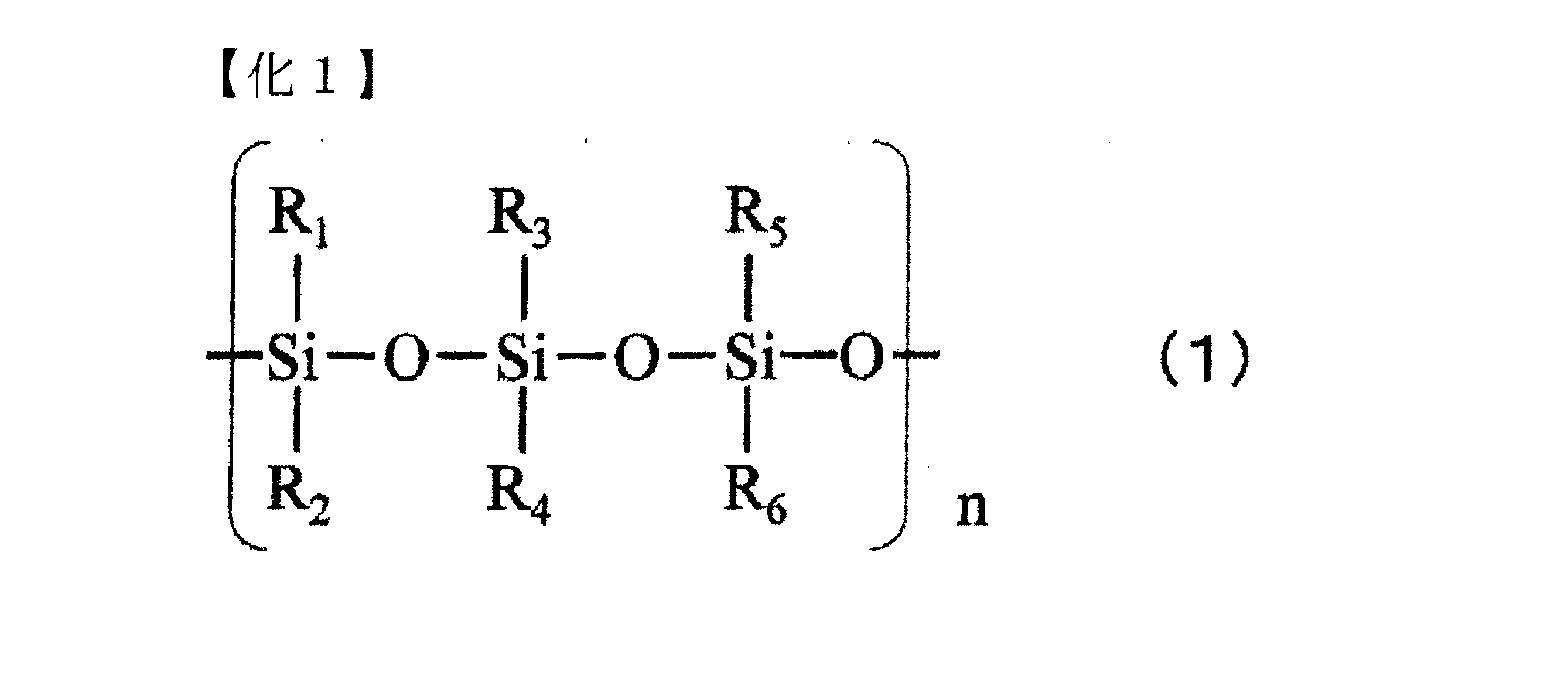
シリコーン骨格としては、例えば、下記の一般式(1)で示されるものが該当する。一般式(1)において、R1、R2、R3、R4、R5、R6はそれぞれ独立に、メチル基、アルキル基、フルオロアルキル基、フェニル基、エポキシ基、アミノ基、カルボキシル基、ポリエーテル基、アクリロイル基、メタクリロイル基等の官能基を有する。また、一般式(1)中、nは1~500の整数であることが好ましい。 An example of the silicone skeleton is one represented by the following general formula (1): In general formula (1), R 1 , R 2 , R 3 , R 4 , R 5 , and R 6 each independently have a functional group such as a methyl group, an alkyl group, a fluoroalkyl group, a phenyl group, an epoxy group, an amino group, a carboxyl group, a polyether group, an acryloyl group, or a methacryloyl group. In general formula (1), n is preferably an integer of 1 to 500.
シリコーン骨格を有する光重合性化合物にシリコーン骨格を有さない化合物を配合して、異方性光拡散フィルムを形成すると、低屈折率領域と高屈折率領域が分離して形成されやすくなり、異方性の程度が強くなり好ましい。 When a photopolymerizable compound having a silicone skeleton is blended with a compound not having a silicone skeleton to form an anisotropic light-diffusing film, the low refractive index region and the high refractive index region are easily formed separately, and the degree of anisotropy becomes stronger, which is preferable.
シリコーン骨格を有さない化合物は、光重合性化合物のほかに熱可塑性樹脂、熱硬化性樹脂を用いることができ、これらを併用することもできる。 Compounds that do not have a silicone skeleton can be photopolymerizable compounds, as well as thermoplastic resins and thermosetting resins, and these can also be used in combination.
光重合性化合物としては、ラジカル重合性又はカチオン重合性の官能基を有するポリマー、オリゴマー、モノマーを使用することができる(ただし、シリコーン骨格を有していないものである)。 As the photopolymerizable compound, a polymer, oligomer, or monomer having a radically polymerizable or cationic polymerizable functional group can be used (however, it does not have a silicone skeleton).
熱可塑性樹脂としては、ポリエステル、ポリエーテル、ポリウレタン、ポリアミド、ポリスチレン、ポリカーボネート、ポリアセタール、ポリ酢酸ビニル、アクリル樹脂とその共重合体や変性物が挙げられる。熱可塑性樹脂を用いる場合においては熱可塑性樹脂が溶解する溶剤を使用して溶解し、塗布、乾燥後に紫外線でシリコーン骨格を有する光重合性化合物を硬化させて異方性光拡散フィルムを成形する。 Thermoplastic resins include polyester, polyether, polyurethane, polyamide, polystyrene, polycarbonate, polyacetal, polyvinyl acetate, acrylic resins, and their copolymers and modified products. When using a thermoplastic resin, it is dissolved in a solvent that dissolves the thermoplastic resin, and after coating and drying, the photopolymerizable compound having a silicone skeleton is cured with ultraviolet light to form an anisotropic light-diffusing film.
熱硬化性樹脂としては、エポキシ樹脂、フェノール樹脂、メラミン樹脂、尿素樹脂、不飽和ポリエステルとその共重合体や変性物が挙げられる。熱硬化性樹脂を用いる場合においては、紫外線でシリコーン骨格を有する光重合性化合物を硬化させた後に適宜加熱することで、熱硬化性樹脂を硬化させて異方性光拡散フィルムを成形する。 Examples of thermosetting resins include epoxy resins, phenolic resins, melamine resins, urea resins, unsaturated polyesters, and their copolymers and modified products. When using a thermosetting resin, a photopolymerizable compound having a silicone skeleton is cured with ultraviolet light, and then appropriately heated to harden the thermosetting resin and form an anisotropic light-diffusing film.
シリコーン骨格を有さない化合物として最も好ましいのは光重合性化合物であり、低屈折率領域と高屈折率領域が分離しやすいことと、熱可塑性樹脂を用いる場合の溶剤が不要で乾燥過程が不要であること、熱硬化性樹脂のような熱硬化過程が不要であること等、生産性に優れている。 The most preferred compounds that do not have a silicone skeleton are photopolymerizable compounds, which have excellent productivity because the low refractive index region and the high refractive index region are easily separated, there is no need for a solvent when using a thermoplastic resin, and no drying process is required, and there is no need for a heat curing process like with thermosetting resins.
<光開始剤>
ラジカル重合性化合物を重合させることのできる光開始剤としては、ベンゾフェノン、ベンジル、ミヒラーズケトン、2-クロロチオキサントン、2,4-ジエチルチオキサントン、ベンゾインエチルエーテル、ベンゾインイソプロピルエーテル、ベンゾインイソブチルエーテル、2,2-ジエトキシアセトフェノン、ベンジルジメチルケタール、2,2-ジメトキシ-1,2-ジフェニルエタン-1-オン、2-ヒドロキシ-2-メチル-1-フェニルプロパン-1-オン、1-ヒドロキシシクロヘキシルフェニルケトン、2-メチル-1-[4-(メチルチオ)フェニル]-2-モルフォリノプロパノン-1、1-[4-(2-ヒドロキシエトキシ)-フェニル]-2-ヒドロキシ-2-メチル-1-プロパン-1-オン、ビス(シクロペンタジエニル)-ビス[2,6-ジフルオロ-3-(ピル-1-イル)フェニル]チタニウム、2-ベンジル-2-ジメチルアミノ-1-(4-モルフォリノフェニル)-ブタノン-1、2,4,6-トリメチルベンゾイルジフェニルフォスフィンオキサイド等が挙げられる。また、これらの化合物は、各単体で用いてもよく、複数混合して用いてもよい。
<Photoinitiator>
Examples of photoinitiators capable of polymerizing radically polymerizable compounds include benzophenone, benzil, Michler's ketone, 2-chlorothioxanthone, 2,4-diethylthioxanthone, benzoin ethyl ether, benzoin isopropyl ether, benzoin isobutyl ether, 2,2-diethoxyacetophenone, benzil dimethyl ketal, 2,2-dimethoxy-1,2-diphenylethane-1-one, 2-hydroxy-2-methyl-1-phenylpropan-1-one, 1-hydroxycyclohexyl ether, and 1-methyl-2-phenylpropan-1-one. phenyl ketone, 2-methyl-1-[4-(methylthio)phenyl]-2-morpholinopropanone-1, 1-[4-(2-hydroxyethoxy)-phenyl]-2-hydroxy-2-methyl-1-propan-1-one, bis(cyclopentadienyl)-bis[2,6-difluoro-3-(pyr-1-yl)phenyl]titanium, 2-benzyl-2-dimethylamino-1-(4-morpholinophenyl)-butanone-1, 2,4,6-trimethylbenzoyldiphenylphosphine oxide, etc. Furthermore, these compounds may be used alone or in combination.
カチオン重合性化合物の光開始剤は、光照射によって酸を発生し、この発生した酸により上述のカチオン重合性化合物を重合させることができる化合物であり、一般的には、オニウム塩、メタロセン錯体が好適に用いられる。 The photoinitiator for the cationic polymerizable compound is a compound that generates an acid when irradiated with light and can polymerize the above-mentioned cationic polymerizable compound using the generated acid. In general, onium salts and metallocene complexes are preferably used.
オニウム塩としては、ジアゾニウム塩、スルホニウム塩、ヨードニウム塩、ホスホニウム塩、セレニウム塩等が使用され、これらの対イオンには、BF4-、PF6-、AsF6-、SbF6-等のアニオンが用いられる。具体例としては、4-クロロベンゼンジアゾニウムヘキサフルオロホスフェート、トリフェニルスルホニウムヘキサフルオロアンチモネート、トリフェニルスルホニウムヘキサフルオロホスフェート、(4-フェニルチオフェニル)ジフェニルスルホニウムヘキサフルオロアンチモネート、(4-フェニルチオフェニル)ジフェニルスルホニウムヘキサフルオロホスフェート、ビス[4-(ジフェニルスルホニオ)フェニル]スルフィド-ビス-ヘキサフルオロアンチモネート、ビス[4-(ジフェニルスルホニオ)フェニル]スルフィド-ビス-ヘキサフルオロホスフェート、(4-メトキシフェニル)ジフェニルスルホニウムヘキサフルオロアンチモネート、(4-メトキシフェニル)フェニルヨードニウムヘキサフルオロアンチモネート、ビス(4-t-ブチルフェニル)ヨードニウムヘキサフルオロホスフェート、ベンジルトリフェニルホスホニウムヘキサフルオロアンチモネート、トリフェニルセレニウムヘキサフルオロホスフェート、(η5-イソプロピルベンゼン)(η5-シクロペンタジエニル)鉄(II)ヘキサフルオロホスフェート等が挙げられるが、これらに限定されるものではない。また、これらの化合物は、各単体で用いてもよく、複数混合して用いてもよい。 As the onium salt, a diazonium salt, a sulfonium salt, an iodonium salt, a phosphonium salt, a selenium salt, etc. are used, and as the counter ion, an anion such as BF4-, PF6-, AsF6-, SbF6-, etc. are used. Specific examples include 4-chlorobenzenediazonium hexafluorophosphate, triphenylsulfonium hexafluoroantimonate, triphenylsulfonium hexafluorophosphate, (4-phenylthiophenyl)diphenylsulfonium hexafluoroantimonate, (4-phenylthiophenyl)diphenylsulfonium hexafluorophosphate, bis[4-(diphenylsulfonio)phenyl]sulfide-bis-hexafluoroantimonate, bis[4-(diphenylsulfonio)phenyl]sulfide-bis-hexafluoroantimonate, and bis[4-(diphenylsulfonio)phenyl]sulfide-bis-hexafluorophosphate. Examples of the compounds include, but are not limited to, fluorophosphate, (4-methoxyphenyl)diphenylsulfonium hexafluoroantimonate, (4-methoxyphenyl)phenyliodonium hexafluoroantimonate, bis(4-t-butylphenyl)iodonium hexafluorophosphate, benzyltriphenylphosphonium hexafluoroantimonate, triphenylselenium hexafluorophosphate, (η5-isopropylbenzene)(η5-cyclopentadienyl)iron(II) hexafluorophosphate, and the like. These compounds may be used alone or in combination.
光開始剤は、光重合性化合物質量100に対し、0.01質量部~10質量部程度配合されることが好ましく、好ましくは0.1質量部~7質量部程度配合されることがより好ましく、0.1質量部~5質量部程度配合されることがさらに好ましい。これは、0.01質量部未満では光硬化性が低下し、10質量部を超えて配合した場合には、表面だけが硬化して内部の硬化性が低下してしまう弊害、着色、柱状構造の形成の阻害を招くからである。 The photoinitiator is preferably blended in an amount of about 0.01 to 10 parts by mass, more preferably about 0.1 to 7 parts by mass, and even more preferably about 0.1 to 5 parts by mass, per 100 parts by mass of the photopolymerizable compound. This is because if it is less than 0.01 parts by mass, the photocurability decreases, and if it is blended in more than 10 parts by mass, only the surface will harden and the internal curability will decrease, which will lead to coloring and inhibition of the formation of columnar structures.
<その他の成分>
光開始剤は、通常粉体を光重合性化合物中に直接溶解して使用されるが、溶解性が悪い場合は光開始剤を予め極少量の溶剤に高濃度に溶解させたものを使用することもできる。このような溶剤としては光重合性であることがさらに好ましく、具体的には炭酸プロピレン、γ-ブチロラクトン等が挙げられる。また、光重合性を向上させるために公知の各種染料や増感剤を添加することも可能である。
<Other ingredients>
The photoinitiator is usually used by directly dissolving the powder in the photopolymerizable compound, but if the solubility is poor, the photoinitiator can be used by dissolving it in a very small amount of solvent at a high concentration in advance. It is more preferable that such a solvent is photopolymerizable, and specific examples include propylene carbonate and γ-butyrolactone. It is also possible to add various known dyes and sensitizers to improve photopolymerizability.
さらに、光重合性化合物を加熱により硬化させることのできる熱硬化開始剤を光開始剤と共に併用することもできる。この場合、光硬化の後に加熱することにより光重合性化合物の重合硬化をさらに促進し完全なものにすることが期待できる。光重合性化合物を単独で、又は複数を混合した組成物を硬化させて、異方性光拡散フィルムを形成することができる。 Furthermore, a heat-curing initiator capable of curing the photopolymerizable compound by heating can be used together with the photoinitiator. In this case, it is expected that the polymerization and curing of the photopolymerizable compound can be further promoted and completed by heating after photocuring. An anisotropic light-diffusing film can be formed by curing a single photopolymerizable compound or a composition in which multiple photopolymerizable compounds are mixed.
光重合性化合物と光硬化性を有しない高分子樹脂の混合物を硬化させることによっても異方性光拡散フィルム形成することができる。 An anisotropic light-diffusing film can also be formed by curing a mixture of a photopolymerizable compound and a polymer resin that is not photocurable.
ここで使用できる高分子樹脂としては、アクリル樹脂、スチレン樹脂、スチレン-アクリル共重合体、ポリウレタン樹脂、ポリエステル樹脂、エポキシ樹脂、セルロース系樹脂、酢酸ビニル系樹脂、塩化ビニル-酢酸ビニル共重合体、ポリビニルブチラール樹脂等が挙げられる。これらの高分子樹脂と光重合性化合物は、光硬化前は十分な相溶性を有していることが必要であるが、この相溶性を確保するために各種有機溶剤や可塑剤等を使用することも可能である。 Polymer resins that can be used here include acrylic resins, styrene resins, styrene-acrylic copolymers, polyurethane resins, polyester resins, epoxy resins, cellulose-based resins, vinyl acetate-based resins, vinyl chloride-vinyl acetate copolymers, polyvinyl butyral resins, etc. These polymer resins and photopolymerizable compounds must have sufficient compatibility before photocuring, and various organic solvents and plasticizers can be used to ensure this compatibility.
光重合性化合物としてアクリレートを使用する場合は、高分子樹脂としてはアクリル樹脂から選択することが相溶性の点で好ましい。 When using an acrylate as the photopolymerizable compound, it is preferable to select an acrylic resin as the polymer resin in terms of compatibility.
シリコーン骨格を有する光重合性化合物と、シリコーン骨格を有さない化合物の比率は質量比で15:85~85:15の範囲にあることが好ましい。より好ましくは30:70~70:30の範囲である。当該範囲にすることによって、低屈折率領域と高屈折率領域の相分離が進みやすくなるとともに、柱状領域が傾斜しやすくなる。シリコーン骨格を有する光重合性化合物の比率が下限値未満又は上限値超であると、相分離が進みにくくなってしまい、柱状領域が傾斜しにくくなる。 The ratio of the photopolymerizable compound having a silicone skeleton to the compound not having a silicone skeleton is preferably in the range of 15:85 to 85:15 by mass. More preferably, it is in the range of 30:70 to 70:30. By setting it in this range, phase separation between the low refractive index region and the high refractive index region is more likely to proceed, and the columnar region is more likely to tilt. If the ratio of the photopolymerizable compound having a silicone skeleton is less than the lower limit or more than the upper limit, phase separation is less likely to proceed, and the columnar region is less likely to tilt.
シリコーン骨格を有する光重合性化合物としてシリコーン・ウレタン・(メタ)アクリレートを使用すると、シリコーン骨格を有さない化合物との相溶性が向上する。これによって、材料の混合比率を幅広くしても柱状領域を傾斜させることができる。 When silicone urethane (meth)acrylate is used as a photopolymerizable compound with a silicone skeleton, compatibility with compounds that do not have a silicone skeleton is improved. This makes it possible to tilt the columnar regions even when the material mixing ratio is wide.
光重合性化合物を含む組成物を調製する際の溶剤としては、例えば、酢酸エチル、酢酸ブチル、アセトン、メチルエチルケトン、メチルイソブチルケトン、シクロヘキサノン、トルエン、キシレン等を使用することができる。 For example, ethyl acetate, butyl acetate, acetone, methyl ethyl ketone, methyl isobutyl ketone, cyclohexanone, toluene, xylene, etc. can be used as a solvent when preparing a composition containing a photopolymerizable compound.
<<製造プロセス>>
次に、異方性光拡散フィルム用組成物を用いた、異方性光拡散フィルムの製造プロセスについて説明する。
<<Manufacturing process>>
Next, a process for producing an anisotropic light-diffusing film using the composition for an anisotropic light-diffusing film will be described.
まず、上述の異方性光拡散フィルム用組成物(以下、「光硬化樹脂組成物」と称する場合がある)を、透明PETフィルムのような適当な基体上に塗布してシート状に設け、成膜し、必要に応じて乾燥し溶剤を揮発させて未硬化樹脂組成物層を設ける。この未硬化樹脂組成物層上に光を照射することで、異方性光拡散フィルムを作製することができる。 First, the above-mentioned composition for anisotropic light-diffusing films (hereinafter sometimes referred to as "photocurable resin composition") is applied to a suitable substrate such as a transparent PET film to form a sheet, which is then dried as necessary to volatilize the solvent to provide an uncured resin composition layer. An anisotropic light-diffusing film can be produced by irradiating light onto this uncured resin composition layer.
より具体的には、異方性光拡散フィルムの形成工程は、主に、以下の工程を有するものである。
(1)工程1-1:未硬化樹脂組成物層を基体上に設ける工程
(2)工程1-2:光源から平行光線を得る工程
(3)任意工程1-3:指向性をもった光線を得る工程
(4)工程1-4:未硬化樹脂組成物層を硬化させる工程
More specifically, the process for forming the anisotropic light-diffusing film mainly includes the following steps.
(1) Step 1-1: A step of providing an uncured resin composition layer on a substrate (2) Step 1-2: A step of obtaining a parallel light beam from a light source (3) Optional Step 1-3: A step of obtaining a directional light beam (4) Step 1-4: A step of curing the uncured resin composition layer
<工程1-1:未硬化樹脂組成物層を基体上に設ける工程>
光硬化樹脂組成物を、基体上に、シート状に、未硬化樹脂組成物層として設ける手法は、通常の塗工方式や印刷方式が適用される。具体的には、エアドクターコーティング、バーコーティング、ブレードコーティング、ナイフコーティング、リバースコーティング、トランスファロールコーティング、グラビアロールコーティング、キスコーティング、キャストコーティング、スプレーコーティング、スロットオリフィスコーティング、カレンダーコーティング、ダムコーティング、ディップコーティング、ダイコーティング等のコーティングや、グラビア印刷等の凹版印刷、スクリーン印刷等の孔版印刷等の印刷等が使用できる。組成物が低粘度の場合は、基体の周囲に一定の高さの堰を設けて、この堰で囲まれた中に組成物をキャストすることもできる。
<Step 1-1: Step of Providing Uncured Resin Composition Layer on Substrate>
The photocurable resin composition is provided on the substrate in the form of a sheet as an uncured resin composition layer by a normal coating method or printing method.Specifically, coating such as air doctor coating, bar coating, blade coating, knife coating, reverse coating, transfer roll coating, gravure roll coating, kiss coating, cast coating, spray coating, slot orifice coating, calendar coating, dam coating, dip coating, die coating, intaglio printing such as gravure printing, stencil printing such as screen printing, etc. can be used.When the composition has a low viscosity, a dam of a certain height can be provided around the substrate, and the composition can be cast into the area surrounded by the dam.
工程1-1において、未硬化樹脂組成物層の酸素阻害を防止して、異方性光拡散フィルムの特徴である柱状領域を効率良く形成させるために、未硬化樹脂組成物層の光照射側に密着して光の照射強度を局所的に変化させるマスクを積層することも可能である。 In step 1-1, in order to prevent oxygen inhibition of the uncured resin composition layer and efficiently form the columnar regions that are characteristic of anisotropic light-diffusing films, it is also possible to laminate a mask that adheres closely to the light-irradiated side of the uncured resin composition layer and locally changes the light irradiation intensity.
マスクの材質としては、カーボン等の光吸収性のフィラーをマトリックス中に分散したもので、入射光の一部はカーボンに吸収されるが、開口部は光が十分に透過できるような構成のものが好ましい。このようなマトリックスとしては、PET、TAC、PVAc、PVA、アクリル、ポリエチレン等の透明プラスチックや、ガラス、石英等の無機物や、これらのマトリックスを含むシートに紫外線透過量を制御するためのパターニングや紫外線を吸収する顔料を含んだものであっても構わない。 The mask material is preferably one in which light-absorbing fillers such as carbon are dispersed in a matrix, so that part of the incident light is absorbed by the carbon, but the openings are configured to allow sufficient light to pass through. Such matrices may be transparent plastics such as PET, TAC, PVAc, PVA, acrylic, and polyethylene, inorganic materials such as glass and quartz, or sheets containing these matrices that are patterned to control the amount of UV light transmitted or contain pigments that absorb UV light.
このようなマスクを用いない場合には、窒素雰囲気下で光照射を行うことで、未硬化樹脂組成物層の酸素阻害を防止することも可能である。また、通常の透明フィルムを未硬化樹脂組成物層上に積層するだけでも、酸素阻害を防ぎ柱状領域の形成を促す上で有効である。このようなマスクや透明フィルムを介した光照射では、光硬化樹脂組成物中に、その照射強度に応じた光重合反応を生じるため、屈折率分布を生じ易く、本形態に係る異方性光拡散フィルムの作製に有効である。 When such a mask is not used, it is also possible to prevent oxygen inhibition of the uncured resin composition layer by performing light irradiation under a nitrogen atmosphere. In addition, simply laminating a normal transparent film on the uncured resin composition layer is also effective in preventing oxygen inhibition and promoting the formation of columnar regions. When light is irradiated through such a mask or transparent film, a photopolymerization reaction occurs in the photocurable resin composition according to the irradiation intensity, which makes it easy to generate a refractive index distribution, and is effective in producing the anisotropic light-diffusing film of this embodiment.
<工程1-2:光源から平行光線を得る工程>
光源としては、通常はショートアークの紫外線発生光源が使用され、具体的には高圧水銀灯、低圧水銀灯、メタハライドランプ、キセノンランプ等が使用可能である。このとき、所望の散乱中心軸と平行な光線を得る必要があるが、このような平行光線は、例えば点光源を配置して、この点光源と未硬化樹脂組成物層の間に平行光線を照射するためのフレネルレンズ等の光学レンズを配置する他、光源の背後に反射鏡を配置して、所定の方向に点光源として光が出射するようにすること等で、得ることができる。
<Step 1-2: Step of obtaining parallel light from a light source>
As the light source, a short-arc ultraviolet light source is usually used, and specifically, a high-pressure mercury lamp, a low-pressure mercury lamp, a metahalide lamp, a xenon lamp, etc., can be used. At this time, it is necessary to obtain a light beam parallel to the desired scattering central axis, and such a parallel light beam can be obtained, for example, by arranging a point light source and arranging an optical lens such as a Fresnel lens for irradiating a parallel light beam between the point light source and the uncured resin composition layer, or by arranging a reflecting mirror behind the light source so that light is emitted as a point light source in a predetermined direction.
<任意工程1-3:指向性をもった光線を得る工程>
任意工程1-3は、平行光線を指向性拡散素子に入射させ、指向性をもった光線を得る工程である。図9は、本発明に係る任意工程1-3における異方性光拡散フィルムの製造方法を示す模式図である。
<Optional step 1-3: Step of obtaining a directional light beam>
Optional step 1-3 is a step of making parallel light incident on a directional diffusion element to obtain a directional light beam. Fig. 9 is a schematic diagram showing a method for producing an anisotropic light-diffusing film in optional step 1-3 according to the present invention.
任意工程1-3で用いられる指向性拡散素子301及び302は、光源300から入射した平行光線Dに指向性を付与するものであればよい。
The
図9においては指向性をもった光Eが、X方向に多く拡散し、Y方向にはほとんど拡散しない態様にて、未硬化樹脂組成物層303に入射することを記載している。このように指向性をもった光を得るためには、例えば、指向性拡散素子301及び302内に、アスペクト比の高い針状フィラーを含有させるとともに、当該針状フィラーをY方向に長軸方向が延存するように配向させる方法を採用することができる。指向性拡散素子301及び302は、針状フィラーを使用する方法以外に、種々の方法を使用することができる。
Figure 9 shows that directional light E is incident on the uncured
ここで、指向性をもった光Eのアスペクト比は、2~20とすることが好ましい。当該アスペクト比にほぼ対応した、アスペクト比を有する柱状領域が形成される。上記アスペクト比の上限値は、10以下であることがより好ましく、5以下であることがさらに好ましい。アスペクト比が20超では、干渉虹やギラツキを生じるおそれがある。 Here, the aspect ratio of the directional light E is preferably 2 to 20. A columnar region having an aspect ratio roughly corresponding to the aspect ratio is formed. The upper limit of the aspect ratio is more preferably 10 or less, and even more preferably 5 or less. If the aspect ratio exceeds 20, there is a risk of interference rainbows and glare.
任意工程1-3においては、指向性をもった光Eの広がりを調整することにより、形成される柱状領域の大きさ(アスペクト比、短径SA、長径LA等)を適宜定めることができる。例えば、図9(a)、(b)のいずれにおいても、本形態の異方性光拡散フィルムを得ることができる。図9の(a)と(b)で異なるのは、指向性をもった光Eの広がりが、(a)では大きいのに対し(b)では小さいことである。指向性をもった光Eの広がりの大きさに依存して、柱状領域の大きさが異なることとなる。 In optional step 1-3, the size (aspect ratio, minor axis SA, major axis LA, etc.) of the columnar region to be formed can be appropriately determined by adjusting the spread of the directional light E. For example, the anisotropic light-diffusing film of this embodiment can be obtained in either FIG. 9(a) or (b). The difference between FIG. 9(a) and (b) is that the spread of the directional light E is large in (a) but small in (b). The size of the columnar region differs depending on the size of the spread of the directional light E.
指向性をもった光Eの広がりは、主に指向性拡散素子301及び302の種類と、未硬化樹脂組成物層303との距離に依存する。当該距離を短くするにつれ柱状領域の大きさは小さくなり、長くするにつれ柱状領域の大きさは大きくなる。従って、当該距離を調整することにより、柱状領域の大きさを調整することができる。
The spread of the directional light E depends mainly on the type of
<工程1-4:未硬化樹脂組成物層を硬化させる工程>
未硬化樹脂組成物層に照射して、未硬化樹脂組成物層を硬化させる光線は、光重合性化合物を硬化可能な波長を含んでいることが必要で、通常は水銀灯の365nmを中心とする波長の光が利用される。この波長帯を使って異方性光拡散フィルムを作製する場合、照度としては0.01mW/cm2~100mW/cm2の範囲が好ましく、0.1mW/cm2~20mW/cm2 がより好ましい。照度が0.01mW/cm2未満であると、硬化に長時間を要するため、生産効率が悪くなり、100mW/cm2を超えると、光重合性化合物の硬化が速すぎて構造形成を生じず、目的の光学特性を発現できなくなるからである。
<Step 1-4: Step of curing the uncured resin composition layer>
The light irradiated to the uncured resin composition layer to cure the uncured resin composition layer must contain a wavelength capable of curing the photopolymerizable compound, and light with a wavelength centered at 365 nm from a mercury lamp is usually used. When using this wavelength band to produce an anisotropic light-diffusing film, the illuminance is preferably in the range of 0.01 mW/cm 2 to 100 mW/cm 2 , and more preferably 0.1 mW/cm 2 to 20 mW/cm 2. If the illuminance is less than 0.01 mW/cm 2 , it takes a long time to cure, resulting in poor production efficiency, and if it exceeds 100 mW/cm 2 , the curing of the photopolymerizable compound is too fast to form a structure, making it impossible to express the desired optical properties.
なお、光の照射時間は特に限定されないが、10秒間~180秒間が好ましく、30秒間~120秒間がより好ましい。上記光線を照射することで、本形態の異方性光拡散フィルムを得ることができる。 The light irradiation time is not particularly limited, but is preferably 10 to 180 seconds, and more preferably 30 to 120 seconds. By irradiating the light beam, the anisotropic light diffusion film of this embodiment can be obtained.
異方性光拡散フィルムは、上述の如く、低照度の光を比較的長時間照射することにより、未硬化樹脂組成物層中に、特定の内部構造が形成されることで得られるものである。そのため、このような光照射だけでは未反応のモノマー成分が残存して、べたつきを生じたりしてハンドリング性や耐久性に問題がある場合がある。そのような場合は、1000mW/cm2以上の高照度の光を追加照射して残存モノマーを重合させることができる。このときの光照射はマスクを積層した側の逆側から行ってもよい。 As described above, the anisotropic light diffusion film is obtained by forming a specific internal structure in the uncured resin composition layer by irradiating low-intensity light for a relatively long time. Therefore, such light irradiation alone may leave unreacted monomer components, causing stickiness and problems in handling and durability. In such cases, the remaining monomers can be polymerized by additionally irradiating high-intensity light of 1000 mW/cm2 or more . The light irradiation at this time may be performed from the opposite side to the side where the mask is laminated.
前述したように、未硬化樹脂組成物層を硬化させる際に、未硬化樹脂組成物層に照射される光の角度を調整することにより、得られる異方性光拡散フィルムの散乱中心軸を所望のものとすることができる。 As described above, when curing the uncured resin composition layer, the angle of light irradiated onto the uncured resin composition layer can be adjusted to obtain the desired scattering central axis of the resulting anisotropic light-diffusing film.
<<<<異方性光拡散フィルム積層体の用途>>>>
異方性光拡散フィルム積層体は、視角依存性改善効果に優れることから、液晶表示装置、有機EL表示装置、プラズマディスプレイ等のあらゆる表示装置に適用することができる。異方性光拡散フィルム積層体は、視角依存性の問題が生じ易いTN方式の液晶においても特に好ましく使用することができる。その際、優れた視角依存性改善効果を発現させるため、異方性光拡散フィルムbが、異方性光拡散フィルムaよりも視認側となるよう、積層されることが好ましい。
<<<<<Applications of anisotropic light-diffusing film laminates>>>>
The anisotropic light-diffusing film laminate has an excellent effect of improving the viewing angle dependency, and therefore can be applied to all kinds of displays such as liquid crystal displays, organic EL displays, and plasma displays. The anisotropic light-diffusing film laminate can be particularly preferably used in TN-type liquid crystal displays that are prone to problems with viewing angle dependency. In this case, in order to achieve an excellent effect of improving the viewing angle dependency, it is preferable that the anisotropic light-diffusing film b is laminated so as to be closer to the viewing side than the anisotropic light-diffusing film a.
ここで、本発明によれば、液晶層と、異方性光拡散フィルム積層体と、を含む液晶表示装置を提供することが可能である。この場合、異方性光拡散フィルム積層体は、液晶層よりも視認側に設けられている(積層されている)。液晶表示装置は、TN方式、VA方式、IPS方式等のいずれでもよい。より具体的には、一般的な液晶装置は、表示装置から視認側に向かって、光源、偏光板、ガラス基板、透明電極膜、液晶層、透明電極膜、カラーフィルター、ガラス基板、偏光板の順番で積層された層構造を有し、また、適宜の機能層を更に有するが、異方性光拡散フィルム積層体は、液相層よりも視認側となるいずれの箇所に設けられていてもよい。 Here, according to the present invention, it is possible to provide a liquid crystal display device including a liquid crystal layer and an anisotropic light-diffusing film laminate. In this case, the anisotropic light-diffusing film laminate is provided (laminated) on the viewing side of the liquid crystal layer. The liquid crystal display device may be any of the TN type, VA type, IPS type, etc. More specifically, a typical liquid crystal device has a layer structure in which a light source, a polarizing plate, a glass substrate, a transparent electrode film, a liquid crystal layer, a transparent electrode film, a color filter, a glass substrate, and a polarizing plate are laminated in this order from the display device toward the viewing side, and further has an appropriate functional layer, but the anisotropic light-diffusing film laminate may be provided at any location on the viewing side of the liquid phase layer.
また、本発明によれば、発光層と、異方性光拡散フィルム積層体と、を含む有機EL表示装置を提供することが可能である。この場合、異方性光拡散フィルム積層体は、発光層(発光層に接続された電極を含む。)よりも視認側に設けられている(積層されている)。有機EL表示装置は、トップエミッション方式、ボトムエミッション方式等のいずれの方式でもよいし、また、カラーの有機EL表示装置である場合には、RGB塗り分け方式、カラーフィルター方式等のいずれの方式でもよい。また、有機EL表示は、更に多層化されたものであってもよい。 According to the present invention, it is also possible to provide an organic EL display device including a light-emitting layer and an anisotropic light-diffusing film laminate. In this case, the anisotropic light-diffusing film laminate is provided (laminated) on the viewing side of the light-emitting layer (including the electrode connected to the light-emitting layer). The organic EL display device may be of any of the top emission type and bottom emission type, and in the case of a color organic EL display device, it may be of any of the RGB coloring type and color filter type. The organic EL display may also be further multi-layered.
<<<実施例>>>
次に、本発明を実施例及び比較例により、更に具体的に説明するが、本発明は、これらの例によって何ら限定されるものではない。
<<<<Example>>>
EXAMPLES Next, the present invention will be described more specifically with reference to examples and comparative examples, but the present invention is not limited to these examples in any way.
<<異方性光学フィルム>>
厚み100μmのPETフィルム(東洋紡社製、商品名:A4300)の縁部全周に、ディスペンサーを使い、硬化性樹脂で高さ30~60μmの隔壁を形成した。この中に下記の紫外線硬化樹脂組成物を滴下し、30μm~60μm厚みの液膜とし、別のPETフィルムでカバーした。
<<Anisotropic Optical Film>>
A partition wall having a height of 30 to 60 μm was formed with a curable resin using a dispenser around the entire edge of a 100 μm thick PET film (manufactured by Toyobo Co., Ltd., product name: A4300). The following ultraviolet curable resin composition was dropped into this to form a liquid film having a thickness of 30 μm to 60 μm, and this was covered with another PET film.
・シリコーン・ウレタン・アクリレート(屈折率:1.460、重量平均分子量:5890) 20重量部
(RAHN社製、商品名:00-225/TM18)
・ネオペンチルグリコールジアクリレート(屈折率:1.450) 30重量部
(ダイセルサイテック社製、商品名Ebecryl145)
・ビスフェノールAのEО付加物ジアクリレート(ダイセルサイテック社製、商品名Ebecryl150、屈折率:1.536) 15重量部
・フェノキシエチルアクリレート(共栄社化学製、商品名:ライトアクリレートPО-A、屈折率1.518) 40重量部
・2,2-ジメトキシ-1,2-ジフェニルエタン-1-オン(BASF社製、商品名:Irgacure651) 4重量部
Silicone urethane acrylate (refractive index: 1.460, weight average molecular weight: 5890) 20 parts by weight (manufactured by RAHN, product name: 00-225/TM18)
Neopentyl glycol diacrylate (refractive index: 1.450) 30 parts by weight
(Manufactured by Daicel Cytec, product name Ebecryl 145)
Bisphenol A EO adduct diacrylate (manufactured by Daicel Cytec, product name Ebecryl 150, refractive index: 1.536) 15 parts by weight Phenoxyethyl acrylate (manufactured by Kyoeisha Chemical, product name: Light Acrylate PO-A, refractive index 1.518) 40 parts by
この両面をPETフィルムで挟まれた液膜に対して、UVスポット光源(浜松ホトニクス社製、商品名:L2859-01)の落射用照射ユニットから、照射強度10mW/cm2~100mW/cm2の平行光線である紫外線を、直接、又はPMMAレンズを介して照射した。
ここでPMMAレンズを介した照射では、紫外線照射の際、平行光線をPMMAレンズを用いて水平方向に広げることで柱状領域のアスペクト比を調整した。
さらに、平行光線又は水平方向に広げた平行光線を照射する際の液膜温度、照射角度等を調整することで、当該異方性光拡散フィルムの傾斜方向における最大直線透過率、散乱中心軸角度、ヘイズ値の調整を行った。
以上のパラメータ調整を行うことで、表1の光学特性を有する異方性光拡散フィルム1~15を得た。
The liquid film sandwiched between PET films on both sides was irradiated with parallel ultraviolet light having an intensity of 10 mW/cm 2 to 100 mW/cm 2 from an epi-illumination unit of a UV spot light source (manufactured by Hamamatsu Photonics, product name: L2859-01) either directly or through a PMMA lens.
In the case of irradiation through a PMMA lens, the aspect ratio of the columnar region was adjusted by spreading the parallel light beam in the horizontal direction during ultraviolet irradiation using the PMMA lens.
Furthermore, by adjusting the liquid film temperature, irradiation angle, etc. when irradiating parallel light or parallel light spread in the horizontal direction, the maximum linear transmittance in the inclination direction, scattering central axis angle, and haze value of the anisotropic light-diffusing film were adjusted.
By adjusting the parameters as described above, anisotropic light-diffusing
<異方性光拡散フィルムの厚みの測定>
実施例で得られた異方性光拡散フィルムのフィルムに対し、マイクロメーター(ミツトヨ社製)を用いて測定を行った。測定値は、異方性光拡散フィルムの平面における4つの角付近と、平面における中央付近の1箇所とを含む計5箇所で測定した値の平均値を、異方性光拡散フィルムの厚みとした。
<Measurement of thickness of anisotropic light-diffusing film>
The anisotropic light-diffusing film obtained in the examples was measured using a micrometer (manufactured by Mitutoyo Corporation). The average value of the measurements taken at five points including the four corners and one point near the center of the plane of the anisotropic light-diffusing film was taken as the thickness of the anisotropic light-diffusing film.
<異方性光拡散フィルムの散乱中心軸の角度及び直線透過率の測定>
図6に示すような、光源1の投光角、検出器2の受光角を任意に可変できる変角光度計ゴニオフォトメータ(ジェネシア社製)を用いて、実施例で得られた異方性光拡散フィルムの直線透過率の測定を行った。
固定された光源1からの直進光Iを受ける位置に検出器2を固定し、その間のサンプルホルダーに実施例で得られた異方性光拡散フィルムをセットした。その際、図3に示すTD方向を図6に示す直線Vの直線方向とするよう設置した(この直線Vは、散乱中心軸の傾斜方位に対し、垂直な異方性光拡散フィルム上の線である)。
続いて、直線Vを軸として異方性光拡散フィルムを回転させて、異方性光拡散フィルムを直進透過して検出器2に入る直線透過光量を測定した。その後、直線透過光量より直線透過率を算出し、この直線透過率を角度ごとにプロットして光学プロファイルを作成した。
尚、直線透過光率の測定は、視感度フィルターを用いて可視光領域の波長において測定した。
以上のような測定の結果得られた光学プロファイルに基づき、直線透過率の最大値(最大直線透過率)及び最小値(最小直線透過率)と、当該光学プロファイルにおける最小値に挟まれた略中央部(拡散領域の中央部)より散乱中心軸角度とを求めた。
<Measurement of the Angle of the Scattering Axis and the Linear Transmittance of the Anisotropic Light Diffusion Film>
The linear transmittance of the anisotropic light-diffusing film obtained in the examples was measured using a variable angle goniophotometer (manufactured by Genesia) that can arbitrarily change the projection angle of the
A
Next, the anisotropic light-diffusing film was rotated about the axis of line V to measure the amount of linear transmitted light that passed straight through the anisotropic light-diffusing film and entered the
The linear transmittance was measured at wavelengths in the visible light region using a visibility filter.
Based on the optical profile obtained as a result of the above measurements, the maximum value (maximum linear transmittance) and minimum value (minimum linear transmittance) of the linear transmittance, and the scattering central axis angle were determined from the approximate center part (center part of the diffusion region) sandwiched between the minimum values in the optical profile.
<柱状構造体のアスペクト比の測定(異方性光拡散フィルムの表面観察)>
実施例で得られた異方性光拡散フィルム表面の柱状領域の柱軸に垂直な断面(紫外線照射時の照射光側)を光学顕微鏡で観察し、柱状領域の長径LA及び短径SAを測定した。平均長径LA及び平均短径SAの算出には、任意の20の柱状領域の平均値とした。また、求めた平均長径LA及び平均短径SAに対し、平均長径LA/平均短径SAをアスペクト比として算出した。
<Measurement of the aspect ratio of columnar structures (surface observation of anisotropic light-diffusing film)>
The cross section perpendicular to the column axis of the columnar region on the surface of the anisotropic light-diffusing film obtained in the examples (the side of the light irradiated during ultraviolet irradiation) was observed with an optical microscope, and the major axis LA and minor axis SA of the columnar region were measured. The average major axis LA and the average minor axis SA were calculated as the average values of 20 arbitrary columnar regions. In addition, the average major axis LA/average minor axis SA was calculated as the aspect ratio for the average major axis LA and the average minor axis SA.
<異方性光拡散フィルムのヘイズの測定>
ヘイズメーターNDH-2000(日本電色工業社製)を用いて、実施例で得られた異方性光拡散フィルムのヘイズ値の測定を行った。
<Measurement of Haze of Anisotropic Light Diffusion Film>
The haze value of the anisotropic light-diffusing film obtained in the examples was measured using a haze meter NDH-2000 (manufactured by Nippon Denshoku Industries Co., Ltd.).
<<異方性光拡散フィルム積層体>>
以下に示す方法にて、異方性光拡散フィルム積層体を作製した。
<<Anisotropic Light Diffusion Film Laminate>>
An anisotropic light-diffusing film laminate was produced by the method described below.
<実施例1>
実施例で得られた異方性光拡散フィルム1及び異方性光拡散フィルム2を、長辺方向が異方性光拡散フィルムの散乱中心軸方位と一致するように矩形形状に切り出した後、異方性光拡散フィルム1及び異方性光拡散フィルム2の各散乱中心軸の方位同士がなす角度(φab)が表2に示す目標値0°となるようにアクリル系の樹脂よりなる透明粘着剤の粘着層を介して積層することで、実施例1の異方性光拡散フィルム積層体1を得た。また、表2に示すように、積層後の測定顕微鏡によるφab実測値は、1°であった。
なお、表2に示すように、異方性光拡散フィルム2を異方性光拡散フィルムa、異方性光拡散フィルム1を異方性光拡散フィルムbとした。
Example 1
The anisotropic light-diffusing
As shown in Table 2, the anisotropic light-diffusing
<実施例2~7、比較例1~8>
使用する2種の異方性光拡散フィルムを、表2に記載の組み合わせに従い、且つ、φabが表2に示す目標値となるようにアクリル系の樹脂よりなる透明粘着剤の粘着層を介して積層した他は、実施例1と同様に作製を行い、実施例2~7、比較例1~8の異方性光拡散フィルム積層体2~15を得た。各異方性光拡散フィルム積層後の測定顕微鏡によるφab実測値を、表2に示す。
<Examples 2 to 7, Comparative Examples 1 to 8>
The two types of anisotropic light - diffusing films used were laminated in the same manner as in Example 1, except that they were laminated via an adhesive layer of a transparent adhesive made of an acrylic resin in accordance with the combinations shown in Table 2 so that φ ab was the target value shown in Table 2, to obtain anisotropic light-diffusing
<<評価方法>>
実施例及び比較例の異方性光拡散フィルム積層体に関し、以下のようにして評価を行った。
<<Evaluation method>>
The anisotropic light-diffusing film laminates of the Examples and Comparative Examples were evaluated as follows.
<異方性光拡散フィルム積層体のヘイズ値の測定>
ヘイズメーターNDH-2000(日本電色工業社製)を用いて、実施例で得られた異方性光拡散フィルム積層体のヘイズ値の測定を行った。
<Measurement of Haze Value of Anisotropic Light-Diffusing Film Laminate>
The haze value of the anisotropic light-diffusing film laminate obtained in each example was measured using a haze meter NDH-2000 (manufactured by Nippon Denshoku Industries Co., Ltd.).
<異方性光拡散フィルム積層体の直線透過率の測定>
図6に示すような、光源1の投光角、検出器2の受光角を任意に可変できる変角光度計ゴニオフォトメータ(ジェネシア社製)を用いて、実施例及び比較例で得られた異方性光拡散フィルム積層体の直線透過率の測定を行った。
固定された光源1からの直進光Iを受ける位置に検出器2を固定し、その間のサンプルホルダーに実施例及び比較例で得られた異方性光拡散フィルム積層体をセットした。その際、異方性光拡散フィルム積層体の視認側となる異方性光拡散フィルムに対し、図3に示すMD方向を図6に示す直線Vの直線方向とするよう設置した(この直線Vは、散乱中心軸の傾斜方位に対し、垂直な異方性光拡散フィルム積層体上の線である)。
続いて、直線Vを軸として異方性光拡散フィルム積層体を回転させて、異方性光拡散フィルム積層体を直進透過して検出器2に入る直線透過光量を測定した。その後、直線透過光量より直線透過率を算出し、この直線透過率を角度ごとにプロットして光学プロファイルを作成した。
尚、直線透過光率の測定は、視感度フィルターを用いて可視光領域の波長において測定した。
以上のような測定の結果得られた光学プロファイルに基づき、直線透過率の最大値(最大直線透過率)及び最小値(最小直線透過率)と、入射光角度0°における直線透過率とを求めた。
<Measurement of In-Line Transmittance of Anisotropic Light-Diffusing Film Laminate>
The linear transmittance of the anisotropic light-diffusing film laminates obtained in the examples and comparative examples was measured using a variable angle goniophotometer (manufactured by Genesia) that can arbitrarily change the projection angle of the
A
Next, the anisotropic light-diffusing film laminate was rotated about the axis of line V to measure the amount of linear transmitted light that passed straight through the anisotropic light-diffusing film laminate and entered the
The linear transmittance was measured at wavelengths in the visible light region using a visibility filter.
Based on the optical profile obtained as a result of the above measurements, the maximum value (maximum linear transmittance) and minimum value (minimum linear transmittance) of the linear transmittance, and the linear transmittance at an incident light angle of 0° were determined.
<コントラスト・階調反転の評価>
実施例及び比較例の異方性光拡散フィルム積層体を、TNモードの液晶ディスプレイ表面上に、液晶ディスプレイの階調反転が生じる方向に対する方位と、異方性光拡散フィルムaの散乱中心軸の傾斜方向に対する方位となす角が0°となるように貼合した。
続いて、視野角測定装置Conometer80(Westboro社製)を用いて、当該液晶ディスプレイ画面上に白から黒までを11階調に分けたグレースケールをそれぞれ表示したときの、ディスプレイの法線方向に対する極角0~80°範囲における輝度分布を測定した。
ここで、液晶ディスプレイ単体において階調反転が生じる方向に対する方位における極角75°での「白輝度/黒輝度」を算出し、コントラストとした。また、液晶ディスプレイ単体において階調反転が生じる方向に対する方位において、上記で測定した11階調が本来の階調と逆転するときの最小極角を階調反転角度とした。これを表3にまとめた。
ここで、異方性光拡散フィルム積層体を貼り付けていない、ディスプレイのみの評価では、コントラストは8.0で、階調反転角度は28°であった。
<Evaluation of contrast and tone inversion>
The anisotropic light-diffusing film laminates of the examples and comparative examples were attached to the surface of a TN mode liquid crystal display so that the angle between the orientation relative to the direction in which tone inversion occurs in the liquid crystal display and the orientation relative to the tilt direction of the scattering center axis of the anisotropic light-diffusing film a was 0°.
Next, a viewing angle measuring device Conometer 80 (manufactured by Westboro) was used to measure the luminance distribution in the polar angle range of 0 to 80° relative to the normal direction of the display when a gray scale divided into 11 gradations from white to black was displayed on the liquid crystal display screen.
Here, the "white luminance/black luminance" was calculated at a polar angle of 75° in the direction in which the grayscale inversion occurs in the liquid crystal display alone, and this was taken as the contrast. In addition, the minimum polar angle at which the 11 grayscales measured above are reversed from the original grayscales in the direction in which the grayscale inversion occurs in the liquid crystal display alone was taken as the grayscale inversion angle. This is summarized in Table 3.
Here, when the display alone was evaluated without the anisotropic light-diffusing film laminate attached, the contrast was 8.0 and the tone inversion angle was 28°.
<視認鮮明性の評価>
実施例及び比較例の異方性光拡散フィルム積層体を、TNモードの液晶ディスプレイ表面上に、液晶ディスプレイの階調反転が生じる方向における方位と、異方性光拡散フィルムaの散乱中心軸の傾斜方向に対する方位とがなす角が0°となるよう貼合した。
続いて、スケールルーペにてディスプレイに白画面を表示させたときの、カラーフィルタの視認鮮明性について目視評価した。
視認鮮明性について、カラーフィルタのマトリクスの縦横の境目が判別できる場合を4、一方向の境目のみ判別できる場合を3、境目を判別できない場合を2、カラーフィルタが判別できない場合を1とした。これを表3にまとめた。
ここで、異方性光拡散フィルム積層体を貼り付けていない、ディスプレイのみの評価では、視認鮮明性は4であった。
<Evaluation of visibility clarity>
The anisotropic light-diffusing film laminates of the examples and comparative examples were attached to the surface of a TN mode liquid crystal display so that the angle between the orientation in the direction in which tone inversion occurs on the liquid crystal display and the orientation relative to the inclination direction of the scattering central axis of the anisotropic light-diffusing film a was 0°.
Next, when a white screen was displayed on the display using a scale magnifying glass, the visibility and clarity of the color filter was visually evaluated.
Regarding visual clarity, when the vertical and horizontal boundaries of the color filter matrix were distinguishable, it was rated 4, when only the boundary in one direction was distinguishable, it was rated 3, when the boundary was indistinguishable, it was rated 2, and when the color filter was indistinguishable, it was rated 1. These are summarized in Table 3.
Here, the visual clarity was evaluated as 4 when the display alone was evaluated without the anisotropic light-diffusing film laminate attached.
<極角75°コントラストの判定基準>
コントラスト18以上を◎、14以上18未満を○、14未満を×とした。
<Contrast evaluation criteria at 75° polar angle>
A contrast of 18 or more was rated as ⊚, 14 or more but less than 18 as ◯, and less than 14 as x.
<階調反転の判定基準>
階調反転角度が80°超90°以内を◎、75°~80°を○、75°未満を×とした。
<Criteria for determining tone inversion>
The tone inversion angle was rated as ⊚ when it was more than 80° and not more than 90°, ◯ when it was 75° to 80°, and x when it was less than 75°.
<視認鮮明性の判定基準>
上記評価方法において4を◎、3を○、2未満を×とした。
<Criteria for determining visibility clarity>
In the above evaluation method, 4 was rated as ⊚, 3 was rated as ○, and less than 2 was rated as ×.
<<評価結果>>
表3より、実施例1~7の異方性光拡散フィルム積層体を用いた液晶ディスプレイでは、コントラスト、階調反転及び視認鮮明性を含む総合評価が、比較例1~8の異方性光拡散フィルム積層体を用いた液晶ディスプレイに対し、優れており、特に実施例1は、全判定が「◎」で、最も優れていた。
比較例1及び2は、ヘイズ値が低いため、拡散性が低く、75°におけるコントラストが低くなってしまったものと考えられる。
比較例3~6は、ヘイズ値が高いため、視認鮮明性に悪影響が出でしまったものと考えられる。
比較例7は、1つの異方性光拡散フィルムのアスペクト比が大きいため、傾斜方向の拡散性が低下し、75°におけるコントラストが低くなってしまったものと考えられる。
比較例8は、異方性光拡散フィルムa及び異方性光拡散フィルムbの各散乱中心軸の方位同士がなす角度(φab)が大きいため、拡散性が低く、75°におけるコントラストが低くなってしまったものと考えられる。
<<Evaluation Results>>
As can be seen from Table 3, the liquid crystal displays using the anisotropic light-diffusing film laminates of Examples 1 to 7 were superior in overall evaluation, including contrast, tone inversion, and visual clarity, to the liquid crystal displays using the anisotropic light-diffusing film laminates of Comparative Examples 1 to 8. In particular, Example 1 was the most excellent, with all evaluations being "◎".
It is believed that Comparative Examples 1 and 2 had low haze values, which resulted in low diffusion and low contrast at 75°.
It is believed that Comparative Examples 3 to 6 had a high haze value, which adversely affected the visual clarity.
In Comparative Example 7, it is believed that the aspect ratio of one anisotropic light-diffusing film was large, which resulted in reduced diffusivity in the inclined direction and low contrast at 75°.
In Comparative Example 8, the angle (φ ab ) between the directions of the scattering central axes of the anisotropic light-diffusing films a and b was large, which is thought to be the reason for the low diffusivity and low contrast at 75°.
以上より、本発明の異方性光拡散フィルムを、TN液晶ディスプレイ等の表示装置に用いた場合、階調反転の抑制、深い角度におけるコントラストの向上、正面方向の画像視認鮮明性低下の抑制を可能とするので、通常では視認が困難な方位における視認性と、静態時に視認する正面方向における視認性との両立を可能とし、視野角による輝度と色変化に関して、従来よりも優れた視角依存性効果を有することが期待できる。 As described above, when the anisotropic light-diffusing film of the present invention is used in a display device such as a TN liquid crystal display, it is possible to suppress grayscale inversion, improve contrast at deep angles, and suppress a decrease in image visibility clarity in the front direction. This makes it possible to achieve both visibility in directions where visibility is normally difficult and visibility in the front direction when viewed in a static state, and is expected to have a viewing angle dependency effect that is superior to conventional methods in terms of brightness and color change due to viewing angle.
Claims (9)
前記異方性光拡散フィルムは、1つの散乱中心軸と、マトリックス領域と、前記マトリックス領域とは屈折率の異なる複数の柱状領域とを有し、
前記複数の柱状領域は、前記異方性光拡散フィルムの一方の表面から他方の表面にかけて配向、且つ、延在して構成され、
前記異方性光拡散フィルムにおいて、1層目の異方性光拡散フィルムを異方性光拡散フィルムaとし、2層目の異方性光拡散フィルムを異方性光拡散フィルムbとすると、
前記異方性光拡散フィルムaと、前記異方性光拡散フィルムbとは、直接、又は粘着剤層を介して積層されており、
前記柱状領域の柱軸に垂直な断面における、前記柱状領域の平均長径/平均短径、である前記柱状領域のアスペクト比において、
前記異方性光拡散フィルムa及び前記異方性光拡散フィルムbのアスペクト比が2~10であり、
前記異方性光拡散フィルム表面の法線方向と、前記散乱中心軸方向とがなす極角を散乱中心軸角度とすると、
前記異方性光拡散フィルムaの散乱中心軸角度が、20°~35°であり、
前記異方性光拡散フィルムbの散乱中心軸角度が、40°~55°であり、
前記異方性光拡散フィルムa及び前記異方性光拡散フィルムbの各散乱中心軸の方位同士がなす角度が0°~40°であることを特徴とする、異方性光拡散フィルム積層体。 An anisotropic light-diffusing film laminate having a haze value of 70% to 85%, comprising only two layers laminated as an anisotropic light-diffusing film whose linear transmittance, which is (amount of transmitted light in a linear direction of incident light)/(amount of incident light), changes depending on the angle of incidence of light,
the anisotropic light-diffusing film has one scattering central axis, a matrix region, and a plurality of columnar regions having a refractive index different from that of the matrix region;
the plurality of columnar regions are oriented and extend from one surface of the anisotropic light-diffusing film to the other surface,
In the anisotropic light-diffusing film, if the first anisotropic light-diffusing film is designated as an anisotropic light-diffusing film a and the second anisotropic light-diffusing film is designated as an anisotropic light-diffusing film b,
The anisotropic light-diffusing film a and the anisotropic light-diffusing film b are laminated together directly or via a pressure-sensitive adhesive layer,
In the aspect ratio of the columnar region, the average major axis/average minor axis of the columnar region in a cross section perpendicular to the column axis of the columnar region,
the anisotropic light-diffusing film a and the anisotropic light-diffusing film b have an aspect ratio of 2 to 10 ;
If the polar angle between the normal direction of the surface of the anisotropic light-diffusing film and the scattering central axis direction is defined as the scattering central axis angle,
the scattering central axis angle of the anisotropic light-diffusing film a is 20° to 35°;
the scattering central axis angle of the anisotropic light-diffusing film b is 40° to 55°;
An anisotropic light-diffusing film laminate, characterized in that the angle between the directions of the scattering central axes of the anisotropic light-diffusing film a and the anisotropic light-diffusing film b is 0° to 40°.
前記異方性光拡散フィルムbのヘイズ値が、20%~70%であることを特徴とする、請求項1又は2に記載の異方性光拡散フィルム積層体。 The haze value of the anisotropic light-diffusing film a is 30% to 70%,
3. The anisotropic light-diffusing film laminate according to claim 1, wherein the haze value of the anisotropic light-diffusing film b is 20% to 70%.
前記異方性光拡散フィルムbの最大直線透過率が、30%~70%であり、且つ、最小直線透過率が6%以下であることを特徴とする、請求項1~3のいずれか1項に記載の異方性光拡散フィルム積層体。 The anisotropic light-diffusing film a has a maximum linear transmittance of 50% to 70% and a minimum linear transmittance of 4% or less;
The anisotropic light-diffusing film laminate according to any one of claims 1 to 3, characterized in that the maximum linear transmittance of the anisotropic light-diffusing film b is 30% to 70% and the minimum linear transmittance is 6% or less.
0°の入射光角度における直線透過率が、6%~16%であることを特徴とする、請求項1~4のいずれか1項に記載の異方性光拡散フィルム積層体。 The maximum linear transmittance of the anisotropic light-diffusing film laminate is 15% to 30%,
5. The anisotropic light-diffusing film laminate according to claim 1, wherein the linear transmittance at an incident light angle of 0° is 6% to 16%.
前記液晶層よりも視認側に、前記異方性光拡散フィルム積層体が積層されていることを特徴とする、液晶表示装置。 A liquid crystal display device comprising a liquid crystal layer and the anisotropic light-diffusing film laminate according to any one of claims 1 to 5,
A liquid crystal display device, comprising: the anisotropic light-diffusing film laminate laminated on a viewing side of the liquid crystal layer.
前記発光層よりも視認側に、前記異方性光拡散フィルム積層体が積層されていることを特徴とする、有機EL表示装置。 An organic EL display device comprising a light-emitting layer and the anisotropic light-diffusing film laminate according to any one of claims 1 to 5,
An organic electroluminescence display device, comprising: the anisotropic light-diffusing film laminate laminated on a viewing side of the light-emitting layer.
Priority Applications (1)
| Application Number | Priority Date | Filing Date | Title |
|---|---|---|---|
| JP2021062385A JP7667679B2 (en) | 2021-03-31 | 2021-03-31 | Anisotropic light-diffusing film laminate and display device |
Applications Claiming Priority (1)
| Application Number | Priority Date | Filing Date | Title |
|---|---|---|---|
| JP2021062385A JP7667679B2 (en) | 2021-03-31 | 2021-03-31 | Anisotropic light-diffusing film laminate and display device |
Publications (2)
| Publication Number | Publication Date |
|---|---|
| JP2022157897A JP2022157897A (en) | 2022-10-14 |
| JP7667679B2 true JP7667679B2 (en) | 2025-04-23 |
Family
ID=83558980
Family Applications (1)
| Application Number | Title | Priority Date | Filing Date |
|---|---|---|---|
| JP2021062385A Active JP7667679B2 (en) | 2021-03-31 | 2021-03-31 | Anisotropic light-diffusing film laminate and display device |
Country Status (1)
| Country | Link |
|---|---|
| JP (1) | JP7667679B2 (en) |
Citations (5)
| Publication number | Priority date | Publication date | Assignee | Title |
|---|---|---|---|---|
| JP2013195672A (en) | 2012-03-19 | 2013-09-30 | Tomoegawa Paper Co Ltd | Anisotropic optical film |
| WO2015111523A1 (en) | 2014-01-21 | 2015-07-30 | 株式会社巴川製紙所 | Anisotropic optical film |
| JP2015191178A (en) | 2014-03-28 | 2015-11-02 | 株式会社巴川製紙所 | anisotropic optical film |
| JP2018159936A (en) | 2018-05-24 | 2018-10-11 | リンテック株式会社 | Light diffusing film and method for producing light diffusing film |
| WO2019220774A1 (en) | 2018-05-14 | 2019-11-21 | 株式会社巴川製紙所 | Head-mounted display |
Family Cites Families (1)
| Publication number | Priority date | Publication date | Assignee | Title |
|---|---|---|---|---|
| JP5821309B2 (en) * | 2011-06-14 | 2015-11-24 | 住友化学株式会社 | Light diffusing adhesive sheet, polarizing plate and liquid crystal display panel |
-
2021
- 2021-03-31 JP JP2021062385A patent/JP7667679B2/en active Active
Patent Citations (5)
| Publication number | Priority date | Publication date | Assignee | Title |
|---|---|---|---|---|
| JP2013195672A (en) | 2012-03-19 | 2013-09-30 | Tomoegawa Paper Co Ltd | Anisotropic optical film |
| WO2015111523A1 (en) | 2014-01-21 | 2015-07-30 | 株式会社巴川製紙所 | Anisotropic optical film |
| JP2015191178A (en) | 2014-03-28 | 2015-11-02 | 株式会社巴川製紙所 | anisotropic optical film |
| WO2019220774A1 (en) | 2018-05-14 | 2019-11-21 | 株式会社巴川製紙所 | Head-mounted display |
| JP2018159936A (en) | 2018-05-24 | 2018-10-11 | リンテック株式会社 | Light diffusing film and method for producing light diffusing film |
Also Published As
| Publication number | Publication date |
|---|---|
| JP2022157897A (en) | 2022-10-14 |
Similar Documents
| Publication | Publication Date | Title |
|---|---|---|
| JP5670601B2 (en) | Anisotropic optical film | |
| JP6288672B2 (en) | Anisotropic optical film | |
| CN112074771B (en) | Head-mounted display | |
| WO2018180541A1 (en) | Anti-glare film and display device | |
| JP6093113B2 (en) | Anisotropic optical film | |
| JP2016194687A (en) | Method for producing anisotropic optical film | |
| JP7475333B2 (en) | Reflective display device using anisotropic optical film | |
| JP5977955B2 (en) | Anisotropic optical film and method for producing the same | |
| JP6542007B2 (en) | Anisotropic optical film and method for producing the same | |
| JP2015222441A (en) | Anisotropic optical film | |
| JP7475182B2 (en) | Anisotropic light-diffusing film laminate and display device | |
| JP7191537B2 (en) | anisotropic optical film | |
| JP6902895B2 (en) | Anisotropic optical film and its manufacturing method | |
| JP7667679B2 (en) | Anisotropic light-diffusing film laminate and display device | |
| JP7620619B2 (en) | Anisotropic light-diffusing film and display device | |
| CN112088578B (en) | Head-mounted display | |
| KR102922453B1 (en) | Reflective display device using anisotropic optical film | |
| JP6581329B1 (en) | Head mounted display | |
| WO2022209567A1 (en) | Anisotropic light-diffusing film and display device |
Legal Events
| Date | Code | Title | Description |
|---|---|---|---|
| A621 | Written request for application examination |
Free format text: JAPANESE INTERMEDIATE CODE: A621 Effective date: 20240119 |
|
| RD02 | Notification of acceptance of power of attorney |
Free format text: JAPANESE INTERMEDIATE CODE: A7422 Effective date: 20240530 |
|
| A977 | Report on retrieval |
Free format text: JAPANESE INTERMEDIATE CODE: A971007 Effective date: 20240816 |
|
| A131 | Notification of reasons for refusal |
Free format text: JAPANESE INTERMEDIATE CODE: A131 Effective date: 20240827 |
|
| RD04 | Notification of resignation of power of attorney |
Free format text: JAPANESE INTERMEDIATE CODE: A7424 Effective date: 20240920 |
|
| A521 | Request for written amendment filed |
Free format text: JAPANESE INTERMEDIATE CODE: A523 Effective date: 20241018 |
|
| A02 | Decision of refusal |
Free format text: JAPANESE INTERMEDIATE CODE: A02 Effective date: 20241203 |
|
| A521 | Request for written amendment filed |
Free format text: JAPANESE INTERMEDIATE CODE: A523 Effective date: 20250214 |
|
| TRDD | Decision of grant or rejection written | ||
| A01 | Written decision to grant a patent or to grant a registration (utility model) |
Free format text: JAPANESE INTERMEDIATE CODE: A01 Effective date: 20250408 |
|
| A61 | First payment of annual fees (during grant procedure) |
Free format text: JAPANESE INTERMEDIATE CODE: A61 Effective date: 20250411 |
|
| R150 | Certificate of patent or registration of utility model |
Ref document number: 7667679 Country of ref document: JP Free format text: JAPANESE INTERMEDIATE CODE: R150 |