JP7666892B2 - BSM unit - Google Patents
BSM unit Download PDFInfo
- Publication number
- JP7666892B2 JP7666892B2 JP2019228594A JP2019228594A JP7666892B2 JP 7666892 B2 JP7666892 B2 JP 7666892B2 JP 2019228594 A JP2019228594 A JP 2019228594A JP 2019228594 A JP2019228594 A JP 2019228594A JP 7666892 B2 JP7666892 B2 JP 7666892B2
- Authority
- JP
- Japan
- Prior art keywords
- lens
- visor
- bsm unit
- vehicle
- light source
- Prior art date
- Legal status (The legal status is an assumption and is not a legal conclusion. Google has not performed a legal analysis and makes no representation as to the accuracy of the status listed.)
- Active
Links
Images


Classifications
-
- B—PERFORMING OPERATIONS; TRANSPORTING
- B60—VEHICLES IN GENERAL
- B60Q—ARRANGEMENT OF SIGNALLING OR LIGHTING DEVICES, THE MOUNTING OR SUPPORTING THEREOF OR CIRCUITS THEREFOR, FOR VEHICLES IN GENERAL
- B60Q1/00—Arrangement of optical signalling or lighting devices, the mounting or supporting thereof or circuits therefor
- B60Q1/26—Arrangement of optical signalling or lighting devices, the mounting or supporting thereof or circuits therefor the devices being primarily intended to indicate the vehicle, or parts thereof, or to give signals, to other traffic
- B60Q1/2661—Arrangement of optical signalling or lighting devices, the mounting or supporting thereof or circuits therefor the devices being primarily intended to indicate the vehicle, or parts thereof, or to give signals, to other traffic mounted on parts having other functions
- B60Q1/2665—Arrangement of optical signalling or lighting devices, the mounting or supporting thereof or circuits therefor the devices being primarily intended to indicate the vehicle, or parts thereof, or to give signals, to other traffic mounted on parts having other functions on rear-view mirrors
-
- B—PERFORMING OPERATIONS; TRANSPORTING
- B60—VEHICLES IN GENERAL
- B60R—VEHICLES, VEHICLE FITTINGS, OR VEHICLE PARTS, NOT OTHERWISE PROVIDED FOR
- B60R1/00—Optical viewing arrangements; Real-time viewing arrangements for drivers or passengers using optical image capturing systems, e.g. cameras or video systems specially adapted for use in or on vehicles
- B60R1/12—Mirror assemblies combined with other articles, e.g. clocks
- B60R1/1207—Mirror assemblies combined with other articles, e.g. clocks with lamps; with turn indicators
-
- F—MECHANICAL ENGINEERING; LIGHTING; HEATING; WEAPONS; BLASTING
- F21—LIGHTING
- F21S—NON-PORTABLE LIGHTING DEVICES; SYSTEMS THEREOF; VEHICLE LIGHTING DEVICES SPECIALLY ADAPTED FOR VEHICLE EXTERIORS
- F21S43/00—Signalling devices specially adapted for vehicle exteriors, e.g. brake lamps, direction indicator lights or reversing lights
- F21S43/10—Signalling devices specially adapted for vehicle exteriors, e.g. brake lamps, direction indicator lights or reversing lights characterised by the light source
- F21S43/13—Signalling devices specially adapted for vehicle exteriors, e.g. brake lamps, direction indicator lights or reversing lights characterised by the light source characterised by the type of light source
- F21S43/14—Light emitting diodes [LED]
-
- F—MECHANICAL ENGINEERING; LIGHTING; HEATING; WEAPONS; BLASTING
- F21—LIGHTING
- F21S—NON-PORTABLE LIGHTING DEVICES; SYSTEMS THEREOF; VEHICLE LIGHTING DEVICES SPECIALLY ADAPTED FOR VEHICLE EXTERIORS
- F21S43/00—Signalling devices specially adapted for vehicle exteriors, e.g. brake lamps, direction indicator lights or reversing lights
- F21S43/10—Signalling devices specially adapted for vehicle exteriors, e.g. brake lamps, direction indicator lights or reversing lights characterised by the light source
- F21S43/19—Attachment of light sources or lamp holders
- F21S43/195—Details of lamp holders, terminals or connectors
-
- F—MECHANICAL ENGINEERING; LIGHTING; HEATING; WEAPONS; BLASTING
- F21—LIGHTING
- F21S—NON-PORTABLE LIGHTING DEVICES; SYSTEMS THEREOF; VEHICLE LIGHTING DEVICES SPECIALLY ADAPTED FOR VEHICLE EXTERIORS
- F21S43/00—Signalling devices specially adapted for vehicle exteriors, e.g. brake lamps, direction indicator lights or reversing lights
- F21S43/20—Signalling devices specially adapted for vehicle exteriors, e.g. brake lamps, direction indicator lights or reversing lights characterised by refractors, transparent cover plates, light guides or filters
- F21S43/235—Light guides
- F21S43/236—Light guides characterised by the shape of the light guide
- F21S43/239—Light guides characterised by the shape of the light guide plate-shaped
-
- F—MECHANICAL ENGINEERING; LIGHTING; HEATING; WEAPONS; BLASTING
- F21—LIGHTING
- F21S—NON-PORTABLE LIGHTING DEVICES; SYSTEMS THEREOF; VEHICLE LIGHTING DEVICES SPECIALLY ADAPTED FOR VEHICLE EXTERIORS
- F21S43/00—Signalling devices specially adapted for vehicle exteriors, e.g. brake lamps, direction indicator lights or reversing lights
- F21S43/20—Signalling devices specially adapted for vehicle exteriors, e.g. brake lamps, direction indicator lights or reversing lights characterised by refractors, transparent cover plates, light guides or filters
- F21S43/235—Light guides
- F21S43/242—Light guides characterised by the emission area
- F21S43/245—Light guides characterised by the emission area emitting light from one or more of its major surfaces
-
- F—MECHANICAL ENGINEERING; LIGHTING; HEATING; WEAPONS; BLASTING
- F21—LIGHTING
- F21S—NON-PORTABLE LIGHTING DEVICES; SYSTEMS THEREOF; VEHICLE LIGHTING DEVICES SPECIALLY ADAPTED FOR VEHICLE EXTERIORS
- F21S43/00—Signalling devices specially adapted for vehicle exteriors, e.g. brake lamps, direction indicator lights or reversing lights
- F21S43/20—Signalling devices specially adapted for vehicle exteriors, e.g. brake lamps, direction indicator lights or reversing lights characterised by refractors, transparent cover plates, light guides or filters
- F21S43/235—Light guides
- F21S43/247—Light guides with a single light source being coupled into the light guide
-
- F—MECHANICAL ENGINEERING; LIGHTING; HEATING; WEAPONS; BLASTING
- F21—LIGHTING
- F21S—NON-PORTABLE LIGHTING DEVICES; SYSTEMS THEREOF; VEHICLE LIGHTING DEVICES SPECIALLY ADAPTED FOR VEHICLE EXTERIORS
- F21S43/00—Signalling devices specially adapted for vehicle exteriors, e.g. brake lamps, direction indicator lights or reversing lights
- F21S43/30—Signalling devices specially adapted for vehicle exteriors, e.g. brake lamps, direction indicator lights or reversing lights characterised by reflectors
-
- B—PERFORMING OPERATIONS; TRANSPORTING
- B60—VEHICLES IN GENERAL
- B60R—VEHICLES, VEHICLE FITTINGS, OR VEHICLE PARTS, NOT OTHERWISE PROVIDED FOR
- B60R1/00—Optical viewing arrangements; Real-time viewing arrangements for drivers or passengers using optical image capturing systems, e.g. cameras or video systems specially adapted for use in or on vehicles
- B60R1/02—Rear-view mirror arrangements
- B60R1/06—Rear-view mirror arrangements mounted on vehicle exterior
-
- F—MECHANICAL ENGINEERING; LIGHTING; HEATING; WEAPONS; BLASTING
- F21—LIGHTING
- F21S—NON-PORTABLE LIGHTING DEVICES; SYSTEMS THEREOF; VEHICLE LIGHTING DEVICES SPECIALLY ADAPTED FOR VEHICLE EXTERIORS
- F21S43/00—Signalling devices specially adapted for vehicle exteriors, e.g. brake lamps, direction indicator lights or reversing lights
- F21S43/20—Signalling devices specially adapted for vehicle exteriors, e.g. brake lamps, direction indicator lights or reversing lights characterised by refractors, transparent cover plates, light guides or filters
- F21S43/235—Light guides
- F21S43/236—Light guides characterised by the shape of the light guide
- F21S43/241—Light guides characterised by the shape of the light guide of complex shape
Landscapes
- Engineering & Computer Science (AREA)
- General Engineering & Computer Science (AREA)
- Mechanical Engineering (AREA)
- Multimedia (AREA)
- Physics & Mathematics (AREA)
- Microelectronics & Electronic Packaging (AREA)
- Optics & Photonics (AREA)
- Lighting Device Outwards From Vehicle And Optical Signal (AREA)
- Rear-View Mirror Devices That Are Mounted On The Exterior Of The Vehicle (AREA)
Description
本開示は、BSMユニットに関する。 This disclosure relates to a BSM unit.
従来から、BSMユニット(ブラインドスポットモニターユニット)としては種々のものが知られている。BSMユニットとしては、車両の車体に取り付けられたアウターミラーのミラー(鏡面)にインジケーターを点灯することにより、当該車両の運転者に後側方車両の存在を通知するものが知られている。しかしながら、アウターミラーのミラーにインジケーターを点灯する場合、ミラーに映る景色又は太陽光等と共にインジケーターが表示されるので、インジケーターを見づらいという問題がある。 Various types of BSM units (blind spot monitor units) have been known in the past. A known BSM unit is one that notifies the driver of a vehicle of the presence of a vehicle behind the vehicle by lighting an indicator on the mirror (mirror surface) of an outer mirror attached to the vehicle body. However, when lighting an indicator on the outer mirror, the indicator is displayed together with the scenery or sunlight reflected in the mirror, which can make it difficult to see.
米国特許出願公開2008/0316054号明細書には、車両の車体に取り付けられるアウターミラーを含むミラーアセンブリに設けられたブラインドスポットインジケーターが記載されている。ミラーアセンブリは、車両の後方側を向く反射ミラーと、反射ミラーを囲んで保持するケーシングとを備える。ケーシングは、車両の側部にステムを介して取り付けられている。ケーシングは車両の車体側を向く側部を有し、当該側部にブラインドスポットインジケーターが表示される。 US Patent Application Publication No. 2008/0316054 describes a blind spot indicator provided in a mirror assembly including an outer mirror attached to the body of a vehicle. The mirror assembly includes a reflective mirror facing the rear of the vehicle and a casing that surrounds and holds the reflective mirror. The casing is attached to the side of the vehicle via a stem. The casing has a side that faces the body of the vehicle, and the blind spot indicator is displayed on that side.
ブラインドスポットインジケーターは、車両の左側のミラーアセンブリ、及び車両の右側のミラーアセンブリのそれぞれに設けられている。左側のミラーアセンブリに設けられたブラインドスポットインジケーターの構成と、右側のミラーアセンブリに設けられたブラインドスポットインジケーターの構成とは、互いに異なっている。 The blind spot indicator is provided on the left mirror assembly of the vehicle and on the right mirror assembly of the vehicle. The configuration of the blind spot indicator provided on the left mirror assembly is different from the configuration of the blind spot indicator provided on the right mirror assembly.
前述したブラインドスポットインジケーター等のBSMユニットでは、車両の左側用のBSMユニット、及び車両の右側用のBSMユニット、のそれぞれを準備する必要がある。すなわち、BSMユニットの構成が左側用のものと右側用のものとで異なるので、複数種類のBSMユニットを作製しなければならない。 For BSM units such as the blind spot indicator mentioned above, it is necessary to prepare a BSM unit for the left side of the vehicle and a BSM unit for the right side of the vehicle. In other words, since the configuration of the BSM unit differs between the left and right sides, multiple types of BSM units must be produced.
複数種類のBSMユニットを作製する場合、左側用と右側用との間において、デザイン、コネクタの配置、配光パターン及びインジケーターの形状等を調整する必要があるため、設計の自由度の点で改善の余地がある。また、複数種類のBSMユニットを作製する場合、設計及び製造等のコストが増大すると共に、左側用のものを右側に取り付ける等といった組み付けの誤りを生じさせる可能性がある。従って、左側用のBSMユニットと右側用のBSMユニットとを共用化できることが求められる。 When producing multiple types of BSM units, it is necessary to adjust the design, connector arrangement, light distribution pattern, and indicator shape between the left and right sides, leaving room for improvement in terms of design freedom. Furthermore, when producing multiple types of BSM units, not only do design and manufacturing costs increase, but there is also the possibility of assembly errors, such as attaching a left-side unit to the right-side unit. Therefore, it is necessary to be able to share the left-side and right-side BSM units.
本開示は、左側用と右側用とで共用化することができるBSMユニットを提供することを目的とする。 The present disclosure aims to provide a BSM unit that can be used for both the left and right sides.
本開示の一側面に係るBSMユニットは、車両の車体に設けられるアウターミラーのバイザーの車体側を向く側面に取り付けられるBSMユニットであって、光源と、光源を収容するハウジングと、ハウジングに取り付けられ、光源からの光をハウジングの外部に出射するレンズと、を備え、BSMユニットは、上記側面に取り付けられた状態におけるものであり、バイザーは、側面の車両の後方側に位置すると共にアウターミラーのミラーを囲む縁部を有し、レンズの少なくとも一部は、バイザーの側面に露出しており、レンズの露出する部分の形状は、露出する部分の中心を通ると共に、縁部と直交し、かつバイザーの側面に直交する断面に対して対称とされており、ハウジングは、バイザーに固定される一対の固定部を有し、一対の固定部は、断面に対して対称とされている。 A BSM unit according to one aspect of the present disclosure is a BSM unit attached to a side of a visor of an outer mirror provided on the body of a vehicle facing the vehicle body, and comprises a light source, a housing that accommodates the light source, and a lens that is attached to the housing and emits light from the light source to the outside of the housing , wherein the BSM unit is in a state where it is attached to the side , the visor is located on the rear side of the vehicle of the side and has an edge that surrounds the mirror of the outer mirror, at least a portion of the lens is exposed on the side of the visor, the shape of the exposed portion of the lens is symmetrical with respect to a cross section that passes through the center of the exposed portion, is perpendicular to the edge, and is perpendicular to the side of the visor, and the housing has a pair of fixing parts fixed to the visor, and the pair of fixing parts are symmetrical with respect to the cross section.
このBSMユニットは、アウターミラーのバイザーの車体側を向く側面に設けられる。従って、BSMユニットのインジケーターがアウターミラーのミラーではなくバイザーに表示されるので、ミラーに映る景色等とは別の箇所にインジケーターを表示することができる。従って、インジケーターを視認しやすくすることができる。BSMユニットは、光源を収容するハウジングに取り付けられると共に光をハウジングの外部に出射するレンズを備える。外部に光を出射するレンズの少なくとも一部は、バイザーの側面に露出している。レンズの当該露出する部分の形状は、露出する部分の中心及びバイザーの縁部を含むと共にバイザーの側面に直交する断面に対して左右対称とされている。すなわち、バイザーの縁部から当該露出する部分を見たときに、当該露出する部分は左右対称とされている。従って、レンズの露出する部分が左右対称な形状とされていることにより、車両の左側用のBSMユニットと車両の右側用のBSMユニットとを共通化することができる。その結果、設計及び製造等のコストを抑えることができると共に、組み付け等の誤りを抑制できるので部品の組み付けを容易に行うことができる。 This BSM unit is provided on the side of the visor of the outer mirror facing the vehicle body. Therefore, since the indicator of the BSM unit is displayed on the visor and not on the mirror of the outer mirror, the indicator can be displayed in a location other than the scenery reflected in the mirror. Therefore, the indicator can be easily seen. The BSM unit is attached to a housing that accommodates a light source and includes a lens that emits light to the outside of the housing. At least a part of the lens that emits light to the outside is exposed on the side of the visor. The shape of the exposed part of the lens is symmetrical with respect to a cross section that includes the center of the exposed part and the edge of the visor and is perpendicular to the side of the visor. In other words, when the exposed part is viewed from the edge of the visor, the exposed part is symmetrical. Therefore, since the exposed part of the lens has a symmetrical shape, the BSM unit for the left side of the vehicle and the BSM unit for the right side of the vehicle can be made common. As a result, it is possible to reduce costs of design and manufacturing, and errors in assembly, etc. can be suppressed, so that the parts can be easily assembled.
ハウジングが一対の固定部を備えており、一対の固定部が左右対称とされている。従って、車両の左側用と車両の右側用とでハウジングの組み付けの構造及び組み付けの方法を共通化することができる。その結果、設計及び製造等のコストの低減に寄与する。 The housing has a pair of fixing parts, and the pair of fixing parts are symmetrical on the left and right sides of the vehicle. Therefore, the housing assembly structure and assembly method can be standardized for the left and right sides of the vehicle. As a result, this contributes to reducing the costs of design and manufacturing.
レンズは、バイザーの側面に露出するアウターレンズと、光源からの光をアウターレンズに導くインナーレンズとを含んでおり、インナーレンズは、光源からの光が通るレンズカットを有し、レンズカットは、断面に対して対称とされていてもよい。この場合、ンナーレンズを車両の左側用と車両の右側用とで共通化することができる。従って、光の出射パターンを組み付け時に容易に共通化することができる。また、インナーレンズを左側用及び右側用で共通化することができるので、インナーレンズのコストの低減に寄与する。 The lens includes an outer lens exposed on the side of the visor and an inner lens that guides light from a light source to the outer lens, and the inner lens has a lens cut through which the light from the light source passes, and the lens cut may be symmetrical with respect to the cross section. In this case, the inner lens can be made common between the left side and the right side of the vehicle. Therefore, the light emission pattern can be easily made common during assembly. In addition, since the inner lens can be made common between the left side and the right side, it contributes to reducing the cost of the inner lens.
前述したBSMユニットは、光源に電気的に接続されるコネクタ部を備え、コネクタ部の形状は、断面に対して対称とされていてもよい。この場合、コネクタ部の形状を車両の左側用と車両の右側用とで共通化することができる。従って、コネクタ部の組み付けを容易に行うことができると共に、コネクタ部のコストの低減に寄与する。 The BSM unit described above includes a connector portion electrically connected to the light source, and the shape of the connector portion may be symmetrical with respect to the cross section. In this case, the shape of the connector portion can be made common between the left side of the vehicle and the right side of the vehicle. This makes it easy to assemble the connector portion and contributes to reducing the cost of the connector portion.
バイザーは、アウターミラーのミラーの内側に位置する壁面を有し、ハウジングは、壁面に固定されていてもよい。この場合、ミラーの内側に位置する壁面にハウジングが固定され、ハウジングの固定部をバイザーの側面に露出しないようにすることができるので、バイザーの側面の凹凸を減らすことができる。従って、バイザーの側面の構造をシンプルにすることができるので、バイザーの成形時に用いる金型の構成を簡易にすることが可能となる。その結果、バイザーの意匠性及び製造性を高めることができる。 The visor may have a wall surface located inside the mirror of the outer mirror, and the housing may be fixed to the wall surface. In this case, the housing is fixed to the wall surface located inside the mirror, and the fixing part of the housing can be prevented from being exposed on the side surface of the visor, so that unevenness on the side surface of the visor can be reduced. Therefore, the structure of the side surface of the visor can be simplified, and it is possible to simplify the configuration of the mold used when molding the visor. As a result, the design and manufacturability of the visor can be improved.
レンズは、バイザーの側面に露出するアウターレンズと、光源からの光をアウターレンズに導くインナーレンズとを含んでおり、インナーレンズは、光源からの光を反射する反射部と、反射部において反射された光をアウターレンズに向けて出射する出射部とを有し、反射部及び出射部の少なくともいずれかにレンズカットが形成されていてもよい。この場合、インナーレンズの反射部及び出射部の少なくともいずれかにレンズカットが形成されているので、インナーレンズによる光の拡散効果を高めることができる。従って、より広い範囲にレンズからの光を拡散することができるので、BSMユニットの視認性を高めることができる。 The lens includes an outer lens exposed on the side of the visor and an inner lens that guides light from the light source to the outer lens. The inner lens has a reflecting portion that reflects light from the light source and an emitting portion that emits the light reflected at the reflecting portion toward the outer lens, and a lens cut may be formed in at least one of the reflecting portion and the emitting portion. In this case, since a lens cut is formed in at least one of the reflecting portion and the emitting portion of the inner lens, the light diffusion effect of the inner lens can be enhanced. Therefore, since the light from the lens can be diffused over a wider range, the visibility of the BSM unit can be improved.
本開示によれば、左側用と右側用とで共用化することができるBSMユニットを提供できる。 This disclosure provides a BSM unit that can be used for both the left and right sides.
以下では、図面を参照しながら本開示に係るBSMユニットの実施形態について説明する。図面の説明において、同一又は相当する要素には同一の符号を付し、重複する説明を適宜省略する。また、図面は、理解の容易のため、一部を簡略化又は誇張して描いている場合がある。更に、寸法比率等は図面に記載のものに限定されない。 Below, an embodiment of the BSM unit according to the present disclosure will be described with reference to the drawings. In the description of the drawings, the same or corresponding elements are given the same reference numerals, and duplicated descriptions will be omitted as appropriate. In addition, the drawings may be partially simplified or exaggerated for ease of understanding. Furthermore, the dimensional ratios, etc. are not limited to those shown in the drawings.
まず、本実施形態に係るBSMユニット10が適用される例示的なアウターミラー1について説明する。図1に示されるように、アウターミラー1は、自車両の車体に設けられるアウターミラーであり、例えば、自車両の運転席の斜め前に設けられる。本開示において、「自車両」とは本開示に係るBSMユニットを備えた車両を示しており、「他車両」とは自車両と異なる他の車両を示している。「他車両」は、自車両の後続車両、後側方車両又は追い越し車両を含んでいてもよい。
First, an exemplary outer mirror 1 to which the
BSMユニット10は、例えば、自車両の右側のアウターミラー1、及び自車両の左側のアウターミラー1のそれぞれに設けられる。BSMユニット10は、例えば、自車両に対してだけでなく、他の道路使用者にも視認可能とされている。他の道路使用者は、BSMユニット10が搭載された自車両を視認する歩行者、及び他車両の乗員を含んでいる。BSMユニット10は、他の道路使用者にも視認可能とされていることにより、他の道路使用者に自車両の存在を把握させることができる。
The
本実施形態に係るアウターミラー1は、例えば、鏡面2bを有するミラー本体であるミラー2と、ミラー2の鏡面2bを囲んでミラー2を保持するバイザー3とを備える。一例として、バイザー3の色彩は黒色とされている。本開示において、黒色は、黒だけでなく、黒に近い配色が施された紺色、紫色、茶色、灰色及び濃い緑色を含んでいる。
The outer mirror 1 according to this embodiment includes, for example, a
バイザー3は、例えば、鉛直上方に向けられる上面3bと、車体側を向く(運転席側に位置する)側面3cと、ミラー2を囲む縁部3dとを含んでいる。上面3b及び側面3cは、例えば、滑らかに互いに接続している。縁部3dは、例えば、自車両の後方側に向けられており、自車両の後方側を向く開口3fを有する。開口3fにはミラー2の鏡面2bが露出する。
The
図1及び図2に示されるように、BSMユニット10は、バイザー3の側面3cに露出している。BSMユニット10は、バイザー3の側面3cに形成された開口3gから露出している。BSMユニット10の少なくとも一部は、例えば、側面3cから側面3cの面外方向に突出している。BSMユニット10の露出部分10b(露出する部分)は、BSMユニット10の内部に設けられた光源15(図7参照)によって点灯し、露出部分10bの点灯によってインジケーターが表示される。
As shown in Figures 1 and 2, the
例えば、BSMユニット10の露出部分10bは、縁部3dが延びる第1方向D1に沿って延在する一対の長辺10cと、縁部3dに交差する第2方向D2に延びる一対の短辺10dとを有する四角形状(一例として長方形状)とされている。第2方向D2は、一例として、第1方向D1に直交している。BSMユニット10の露出部分10bは、バイザー3の側面3cにおける自車両の後方側に設けられており、例えば、バイザー3の縁部3d寄りの位置に設けられる。
For example, the exposed
BSMユニット10は、例えば、バイザー3の側面3cにおける第2方向D2の中央を通ると共に第1方向D1に延在する基準線L1よりも自車両の後方側(縁部3d側)に位置している。一例として、BSMユニット10は、側面3cにおける第1方向D1の中央を通ると共に第2方向D2に延在する基準線L2よりも上面3b側に位置している。BSMユニット10は縁部3dの隣接位置に設けられており、例えば、BSMユニット10と縁部3dとの間には第1方向D1に沿って延びる線状部3hが形成されている。
The
BSMユニット10の露出部分10bは、例えば、バイザー3の側面3cに対して窪む平滑面10fと、側面3cよりも突出する凸部10gとを含む。平滑面10fは、例えば、平坦面とされている。凸部10gは、縁部3dとの反対側の端部から徐々に高くなる傾斜面10hと、傾斜面10hの縁部3d側に位置する頂部10jとを含む。
The exposed
傾斜面10hと頂部10jにより、BSMユニット10の露出部分10bは、自車両の後方側(縁部3d側)に向かうに従って高くなっている。例えば、凸部10gは、更に、傾斜面10hから平滑面10fまで延びる第1側面10kと、頂部10jから平滑面10fまで延びる第2側面10mとを含んでいてもよい。なお、露出部分10bの形状及び位置は、上記の各例に限られず適宜変更可能である。
The
図3は、バイザー3の開口3gをバイザー3の内側から見た模式的な斜視図である。図4は、バイザー3の側面3cにバイザー3の内側から取り付けられたBSMユニット10を示す模式的な斜視図である。図3及び図4に示されるように、バイザー3は、縁部3dからバイザー3の内側に延びる壁面3pを有する。BSMユニット10は、例えば、壁面3pに取り付けられる。壁面3pは、例えば、バイザー3の外部からは視認されない部位である。
Figure 3 is a schematic perspective view of the
壁面3pは、バイザー3の上面3bに沿って延びる第1壁面3qと、側面3cに対向する第2壁面3rと、第1壁面3qの縁部3dとの反対側の端部から下方に延びる第3壁面3sとを含んでいる。第2壁面3r及び第3壁面3sからは筒状部3tが突出しており、一例として、筒状部3tにBSMユニット10が取り付けられる。第3壁面3sは、バイザー3に保持されたミラー2の裏側においてミラー2に沿って延在している。
The
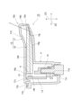
図5は、バイザー3の側面3cへのBSMユニット10の取付構造の例を示す断面図である。図5に示されるように、BSMユニット10は、後述する光源15を収容するハウジング11を備え、例えば、ハウジング11はスクリュー16を介してバイザー3の壁面3pに固定されてもよい。
Figure 5 is a cross-sectional view showing an example of a mounting structure of the
図6は、BSMユニット10を示す平面図である。図7は、図6のA-A線断面図である。図6及び図7に示されるように、BSMユニット10の露出部分10bの形状は、図6のA-A線断面に対して左右対称とされている。A-A線断面は、露出部分10bの中心10p及びバイザー3の縁部3dを含むと共にバイザー3の側面3cに直交する断面Sである。断面Sは、例えば、前述した第2方向D2及び側面3cに直交する第3方向D3の双方に延在する。
Figure 6 is a plan view showing the
第3方向D3に沿ってBSMユニット10を見たときに、BSMユニット10は、第1方向D1に延びる短辺、及び第2方向D2に延びる長辺を有すると共に、縁部3d側に突出する突出部10qを有する。突出部10qは、例えば、BSMユニット10の第1方向D1の中央を含む領域において縁部3dに向かって(図6では右側に)突出している。
When the
例えば、BSMユニット10の各部の形状は断面Sに対して左右対称とされている。このように、BSMユニット10の各部が断面Sに対して左右対称な形状とされていることにより、車両の右側に取り付けるBSMユニット10の構成と、車両の左側に取り付けるBSMユニット10の構成とを共通にすることができる。
For example, the shapes of the various parts of the
BSMユニット10は、光源15と、光源15を収容するハウジング11と、光源15からの光HをBSMユニット10の外部に出射するレンズ12とを備える。光源15は、例えば、LED光源である。BSMユニット10は、光Hを露出部分10bからBSMユニット10の外部に出射することによって、自車両の運転者に注意を促したり他の道路使用者に自車両の存在を把握させるインジケーターを表示する。レンズ12はハウジング11に取り付けられている。例えば、BSMユニット10は、更に、光源15が搭載されるプリント基板(PCB)である回路基板13と、回路基板13を介して光源15に電気的に接続されるコネクタ部14とを備える。
The
レンズ12の少なくとも一部(露出部分10b)はバイザー3の側面3cに露出している。レンズ12は、BSMユニット10の露出部分10bを有するアウターレンズ17と、アウターレンズ17の内側に位置するインナーレンズ18とを含んでいる。アウターレンズ17及びインナーレンズ18は、例えば、互いに別体とされている。
At least a portion (exposed
アウターレンズ17は、例えば、断面Sに対して左右対称とされている。一例として、アウターレンズ17は、ハウジング11に載せられるベース部17bと、ベース部17bにおいて突出する第1凸部17cと、第1凸部17cにおいて更に突出する第2凸部17dとを有する。
The
第3方向D3から見たときに、ベース部17bはハウジング11の内側に位置しており、第1凸部17cはベース部17bの内側に位置しており、第2凸部17dは第1凸部17cの内側に位置している。第3方向D3から見た場合におけるベース部17b及び第1凸部17cの少なくとも一部の形状は、例えば、角丸長方形状とされている。
When viewed from the third direction D3, the
ベース部17bはBSMユニット10の突出部10qを構成する第1突出部17fを有し、第1凸部17cは突出部10qを構成する第2突出部17gを有する。第1突出部17f及び第2突出部17gは、共に、縁部3d側に突出している。第2凸部17dは、例えば、第1凸部17cの第2突出部17gに設けられており、第3方向D3から見た第2凸部17dの形状は長方形状とされている。一例として、第2凸部17dの第2方向D2の端部側(縁部3d側)に前述した露出部分10bが設けられる。
The
アウターレンズ17は、その一部がバイザー3の側面3cに露出するレンズである。光源15から出射した光Hは、インナーレンズ18を介してアウターレンズ17に入射し、アウターレンズ17からBSMユニット10の外部に出射する。これにより、レンズ12が光ることとなってBSMユニット10が視認可能となる。BSMユニット10は、例えば、レンズ12を光らせることによって他車両の接近時等に点灯するインジケーターを表示し、これにより、自車両の運転者に注意を促すと共に、他の道路使用者に自車両の存在を把握させる。
The
アウターレンズ17の光Hの透過率は、例えば、インナーレンズ18の光Hの透過率よりも低い。一例として、アウターレンズ17の光Hの透過率は40%程度であり、インナーレンズ18の光Hの透過率は90%程度である。例えば、インナーレンズ18は無色透明とされており、アウターレンズ17は黒色の着色透明とされている。このように、アウターレンズ17の色彩が黒色の着色透明であることにより、アウターレンズ17の色彩をバイザー3の黒色に近づけることができるので、バイザー3の意匠性を高めることができる。
The transmittance of light H of the
ハウジング11は、アウターレンズ17が載せられる面11bとは反対側を向く面11cにコネクタ部14が挿入される挿入部11dを備える。挿入部11dは、例えば、面11cから窪む筒状とされており、挿入部11dの内部にコネクタ部14が挿入されることによって回路基板13にコネクタ部14が差し込まれる。このように、コネクタ部14が回路基板13に差し込まれることによってコネクタ部14及び回路基板13を介して光源15に電力が供給される。
The
図8は、ハウジング11を示す側面図である。図9は、BSMユニット10の分解斜視図である。図8及び図9に示されるように、ハウジング11は、断面Sに対して左右対称とされている。第2方向D2に沿って見たときにおけるハウジング11の形状は、例えば、長方形状とされており、ハウジング11はバイザー3に固定される一対の固定部11fを有する。
Figure 8 is a side view showing the
一対の固定部11fは、例えば、断面Sに対して左右対称とされている。固定部11fは、例えば、前述したスクリュー16が挿入される孔部11gを有する板状とされている。一例として、各固定部11fは第3方向D3に対してハウジング11の第2方向D2の中央側に傾斜している。例えば、各固定部11fの孔部11gにスクリュー16が挿入されてスクリュー16が壁面3pにねじ込まれることにより、バイザー3にBSMユニット10が強固に固定される。
The pair of fixing
ハウジング11は、光源15が搭載された回路基板13とインナーレンズ18とを収容する収容空間11hを有する。回路基板13は、例えば、第1方向D1及び第3方向D3の双方に延びる板状とされている。回路基板13は、矩形状とされた第1部分13bと、第1部分13bの収容空間11hの奥側に位置すると共に収容空間11hの奥側に向かうに従って幅が狭くなる第2部分13cとを有する。一例として、第2部分13cは台形状を呈する。
The
回路基板13のアウターレンズ17側を向く面13dには、光源15と、コネクタ部14を受け入れるレセプタクル部19とが搭載されている。例えば、コネクタ部14及びレセプタクル部19は、前述した断面Sに対して左右対称とされてもよい。コネクタ部14は、レセプタクル部19に差し込まれることによって回路基板13を介して光源15と電気的に接続される。
The
ハウジング11の内側を向く回路基板13の面13dにおいて、光源15及びレセプタクル部19は、例えば、上下に並ぶように配置されている。一例として、光源15は回路基板13の第1部分13bに搭載されており、レセプタクル部19は回路基板13の第2部分13cに搭載されている。光源15にはインナーレンズ18が対向するように配置される。インナーレンズ18は、例えば、光源15と第2方向D2に沿って対向している。
On the
図10は、インナーレンズ18を示す斜視図である。図11は、インナーレンズ18を第2方向D2に沿って見た側面図である。図7、図10及び図11に示されるように、インナーレンズ18は、例えば、回路基板13から離れるに従って徐々に薄くなる板状とされている。インナーレンズ18は、例えば、断面Sに対して左右対称とされている。
Figure 10 is a perspective view of the
インナーレンズ18は、光源15からの光Hが入射する入射部18bと、入射部18bから入射した光Hをアウターレンズ17に向けて反射する反射部18cと、反射部18cにおいて反射された光Hがインナーレンズ18の外部に出射する出射部18dとを有する。入射部18bは、光源15に第2方向D2に沿って対向しており、例えば、光源15に沿って延びると共にインナーレンズ18の内部に光Hを入射する入射面18fを有する。
The
例えば、反射部18cは、インナーレンズ18の内側面18g(ハウジング11の奥側、又はアウターレンズ17の反対側を向く面)における光源15との反対側に設けられる。一例として、反射部18cにおけるインナーレンズ18の厚さは、第2方向D2の端部側に向かうに従って薄くなっている。
For example, the reflecting
出射部18dは、インナーレンズ18の外側面18h(ハウジング11の外側、又はアウターレンズ17側を向く面)における光源15との反対側に設けられる。例えば、出射部18dは第1方向D1及び第2方向D2の双方に延びる平面に沿って延在しており、反射部18cはインナーレンズ18の第2方向D2の端部に向かうに従って出射部18dに近づくように斜めに延在している。
The
反射部18cには、レンズカット18jが形成されている。レンズカット18jは、第2方向D2に沿って並設された複数の凹凸18kを含んでいる。各凹凸18kは第1方向D1に沿って延びると共に第1方向D1の中央側に向かうに従って下方に湾曲するように延在している。凹凸18kの形状は、例えば、第2方向D2に沿って連続する三角波状とされている。
A
出射部18dには、例えば、レンズカット18jとは異なる形状のレンズカット18mが形成されている。レンズカット18mは、例えば、第1方向D1に沿って並ぶ複数の凸部18pを含んでいる。各凸部18pは第2方向D2に沿って延びている。例えば、各凸部18pの形状は、第1方向D1の中央に向かうに従って突出する湾曲面とされている。
In the
反射部18cのレンズカット18j、及び出射部18dのレンズカット18mは、光Hの配光パターンを構成し、所望の態様で光Hを拡散する機能を有する。反射部18cのレンズカット18jにおいて反射及び拡散された光Hは、出射部18dのレンズカット18mにおいて再度拡散されてアウターレンズ17の露出部分10bからBSMユニット10の外部に出射される。この光Hによって露出部分10bの略全体を光らせることができるので、BSMユニット10の露出部分10bを視認させることが可能となる。
Lens cut 18j of reflecting
次に、BSMユニット10から得られる作用効果について詳細に説明する。図2に例示されるように、BSMユニット10は、アウターミラー1のバイザー3の車体側を向く側面3cに設けられる。従って、BSMユニット10のインジケーターがアウターミラー1のミラー2ではなくバイザー3に表示されるので、ミラー2に映る景色等とは別の箇所にインジケーターを表示することができる。従って、インジケーターを視認しやすくすることができる。
Next, the effects and advantages obtained from the
BSMユニット10は、光源15を収容するハウジング11に取り付けられると共に光Hをハウジング11の外部に出射するレンズ12を備える。レンズ12の少なくとも一部(露出部分10b)は、バイザー3の側面3cから側面3cの面外方向に突出している。従って、外部に光Hを出射するレンズ12の少なくとも一部がバイザー3の側面3cの面外方向に突出しているので、他車両の運転者等がレンズ12からの光Hを視認することができる。
The
仮に、レンズからの光の出射面がバイザーの側面と面一である場合には、当該光の出射方向が自車両の運転者側に限定されうる。しかしながら、BSMユニット10では、レンズ12の少なくとも一部がバイザー3の側面3cから突出しているので、レンズ12からの光Hの出射方向が自車両の運転者側に限定されず自車両の後方等の広い範囲を含むこととなる。従って、後側方の他車両の運転者等にレンズ12からの光を視認させることができるので、自車両の存在を他車両の運転者等に把握させることができる。
If the light emission surface from the lens were flush with the side surface of the visor, the emission direction of the light would be limited to the driver's side of the vehicle. However, in the
また、バイザー3の側面3cに対するレンズ12の高さは、車両の後方側に向かうに従って高くなっていてもよい。この場合、レンズ12の高さが後方側に向かうに従って高くなっているので後側方の車両の運転者等によりレンズ12を視認させやすくすることができる。また、レンズ12の高さが後方側に向かうに従って高くなっている場合、バイザー3に対するBSMユニット10の組み付けを容易に行うことができる。
The height of the
また、レンズ12は、バイザー3の側面3cにおける車両の後方側に設けられていてもよい。この場合、レンズ12がバイザー3の側面3cにおける車両の後方側に設けられることにより、レンズ12は、アウターミラー1のミラー2に近い位置に設けられる。従って、ミラー2を視認する自車両の運転者の視線からレンズ12までの距離を短くすることができるので、自車両の運転者にレンズ12をより視認しやすくすることができる。また、レンズ12がバイザー3の側面3cの後方側に設けられることにより、後側方の他車両の運転者等が光るレンズ12をより視認しやすくなる。
The
図6及び図8に示されるように、BSMユニット10において、レンズ12の露出する部分(露出部分10b)の形状は、露出部分10bの中心10p及びバイザー3の縁部3dを含むと共にバイザー3の側面3cに直交する断面Sに対して左右対称とされている。すなわち、バイザー3の縁部3dから露出部分10bを見たときに、露出部分10bは左右対称とされている。
As shown in Figures 6 and 8, in the
従って、レンズ12の露出部分10bが左右対称な形状とされていることにより、車両の左側用のBSMユニット10と車両の右側用のBSMユニット10とを共通化することができる。その結果、設計及び製造等のコストを抑えることができると共に、組み付け等の誤りを抑制できるので部品の組み付けを容易に且つ高精度に行うことができる。
Therefore, because the exposed
また、ハウジング11は、バイザー3に固定される一対の固定部11fを有し、一対の固定部11fは、断面Sに対して左右対称とされていてもよい。この場合、ハウジング11が一対の固定部11fを備えており、一対の固定部11fが左右対称とされている。従って、車両の左側と車両の右側とでハウジング11の組み付けの構造及び組み付けの方法を共通化することができる。従って、設計及び製造等のコストの低減に寄与する。
The
図7及び図11に示されるように、レンズ12は、バイザー3の側面3cに露出するアウターレンズ17と、光源15からの光Hをアウターレンズ17に導くインナーレンズ18とを含んでおり、インナーレンズ18は、光源15からの光Hが通るレンズカット18j,18mを有し、レンズカット18j,18mは断面Sに対して左右対称とされていてもよい。
As shown in Figures 7 and 11, the
この場合、インナーレンズ18のレンズカット18j,18mを車両の左側用及び車両の右側用で共通化することができる。従って、光Hの出射パターンを組み付け時に容易に共通化することができる。また、インナーレンズ18を左側用及び右側用で共通化することができるので、インナーレンズ18のコストの低減に寄与する。
In this case, the
また、BSMユニット10は、光源15に電気的にされるコネクタ部14を備え、コネクタ部14の形状は、断面Sに対して左右対称とされていてもよい。この場合、コネクタ部14の形状を車両の左側用及び車両の右側用とで共通化することができる。従って、コネクタ部14の組み付けを容易に行うことができると共に、コネクタ部14のコストの低減に寄与する。
The
図5に示されるように、バイザー3は、アウターミラー1のミラー2の内側に位置する壁面3pを有し、ハウジング11は、壁面3pに固定されていてもよい。この場合、ミラー2の内側に位置する壁面3pにハウジング11が固定され、ハウジング11の固定部11fがバイザー3の側面3cに露出しないようにすることができるので、バイザー3の側面3cの凹凸を減らすことができる。従って、バイザー3の側面3cの構造をシンプルにすることができるので、バイザー3の成形時に用いる金型の構成を簡易にすることが可能となる。その結果、バイザー3の側面3cの意匠性及び製造性を高めることができる。
As shown in FIG. 5, the
図7及び図11に示されるように、レンズ12は、バイザー3の側面3cに露出するアウターレンズ17と、光源15からの光Hをアウターレンズ17に導くインナーレンズ18とを含んでおり、インナーレンズ18は、光源15からの光Hを反射する反射部18cと、反射部18cにおいて反射された光Hをアウターレンズ17に向けて出射する出射部18dとを有してもよい。
As shown in Figures 7 and 11, the
そして、反射部18cにレンズカット18jが形成されると共に、出射部18dにレンズカット18mが形成されていてもよい。この場合、インナーレンズ18の反射部18c及び出射部18dの双方にレンズカット18j,18mが形成されているので、インナーレンズ18による光Hの拡散効果を高めることができる。従って、より広い範囲にレンズ12からの光Hを拡散することができるので、BSMユニット10の視認性を高めることができる。なお、レンズカットの態様は、上記のレンズカット18j、18mの態様に限られず、例えば、反射部18c及び出射部18dのいずれか一方にレンズカットが形成されていてもよい。
Then, the
以上、本開示に係るBSMユニットの実施形態について説明した。しかしながら、本発明は、前述の実施形態に限定されるものではなく、各請求項に記載した要旨を変更しない範囲において変形し、又は他のものに適用されたものであってもよい。すなわち、本開示に係るBSMユニットの各部の形状、大きさ、数、材料及び配置態様は、上記の要旨の範囲内において適宜変更可能である。 The above describes an embodiment of the BSM unit according to the present disclosure. However, the present invention is not limited to the above-described embodiment, and may be modified or applied to other things without changing the gist of the claims. In other words, the shape, size, number, material, and arrangement of each part of the BSM unit according to the present disclosure may be modified as appropriate within the scope of the above gist.
例えば、前述の実施形態では、少なくとも一部がバイザー3の側面3cから側面3cの面外方向に突出しているBSMユニット10について説明した。しかしながら、BSMユニットはバイザー3の側面3cから突出しないものであってもよい。また、前述の実施形態では、BSMユニット10は縁部3dの隣接位置に設けられており、BSMユニット10と縁部3dとの間に第1方向D1に沿って延びる線状部3hが形成されている例について説明した。しかしながら、BSMユニットの配置場所については上記の例に限られず適宜変更可能である。
For example, in the above embodiment, a
図12は、変形例に係るBSMユニット20を示している。BSMユニット20は、例えば、光Hを出射するレンズ22を備えており、レンズ22の少なくとも一部がバイザー3の側面3cに露出している。そして、レンズ22の少なくとも一部は、バイザー3の縁部3dに達している。
Figure 12 shows a modified
BSMユニット20は、前述したBSMユニット10と同様、バイザー3の車体側を向く側面3cに設けられるので、ミラー2に映る景色等とは別の箇所にインジケーターを表示することができる。従って、インジケーターを視認しやすくすることができる。そして、レンズ22の少なくとも一部は、バイザー3の側面3cに露出すると共にバイザー3の縁部3dに達している。
The
従って、外部に光Hを出射するレンズ22がバイザー3の側面3cに露出すると共にバイザー3の縁部3dに達していることにより、レンズ22からの光の出射方向は、自車両の運転者等に限定されず、自車両の後方等の広い範囲を含むこととなる。従って、後側方の車両の運転者等にレンズ22からの光Hを視認させることができるので、自車両の存在を他車両の運転者等に把握させることができる。以上より、BSMユニット20からは前述したBSMユニット10と同様の作用効果が得られる。
Therefore, because the
また、前述の実施形態では、レンズ12が互いに別体とされているアウターレンズ17及びインナーレンズ18を備える例について説明した。しかしながら、BSMユニットのレンズは一体のレンズであってもよい。更に、前述の実施形態では、各部の形状は断面Sに対して左右対称とされているBSMユニット10について説明した。しかしながら、BSMユニットの一部が断面Sに対して左右対称とされていなくてもよい。例えば、ハウジング11、レンズ12、回路基板13及びコネクタ部14の少なくともいずれかが断面Sに対して左右対称とされていなくてもよい。
In the above embodiment, an example was described in which the
以上のようにBSMユニットの各部の形状は、前述の要旨の範囲内において適宜変更可能である。更に、BSMユニットが取り付けられるアウターミラーの形状、大きさ、種類及び配置態様についても適宜変更可能である。 As described above, the shape of each part of the BSM unit can be modified as appropriate within the scope of the aforementioned gist. Furthermore, the shape, size, type, and arrangement of the outer mirror to which the BSM unit is attached can also be modified as appropriate.
1…アウターミラー、2…ミラー、2b…鏡面、3…バイザー、3b…上面、3c…側面、3d…縁部、3f,3g…開口、3h…線状部、3p…壁面、3q…第1壁面、3r…第2壁面、3s…第3壁面、3t…筒状部、10,20…BSMユニット、10b…露出部分、10c…長辺、10d…短辺、10f…平滑面、10g…凸部、10h…傾斜面、10j…頂部、10k…第1側面、10m…第2側面、10p…中心、10q…突出部、11…ハウジング、11b,11c…面、11d…挿入部、11f…固定部、11g…孔部、11h…収容空間、12,22…レンズ、13…回路基板、13b…第1部分、13c…第2部分、13d…面、14…コネクタ部、15…光源、16…スクリュー、17…アウターレンズ、17b…ベース部、17c…第1凸部、17d…第2凸部、17f…第1突出部、17g…第2突出部、18…インナーレンズ、18b…入射部、18c…反射部、18d…出射部、18f…入射面、18g…内側面、18h…外側面、18j,18m…レンズカット、18k…凹凸、18p…凸部、19…レセプタクル部、D1…第1方向、D2…第2方向、D3…第3方向、H…光、L1,L2…基準線、S…断面。 1...outer mirror, 2...mirror, 2b...mirror surface, 3...visor, 3b...upper surface, 3c...side surface, 3d...edge portion, 3f, 3g...opening, 3h...linear portion, 3p...wall surface, 3q...first wall surface, 3r...second wall surface, 3s...third wall surface, 3t...tubular portion, 10, 20...BSM unit, 10b...exposed portion, 10c...long side, 10d...short side, 10f...smooth surface, 10g...convex portion, 10h...inclined surface, 10j...top, 10k...first side surface, 10m...second side surface, 10p...center, 10q...protruding portion, 11...housing, 11b, 11c...surface, 11d...insertion portion, 11f...fixing portion, 11g...hole portion, 11h...storage space, 12, 22...le Lens, 13...circuit board, 13b...first part, 13c...second part, 13d...surface, 14...connector part, 15...light source, 16...screw, 17...outer lens, 17b...base part, 17c...first convex part, 17d...second convex part, 17f...first protrusion, 17g...second protrusion, 18...inner lens, 18b...entrance part, 18c...reflection part, 18d...exit part, 18f...entrance surface, 18g...inner surface, 18h...outer surface, 18j, 18m...lens cut, 18k...unevenness, 18p...protrusion, 19...receptacle part, D1...first direction, D2...second direction, D3...third direction, H...light, L1, L2...reference line, S...cross section.
Claims (5)
光源と、
前記光源を収容するハウジングと、
前記ハウジングに取り付けられ、前記光源からの光を前記ハウジングの外部に出射するレンズと、
を備え、
前記BSMユニットは、前記側面に取り付けられた状態におけるものであり、
前記バイザーは、前記側面の前記車両の後方側に位置すると共に前記アウターミラーのミラーを囲む縁部を有し、
前記レンズの少なくとも一部は、前記バイザーの前記側面に露出しており、
前記レンズの前記露出する部分の形状は、前記露出する部分の中心を通ると共に、前記縁部と直交し、かつ前記バイザーの前記側面に直交する断面に対して対称とされており、
前記ハウジングは、前記バイザーに固定される一対の固定部を有し、
前記一対の固定部は、前記断面に対して対称とされている、
BSMユニット。 A BSM unit that is attached to a side surface of a visor of an outer mirror provided on a vehicle body, the side surface facing the vehicle body,
A light source;
a housing for accommodating the light source;
a lens attached to the housing and configured to direct light from the light source to an outside of the housing;
Equipped with
the BSM unit is attached to the side surface,
the visor is located on the side surface toward the rear of the vehicle and has an edge portion surrounding the mirror of the outer mirror,
At least a portion of the lens is exposed on the side surface of the visor;
The shape of the exposed portion of the lens is symmetrical with respect to a cross section that passes through a center of the exposed portion, is perpendicular to the edge, and is perpendicular to the side surface of the visor;
The housing has a pair of fixing portions fixed to the visor,
The pair of fixing portions are symmetrical with respect to the cross section.
BSM unit.
前記インナーレンズは、前記光源からの光が通るレンズカットを有し、
前記レンズカットは、前記断面に対して対称とされている、
請求項1に記載のBSMユニット。 The lens includes an outer lens exposed to the side surface of the visor and an inner lens that guides light from the light source to the outer lens,
The inner lens has a lens cut through which light from the light source passes,
The lens cut is symmetrical with respect to the cross section.
The BSM unit of claim 1 .
前記コネクタ部の形状は、前記断面に対して対称とされている、
請求項1または請求項2に記載のBSMユニット。 a connector portion electrically connected to the light source,
The shape of the connector portion is symmetrical with respect to the cross section.
A BSM unit according to claim 1 or 2.
前記ハウジングは、前記壁面に固定されている、
請求項1~3のいずれか一項に記載のBSMユニット。 The visor has a wall surface located inside the mirror of the outer mirror,
The housing is fixed to the wall.
A BSM unit according to any one of claims 1 to 3.
前記インナーレンズは、前記光源からの光を反射する反射部と、前記反射部において反射された光を前記アウターレンズに向けて出射する出射部とを有し、
前記反射部及び前記出射部の少なくともいずれかにレンズカットが形成されている、
請求項1~4のいずれか一項に記載のBSMユニット。 The lens includes an outer lens exposed on a side surface of the visor and an inner lens that guides light from the light source to the outer lens,
The inner lens has a reflecting portion that reflects light from the light source and an emitting portion that emits the light reflected at the reflecting portion toward the outer lens,
A lens cut is formed in at least one of the reflecting portion and the emitting portion.
A BSM unit according to any one of claims 1 to 4.
Priority Applications (2)
| Application Number | Priority Date | Filing Date | Title |
|---|---|---|---|
| JP2019228594A JP7666892B2 (en) | 2019-12-18 | 2019-12-18 | BSM unit |
| US17/121,993 US11377035B2 (en) | 2019-12-18 | 2020-12-15 | BSM unit |
Applications Claiming Priority (1)
| Application Number | Priority Date | Filing Date | Title |
|---|---|---|---|
| JP2019228594A JP7666892B2 (en) | 2019-12-18 | 2019-12-18 | BSM unit |
Publications (2)
| Publication Number | Publication Date |
|---|---|
| JP2021095044A JP2021095044A (en) | 2021-06-24 |
| JP7666892B2 true JP7666892B2 (en) | 2025-04-22 |
Family
ID=76430297
Family Applications (1)
| Application Number | Title | Priority Date | Filing Date |
|---|---|---|---|
| JP2019228594A Active JP7666892B2 (en) | 2019-12-18 | 2019-12-18 | BSM unit |
Country Status (2)
| Country | Link |
|---|---|
| US (1) | US11377035B2 (en) |
| JP (1) | JP7666892B2 (en) |
Families Citing this family (1)
| Publication number | Priority date | Publication date | Assignee | Title |
|---|---|---|---|---|
| KR20230036228A (en) * | 2021-09-07 | 2023-03-14 | 현대자동차주식회사 | Black Image type Hidden Lighting Lamp and Vehicles Thereof |
Citations (8)
| Publication number | Priority date | Publication date | Assignee | Title |
|---|---|---|---|---|
| US20080316054A1 (en) | 2005-07-06 | 2008-12-25 | Donnelly Corporation | Vehicle Exterior Mirror Assembly With Blind Spot Indicator |
| US20100026475A1 (en) | 2008-08-04 | 2010-02-04 | Visiocorp Patents S.à.r.l. | Exterior rear view mirror with indicator light |
| JP2011054523A (en) | 2009-09-04 | 2011-03-17 | Koito Mfg Co Ltd | Side turn signal lamp |
| JP2013226877A (en) | 2012-04-24 | 2013-11-07 | Mitsuba Corp | Vehicle illumination body and door mirror with illumination body |
| JP3189170U (en) | 2013-12-13 | 2014-02-27 | 宸偉 許 | Side mirror light guide structure |
| JP2014151651A (en) | 2013-02-04 | 2014-08-25 | Koito Mfg Co Ltd | Vehicular door mirror lamp |
| JP2014184930A (en) | 2013-03-25 | 2014-10-02 | Tokai Rika Co Ltd | Obstacle reporting system |
| JP2016172545A (en) | 2015-03-17 | 2016-09-29 | マグナ・ミラーズ・(タイツァン)・オートモーティヴ・テクノロジー・カンパニー・リミテッドMagna Mirrors (Taicang) Automotive Technology Co., Ltd. | Vehicle lane change warning lamp fitting |
Family Cites Families (11)
| Publication number | Priority date | Publication date | Assignee | Title |
|---|---|---|---|---|
| US5497306A (en) * | 1993-02-01 | 1996-03-05 | Donnelly Corporation | Exterior vehicle security light |
| US6511192B1 (en) * | 1999-12-17 | 2003-01-28 | Britax Vision Systems (North America) Inc. | Side view mirror with integral lighting |
| US7008089B1 (en) * | 2000-02-01 | 2006-03-07 | Schefenacker Vision Systems Usa Inc. | Exterior rear view mirror having a chin strap and a repeater |
| US6325517B1 (en) * | 2000-02-11 | 2001-12-04 | Su Chang Kuo | Rear vision mirror with cold light direction signal indicator |
| US6986596B2 (en) * | 2003-09-02 | 2006-01-17 | Trw Automotive U.S. Llc | Exterior rearview mirror assembly |
| DE102004048669B4 (en) * | 2003-10-07 | 2007-06-14 | Toyoda Gosei Co., Ltd. | Vehicle side mirror device |
| DE102004025385A1 (en) * | 2004-05-17 | 2005-12-08 | Schefenacker Vision Systems Germany Gmbh & Co. Kg | Exterior rearview mirror for vehicles, in particular motor vehicles |
| US7527403B2 (en) * | 2005-06-14 | 2009-05-05 | Donnelly Corp. | Mirror assembly for vehicle |
| DE102009019092A1 (en) * | 2009-04-20 | 2010-11-04 | SMR Patents S.à.r.l. | Minimal LED turn signal in the exterior mirror |
| DE102015108486A1 (en) * | 2015-05-29 | 2016-12-01 | Hella Kgaa Hueck & Co. | Side indicator for vehicles |
| EP3463980B1 (en) * | 2016-06-01 | 2023-05-03 | SMR Patents S.à.r.l. | A lamp assembly for a vehicle |
-
2019
- 2019-12-18 JP JP2019228594A patent/JP7666892B2/en active Active
-
2020
- 2020-12-15 US US17/121,993 patent/US11377035B2/en active Active
Patent Citations (8)
| Publication number | Priority date | Publication date | Assignee | Title |
|---|---|---|---|---|
| US20080316054A1 (en) | 2005-07-06 | 2008-12-25 | Donnelly Corporation | Vehicle Exterior Mirror Assembly With Blind Spot Indicator |
| US20100026475A1 (en) | 2008-08-04 | 2010-02-04 | Visiocorp Patents S.à.r.l. | Exterior rear view mirror with indicator light |
| JP2011054523A (en) | 2009-09-04 | 2011-03-17 | Koito Mfg Co Ltd | Side turn signal lamp |
| JP2013226877A (en) | 2012-04-24 | 2013-11-07 | Mitsuba Corp | Vehicle illumination body and door mirror with illumination body |
| JP2014151651A (en) | 2013-02-04 | 2014-08-25 | Koito Mfg Co Ltd | Vehicular door mirror lamp |
| JP2014184930A (en) | 2013-03-25 | 2014-10-02 | Tokai Rika Co Ltd | Obstacle reporting system |
| JP3189170U (en) | 2013-12-13 | 2014-02-27 | 宸偉 許 | Side mirror light guide structure |
| JP2016172545A (en) | 2015-03-17 | 2016-09-29 | マグナ・ミラーズ・(タイツァン)・オートモーティヴ・テクノロジー・カンパニー・リミテッドMagna Mirrors (Taicang) Automotive Technology Co., Ltd. | Vehicle lane change warning lamp fitting |
Also Published As
| Publication number | Publication date |
|---|---|
| US11377035B2 (en) | 2022-07-05 |
| US20210188176A1 (en) | 2021-06-24 |
| JP2021095044A (en) | 2021-06-24 |
Similar Documents
| Publication | Publication Date | Title |
|---|---|---|
| JP4930787B2 (en) | VEHICLE LIGHT AND LIGHT GUIDE LENS USED FOR VEHICLE LIGHT | |
| EP2353937A1 (en) | Vehicle lamp | |
| US20200158309A1 (en) | Lamp and vehicle having same | |
| EP2489550A2 (en) | Vehicle lamp | |
| US7220030B2 (en) | Exterior mirror having lamp and exterior rear-view mirror having lamp | |
| EP2327585A1 (en) | Vehicular lamp | |
| KR101804311B1 (en) | Back light unit | |
| EP2159477B1 (en) | Vehicle lamp using a light guide | |
| JP7309341B2 (en) | vehicle lamp | |
| JP2019200928A (en) | Vehicular lighting fixture | |
| JP2020113433A (en) | Rear combination lamp | |
| JP7666892B2 (en) | BSM unit | |
| JP6887257B2 (en) | Vehicle lighting | |
| US20250277569A1 (en) | Vehicle lamp | |
| JP2019200937A (en) | Vehicle lamp fitting | |
| JP7473332B2 (en) | BSM unit | |
| US11590879B2 (en) | Vehicle lamp body device | |
| JP7629800B2 (en) | Vehicle lighting fixtures | |
| JP4666174B2 (en) | Vehicle lighting | |
| US12474028B2 (en) | Light assembly for a motor vehicle including a shaped film | |
| JP7357426B2 (en) | Vehicle lights | |
| JP2021002450A (en) | Vehicle lamp fitting unit | |
| JP2020068111A (en) | Vehicle lighting | |
| JP2011233250A (en) | Lighting fixture for vehicle | |
| JP2019204615A (en) | Vehicular lighting fixture |
Legal Events
| Date | Code | Title | Description |
|---|---|---|---|
| A621 | Written request for application examination |
Free format text: JAPANESE INTERMEDIATE CODE: A621 Effective date: 20220928 |
|
| A977 | Report on retrieval |
Free format text: JAPANESE INTERMEDIATE CODE: A971007 Effective date: 20230619 |
|
| A131 | Notification of reasons for refusal |
Free format text: JAPANESE INTERMEDIATE CODE: A131 Effective date: 20230718 |
|
| A521 | Request for written amendment filed |
Free format text: JAPANESE INTERMEDIATE CODE: A523 Effective date: 20230915 |
|
| A02 | Decision of refusal |
Free format text: JAPANESE INTERMEDIATE CODE: A02 Effective date: 20231205 |
|
| A521 | Request for written amendment filed |
Free format text: JAPANESE INTERMEDIATE CODE: A523 Effective date: 20241218 |
|
| A61 | First payment of annual fees (during grant procedure) |
Free format text: JAPANESE INTERMEDIATE CODE: A61 Effective date: 20250410 |
|
| R150 | Certificate of patent or registration of utility model |
Ref document number: 7666892 Country of ref document: JP Free format text: JAPANESE INTERMEDIATE CODE: R150 |